rth
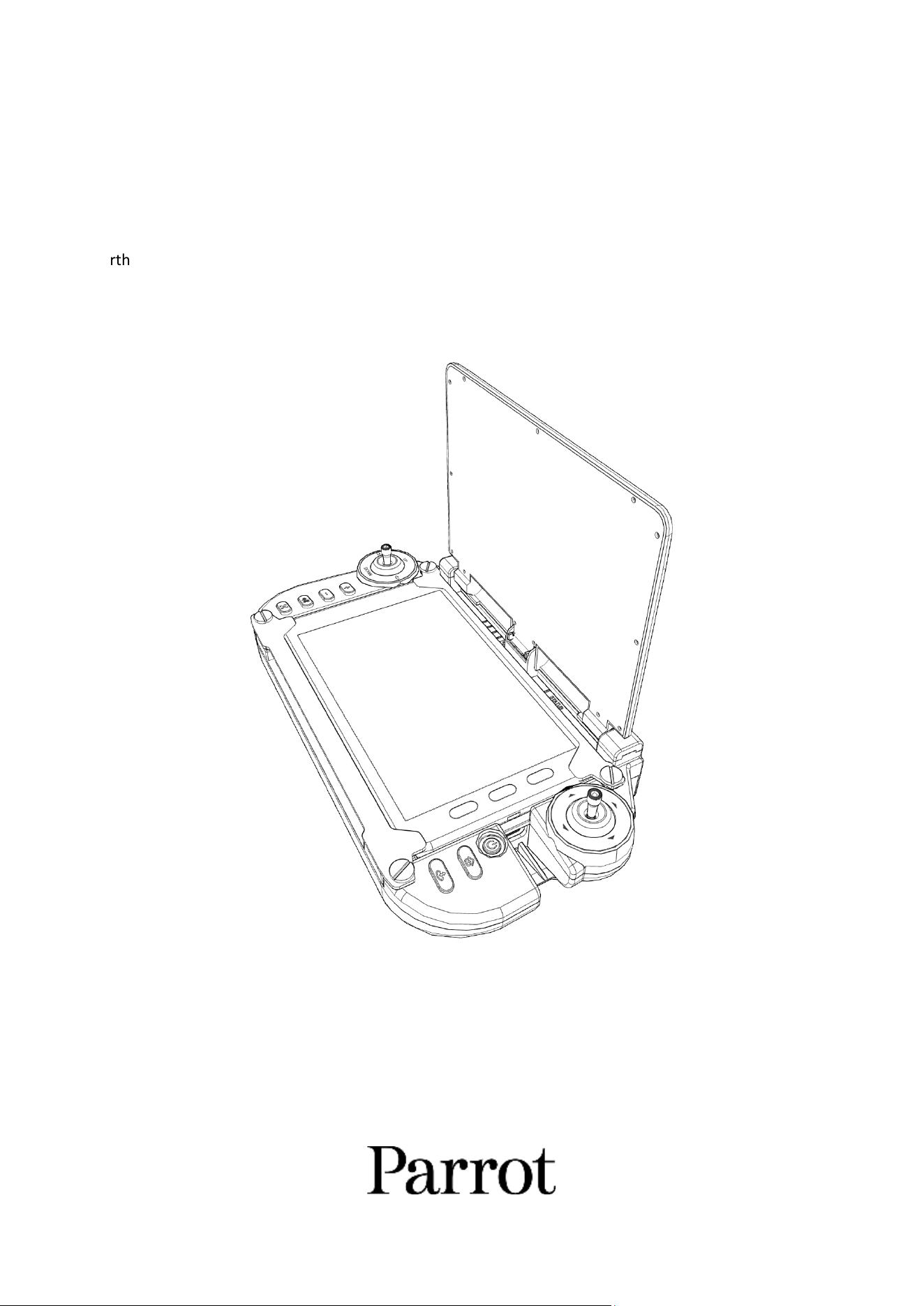
SKYCONTROLLER UKR
& FreeFlight 8
User Guide
Version: 8.4.0.0
Updated: May 15
th
, 2026
2
1. Documentaon changelog
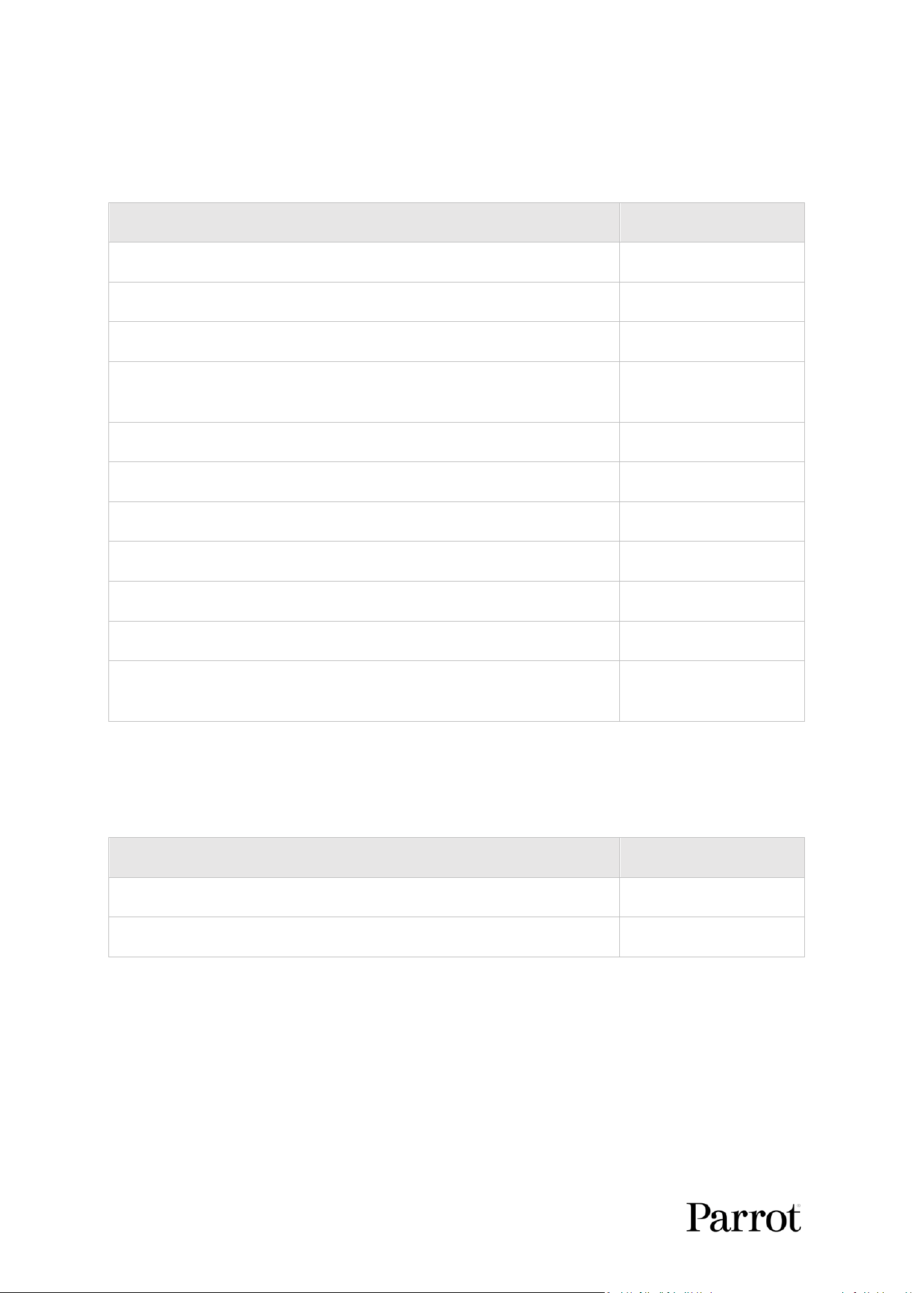
This secon details the major changes to Parrot’s technical documentaon since version 8.3.4.0
released on January 29
th
, 2026.
What changed
Where
Technical specicaons chapter updated.
Page 7
Landmarks subchapter added.
Page 31
Flight parameters subchapter updated.
Page 66
RTH and Safety subchapter separated into 2 individual chapters; RTH, and
Safety.
Pages 67, and 71
Flight area subchapter removed, and text moved to Safety subchapter.
Page 71
Maps subchapter updated with informaon about oine map limits.
Page 89
Stream sharing subchapter updated.
Page 90
Drone subchapter updated.
Page 98
Upload logs subchapter added.
Page 124
Developer subchapter updated.
Page 126
Appendix 2: EU Data Act informaon and system data overview chapter
updated.
Page 136
1.1. Ecosystem versions
This secon details the soware versions for the full ecosystem available at the me of wring this
user guide:
Ecosystem element
Soware version
Applicaon
8.4.0
Controller
8.4.0

S K Y C O N T R O L L E R UKR
3
© 2026 Parrot Drones SAS. All Rights Reserved.
2. Using this guide
Parrot recommends that you read the following user guide thoroughly before your rst ight. This
user guide completes the ANAFI UKR documentaon, which also includes the:
- Skycontroller UKR and FreeFlight 8 release notes – available upon request.
Read the Flight Safety Guide to have complementary informaon about safety, operaonal limitaons
for use and maintenance of the ecosystem. Always verify that you are using the latest version of the
user guide.
This guide is specic to a single controller conguraon, consisng of:
- The Parrot Skycontroller UKR ground control staon.
- The Parrot FreeFlight 8 ight applicaon.
Read fully at least one me . It answers most quesons that most users may encounter when they
use Skycontroller UKR and FreeFlight 8.
Keep it for reference and stay alert for updates. Updates are mandatory and must be systemacally
performed prior to any ight to ensure maximum performance and safety.
The Table of contents, starng on page 4, is acve. Click a tle to access the corresponding secon.
This user guide has no index. the keyboard shortcut Ctrl + F (Windows) or Command + F (Mac) to
browse all occurrences of any keyword (ight, sengs, obstacle avoidance, gimbal, photo, ISO, etc)
4
3. Table of contents
1. Documentaon changelog ...................... 2
1.1. Ecosystem versions ........................ 2
2. Using this guide ....................................... 3
3. Table of contents ..................................... 4
4. Foreword ................................................. 6
4.1. Skycontroller UKR ecosystem and
variants ....................................................... 6
4.2. Skycontroller UKR smart baery .... 6
4.3. HDMI .............................................. 6
4.4. Technical support ........................... 6
5. Technical specicaons ........................... 7
6. Pre-ight checklist ................................... 8
6.1. Transport & handling ..................... 8
6.2. Equipment ...................................... 8
7. Geng started ......................................... 9
8. Skycontroller UKR .................................. 11
8.1. Connecvity ................................. 13
8.2. HDMI video output ...................... 13
8.3. LED status indicator color codes .. 13
8.4. Pairing the aircra to a
Skycontroller UKR ...................................... 13
8.5. Remote antenna feature with a
second Skycontroller UKR .......................... 14
9. Skycontroller UKR Mission ..................... 16
9.1. Connecvity ................................. 18
9.2. HDMI video output ...................... 18
9.3. LED status indicator color codes .. 18
9.4. MARS Ranger................................ 18
9.5. Pairing the aircra to a
Skycontroller UKR Mission ......................... 20
9.6. Cloud antenna .............................. 21
10. Pilong basics ........................................ 23
10.1. Ground Take-o ........................... 23
10.2. Hand launch ................................. 23
10.3. Flying ........................................... 24
10.4. Gimbal controls ........................... 24
10.5. Landing ........................................ 25
10.6. Hand Landing ............................... 25
10.7. Return to Home ........................... 26
11. FreeFlight 8 ........................................... 28
11.1. Cursor on Target .......................... 30
11.2. Landmarks ................................... 31
11.3. Image mode ................................. 32
11.4. Exposure adjustments ................. 34
11.5. White balance .............................. 36
11.6. Thermal camera ........................... 37
12. Flight modes .......................................... 41
12.1. Pilong ......................................... 41
12.2. Tracking ........................................ 41
12.3. Touch & Fly .................................. 44
12.4. Flight plan .................................... 47
13. Sengs .................................................. 60
13.1. Quick sengs .............................. 60
13.2. Gallery ......................................... 62
13.3. Flight logs ..................................... 63
13.4. Flight parameters......................... 66
13.5. RTH .............................................. 67
13.6. Safety ........................................... 71
13.7. GPS .............................................. 74
13.8. Connecon .................................. 78
13.9. Recording ..................................... 84
13.10. Interface ...................................... 85
13.11. Maps ............................................ 86
13.12. Stream sharing ............................. 90
13.13. Soware ...................................... 95
13.14. Drone ........................................... 98
13.15. Controller ................................... 110

S K Y C O N T R O L L E R UKR
5
© 2026 Parrot Drones SAS. All Rights Reserved.
13.16. Storage ....................................... 117
13.17. Account ...................................... 119
13.18. Upload logs ................................ 124
13.19. Cercates ................................. 126
13.20. Developer ................................... 126
14. Maintenance and troubleshoong ...... 127
14.1. Skycontroller UKR hard reset ..... 127
14.2. FreeFlight 8 device hard reset .... 127
14.3. Webserver .................................. 127
14.4. Aircra end of service life .......... 129
15. Accessories .......................................... 130
15.1. Open-source 3D printable
accessories............................................... 130
15.2. Proprietary accessories .............. 130
15.3. 3rd party accessories ................. 133
16. Appendix 1: Operaonal Checklist ...... 134
16.1. Soware update & calibraon .. 134
16.2. Skycontroller UKR & Aircra o 134
16.3. Skycontroller UKR & Aircra on 134
16.4. Before Take-o .......................... 135
16.5. Aer Take-o ............................. 135
16.6. Before landing ........................... 135
16.7. Aer landing .............................. 135
17. Appendix 2: EU Data Act informaon and
System data overview ................................. 136
17.1. Product data .............................. 136
17.2. Related service data .................. 136
17.3. How to access data .................... 136
17.4. How to contact us ...................... 137
18. Appendix 3: Disclaimer ....................... 138
6
4. Foreword
4.1. Skycontroller UKR ecosystem and variants
In the following pages, the word ecosystem refers to the controller (Skycontroller UKR) and the
FreeFlight 8 ying app. The word device refers to the tablet on which FreeFlight 8 is installed.
This user guide documents the Skycontroller UKR, Skycontroller UKR Mission, and MARS Ranger
which can be used with 4 Parrot aircra ecosystem variants:
• ANAFI UKR
• ANAFI UKR GOV
• ANAFI UKR XLR
• ANAFI UKR Mission
Screenshots throughout this guide may dier from the user’s FreeFlight 8 applicaon interface due to
individual variant conguraons.
4.2. Skycontroller UKR smart baery
The Skycontroller UKR baery enters a Wintering mode when not in use for 10 consecuve days.
Users must connect a charger to the Skycontroller UKR USB-C charging port to wake the baery up
and charge it completely before you y for the rst me.
4.3. HDMI
The Skycontroller UKR has an HDMI port, which enables you to stream images to a screen or to HDMI
goggles. Parrot recommends using a cered HDMI to HDMI cable (not included in the box) to
connect external pieces of equipment to the Skycontroller UKR.
4.4. Technical support
Parrot recommends that you use your Parrot.CLOUD account to allow Parrot to store your ight data.
Sharing your data, even anonymously, enables us to improve our products. It also directly benets all
idenable users in case they need to contact Parrot support teams.
CAUTION: If you do not share flight data / logs for the purposes of receiving support, you limit your
ability to receive technical support, warranty, or both from Parrot.
S K Y C O N T R O L L E R UKR
7
© 2026 Parrot Drones SAS. All Rights Reserved.
5. Technical specicaons
GROUND CONTROL STATION
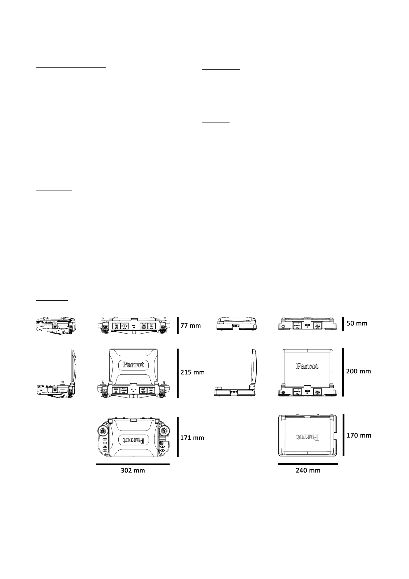
• Size folded: 171 x 302 x 77 mm (6.7 x 11.9 x 3.0")
• Size unfolded: 171 x 302 x 215 mm (6.7 x 11.9 x 8.5")
• Mass:
o Skycontroller UKR: 1,765 g (3.89 lb)
o Skycontroller UKR Mission: 1,450 g (3.2 lb)
o Skycontroller UKR GOV: 1,765 g (3.89 lb)
o Skycontroller UKR XLR: 1,765 g (3.89 lb)
• Battery capacity: 10,000 mAh
• Battery voltage (nominal): 7.2 V
• Battery charging duration: 2 h (2 h 30 min with tablet)
• Battery life: 4 h 30 min[1]
• Connectivity:
o USB-C port
o USB-A port
o HDMI port
o Ethernet port
• IP53: Rain and dust resistant
• Operating temperature: -36 °C to 50 °C (-33 °F to 122 °F)
MARS RANGER
• Size folded: 170 x 240 x 50 mm (6.7 x 9.4 x 2.0 ")
• Size unfolded: 170 x 240 x 200 mm (6.7 x 9.4 x 7.9 ")
• Mass: 1,200 g (2.65 lb)
• Battery capacity: 10,000 mAh
• Battery voltage (nominal): 7.2 V
• Battery charging duration: 2 h
• Battery life: 4 h 30 min[1]
• Connectivity:
o USB-C port
o Ethernet port
• IP53: Rain and dust resistant
• Operating temperature: -36 °C to 50 °C (-33 °F to 122 °F)
CYBERSECURITY
• Zero data shared without user consent
• TAA & NDAA compliant
• Blue UAS program approved
• Manage your data privately between drone and device OR share
anonymous data on secured European servers
• Digitally signed firmware
• Compliant with FIPS140-2
RADIO LINK
• MARS (ANAFI UKR & ANAFI UKR XLR only):
o Over 1.5 GHz bandwidth:
▪ spread across 8 bands 1.8 – 5 GHz (ANAFI UKR)
▪ spread across 10 bands 1.8 – 5.85 GHz (ANAFI UKR XLR)
o TX & RX differentiated frequencies
o Radio-jamming resistance through Frequency hopping
o Direct video stream resolution: 1080p 30 fps
o AES 256 encryption: packet and radio level
• Wi-Fi (ANAFI UKR GOV only):
o Wi-Fi 802.11ax
o Direct video stream resolution: 1080p 30 fps
o AES 256 encryption: Packet and radio level
o Operating frequencies: 2.4 GHz, 5GHz UNII-1, & UNII-3
• LoRa:
o Activates when main link is lost
o AES 128 and ChaCha20 encryption
o Frequency bands: EU - 863 to 870 MHz, US - 902 to 928 MHz
• Cellular (ANAFI UKR GOV & ANAFI UKR XLR only):
o Cellular connectivity: 5G NR with 4G LTE fallback
o AES 256 encryption: Packet level
o Seamless switching
[2]
:
▪ 5G / Wi-Fi
▪ 5G /MARS
o Flies Beyond Visual Line of Sight
•
[1] Extreme temperatures, or suboptimal conditions may affect battery autonomy.
[2] Radio link switching depends on individual configurations.
DIMENSIONS
Ground control station
MARS Ranger
Figure 1: Skycontroller UKR dimensions
Images not to scale
8
6. Pre-ight checklist
6.1. Transport & handling
- Always transport the Skycontroller UKR safely in the relevant locaon in the hard case.
- Protect the baery from extreme temperature, both low and high. Try to keep the baery as
close as possible to 25 °C (77 °F).
- Always keep the hard case with the Skycontroller UKR and device in dry places.
6.2. Equipment
- Ensure that you download the latest version of FreeFlight 8, and that your Skycontroller UKR
is up to date with the latest version of rmware.
IMPORTANT: Updates are mandatory and must be performed systemacally prior to any ight to
ensure maximum performance and safety.
- Ensure that the Skycontroller UKR baery is fully charged.
S K Y C O N T R O L L E R UKR
9
© 2026 Parrot Drones SAS. All Rights Reserved.
7. Geng started
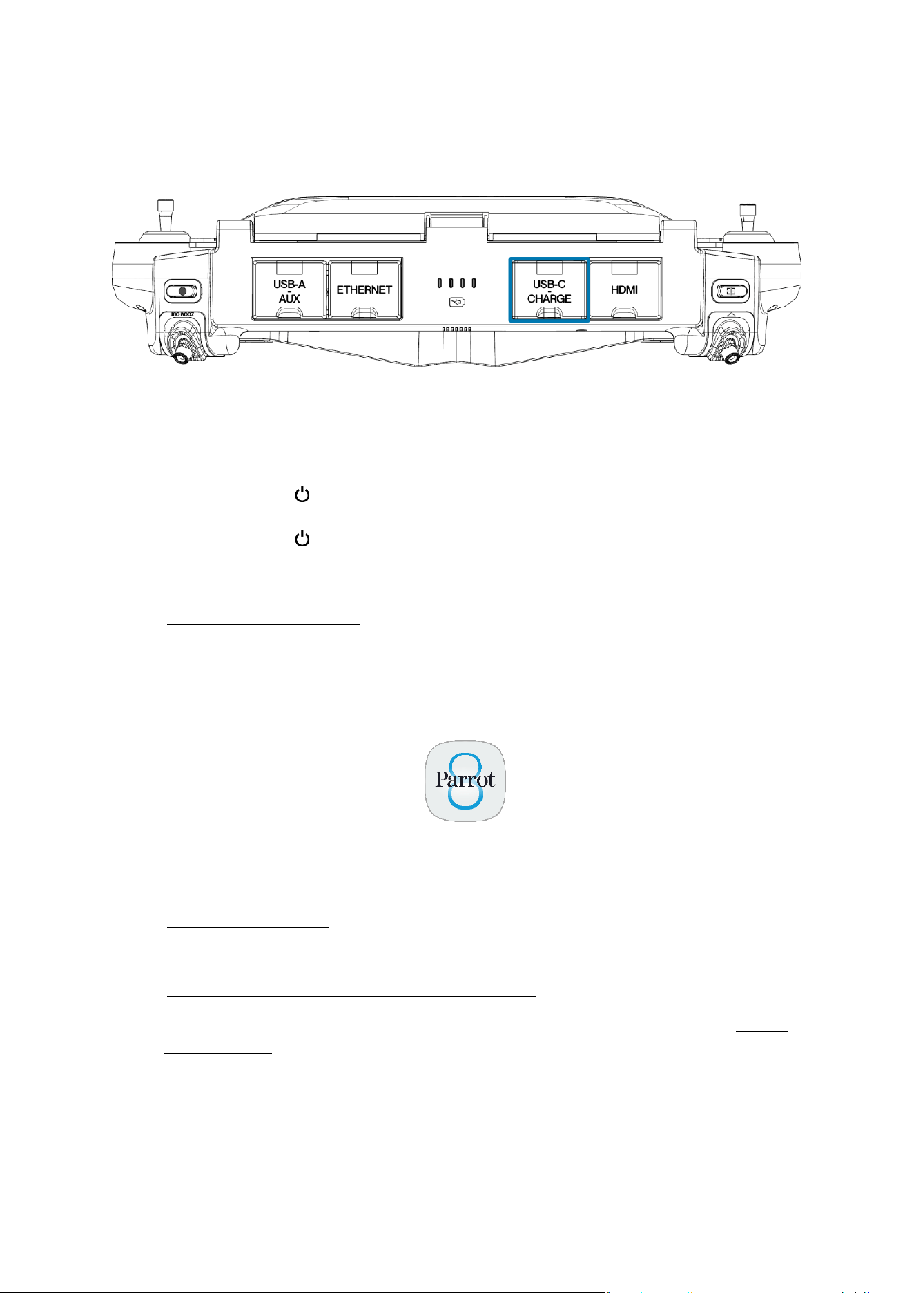
1. Open the Skycontroller UKR’s USB-C CHARGE cover to expose the USB-C charging port.
Figure 2: Skycontroller UKR rear view with interface ports closed
2. Connect Skycontroller UKR to the enclosed USB-PD charger with one of the enclosed USB-C
to USB-C cables.
3. Wait unl the enre ecosystem is fully charged.
4. Press and hold the Power buon on the integrated tablet in Skycontroller UKR for 3
seconds.
5. Press and hold the Power buon on Skycontroller UKR for 2 seconds.
The Skycontroller UKR’s status LED ashes white to indicate that the controller is boong.
Refer to chapter 8. Skycontroller UKR for more informaon.
The fully secure pilong soware of Skycontroller UKR, FreeFlight 8, guarantees the integrity of data
exchanges for the full ecosystem, and manages updates (pilong soware, drone, remote control).
FreeFlight 8 is preinstalled on Skycontroller UKR’s tablet and launches automacally when
Skycontroller UKR is powered on.
Skycontroller UKR tablet displays FreeFlight 8's homepage.
NOTE: FreeFlight 8 requires Android 14, or later.
Refer to chapter 11. FreeFlight 8 for more informaon.
6. Pair Skycontroller UKR to your aircra.
Refer to chapter 8.4. Pairing the aircra to a Skycontroller UKR for more informaon.
7. Check for ecosystem updates to ensure maximum performance and safety. Refer to chapter
13.13. Soware for more informaon.
IMPORTANT: Regularly refer to the Skycontroller UKR Release Notes available upon request, to
ensure that you have the latest versions of the controller rmware, and FreeFlight 8 App.
8. Calibrate Skycontroller UKR if required. Follow the instrucons on your Skycontroller UKR's
screen.
10
All systems are ready for ight.
9. Ensure that your ying zone is safe and clear.
10. Stay at least 2 m (6 ) from the aircra, press Take-o/land to start the ight operaon.
S K Y C O N T R O L L E R UKR
11
© 2026 Parrot Drones SAS. All Rights Reserved.
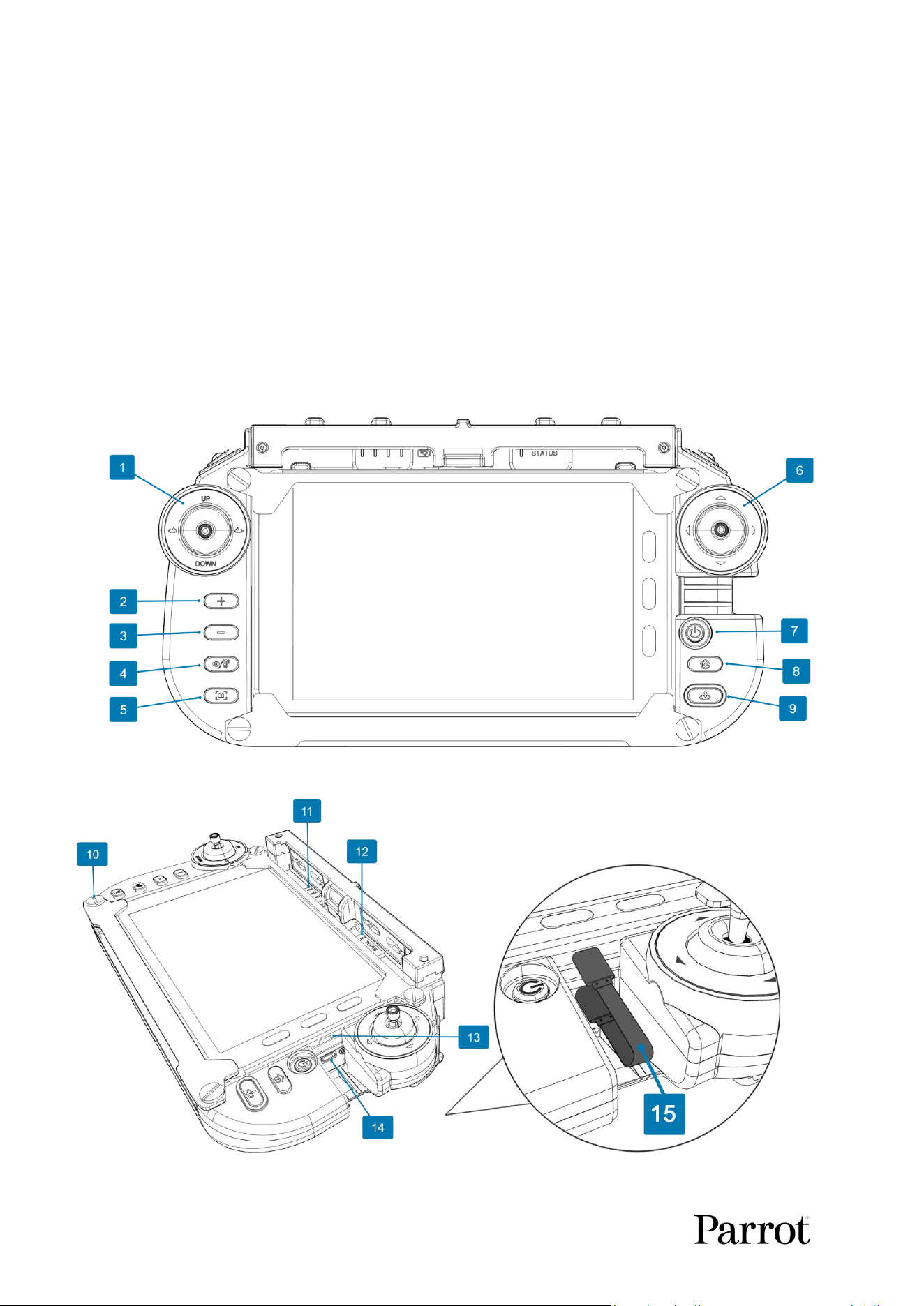
8. Skycontroller UKR
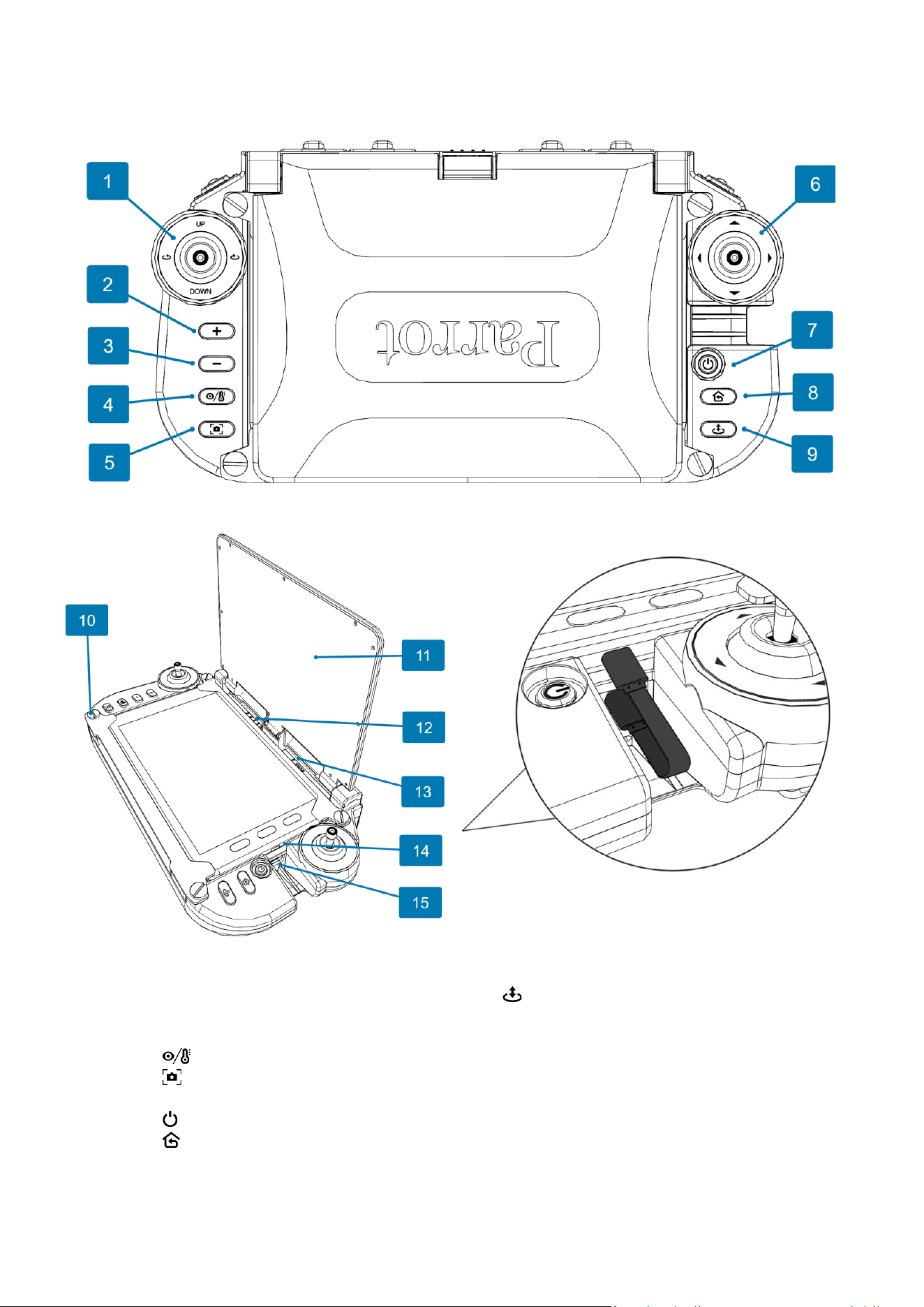
Figure 3: Skycontroller UKR top view closed
Figure 4: Skycontroller UKR open, showing USB-C to USB-C cable
1. Left joystick
9. Take-off / Land button
2. + EV button
10. Device retaining screw (1 of 4)
3. – EV button
11. Antenna
4. Thermal camera activation button
12. Skycontroller UKR battery status LEDs
5. Screenshot button
13. Top charge level LED indicators
6. Right joystick
14. Tablet USB-C port
7. Power button
15. USB-C Device connection port
8. RTH (Return to Home) button
16. USB-C to USB-C cable
NOTE: The USB-C to USB-C cable which connects the tablet to Skycontroller UKR comes preinstalled.
12
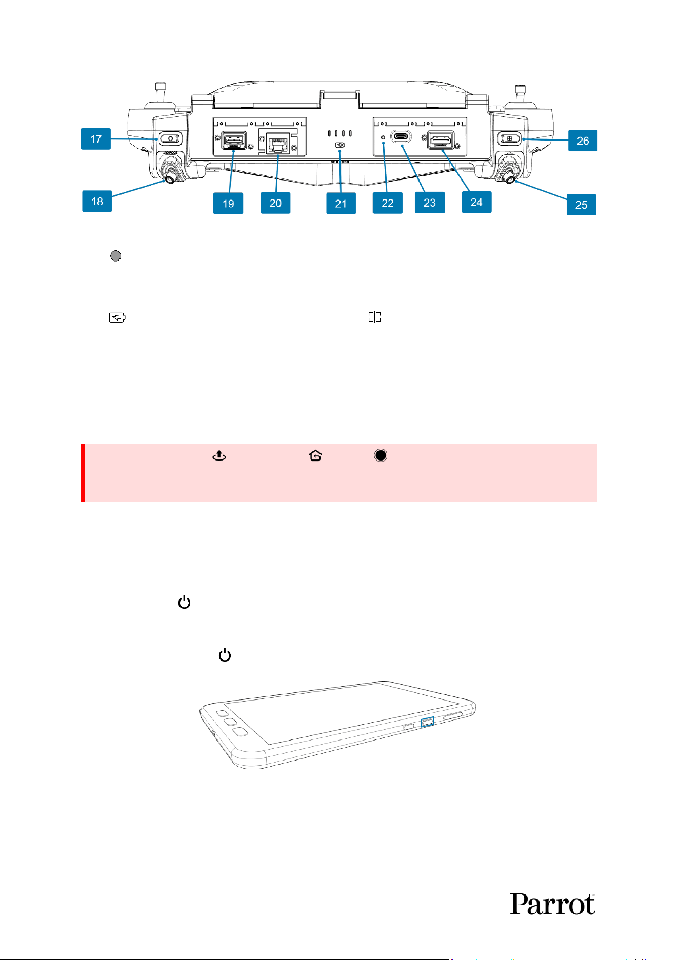
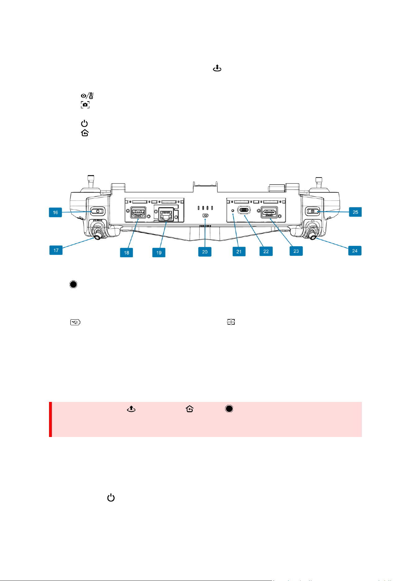
Figure 5: Skycontroller UKR rear view, plasc covers removed
17. Shutter (photo) or Start / Stop recording
22. Factory reset button
18. Zoom trigger (right)
23. USB-C charging port
19. USB-A port
24. HDMI port
20. Ethernet port
25. Gimbal tilt trigger (left)
21. Rear Charge level LED indicators
26. Reset camera (Zoom and gimbal tilt)
NOTE: Nos. 19, 20, 22, 23, and 24 (Figure 5) are underneath the 4 plasc covers on Skycontroller UKR.
The plasc covers are not shown in the image above for clarity.
The device on Skycontroller UKR is held in place by 2 brackets and 4 screws (No. 10 in Figure 4). The
device can be removed or replaced by unscrewing the screws and liing the device out of Skycontroller
UKR.
The Skycontroller UKR baery charging me is 2 hours.
4 LEDs show the charging status.
The LEDs turn o when charging is complete.
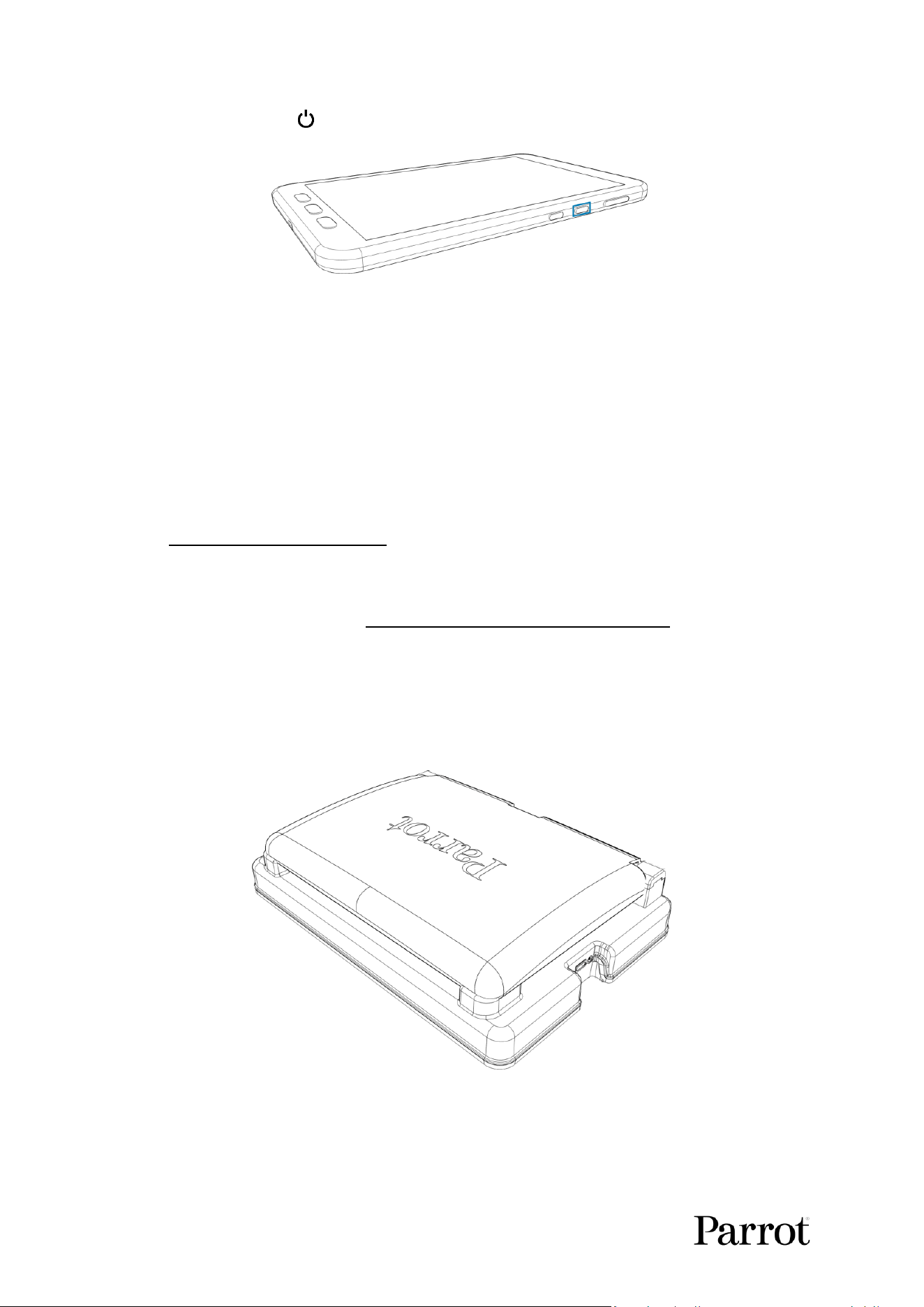
Press and hold the Power buon (No. 7 in Figure 3) for 2 seconds to turn on the Skycontroller UKR.
The 4 green LEDs turn on one aer the other.
Press and hold the tablet’s Power buon to turn on the tablet.
Figure 6: Skycontroller UKR's Android tablet showing the power buon
WARNING: If you press Take-O/Land, RTH, and Shuer simultaneously, the
EMERGENCY MODE on the aircra acvates immediately. EMERGENCY MODE instantly cuts
power to all motors on the aircra, which causes the drone to fall from the sky.
S K Y C O N T R O L L E R UKR
13
© 2026 Parrot Drones SAS. All Rights Reserved.
8.1. Connecvity
Skycontroller UKR has the following connectors:
• USB-A port (No. 19 in Figure 5) – used for drone/controller pairing
• Ethernet port (No. 20 in Figure 5) – used for remote antenna connecon, webserver access
• USB-C charging port (No. 23 in Figure 5) – used for charging
• HDMI port (No. 24 in Figure 5) – used for video output
8.2. HDMI video output
Use an HDMI-to-HDMI cable to connect the Skycontroller UKR to an external screen (or VR goggles).
The screen displays the aircras’s video stream.
NOTE: External screens only display the drone’s video stream, and none of the addional informaon
provided by FreeFlight 8. Operators can watch the drone’s view on an external screen, while they
navigate FreeFlight 8 menus (sengs or dashboard) on the device associated to the Skycontroller
UKR.
TIP: Use a cered HDMI-to-HDMI cable (not included in the box) to connect external pieces of
equipment to the Skycontroller UKR. Uncered cables may lead to display issues.
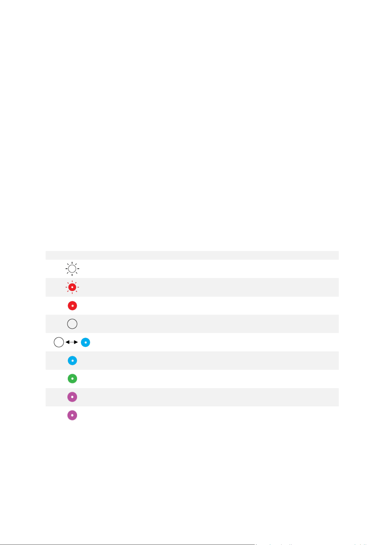
8.3. LED status indicator color codes
When the Skycontroller UKR is powered on, its status LED indicator (No. 13 in Figure 4) and its charging
LED (No. 12 in Figure 4, No. 21 in Figure 5) provide an instant visual indication:
Status LED indicator colors and behavior
White
Flashing
Controller is boong
Red
Flashing
Power-o buon is pressed
Red
Steady
Power-o buon held for 2 seconds, controller will power-o
White
Fade
Controller is booted, no acve drone
White/Blue
Fade
Controller is trying to connect to a drone
Blue
Steady
Controller is connected to a drone
Green
Fade
Controller is connected to a drone by USB cable and is in pairing
state
Magenta
Fade
Controller has lost MARS connecon and is trying to connect on
the backup radio link
Magenta
Steady
Controller has lost MARS connecon and is receiving drone
telemetry through backup radio
8.4. Pairing the aircra to a Skycontroller UKR
The aircra must be paired with the Skycontroller UKR in order to connect. Aer the aircra and
controller are paired, they remember each other. Follow this procedure to pair an aircra and a
controller for the rst me, and to restore the lost pairing between an aircra and a controller.
14
1. Power on the aircra.
2. Press Power on the Skycontroller UKR.
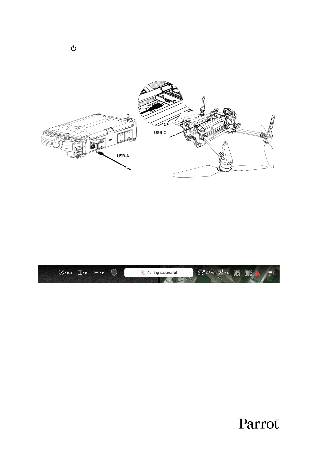
3. When both the aircra and Skycontroller UKR have booted, connect the aircra and the
controller with a USB cable (USB-A connecon to the USB-A port under the controller’s plasc
cover, USB-C connecon to the drone).
Figure 7: Pairing the drone with the controller
NOTE: Ensure that you connect the aircra via the USB-C port on the underside of the drone, not the
USB-C port on the baery.
The Skycontroller UKR status LED blinks green to indicate it acknowledges the aircra, and to establish
pairing protocols.
4. Wait for synchronizaon between Skycontroller UKR and the aircra.
The status LED turns solid blue when the aircra and the controller are connected, and FreeFlight 8
displays a message Pairing successful.
Figure 8: Pairing successful
5. Verify that the le trigger of the Skycontroller UKR acvates the aircra’s gimbal to ensure the
synchronizaon is complete.
6. Disconnect the USB cable between Skycontroller UKR and aircra.
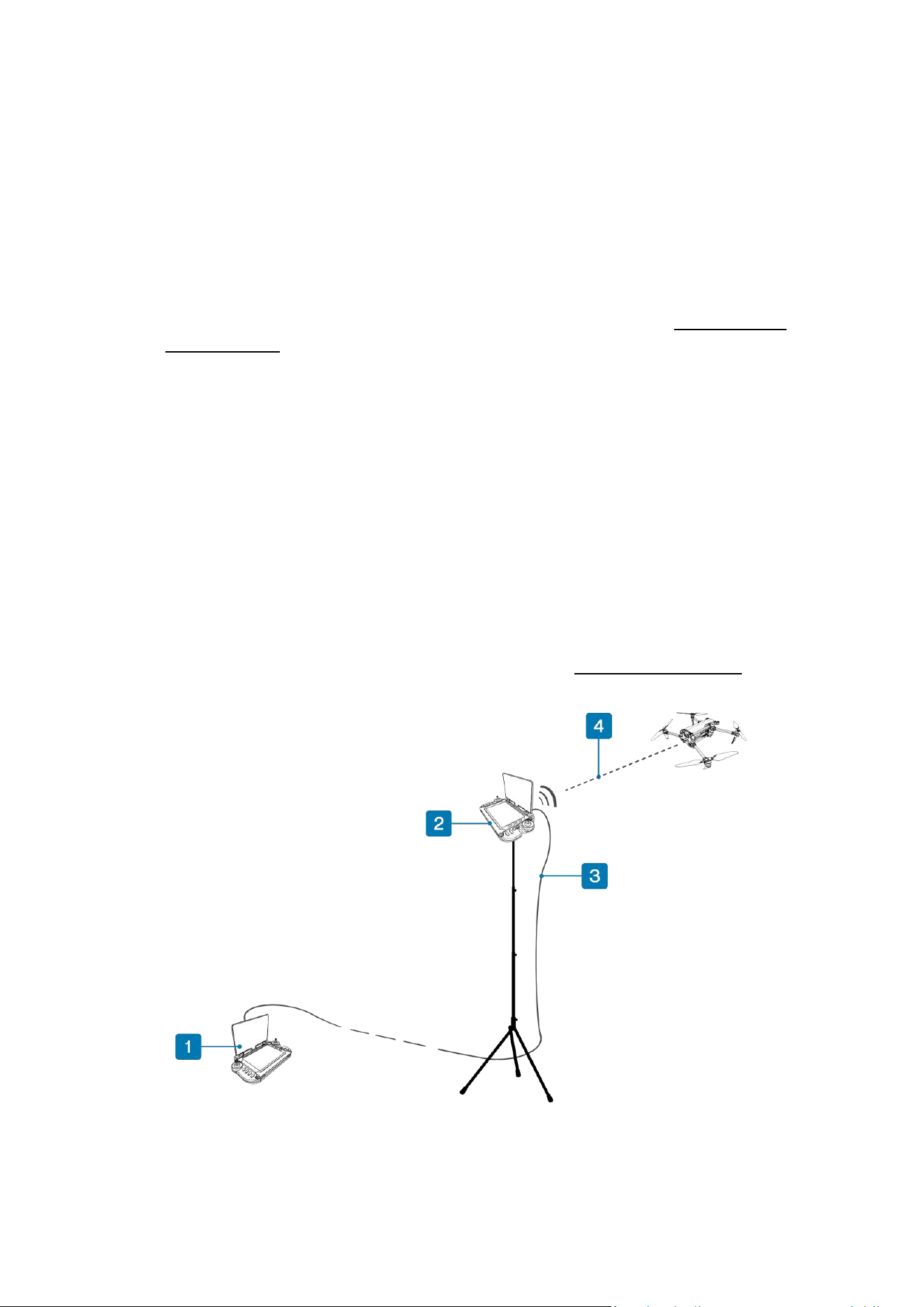
8.5. Remote antenna feature with a second Skycontroller UKR
Skycontroller UKR’s remote antenna feature allows the drone pilot to be in one locaon and a remote
antenna to be in a second locaon. This feature requires:
• A main (pilong) Skycontroller UKR used to pilot the drone.
• An RJ45 ethernet cable up to 100 m (328 ) long (minimum classicaon Cat5).
• A second (remote antenna) Skycontroller UKR.
This allows the drone pilot to control the drone indoors, or in a vehicle for example, with an external
antenna xed outdoors for opmal radio link performance. The remote antenna Skycontroller UKR can
be powered ON and powered OFF remotely via the main (pilong) Skycontroller UKR.
S K Y C O N T R O L L E R UKR
15
© 2026 Parrot Drones SAS. All Rights Reserved.
Follow this procedure to connect the remote antenna Skycontroller UKR:
1. Ensure that the main Skycontroller UKR and the remote antenna Skycontroller UKR are
powered o.
2. Connect the main Skycontroller UKR and the remote antenna Skycontroller UKR via an RJ45
cable.
NOTE: The RJ45 ethernet cable must be at least Cat5 and must not exceed 100 m (328 ) in length.
3. Power on the main Skycontroller UKR.
4. Acvate the Use remote antenna seng in FreeFlight 8 sengs. Refer to chapter 13.15.1.
Remote antenna for more informaon.
The MARS link radio of the main Skycontroller UKR disconnects. The remote antenna Skycontroller
UKR powers on.
NOTE: The remote antenna Skycontroller UKR status LED remains switched o
5. Wait several seconds before the status LED of the main Skycontroller UKR turns solid blue.
The main Skycontroller UKR now uses the MARS link radio and the LoRa of the remote antenna
Skycontroller UKR.
NOTE: When using a second Skycontroller UKR as a remote antenna, the tablet is not required for the
remote Skycontroller UKR.
The remote antenna Skycontroller UKR can be aached to a tripod using a standard UNC ¼” screw. An
addional accessory (MARS Orbiter) is available which rotates the remote Skycontroller UKR on a tripod
to ensure that it always faces the aircra’s direcon. Refer to chapter 15. Accessories for more
informaon.
Figure 9: Skycontroller UKR used as a remote antenna
1. Main (piloting) Skycontroller UKR
3. Cat5 RJ45 ethernet cable
2. Remote Skycontroller UKR
4. MARS radio link
16
9. Skycontroller UKR Mission
The ANAFI UKR mission pack includes a Skycontroller UKR Mission. Skycontroller UKR Mission is a
Skycontroller UKR without a radio or antenna. It is designed to be connected with a remote antenna.
Skycontroller UKR’s remote antenna feature allows the drone pilot to control the drone from indoors
with an external antenna xed outdoors for opmal radio link performance. The remote antenna
Skycontroller UKR can be powered ON and powered OFF remotely via the main (pilong) Skycontroller
UKR.
This feature requires:
• A main (pilong) Skycontroller UKR or Skycontroller UKR Mission used to pilot the drone.
• An RJ45 ethernet cable up to 100 m (328 ) long (minimum classicaon Cat5).
• A second Skycontroller UKR or MARS Ranger acng as the remote antenna.
Figure 10: Skycontroller UKR Mission top view
Figure 11: Skycontroller UKR Mission, showing USB-C to USB-C cable
S K Y C O N T R O L L E R UKR
17
© 2026 Parrot Drones SAS. All Rights Reserved.
1. Left joystick
9. Take-off / Land button
2. + EV button
10. Device retaining screw (1 of 4)
3. – EV button
11. Skycontroller UKR battery status LEDs
4. Thermal camera activation button
12. Top charge level LED indicators
5. Screenshot button
13. Tablet USB-C port
6. Right joystick
14. USB-C Device connection port
7. Power button
15. USB-C to USB-C cable
8. RTH (Return to Home) button
NOTE: The USB-C to USB-C cable which connects the tablet to Skycontroller UKR Mission comes
preinstalled.
Figure 12: Skycontroller UKR Mission rear view, plasc covers removed
NOTE: Nos. 18, 19, 21, 22, and 23 (Figure 12) are underneath the 4 plasc covers on Skycontroller UKR.
The plasc covers are not shown in the image above for clarity.
The device on Skycontroller UKR Mission is held in place by 2 brackets and 4 screws (No. 10 in Figure
11). The device can be removed or replaced by unscrewing the screws and liing the device out of
Skycontroller UKR Mission.
The Skycontroller UKR Mission baery charging me is 2 hours.
4 LEDs show the charging status.
The LEDs turn o when charging is complete.
Press and hold the Power buon (No. 7 in Figure 10) for 2 seconds to turn on the Skycontroller UKR
Mission.
The 4 green LEDs turn on one aer the other.
16. Shutter (photo) or Start / Stop recording
21. Factory reset button
17. Zoom trigger (right)
22. USB-C charging port
18. USB-A port
23. HDMI port
19. Ethernet port
24. Gimbal tilt trigger (left)
20. Rear Charge level LED indicators
25. Reset camera (Zoom and gimbal tilt)
WARNING: If you press Take-O/Land, RTH, and Shuer simultaneously, the
EMERGENCY MODE on the aircra acvates immediately. EMERGENCY MODE instantly cuts
power to all motors on the aircra, which causes the drone to fall from the sky.
18
Press and hold the tablet’s Power buon to turn on the tablet.
Figure 13: Skycontroller UKR Mission's Android tablet showing the power buon
9.1. Connecvity
Skycontroller UKR Mission has the following connectors:
• USB-A port (No. 18 in Figure 12) – used for drone/controller pairing, drone update.
• Ethernet port (No. 19 in Figure 12 – used for remote antenna connecon, webserver access.
• USB-C charging port (No. 22 in Figure 12) – used for charging.
• HDMI port (No. 23 in Figure 12) – used for video output.
9.2. HDMI video output
Skycontroller UKR Mission has the same HDMI video output feature as a standard Skycontroller UKR.
Refer to chapter 8.2. HDMI video output for more informaon.
9.3. LED status indicator color codes
Skycontroller UKR Mission and MARS RANGER have the same LED status indicator feature as a
standard Skycontroller UKR. Refer to chapter 8.3. LED status indicator color codes for more
informaon.
9.4. MARS Ranger
MARS Ranger is a dedicated remote antenna system based on Skycontroller UKR without the pilong
interface (MARS Ranger does not include a tablet, the FreeFlight 8 applicaon, or the pilong
buons).
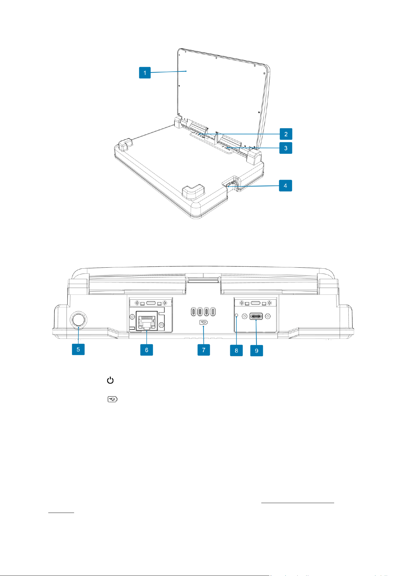
Figure 14: MARS Ranger
S K Y C O N T R O L L E R UKR
19
© 2026 Parrot Drones SAS. All Rights Reserved.
Figure 15: MARS Ranger open
1. Antenna
3. Top charge level LED indicators
2. MARS Ranger battery status LEDs
4. USB-C port
Figure 16: MARS Ranger rear view, plasc covers removed
5. Power button
8. Factory reset button
6. Ethernet port
9. USB-C charging port
7. Rear Charge level LED indicators
MARS Ranger has the following connectors:
• Ethernet port (No. 6 in Figure 16) – used for remote antenna connecon, webserver access.
• USB-C charging port (No. 8 in Figure 16) – used for charging.
NOTE: Numbers 6, 8, and 9 (Figure 16) are underneath the 2 plasc covers on MARS Ranger. The
plasc covers are not shown in the image above for clarity.
When the Use Remote Antenna toggle is set to Yes in FreeFlight 8, MARS Ranger turns on
automacally if it has been acvated in the previous 3 hours. Refer to chapter 13.15.1 Remote
Antenna for more informaon.
20
If MARS Ranger has not been acvated in the previous 3 hours, it goes into deep sleep mode and
must be re-acvated so that auto power on is enabled again.
To acvate MARS Ranger, perform 1 of the following acons:
• A long press on MARS Ranger’s power buon to power on MARS Ranger.
• A short press on MARS Ranger’s power buon to enable Wake-on-Lan.
• Connect MARS Ranger via USB-C to a charger.
9.5. Pairing the aircra to a Skycontroller UKR Mission
Skycontroller UKR Mission and MARS Ranger allow the drone pilot to be in one locaon and the MARS
Ranger remote antenna to be in a second locaon. This feature requires:
• A Skycontroller UKR Mission used to pilot the drone.
• The provided RJ45 ethernet cable.
• A MARS Ranger.
This allows the drone pilot to control the drone indoors, or in a vehicle for example, with the MARS
Ranger xed outdoors for opmal radio link performance. MARS Ranger can be powered ON and
powered OFF remotely via Skycontroller UKR Mission.
The aircra must be paired with the Skycontroller UKR Mission in order to connect. Aer the aircra
and controller are paired, they remember each other. Follow this procedure to pair an aircra and a
controller for the rst me, and to restore the lost pairing between an aircra and a controller.
1. Ensure that the MARS Ranger is acvated (refer to chapter 9.4 MARS Ranger for more
informaon)
2. Connect the Skycontroller UKR Mission and the MARS Ranger via the provided RJ45 cable.
3. Power on the Skycontroller UKR Mission.
The MARS Ranger automacally powers on; the MARS Ranger status LED is switched o.
4. Power on the aircra.
5. Connect the aircra and the Skycontroller UKR Mission with a USB cable (USB-A connecon to
the USB-A port under the Skycontroller UKR Mission plasc cover, USB-C connecon to the
drone).
NOTE: Ensure that you connect ANAFI UKR via the USB-C port on the underside of the drone, not the
USB-C port on the baery
The Skycontroller UKR Mission status LED blinks green to indicate it acknowledges the aircra, and to
establish pairing protocols.
6. Wait for synchronizaon between Skycontroller UKR Mission and the aircra.
The status LED turns solid blue when the aircra and the Skycontroller UKR Mission are connected,
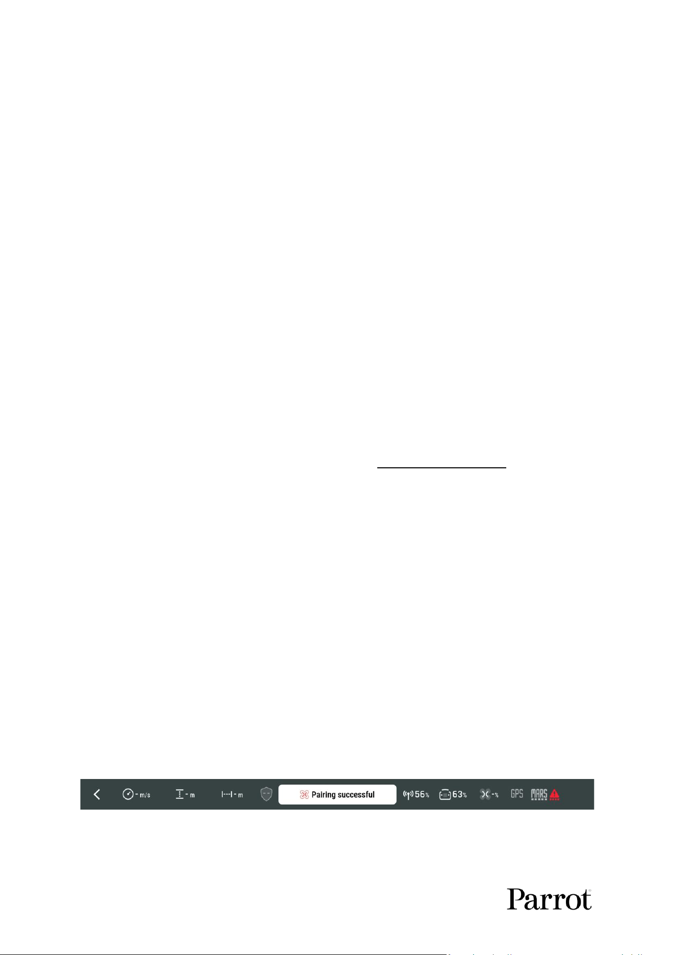
and FreeFlight 8 displays a message Pairing successful.
Figure 17: Pairing successful – remote antenna icon
7. Verify that the le trigger of the Skycontroller UKR Mission acvates the aircra’s gimbal to
ensure the synchronizaon is complete.
S K Y C O N T R O L L E R UKR
21
© 2026 Parrot Drones SAS. All Rights Reserved.
8. Disconnect the USB cable between Skycontroller UKR Mission and aircra
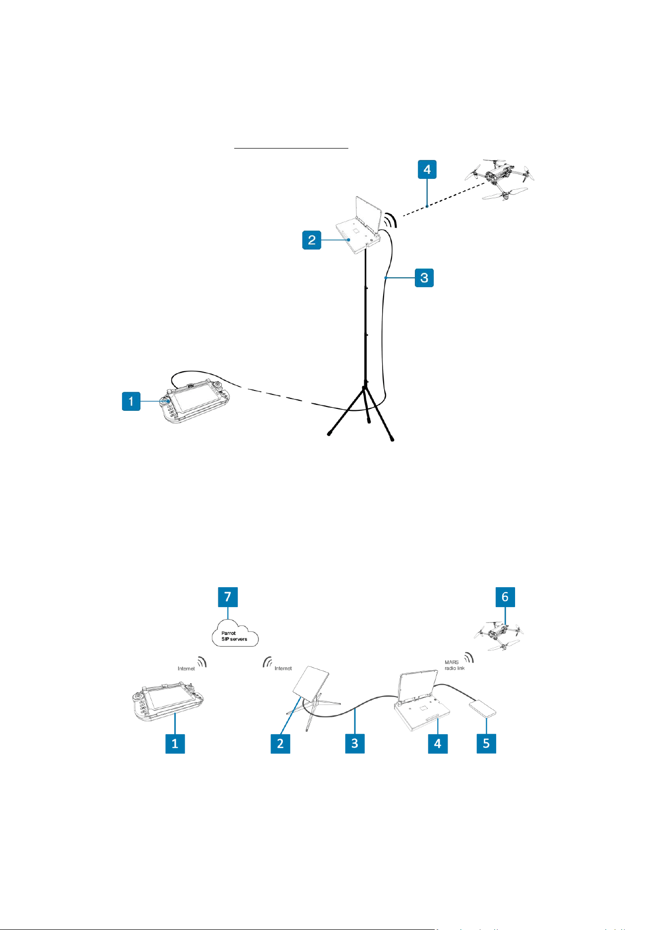
The MARS Ranger can be aached to a tripod using a standard UNC ¼” screw. An addional accessory
(MARS Orbiter) is available which rotates the MARS Ranger on a tripod to ensure that it always faces
the aircra’s direcon. Refer to chapter 15. Accessories for more informaon.
Figure 18: MARS Ranger used as a remote antenna
1. Skycontroller UKR Mission
3. Cat5 RJ45 ethernet cable
2. Remote MARS Ranger
4. MARS radio link
9.6. Cloud antenna
The Skycontroller UKR Mission can remotely connect to the MARS Ranger via an internet network,
eliminang the need for an Ethernet cable.
Figure 19: MARS Ranger as a remote antenna using Starlink Mini
1. Skycontroller UKR Mission
5. Power bank
2. Starlink Mini
6. ANAFI UKR
3. Ethernet cable
7. Parrot SIP servers
4. MARS Ranger
22
9.6.1. Prerequisites
The cloud antenna feature requires:
• An internet connecon on the tablet connected to Skycontroller UKR Mission.
• A MARS Ranger paired at least once with a FreeFlight 8 user account. To pair the MARS
Ranger:
a. Power on MARS Ranger.
b. Connect the tablet running FreeFlight 8 to the MARS Ranger via the USB-C port.
NOTE: The FreeFlight 8 account can be a Parrot cloud account or an anonymous account.
• An aircra paired at least once with the Skycontroller UKR Mission. Refer to chapter 9.5
Pairing the aircra to a Skycontroller UKR Mission for more informaon.
Aer the MARS Ranger is paired with FreeFlight 8 user account, it can be connected to the
Skycontroller UKR. It is able connect if it is switched on or switched o but connected to a power
bank:
1. Connect MARS Ranger to a power bank via the USB-C charging port (only required if MARS
Ranger is switched o).
2. Connect the MARS Ranger to the internet.
NOTE: You can use a Starlink system to connect MARS Ranger to the internet.
MARS Ranger registers with the Parrot server as soon as it connects to the internet.
Aer MARS Ranger registers with the Parrot server, it becomes visible as a cloud antenna on the
FreeFlight 8 Remote Antenna screen under Select your remote antenna.
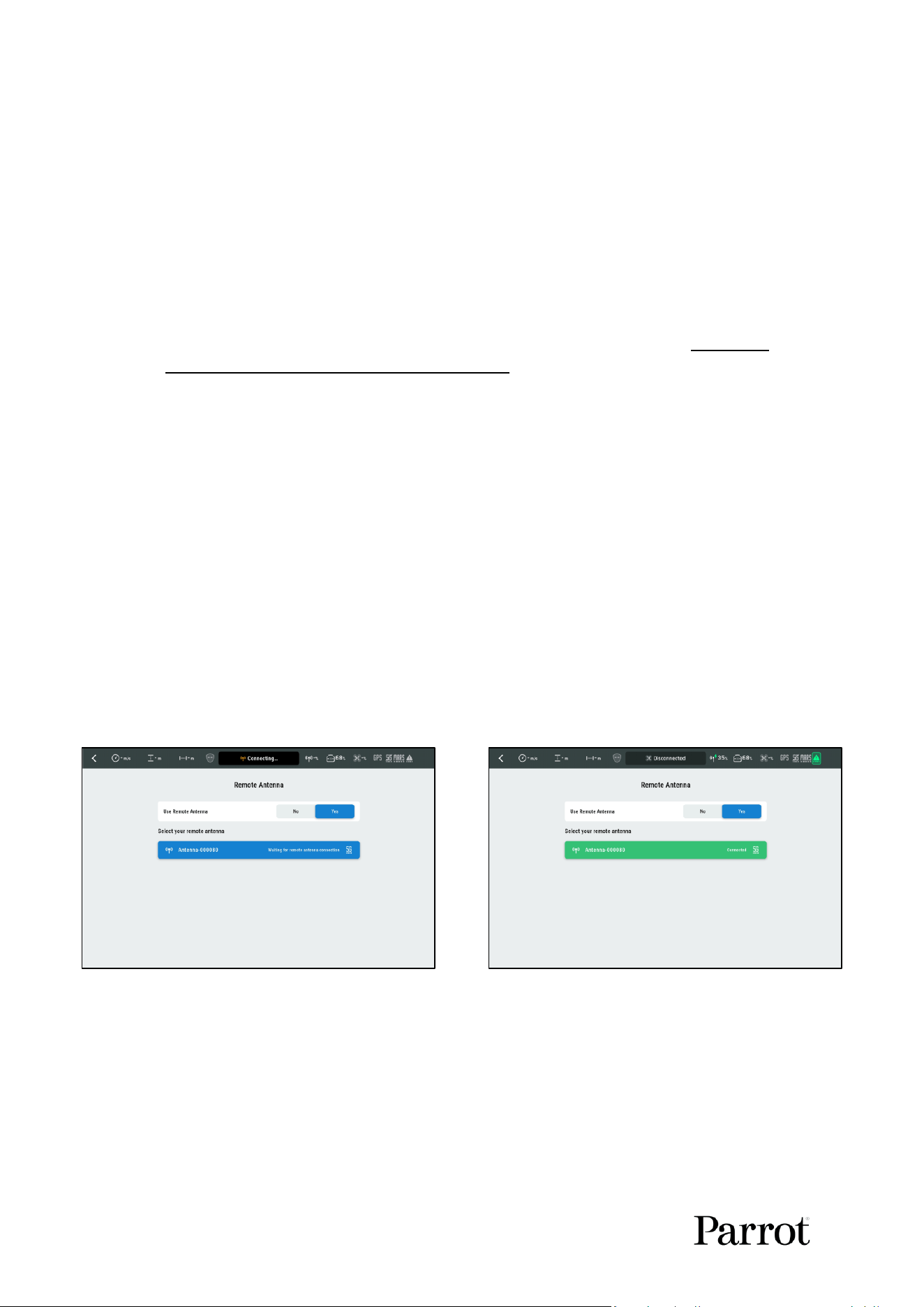
3. Tap the cloud antenna.
The cloud antenna connects aer a few seconds:
Figure 20: Cloud antenna connecon
Aer the cloud antenna connects to FreeFlight 8, the baery level of the cloud antenna displays in the
FreeFlight 8 top bar.
S K Y C O N T R O L L E R UKR
23
© 2026 Parrot Drones SAS. All Rights Reserved.
10. Pilong basics
The user has 2 opons for taking o: ground take-o or hand launch.
10.1. Ground Take-o
1. Turn on the drone and the controller.
2. Posion the drone on a at, even, and clear surface.
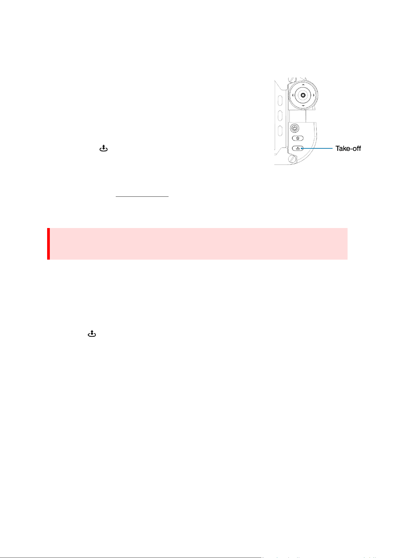
For opmal performance, Parrot recommends that you use the launch pad
for ground take-o.
The video stream of the camera is visible on the tablet.
3. Press the Take-o / Land buon on Skycontroller UKR.
4. The drone takes o and hovers 1 m / 3 above the take-o point.
10.2. Hand launch
Hand launch is enabled by default in FreeFlight 8. However, it can be disabled from the RTH and Safety
settings page (Refer to chapter 13.5. RTH for more information).
You can perform the hand launch procedure alone. However, Parrot recommends that you work as a
team of 2 people.
Pay attention to the wind direction and speed. Do not face the wind. Keep yourself at a safe distance
from the drone considering the possibility of drifting with the wind.
1. Power on the drone.
2. Position the drone on your flat, open hand.
The Handlaunch AVAILABLE interface opens on FreeFlight 8.
3. Press Take-off / Land on the Skycontroller UKR, or tap Start on the FreeFlight 8 Handlaunch
interface.
The Hand launch STARTING message appears on FreeFlight 8. The drone’s propellers start to rotate
slowly, and a 3-second countdown timer starts with a hand animation. When the timer reaches 0, the
message LAUNCH appears.
NOTE: You can abort the hand launch procedure at any time before you launch the drone by tapping
Stop.
4. Throw the drone up and forward with your open hand. Aim for 1 meter in front of you.
The drone becomes airborne. It stabilizes and waits for commands from the pilot.
CAUTION: Certain environments are not suitable for ground take-o, and so the hand launch
procedure must be used. Use hand launch in the following environments:
• Sandy environments
• Wet or snowy ground
• Tall grass
WARNING: Do not aempt a hand launch procedure if FreeFlight 8 does not display the
Handlaunch AVAILABLE interface. Do not obstruct the downward facing camera, or any of the
sensors underneath the drone.
24
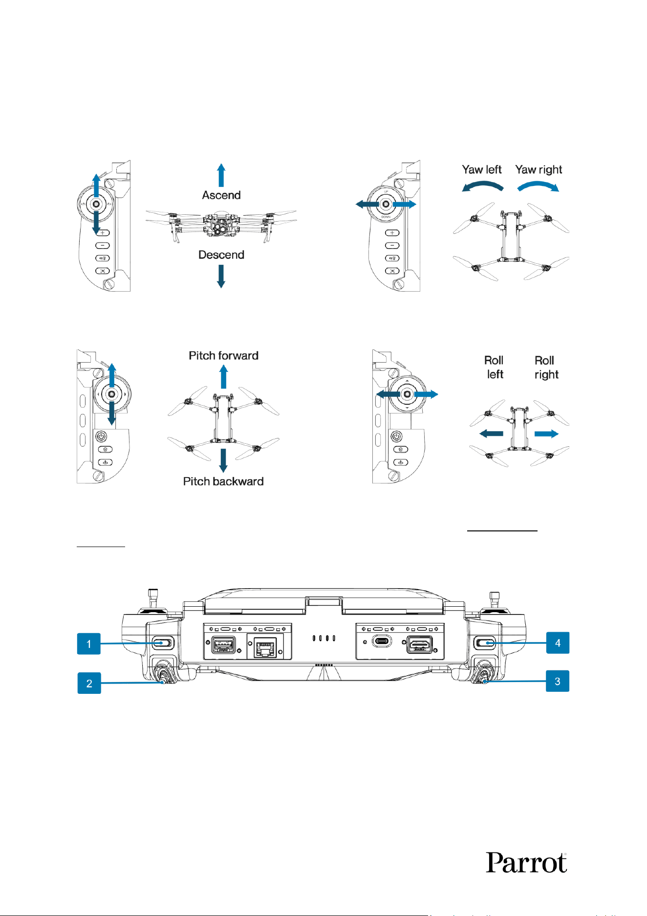
10.3. Flying
Flying is controlled with the joyscks. Skycontroller UKR has 2 buon conguraons. Mode 2 is the
default conguraon.
Le joysck (mode 2)
Figure 21: Le joysck
Right joysck (mode 2)
Figure 22: Right joysck
For more informaon on how to change the buon conguraon mode, refer to chapter 13.15.
Controller.
10.4. Gimbal controls
Figure 23: Gimbal and camera controls
1. Shutter:
o In Video mode: stop and start recording.
o In Photo mode: take a picture.
3. Gimbal tilt:
o From 90° to -90°
2. Zoom:
o From x1 to x35
4. Reset camera:
o Reset the zoom to x1.
o Place the gimbal horizontally.
S K Y C O N T R O L L E R UKR
25
© 2026 Parrot Drones SAS. All Rights Reserved.
10.4.1. Advanced zoom controls
You can control the zoom using short or long full-lt presses on the zoom joysck (No. 2 in Figure 23):
• Short full-lt press (less than 0.4 seconds): skips up or down to the closest zoom level preset
• Long full-lt press (more than 0.4 seconds): skips up or down to the extreme zoom level
preset
The available zoom level presets are:
• Minimum Wide: Minimum zoom of the wide-angle camera
• Minimum Thermal: Minimum zoom of the thermal camera (available in Thermal mode only)
• Minimum Telephoto: Minimum zoom of the telephoto camera
• Maximum Telephoto: Maximum zoom of the telephoto camera
10.5. Landing
Press the Take-o / Land buon at any altude to land the drone.
Press the Take-o / Land buon a second me to abort the landing process at any me during the
landing.
Alternavely, the user can also land the drone by ying the drone to minimum altude (1 m /3.3
above the ground) and maintaining the le joysck in the down direcon for 3 seconds.
An animaon is displayed in the FreeFlight 8 HUD during the landing phase:
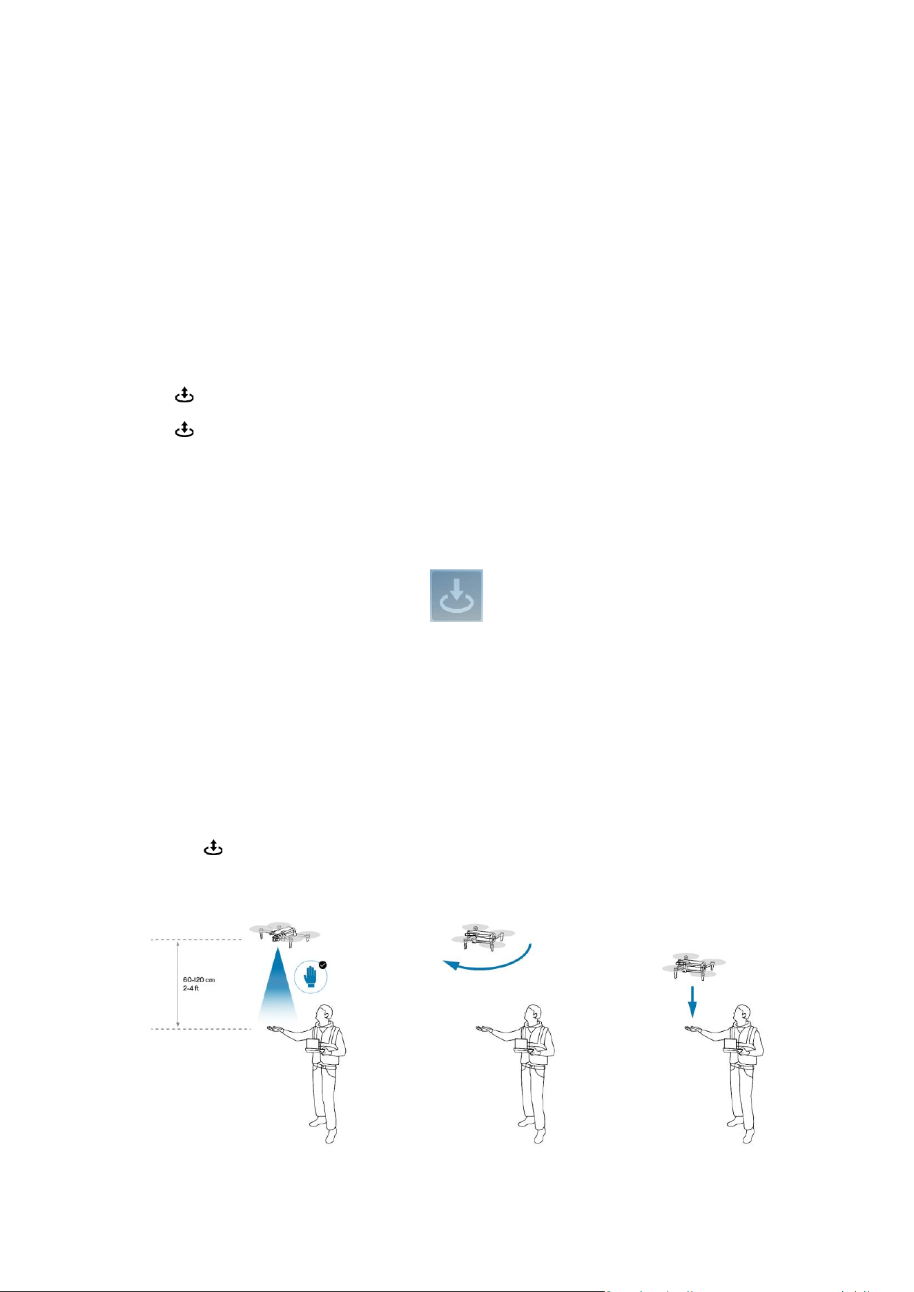
10.6. Hand Landing
In some environments such as sand, snow or tall grass, it is preferable to land in the pilot’s hand rather
than on the ground.
The Hand Landing procedure initiates if the aircraft detects a hand during the landing phase. The
aircraft software runs a vision algorithm on the bottom stereo camera images to detect a hand.
The procedure to initiate a hand land is described below:
1. Fly the aircraft at least 1 m (3 ft) directly over your open hand, with your arm extended.
2. Press Take-off / Land.
3. If necessary, the aircraft rotates to align perfectly with your hand.
4. The aircraft slowly and safely lands on your hand
Figure 24: Hand landing procedure
26
NOTE: During a landing procedure, if the aircra is sll ying at more than 100 cm (3 ) from your
hand, you can extend your arm under the aircra, with your hand open. The aircra recognizes your
hand and proceeds with the hand landing described above.
You can perform the hand landing procedure alone. However, Parrot recommends that you work as a
team of 2 people.
Do not attempt a hand landing in wind strong enough to make the aircraft fight to hold its hovering
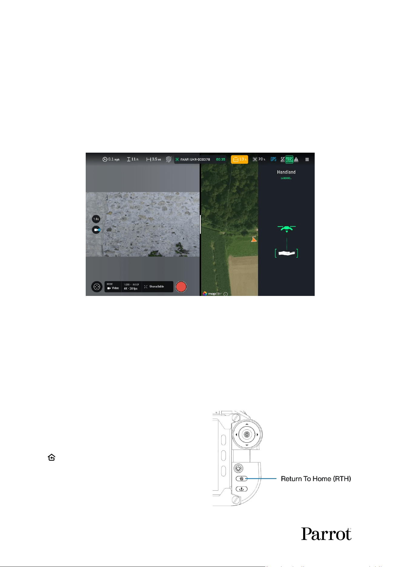
position. FreeFlight 8 displays a popup as soon as the drone detects your hand. For your safety, if the
hand has not been detected, it is recommended to remove your hand and let the drone land on the
ground.
Figure 25: Handland
You can perform the hand landing procedure alone. However, Parrot recommends that you work as a
team of 2 people.
Do not attempt a hand landing in wind strong enough to make the aircraft fight to hold its hovering
position.
Let the aircraft do the work. Do not forcefully grab the aircraft while it is hovering.
Pay attention to the wind direction and speed. Keep yourself at a safe distance from the drone
considering the possibility of drifting with the wind.
10.7. Return to Home
Return to Home is an important safety funcon. At
any me, the pilot can request the aircra to reach
its home posion by pressing the Skycontroller UKR’s
Return to Home buon.
3 opons are available in FreeFlight 8 seng for the
home posion:
1. Take-o posion
2. Pilot posion
S K Y C O N T R O L L E R UKR
27
© 2026 Parrot Drones SAS. All Rights Reserved.
3. Custom posion dened by the pilot
Refer to chapter 13.5. RTH for more informaon.
When the return to home procedure is underway, press the Return to Home buon again to
cancel the procedure.
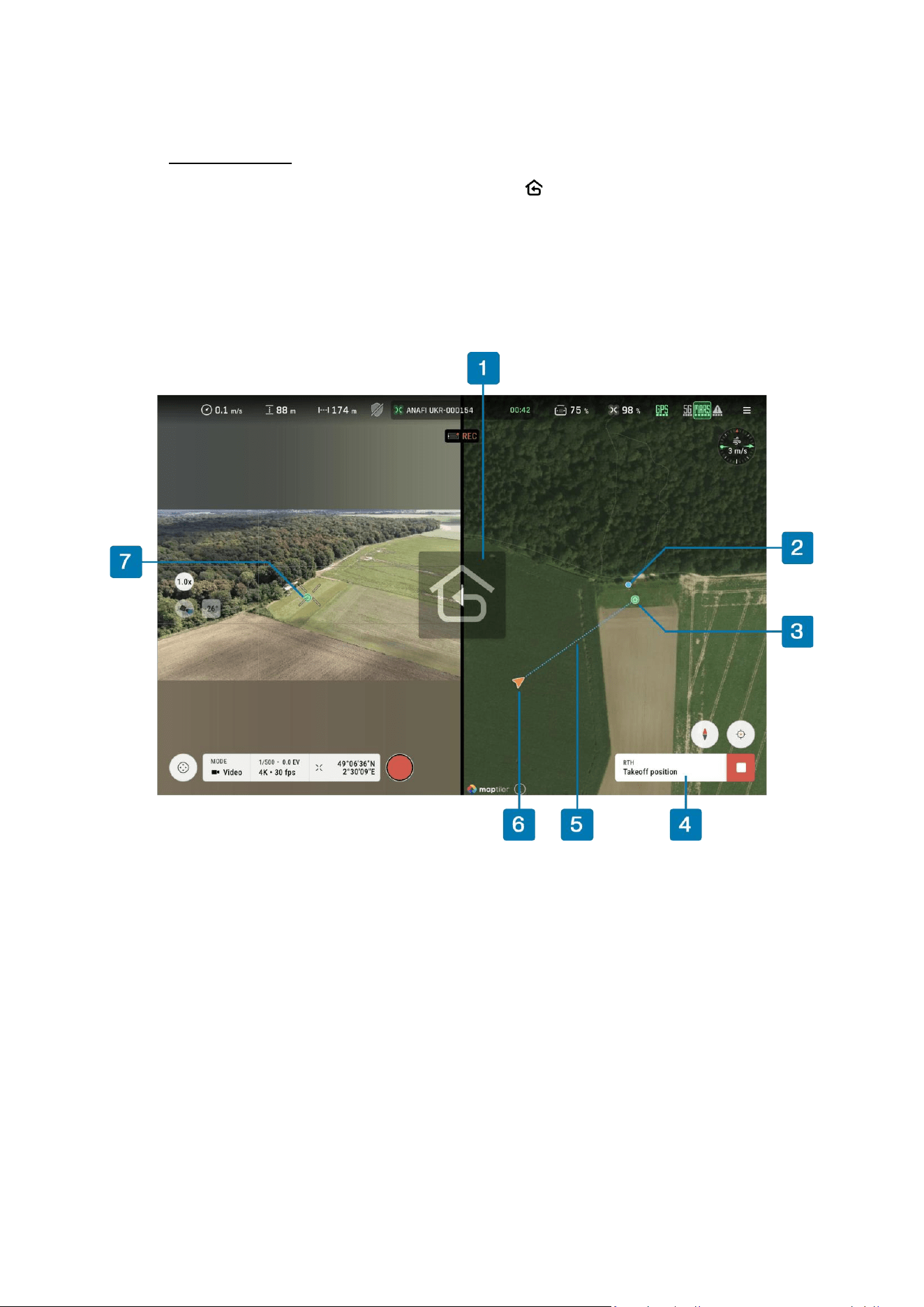
On the FreeFlight 8 display:
- A return to home reminder blinks in the center of the display.
- The return path is shown on the map.
- Tap Stop to cancel the Return to Home procedure.
Figure 26: Return to Home in progress
1. RTH animation
5. RTH return path
2. Map view Skycontroller UKR position
6. Aircraft position
3. Map view Home position
7. Streaming view Home position
4. RTH action bar with Stop button
28
11. FreeFlight 8
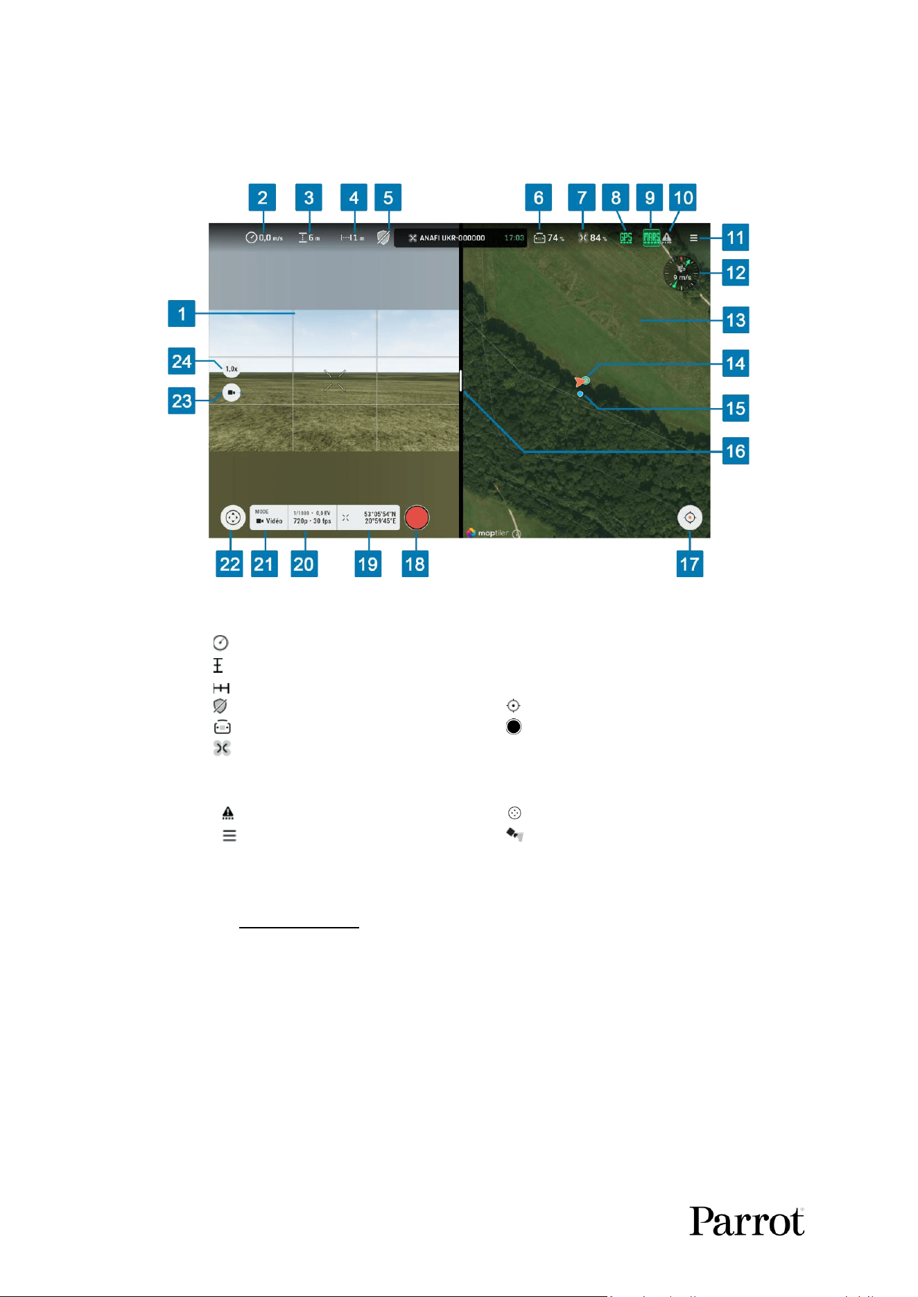
The FreeFlight 8 HUD (heads-up display) allows the user to control all aircra features from the
Skycontroller UKR screen.
Figure 27: FreeFlight 8 main HUD
1. Streaming view
13. Map view
2. Ground speed
14. Home point
3. ATO/ AMSL toggle
15. Skycontroller UKR position
4. Distance to home
16. Split view slider
5. Obstacle avoidance status
17. Map center toggle
6. Controller battery level
18. Recording status
7. Drone battery level
19. Cursor on Target
8. Navigation status
20. Exposure adjustments
9. MARS main radio status*
21. Image MODE
10. LoRa backup radio status
22. Flight mode selector
11. Settings
23. Gimbal pitch
12. Wind speed and direction
24. Zoom level
NOTE: You can toggle between Altude above take-o (ATO) and Altude above Mean Sea level
(AMSL) by tapping No. 3 in Figure 27.
The main view of FreeFlight 8 displays all the informaon and controls for every phase of ight.
The status bar at the top of the screen permanently shows the most important telemetry data.
* Available icons depend on individual conguraons.
The ight screen is split into two parts:
• The Streaming view (No. 1 in Figure 27),
• The Map view (No. 13 in Figure 27).
Drag the Split view slider (No. 16 in Figure 27) to the le or to the right to adjust the size of the
streaming view and the map view.
S K Y C O N T R O L L E R UKR
29
© 2026 Parrot Drones SAS. All Rights Reserved.
At the boom of the main ight view, users can select the ight mode (No. 22 in Figure 27), congure
imaging modes (No. 21 in Figure 27), and center the map view (No. 17 in Figure 27).
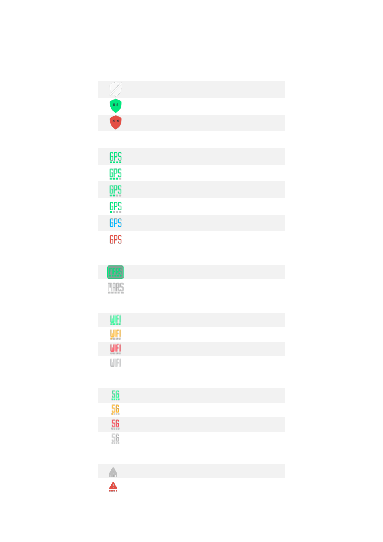
Obstacle avoidance status:
OA disabled by user
OA enabled by user and engaged by supervisor
OA enabled by user and disengaged by supervisor
Navigaon status:
GNSS navigaon (21 satellites or more)
GNSS navigaon (14-20 satellites)
GNSS navigaon (10-13 satellites)
GNSS navigaon (9 satellites or less)
Opcal navigaon
Aero navigaon
MARS (Military Adapve Radio System) main radio status:
Connected
Disconnected
Wi-Fi main radio status:
Connected
Connecon degraded
Connecon poor
Disconnected
Cellular radio main radio status:
Connected
Connecon degraded
Connecon poor
Disconnected
LoRa backup radio status:
Backup radio not in use
Backup radio conguraon error
30
Backup radio congured but no packet is exchanged
Controller and drone are exchanging packets
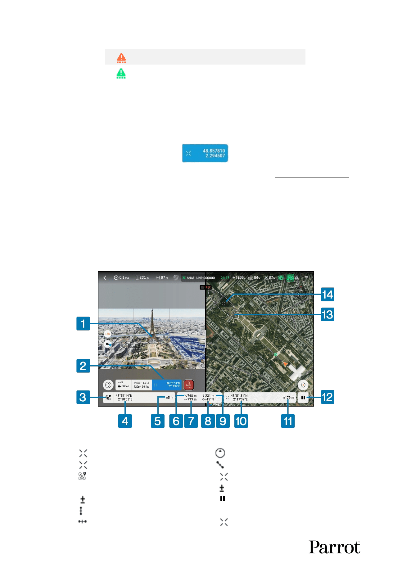
11.1. Cursor on Target
Cursor On Target displays the absolute coordinates of the point at the center of the streaming view.
This funcon works with or without GPS.
When Cursor On Target is acvated, click on the widget in the boom bar to display detailed
informaon about the target coordinates and distance to the drone.
The coordinates system can be changed in the Interface sengs (Refer to chapter 13.10. Interface for
more informaon).
In addion to the point coordinates, both the relave vercal and horizontal distance between the
drone and the center point are also displayed.
The center point is shown in the map view. The center point coordinates esmaon accuracy is
represented by an ellipse in the map if the Cursor On Target boom bar is deployed.
Cursor On Target is available in all Flight modes. In Tracking mode, if a target on the ground has been
selected, Cursor On Target displays the coordinates of the target.
Figure 28: Cursor on Target
1. CoT Reticle
8. Azimuth in relation to North
2. Target coordinates
9. Slant range
3. Aircraft/GCS coordinates toggle
10. Target coordinates
4. Drone coordinates
11. Target position accuracy
5. Drone position accuracy
12. Freeze coordinate updates
6. Drone vertical distance to target
13. Accuracy ellipse
7. Drone horizontal distance to target
14. CoT reticle in map view
S K Y C O N T R O L L E R UKR
31
© 2026 Parrot Drones SAS. All Rights Reserved.
Press and hold on the coordinates (Nos. 4 and 10 in Figure 28) to share the displayed data to third
party apps.
11.2. Landmarks
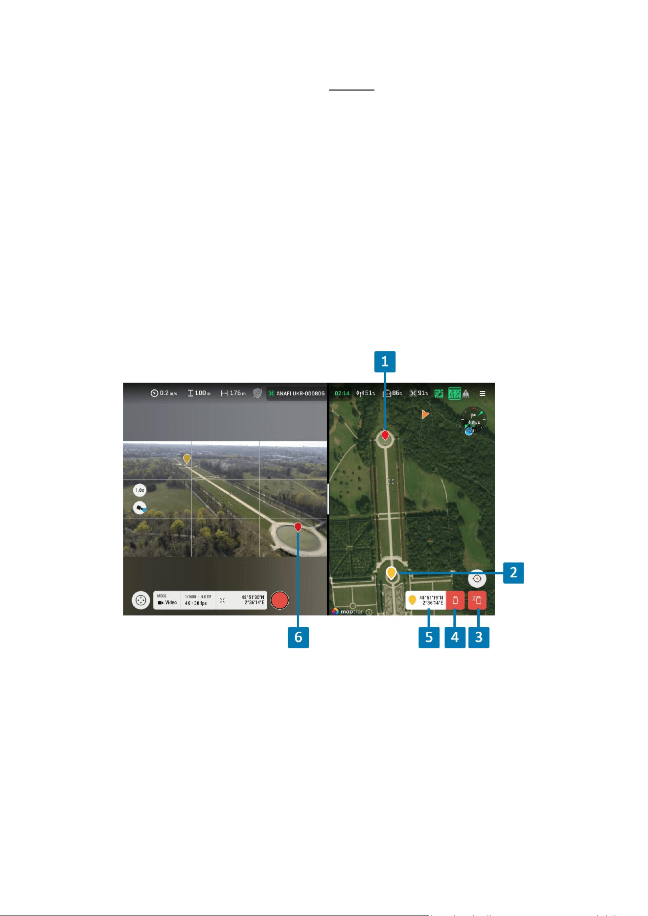
You can set a landmark with a long press in the FreeFlight 8 map view. Landmarks can be useful to
easily idenfy points of parcular interest in both the FreeFlight 8 map view and streaming view.
You can set a landmark with a long press in the map view.
FreeFlight 8 creates the landmark at ground level. To determine the ground elevaon at the landmark
locaon, FreeFlight 8 uses DTED maps if they are available on the drone. If not, it uses an internet
API. If neither is available, FreeFlight 8 uses the ground elevaon at the takeo locaon (at ground
assumpon).
You can move a landmark by dragging it in the map view.
You can select a landmark by tapping it in the map view. The coordinates of the selected landmark
are indicated. The selected landmark can be deleted by tapping on the bin buon close to its
coordinates.
Figure 29: Landmarks
1. Landmark (map view)
5. Selected landmark coordinates
2. Selected landmark (map view)
6. Landmark (streaming view)
3. Delete all landmarks
4. Delete selected landmark
32
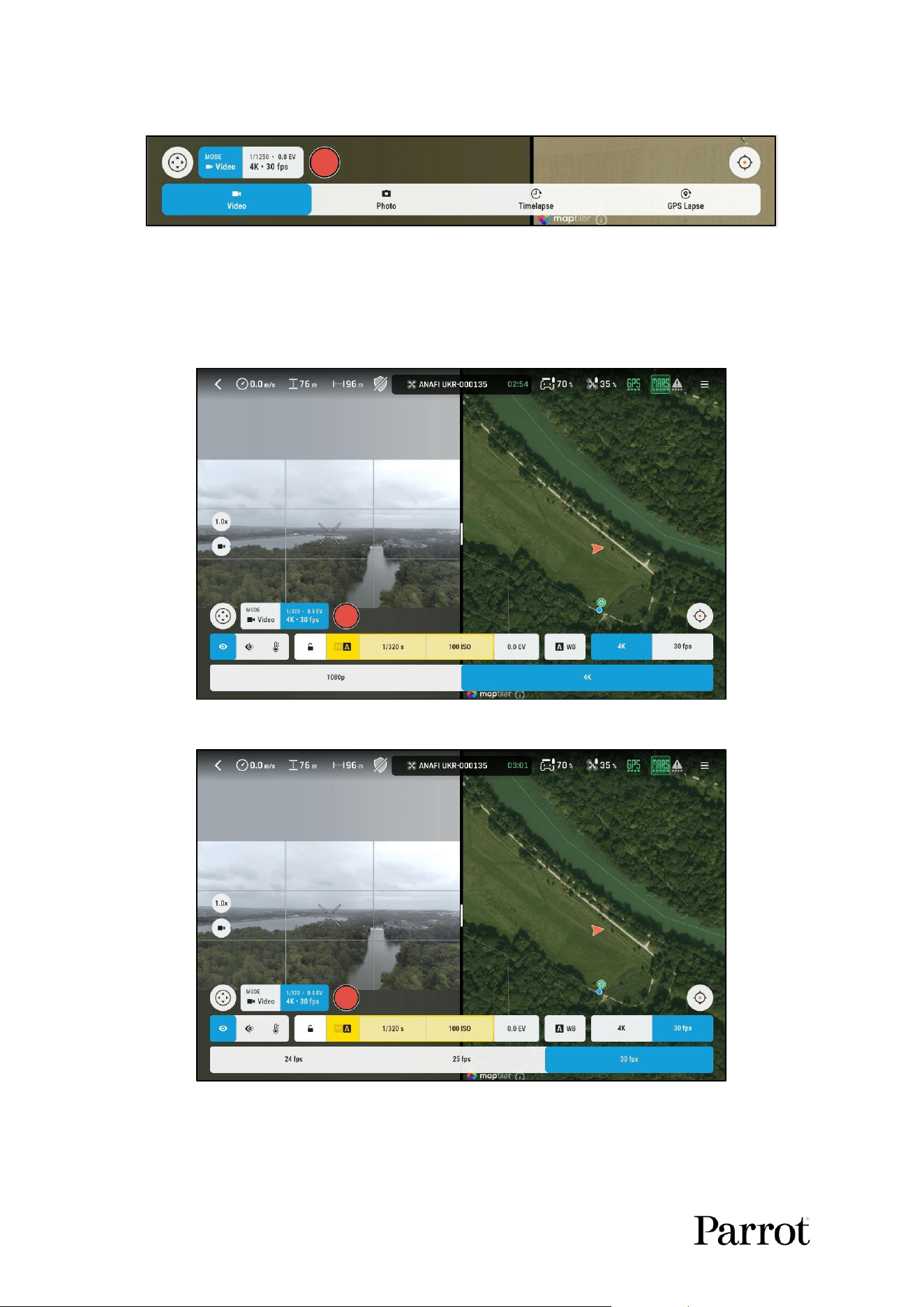
11.3. Image mode
Figure 30: Video and photo modes
Four imaging modes can be congured in the boom bar:
o Video
▪ The user can congure the video resoluon and video framerate:
Figure 31: Video resoluon conguraon
Figure 32: video framerate conguraon
o Photo single
▪ Photo resoluon is xed to 21 MP on the aircra
▪ You can congure the photo le format, 4 formats are available:

S K Y C O N T R O L L E R UKR
33
© 2026 Parrot Drones SAS. All Rights Reserved.
o JPEG: a reclinear image encoded in a jpeg le format is
recorded on the drone media storage
o DNG+JPEG: raw image is recorded in addion to the reclinear
image
Figure 33: photo le format conguraon
o Timelapse
▪ One photo per me interval (from 1 s to 60 s)
Figure 34: Timelapse period
o GPS lapse
▪ One photo per distance interval (from 0.5 m to 200 m / 2 to 656 )
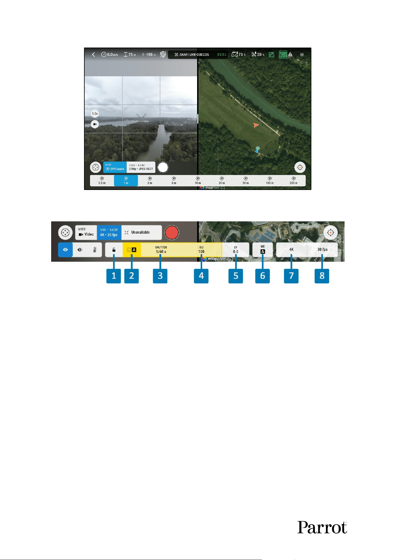
34
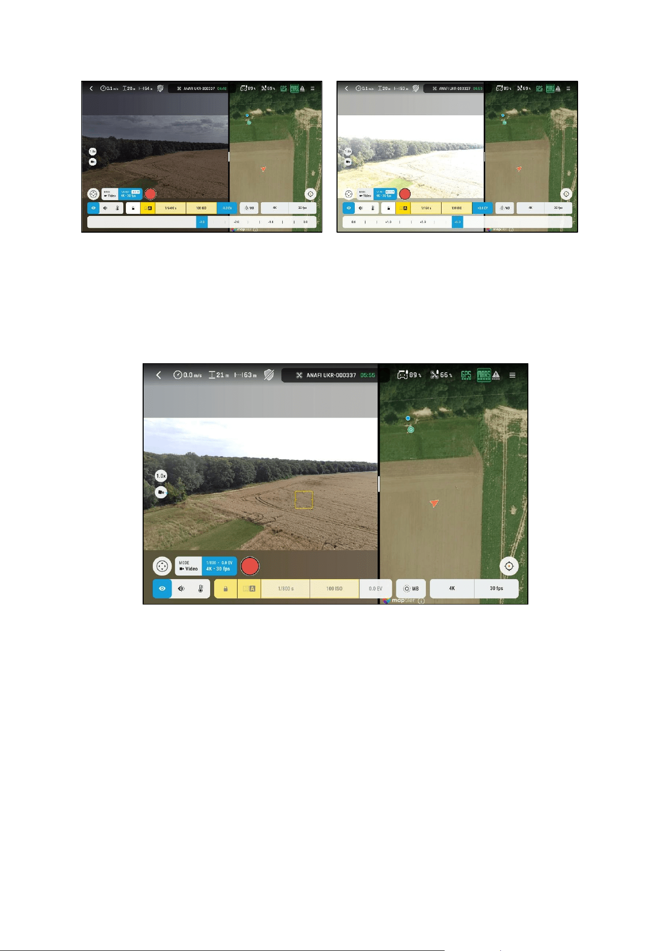
Figure 35: GPS lapse distance
11.4. Exposure adjustments
Figure 36: Automac exposure
1. Lock/Unlock exposure toggle
5. EV correction
2. Manual/Auto exposure toggle
6. White Balance
3. SHUTTER speed
7. Photo/Video resolution
4. ISO value
8. Video framerate
The user can control Image exposure manually or automacally.
11.4.1. Auto exposure mode
Auto exposure mode is acvated by default.
In Auto exposure mode, Shuer speed and ISO parameters are adjusted automacally depending on
the scene. You can congure manually Shuer speed or ISO parameters, and the other one will be
adjusted automacally to keep correct exposure in the whole scene.
In Auto exposure mode, you can congure EV correcon from -3.0EV to +3.0EV by using the EV slider
or the + and – buons on the Skycontroller.
S K Y C O N T R O L L E R UKR
35
© 2026 Parrot Drones SAS. All Rights Reserved.
Figure 37: Imaging - Exposure correcon -3EV to +3EV
In Auto exposure mode, there are two methods to lock the exposure:
o Tap the Lock on the le-hand side of the screen to lock the exposure parameters to
their current value
o A long-press gesture anywhere in the streaming view to adjust and lock the exposure
parameters for that parcular region of interest in the scene:
Figure 38: Exposure lock by a long touch on a Region of Interest (ROI) in the streaming view
When the exposure is locked, a message displays in the HUD:
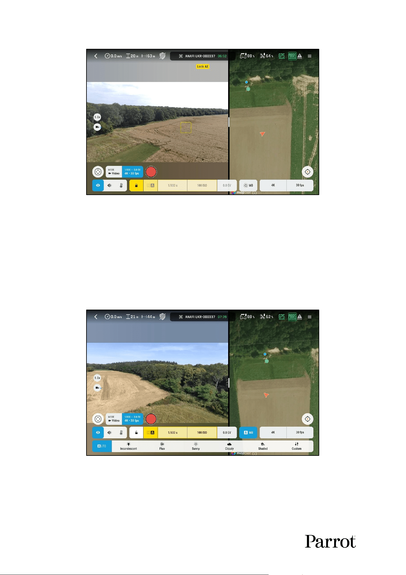
36
Figure 39: Lock AE message in the HUD
11.4.2. Manual exposure mode
Tap the Manual/Auto selector buon to switch to Manual exposure mode.
In Manual exposure mode there is no automac control of the exposure and therefore the image
might be over-exposed or under-exposed. Exposure lock is not available in Manual mode.
In Manual exposure mode, you congure both shuer speed and ISO value manually
11.5. White balance
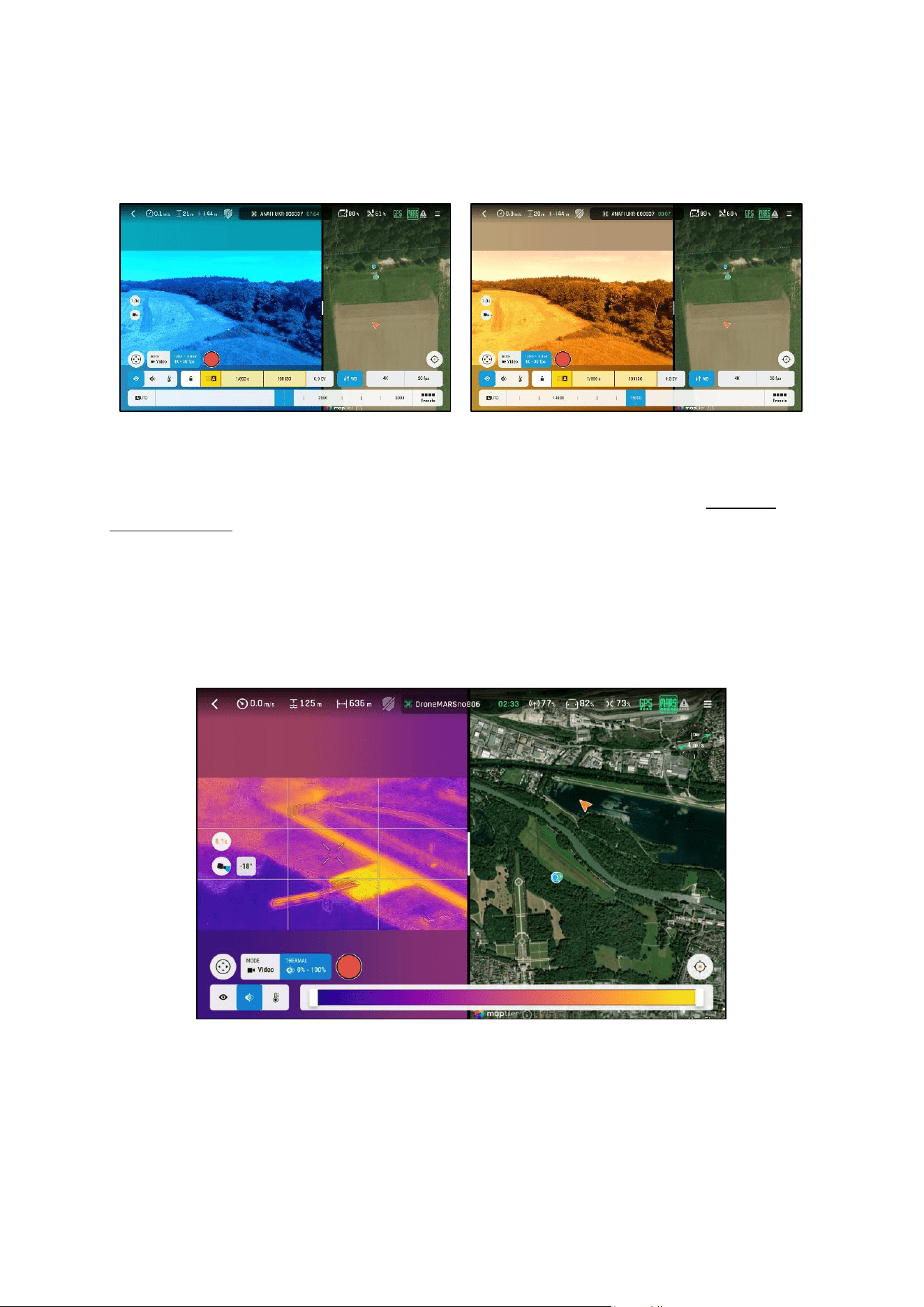
You can control White Balance automacally or manually:
Figure 40: White balance automac mode
5 predened modes are available:
o Incandescent
o Fluo
o Sunny
S K Y C O N T R O L L E R UKR
37
© 2026 Parrot Drones SAS. All Rights Reserved.
o Cloudy
o Shaded
In Custom mode you can directly select the color temperature:
Figure 41: Manual white balance adjustment
11.6. Thermal camera
Acvate Thermal mode through a dedicated buon on the Skycontroller UKR, refer to chapter 8.
Skycontroller UKR for more informaon.
Alternavely, acvate the Thermal camera via Imaging boom bar, and choose between Visible
mode, Thermal blending mode, and Thermal only mode.
11.6.1. Blending mode
In blending mode the raw thermal image is colorized with the plasma colormap and blended with
visible image:
Figure 42: Thermal blending mode
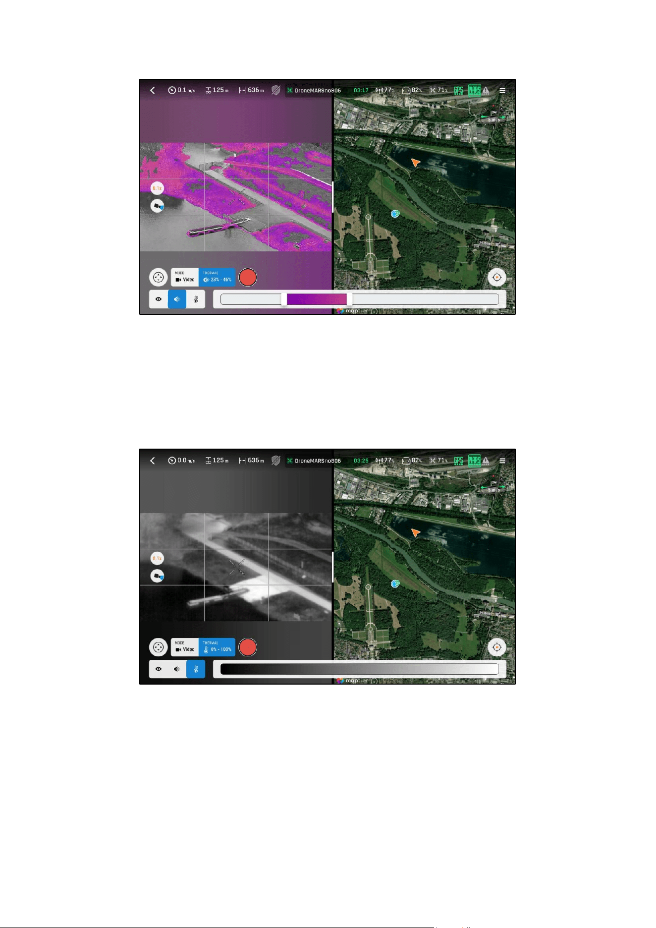
In thermal blending mode, you can adjust the colorizaon range so that only a poron of the scene is
colorized. Either the lowest temperature, highest temperature, or a middle range temperature can be
colorized.
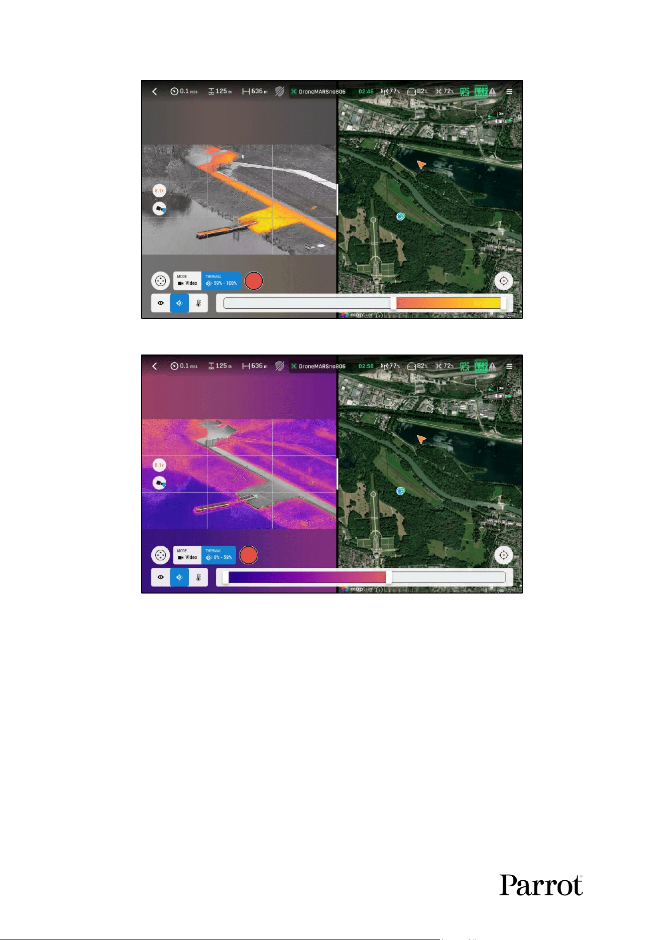
38
Figure 43: Thermal blending mode, highest temperature
Figure 44: Thermal blending, lowest temperature
S K Y C O N T R O L L E R UKR
39
© 2026 Parrot Drones SAS. All Rights Reserved.
Figure 45: Thermal blending mode, middle range temperature
You can adjust the colorizaon range either by grabbing the cursors in the FreeFlight 8 user interface,
or by using the + and – buons on the Skycontroller.
11.6.2. Thermal only mode
The user can also congure Thermal only mode. In thermal only mode there is no blending of visible
image with thermal image. Only the thermal image is displayed:
Figure 46: Thermal only mode
In thermal only mode the white hot color palee is used.
11.6.3. Thermal photo
Each me the aircra takes a thermal picture, it creates three les:
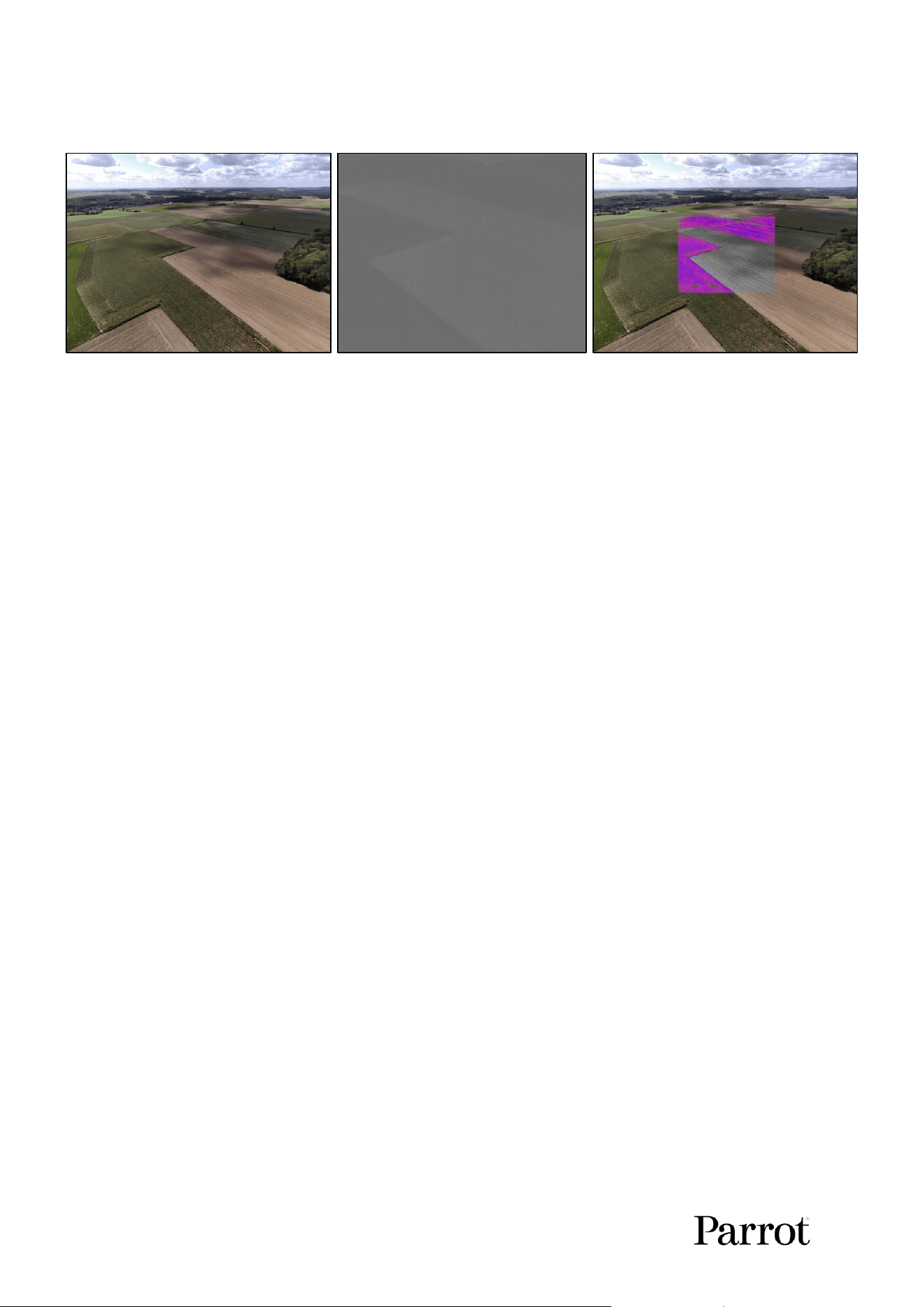
40
JPG – Visible Image
PNG – Raw Thermal Image
JPG – Blended Thermal + Visible
Image
1. JPG – Visible Image
• A full visible-light image with complete metadata.
2. PNG – Raw Thermal Image
• A raw 16-bit image from the thermal sensor.
• This image has low contrast because it is not normalized to 8-bit.
• Do not use this image directly. It must be processed separately, like a DNG raw image
in visible-light photography.
3. JPG – Blended Thermal + Visible Image
• A combined thermal and visible image, based on the selected blending seng.
• Includes complete metadata and addional thermal data.
• Recommended for thermal mapping and analysis.
S K Y C O N T R O L L E R UKR
41
© 2026 Parrot Drones SAS. All Rights Reserved.
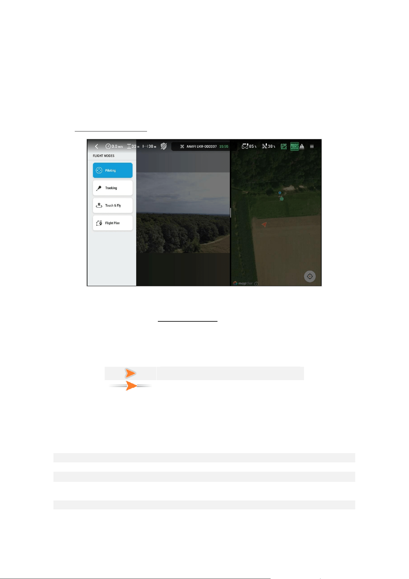
12. Flight modes
The Flight modes buon gives access to 4 dierent ying modes:
- Pilong: Manual pilong with joyscks.
- Tracking: Lock the gimbal onto a target.
- Touch & Fly: Fly the drone towards a way points set into the map view.
- Flight Plan: Autonomous ight through way points.
Refer to chapter 11. FreeFlight 8 for more informaon on how to change the ight mode.
Figure 47: Flight modes
12.1. Pilong
Manual ight mode as described in chapter 10. Pilong.
During ight, a visual indicator appears on the aircra icon when the Skycontroller UKR’s right joysck
is pushed forward, while the le joysck is in neutral posion (in joysck conguraon mode 2). This
icon conrms that the command sent to the drone is a pitch forward only command.
Regular aircra icon
Aircra during direct pitch forward ight
12.2. Tracking
Tracking mode allows the user to track a selected target, and to y the drone relave to that target,
keeping the target in the center of the frame. The following table briey describes the dierent
statuses and the corresponding drone behavior. Refer to the following chapter for more detail.
Rectangle color
Target status
Aircra behavior
Yellow
Automac target suggesons
Manual pilong
Blue
Manual target selecon
Manual pilong
Red
Manual target selecon is too
small
Manual pilong
Green
Target is dened and tracked
Pilong and gimbal relave to target
Orange
Target is lost and searched for
Pilong relave to the center of the
frame and gimbal is manually piloted
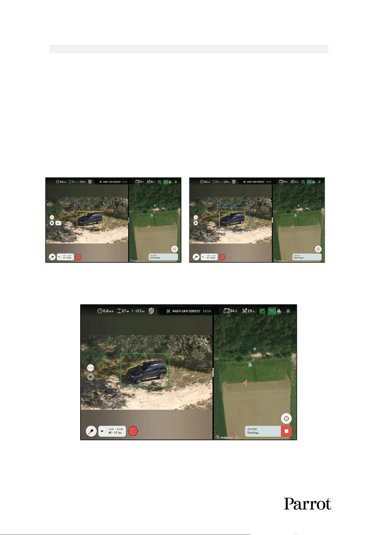
42
Purple
Tracking is paused
Manual pilong
12.2.1. Target selecon
A neural network searches for people and vehicles in the image.
Target suggesons appear within a yellow rectangle. Examples of tracking suggeson selected by the
arcial intelligence algorithm can include:
o People
o Vehicles (cars, motorbikes, boats)
o Animals
Tap a target in a yellow rectangle to select it.
Alternavely, manually select a target by drawing a rectangle in the image:
Figure 48: Tracking target suggestion
Figure 49: Manual selection of a target
12.2.2. Target tracking
A green rectangle in the image indicates that the target is being tracked:
Figure 50: Target tracking
The drone gimbal tracks the target.
S K Y C O N T R O L L E R UKR
43
© 2026 Parrot Drones SAS. All Rights Reserved.
The pilong of the drone is relave to the tracked target. The ight commands are relave to the
target. If the user moves forward and the target moves to the side the drone will make a curve.
If the drone loses the target, the rectangle turns orange. The algorithm searches for the target while
predicting its position for several seconds. It then focuses the search at the center of the frame. The
user can change the camera orientation, to facilitate the target redetection. For example, if the
target disappears behind a wall, the pilot can move the camera’s focus to the end of the wall and the
tracking restarts as soon as the target reappears.
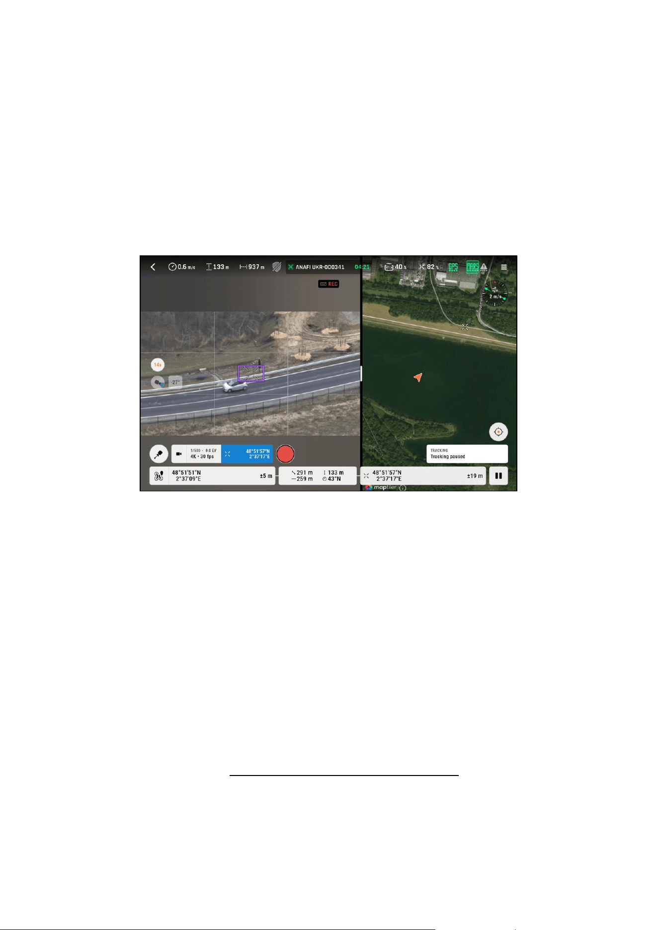
If a yaw or pitch piloting command is sent while a target is being tracked, then the tracking enters the
“Pause” mode. The rectangle around the target turns purple in color:
Figure 51: Tracking paused by pitch or yaw pilong command
The “Pause” mode is maintained as long as the yaw or pitch pilong command is received by the
drone. As soon as the pilong command stops, the drone enters the “Searching” mode and looks for
a target.
The “Pause” mode is designed to allow the pilot to assist the tracking algorithm. For instance, if the
tracker starts to follow another target than the expected one, the pilot can switch back to the
expected one using this Pause mode.
To end the target tracking, press the Stop button (white with red background). The target
suggestions reappear, and the drone returns to manual piloting behavior.
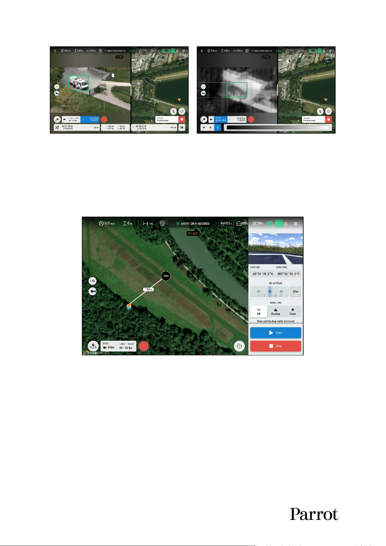
Tracking is compable with the Cursor on Target funcon.
o A recle points at the target in both the streaming view and the map view
o Target coordinates are displayed in the boom bar.
For more informaon, refer to chapter 13.14.1.5. Cursor on Target calibraon.
Tracking is compable with the thermal camera display. If the thermal mode is on, the target tracking
will use both visible and thermal data at the thermal image framerate.
44
Figure 52: Tracking and Cursor on Target
Figure 53: Tracking in thermal mode
NOTE: Any change on the thermal UI conguraon (through the slider for instance), has no eect on
the tracking algorithm performance.
12.3. Touch & Fly
Touch & Fly is a ying mode in which you can y the drone towards a waypoint.
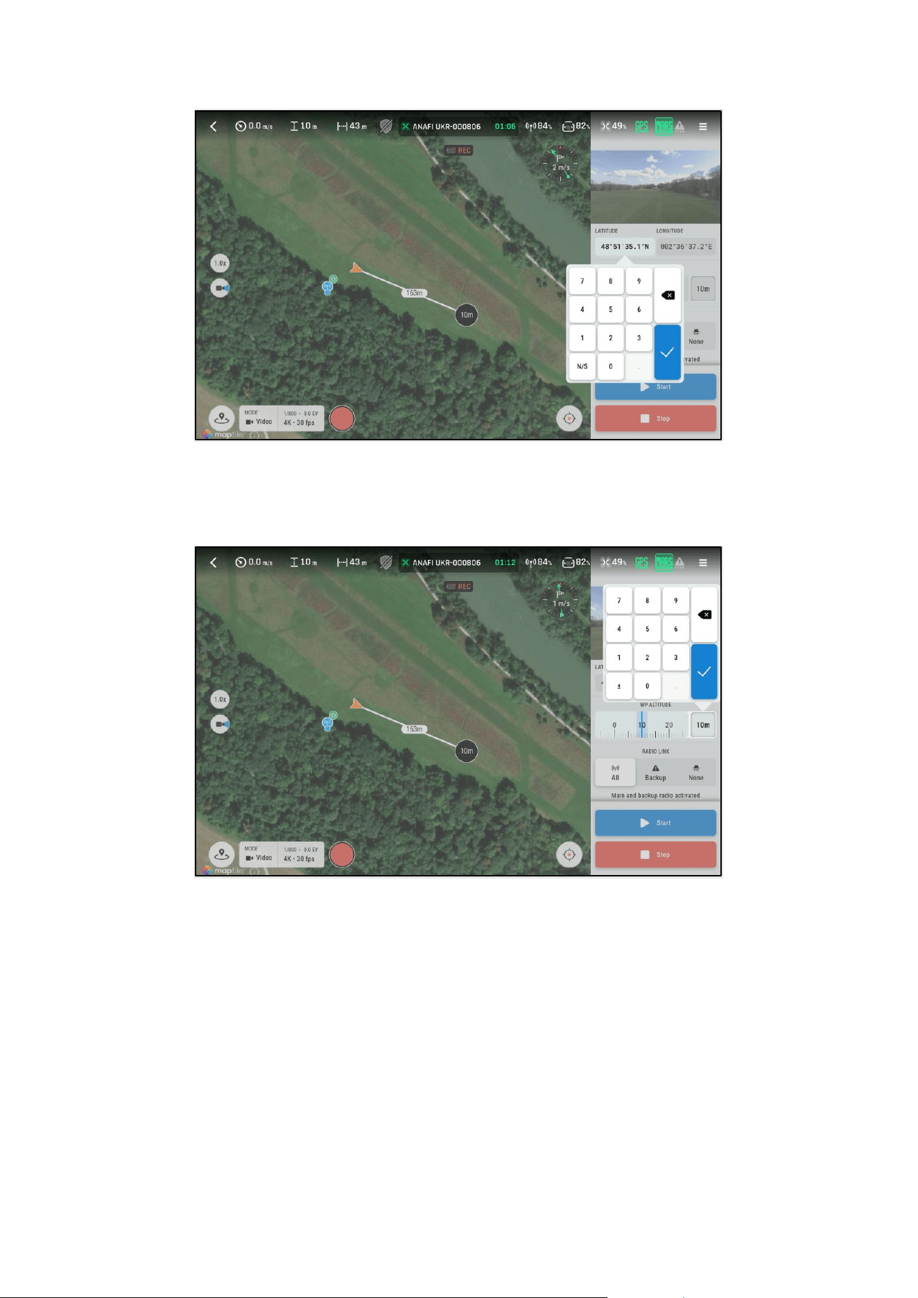
12.3.1. Fly to a waypoint
Figure 54: Set a waypoint in the map
Tap in the map view to set a waypoint (WP) at a given locaon.
The distance between the drone and the waypoint is indicated.
If the drone is ying the waypoint altude inializes at the drone’s current altude. If the drone is
grounded the waypoint altude inializes at 20 m.
You can modify the WP posion in the map view. You can also manually edit the WP coordinates
thanks to a virtual keyboard by clicking the coordinates in the right panel:
S K Y C O N T R O L L E R UKR
45
© 2026 Parrot Drones SAS. All Rights Reserved.
Figure 55: Manual edion of the WP coordinates
You can manually edit the waypoint altude (relave to the takeo point). Either move the altude
slider, or tap the buon on the right side to open a virtual keyboard:
Figure 56: Edit WP altude with the virtual keyboard
You can set the radio link used on the trajectory towards the waypoint.
Three opons are available for the radio link:
o All: The user receives the video feed during the ight.
o Backup: The user receives only basic telemetry.
o None: Radio silence mode, the drone does not transmit any radio signal.
Aer reaching the waypoint in Backup radio or silence mode the drone will restore the MARS radio
link.