
E-LPRC500 User Manual
Page | 1 Copyright©2025 ZKTECO. CO., LTD. All rights reserved.
User Manual
E-LPRC500
Date: August 2025
Doc Version: 1.0
English
Thank you for choosing our product. Please read the instructions carefully
before operation. Follow these instructions to ensure that the product is
functioning properly. The images shown in this manual are for illustrative
purposes only.
For further details, please visit our Company’s website
www.zkteco.com.

E-LPRC500 User Manual
Page | 1 Copyright©2025 ZKTECO. CO., LTD. All rights reserved.
Copyright © 2025 ZKTECO CO., LTD. All rights reserved.
Without the prior written consent of ZKTeco, no portion of this manual can be copied or forwarded in any
way or form. All parts of this manual belong to ZKTeco and its subsidiaries (hereinafter the "Company" or
"ZKTeco").
Trademark
is a registered trademark of ZKTeco. Other trademarks involved in this manual are owned by
their respective owners.
Disclaimer
This manual contains information on the operation and maintenance of the ZKTeco equipment. The
copyright in all the documents, drawings, etc. in relation to the ZKTeco supplied equipment vests in and is
the property of ZKTeco. The contents hereof should not be used or shared by the receiver with any third
party without express written permission of ZKTeco.
The contents of this manual must be read as a whole before starting the operation and maintenance of the
supplied equipment. If any of the content(s) of the manual seems unclear or incomplete, please contact
ZKTeco before starting the operation and maintenance of the said equipment.
It is an essential pre-requisite for the satisfactory operation and maintenance that the operating and
maintenance personnel are fully familiar with the design and that the said personnel have received
thorough training in operating and maintaining the machine/unit/equipment. It is further essential for the
safe operation of the machine/unit/equipment that personnel have read, understood and followed the
safety instructions contained in the manual.
In case of any conflict between terms and conditions of this manual and the contract specifications,
drawings, instruction sheets or any other contract-related documents, the contract conditions/documents
shall prevail. The contract specific conditions/documents shall apply in priority.
ZKTeco offers no warranty, guarantee or representation regarding the completeness of any information
contained in this manual or any of the amendments made thereto. ZKTeco does not extend the warranty
of any kind, including, without limitation, any warranty of design, merchantability or fitness for a particular
purpose.
ZKTeco does not assume responsibility for any errors or omissions in the information or documents which
are referenced by or linked to this manual. The entire risk as to the results and performance obtained from
using the information is assumed by the user.
ZKTeco in no event shall be liable to the user or any third party for any incidental, consequential, indirect,
special, or exemplary damages, including, without limitation, loss of business, loss of profits, business
interruption, loss of business information or any pecuniary loss, arising out of, in connection with, or

E-LPRC500 User Manual
Page | 2 Copyright©2025 ZKTECO. CO., LTD. All rights reserved.
relating to the use of the information contained in or referenced by this manual, even if ZKTeco has, of the
possibility of such damages.
This manual and the information contained therein may include technical, other inaccuracies or
typographical errors. ZKTeco periodically changes the information herein which will be incorporated into
new additions/amendments to the manual. ZKTeco reserves the right to add, delete, amend or modify the
information contained in the manual from time to time in the form of circulars, letters, notes, etc. for better
operation and safety of the machine/unit/equipment. The said additions or amendments are meant for
improvement /better operations of the machine/unit/equipment and such amendments shall not give any
right to claim any compensation or damages under any circumstances.
ZKTeco shall in no way be responsible (i) in case the machine/unit/equipment malfunctions due to any
non-compliance of the instructions contained in this manual (ii) in case of operation of the
machine/unit/equipment beyond the rate limits (iii) in case of operation of the machine and equipment in
conditions different from the prescribed conditions of the manual.
The product will be updated from time to time without prior notice. The latest operation procedures and
relevant documents are available on http://www.zkteco.com
.
If there is any issue related to the product, please contact us.
ZKTeco Headquarters
Address ZKTeco Industrial Park, No. 32, Industrial Road,
Tangxia Town, Dongguan, China.
Phone +86 769 - 82109991
Fax +86 755 - 89602394
For business-related queries, please write to us at [email protected]m
.
To know more about our global branches, visit www.zkteco.com.

E-LPRC500 User Manual
Page | 3 Copyright©2025 ZKTECO. CO., LTD. All rights reserved.
About the Company
ZKTeco is one of the world’s largest manufacturer of RFID and Biometric (Fingerprint, Facial, Finger-vein)
readers. Product offerings include Access Control readers and panels, Near & Far-range Facial Recognition
Cameras, Elevator/floor access controllers, Turnstiles, License Plate Recognition (LPR) gate controllers and
Consumer products including battery-operated fingerprint and face-reader Door Locks. Our security
solutions are multi-lingual and localized in over 18 different languages. At the ZKTeco state-of-the-art
700,000 square foot ISO9001-certified manufacturing facility, we control manufacturing, product design,
component assembly, and logistics/shipping, all under one roof.
The founders of ZKTeco have been determined for independent research and development of biometric
verification procedures and the productization of biometric verification SDK, which was initially widely
applied in PC security and identity authentication fields. With the continuous enhancement of the
development and plenty of market applications, the team has gradually constructed an identity
authentication ecosystem and smart security ecosystem, which are based on biometric verification
techniques. With years of experience in the industrialization of biometric verifications, ZKTeco was
officially established in 2007 and now has been one of the globally leading enterprises in the biometric
verification industry owning various patents and being selected as the National High-tech Enterprise for 6
consecutive years. Its products are protected by intellectual property rights.
About the Manual
This manual introduces the operations of E-LPRC500.
All figures displayed are for illustration purposes only. Figures in this manual may not be exactly consistent
with the actual products.

E-LPRC500 User Manual
Page | 4 Copyright©2025 ZKTECO. CO., LTD. All rights reserved.
Document Conventions
Conventions used in this manual are listed below:
GUI Conventions
For Software
Convention Description
Bold font Used to identify software interface template names e.g. OK, Confirm, Cancel.
>
Multi-level menus are separated by these brackets. For example, File > Create >
Folder.
For Device
Convention Description
< >
Button or key names for devices. For example, press <OK>.
[ ]
Window names, menu items, data table, and field names are inside square
brackets. For example, pop up the [New User] window.
/
Multi-level menus are separated by forwarding slashes. For example,
File/Create/Folder.
Symbols
Convention Description
This represents a note that needs to pay more attention to.
The general information which helps in performing the operations faster.
The information which is significant.
Care taken to avoid danger or mistakes.
The statement or event that warns of something or that serves as a cautionary
example.

E-LPRC500 User Manual
Page | 5 Copyright©2025 ZKTECO. CO., LTD. All rights reserved.
Table of Contents
SAFETY PRECAUTIONS ............................................................................................................................... 6
1 OVERVIEW ............................................................................................................................................ 7
1.1 Features ................................................................................................................................................. 7
1.2 Appearance .......................................................................................................................................... 8
1.3 Port Definition ...................................................................................................................................... 8
2 SYSTEM CONFIGURATION ................................................................................................................ 10
2.1 Software Environment ...................................................................................................................... 10
2.2 Network and IP Address Configuration ......................................................................................... 10
2.2.1 Default Parameter Settings .................................................................................................................................................. 10
2.2.2 Connectivity Test ........................................................................................................................................................................ 10
3 CAMERA ACCESS OVER A WEB BROWSER ........................................................................................ 12
3.1 Login .................................................................................................................................................... 12
3.2 Video .................................................................................................................................................... 13
3.3 Options ................................................................................................................................................ 16
3.3.1 Recognition.................................................................................................................................................................................... 16
3.3.2 AV Settings ..................................................................................................................................................................................... 18
3.3.3 Basic Network ............................................................................................................................................................................... 21
3.3.4 Allow List ......................................................................................................................................................................................... 26
3.3.5 Advanced Network ................................................................................................................................................................... 27
3.3.6 Peripherals ...................................................................................................................................................................................... 31
3.4 Query Data .......................................................................................................................................... 35
3.4.1 Picture ............................................................................................................................................................................................... 35
3.4.2 Replay ................................................................................................................................................................................................ 36
3.5 System ................................................................................................................................................. 37
3.5.1 Device Information.................................................................................................................................................................... 37
3.5.2 User Management ..................................................................................................................................................................... 38
3.5.3 Time Settings ................................................................................................................................................................................ 38
3.5.4 Storage Management ............................................................................................................................................................. 39
3.5.5 Log Detect ...................................................................................................................................................................................... 41
3.5.6 Configuration ................................................................................................................................................................................ 41
3.5.7 Theme Settings............................................................................................................................................................................ 42
3.5.8 System Maintenance................................................................................................................................................................ 43
Q&A ............................................................................................................................................................ 44

E-LPRC500 User Manual
Page | 6 Copyright©2025 ZKTECO. CO., LTD. All rights reserved.
Safety Precautions
Electrical safety
Complete the grounding properly and set up surge protection before connecting an external cable
to the device; otherwise, static electricity can damage the Mainboard.
Make sure to use the standard voltage applicable in your country or region (the rated voltage of
the device is 220V). Power mismatch may cause a short circuit or damage the device.
Operational safety
Transportation and other issues may damage the device’s hardware. Check if the device has
significant damage before installation. If the device has major defects, contact your dealer as soon
as possible.
Do not connect or disconnect cables to/from the device when it is working.
Do not keep the device in an unstable place. Handle the device with care. Do not place heavy
objects on top of the device.
Do not use rosin, alcohol, benzene, pesticides, and other volatile substances to clean the device,
because they may damage the device enclosure. Clean the enclosure with a piece of soft cloth or a
small amount of cleaning agent.
Unauthorized persons are not allowed to open the unit. For any queries regarding the usage of the
product, contact an authorized technician.

E-LPRC500 User Manual
Page | 7 Copyright©2025 ZKTECO. CO., LTD. All rights reserved.
1 Overview
The E-LPRC500 camera is designed to meet the needs of traffic management, law enforcement, security,
parking, tolling, and Intelligent Transport Systems (ITS).
With advanced algorithms, high-resolution imaging, and robust adaptability, the E-LPRC500 delivers
unparalleled performance in vehicle and license plate recognition.
It is an intelligent imaging device with integrated front-end capture and recognition specifically
designed for mid-to-high-end parking entrance and exit scenarios. To deal with "unattended" and
"contactless payment" in the scenario, this series not only provides 5MP HD imaging solution with
exceptional adaptability to challenging lighting conditions, diverse license plate/vehicle information
recognition, surveillance video recording, intelligent light compensation, and front-end storage, but
also supports features such as trigger for unlicensed vehicles, license plate anti-counterfeiting, and
offline ad hoc networking. It can recognize events such as vehicle detention, vehicle return, and vehicle
following, and greatly reducing after-sales maintenance costs.
1.1 Features
5MP HD Camera
Advanced license plate/vehicle recognition algorithm
High-precision vehicle and license plate recognition algorithm
7 types of vehicle identification, and more than 2100 specific vehicle types
To prevent misidentification and filter out fake license plates
Vehicle event recognition: vehicle retention, returns, and tailgating, enhancing operational
efficiency and security.
Web-configurable global license plate recognition algorithm
Peripheral device linkage management at entrances and exits
One-click binding of primary and secondary devices
Easy connection
Offline identification
All-round development connection support, easy for users to develop secondary functions
E-LPRC500 User Manual
Page | 8 Copyright©2025 ZKTECO. CO., LTD. All rights reserved.
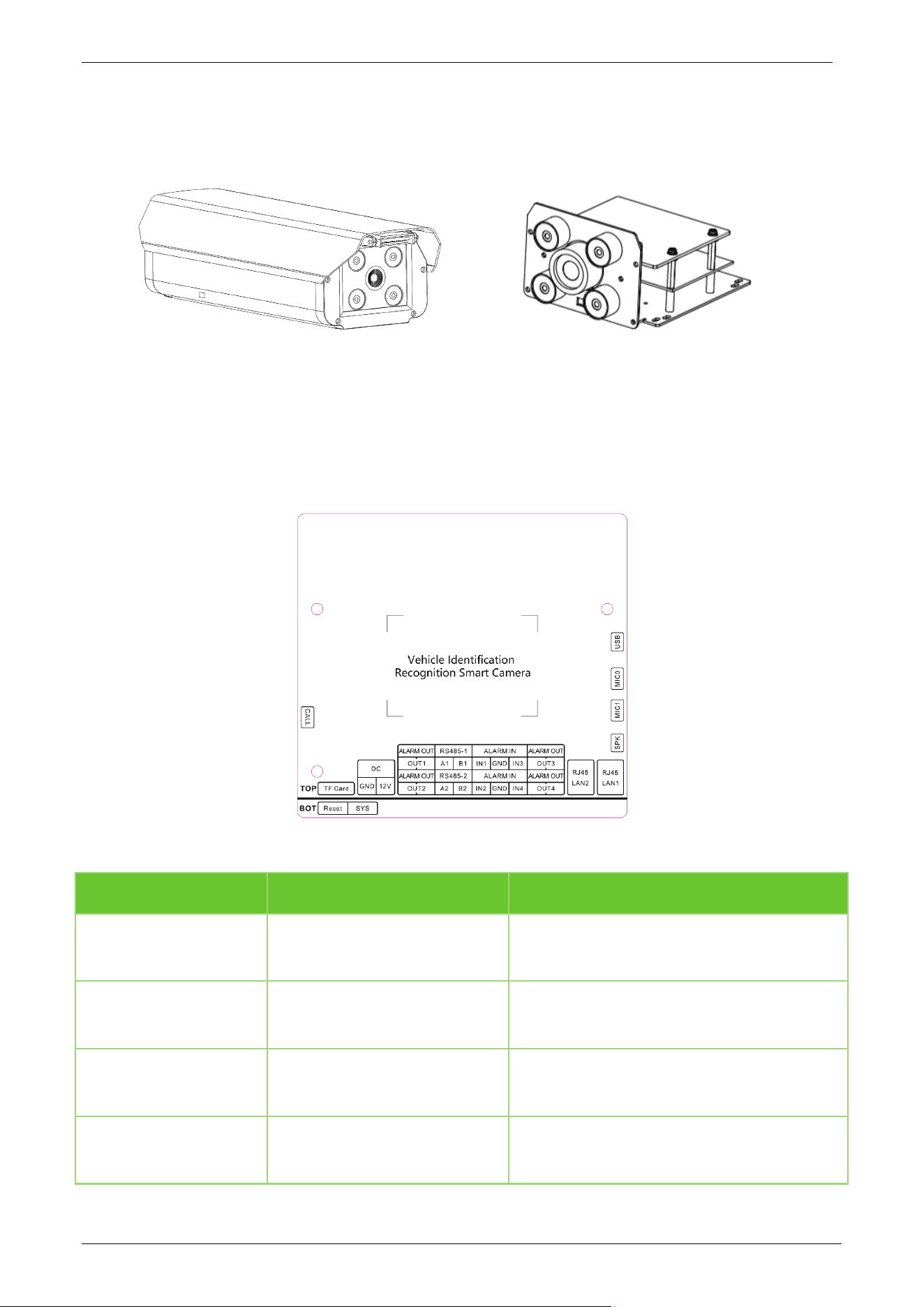
1.2 Appearance
Standard Set Module Set
1.3 Port Definition
Wiring Diagram
Port Description
Function Pin Description
Power(DC)
GND/12V
Support 9-15V DC, recommended 12V/2A
If connect an external speaker, please use
12V 3A Power.
Network
LAN1/LAN2
1 x 10/100/1000Mbps adaptive RJ45
port(LAN1)
1 x 10/100Mbps adaptive RJ45port(LAN2)
IO Output
(ALARM OUT)
OUT1/OUT2/OUT3/OUT4/GND Can be used for raising the barrier gate lever
IO Input
(ALARM IN)
IN1/IN2/IN3/IN4/GND
Groundable inductive coil for external signal
triggering capture

E-LPRC500 User Manual
Page | 9 Copyright©2025 ZKTECO. CO., LTD. All rights reserved.
Serial(RS485-1)
A1/B1
Connect to the host computer and output
the recognition result
Serial(RS485-2)
A2/B2
Connect to the host computer and output
the recognition result
TF Card
TF-Card TF-Card, support max to 256GB
System Light
SYS
It will long light when the power on
beginning, and will flash when the device
runtime normally
Reset Button
Reset
Long press the button 5~10sec when the
power on, then the device will recovery to
the factory
CALL
CALL Trigger the voice call
Speaker
SPK
Speaker output, output power max to 4Ω
12W
Mic 0
MIC0 Input for microphone
Mic 1
MIC1 Input for microphone
USB
USB Connect external module

E-LPRC500 User Manual
Page | 10 Copyright©2025 ZKTECO. CO., LTD. All rights reserved.
2 System Configuration
2.1 Software Environment
CPU: Intel Dual-core CPU A7@900MHz 0.5 TOPS
RAM: 1GB or above
Network Port: 100M Ethernet port
Operating System: 32-bit or 64-bit operating system, such as Windows 7, Windows 8, Windows 10
Internet Explorer: Microsoft Internet Explorer 11.0 or later, Microsoft Edge, Google Chrome and
Firefox.
2.2 Network and IP Address Configuration
Set the IP address of the camera such that it remains in the same network segment as the PC.
Note: In the same LAN environment, the IP address cannot be the same. Otherwise, IP address conflict
can lead to device malfunction.
2.2.1 Default Parameter Settings
Before using the camera, set the IP address, Gateway address, and other information of the camera
without any fault. The user can modify the default parameter settings according to requirements.
LAN1: LAN2:
IP Address: 192.168.1.100 IP Address: 10.10.1.100
Subnet Mask: 255.255.255.0 Subnet Mask: 255.255.128.0
Gateway: 192.168.1.1 Gateway: 10.10.1.1
Under normal circumstances, please prioritize using the LAN1 network port.
2.2.2 Connectivity Test
Open the Start menu on the PC and type cmd in the search box once the camera IP Address is set. In
the command prompt window, type ping and the camera IP Address (e.g., Ping 192.168.0.18) to test the
connectivity between the PC and camera.
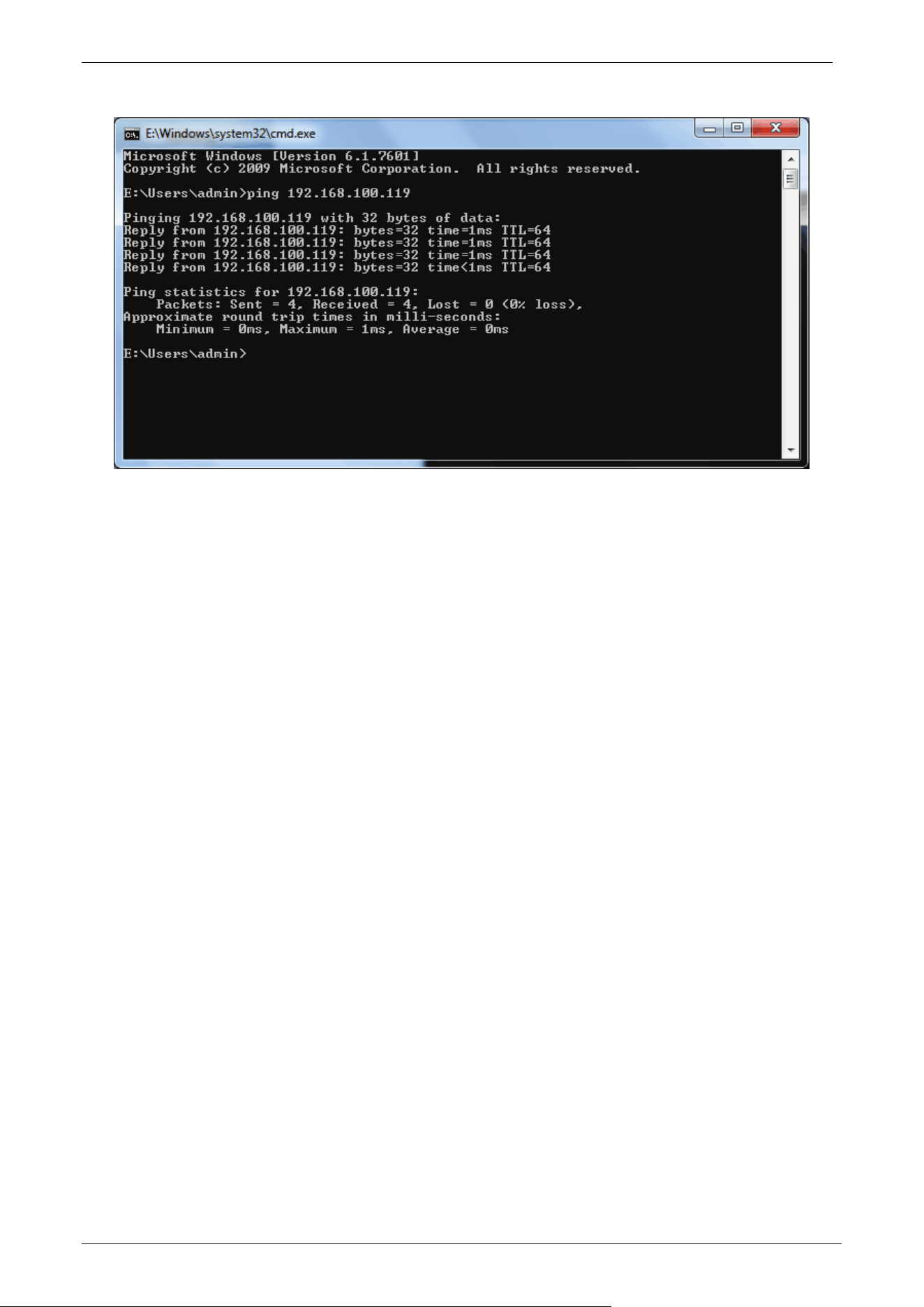
E-LPRC500 User Manual
Page | 11 Copyright©2025 ZKTECO. CO., LTD. All rights reserved.
If the message is "Request timed out" or "Destination host unreachable", it means the PC and the
camera are not connected properly. Perform the following steps:
Check whether the hardware connection is correct.
Check whether the TCP/IP Addresses of the PC and the camera are in the same network segment.
Check whether the ping command is disabled.

E-LPRC500 User Manual
Page | 12 Copyright©2025 ZKTECO. CO., LTD. All rights reserved.
3 Camera Access over a Web Browser
3.1 Login
1. Type the IP Address (default: 192.168.1.100) of the camera in the address bar of a web browser.
Then enter the name (default: admin) and password (default: admin) and click [Login], as
displayed in the below figure.
Note: If the user is accessing the camera by IE browser for the first time, the user needs to install the
control. If the user logins with other browsers, the user doesn’t need to install the control.
2. After login successfully, the user can preview the video, as displayed in the figure below:
E-LPRC500 User Manual
Page | 13 Copyright©2025 ZKTECO. CO., LTD. All rights reserved.
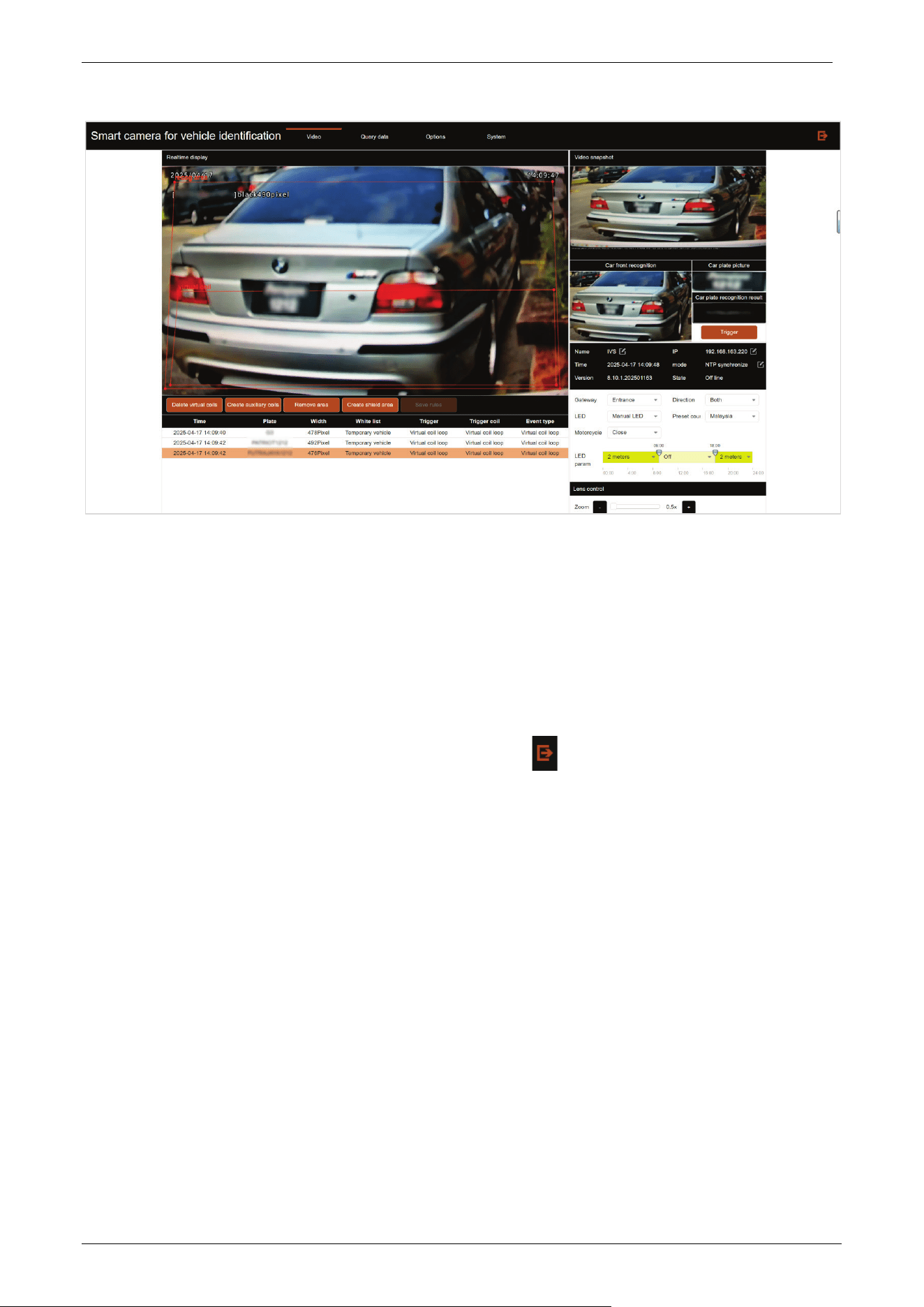
3.2 Video
Click [Video] to access the video preview page. The user can see the output screen and auxiliary
wireframe of the camera on the following interface. When the license plate appears on the screen, the
license plate number information recognized by the system will be displayed on the right side of the
screen, and the snapshot history will be recorded below. At the same time, the system provides basic
settings at the bottom right of the main interface. Click the button in the upper right corner of the
interface to log out of the system.
E-LPRC500 User Manual
Page | 14 Copyright©2025 ZKTECO. CO., LTD. All rights reserved.
Full Screen: Double-click the video real-time display interface to display the video image in full
screen.
Adjustment of virtual coil and recognition area: The user can use the mouse to drag the vertices
on the wireframe to adjust the recognition area/virtual coil, or double-click the mouse on the
wireframe of the recognition area to create a new marker for adjustment. When the wireframe
adjustment is complete, you can click the Save rules button on the lower left to save the
wireframe. At the same time, there are Delete virtual coils and Remove area buttons on the lower
left side of the real-time display interface, which can delete the virtual coil / recognition area in the
real-time screen, and can also create the corresponding wireframe when the virtual coil/
recognition area does not exist in the real-time screen (default state).
Create auxiliary coils: The function is the same as that of a virtual coil.
Create shield area: When a shield area is set, license plate recognition will not be triggered when
the vehicle is in that area.
Trigger: Click the button on the right side of the page to manually capture an image. It will
automatically display the car front, car plate picture and car plate recognition result in the captured
image on the right.
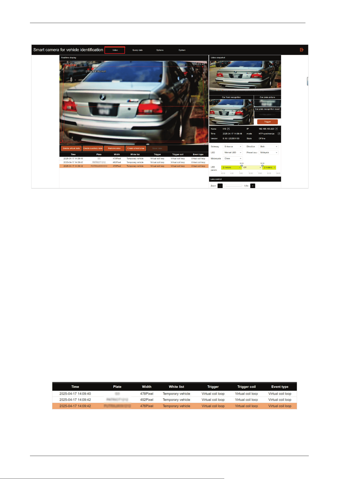
Snapshot history: There is a snapshot history record at the bottom of the real-time display
interface. It includes recognition time, license plate number, license plate width, allow list, trigger
type, trigger coil and event type.
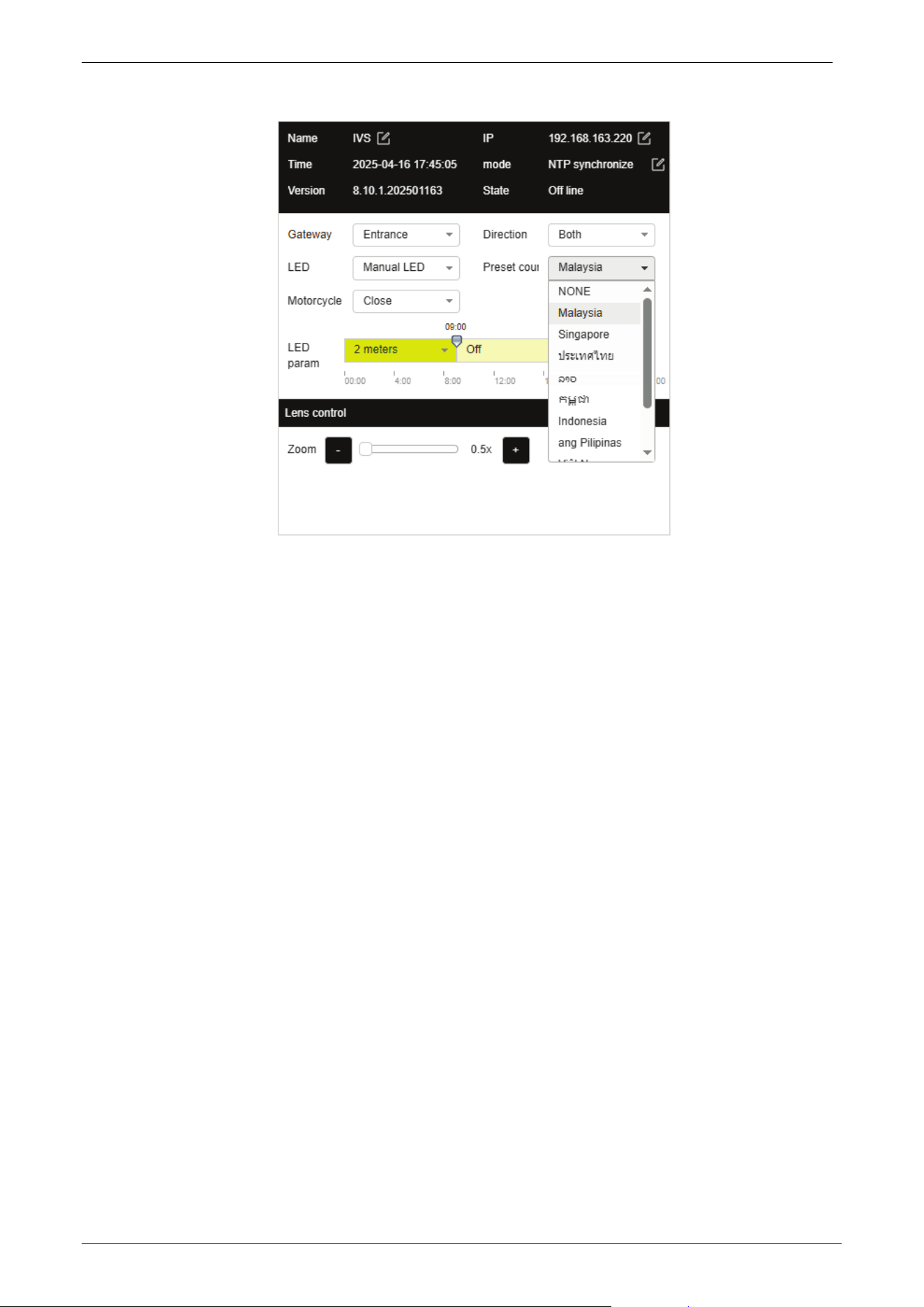
Basic Settings: There is a basic setting interface at the bottom right of the real-time display
interface, as shown in the following figure.
E-LPRC500 User Manual
Page | 15 Copyright©2025 ZKTECO. CO., LTD. All rights reserved.
o Name: Click the edit button to change the camera name.
o IP: Set the camera IP accordingly.
o NTP synchronize mode: Click the edit button to jump to the time configuration page.
o Gateway: Set the current installation position of the camera, Entrance or Exit.
o Direction: Set the traffic direction of the camera installation lane.
Up to down: It means that the license plate is recognized when the car approaches the
camera.
Down to up: It means that the license plate is recognized when the car drives away from
the camera.
Both: It means that the license plate is recognized regardless of whether the car
approaches or drives away from the camera.
o LED: Set the working status of the camera's fill light.
Manual LED: Turn on or off according to the set time.
Smart LED: isp algorithm automatically detects the environmental light source, turn on or
off.
Close LED: Turn off the fill light panel.
o Preset country: Set the corresponding country algorithm as needed, and the camera will
support recognizing license plates from whichever country is selected.
o Motorcycle: Open or close the function of recognizing motorcycles. Currently only
supports Indonesia.
o LED param: Set the time period for the camera to turn on fill light.
o Lens control: Zoom in and out of the display interface.
E-LPRC500 User Manual
Page | 16 Copyright©2025 ZKTECO. CO., LTD. All rights reserved.
3.3 Options
Click [Options] to enter the advanced settings interface, as shown below:
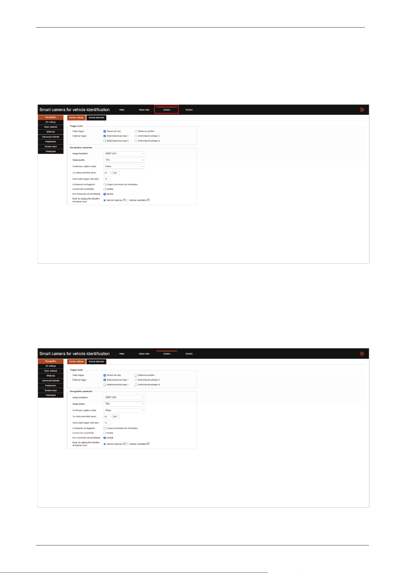
3.3.1 Recognition
Click the Recognition tab to enter the recognition settings interface.
Identity settings:
E-LPRC500 User Manual
Page | 17 Copyright©2025 ZKTECO. CO., LTD. All rights reserved.
Trigger mode: The type of trigger recognition can be checked.
Video trigger: Virtual coil loop: The recognition result is triggered when the license plate touches
the virtual coil; Stable recognition: The car stays within the virtual coil and outputs the recognition
results at regular intervals. The interval output duration is configured based on the “Same plate
trigger interval”. Don't check if it is not necessary.
External trigger: The camera has hardware interfaces for alarm in 1 or alarm in 2 to connect to
external signals. When an external signal is received, it can immediately trigger license plate
recognition; Ground sensing coils need to be laid during construction. Vehicles passing over the
ground sensing coils will trigger signals to be transmitted to the camera input port, triggering the
system to perform capture operations.
Recognition parameter: The image quality, image resolution, continuous capture mode, same
plate trigger interval, car plate pixel limit, unlicensed car triggered, license anti-counterfeit, non
motorized vehicle filtering, basis for judging the direction of vehicle travel can be set, and assist the
system to accurately identify vehicle information.
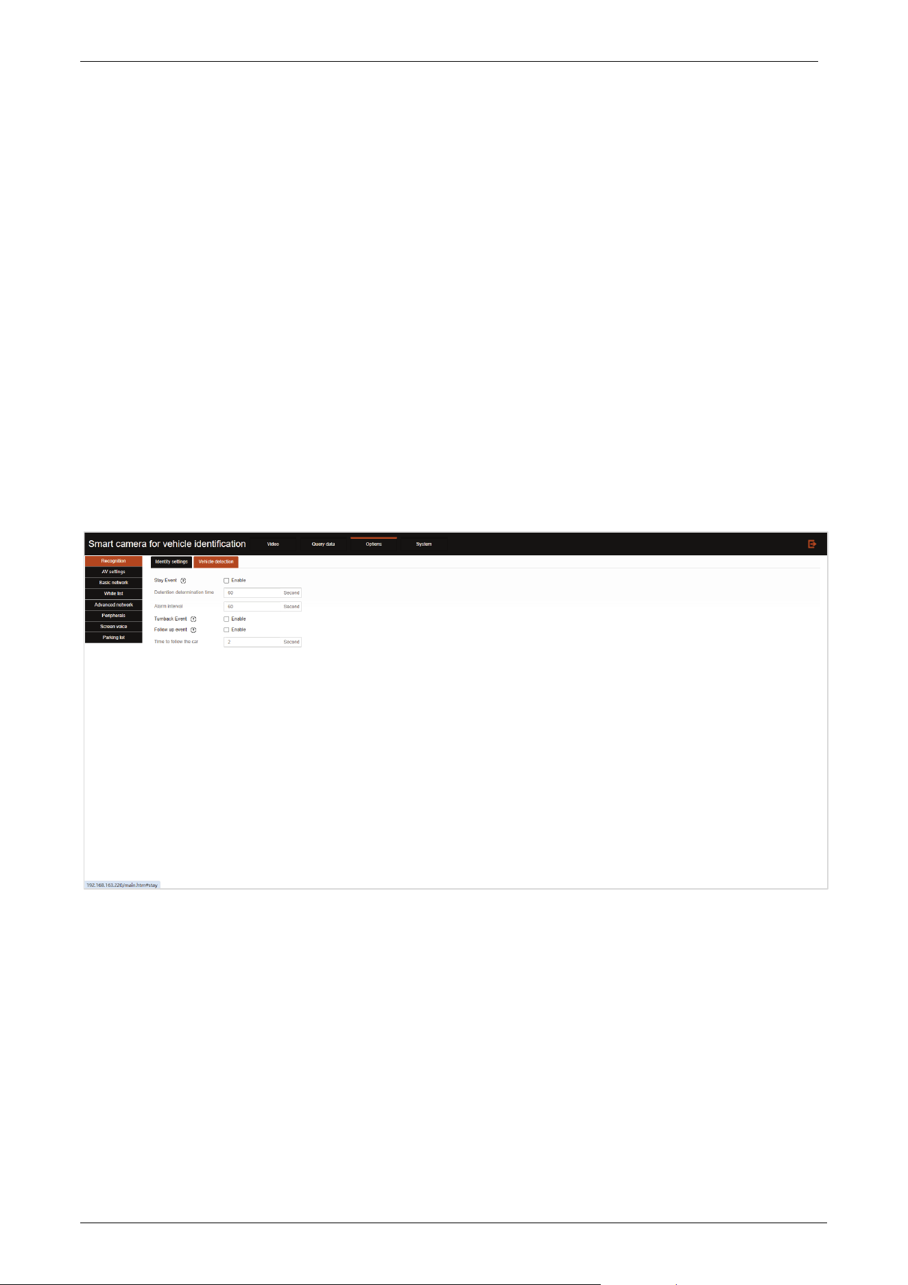
Vehicle detection:
Stay Event: After enabled, when the car stays in the camera recognition area for a period of time,
the camera will trigger a dwell time warning.
Detention determination time: It refers to how long the vehicle stays before triggering a warning.
Alarm interval: It refers how often do warnings occur.
Turnback Event: Refers to a situation where a vehicle that has passed through a virtual coil but has
not left the virtual coil will be identified as a turn back.
Follow up event: Determine whether the rear vehicle follows the front vehicle into the area.
Time to follow the car: Time determined to be a follow up event.
E-LPRC500 User Manual
Page | 18 Copyright©2025 ZKTECO. CO., LTD. All rights reserved.
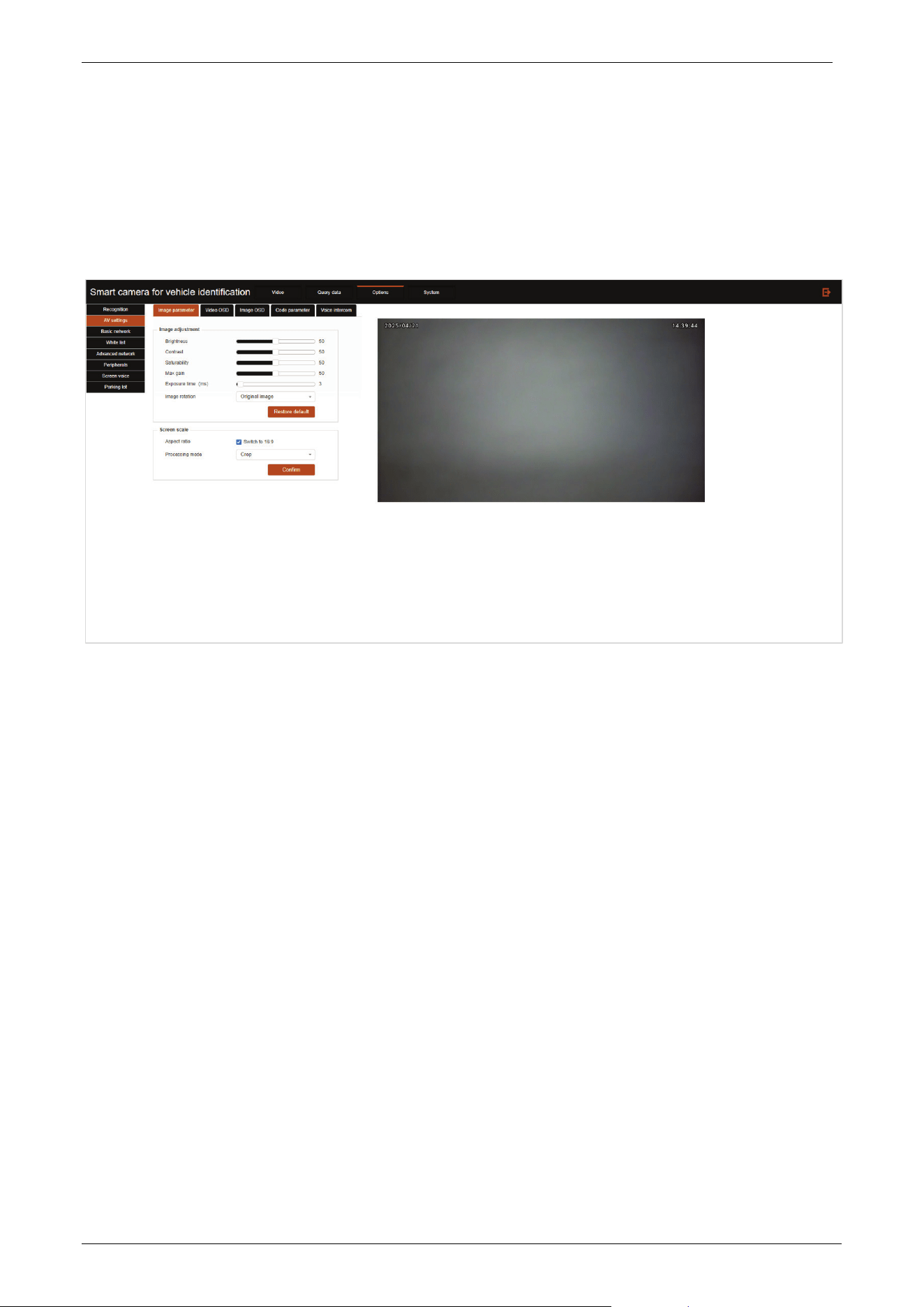
3.3.2 AV Settings
Click the AV settings tab to enter the AV Settings page.
Image parameter
Image parameter settings can be displayed in real time on the right side of the setup interface for
easy adjustment of contrast.
Brightness: Dragging the brightness progress bar can configure the brightness of the image.
Contrast: Drag the contrast progress bar to configure the contrast of the image.
Saturability: Drag the Saturation progress bar to configure the color saturation of the image,
when the value is configured to 0, the image is configured as a black and white image.
Max gain: Drag the Maximum Gain progress bar to configure the maximum gain value for the
camera to automatically adjust the exposure parameters. The user decides the value of the
maximum gain according to the actual application scenario.
Exposure time: In ms, the exposure time is the opening time of the electronic shutter of the CMOS
image sensor. Different exposure time can be configured according to different application
scenarios. The time set here is the maximum exposure time, and the camera will automatically
adjust the exposure time according to the brightness of the scene.
Image rotation: Users can choose the flip angle of the image according to the direction of the
actual installation of the camera.
Click the Restore default button to set all image parameters to default parameters.
Aspect ratio: The normal real-time display interface ratio is 4:3, which can be set to 16:9 through
the Screen scale.
Processing mode: Can be selected as Crop or Fill Border.
E-LPRC500 User Manual
Page | 19 Copyright©2025 ZKTECO. CO., LTD. All rights reserved.
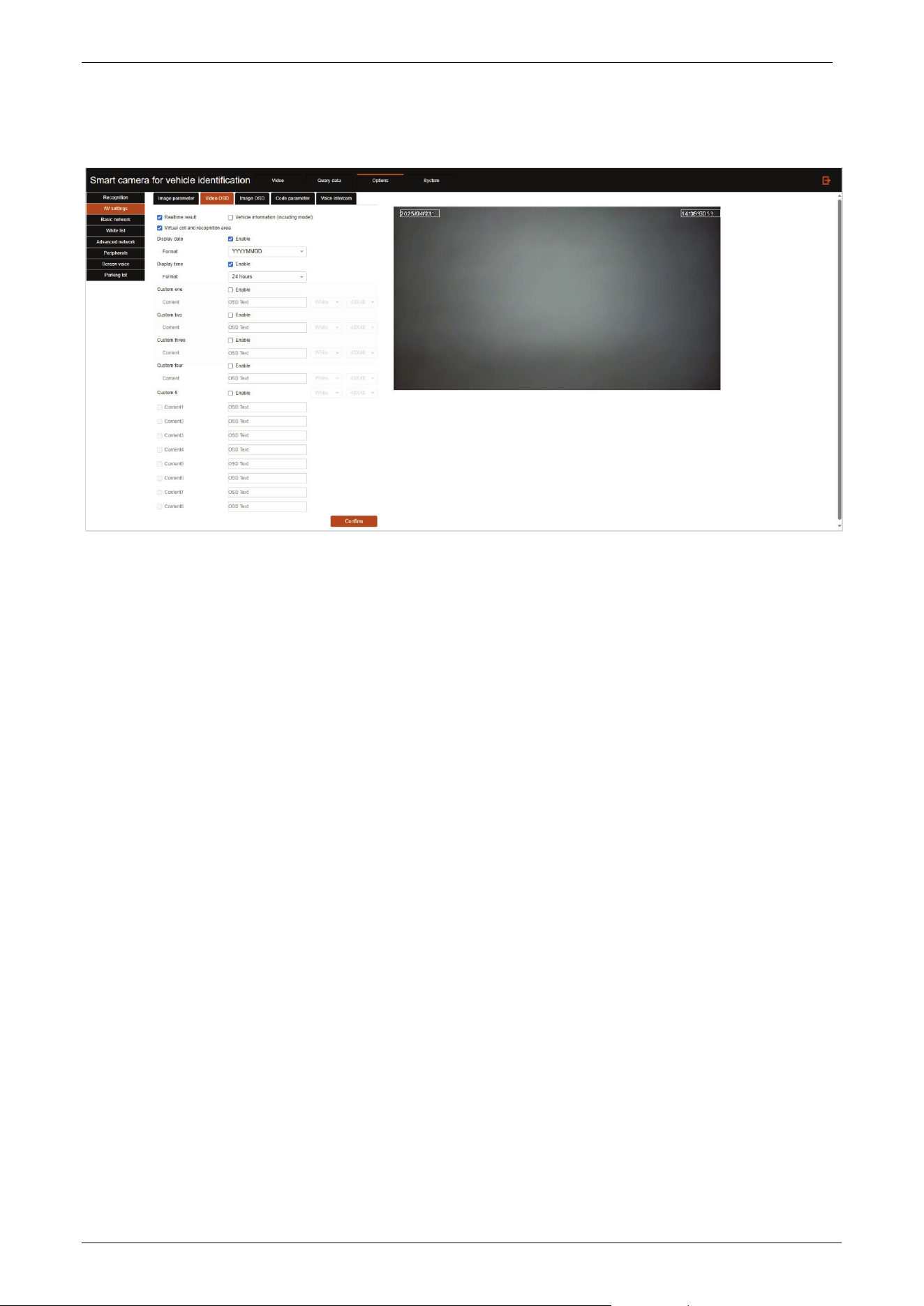
Video OSD
Realtime result: Display the real-time license plate recognition result as text on the top left of the
real-time screen.
Vehicle information: Display the real-time recognized license plate and other information on the
top left of the real-time screen.
Virtual coil and recognition area: Enable/disable the virtual coil and recognition area.
Display date: When enabled, you can configure the date format, and you can drag the text to
change the position in the real-time screen.
Display time: You can configure the time format after enabling, and you can drag the text to
change the position in the real-time screen.
Custom one/two/three/four/5: If enabled, you can configure the text content, support multiple
customized text configurations, in the real-time screen, you can drag the text to change the
position.
E-LPRC500 User Manual
Page | 20 Copyright©2025 ZKTECO. CO., LTD. All rights reserved.
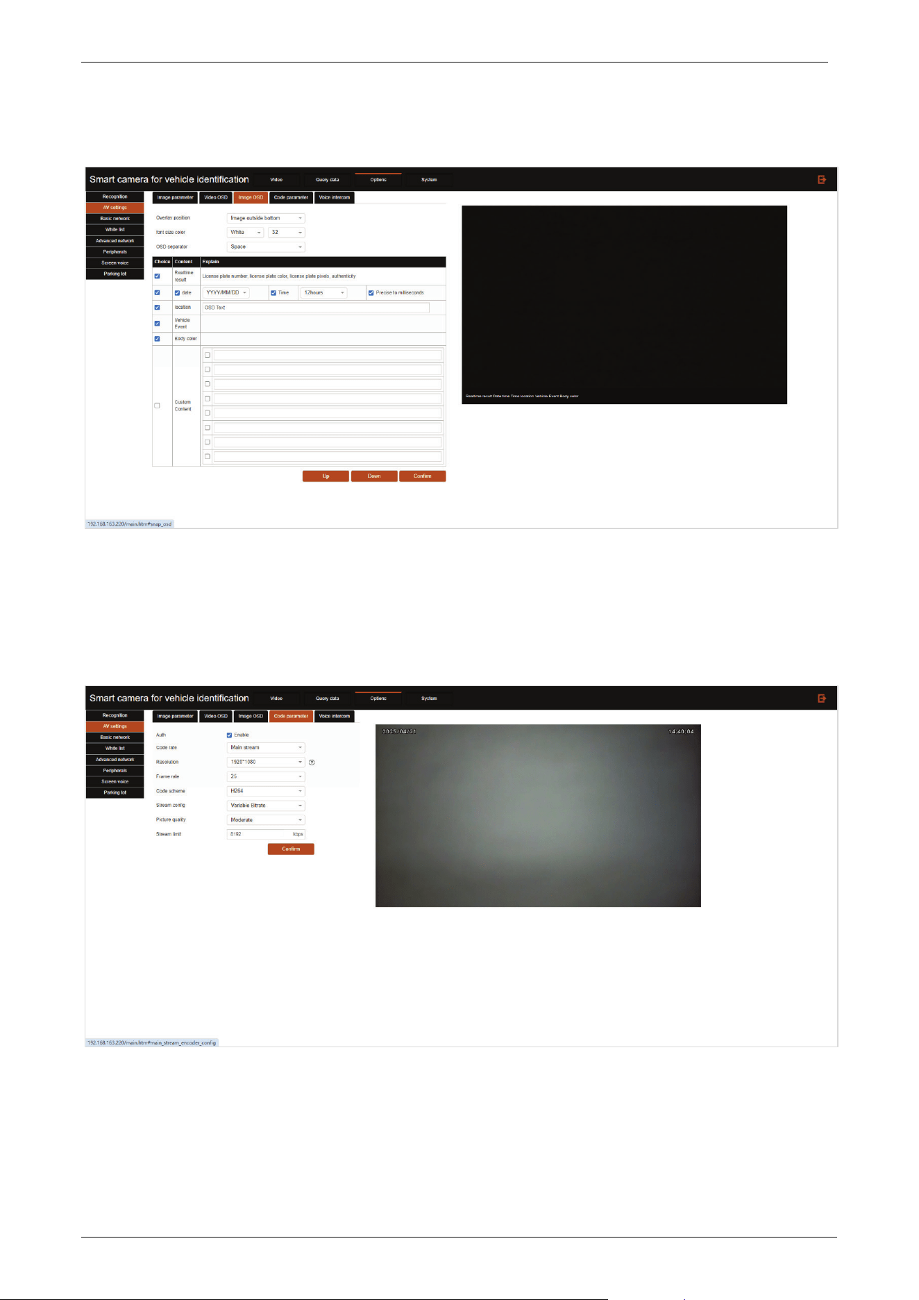
Image OSD
After the camera recognizes the license plate, it will capture a photo and generate some relevant
information in the captured image. Here is the location for setting this information.
Code parameter
Code rate: The camera can output two streams, this option is used to toggle whether the
following configuration item configures the main stream or a sub-stream.
Resolution: Configure the video stream resolution.
E-LPRC500 User Manual
Page | 21 Copyright©2025 ZKTECO. CO., LTD. All rights reserved.
Frame rate: Configure the frame rate of the video stream, you can configure 1~25 frames per
second.
Code scheme: Encoding method of video stream, optional H.264, H.265 (MJPEG is supported on
cell phone).
Stream config: Switch video stream bit rate control mode, fixed code stream is static bit rate
control (CBR), variable code stream is dynamic bit rate control (VBR).
Picture quality: Configure the image quality of the video stream, the clearer the video stream
consumes more network bandwidth.
Stream limit: The code stream cap of dynamic stream. The range is 1~5000kbps.
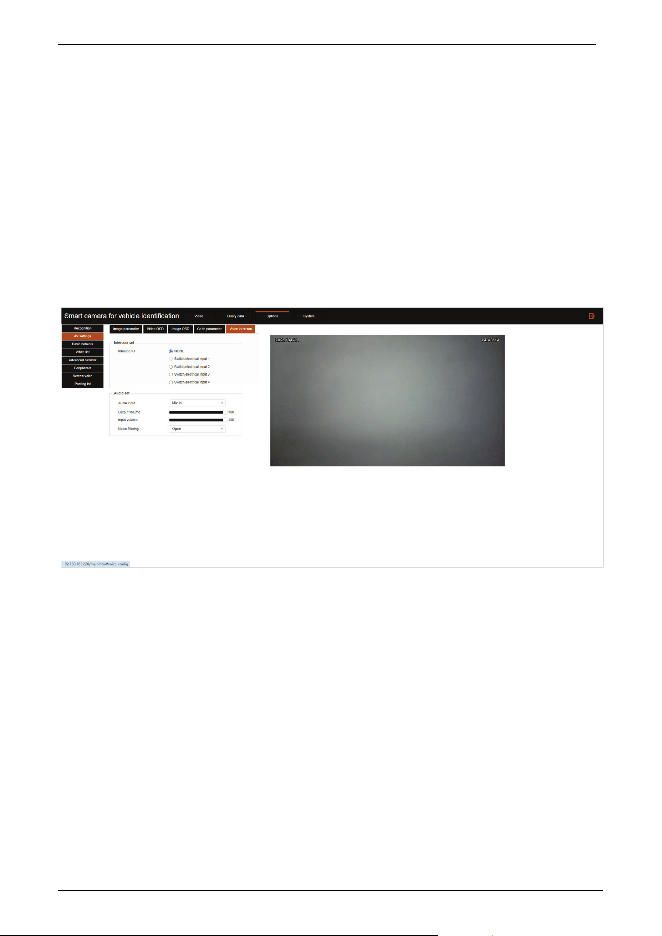
Voice intercom
Intercom set: Set the intercom IO access/no access to the system, if access, select the access port.
Audio input: Set the audio input source.
Output volume: Set the audio volume output from this camera.
Input volume: Set the audio volume of the input device.
Noise filtering: Turn on to perform noise reduction on the pickup sound of the unit.
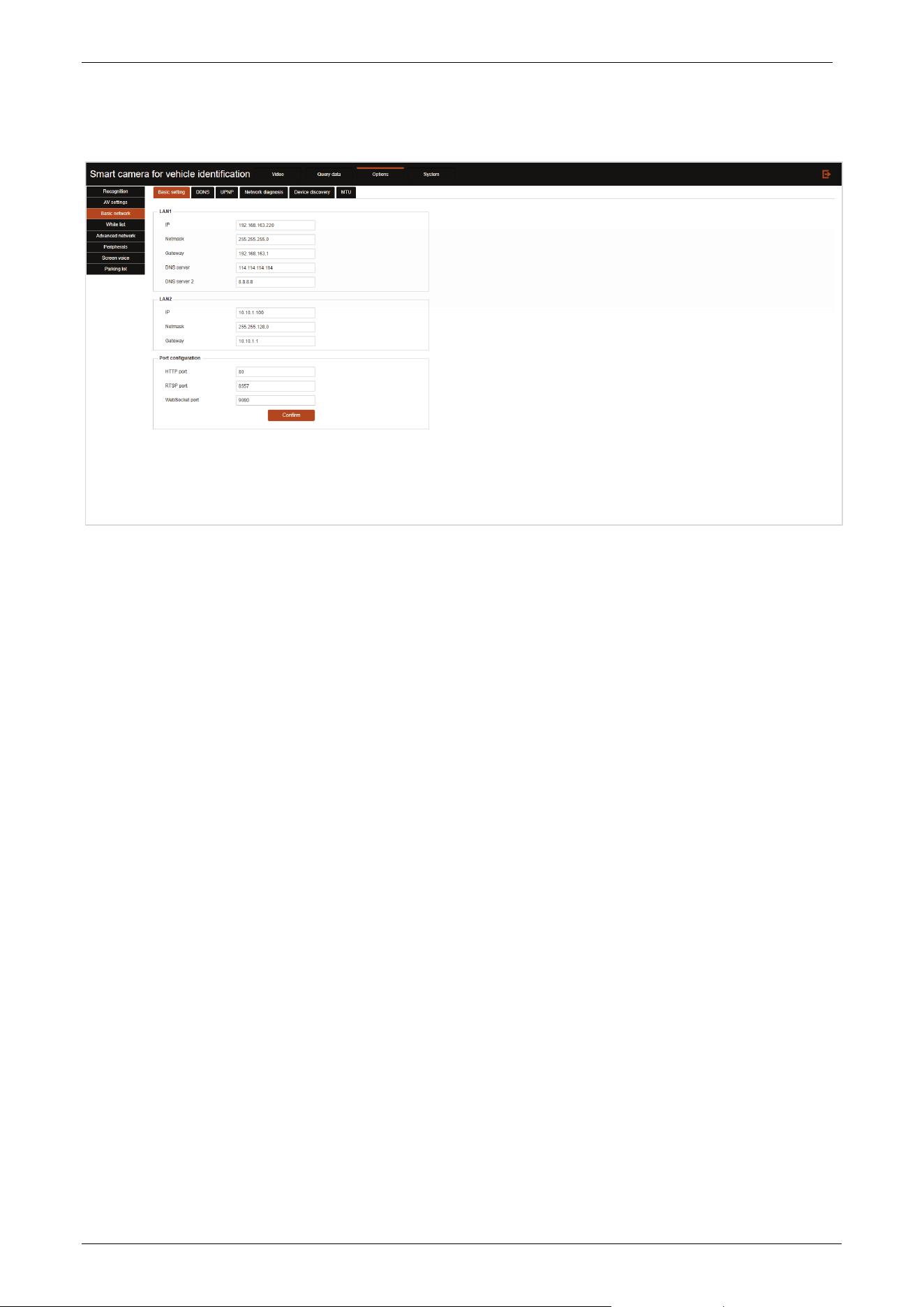
3.3.3 Basic Network
Click the Basic network tab to enter the Basic network settings page.
E-LPRC500 User Manual
Page | 22 Copyright©2025 ZKTECO. CO., LTD. All rights reserved.
Basic setting
• IP: Set the network IP address of LAN1/LAN2.
• Netmask: Set the subnet mask of LAN1/LAN2.
• Gateway: Set the default gateway of LAN1/LAN2, which should be in the same network segment
as the IP address.
• DNS server: Set the DNS server of the network. After setting the network parameters, click
Confirm to take effect.
• DNS server 2: Set an alternate DNS server, and automatically switch to this server when the
connection to the default DNS server fails.
• HTTP port: Set the port number of the HTTP protocol, the default is 80, click Confirm to take effect.
• RTSP port: Set the port number for RTSP transmission video stream, the default is 8557, click
Confirm to take effect.
• WebSocket port: Set the port number of the WebSocket protocol, the default is 9080, click
Confirm to take effect.
Note:
1) After modifying the IP address, the webserver address of the camera is also modified accordingly.
The user needs to type the new IP Address of the camera in the address bar of a web browser to
login again.
2) The modified IP address must be the same as the PC network segment.
E-LPRC500 User Manual
Page | 23 Copyright©2025 ZKTECO. CO., LTD. All rights reserved.
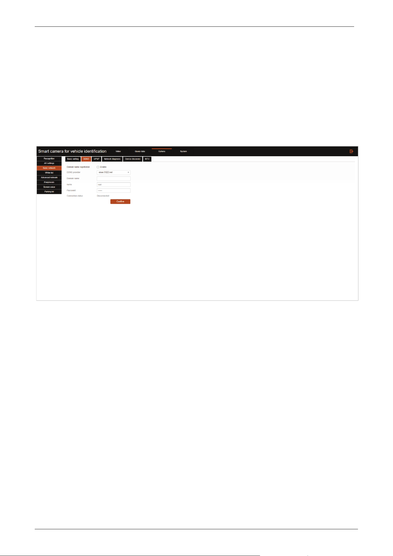
DDNS
DDNS (Dynamic Domain Name) is to map the user's dynamic IP address to a fixed domain name resolution
service, each time the user connects to the network the client program will be through the information
transfer of the host's dynamic IP address to the server program located on the service provider's host, the
server program is responsible for the provision of DNS services and the implementation of dynamic
domain name resolution. This allows direct access to the device via the domain name without the need to
record an IP address that is subject to change.
Domain name registration: Check this checkbox to enable DDNS function.
DDNS provider: The name of the DDNS server provider.
Domain name: The domain name that the user registered with the DDNS service provider.
Name: The user name that the user registered with the DDNS service provider.
Password: The user's password when registering with the DDNS service provider. After the
configuration is complete, click Confirm to take effect.
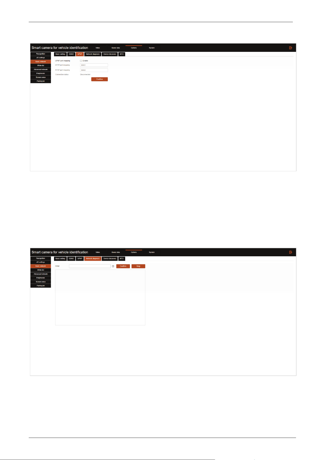
UPNP
The UPNP (Universal Plug and Play) protocol can establish a port mapping relationship between the
router's intranet and extranet, so that users on the extranet can directly access devices on the intranet
through the extranet IP address.
E-LPRC500 User Manual
Page | 24 Copyright©2025 ZKTECO. CO., LTD. All rights reserved.
UPNP port mapping: Check this checkbox to enable UPnP port mapping function.
HTTP port mapping: Configure the external port number for HTTP protocol.
RTSP port mapping: Configure the external port number for RTSP protocol video streaming
transmission. Click Confirm to take effect after the modification is completed.
Network diagnosis
In the input box, you can enter the corresponding network test commands, click Confirm to start
execution, the execution status will be displayed in the blank area below, click Stop to terminate the
execution of the current command.

E-LPRC500 User Manual
Page | 25 Copyright©2025 ZKTECO. CO., LTD. All rights reserved.
Device discovery
Discovery mode: Can be selected as Take the initiative to send or Passive receiving.
Take the initiative: The client initiates a connection proactively, knowing the server's IP address
and port, and initiates a TCP connection based on this information.
Passive receiving: The server passively listens to the port and waits for the client to initiate a
connection. After receiving the connection request from the client, the server accepts the
connection and exchanges data.
MTU
E-LPRC500 User Manual
Page | 26 Copyright©2025 ZKTECO. CO., LTD. All rights reserved.
MTU: The maximum packet size that can be transmitted in a network, measured in bytes.
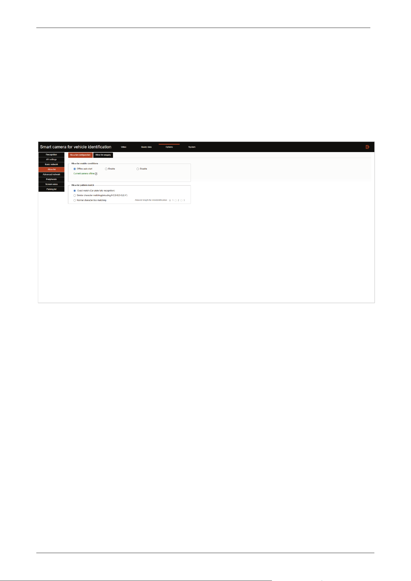
3.3.4 Allow List
Click the Allow list tab to enter the allow list settings page.
Allow list configuration
Allow list enable conditions: You can set Allow list enable status/enable trigger condition.
Allow list pattern match: Can set the query mode of allow list fuzzy matching, users can choose
the appropriate fuzzy query mode according to the actual scene requirements, as well as choose
the corresponding allowable misidentification length according to the scene fault tolerance
requirements.
E-LPRC500 User Manual
Page | 27 Copyright©2025 ZKTECO. CO., LTD. All rights reserved.
Allow list enquiry
Details of the license plate in the allow list can be checked by entering the license plate number.
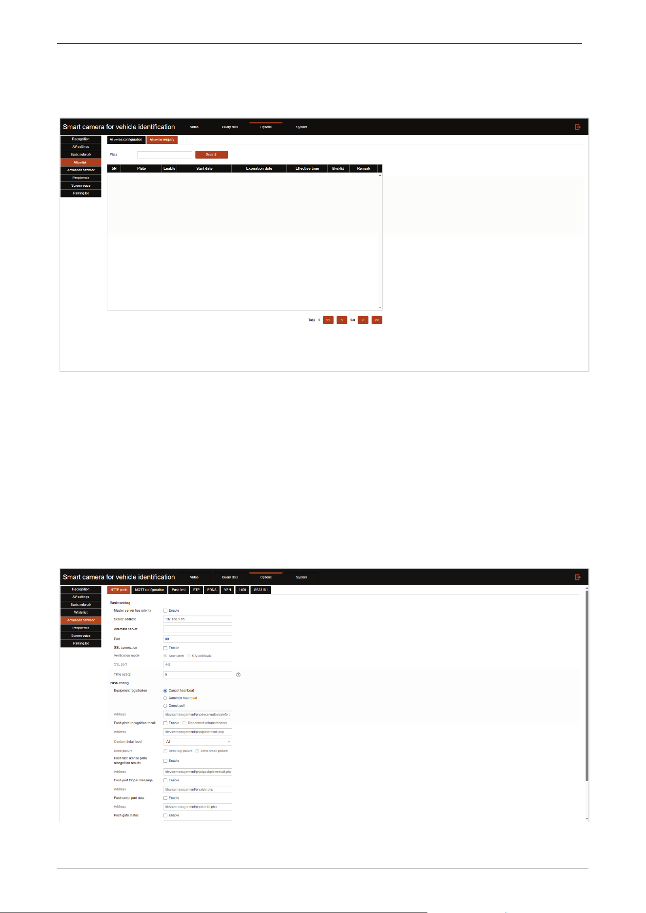
3.3.5 Advanced Network
Click the Advanced network tab to enter the advanced network settings page.
HTTP push
Push configuration is used to configure the back-end to receive image data for license plate capture.

E-LPRC500 User Manual
Page | 28 Copyright©2025 ZKTECO. CO., LTD. All rights reserved.
Master server has priority: Enable to prioritize the master server for push.
Server address: Configure the primary server address to receive uploaded images.
Alternate server: Configure the alternative server address to receive uploaded images, can be
multiple addresses, separated by ';'.
Port: The port number for HTTP/HTTPS upload, default 80.
SSL connection: Checking this checkbox is to enable SSL during data transfer.
Verification mode: SSL authentication method.
Anonymity: Use anonymous SSL authentication.
CA certificate: Use CA certificate for SSL authentication, check the box and upload CA certificate.
SSL port: Configure the port number for SSL authentication.
Time out: Configure the connection timeout time for data push.
Equipment registration: By which to judge the connection between the device and the server.
Cancel heartbeat: Do not judge the connection, send data directly.
Common heartbeat: The client sends heartbeat messages to the server at regular intervals, and
judges the connection between the device and the server by whether the server returns the
message within the specified time.
Comet poll: Based on HTTP long connection, the client sends query request to the server, when
there is no data, the server does not respond immediately, but wait for data. Only when new data
is generated, it responds to the browser, and an HTTP connection ends.
Address: The push URL address of the equipment registration.
Push plate recognition result: Check this checkbox to push plate capture results via HTTP
protocol.
Address: The push URL address of the plate capture result. UTF8 encoding and then base64
encoding.
Content detail level: Select the content to push for the plate capture result.
Send picture: Push captured license plate images, choose to send big picture or small picture.
Push fast license plate recognition result: After enabled, only push a small portion of key data
and quickly push the results to achieve the goal of quickly opening the gate.
Address: The push URL address of the fast plate capture result.
Push port trigger message: Check this checkbox to enable port trigger push content.
Address: the URL address of the port-triggered push. UTF8 encoding followed by base64
encoding.
Push serial port data: Check this checkbox to enable serial port data push.
Address: Serial port triggered push URL address, UTF8 encoded then base64 encoded.
Push gate status: After enabled, when the barrier gate status of the device connection changes, it
will actively push the barrier gate status to the server address.
Address: The push URL address of the gate status.
HTTP offline check: Whether to enable HTTP offline check.
Retransmission times: Configure the number of HTTP push retransmissions.
Click Confirm to save changes.
E-LPRC500 User Manual
Page | 29 Copyright©2025 ZKTECO. CO., LTD. All rights reserved.
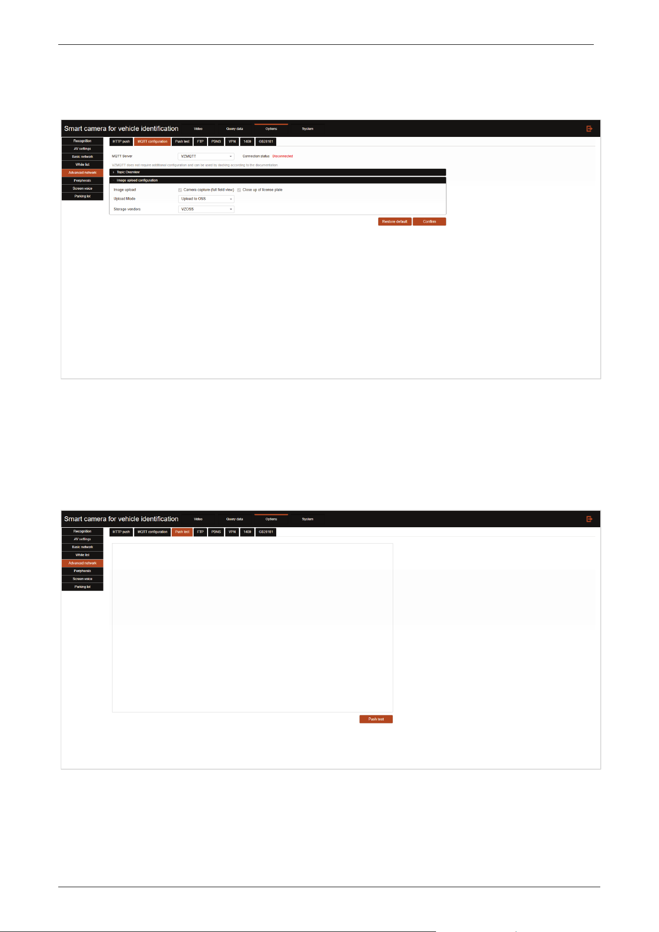
MQTT configuration
MQTT is a message queue that supports publishing and subscribing. Devices can push system information
to the MQTT server, and customers can then subscribe to the information published by the device from
the MQTT server.
Push test
Push test can be performed by clicking the Push test button in the lower right corner, and the test
details will be displayed in the blank area of the interface.
E-LPRC500 User Manual
Page | 30 Copyright©2025 ZKTECO. CO., LTD. All rights reserved.
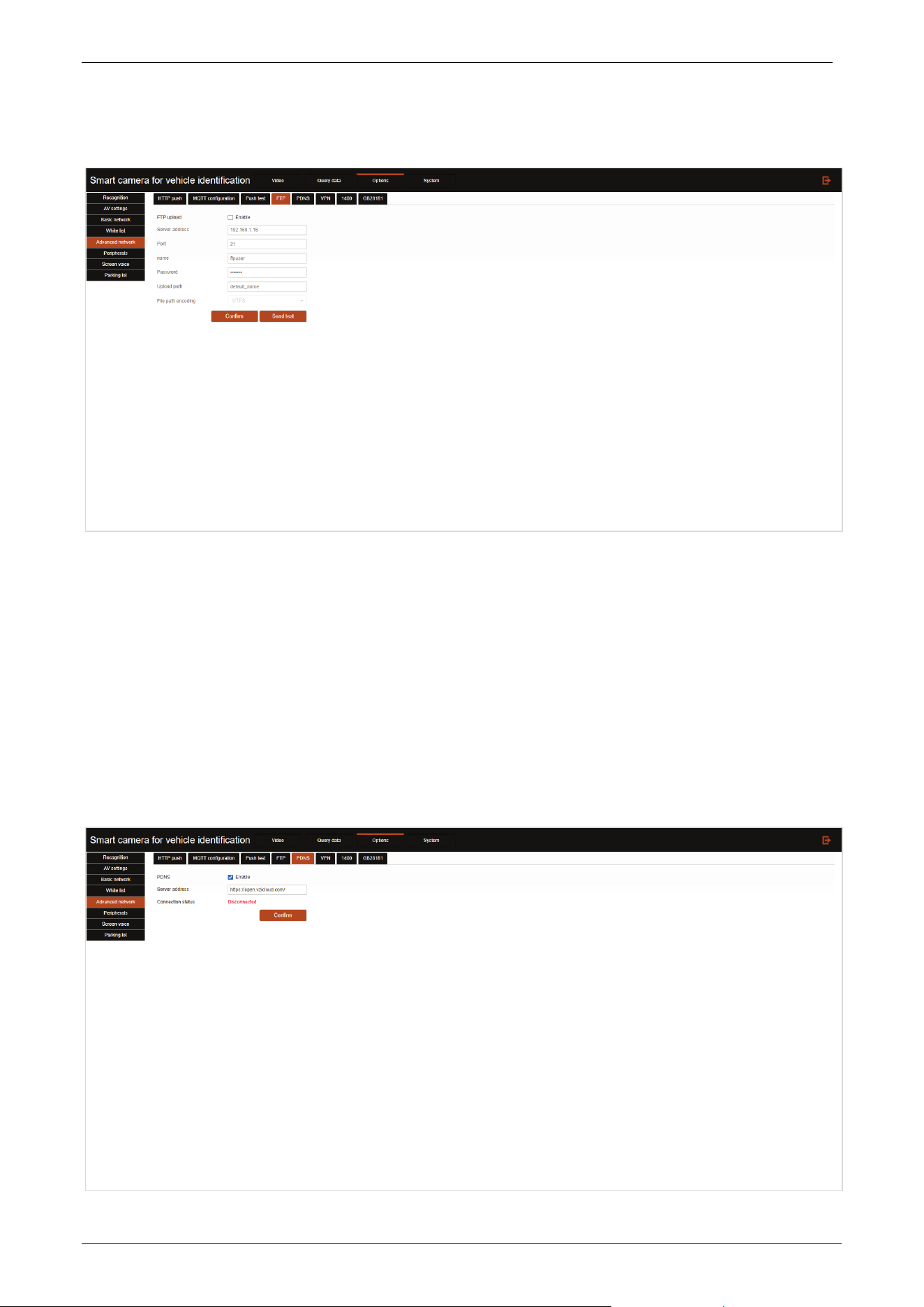
FTP
FTP upload: Check this option to enable FTP upload function.
Server address: Configure the FTP server address for uploading.
Port: Configure the port number of FTP upload service.
Name: Configure the user name used to log in to the FTP server.
Password: Configure the password used to log in to the FTP server.
Upload path: Configure the data path of the uploaded FTP server.
File path encoding: Can be selected as UTF8 or GBK.
PDNS
E-LPRC500 User Manual
Page | 31 Copyright©2025 ZKTECO. CO., LTD. All rights reserved.
PDNS: Check this checkbox to start the PDNS connection function.
Server address: You can configure the PDNS address.
Click the Confirm button to save the configuration.
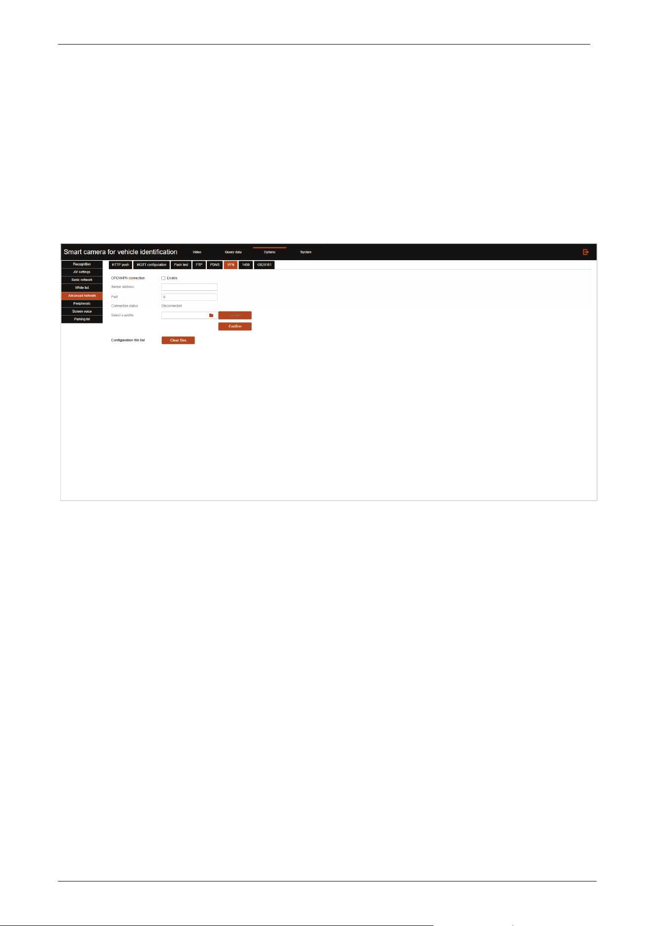
VPN
A VPN is a virtual transport channel that provides a secure and reliable network transport channel for
remote access to devices.
OPENVPN connection: Check this checkbox to enable the Open VPN function.
Server address: You can configure the VPN server address.
Port: Configure the port number of VPN service.
Select a profile: Select the security certificate of Open VPN and click Upload. Click Confirm after
all configurations are completed to take effect.
3.3.6 Peripherals
Click the Peripherals tab to enter the peripherals settings page.
E-LPRC500 User Manual
Page | 32 Copyright©2025 ZKTECO. CO., LTD. All rights reserved.
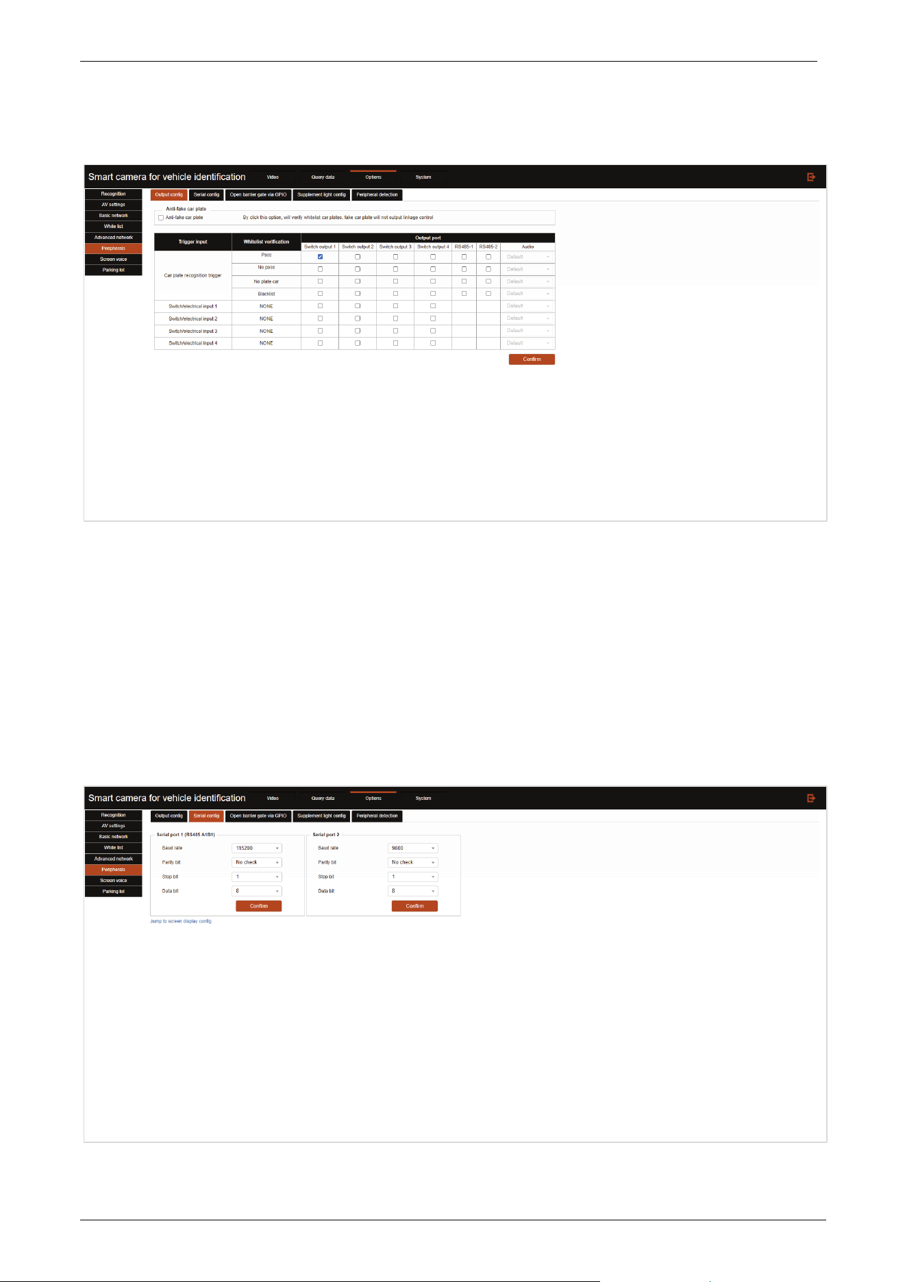
Output config
Anti-fake car plate: When turn on the function, the fake license plate will not trigger the output
linkage control.
User can configure the system to choose to output signals at multiple ports according to the white
list verification when the license plate recognition is triggered.
User can configure the system to trigger multiple (only some output ports are supported) output
port signals when getting input port signals.
Serial config
E-LPRC500 User Manual
Page | 33 Copyright©2025 ZKTECO. CO., LTD. All rights reserved.
Baud rate: Configure the serial port baud rate.
Parity bit: Configure the serial port checksum bit.
Stop bit: Configure the serial port stop bit.
Data bit: Configure the serial port data bit.
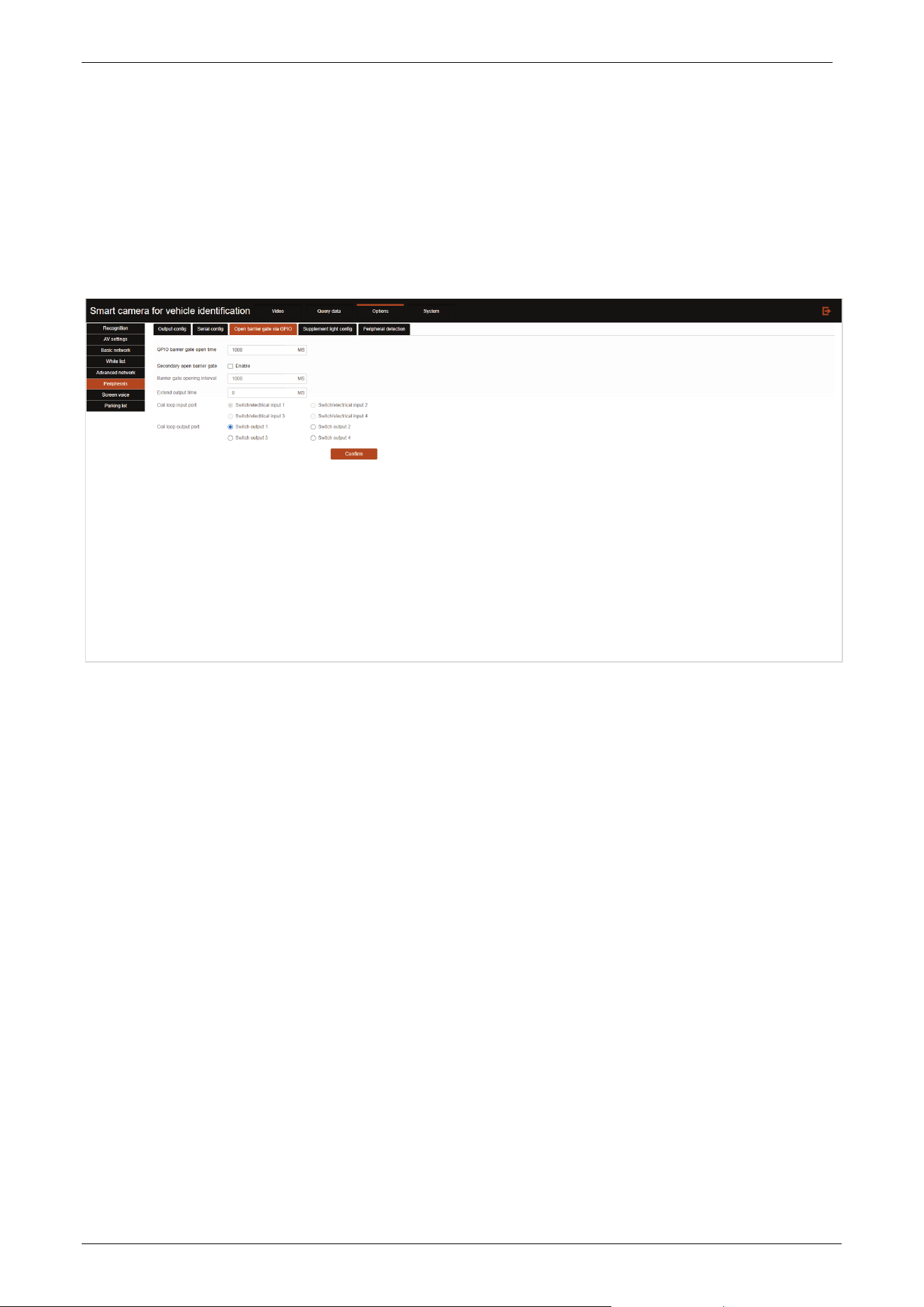
Open barrier gate via GPIO
GPIO barrier gate open time: Sets the length of time a single gate will remain open.
Secondary open barrier gate: Enable to trigger gate opening for vehicles not recognized by the
camera through the ground sensing coil.
Barrier gate opening interval: Set the minimum interval time between two gate openings, only
when the front vehicle passes and the gate drops, the gate can be opened for the rear vehicle after
the interval time has elapsed.
Extend output time: Sets the extension time for the ground sensing coil to respond to the output
signal after the vehicle sensing has disappeared.
Coil loop input port: Sets the interface to receive the signal from the ground sensing coil.
Coil loop output port: Set the interface to output the signal of ground sense coil.
E-LPRC500 User Manual
Page | 34 Copyright©2025 ZKTECO. CO., LTD. All rights reserved.
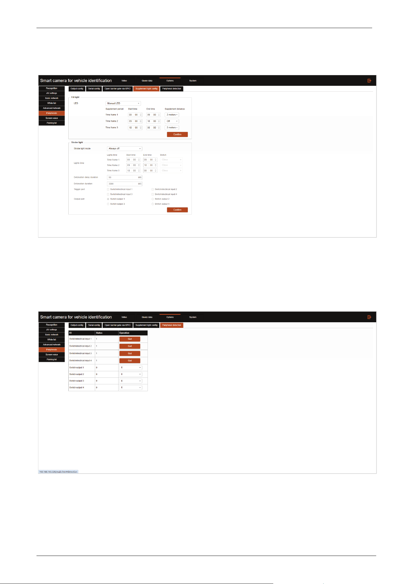
Supplement light config
LED: Select the fill light working status.
Fill light configuration can be set for different time periods by distinguishing time periods.
Peripheral detection
In the input port row, you can click the Get button to get the current port connectivity status.
In the Output Port row, you can set the status of the current port to connected/disconnected.
E-LPRC500 User Manual
Page | 35 Copyright©2025 ZKTECO. CO., LTD. All rights reserved.
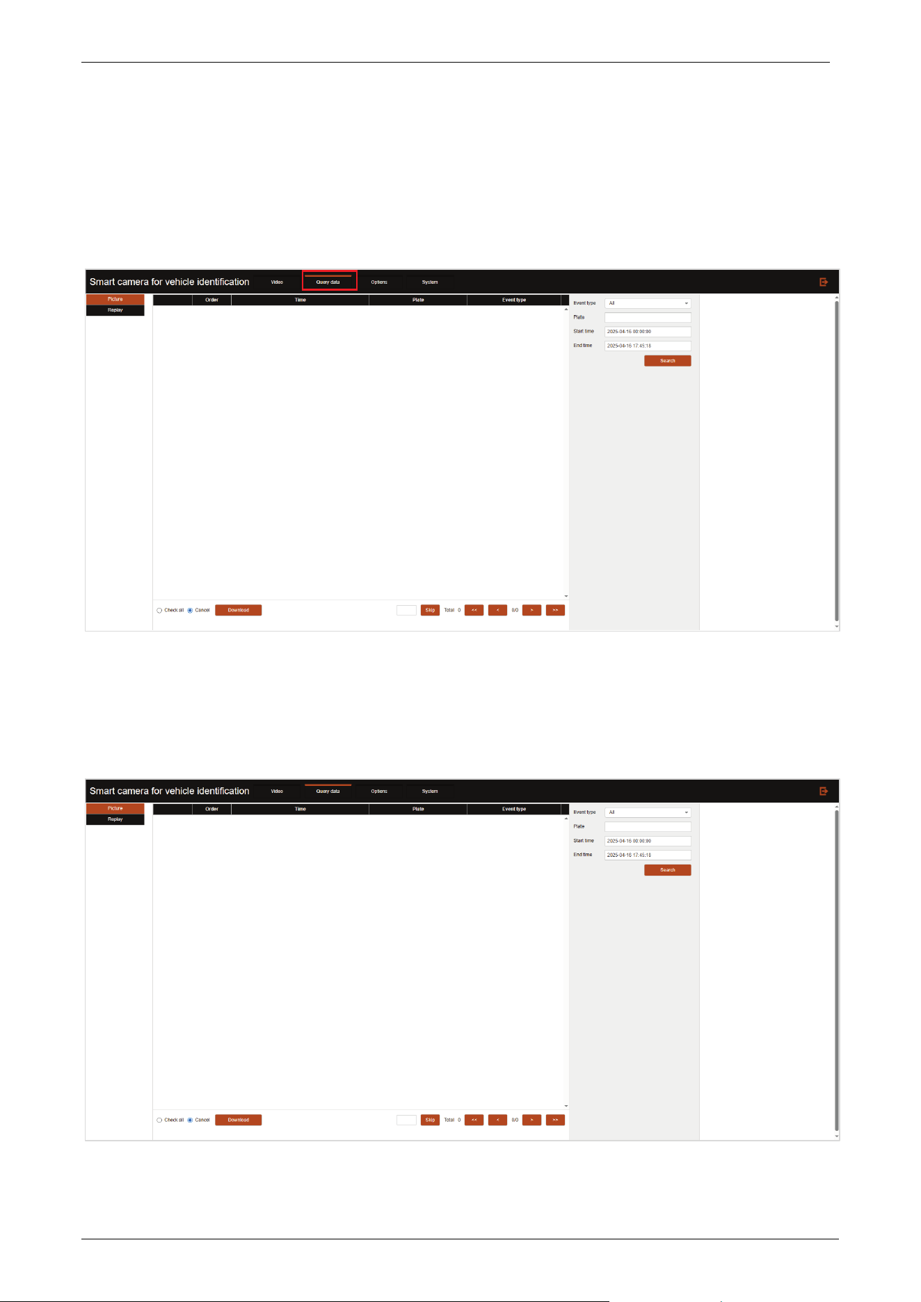
3.4 Query Data
Click [Query data] to enter the data query interface (currently only supports image data query), as
shown below.
3.4.1 Picture
Click Picture to enter the picture preview interface, as shown below.
E-LPRC500 User Manual
Page | 36 Copyright©2025 ZKTECO. CO., LTD. All rights reserved.
You can input the license plate number/time period at the top right of the interface and click the
Search button, the captured images that meet the query criteria will be displayed in the query result
column in days (categorized as folders).
Select the image on the right side of the interface to preview the image.
Click the Download button at the left bottom of the interface to compress and download the
current preview image.
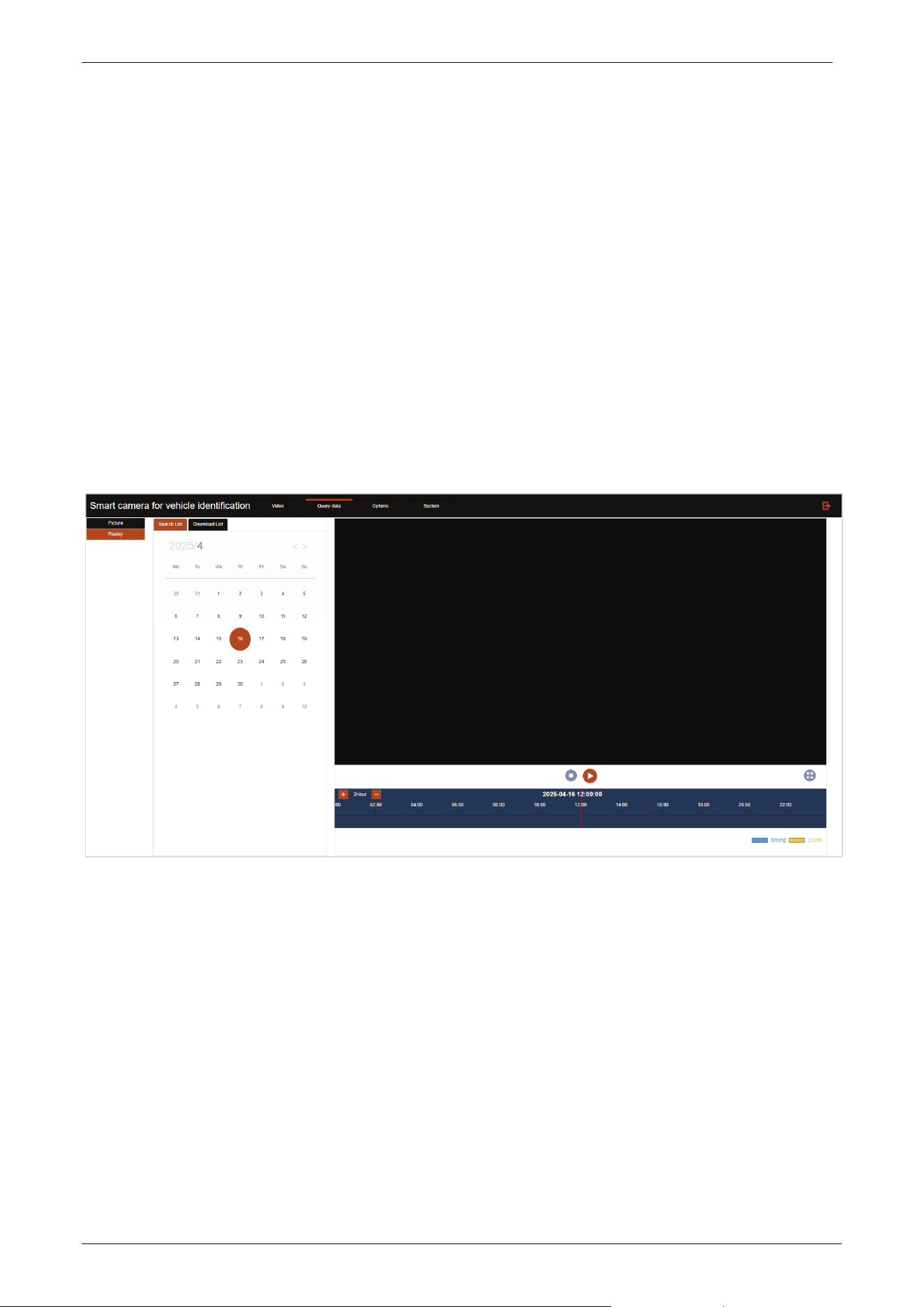
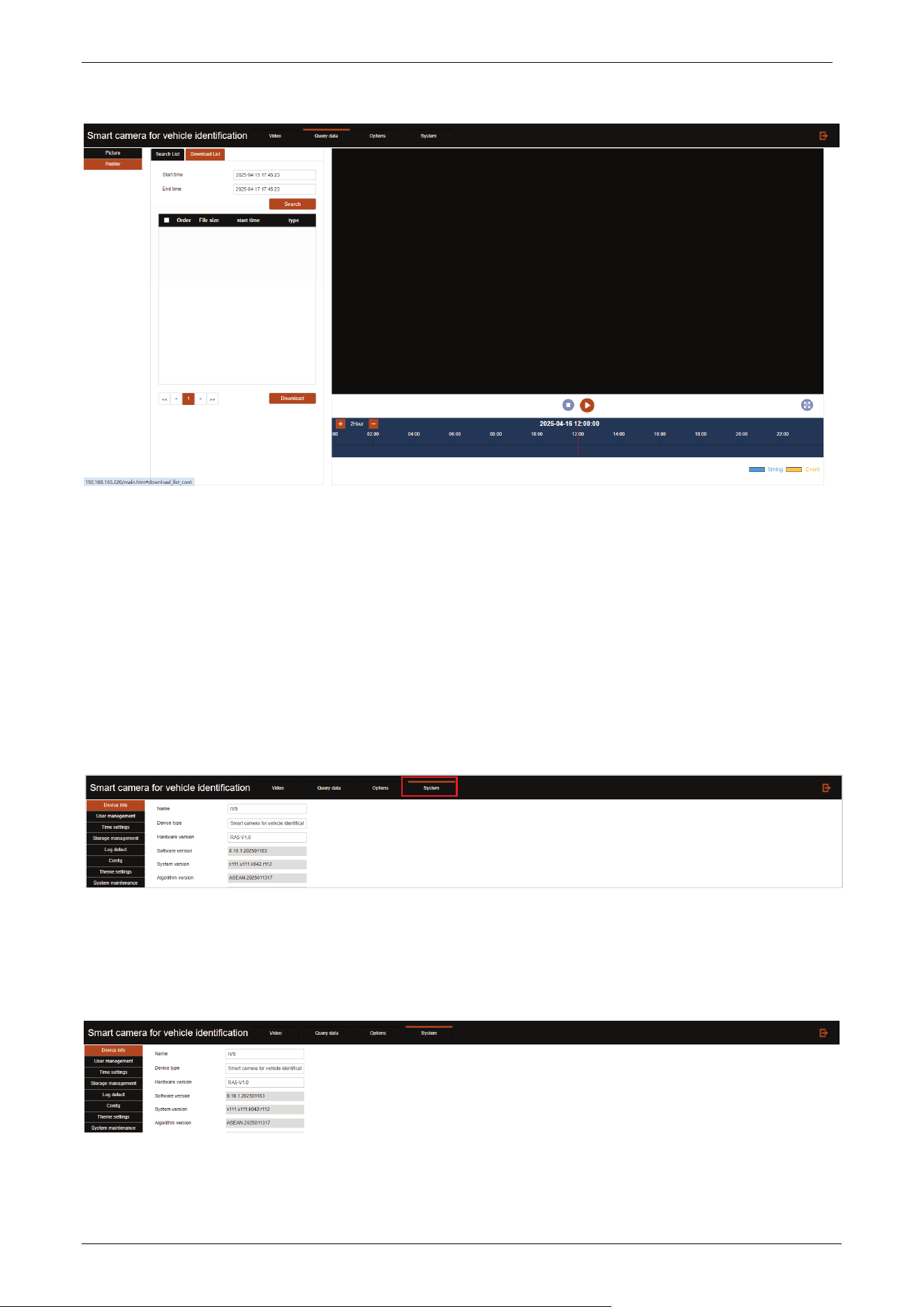
3.4.2 Replay
Click Replay to enter the Video Playback interface, as shown below. Note, please use IE browser to
open.
Search List
On the left side of the video playback page, select the date you want to view the video, and click
“View”, then the recorded video in the right video area will be displayed. Note that you need to
enable the video plan in “System--Storage management--Video program” to view the
corresponding video.
Video playback supports stop, slow playback, fast playback, pause, single frame playback,
screenshot, and video cutting.
Download List
Click the “Download List” tab, the following video query interface will be displayed.
E-LPRC500 User Manual
Page | 37 Copyright©2025 ZKTECO. CO., LTD. All rights reserved.
Set the time you want to download the video, click “Search”, it will search all the videos in that
time.
Check the selected videos, click “Download” in the lower left corner of the interface to start
downloading the selected videos.
3.5 System
Click [System] to enter the device maintenance interface, as shown below:
3.5.1 Device Information
Click Device info to enter the device information display interface.

E-LPRC500 User Manual
Page | 38 Copyright©2025 ZKTECO. CO., LTD. All rights reserved.
3.5.2 User Management
Click User management to enter the user management interface.
To add a user, enter the user name, password, confirm the password, select the type (permission
setting), and click the Confirm button to add the user.
Click Edit in the list of specified user name, enter the password, confirm the password and click OK
to change the user password.
Login timeout: You can set the time to exit the system automatically without operation.
3.5.3 Time Settings
Click Time settings to enter the time settings interface.

E-LPRC500 User Manual
Page | 39 Copyright©2025 ZKTECO. CO., LTD. All rights reserved.
Time zone setting: Configure the time zone in which the current device is located.
Daylight saving time: Select to enable the daylight saving time and set the start and end time.
Manual calibration
Time: This text box shows the current date and time.
Manual calibration: You can directly enter the current date and time.
Local: Select to get the local time to synchronize the device.
NTP synchronize time
Enable: Check the check box to enable NTP time synchronization service.
Server address: Configure the address of NTP server.
Synchronize cycle: Configure the frequency of synchronizing time from NTP server.
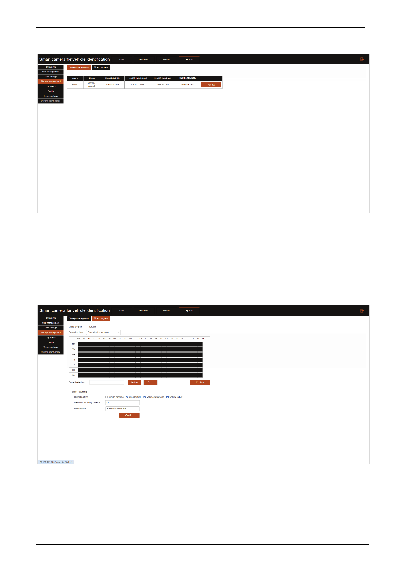
3.5.4 Storage Management
Click Storage management to enter the storage management interface.
E-LPRC500 User Manual
Page | 40 Copyright©2025 ZKTECO. CO., LTD. All rights reserved.
If there are storage devices, the status and capacity information of each storage device will be
displayed in the above figure.
The SD card can be formatted by clicking the Format button on the right.
Click Video program in the storage management interface, you can enter the following video plan
interface, as shown in the following figure.
Click Enable to enable the recording schedule.
Recording type: Can be selected as Encode stream main or Encode stream sub.
Manually set the time for video recording to be enabled, and click Confirm after completing the
setting to take effect.

E-LPRC500 User Manual
Page | 41 Copyright©2025 ZKTECO. CO., LTD. All rights reserved.
Select the event type that the camera automatically record, and set the maximum recording
duration.
3.5.5 Log Detect
Click Log detect to enter the log detect interface.
Check the corresponding log type, you can open the corresponding log service.
Log query and export: Enter the start and end time of the log you want to query, perform log query,
and at the same time, you can export the queried log content.
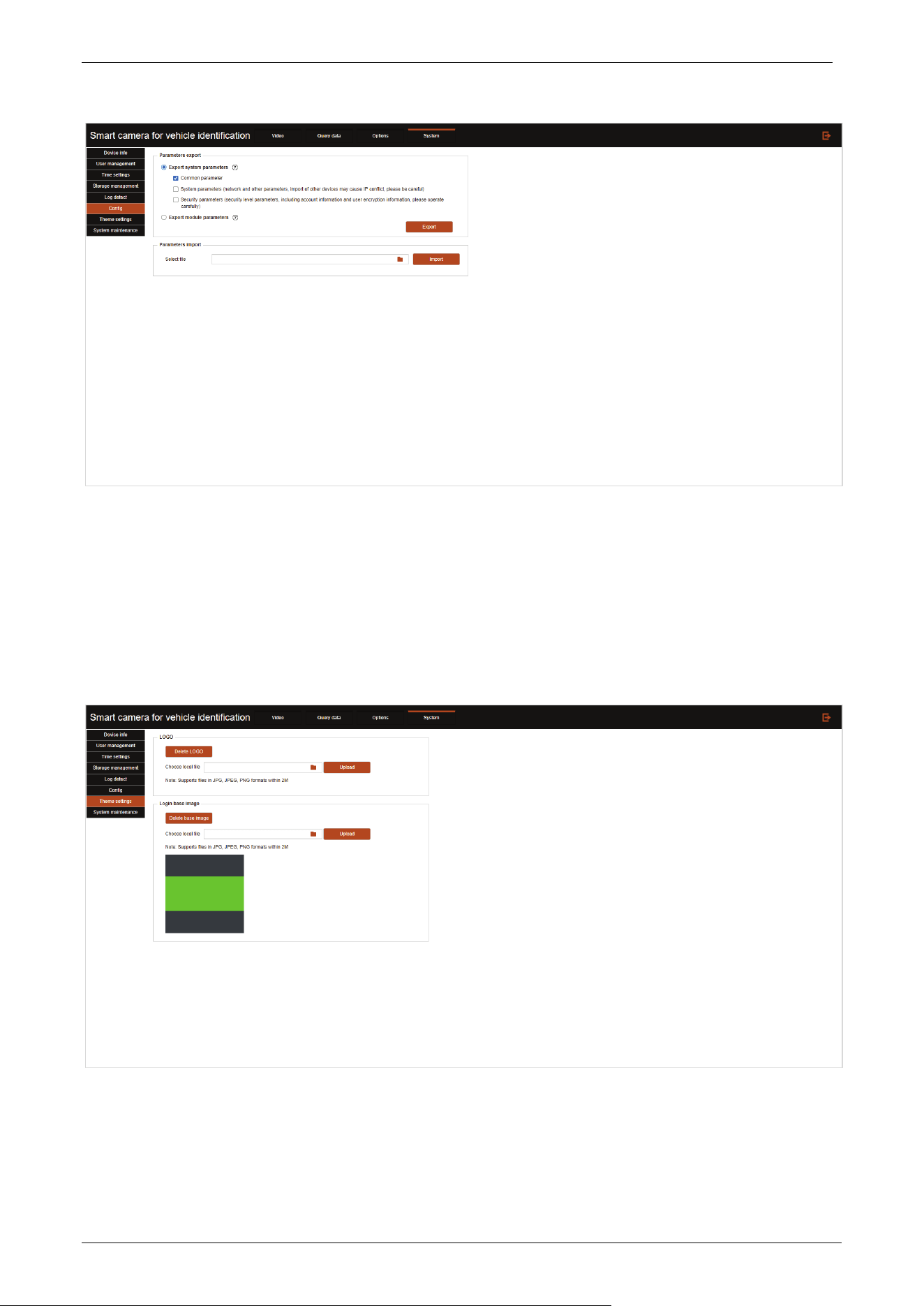
3.5.6 Configuration
Click Config to enter the configuration interface.
E-LPRC500 User Manual
Page | 42 Copyright©2025 ZKTECO. CO., LTD. All rights reserved.
The import and export of camera parameters can export camera related parameter data directly to other
cameras without the need for repeated settings.
3.5.7 Theme Settings
Click Theme settings to enter the theme settings interface.
E-LPRC500 User Manual
Page | 43 Copyright©2025 ZKTECO. CO., LTD. All rights reserved.
LOGO
Upload: After selecting and uploading the corresponding image format LOGO locally, you can add
the corresponding LOGO in the login interface, which will be displayed as shown in the figure
below.
Delete LOGO: Click the Delete LOGO button to clear the logo display on the login screen.
Login base image
The background image of the login interface can be uploaded and changed by yourself.
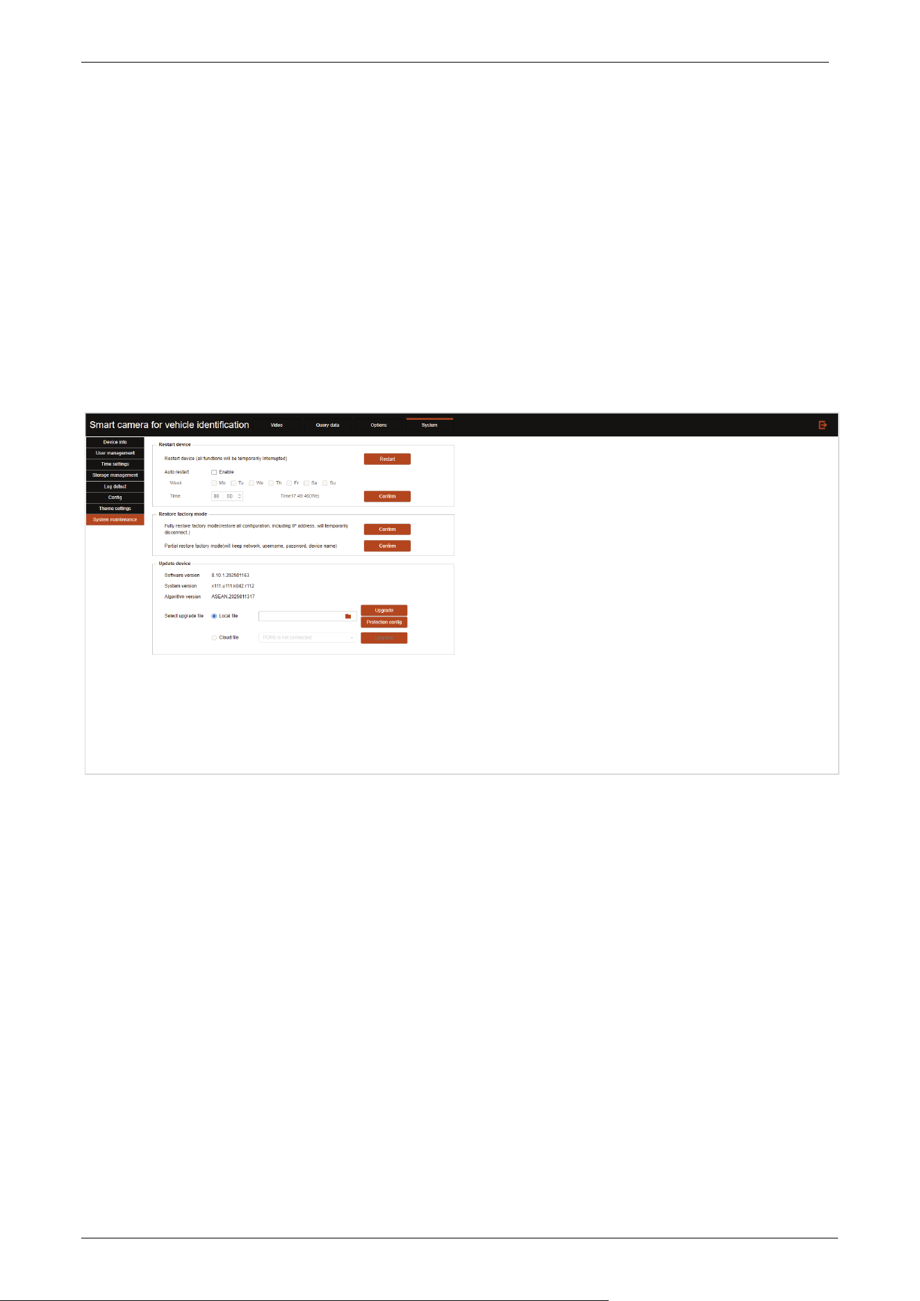
3.5.8 System Maintenance
Click System maintenance to enter the system maintenance interface.
Restart device: Restart button can restart the device immediately, or enable automatic restart to
restart the device at a specific time.
Restore factory mode
Fully restore factory mode: Restore all settings, click Confirm to restore.
Partial restore factory mode: Except that the settings in the prompt are not restored, restore all
other settings, click Confirm to restore.
Update device: Select the upgrade file (.bin) and click Upgrade to remotely update the device
system.

E-LPRC500 User Manual
Page | 44 Copyright©2025 ZKTECO. CO., LTD. All rights reserved.
Q&A
Q: Why the device video cannot be displayed normally?
A: There are several reasons for abnormal display, including:
1. The device is not powered on properly;
2. The network cable is not properly connected or has poor contact;
3. The IP address of the device and the IP address of the PC are not in the same address segment;
4. The network between the device and the client is not connected;
5. The lens cocoon was not removed, or the camera image was obstructed.
When the device cannot display normally, please investigate the above situations one by one.
Q: Remote device setup, but mistakenly set up another device.
A: The possible reason is that the IP addresses of multiple devices within the same local area network
conflict. When multiple devices are used simultaneously, please ensure that there are no IP address
conflicts.
Q: How to do if forget the IP address or username/password?
A: If you forget your IP address, you can use the IP search tool provided with the device to search for it. If
you forget your password, you need to contact our technical support for remote resolution.
Q: Manual capture/recording failed to save locally?
A: Check if the browser is running with administrator privileges. If not, exit and right-click on the browser
to run as administrator.
Q: What are the common problems with web login?
A: 1. After logging into the device, the login interface does not display properly.
Please ensure that the IE version is IE8.0 or above.
2. When logging in through IE browser, there is no video playback in the real-time video interface.
Solution: Refresh the webpage again, and a prompt will pop up to install the control. Once the installation
is complete, you can see the real-time video.
3. Control installation failed.
Go to Features “Control Panel”-“Programs and Features”, uninstall the WebCtrl control, and reinstall it.

ZKTeco Industrial Park, No. 32, Industrial Road,
Tangxia Town, Dongguan, China.
Phone : +86 769 - 82109991
Fax : +86 755 – 89602394
www.zkteco.com
Copyright © 2025 ZKTECO CO., LTD. All Rights Reserved.


