
v. 091709
CL300
Endurance
®
CL300 Climber
User Manual
v. CL300-20230116
by Body-Solid
8
8
8
15
14
10R
10L
95

Table of Contents
2
CONGRATULATIONS..................................................................................3
IMPORTANT SAFETY INSTRUCTION........................................................4
SAFETY GUIDELINES.................................................................................5 - 6
REFERENCE DRAWING.............................................................................7
HARDWARE PACK LIST..............................................................................8
ASSEMBLY INSTRUCTION.........................................................................9 - 21
OPERATING YOUR CLIMBER....................................................................22 - 23
OPERATING THE CONSOLE......................................................................24 - 27
MONITORING YOUR HEART RATE............................................................31
CHEST STRAP OPERATION.......................................................................32
MAINTENANCE............................................................................................33
PART LIST....................................................................................................35 - 38
EXPLODED VIEW DIAGRAM......................................................................39

CONGRATULATIONS
3
Congratulations!!
Thank you for purchasing your new Endurance
Climber.
Using state-of-the-art techniques, robust frame structure and superior
ergonomic design, Endurance Climber set a new standard for excellence. The En-
durance Climber can improve your quality of life by keeping you t and healthy,
increasing your energy levels and enhancing your lifestyle.
Endurance
wants to ensure years of quality workouts with your new Climber so we
recommend that you read this manual carefully and thoroughly to fully
understand proper use and maintenance of this product. Retain this Owner’s
Manual for future reference.
Please use this Owner’s Manual to make sure that all parts have been included in
your shipment. When ordering parts, you must use the part number and description
from this Owner’s Manual. Use only Endurance
replacement parts when servicing
this machine. Failure to do so will void your warranty and could result in personal
injury.
For information about product operation or service, check out the ocial
website at www.bodysolid.com/Home/Endurance-Cardio or contact an authorized
dealer or a factory-authorized service company or contact Customer Tech Support
at one of the following:
Toll Free: 1-800-556-3113
Phone: 1-708-427-3555
Fax: 1-708-427-3556
Hours: M-F 8:30-5:00 CST
E-Mail: [email protected]
Or write to:
Endurance Service Department
1900 S. Des Plaines Ave.
Forest Park, IL 60130 USA

Before beginning any tness program, you should obtain a complete physical examination
from your physician.
Il est conseille de subir un examen medical complet avant d’entreprendre tout programme d’exercise. Si vous
avez des etourdissements ou des faiblesses, arretez les exercices immediatement.
When using exercise equipment, you should always take basic precautions,
including the following:
Read all instructions before using the CL300. These instructions are written to
ensure your safety and to protect the unit.
Do not allow children on or near the equipment.
Use the equipment only for its intended purpose as described in this guide.
Do not use accessory attachments that are not recommended by the manufacturer.
Such attachments might cause injuries.
Wear proper exercise clothing and shoes for your workout, no loose clothing.
Use care when getting on or o the unit.
Do not overexert yourself or work to exhaustion.
If you feel any pain or abnormal symptoms, stop your workout immediately and
consult your physician.
Never operate the unit after it has been dropped or damaged.
Return the equipment to a service center for examination and repair.
Never drop or insert objects into any opening in the equipment.
Always check the unit before each use.
Make sure that all fasteners are secure and in good working condition.
Do not use the equipment outdoors or near water.
Personal safety During assembly
It is strongly recommended that a qualied dealer assemble the equipment.
Assistance is required.
Before beginning assembly, please take the time to read the instructions thoroughly.
Read each step in the assembly instructions and follow the steps in sequence.
Do not skip ahead. If you skip ahead, you may learn later that you have to
disassemble components and that you may have damaged the equipment.
Assemble and operate the CL300 on a solid, level surface.
Locate the unit a few feet from the walls or furniture to provide easy access.
The CL300 is designed for your enjoyment. By following these precautions and using com-
mon sense, you will have many safe and pleasurable hours of healthful exercise with your
Endurance
CL300.
After assembly, you should check all functions to ensure correct operation. If you experience
problems, rst recheck the assembly instructions to locate any possible errors made during
assembly. If you are unable to correct the problem, call the dealer from whom you purchased
the machine or call 1-800-556-3113 for the dealer nearest you.
Important Safety Instructions
4

Successful cardio training programs have one prominent feature in common...safety.
Cardio training has some inherent dangers, as do all physical activities.
The chance of injury can be greatly reduced or completely removed by using correct
running techniques, proper breathing, maintaining equipment in good working
condition, and by wearing the appropriate clothing.
It is highly recommended that you consult your physician before beginning
any exercise program. This is especially important for individuals over the
age of 35, or persons with pre-existing health problems.
Always warm up before starting a workout. Try to do a total body warm up
before you start. It is especially important to warm up the specic muscle
groups you are going to be using. This can be as simple as performing a
warm up set of high repetitions and light weight for each exercise.
Always wear appropriate clothing and shoes when exercising.
Wearing comfortable athletic shoes with good support and loose tting,
breathable clothing will reduce the risk of injury.
Maintaining equipment in proper operating condition is of utmost
importance for a safe cardio training program.
Read and study all warning labels on this machine. It is absolutely
necessary that you familiarize yourself and all others with the proper
operation of this machine prior to use.
Keep hands, limbs, loose clothing and long hair well out of the way of all
moving parts.
Inspect the machine daily for loose or worn parts. If a problem is found do
not allow the machine to be used until all parts are tightened or worn or
defective parts are repaired or replaced.
Safety Guidelines
5

This exercise equipment is designed and built for optimum safety for home use.
However, certain precautions always apply whenever you operate any exercise
equipment.
Be sure to read the entire manual before assembly and operation of this machine.
Also, please note the following safety precautions.
MECHANICAL SAFETY
Inspect the equipment prior to exercising to ensure that all nuts and bolts are
fully tightened before each use.
Replace any defective components immediately and/or keep the equipment out
of use until repair.
Do not use attachments not recommended by the manufacturer.
Never drop or insert an object into any opening.
Only one person may use the Climber at a time.
Never activate the Climber when someone is standing on the belt.
APPROPRIATE ATTIRE
Always wear appropriate clothing.
Do not wear loose clothing that might catch on any part of this Climber.
Always wear non-slippery shoes while working with the Climber.
Do not wear shoes with heels or leather soles.
Check the soles of your shoes and remove any dirt and embedded stones.
CHILDREN AND PETS
Most exercise equipment is not recommended for small children.
Children should not use the equipment unless they are under strict adult supervision.
To ensure safety, keep young children o the Climber at all times.
Exercise equipment has many moving parts.
In the interest of safety, keep others (especially children and pets) at a safe distance
while you exercise.
FCC WARNING - POSSIBLE RADIO/TELEVISION INTERFERENCE
NOTE: This equipment has been tested and found to comply with Part 15 of the FCC rules. These limits are designed to
provide reasonable protection against harmful interference in a residential installation. Any changes or modications not
expressly approved by the party responsible for the compliance could void the user’s authority to operate the equipment.
This equipment generates, uses and can radiate radio frequency energy and, if not installed and used in accordance
with the instructions, may cause harmful interference to radio communications. However, there is no guarantee that the
interference will not occur in a particular installation.
If this equipment does cause harmful radio interference to radio or television reception, which can be determined by
turning the equipment o and on, you are encouraged to try to correct the interference by one or more of the following
measures:
Class R (Residential): Private or non-commercial use
• Reorient or relocate the receiving antenna
• Increase space between the equipment
• Plug the equipment into two electrical outlet located on separate circuits
• Consult an exercise equipment dealer or an experienced radio/TV technician for help
Safety Guidelines
6
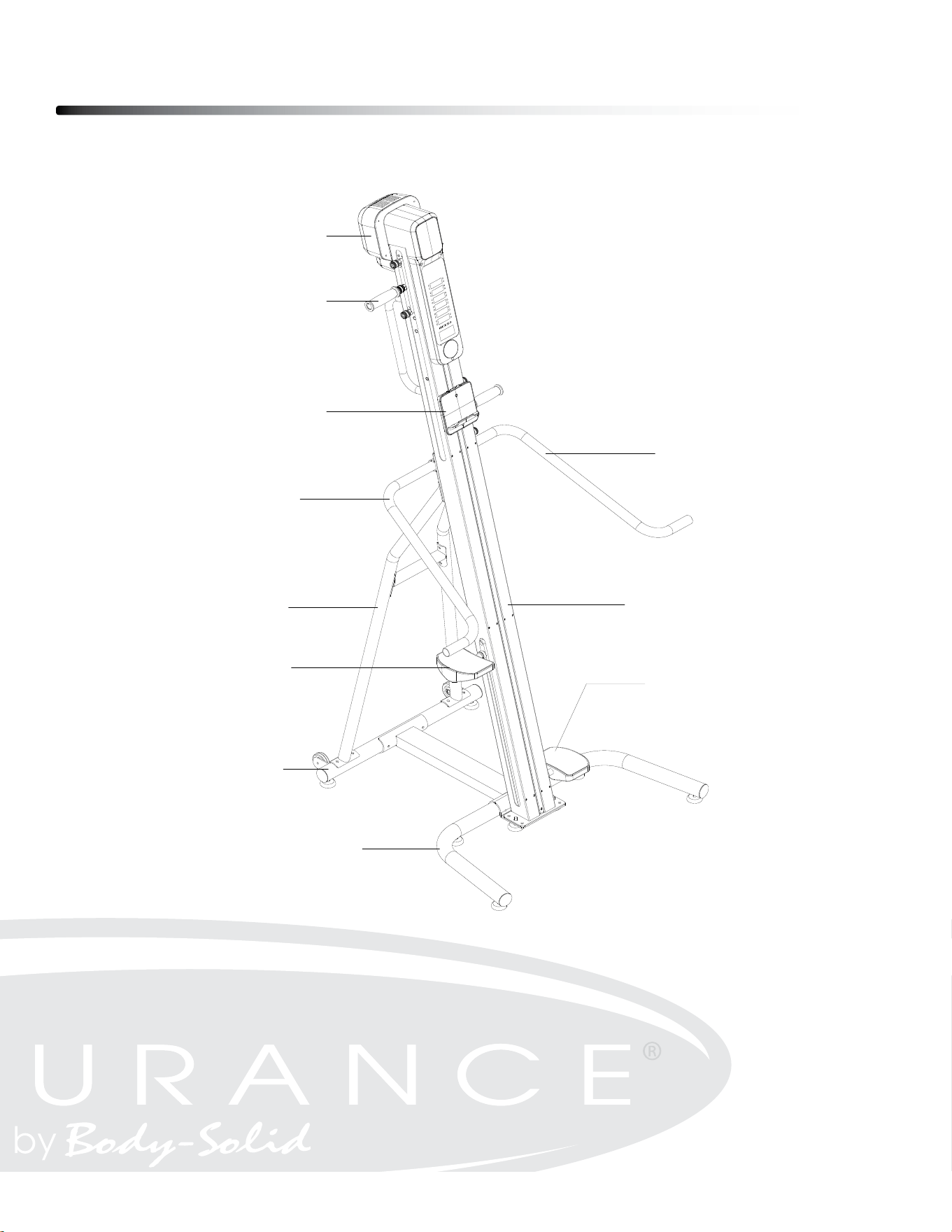
Reference Drawing
7
7
BEFORE YOU BEGIN
ThankyouforchoosingtheCLIMBER.Wetakegreatpridein
producingthisqualityproductandhopeitwillprovidemany
hoursofqualityexercisetomakeyoufeelbetter,lookbetter,
andenjoylifetoitsfullest.
It'safactthataregularexerciseprogramcanimproveyour
physicalandmentalhealth.Toooften,ourbusylifestyleslimit
ourtimeandopportunitytoexercise.
TheCLIMBERprovidesaconvenientandsimplemethodto
beginyourjourneyofgettingyourbodyinshapeand
achievingahappierandhealthierlifestyle.
Beforereadingfurther,pleasereviewthedrawingbelowand
familiarizeyourselfwiththepartsthatarelabeled.Readthis
manualcarefullybeforeusingthe CLIMBER.
ConsoleMonitor
Handlebar
TabletHolder
LeftSideHandrail
RightSideHandrail
LeftRearSupport
MainFrame
RightPedal
LeftPedal
RearStabilizer
FrontStabilizer
Hardware Pack List
8
ϭϬ
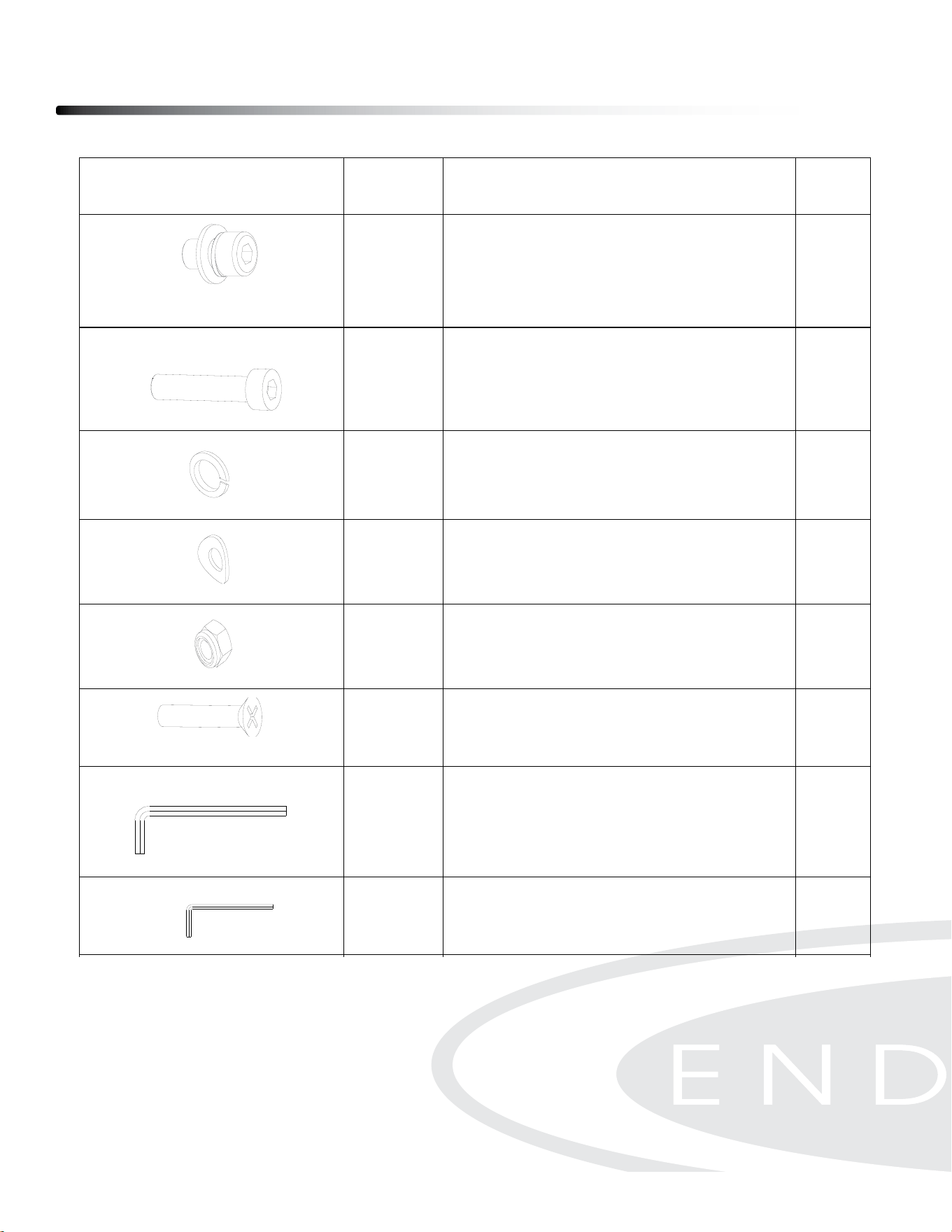
HARDWARE IDENTIFICATION CHART
After unpacking the unit, open the hardware bag and make sure that you have all the
following fasteners. Some fasteners may be already attached to the parts.
Picture Parts
Description Qty
109
Pre-assembled Socket Head Cap
Screw, M8x14mm
(include Spring Washer & Flat
Washer)
24 pcs
105 Socket Head Cap Screw, M8x70mm
4 pcs
106 Spring Washer, M8
4 pc
107 Arc Washer, M8
6 pc
74 Nylon Nut, M8
2 pc
81 Phillips Flat Head Screw, M5x30mm
2 pc
88 Allen Wrench 6mm
1 pc
89 Allen Wrench 4mm
1 pc
91
Open End Wrench 13-15-17mm
1 pc
Assembly Instruction
9
Assembly of the CL300 takes professional installers about 1/2 hour to complete. If
this is the rst time you have assembled this type of equipment, plan on signicantly
more time.
Professional installers are highly recommended!
However, if you acquire the appropriate tools, obtain assistance, and follow the
assembly steps sequentially, the process will take time, but is fairly easy.
ASSEMBLY TIPS
Read all “NoteS” on each page before beginning each step.
While you may be able to assemble the CL300 using the illustrations only, important safety
notes and other tips are included in the text.
Some pieces may have extra holes that you will not use. Use only those holes indicated in
the instructions and illustrations.
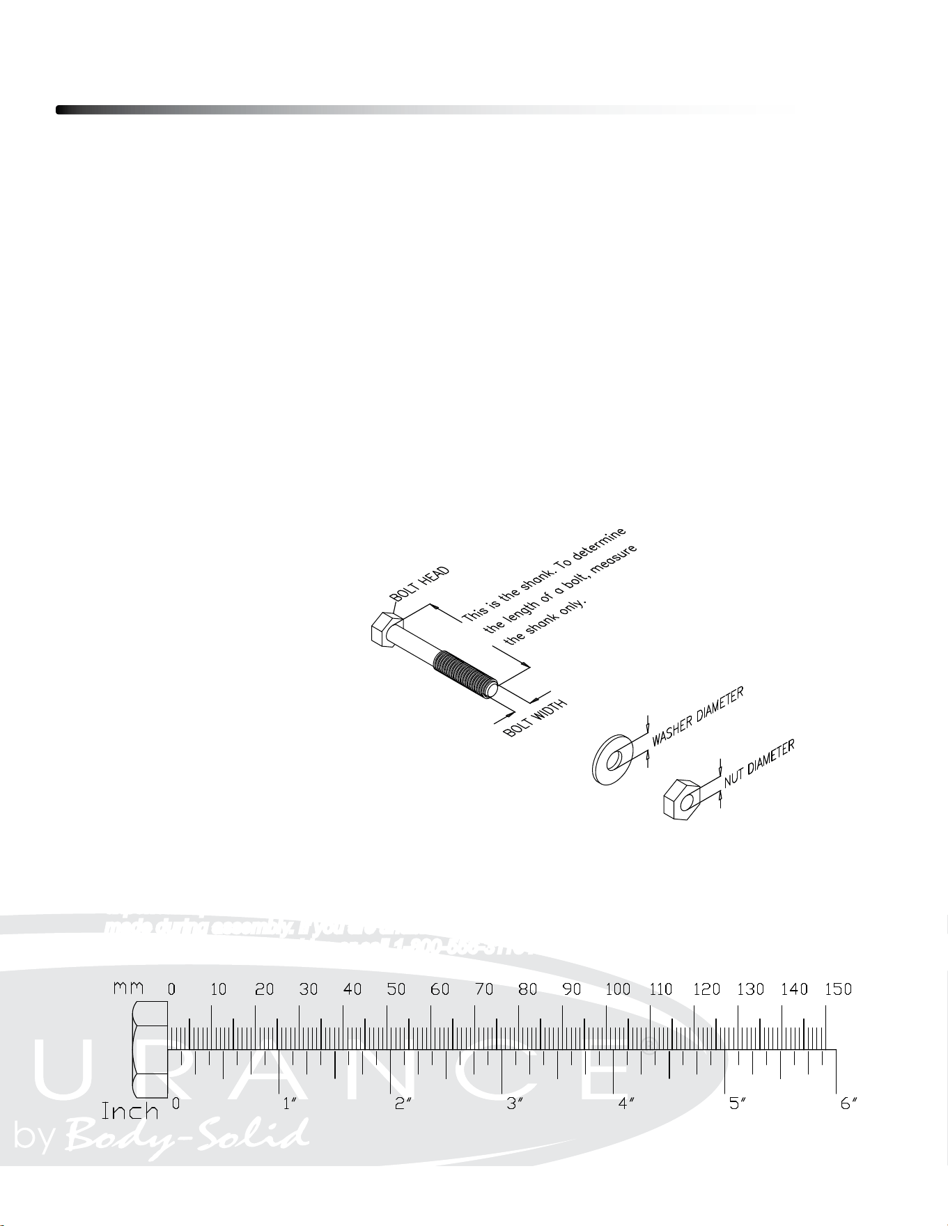
Note: To nd out the length of a particular bolt, measure its shank (the long, narrow part
beneath the head).
Refer to the following diagram:
Do not fully tighten bolts until instructed to do so.
Note: After assembly, you should check all functions to ensure correct operation. If you
experience problems, rst recheck the assembly instructions to locate any possible errors
made during assembly. If you are unable to correct the problem, call the dealer from whom
you purchased the machine or call 1-800-556-3113 for the dealer nearest you.

Be careful to assemble all components
in the sequence they are presented.
Note: Fully tighten bolts at the End of Step 1B.
1A. Attach Front Stabilizer (#2) to Center Connection Tube (#4) using:
m8x70mm socket Head Cap screw (#105), Qty: 2
m8 lock Washer (#106), Qty: 2
m8 arc Washer (#107), Qty: 2
1B. Attach Rear Stabilizer (#2) to Center Connection Tube (#4) using:
m8x70mm socket Head Cap screw (#105), Qty: 2
m8 lock Washer (#106), Qty: 2
m8 arc Washer (#107), Qty: 2
10
Step 1
Step 1
11
Above shows STEP 1 assembled and completed.
ϭϮ
ASSEMBLY INSTRUCTION
STEP 1
Open the carton and take out all the components.
Attach the Front Stabilizer (3) to the Base
Connection Tube (4) by using: 2 pcs of Socket Head
Cap Screw, M8x70mm (105), Spring Washer M8
(106), Nylon Nut M8 (74), and 4 pcs of Arc Washer
M8 (107).
STEP 2
Attach the Rear Stabilizer (2) to the Base
Connection Tube (4) by using: 2 pcs of Socket Head
Cap Screw, M8x70mm (105), Spring Washer M8
(106), and Arc Washer M8 (107).
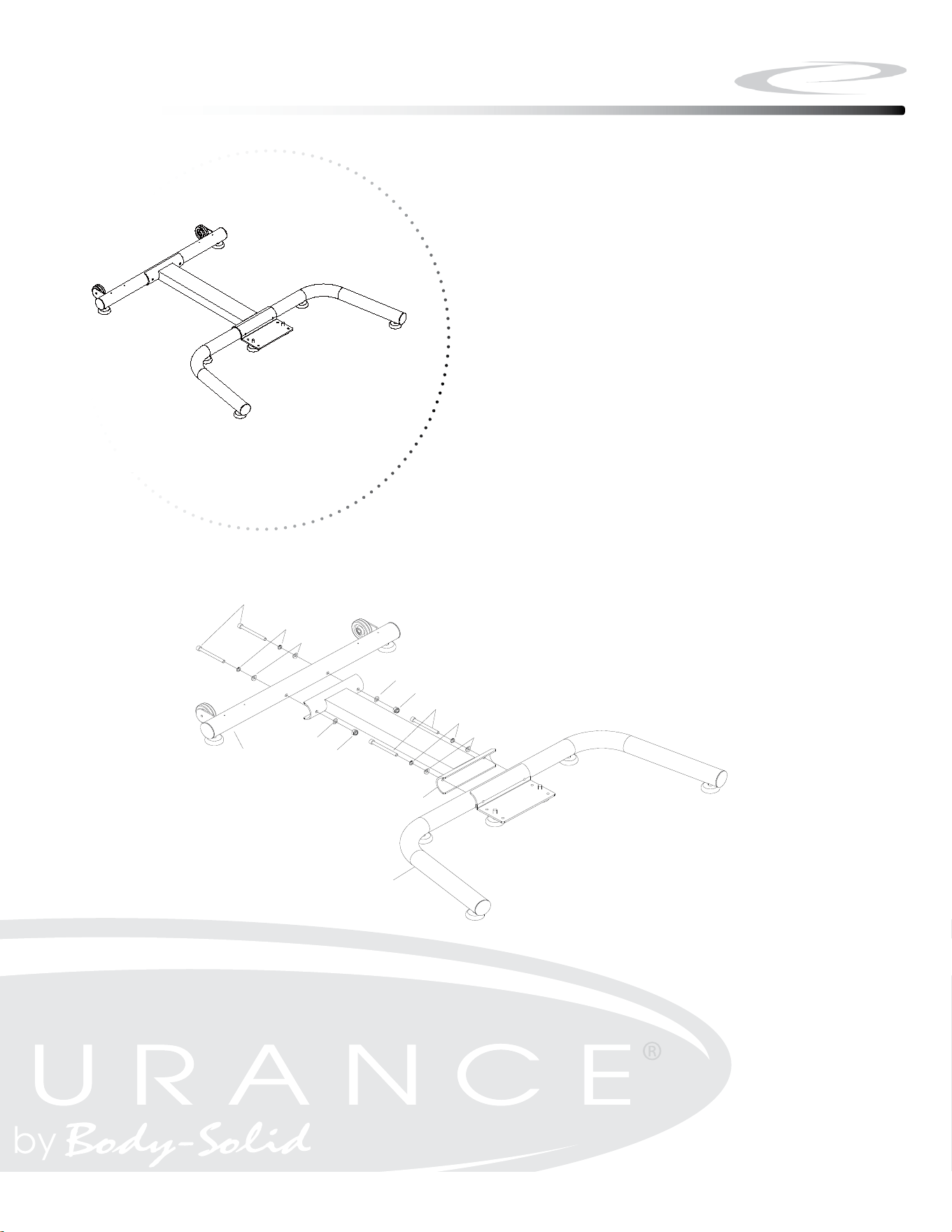
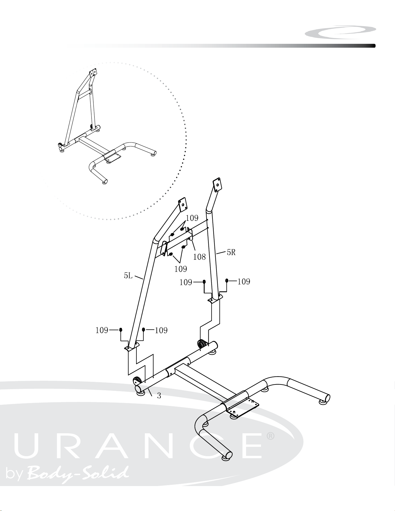
STEP 3
Attach the Support Connection Tube (108) to the
Left / Right Support Tube (5L/ 5R) by using: 4 pcs
of Pre-assembled Socket Head Cap Screw,
M8x14mm (109).
NOTE: Do NOT fully tighten the screws in this step.
2
3
4
105
106
107
107
74
107
74
105
106
107
109
109
5L
5R
108
106
107
107
2
4
107
74
74
106
105
105
107
3

Be careful to assemble all components
in the sequence they are presented.
Note: Do not fully tighten bolts until instructed
2A. Attach Left/Right Support Tube (#5L & #5R) to Support Connection
Tube (#108) using:
m8x14mm socket Head Cap screw with Washers (#109), Qty: 4
2B. Attach Left/Right Support Tube (#5L & #5R) to Rear Stabilizer (#3) using:
m8x14mm socket Head Cap screw with Washers (#109), Qty: 4
12
Step 2
Step 2
13
Above shows STEP 2 assembled and completed.

Be careful to assemble all components
in the sequence they are presented.
Note: Do not fully tighten bolts until instructed
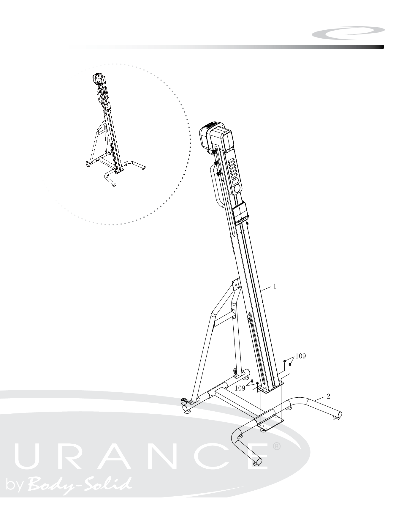
3A. Attach Main Frame (#1) to Front Stabilizer (#2) using:
m8x14mm socket Head Cap screw with Washers (#109), Qty: 4
Note: Please have at least two persons to lift and hold the Main
Frame (#1) during this Step.
14
Step 3
Step 3
15
Above shows STEP 3 assembled and completed.
2
1
109
109

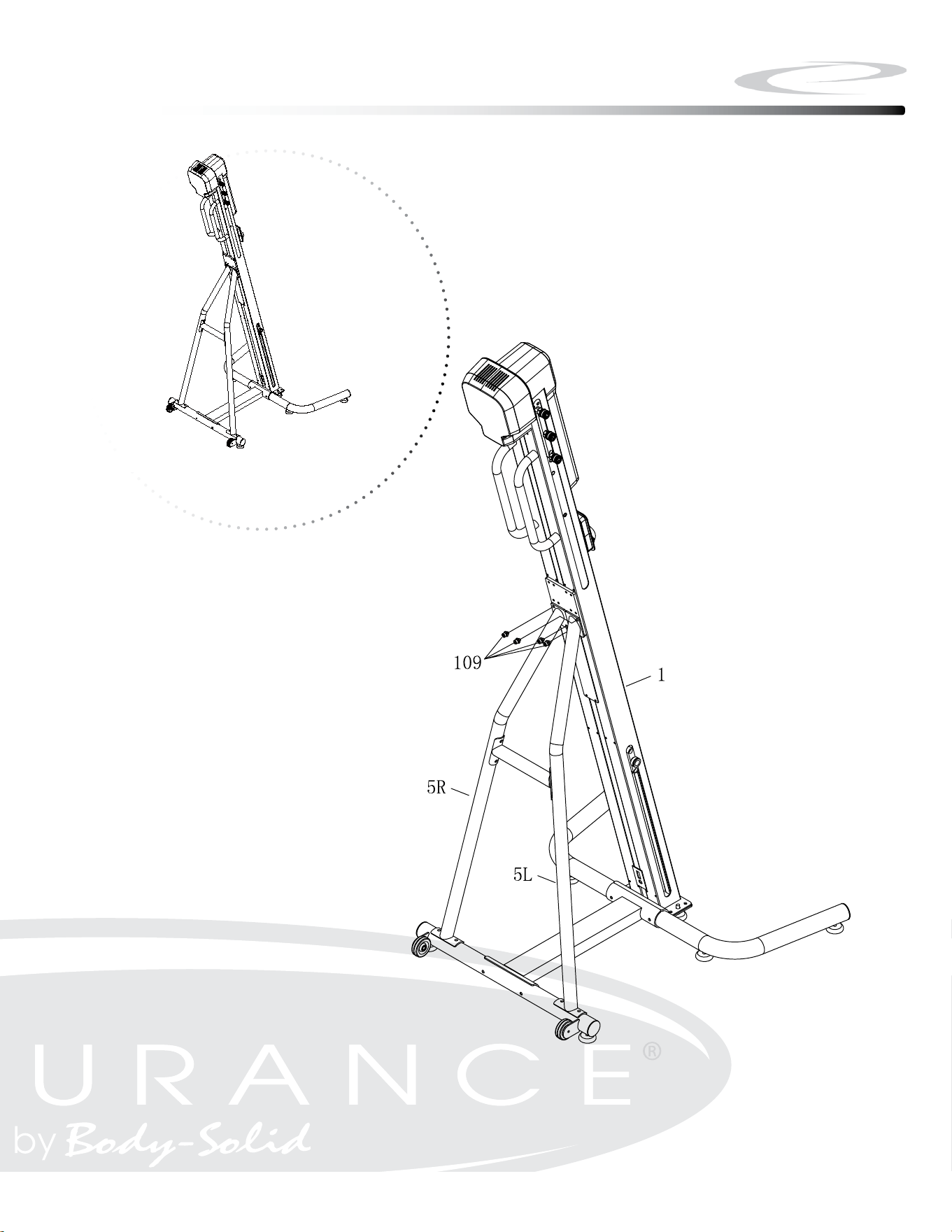
Be careful to assemble all components
in the sequence they are presented.
Note: Fully tighten bolts at the End of below Step.
4A. Attach Main Frame (#1) to Left/Right Support Tube (#5L & #5R) using:
m8x14mm socket Head Cap screw with Washers (#109), Qty: 4
Note: Please have at least two persons to hold the Main Frame (#1)
during this Step.
16
Step 4
Step 4
17
Above shows STEP 4 assembled and completed.
1
5L
5R
109

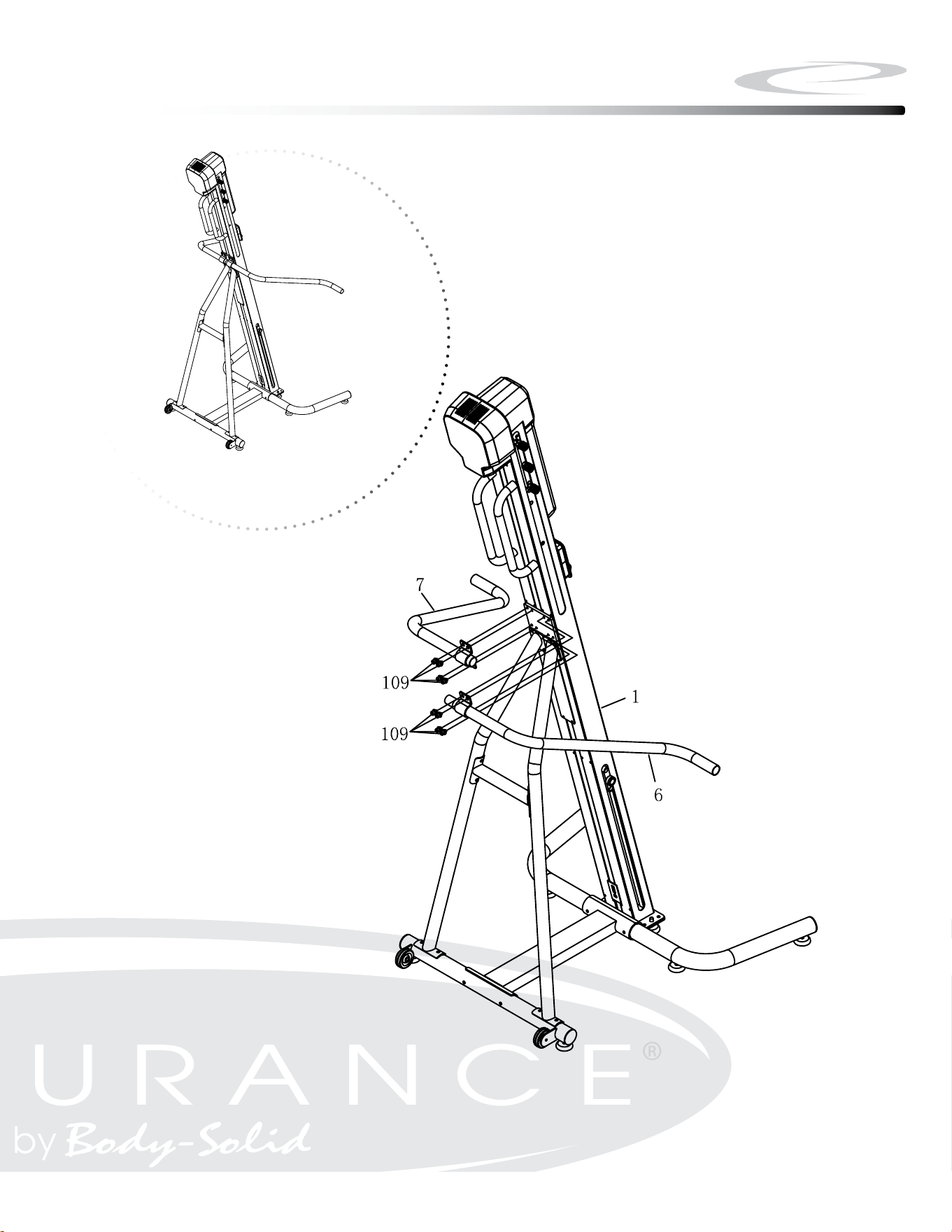
Be careful to assemble all components
in the sequence they are presented.
Note: Fully tighten bolts at the End of Step 4C.
4A. Attach Left Side Handrail (#6) to Main Frame (#1) using:
m8x14mm socket Head Cap screw with Washers (#109), Qty: 4
4B. Insert Right Side Handrail (#7) into Left Side Handrail (#6)
4C. Attach Right Side Handrail (#7) to Main Frame (#1) using:
m8x14mm socket Head Cap screw with Washers (#109), Qty: 4
18
Step 5
Step 5
19
Above shows STEP 5 assembled and completed.

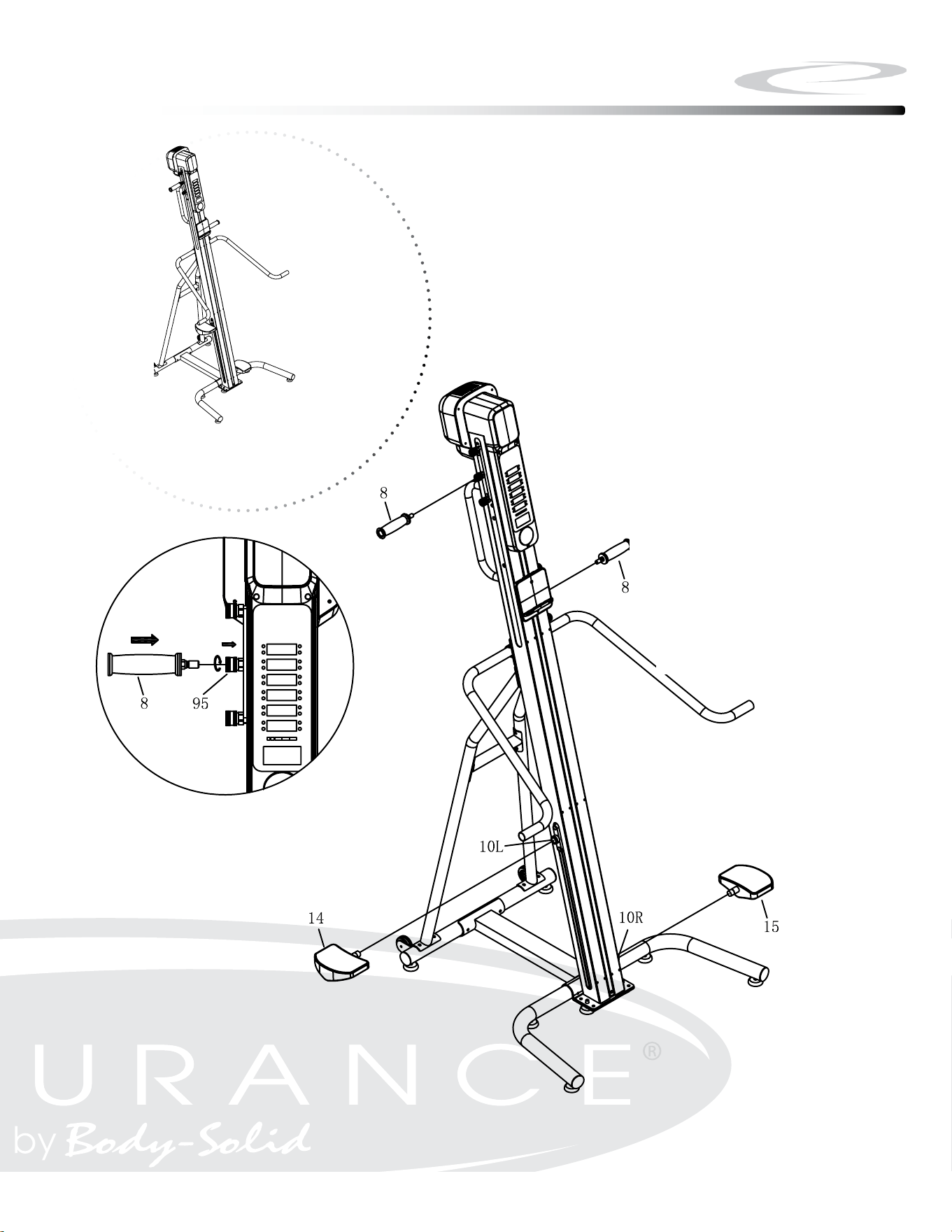
Be careful to assemble all components
in the sequence they are presented.
Note: Fully tighten bolts at the End of each Step.
6A. Press the Spring loaded Handlebar Lock (#95) inward. Insert the
Handlebar (#8)into the Spring Loaded Handlebar Lock (#95). Lock
the Handlebar (#8) in place by rotating the Spring Loaded Handlebar
Lock (#95)
6B. Attach Left / Right Foot Pedals (#14 / #15) on Left/Right Foot Pedal
Connectors (#10L / #10R)
20
Step 6
Step 6
21
Above shows STEP 6 assembled and completed.
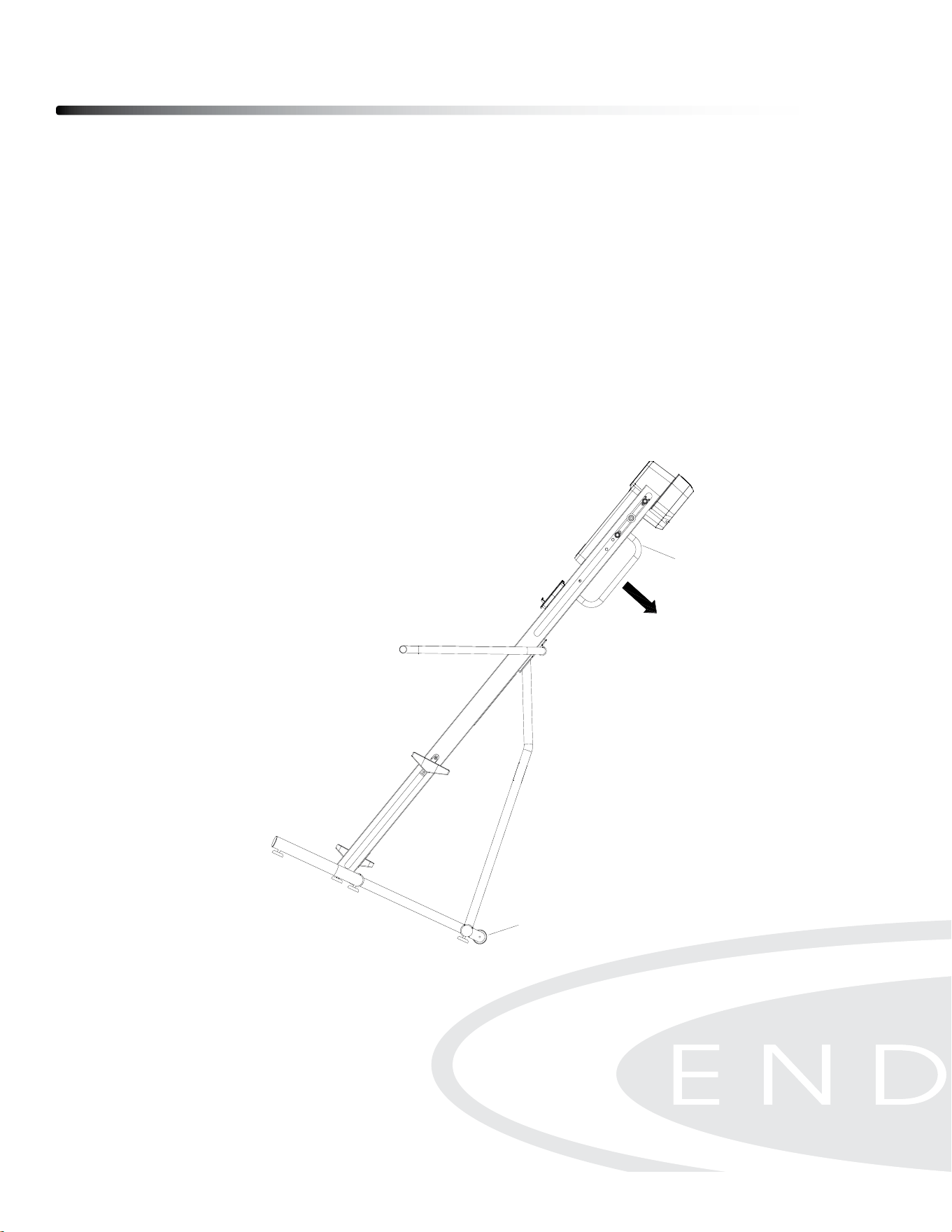
TURN POWER ON
The ON/OFF switch is located at the lower back of the Main Frame. Connect the
climber to the adapter and then connect the adapter to the electrical outlet. Filp
the switch to the “ON” position
MOVING CLIMBER
Hold the Lift Bar (1-H) with both hands on the back of the Climber and tilt the machine
at an angle. Then move the Climber with the Transport Wheels (#40)
Operating your Climber
22
ϭϲ
BEGINNER’S GUIDE
ADAPTER, PLUG-IN & SWITCH
To awake the monitor, first you need to power on the climber by using the Adapter (50) provided in the box. Plug it
into the outlet located at the lower back of the rail. Turn on the switch and you can see the light is on.
NOTE: Make sure you are using the correct type of plugs for your region.
BALANCE HANDLES
While stepping onto the climber, you may use the Balance Handles (6/7) to support yourself. It is a great tool to help
you get on and get off easily without falling.
Step onto the lower pedal and then grab the Balance Handles with both hands. Lift your body up with the support of
Balance Handles. Make sure both of your feet are completely on the pedals before beginning the exercise.
TRANSPORTATION
Hold the Lift bar (1-H) with both hands on the back of CLIMBER to tilt the CLIMBER to an angle. Then move the
CLIMBER with Transport Wheels (40) forward and backward.
1-H
40
HANDLEBAR POSITION
To change the position, unlock and remove the handle bar (#8) by pressing the Spring
Loaded Handlebar Lock (#95) inward. Choose the desired handlebar position. Press
the Spring loaded Handlebar Lock (#95) inward. Insert the Handlebar (#8)into the Spring
Loaded Handlebar Lock (#95). Lock the Handlebar (#8) in place by rotating the Spring
Loaded Handlebar Lock (#95)
HEIGHT ADJUSTMENT
The height of Foot Pad (#42) can be adjusted. First, loosen the Foot Pad Adjustment Lever
(#90) by rotating it clockwise. Then adjust the height of Foot Pad (#42) to the desired
position by turning it clockwise or counterclockwise. Finally, lock the Foot Pad Adjustment
Lever (#90) back by rotating it with counterclockwise.
Operating your Climber
23
ϭϳ
BEGINNER’S GUIDE
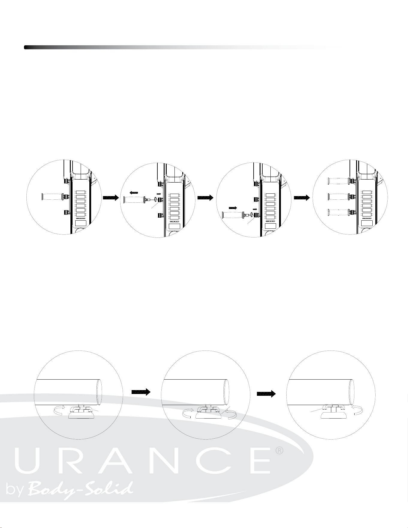
HANDLEBAR ADJUSTMENT
Our Handlebar (8) provide 3 different positions to fit with different height of people.
To change the position, unlock the Handlebar (8) by pressing the Spring Handlebar Lock (95) inward. Rotate the
Spring Handlebar Lock (95) for a few turns and hold it to remove the Handlebar (8). Confirm a different position of
the Handlebar (8), press the Spring Handlebar Lock (95) inward, and rotate it for a few turns and hold it. Insert the
Handlebar (8) into the Spring Handlebar Lock (95), and then tighten the Handlebar (8) by rotate the Spring
Handlebar Lock (95) in counter direction for a few turns.
HEIGHT ADJUSTMENT
The height of Food Pad (42) can be adjusted. Refer to the illustration. First, loosen the Foot Pad Adjustment Lever
(90) by rotating it clockwise. Then adjust the height of Foot Pad (42) to the desired position by turning it clockwise or
counterclockwise. Finally, lock the Foot Pad Adjustment Lever (90) back by rotating it with counterclockwise.
95
95
90
42
90
ϭϳ
BEGINNER’S GUIDE
HANDLEBAR ADJUSTMENT
Our Handlebar (8) provide 3 different positions to fit with different height of people.
To change the position, unlock the Handlebar (8) by pressing the Spring Handlebar Lock (95) inward. Rotate the
Spring Handlebar Lock (95) for a few turns and hold it to remove the Handlebar (8). Confirm a different position of
the Handlebar (8), press the Spring Handlebar Lock (95) inward, and rotate it for a few turns and hold it. Insert the
Handlebar (8) into the Spring Handlebar Lock (95), and then tighten the Handlebar (8) by rotate the Spring
Handlebar Lock (95) in counter direction for a few turns.
HEIGHT ADJUSTMENT
The height of Food Pad (42) can be adjusted. Refer to the illustration. First, loosen the Foot Pad Adjustment Lever
(90) by rotating it clockwise. Then adjust the height of Foot Pad (42) to the desired position by turning it clockwise or
counterclockwise. Finally, lock the Foot Pad Adjustment Lever (90) back by rotating it with counterclockwise.
95
95
90
42
90

Operating the Console
24

Operating the Console
25
CONSOLE DISPLAY
TIME:
- Workout time is accumulated under any workout mode, except for Time Countdown
Program.
- Display range: 00:00 ~ 99:59 MINUTES:SECONDS.
DISTANCE:
- Display the total height accumulated during the workout, except for Distance
Countdown Program.
- Unit displayed in feet or meter.
- Display range: 0 ~ 9999 feet or meter.
CALORIES:
- Display the total calories accumulated during the workout, except for Calories
Countdown Program.
- Display range: 0 ~ 9999 cals.
WAT T:
- Display the amount of power generated during the workout
- Display range: 0 ~ 9999 watts.
SPEED:
- Display the current exercising speed during the exercise.
- Unit displayed in feet per minute or meter per minute.
- Display range: 0.0 ~ 999.9 f/min or m/min
STEP HEIGHT:
- Display the current height of each step at any moment during the exercise.
- Unit displayed in inch or centimeter.
- Display range: 0 ~ 50 cm or 0 ~ 20 inch.
PULSE:
- Display the heart rate at any moment during the exercise. To use this function,
the user must wear a heart rate chest strap.
- Display range: 0 ~ 200 beats per minute.

RESISTANCE LEVEL
- Display resistance level on the bottom screen during exercise.
- Turn the knob clockwise or counter-clockwise to change the resistance level.
- Display range: 01-16
INITIAL SETUP
POWER ON:
- Press the “ON/OFF” switch to turn on the console
POWER OFF:
- Press the “ON/OFF” switch to turn o the console
- When there is no activity for more than 5 minutes, console will automatically enter
to sleep mode.
UNIT, WEIGHT, GENDER, AGE SETTINGS:
- User can choose between two units – metric or imperial (LED matrix displays “KM”
or “M”). During initial setup, User must nish the initial setup followed by choosing
unit, user weight, age.
- Rotate the knob to choose between options under each setting and then press the
knob to conrm the setting. Then rotate the knob again to proceed to the next setting.
- To change the setting, press the smart knob for 5 seconds in standby mode when
LED displays “P0”. When LED matrix changes to display “KM” or ”M”, then can
proceed to update the setting.
- Setting range for weight: 20 ~ 150 kg or 44 ~ 330 lbs.
- Setting range for age: 20 ~ 80 years old.
- In the standby mode (P0), press and hold for 5 seconds to go back to intial setup.
Operating the Console
26

SMART KNOB OPERATION
ROTATION:
- Rotate clockwise or counter-clockwise to choose settings, programs and values.
PRESS:
- Press the knob to conrm settings, programs or values.
- During Workout Mode, press the knob to pause the program. Press the knob again
to resume the program.
PRESS and HOLD:
- Press and hold for 3 seconds to go back to previous step while doing the setting
of any program.
- In the standby mode (P0), press and hold for 5 seconds to go to intial setup.
PROGRAMS
The console has 15 programs: Quick Start (P0), Time Countdown (TIME), Distance
Countdown (DIST), Calories Countdown (CAL), 4 Interval (I1-I4), 5 Preset Programs
(P1-P5), User Customize (USER), Heart Rate Control (HRC).
QUICK START (P0):
- Rotate the knob until the LED matrix displays “P0”
- Press Knob to start the workout program.
- Rotate Knob to change resistance level during workout.
TIME COUNTDOWN (TIME):
- Rotate the knob until the LED matrix displays “TIME”
- Press the knob to go to time setting.
- Rotate the knob to change the target time and press the knob to start the workout program.
- Rotate Knob to change resistance level during workout.
Operating the Console
27

DISTANCE COUNTDOWN (DIST):
- Rotate the knob until the LED matrix displays “DIST”
- Press the knob to go to distance setting.
- Rotate the knob to change the target distance and press the knob to start the workout
program.
- Rotate Knob to change resistance level during workout.
CALORIES COUNTDOWN (CAL):
- Rotate the knob until the LED matrix displays “DIST”
- Press the knob to go to calories setting.
- Rotate the knob to change the target calories and press the knob to start the workout
program.
- Rotate Knob to change resistance level during workout.
INTERVAL (I1):
- Rotate the knob until the LED matrix displays “I1”
- Press the knob to go to the cycle setting.
- Rotate the knob to choose the numbers of cycle and press the knob to start the workout
program.
- During the workout program, the user will exercise for 30 seconds and then rest for
30 seconds alternately until the numbers of cycle is reached. The time countdown would
not ash during exercise time and then it will ash during rest time
- LED matrix screen display the numbers of cycle left during the workout.
- Rotate Knob to change resistance level during workout.
INTERVAL (I2):
- Rotate the knob until the LED matrix displays “I2”
- Press the knob to go to the cycle setting.
- Rotate the knob to choose the numbers of cycle and press the knob to start the workout
program.
- During the workout program, the user will exercise for 45 seconds and then rest for
30 seconds alternately until the numbers of cycle is reached. The time countdown would
not ash during exercise time and then it will ash during rest time
Operating the Console
28

Operating the Console
29
- LED matrix screen display the numbers of cycle left during the workout.
- Rotate Knob to change resistance level during workout.
INTERVAL (I3):
- Rotate the knob until the LED matrix displays “I3”
- Press the knob to go to the cycle setting.
- Rotate the knob to choose the numbers of cycle and press the knob to start the workout
program.
- During the workout program, the user will exercise for 60 seconds and then rest for
30 seconds alternately until the numbers of cycle is reached. The time countdown would
not ash during exercise time and then it will ash during rest time.
- LED matrix screen display the numbers of cycle left during the workout.
- Rotate Knob to change resistance level during workout.
INTERVAL (I4):
- Rotate the knob until the LED matrix displays “I4”
- This is a customized interval program. Press and rotate the knob to enter the setting in
the following sequence: Exercise Time→Rest Time→Cycles.
- During the workout program, the user will exercise for SET seconds and then rest for
SET seconds alternately until the numbers of cycle is reached. The time countdown would
not ash during exercise time and then it will ash during rest time.
- LED matrix screen display the numbers of cycle left during the workout.
- Rotate Knob to change resistance level during workout.
PRESET PROGRAMS (P1-P5):
- Rotate the knob until the LED matrix displays “P1, P2, P3, P4 or P5”.
Press to Choose one of the Preset programs. Below table is the description of
the Preset programs.
- Rotate the knob to choose target time and press the knob to start
the workout program

USER CUSTOMIZED PROGRAM (USER):
- Rotate the knob until the LED matrix displays “USER”.
-
Press the knob to go to the target time setting.
- Rotate the knob to choose target time and press the knob to go to resistance
setting.
- Rotate the knob to choose resistance level and press the knob to conrm.
- Repeat the previous step to choose resistance levels for the remaining 15 sections.
HEART RATE CONTROL PROGRAM (HRC):
- Rotate the knob until the LED matrix displays “HRC”.
-
Press the knob to go to the Target Time setting.
- Rotate the knob to choose Target Time and press the knob to go to target heart
rate setting.
- Rotate the knob to choose Target Heart Rate (80 - 160bpm) and press the knob
to conrm.
- If Heart Rate < Target Heart Rate -5, then the resistance will increase by 1 level
every 30 seconds, up to the maximum.
- If Target Heart Rate -5 <= HR <= Target Heart Rate +5, then the resistance level
will stay the same.
- If Target Heart Rate +5 < Heart Rate, then the resistance will decrease by 1 level
every 30 seconds, up to the minimum.
- If the console doesn’t detect your Heart Rate, then the resistance level will stay
the same.
Operating the Console
30
Ϯϳ
- Time window displays the countdown time without flashing the display during exercising, but it displays
the countdown rest time with flashing during resting.
- LED matrix displays the left cycle numbers during the training.
- During the exercise, you can rotate the knob to adjust the resistance. Press the knob to pause all the
counting and view the history. Press again to resume the exercise or long-press to finish the workout.
PRESET PROGRAMS (P1-P5):
- To enter the Preset Programs, rotate the knob until LED window displays “P1/ P2/ P3/ P4/ P5”. Press
the knob to set the target time (total target training time). Rotate the knob to increase/ decrease the
target time and press the knob to confirm the setting.
- Target time is displayed at Time window.
- In the Preset Programs, Target Time will be divided equally into 16 sections. Each section will have
different preset resistance level as shown below:
Sections
Programs
Target time/16 = Time in each section
1
2
3
4
5
6
7
8
9
10 11 12 13 14 15 16
P1
Resistance
1
1
3
3
1
1
3
3
1
1
3
3
1
1
3
3
P2
Resistance
3
3
5
5
3
3
5
5
3
3
5
5
3
3
5
5
P3
Resistance
5
5
10 10
5
5
10 10
5
5
10 10
5
5
10 10
P4
Resistance
1
1
10 10
1
1
10 10
1
1
10 10
1
1
10 10
P5
Resistance
1
1
3
3
5
5
7
7
7
7
5
5
3
3
1
1
USER CUSTOMIZED PROGRAM:
- To enter the User Customized Program, rotate the knob until LED window displays “USER”. Press the
knob to complete the setting in the following sequence: Target Time→Resistance. Rotate the knob to
increase/ decrease the values and press the knob to confirm the setting. Total customized resistance is
16 sections, and please complete the setting under all sections.
- Target time is displayed at Time window, and resistance is displayed at LED matrix.
- During the exercise, you can rotate the knob to adjust the resistance. Press the knob to pause all the
counting and view the history. Press again to resume the exercise or long-press to finish the workout.
Monitoring Your Heart Rate
31
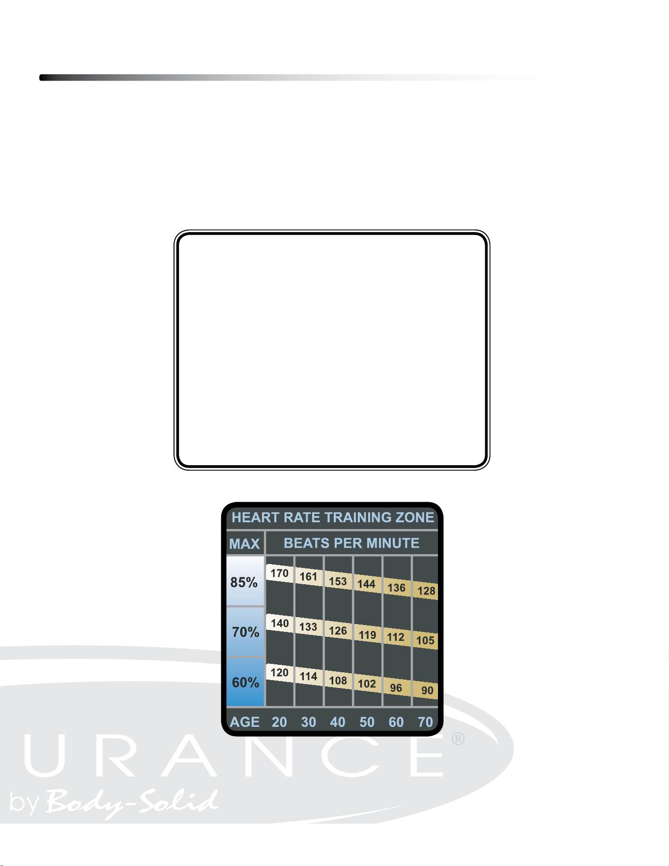
FITNESS SAFETY
The Heart Rate chart indicates average rate zones for dierent ages. A variety of dierent
factors (including medication, emotional state, temperature and other conditions) can aect
the target heart rate zone that is best for you. Your physician or health care professional can
help you determine the exercise intensity that is appropriate for your age and condition.
(MHR) = Maximum Heart Rate
(THR) = Target Heart Rate
220 - Age = Maximum Heart Rate (MHZ)
MHZ x .60 = 60% of your Maximum Heart Rate.
MHZ x .75 = 75% of your Maximum Heart Rate.
For example, if you are 30 years old, your calculations will be as follows:
220 - 30 = 190
190 x .60 = 114 (Low End or 60% of MHZ)
190 x .75 = 142 (High End or 75% of MHZ)
30 Year-Old (THR) Target Heart Rate would be 114-142
Maximum Heart Rate (MHR)
Heart Rate Training Zone

Chest Strap Operation
32
Your Endurance
®
Climber has the capability to determine Heart Rate with the use of a Heart
Rate Chest Strap. A Heart Rate Chest Strap can be purchased seperately. The frequency of
the receiver is 5KHz
It is suggested for the Chest Strap Transmitter that you position the transmitter as close to
your heart as possible, against the skin, 1-2 inches below the pectoral
muscles. For best results, moisten the back of the transmitter for better contact.
SAFETY PRECAUTIONS AND TIPS FOR CHEST STRAP
1. It is the owner’s responsibility to ensure that all users of this unit have read the Owner’s
Manual and are familiar with warnings and safety precautions.
2. Do not place chest strap near devices that generate large magnetic elds. TV sets, elec-
tric motors, radios, and high voltage power lines can aect the transmitter’s performance.
These items can interfere with the heart rate signal and possibly aect the heart rate
readings on the console.
3. Handle the Chest Strap with care. Dropping the transmitter might cause damage that
could void the warranty.
4. Do not use the chest strap if you have a cardiac pacemaker or if your are taking medica-
tions for a heart condition. Medication or electrical pulses from the pacemaker can inter-
fere with accurate heart rate readings.
5. Do not bend the strips inside the chest strap. This can cause the chest strap to loose
conductivity.
6. The chest strap has batteries that need to be replaced periodically. A faulty battery can
cause inaccurate reading.
Maintenance
33
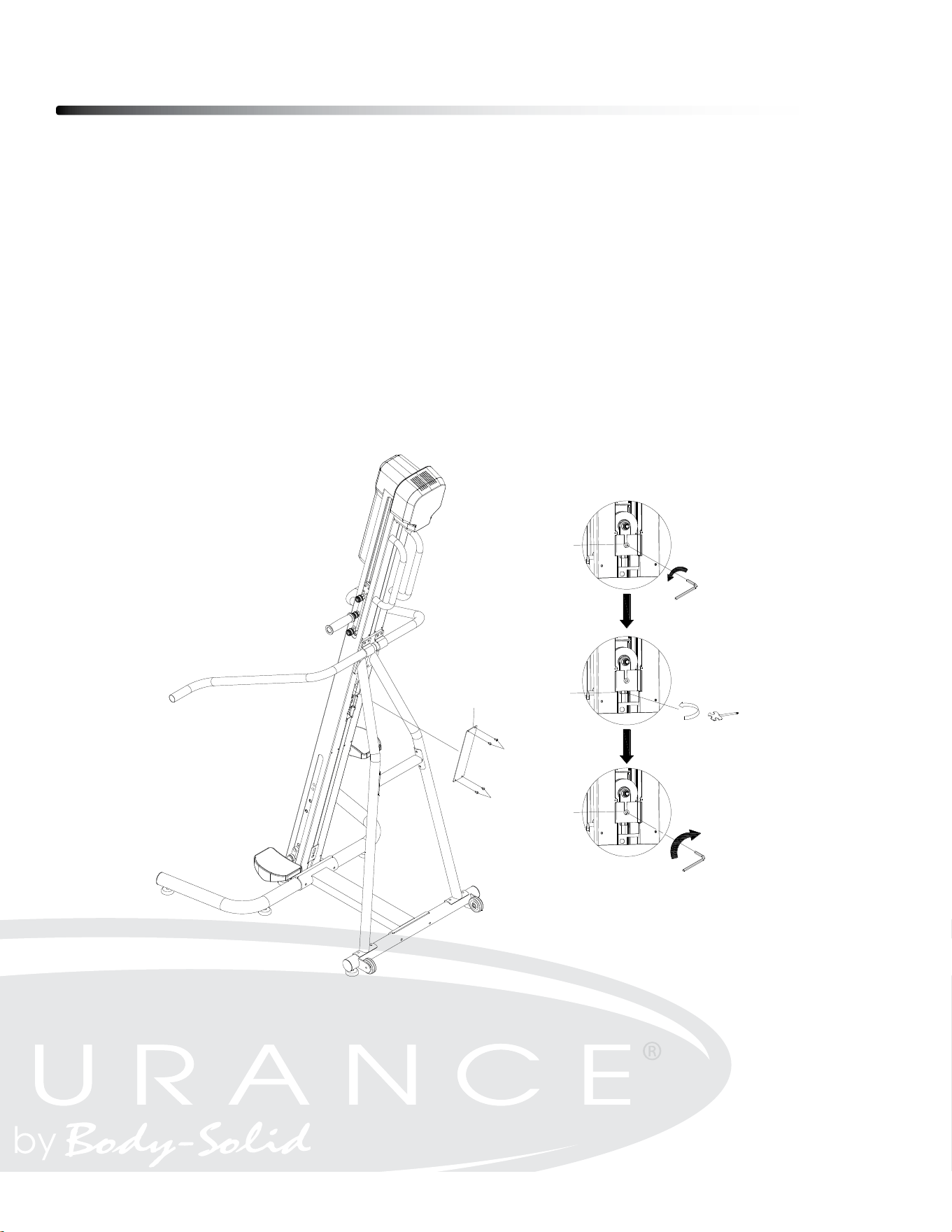
CABLE ADJUSTMENT
Over time, the cable may get looser. Please follow the guideline for adjustment.
1. Remove the Back Cover (20) and loosen the Flat Socket Head Cap Screw, M8x22
(115) by using Allen Wrench.
2. Adjust the Hex Nut M10 (79) to the desired tightness by using Open End Wrench
13-15-17mm (91).
3. Then tighten the Flat Socket Head Cap Screw, M8x22 (115).
4. Attach the Back Cover (20) to Main Frame (1) by using Button Head Cap Screw
M5x8mm (59).
ϮϬ
MAINTENANCE
The safety and integrity designed into the CLIMBER can only be maintained when the CLIMBER is regularly
examined for damage and wear. Special attention should be given to the following:
CABLE ADJUSTMENT
Over time, the cable may get loosen. Please follow the guideline for adjustment.
1. Remove the Back Cover (20) and loosen the Flat Socket Head Cap Screw, M8x22 (115) by using Allen Wrench.
2. Adjust the Hex Nut M10 (79) to the desired tightness by using Open End Wrench 13-15-17mm (91).
3. Then tighten the Flat Socket Head Cap Screw, M8x22 (115).
4. Attach the Back Cover (20) to Main Frame (1) by using Button Head Cap Screw M5x8mm (59).
TO PREVENT SEVERE INJURIES AND MAINTAIN HEALTHY CONDITION, PLEASE
CAREFULLY EVALUATE PERSONAL CAPABILITY AND MONITOR THE HEART RATE
CONSTANTLY. STOP IMMEDIATELY IF YOU FEEL ANY KIND OF DISCOMFORT AND
CONSULT FOR PHYSICAL ADVICE FROM PROFESSIONALS.
59
20
59
115
79
115

Maintenance
34
MAGNETIC BRAKE VALUE SETTING ADJUSTMENT
- Resistance force level can be changed by changing the magnetic brake value
- In the standby mode (P0), Press the Knob and hold it for 10 seconds. LED screen
will display the default setting of the magnetic brake value. Rotate the knob to increase/
decrease the value with range from 30 - 50. Press the knob to conrm the value with LED
displaying “OK”. The factory preset value is 40.

Part numbers are required when ordering parts.
Parts List
35
31
PART# DESCRIPTION QTY
1 Main Frame 1
2 Front Stabilizer 1
3 Rear Stabilizer 1
4 Base Connection Tube 1
5L Left Support Tube 1
5R Right Support Tube 1
6 Left Side Handrail 1
7 Right Side Handrail 1
8 Handlebar 2
9L Left Traveling Bracket 1
9R Right Traveling Bracket 1
10L Left Foot Pedal Connector 1
10R Right Foot Pedal Connector 1
11 Handlebar Adjustment Base 2
12 Motor Bracket 1
13 Cable Adjustment Bracket 1
14 Left Foot Pedal 1
15 Right Foot Pedal 1
16 Belt Fixation Bracket 2
17 Speed Sensor Counter 1
18 Bearing Spacer 2
19 Front Cover 1
20 Back Cover 1
22 Braking System Motor 1
23 Aluminum Alloy Pulley 1
24 Bearing 6000 33
25 C Ring Φ26 1
26 Roller Guide Rail 4
27 Roller 16
28 Base of Bearing 6004 1
29 Bearing 6004 1
32 Belt Pulley Axis 1
33 Belt Pulley 1
34 Belt 1
Part# DesCriPtion Qty
ø20x ø14x ø10x 15mm

Parts List
36
Part# DesCriPtion Qty
31
PART# DESCRIPTION QTY
1 Main Frame 1
2 Front Stabilizer 1
3 Rear Stabilizer 1
4 Base Connection Tube 1
5L Left Support Tube 1
5R Right Support Tube 1
6 Left Side Handrail 1
7 Right Side Handrail 1
8 Handlebar 2
9L Left Traveling Bracket 1
9R Right Traveling Bracket 1
10L Left Foot Pedal Connector 1
10R Right Foot Pedal Connector 1
11 Handlebar Adjustment Base 2
12 Motor Bracket 1
13 Cable Adjustment Bracket 1
14 Left Foot Pedal 1
15 Right Foot Pedal 1
16 Belt Fixation Bracket 2
17 Speed Sensor Counter 1
18 Bearing Spacer 2
19 Front Cover 1
20 Back Cover 1
22 Braking System Motor 1
23 Aluminum Alloy Pulley 1
24 Bearing 6000 33
25 C Ring Φ26 1
26 Roller Guide Rail 4
27 Roller 16
28 Base of Bearing 6004 1
29 Bearing 6004 1
32 Belt Pulley Axis 1
33 Belt Pulley 1
34 Belt 1
32
35 Console Monitor Front Cover 1
36 Console Monitor Back Cover 1
37 Tablet Holder 1
38 Tablet Holder Base 1
40 Transport Wheel 2
42 Stabilizer Foot Pad 8
43 Cushion 2
44 Cable 1
47 Power Switch 1
48 Power Cord 1
49 LED Control Knob 1
50 Adaptor 1
51 Fan 1
52 Speed Sensor 1
54 DC Power Cable 1
56 Phillips Pan Head Self-Tapping Screw, ST4.2x16mm 4
57 Phillips Pan Head Screw, M4x30mm 4
59 Button Head Cap Screw, M5x8mm 37
60 Button Head Cap Screw, M6x8mm 27
61 Flat Washer M6 22
62 Socket Head Cap Screw, M4x20mm 8
66 Button Head Cap Screw, M6x12mm 8
67 Socket Head Cap Screw, M6x16mm 6
68 Spring Washer M6 6
69 Socket Head Cap Screw, M8x10mm 8
72 Socket Head Cap Screw, M8x40mm 2
73 Flat Washer M8 4
74 Nylon Nut M8 4
75 Button Head Cap Screw, M10x45mm 1
76 Flat Washer M10 1
77 Nylon Nut M10 1
78 Socket Head Cap Screw, M8x15mm 2
79 Hex Nut M10 1
80 C Ring Φ20 2
81 Phillips Flat Head Screw, M5 x 30mm 2
D8M15-760mm
M6x
ø26x 36mm
Power Supply (Input 100-240V AC, Output 24V DC)
ø41.5x ø35.5x ø21x 28.5mm

Part numbers are required when ordering parts.
Parts List
37
Part# DesCriPtion Qty
32
35 Console Monitor Front Cover 1
36 Console Monitor Back Cover 1
37 Tablet Holder 1
38 Tablet Holder Base 1
40 Transport Wheel 2
42 Stabilizer Foot Pad 8
43 Cushion 2
44 Cable 1
47 Power Switch 1
48 Power Cord 1
49 LED Control Knob 1
50 Adaptor 1
51 Fan 1
52 Speed Sensor 1
54 DC Power Cable 1
56 Phillips Pan Head Self-Tapping Screw, ST4.2x16mm 4
57 Phillips Pan Head Screw, M4x30mm 4
59 Button Head Cap Screw, M5x8mm 37
60 Button Head Cap Screw, M6x8mm 27
61 Flat Washer M6 22
62 Socket Head Cap Screw, M4x20mm 8
66 Button Head Cap Screw, M6x12mm 8
67 Socket Head Cap Screw, M6x16mm 6
68 Spring Washer M6 6
69 Socket Head Cap Screw, M8x10mm 8
72 Socket Head Cap Screw, M8x40mm 2
73 Flat Washer M8 4
74 Nylon Nut M8 4
75 Button Head Cap Screw, M10x45mm 1
76 Flat Washer M10 1
77 Nylon Nut M10 1
78 Socket Head Cap Screw, M8x15mm 2
79 Hex Nut M10 1
80 C Ring Φ20 2
81 Phillips Flat Head Screw, M5 x 30mm 2
ϯϮ
78 Socket Head Cap Screw, M8x15mm 2
79 Hex Nut M10 1
80 C Ring Φ20 2
81 Phillips Flat Head Screw, M5 x 30mm 2
82 Upper Tablet Holder Hook 1
83 Bungee Cord 1
84 EVA Pad (Upper Tablet Holder Hook) 1
85 EVA Pad (Tablet Holder Base) 1
88 Allen Wrench 6mm 1
89 Allen Wrench 4mm 1
90 Foot Pad Adjustment Lever 6
91 Open End Wrench 13-15-17mm 1
92 Roller Protector 2
93 Long Parallel Key 1
94 Short Parallel Key 1
95 Spring Handlebar Lock 6
96 Spring Handlebar Lock Axis 2
97 Handlebar Sleeve 2
99 LED Console 1
100
Nylon Spacer
2
101
Socket Head Cap Screw, M5x37mm
2
102
Socket Head Cap Screw, M5x45mm
1
103
Socket Head Cap Screw, M5x10mm
4
104
Flat Washer 16*6.2*1.5T
1
105
Socket Head Cap Screw, M8x70mm
4
106
Lock Washer M8
4
107
Arc Washer M8
6
108
Support Connection Tube
1
109
Pre-assembled Socket Head Cap Screw, M8x14mm (include Spring Washer
& Flat Washer)
24
110
Adjustment Spacer Φ12*Φ8.2*11
1
111
Flat Washer Φ38*Φ12*3
2
112
Counterbored Washer
2
113
Star Nut (Double Layer) M6*10
2
ø4x 350mm
Handlebar Grip

Parts List
38
ϯϮ
78
Socket Head Cap Screw, M8x15mm
2
79
Hex Nut M10
1
80
C Ring Φ20
2
81
Phillips Flat Head Screw, M5 x 30mm
2
82
Upper Tablet Holder Hook
1
83
Bungee Cord
1
84
EVA Pad (Upper Tablet Holder Hook)
1
85
EVA Pad (Tablet Holder Base)
1
88
Allen Wrench 6mm
1
89
Allen Wrench 4mm
1
90
Foot Pad Adjustment Lever
6
91
Open End Wrench 13-15-17mm
1
92
Roller Protector
2
93
Long Parallel Key
1
94
Short Parallel Key
1
95
Spring Handlebar Lock
6
96
Spring Handlebar Lock Axis
2
97
Handlebar Sleeve
2
99
LED Console
1
100 Nylon Spacer 2
101 Socket Head Cap Screw, M5x37mm 2
102 Socket Head Cap Screw, M5x45mm 1
103 Socket Head Cap Screw, M5x10mm 4
104 Flat Washer 16*6.2*1.5T 1
105 Socket Head Cap Screw, M8x70mm 4
106 Lock Washer M8 4
107 Arc Washer M8 6
108 Support Connection Tube 1
109 Pre-assembled Socket Head Cap Screw, M8x14mm (include Spring Washer
& Flat Washer)
24
110
Adjustment Spacer Φ12*Φ8.2*11
1
111 Flat Washer Φ38*Φ12*3 2
112 Counterbored Washer 2
113 Star Nut (Double Layer) M6*10 2
ϯϯ
114 Hex Head Cap Screw, M6x12 2
115 Flat Socket Head Cap Screw, M8x22 1
116 C Ring Φ25 1
Socket Head Cap Screw, M8x14mm
(with Spring Washer & Flat Washer)
ø9x ø5x 6mm
Part# DesCriPtion Qty
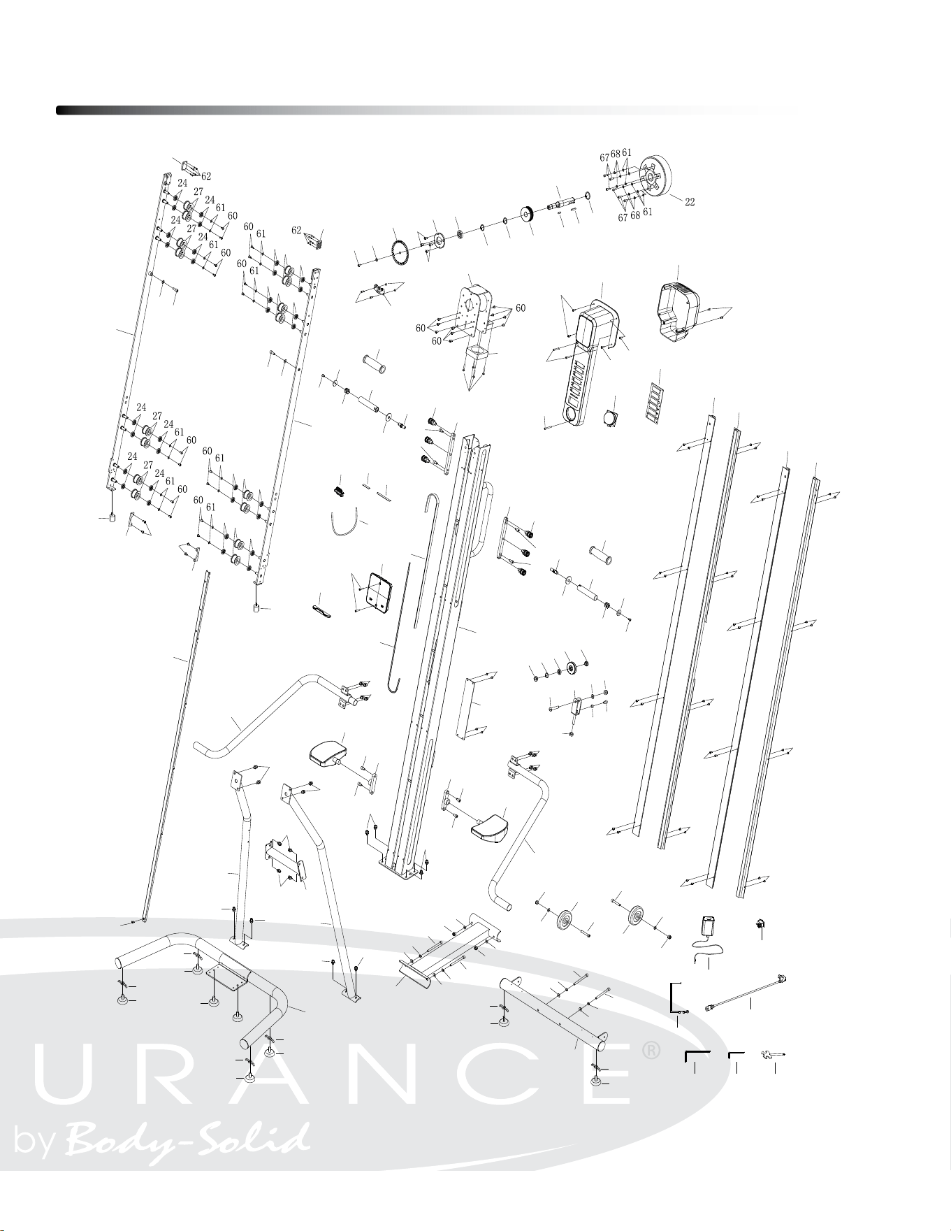
Exploded View Diagram
39
Ϯϵ
PRODUCT PARTS DRAWING
1
2
3
9R
9L
10R
10L
8
8
6
7
16
16
11
11
4
19
20
90
90
90
14
15
17
28
29
33
52
60
104
66
66
32
80
23
24
25
18
18
26
59
59
59
59
26
59
59
59
59
26
59
59
59
59
26
59
59
59
59
24
27
24
24
27
24
24
27
24
24
27
24
66
66
92
92
34
94
93
95
95
96
96
12
51
57
36
35
38
37
81
82
83
84
85
40
40
74
72
73
72
73
74
42
42
42
42
43
43
44
97
97
47
48
50
88
89
91
54
49
99
56
56
56
100
101
102
103
103
59
59
59
69
69
69
69
69
69
69
69
109
73
78
73
78
79
75
76
77
13
115
80
105
106
107
105
106
107
105
106
107
105
106
107
90
42
90
42
90
42
5L
5R
108
109
109
109
109
109
109
109
109
109
109
109
109
109
107
107
74
74
110
111
111
112
112
113
113
114
114
116
c
Copyright 2009. Body-Solid. All rights reserved. Body-Solid reserves the right to change design and specications when we feel it will improve the product.
Body-Solid machines maintain several patented and patent pending features and designs. All rights reserved on all design patents and utility patents.
Customer Tech Support Hotline
Toll Free: 1-800-556-3113
Phone: 1-708-427-3555
Fax: 1-708-427-3556
Hours: M-F 8:30-5:00 CST
E-Mail: ser[email protected]om
Serial Number is Located on the Frame
Model Name
:
CL300
Purchase Date
: _______________________________
Serial Number
: 017979-_______________________