owner’s manual
v. 063010
INDOOR EXERCISE BIKE
USER MANUAL
HP-SP0908 (Home Use)
2
Table of conTenTs
I. Before You BegIn...........................................
II. IMPorTAnT SAfeTY InSTruCTIonS...............
III. feATureS.............................................................
IV. dIMenSIonS.........................................................
V. ASSeMBlY InSTruCTIonS................................
VI. SeTTIng uP Your BfSB5.................................
VII. eXerCISe TIPS And guIdelIneS.....................
VIII. BrAKe PAd rePlACeMenT...............................
IX. BrAKe KnoB rePlACeMenT............................
X. ChAIn rePlACeMenT........................................
XI. SerVICIng The BfSB5......................................
XII. hArdWAre...........................................................
XIII. hArdWAre lIST.................................................
XIV. eXPloded VIeW dIAgrAM...............................
3
4
5
6
7 – 19
20 – 21
22 – 23
24 – 25
26 – 27
28 – 29
30
31
32 – 34
35
www.BestFitness.com

3
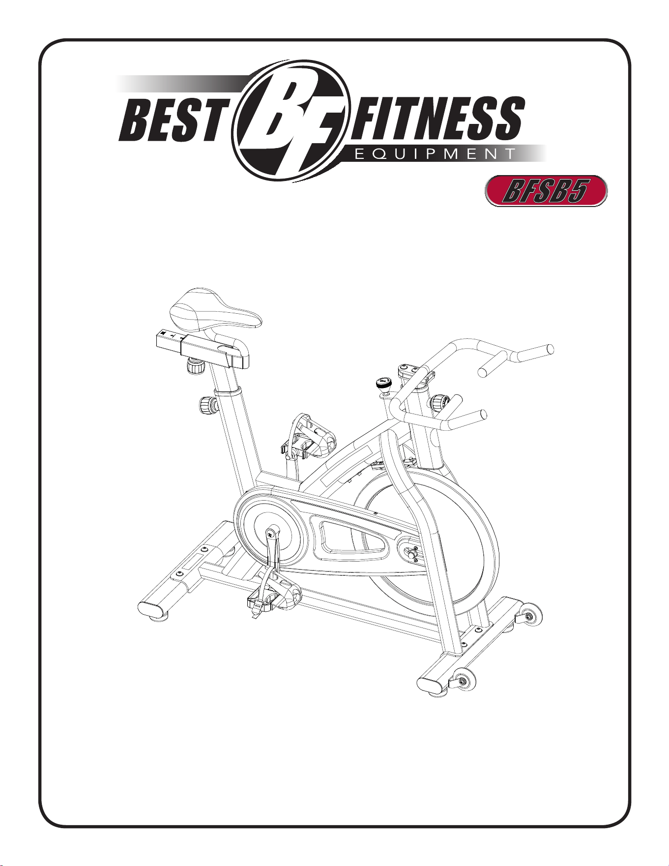
Thank you for purchasing the Best fitness Spin Bike BfSB5.
To maximize your use of the equipment please study this owner’s Manual thoroughly.
Unpacking the eqUipment
The BfSB5 is carefully tested and inspected before shipment. We have shipped the unit
in several pieces that require assembly. Ask for assistance during the assembly process.
caUtion
■ Cut the box open on all four ends.
■ remove any loose paCking material and Components.
■ hold the unit on eaCh side and lift it out from the box
Carefully.
■ read the owner’s manual thoroughly before attempting to
assemble the unit.
before You begin
Best fitness equipment continually seeks ways to improve the performance, specifications and product manuals in order to ensure
that only superior products are released from our factories. Please take the time to carefully read through this manual thoroughly.
Instructions contained in this document are not intended to cover all details or variations possible with Best fitness equipment, or to
cover every contingency that may be met in conjunction with installation, operation, maintenance or troubleshooting of the equipment.
even though we have prepared this manual with extreme care, neither the publisher nor the author can accept responsibility for any
errors in, or omission from, the information given. Should additional information be required, or should situations arise that are not
covered by this manual, the matter should be directed to your local Best fitness equipment representative, or the Service department
at Best fitness equipment in forest Park, Illinois.
Any Questions?
Call (800) 556-3113

4
imporTanT safeTY insTrucTions
before beginning any fitness program, you should obtain a complete physical
examination from your physician.
Il est conseille de subir un examen medical complet avant d’entreprendre tout programme d’exercise. Si vous avez des
etourdissements ou des faiblesses, arretez les exercices immediatement.
Antes de comenzar cualquier programma de ejercicios, deberias tener un examen fisico con su doctor.
When Using exercise eqUipment, yoU shoUld alWays take basic
precaUtions, inclUding the folloWing:
read all instructions before using the BfSB5. These instructions are written to ensure your
safety and to protect the unit.
do not allow children on or near the equipment.
use the equipment only for its intended purpose as described in this guide. do not use ac-
cessory attachments that are not recommended by the manufacturer. Such attachments
might cause injuries.
Wear proper exercise clothing and shoes for your workout, no loose clothing.
use care when getting on or off the unit.
do not overexert yourself or work to exhaustion.
If you feel any pain or abnormal symptoms, stop your workout immediately and consult your
physician.
never operate the unit when it has been dropped or damaged. return the equipment to a
service center for examination and repair.
never drop or insert objects into any opening in the equipment.
Always check the unit before each use. Make sure that all fasteners are secure and in good
working condition.
do not use the equipment outdoors or near water.
personal safety dUring assembly
It is strongly recommended that a qualified dealer assemble the equipment. Assistance is
required.
Before beginning assembly, please take the time to read the instructions thoroughly.
read each step in the assembly instructions and follow the steps in sequence. do not skip
ahead. If you skip ahead, you may learn later that you have to disassemble components and
that you may have damaged the equipment.
Assemble and operate the BfSB5 on a solid, level surface. locate the unit a few feet from
the walls or furniture to provide easy access.
The BfSB5 is designed for your enjoyment. By following these precautions and using common
sense, you will have many safe and pleasurable hours of healthful exercise with your Best fit-
ness BfSB5.
After assembly, you should check all functions to ensure correct operation. If you experience
problems, first recheck the assembly instructions to locate any possible errors made during as-
sembly. If you are unable to correct the problem, call the dealer from whom you purchased the
machine or call 1-800-556-3113 for the dealer nearest you.
•
•
•
•
•
•
•
•
•
•
•
•
•
•
•
5
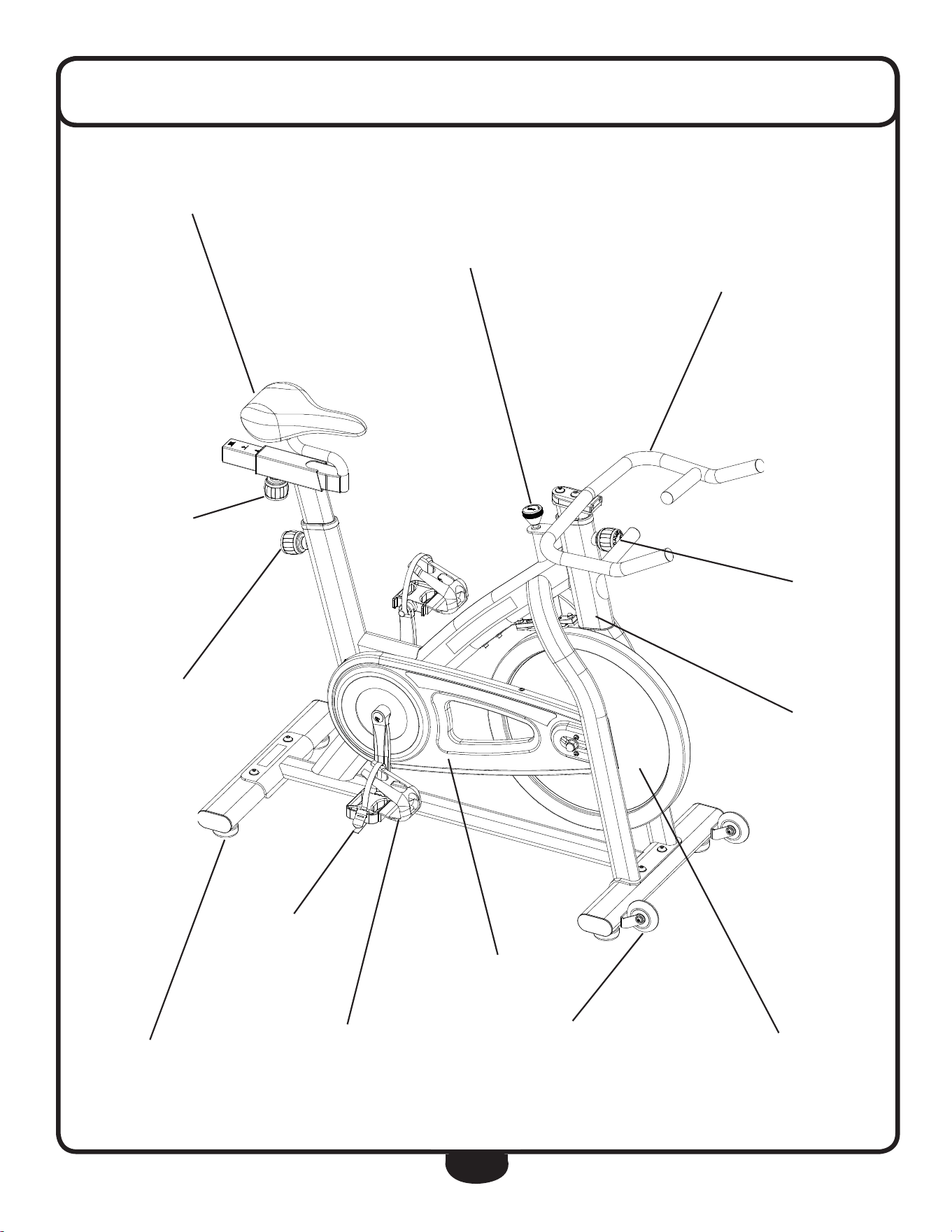
feaTures
INDOOR EXERCISE BIKE
USER MANUAL
HP-SP0908 (Home Use)
Tension
AdjusTmenT/
emergency sTop
shroud
pedALs
ergonomic
hAndLe BArs
LeveL
sTABiLizer
TrAnsporT
WheeLs
exTrA sofT seAT
horizonTAL
seAT
AdjusTmenT
verTicAL
seAT
AdjusTmenT
verTicAL
hAndLe BAr
AdjusTmenT
coWhide
LeATher
BrAKe pAd
fLyWheeL
AdjusTABLe
fooT sTrAps
INDOOR EXERCISE BIKE
USER MANUAL
HP-SP0908 (Home Use)
6
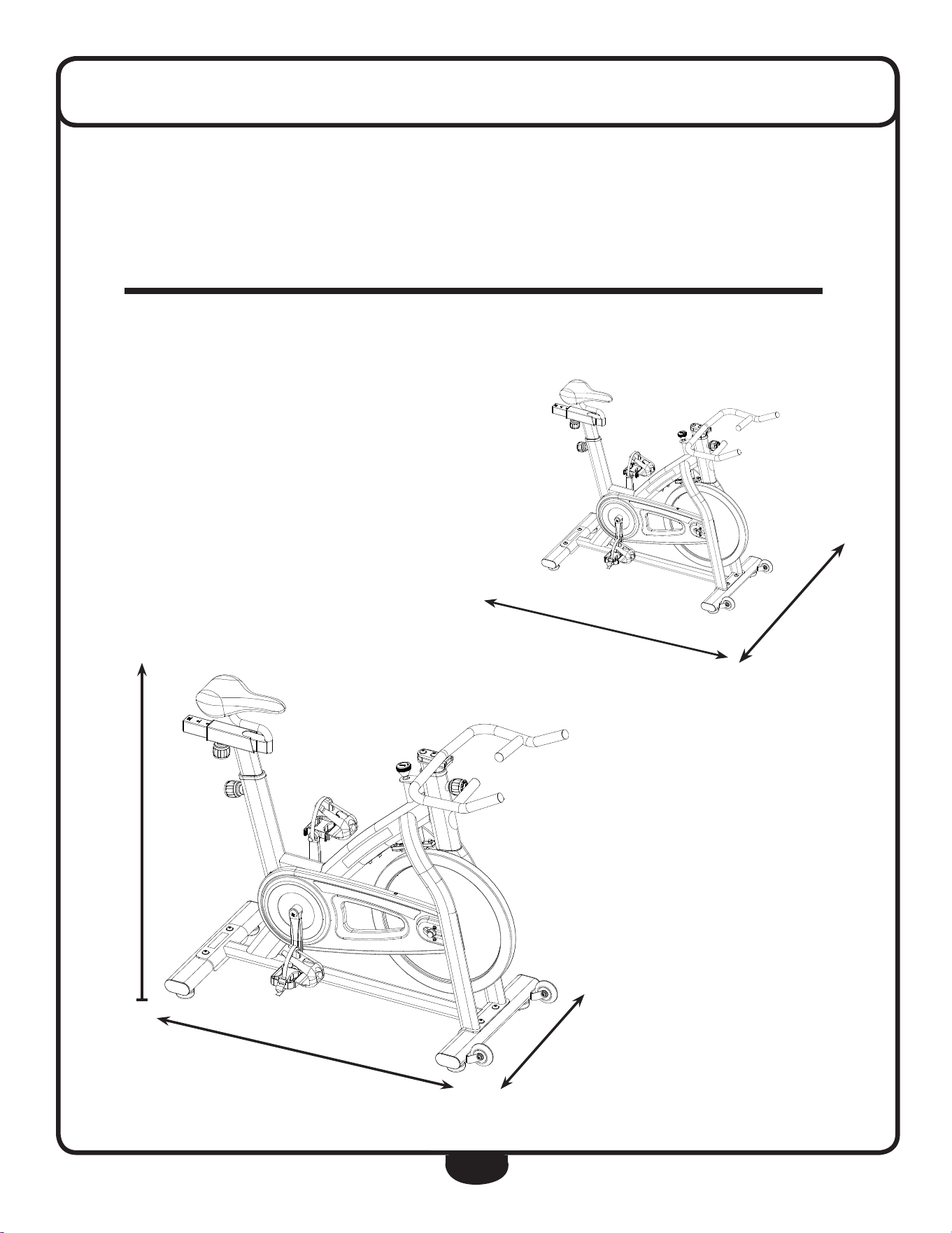
dimensions
3’ 8”
3’ 7”
1’ 9”
The room layout diagram below will help you decide the best placement for your BfSB5.
The dimensions of the BfSB5 are: Width 1’ 9” X length 3’ 7”.
The usage space is: Width 3’ X length 6’ (The usage space is the overall space needed for
operation).
The usage space needed for the BfSB5 could be more, depending on the user.
Minimum Usage Space
Suggested Usage Space
3’
6’
INDOOR EXERCISE BIKE
USER MANUAL
HP-SP0908 (Home Use)
7
Assembly of the BfSB5 takes professional installers about 1/2 hour to complete. If this is
the first time you have assembled this type of equipment, plan on significantly more time.
Professional installers are highly recommended!
however, if you acquire the appropriate tools, obtain assistance, and follow the assembly
steps sequentially, the process will take time, but is fairly easy.
assembly tips
read all “notes” on each page before begin-
ning each step.
While you may be able to assemble the BfSB5
using the illustrations only, important safety
notes and other tips are included in the text.
Some pieces may have extra holes that you
will not use. use only those holes indicated in
the instructions and illustrations.
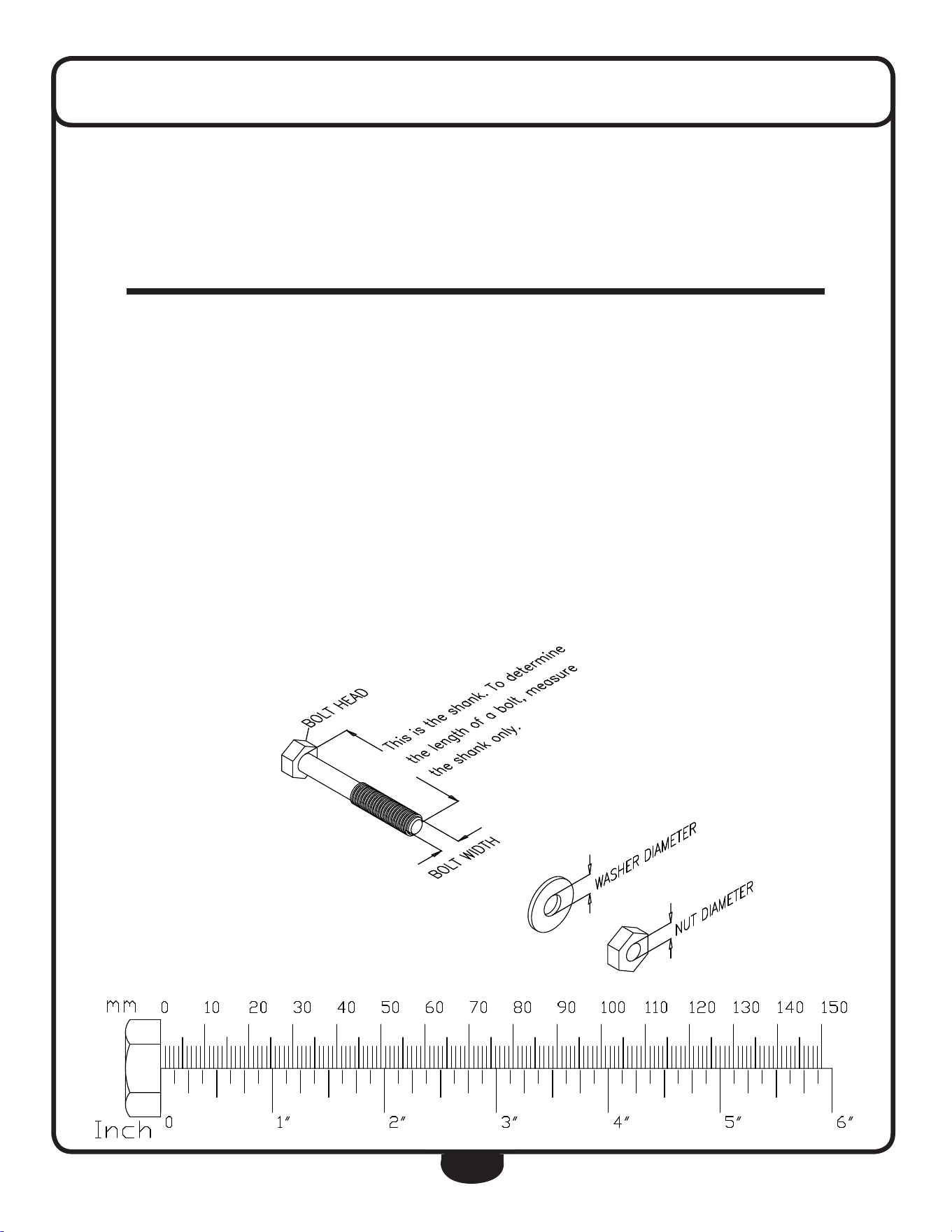
noTe: To find out the length of a particular
bolt, measure its shank (the long, narrow part
beneath the head).
refer to the following diagram:
noTe: After assembly, you should check all
functions to ensure correct operation. If you
experience problems, first recheck the assem-
bly instructions to locate any possible errors
made during assembly.
If you are unable to correct the problem, call
the dealer from whom you purchased the ma-
chine or call 1-800-556-3113 for the dealer
nearest you.
assemblY insTrucTions

8
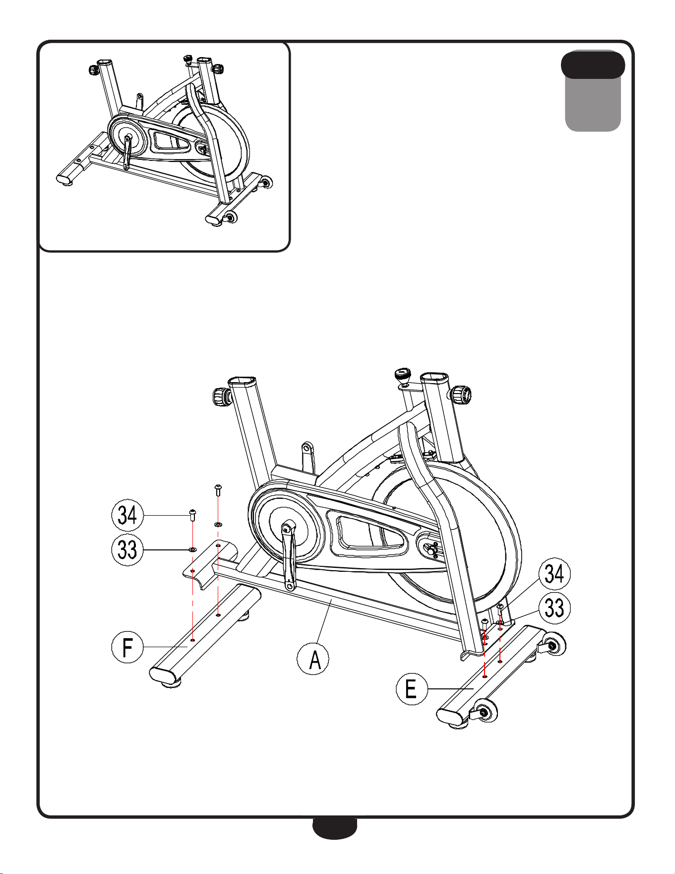
be careful to assemble all components
in the sequence they are presented.
noTe: chrome hardware is used in this step.
A. Connect rear Base (f) to Main frame (A) using:
two 34 (m10 round allen head bolt)
two 33 (m10 washer)
B. Connect front Base (e) to Main frame (A) using:
two 34 (m10 round allen head bolt)
two 33 (m10 washer)
s T e p
1
9
s T e p
1
Above shows STeP 1 assembled and completed.
10
Step 2: Install Left Pedal and Right one.
Refer to the figure below, insert the Left Pedal and Right One (30) into the Crank (28) & (29) with
Opening Wrench #15.
10
Step 2: Install Left Pedal and Right one.
Refer to the figure below, screw the Right Pedal (30) into the Right Crank (28) by hand (clockwise), and
screw the Left Pedal into the Left Crank (29) by hand (counter-clockwise), then use the Opening Wrench
#15 to lock up. (Note:both of the screw direction is heading for handlebar.)

10
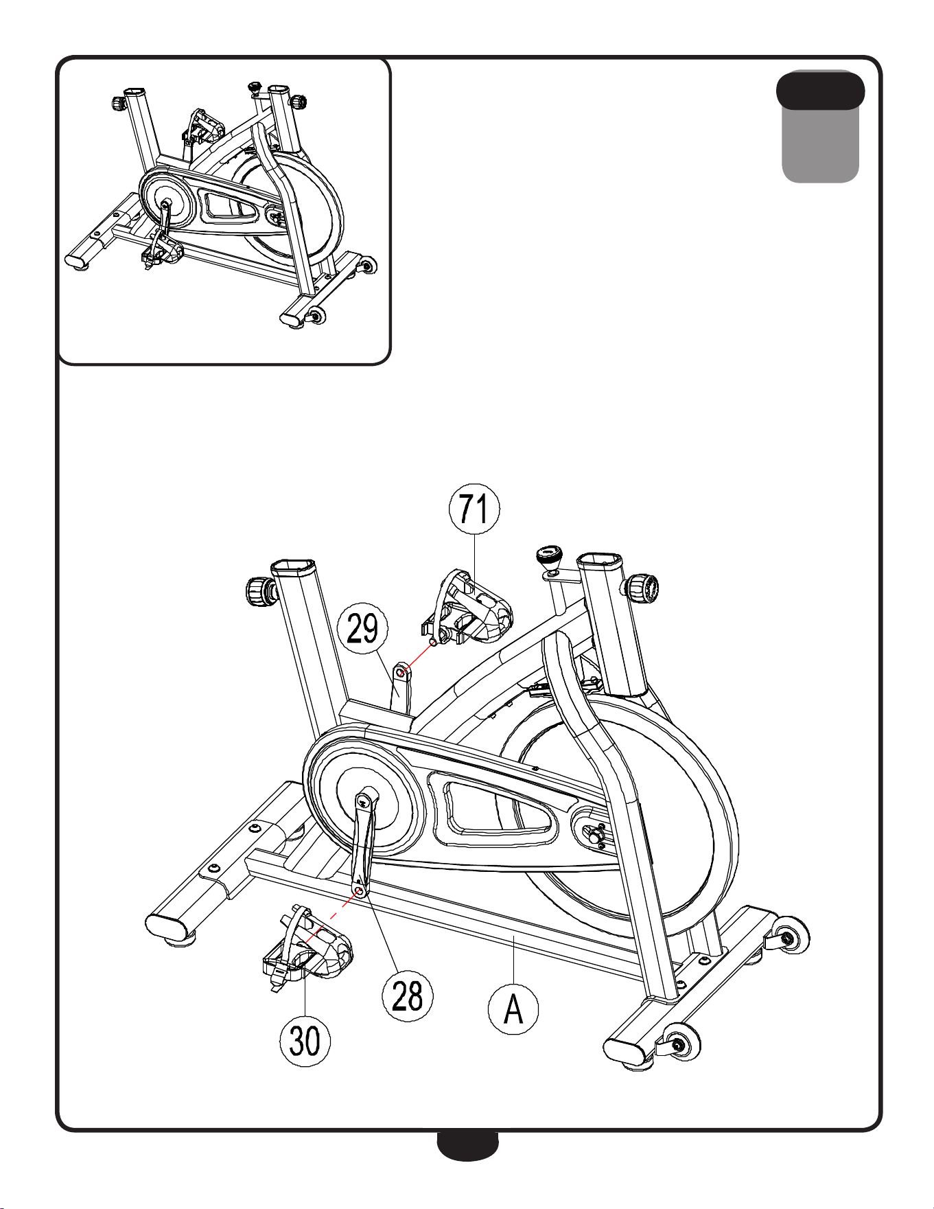
be careful to assemble all components
in the sequence they are presented.
A. Connect right Pedal (30) to right Crank (28) by threading right Pedal (30)
with the wrench provided.
noTe: Wrench right Pedal (30) clockwise.
B. Connect left Pedal (71) to left Crank (29) by threading left Pedal (71)
with the wrench provided.
noTe: Wrench left Pedal (71) counter-clockwise.
s T e p
2
11
s T e p
2
Above shows STeP 2 assembled and completed.
10
Step 2: Install Left Pedal and Right one.
Refer to the figure below, insert the Left Pedal and Right One (30) into the Crank (28) & (29) with
Opening Wrench #15.
10
Step 2: Install Left Pedal and Right one.
Refer to the figure below, screw the Right Pedal (30) into the Right Crank (28) by hand (clockwise), and
screw the Left Pedal into the Left Crank (29) by hand (counter-clockwise), then use the Opening Wrench
#15 to lock up. (Note:both of the screw direction is heading for handlebar.)

12
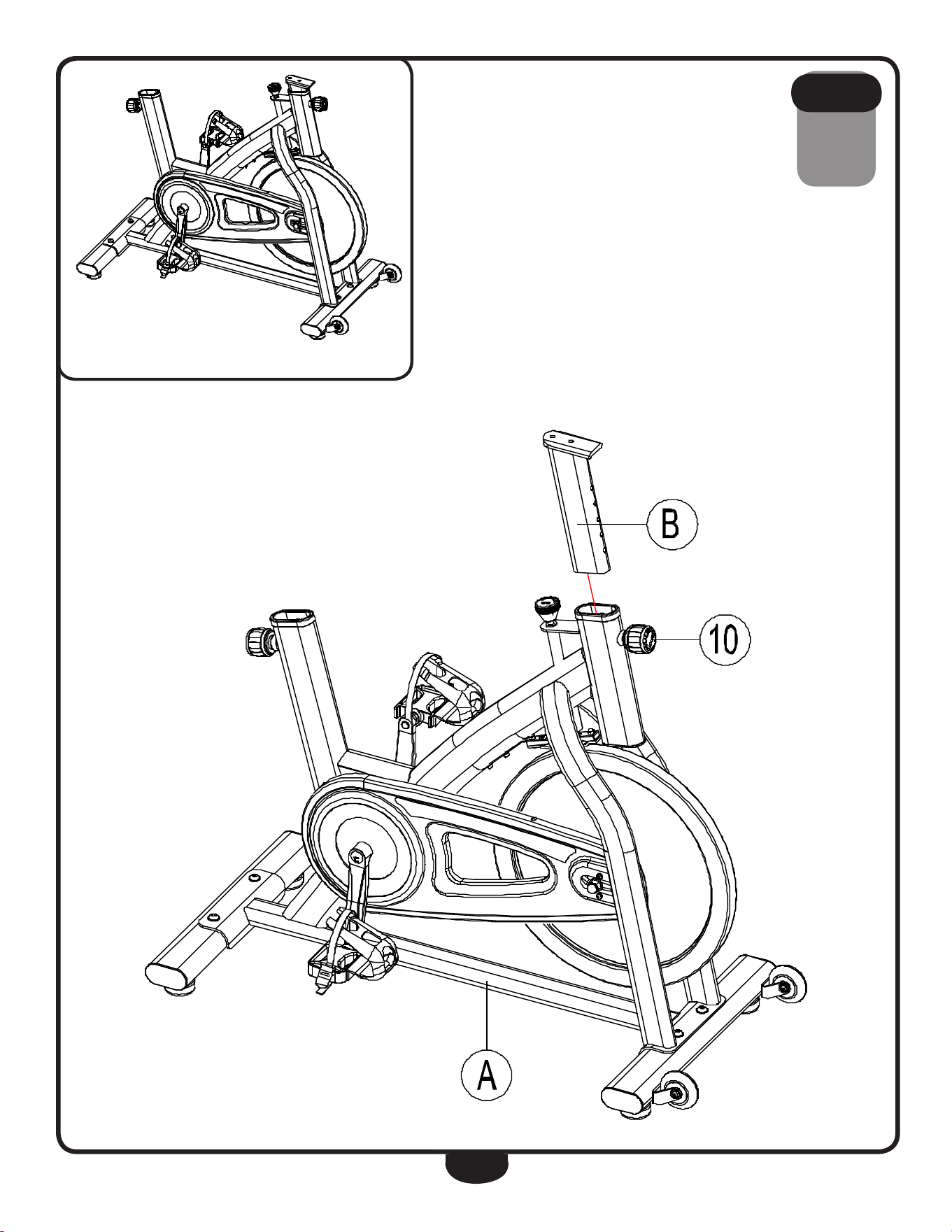
be careful to assemble all components
in the sequence they are presented.
A. loosen Pop Pin (10) and slide handle Bar Post (B) into the handle Bar
Post housing on Main frame (A) as shown.
noTe: Silicone oil may be used to ease gliding on handle Bar Post (B).
B. retighten Pop Pin (10).
s T e p
3
13
s T e p
3
Above shows STeP 3 assembled and completed.
11
Step 3: Assemble the Handlebar Post
Slacken the Pop Pin (10), and slide the Handlebar Post (B) into the Handlebar Post Housing on the Main
Frame (A), and re-tightent the Pop pin (10).
Step 4: Assemble the Handlebar
Fix the Handlebar (D) onto the Handlebar Post (B) and tighten it with Flat Washer20*Φ10*1.5(67) and
Inner Hexagon Flat Round Bolt M10*25L(66).

14
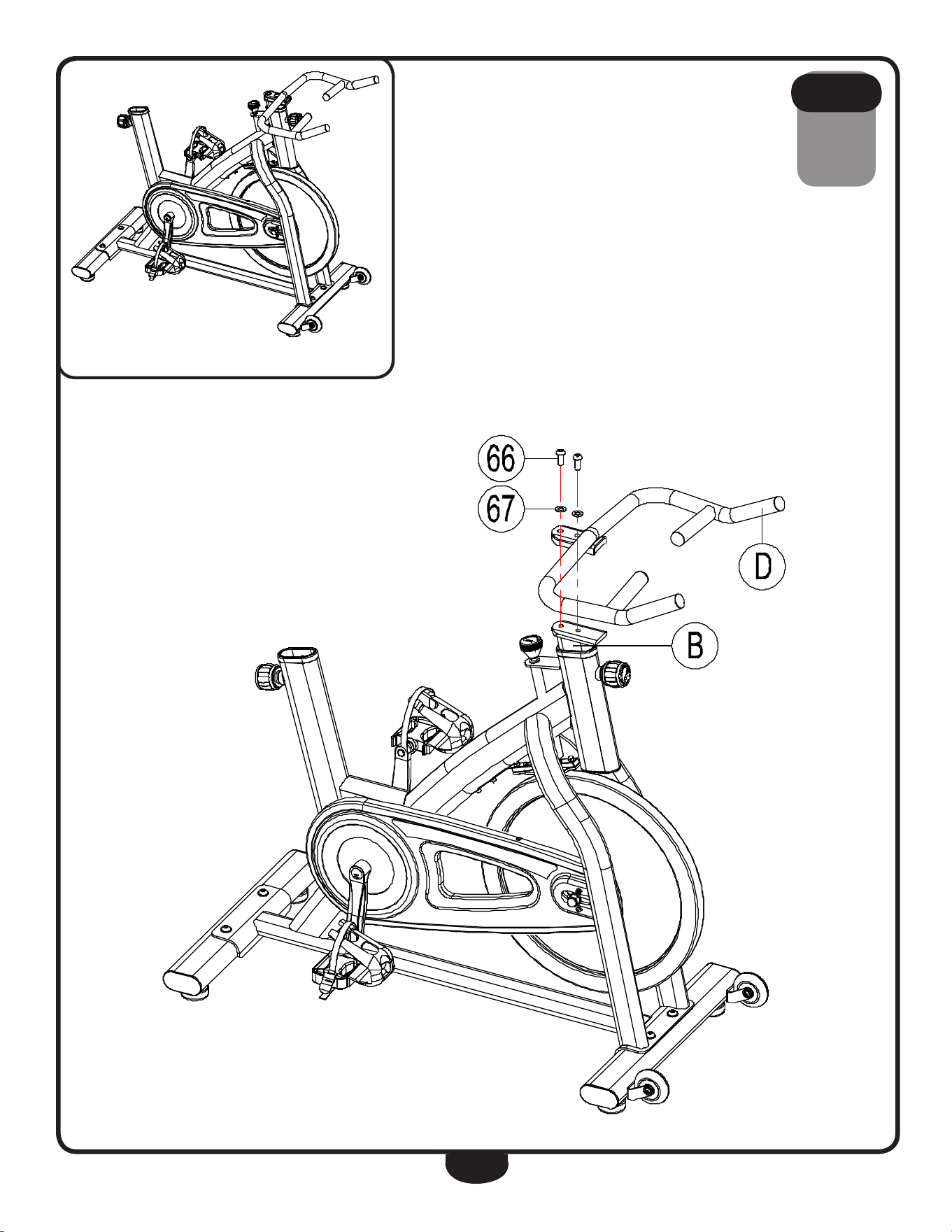
be careful to assemble all components
in the sequence they are presented.
noTe: black hardware is used in this step.
A. Connect handle Bar (d) to handle Bar Post (B) using:
two 66 (m10 round allen head bolt)
two 67 (m10 washer)
s T e p
4
15
s T e p
4
Above shows STeP 4 assembled and completed.
11
Step 3: Assemble the Handlebar Post
Slacken the Pop Pin (10), and slide the Handlebar Post (B) into the Handlebar Post Housing on the Main
Frame (A), and re-tightent the Pop pin (10).
Step 4: Assemble the Handlebar
Fix the Handlebar (D) onto the Handlebar Post (B) and tighten it with Flat Washer20*Φ10*1.5(67) and
Inner Hexagon Flat Round Bolt M10*25L(66).

16
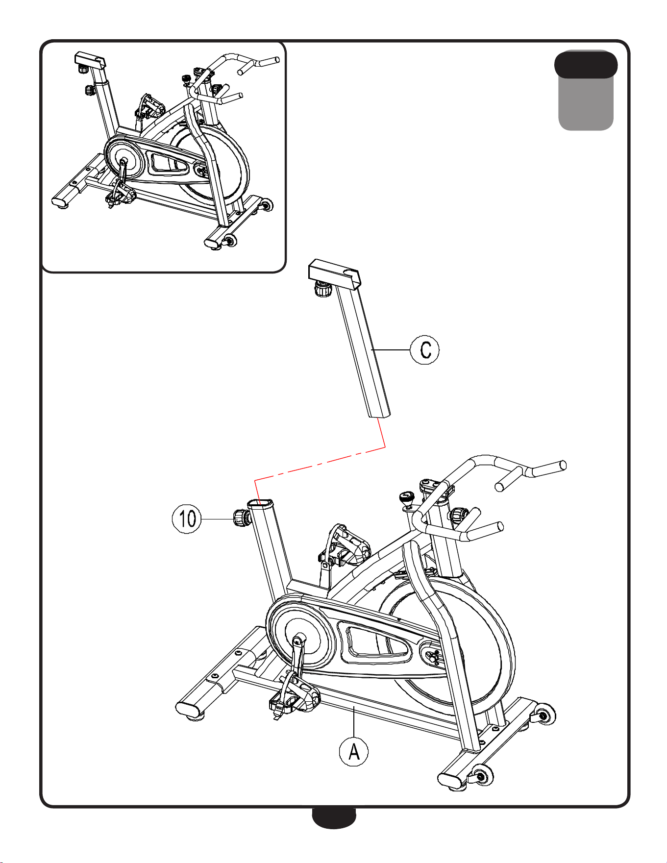
be careful to assemble all components
in the sequence they are presented.
A. loosen Pop Pin (10) and slide Seat Post (C) into the Seat Post housing on
Main frame (A).
noTe: Silicone oil may be used to ease gliding on Seat Post (C).
B. retighten Pop Pin (10).
s T e p
5
17
s T e p
5
Above shows STeP 5 assembled and completed.
12
Step 5: Assemble the Seat Post
Slacken the Pop Pin (10), and slide the Seat Post (C) into the Seat Post Housing on the Main Frame, then
retighten the Pop Pin (10).
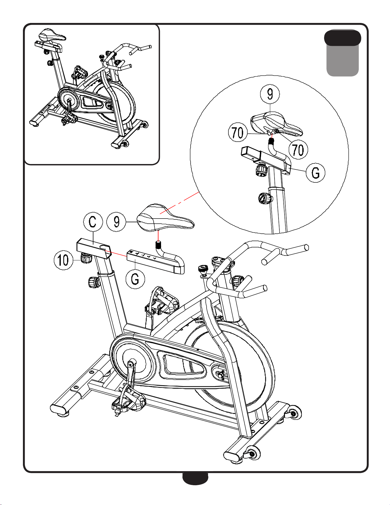
Step 6: Assemble the Seat
Slacken the Pop Pin (10) and slide the Seat Slider (G) into the Seat Post (C), then re-tighten the Pop Pin,
and fix the seat (9) onto the seat slider.
Step 7: Installation completed.
After finishing installation, please inspect all the screws and nuts carefully to make sure all of them
tightened.
12
Step 5: Assemble the Seat Post
Slacken the Pop Pin (10), and slide the Seat Post (C) into the Seat Post Housing on the Main Frame, then
retighten the Pop Pin (10).
Step 6: Assemble the Seat
Slacken the Pop Pin (10) and slide the Seat Slider (G) into the Seat Post (C), then re-tighten the Pop Pin
(10), and fetch out the Seat (9), slacken a little of the Hexagon Nut (70) counter-clockwise by using an
opening wrench, then fix the Seat (9) onto the Seat Slider (G), then use the opening wrench to lock up the
Hexagon Nut (70) clockwise.
Step 7: Installation completed.
After finishing installation, please inspect all the screws and nuts carefully to make sure all of them
tightened.

18
be careful to assemble all components
in the sequence they are presented.
A. loosen Pop Pin (10) and slide Seat glider (g) into Seat Post (C) as shown.
noTe: Silicone oil may be used to ease gliding on Seat glider (g).
B. retighten Pop Pin (10).
C. Insert Seat (9) onto the vertical shaft of Seat glider (g).
d. Secure Seat (9) by tightening both nuts (70).
noTe: Make sure Seat (9) faces forward when aligned with Main frame (A).
e. Congratulations!! You have completed the installation of your new BfSB5.
s T e p
6
19
s T e p
6
Above shows STeP 6 assembled and completed.
12
Step 5: Assemble the Seat Post
Slacken the Pop Pin (10), and slide the Seat Post (C) into the Seat Post Housing on the Main Frame, then
retighten the Pop Pin (10).
Step 6: Assemble the Seat
Slacken the Pop Pin (10) and slide the Seat Slider (G) into the Seat Post (C), then re-tighten the Pop Pin,
and fix the seat (9) onto the seat slider.
Step 7: Installation completed.
After finishing installation, please inspect all the screws and nuts carefully to make sure all of them
tightened.
12
Step 5: Assemble the Seat Post
Slacken the Pop Pin (10), and slide the Seat Post (C) into the Seat Post Housing on the Main Frame, then
retighten the Pop Pin (10).
Step 6: Assemble the Seat
Slacken the Pop Pin (10) and slide the Seat Slider (G) into the Seat Post (C), then re-tighten the Pop Pin
(10), and fetch out the Seat (9), slacken a little of the Hexagon Nut (70) counter-clockwise by using an
opening wrench, then fix the Seat (9) onto the Seat Slider (G), then use the opening wrench to lock up the
Hexagon Nut (70) clockwise.
Step 7: Installation completed.
After finishing installation, please inspect all the screws and nuts carefully to make sure all of them
tightened.
20
seTTing up Your bfsb5
plaCement in your home
To make exercise a desirable daily activity for you, the BfSB5 should be placed in a comfortable
and attractive setting. This Spin Bike is designed to use minimal floor space and to fit nicely in your
home.
do not place or operate the BfSB5 outdoors.
do not place the BfSB5 near water or in a high moisture content environment.
It is highly recommended to place a dedicated equipment mat beneath your BfSB5.
A dedicated mat provides superior stability and firmness for a proper workout.
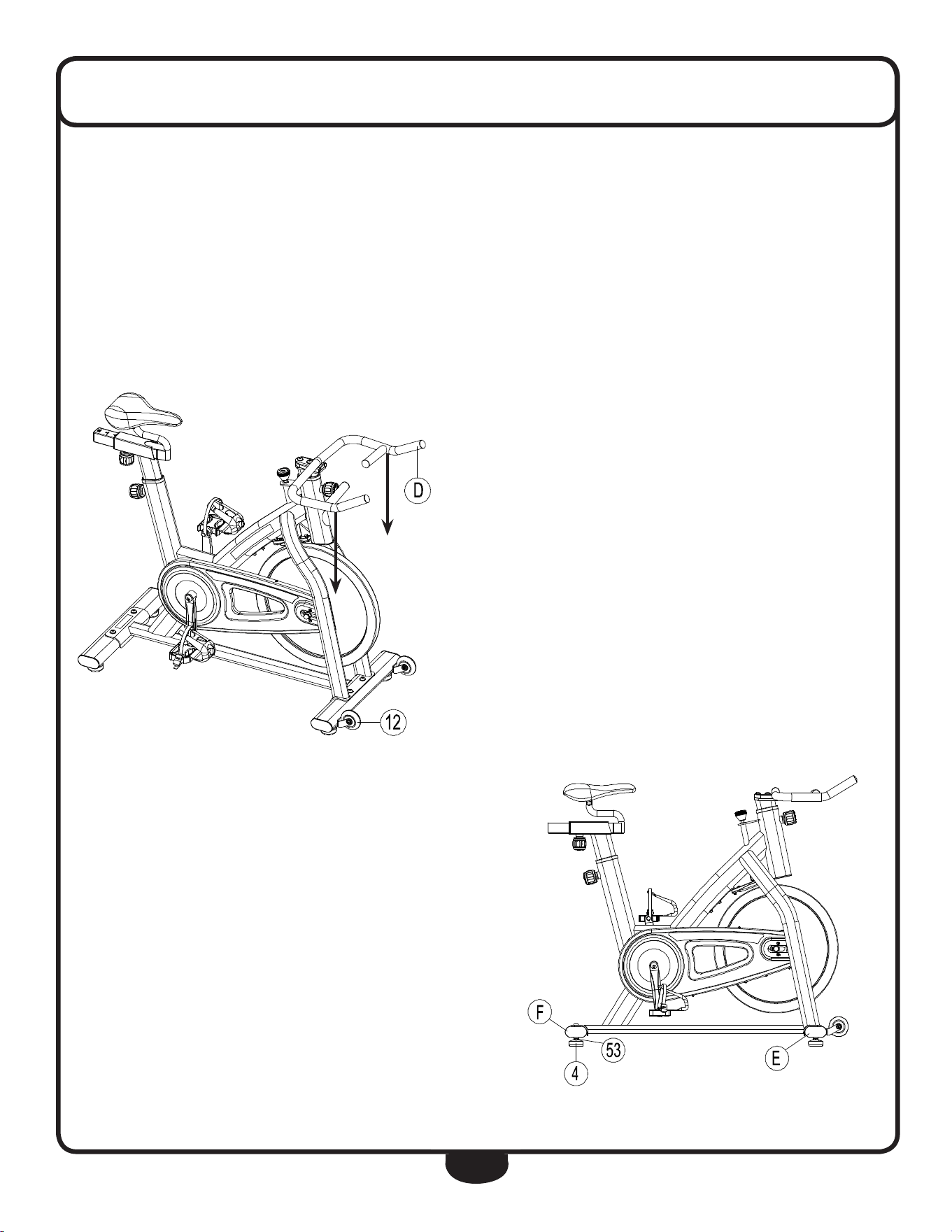
leveling the bfsb5
The front and rear Base levelers (4) can be
adjusted to balance the level the BfSB5.
To adjust the level of the BfSB5,
rotate front or rear Base levelers (4) so
they are at floor level.
once the BfSB5 has been balanced, secure
levelers (4) by locking nut (53) located above
each leveler (4) as shown.
moving the bfsb5
This Spin Bike is easy to move around safely.
To move the BfSB5:
A. grasp handles (d).
B. Carefully pull handles (d) towards you
while pushing the front of the Spin Bike
downward.
C. Simply roll the BfSB5 on Wheels (12)
to the desired location.
d. When the destination has been reached,
gently lower the Spin Bike into position.
13
NOTICE
1. Inspect all the Nuts, Nut Caps and Pedals in safe situation regularly and inspect the Equipment
periodically. While you find any defective parts, replace them immediately. Don’t exercise until they
are repaired well.
2. Pay more attention to easy damage parts. As the following figure, please inspect the Brake pad
cowhide (15) to see if it falls off or is not work before exercise. If it is, please replace it.
3.Before exercise, please inspect the Pedal to see it is loose or not, please repeat installation Step 2 if it is.
4. Please adjust the Hexagon Nut by using the Opening Spanner if the Seat is loose.
6. If you need to move the bike, please grasp the Handlebar (D) at their very ends to make the Pulley (12)
of Front Base stand on floor, then the bike could be moved easily.
20
ADJUSTING THE BASE LEVELER
STEP 1. When you find that the spin bike is not balance on the floor, should adjust one of the Base
Leveler (4), which is higher or lower than the others, to the same level to match the floor and the other
Base Leveler, to reach a balance effect of the spin bike. Then use an opening wrench to lock up the
Hexagon Nut (53) and the Front Base (E) & Rear Base (F).
-END-
21
seTTing up Your bfsb5
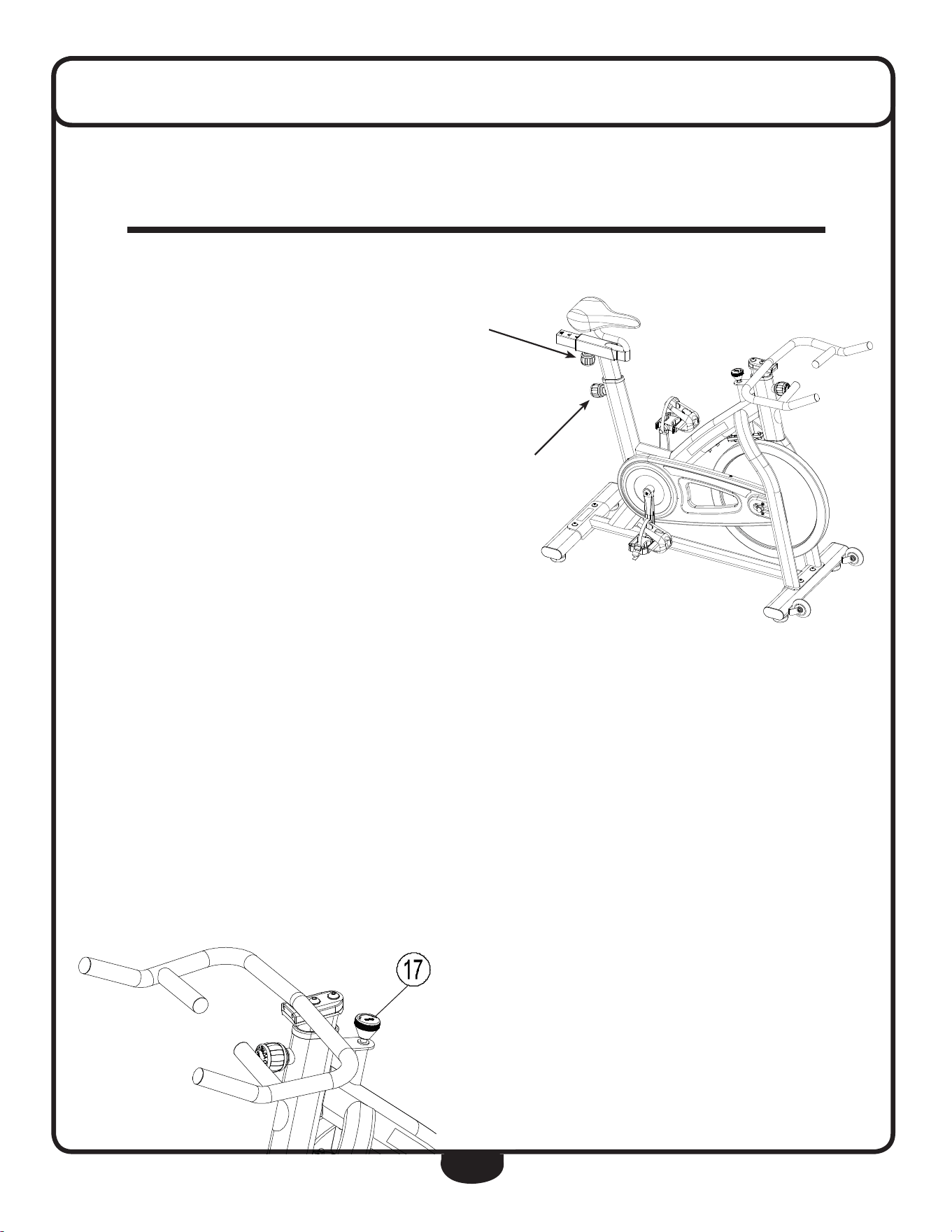
vertiCal seat adJustment
To adjust seat height:
A. Mount onto the BfSB5 spin bike.
B. Step on one pedal after having
brought it to the lowest position.
Make sure your legs are stretched
but do not lock your knees.
Also, seat height should be
level with the user’s hips while
standing adjacent to the seat.
C. If height requires adjustment,
loosen the Pop Pin by turning it
counterclockwise then pull while
adjusting the seat.
d. After adjustment, place the Pop Pin
in the chosen position and lock the Pop Pin by turning it clockwise.
horiZontal seat adJustment
To adjust the seat horizontally:
A. Mount onto the BfSB5 spin bike.
B. Position the pedals so that one pedal is towards the front of the bike and one pedal is towards
the rear of the bike.
C. look down on your forward knee, it should be directly above your front foot for correct posture
otherwise adjustment is required. Also, if the handle Bar is too far to reach, the seat needs to
be adjusted forward.
d. To adjust the seat horizontally, loosen the Pop Pin by turning it counterclockwise then adjust
the seat as needed.
e. After adjustment, place the Pop Pin in the chosen position and lock the Pop Pin by turning the
knob clockwise.
brake adJustment
Varying resistance will increase the
effectiveness of your workout. To increase
brake resistance, rotate Brake Knob (17)
clockwise. rotate Brake Knob (17)
counterclockwise to decrease resistance.
Correct seat posture is important for a beneficial workout. follow the steps below to
optimally custom adjust your BfSB5.
INDOOR EXERCISE BIKE
USER MANUAL
HP-SP0908 (Home Use)
Vertical
Seat Adjustment
Pop Pin
horizontal
Seat Adjustment
Pop Pin
INDOOR EXERCISE BIKE
USER MANUAL
HP-SP0908 (Home Use)
16
STEP 5. Screw on the 2 pcs of Inner hexagon column bolt M5*12L (57) and 2 pcs of Flat washer
5.2*1.0(48), then lock up by using a Inner hexagon wrench.
REPLACING THE BRAKE-KNOB
STEP 1. Slacken the 2 pcs of Inner hexagon column bolt M5*12L (57) by using Inner hexagon wrench.
STEP 2. Take out the 2pcs of Inner hexagon column bolt M5*12L (57) and 2 pcs of Flat washer
5.2*1.0(48) and the brake assembly.
STEP 3. Hold the +H[DJRQQXWE\DRSHQLQJZUHQFKsimultaneously slacken the Brake- Knob (17)
by hand, and take out the Cap nut (55), Hexagon Nut (53), Brake adjusting nut (35), Rubber mat (18),
Brake-Knob (17) and Brake screw (51) one by one.

22
exercise Tips and guidelines
stretCh
Stretching prior to exercising will improve flexibility and reduce chances of exercise related injury.
ease into each of these stretches with a slow gentle motion. hold your stretched position for a count
of ten. do not bounce. repeating the stretching exercises again, after cooling down, will help to
loosen and relax your muscles to prevent soreness after the workout.
warm up
A few minutes of a workout should be devoted to warming up. This warm up time will limber your
muscles and prepare them for a more strenuous exercise. Warm up on the BfSB5 by exercising at
slow or moderate speeds.
Cool down
never stop exercising suddenly. It is a good idea to end a workout slowly since this will allow your
heart to readjust to the decreased demand.
how often?
It is most often recommended that you exercise a few times a week to maintain cardiovascular fit-
ness. If you have other goals such as weight or fat loss, you will achieve your goal faster with more
frequent exercise. remember that your ultimate goal should be to make exercise a lifetime habit.
Many people are successful staying with a fitness program if they set aside a specific time of the day
to exercise. regular exercise is key to a healthy life style
how long?
for a useful workout, always start slowly, especially if you have been sedentary during the past year.
Your body will need time to adjust to the new activity. As your body adjusts, gradually increase your
workout time per session.
Always consult your physician before beginning any exercise program. for your health and
safety, do not over exert yourself. remember to stretch and warm up before each exercise
program.
23
exercise Tips and guidelines
how hard?
how hard you work out is determined by your goal. regardless of your fitness goals, always begin an
exercise program at low intensity. Aerobic exercise does not have to be painful to be beneficial!
There are two ways to measure your exercise intensity. The first is by evaluating your perceived exer-
tion level and the second is by monitoring your heart rate.
during exercise, if you cannot maintain a conversation without gasping, you are working too hard.
A good rule of thumb is to work to the point of exhilaration, not exhaustion. If you cannot catch your
breath, it is time to slow down. Always be aware of other warning signs to overexertion.
To monitor your heart rate you can use a pulse monitor or take your pulse with your fingers. Pulse
monitors are convenient tools for monitoring your heart rate. however, these values are for reference
only. You should always listen to your body first.
You can measure your pulse with your fingers by placing your first two fingers lightly over the blood
vessel (carotid artery) on your neck located next to your Adam’s apple. Count your pulse for ten
seconds and multiply by six. This figure is your heart rate in beats per minute (bpm). Compare this
number to the Target heart rate zone for your age group.
target heart rate
The most common method for calculating your target
heart rate is to find your maximum heart rate.
The standard formula for this is:
220 - your age = maximum heart rate.
You do noT want to workout at your maximum heart rate.
You want to workout in your target heart rate zone.
Your target heart rate zone is a percentage of your
maximum heart rate. The American heart Association
recommends working out at a target heart rate zone
of between 60% - 75% of your maximum heart rate.
If you are just beginning an exercise program,
exercise near or below the lower limit of your target zone.
lower target Zone limit = maximum heart rate x 0.60
uPPer target Zone limit = maximum heart rate x 0.75
If you experience chest pains, nausea, dizziness or shortness of breath, stop exercising im-
mediately and consult your physician before continuing any workouts!
Age Target Zone
20 120 ~ 150
25 117 ~ 146
30 114 ~ 142
35 111 ~ 138
40 108 ~ 135
45 105 ~ 131
50 102 ~ 127
55 99 ~ 123
60 96 ~ 120
65 93 ~ 116
70 90 ~ 113
target heart rate

24
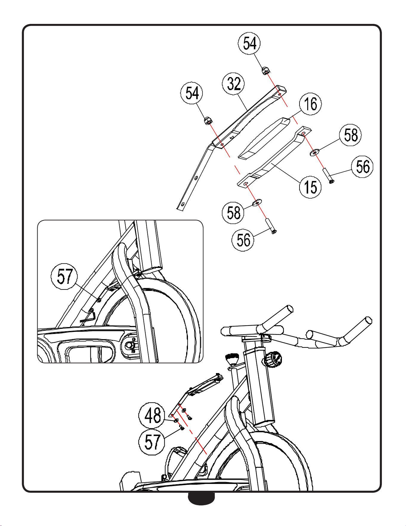
braKe pad replacemenT
replaCing the brake pad
A. remove Allen Bolts (57) and Washers (48) to disassemble the brake
assembly as shown in diagram A.
B. Secure Acorn Cap nut (54) with a wrench then remove Phillips Bolt (56) and
Washer (58).
C. Separate Brake Mat (16) and Brake Pad (15) from Brake holder (32).
d. Clean Brake holder (32).
e. Spread glue on Brake holder (32) then stick the new Brake Mat (16) on
Brake holder (32).
f. Place Brake Pad (15) on top of Brake Mat (16) then secure the assembly
using Allen Bolts (56), washers (48) and Acorn Cap nuts (54).
g. Install the new brake assembly onto the mainframe using Allen Bolts (57) and
Washers (48).
25
15
REPLACING THE BRAKE PAD
STEP 1. Slacken the 2pcs of Inner hexagon column bolt M5*12L (57) by using a Inner hexagon wrench
4#.
STEP 2. Take out the 2pcs of Inner hexagon column bolt M5*12L (57) and 2 pcs of )ODWZDVKHU
DQGWKHEUDNHDVVHPEO\GHWDLOHGLQVWHS
STEP 3. Hold the Cap nut (54) by a wrench, at the same time slacken the 2 pcs of Cross recessed pan
head bolt M5*18L(56) by using a cross screwdriver, then you can take out the 2 pcs of Cross recessed pan
head bolt M5*18L(56), 2 pcs of flat washer8*16*2T (58), cowhide brake pad (15), Brake soft mat
(16), and the Cap nut M5 (54).
STEP 4. Clean the Brake holder (32), then spread the glue on the Brake holder, and follow the figure
below, stick the new Brake soft mat (16) on the brake holder, and then stick the new cowhide brake pad
(15) on the other side of Brake soft mat (16), and lock up the Cross recessed pan head bolt M5*18L(56)
by using a cross screwdriver while holding the Cap nut (54) with the a wrench, and press out the brake
pad (15) to make sure it is completely glued.
diagram A

26
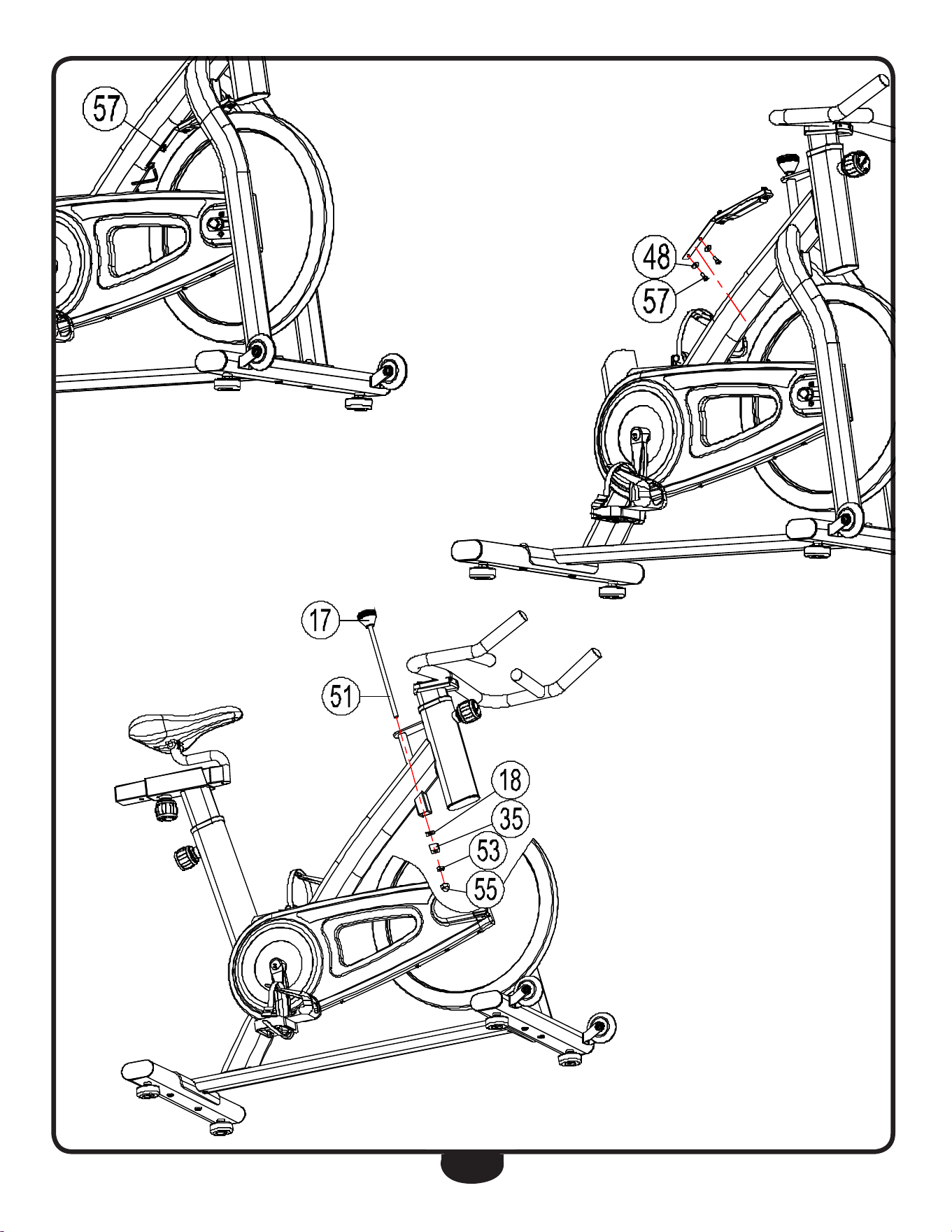
braKe Knob replacemenT
replaCing the brake knob
A. remove Allen Bolts (57) and Washers (48) to disassemble the brake
assembly.
B. While holding nut (53) with a wrench, loosen Brake Knob (17) by hand.
C. remove Acorn Cap nut (55), nut (53), Brake Adjustment nut (35),
rubber Spacer (18), Brake Knob (17) and Brake Screw (51) one at a time.
d. replace Brake Knob (17) then insert Brake Screw (51) into the new
Brake Knob (17) and insert them into the mainframe.
e. replace rubber Spacer (18), Brake Adjustment nut (35), nut (53) and
Acorn Cap nut (55).
f. Tighten nut (53) with a wrench while holding onto Brake Knob (17) by hand.
Make sure Acorn Cap nut (55) is properly secured.
g. Install the brake assembly onto the mainframe using Allen Bolts (57) and
Washers (48).
27
16
STEP 5. Screw on the 2 pcs of Inner hexagon column bolt M5*12L (57) and 2 pcs of Flat washer
5.2*1.0(48), then lock up by using a Inner hexagon wrench.
REPLACING THE BRAKE-KNOB
STEP 1. Slacken the 2 pcs of Inner hexagon column bolt M5*12L (57) by using Inner hexagon wrench.
STEP 2. Take out the 2pcs of Inner hexagon column bolt M5*12L (57) and 2 pcs of Flat washer
5.2*1.0(48) and the brake assembly.
STEP 3. Hold the +H[DJRQQXWE\DRSHQLQJZUHQFKsimultaneously slacken the Brake- Knob (17)
by hand, and take out the Cap nut (55), Hexagon Nut (53), Brake adjusting nut (35), Rubber mat (18),
Brake-Knob (17) and Brake screw (51) one by one.

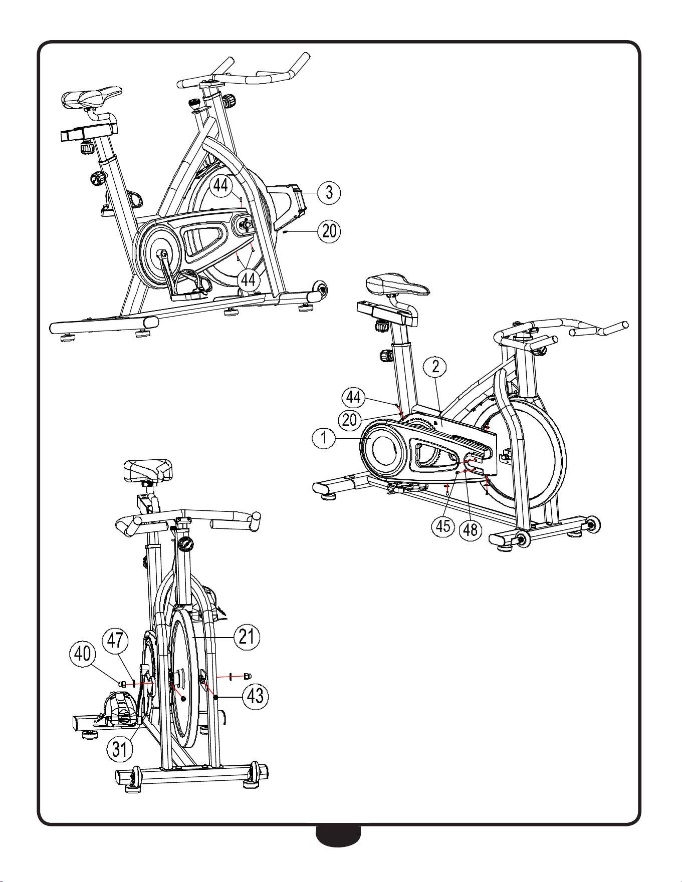
28
cHain replacemenT
replaCing the Chain
A. remove Phillips Pan Screw (44) from front Cover (3) by using a phillips
screwdriver.
B. Take out front Cover (3) and Brake Pad holder nut (20).
C. remove Phillips Pan Screw (44) from Chain Cover A (1).
noTe: Careful not to drop Brake Pad holder nut (20) from Chain Cover B (2).
d. remove Phillips umbrella Screw (45) and Washer (48) then take off Chain
Cover A (1).
e. remove nylon nut (43) from Chain Adjuster (26) then remove Cap nut (40)
and Washer (47).
f. Take off Chain (31) and flywheel (21) one at a time.
g. hang Chain (31) on the flywheel supports then install flywheel (21).
h. replace nylon nut (43), Cap nut (40) and Washer (47). Without tightening
this hardware, adjust Chain (31).
I. Adjust nylon nut (43) on Chain Adjuster (26) as needed making sure they
are reasonably tight and the flywheel is centered on the mainframe.
J. Secure Cap nut (40) and Washer (47) at a strength of 60nM.
K. replace Chain Cover A (1) using Phillips Pan Screw (44), Phillips umbrella
Screw (45) and Washer (48).
l. Set Brake Pad holder nut (20) on front Cover (3) then secure using Phillips Pan
Screw (44).
29
18
REPLACING THE CHAIN
STEP 1. Take out the 3 pcs of Cross Pan Self-tapping Bolt (44) from the front cover (3) by using a cross
screwdriver, then take out the front cover (3) and a Shrapnel nut (20).
STEP 2. Use a cross screwdriver to screw the 4 pcs of Cross Pan Self-tapping Bolt (44) off the Chain
cover A (1), (Note: be careful that do not drop the 4 pcs of Shrapnel nut (20) from the Chain cover B(2)),
screw off the 2 pcs of Cross umbrella screw (45), and 2 pcs of Flat washer5.2*1.0(48), then take off the
Chain cover A(1).
STEP 3. Using a sleeve tool to take off the 2 pcs of Nylon nut M8 (43) from the Chain Adjusting Welding
(26), then use the spanner to take out the 2 pcs of Cap nut M12 (40) and 2 pcs of Flat washer12 (47),
then take off the Chain (31) and the flywheel (21) one by one.
STEP 4. Replacing the new Chain (31), firstly, hang the chain on the flywheel supporting flake, then hang
on the Flywheel (21), screw on the 2 pcs of Nylon nut M8 (43), 2 pcs of Cap nut M12 (40) and 2 pcs of
Flat washer12 (47), no need to lock up, fix the Chain (31).

30
servicing THe bfsb5
Obtaining Service
Please use this Owner’s Manual to make sure all parts have been included in your shipment. When
ordering parts, you must use the part number and description from this Owner’s Manual. Use only
Best Fitness replacement parts when servicing this machine. Failure to do so will void your war-
ranty and could result in personal injury.
For information about product operation or service, go to www.besttness.com or contact an au-
thorized Best Fitness dealer or a Best Fitness factory-authorized service company or contact Best
Fitness customer service at one of the following:
retain this Owner’s Manual for future reference.
Toll free: 1-800-556-3113
phone: 1-708-427-3555
fax: 1-708-427-3556
hours: m-f 8:30-5:00 csT
e-mail: service@bodysolid.com
or write to:
BesT fiTness
service department
1900 s. des plaines Ave.
forest park, iL 60130 usA
www.BestFitness.com
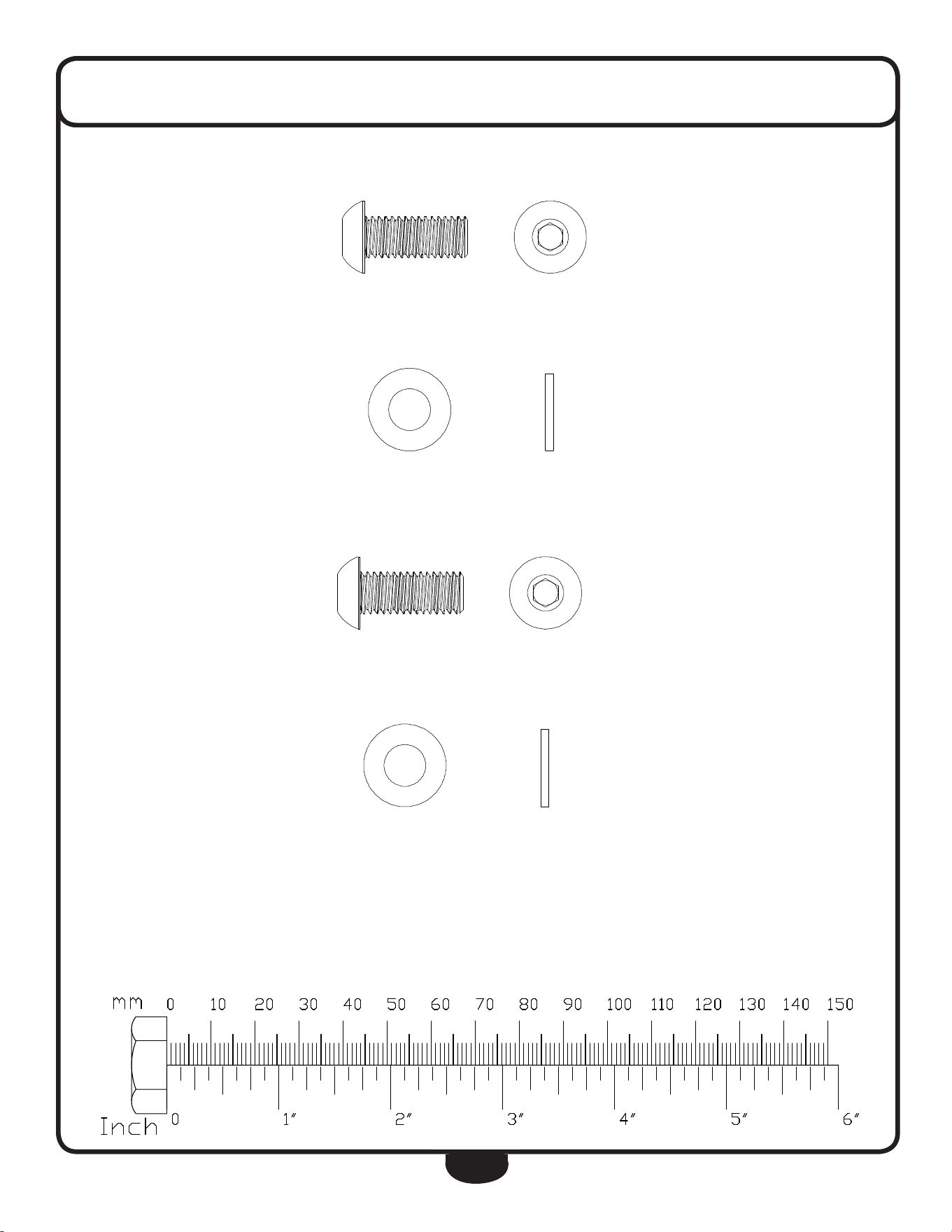
31
HardWare
(actual size shown)
Part# 34 M10x25 Round Allen Head Bolt (CHROME) Qty. 4
Part# 33 M10 Washer (CHROME) Qty. 4
8
8
Part# 66 M10x25 Round Allen Head Bolt (BLACK) Qty. 4
Part# 67 M10 Washer (BLACK) Qty. 4
8
8
8
8

32
HardWare lisT
part# qty description
A 1 Main frame
B 1 handle Bar Post (30 x 70 x 270l x 1.5T) mm
C 1 Seat Post (30 x 70 x 450l x 1.5T) mm
d 1 handle Bar (f28 x 998 x 1.5T) mm
e 1 front Base (40 x 80 x 498l x 1.5T) mm
f 1 rear Base (40 x 80 x 498l x 1.5T) mm
g 1 Seat glider (38 x 38 x 270l x 1.5T) mm
part numbers are required when ordering parts.

33
HardWare lisT
part# qty description
1 1 Chain Cover A
2 1 Chain Cover B
3 1 front Cover (Chain drive)
4 4 Base leveler M10
5 2 Plastic Bushing 40x80x2t (30x70 Id)
6 4 end Cap 40x80x1.5t
7 1 end Cap 40x80x2t
8 1 end Cap 38x38x1.5t
9 1 Seat
10 3 Pop Pin M16xP1.5x35
11 1 Plastic Sheath 45x45x1.5t (38x38 Id)
12 2 Wheel f8xf71.5x223mm
13 2 Spacer f25xf6.5x6
14 1 Plastic Bushing f19xf15.5x40l
15 1 Brake Pad (Cowhide) T4
16 1 Brake Mat 20x11x96mm
17 1 Brake Knob M10
18 1 rubber Spacer f20x2t
19 2 Crank Cover
20 5 Brake Pad holder nut f4.8x0.8t
21 1 flywheel
22 1 Bi-direction Chain Wheel 1 3/8” - 24 unf_rh (T16)
23 2 lock nut 1 3/8” - 24 unf_rh
24 1 flywheel Spindle M12x1.0x154
25 1 Sleeve f18xf12x18t
26 2 Chain Adjuster M8
27 1 Shaft f20x152
28 1 right Crank & Big Chain Wheel 9/16” - 20 unf_rh (52T)
29 1 left Crank (170mm) 9/16” - 20 unf_lh
30 1 right Pedal 9/16” - 20 unf_rh
31 1 Chain 53 section 2~P=12.7
32 1 Brake holder
33 4 Washer f20xf10x1.5 (ChroMe)
34 4 round Allen head Bolt M10x25 (ChroMe)
35 1 Brake Adjustment nut M20x15l
part numbers are required when ordering parts. part numbers are required when ordering parts.

34
HardWare lisT
part# qty description
36 2 Bearing (6001)
37 2 Bearing (6004)
38 4 Bearing (608)
39 2 C-Shaped Buckle f20
40 2 Cap nut M12x1.0
41 2 hex flange nut M10 x P1.25 x 8
42 3 nut M12x1.0
43 2 nylon nut M8
44 7 Phillips Pan Screw ST4.8x15
45 2 Phillips umbrella Screw M5x10
46 2 round Allen head Bolt M6x12
47 2 Washer f12.1xf25x2T
48 6 Washer f5.2x1.0
49 2 Allen Screw f8xM6x30
50 1 Brake Pad holder 1.5T
51 1 Brake Screw f10x245l
52 2 Phillips Bolt M5x25
53 5 nut M10
54 2 nut M5
55 1 Acorn Cap nut M10
56 2 Phillips Bolt M5x18
57 2 Allen Bolt M5x12
58 2 flat Washer f8xf16x2T
59 2 Pedal Sheath
60 2 Pedal Strap
61 1 Phillips umbrella Screw M5x10
62 2 Bf Sticker (Mainframe)
63 1 Bf Sticker (handle Bar)
64 2 Bf Sticker (flywheel)
65 1 Bf Sticker (rear Base)
66 2 round Allen head Bolt M10x25 (BlACK)
67 2 Washer f20xf10x1.5T (BlACK)
68 1 Allen Wrench M6
69 1 Wrench M13, M15
70 2 nut M8
71 1 left Pedal 9/16” - 20 unf_lh
35
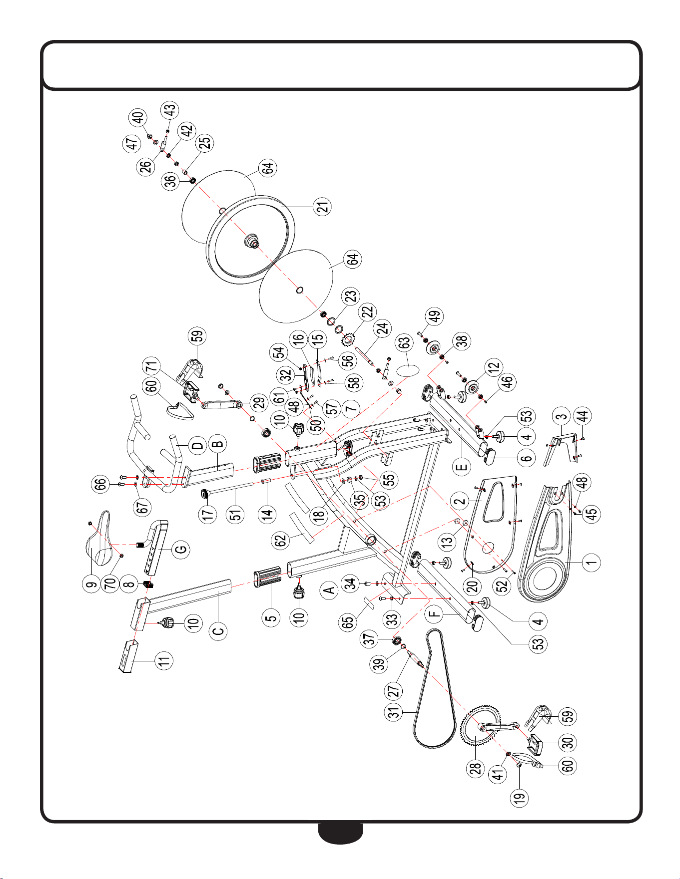
exploded vieW diagram
5
EXPLODED DRAWING
c
Copyright 2010. Body-Solid. All rights reserved. Body-Solid reserves the right to change design and specications when we feel it will improve the product.
Body-Solid machines maintain several patented and patent pending features and designs. All rights reserved on all design patents and utility patents.
www.BestFitness.com
Serial Number is Located on the Frame
model name
:
BFSB5
purchase date
: _______________________________
Serial Number
: _______________________________
INDOOR EXERCISE BIKE
USER MANUAL
HP-SP0908 (Home Use)