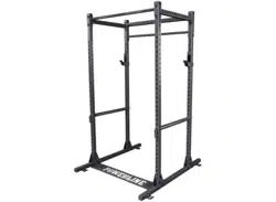
BFPR100B
O W NER’ S MANUA L
V. BFPR100B-20240816
2
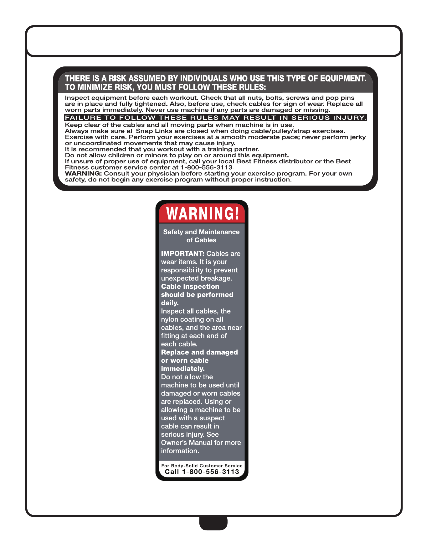
WARNING, SAFETY, & MAINTENANCE
DO NOT REMOVE WARNING LABELS FROM MANUAL OR MACHINE

3
TABLE OF CONTENTS
SAFETY INSTRUCTIONS ............................ PAGE 4
PREPARATION ... ............ ............................ PAGE 5
HARDWARE LIST ...... ...... ............................ PAGE 6
HARDWARE ILLUSTRATION ............................ PAGE 7
PART LIST/ILLUSTRATION ............................ PAGE 8
ASSEMBLY INSTRUCTIONS ............................ PAGE 10
EXPLODED VIEW ...... ...... ............................ PAGE 18
CONTACT PAGE ...... ...... ............................ PAGE 20
4
IMPORTANT SAFETY INSTRUCTIONS
Il est conseille de subir un examen medical complet avant d’entreprendre tout programme d’exercise. Si vous
avez des etourdissements ou des faiblesses, arretez les exercices immediatement.
.
When using exercise equipment, you
should always take basic precautions,
including the following:
• Read all instruction befor using the BFPR100B.
These instructions are writeen to ensure you
safety and to the protect the unit.
• Do not remove any safety labels from the
machine.
• Do not allow children on or near the equipment.
• Ust the equipment only for its intended purpose
as described in this guide. Do not use accessory
attachments that are not recommended by the
manufacturer. Such attachments might cause
injuries.
• Wear proper exercise clothing and shoes for you
workout, no loose clothing.
• Keep hands, limbs, loose clothing, and long hair
well out fo the way of all moving parts.
•
• Do not overexert yourself to work to exhaustion.
• If you feel any pain or abnormal symptoms,
stop your workout immediately and consult your
physician
• Never operate the unit when it has been dropped
or damaged. Return the equipment to a service
center for examination and repair.
• Never drop or insert objects into any opening in
the equipment.
• Always check the unit before each use. Make
sure that all fasteners are secure and in good
working condition.
• Do not use the equipment outdoors or near water.
Personal Safety During Assembly
• Before beginning assembly, please take the time
to read the instructions thoroughly.
• Read each step in the assembly instructions and
follow the steps in sequence. Do no skip ahead.
If you skip ahead, you may learn later that you
have to disassemble components and that you
may have damaged the equipment.
• Assemble and operate the BFPR100B on a solid,
level surface. Locate the unit a few feet from the
walls or furniture to provide easy access.
The BFPR100B is designed for your enjoyment. By
following these precautions and using common
sense, you will have many safe and pleasurable hours
of healthful exercise with your Best Fitness
BF-
PR100B Power Rack.
After assembly, you should check all functions to
ensure correct operation. If you experience problems,
possible errors made during assembly. If you are
unable to correct the problem, call the dealer from
whom you purchased the machine or call
1-800-556-3113 for the dealer nearest you.
Obtaining Service
Please use this Owner’s Manual to make sure that all
parts have been included in your shipment. When
ordering parts, you must use the part number and
description from this Owner’s Manual. Use only
Best Fitness replacement parts when servicing this
machine. Failure to do so will void your warranty and
could result in personal injury.
For information about product operation or service,
Best Fitness dealer or a Best Fitness factory-au-
thorized service company or contact Best Fitness
customer service at one of the following:
Toll Free: 1-800-556-3113
Phone: 1-708-427-3555
Fax: 1-708-427-3556
Hours: M-F 8:30-5:00 CST
E-Mail: [email protected]
Or write to: Best Fitness
Service Department
1900 S. Des Plaines Ave.
Forest Park, IL 60130 USA
Retain this Owner’s Manual for future
reference. If you need to order replacement
parts please be prepared to provide the
following information when contacting us so
that we can assist you better.
1. Model Number
2. Place of Purchase
3. Serial Number (S/N)
4. Part # and Description
5
PREPARATION
ensure that only superior products are released from our factories. Please take the time to carefully read through this
manual thoroughly. Instructions contained in this document are not intended to cover all details or variations possible
with Best Fitness equipment, or to cover every contingency that may be met in conjunction with installation, operation,
maintenance or troubleshooting of the equipment. Even though we have prepared this manual with extreme care,
neither the publisher nor the author can accept responsibility for any errors in, or omission from, the information
given. Should additional information be required, or should situations arise that are not covered by this manual, the
matter should be directed to your local Best Fitness representative, or the Service Department at
Body-Solid Inc. in Forest Park, Illinois.
Any Questions?
Call (800) 556-3113
Thank you for purchasing the BFPR100B. This machine is part of the Best Fitness line of quality strength training
conditioning. To maximize your use of the equipment please study this Owner’s Manual thoroughly.
Required Tools
The basic tools that you must obtain before assembling
the BFPR100B include but are not limited to:
• Metric Allen Key Set
• Standard Allen Key Set
• Standard Wrench Set
• Metric Wrench Set
• Adjustable Wrench
• Screwdriver (standard and/or phillips)
Installation Requirements
Follow these installation requirements when assembling
the BFPR100B:
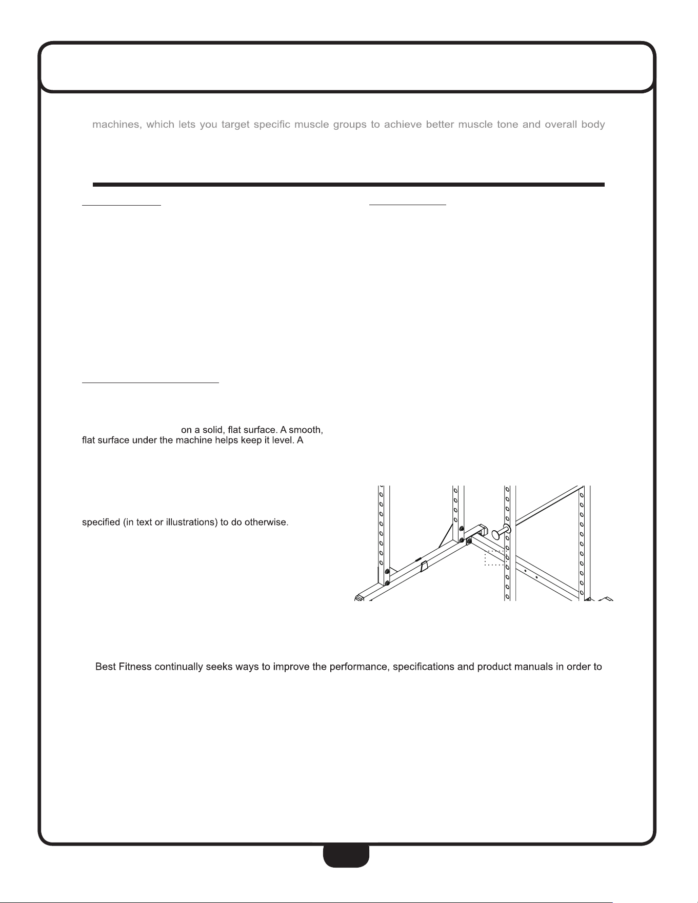
Set up the BFPR100B
level machine has fewer malfunctions.
Provide ample space around the machine. Open
space around the machine allows for easier access.
Insert all bolts in the same direction. For aesthetic
purposes, insert all bolts in the same direction unless
Leave room for adjustments. Tighten fasteners such as
bolts, nuts, and screws so the unit is stable, but leave
room for adjustments. Do not fully tighten fasteners
until instructed in the assembly steps to do so.
Fill out and mail the warranty card.
Assembly Tips
Read all “Notes” on each page before beginning each
step.
While you may be able to assemble the BFPR100B us-
ing the illustrations only, important safety notes and other
tips are included in the text.
Some pieces may have extra holes that you will not use.
Use only those holes indicated in the instructions and
illustrations.
NOTE: With so many assembled parts, proper
alignment and adjustment is critical. While
tightening the nuts and bolts, be sure to leave
room for adjustments.
NOTE: The bottles that are marked “Poison” is your
touch up paint. Keep away from children.
CAUTION: Obtain assistance! If you feel like you can’t
assemble the BFPR100B by yourself then do
not attempt to do so as this could result in
injury. Review the installation requirements
before proceeding with the following steps.
Your S/N# can
be found here
↑

6
PFPR100B - HARDWARE LIST
PART#
1
2
3
4
Part numbers are required when ordering parts.
SIZE
M10X70mm
M10X75mm
ø11Xø30X2.5mm
M10
DESCRIPTION
HEX HEAD BOLT
HEX HEAD BOLT
FLAT WASHER
NYLON LOCK NUT
QUANTITY
12 PCS.
8 PCS.
40 PCS.
20 PCS.
7
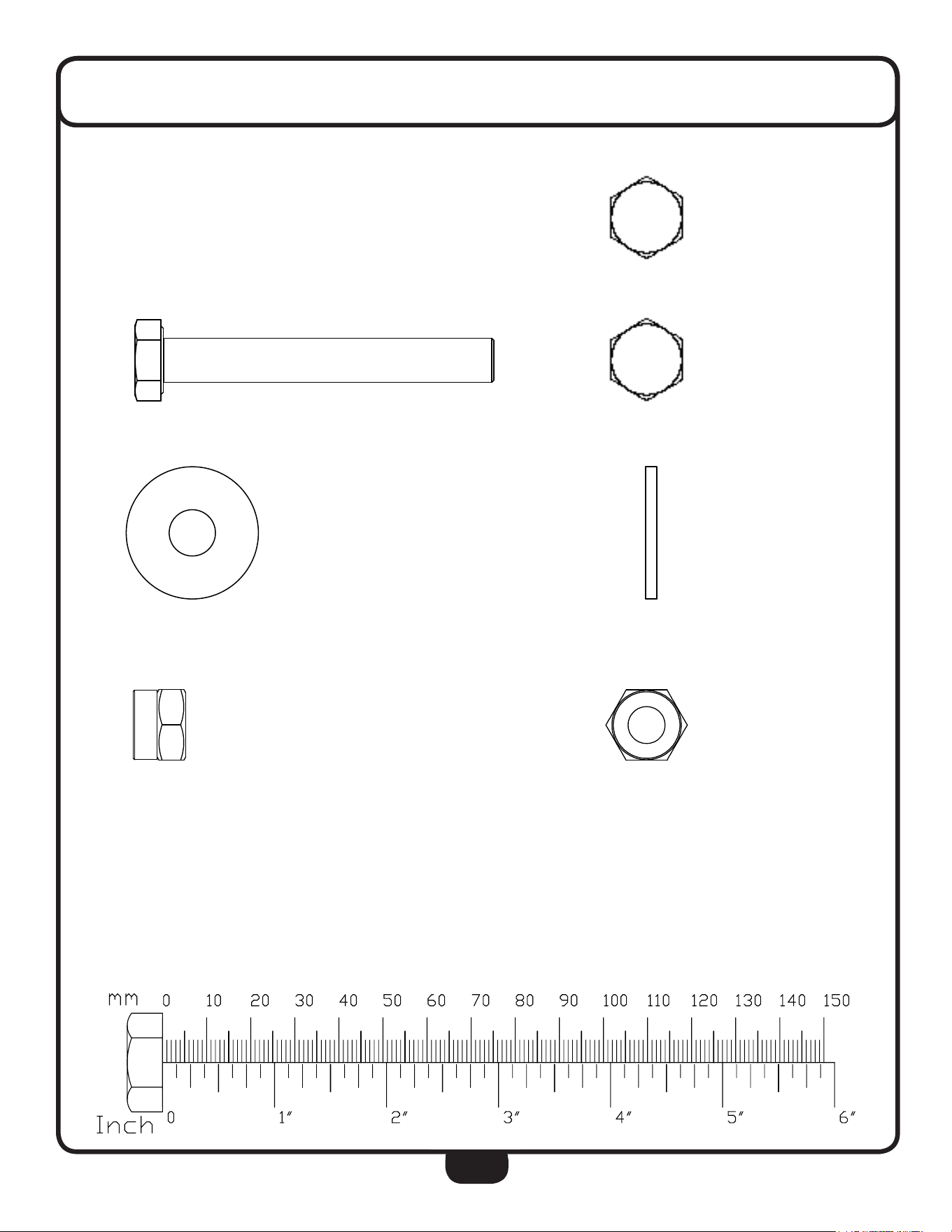
HARDWARE ILLUSTRATION
Part #1 HEX HEAD BOLT M10X70mm QTY. 12
Part #2 HEX HEAD BOLT M10X75mm QTY. 8
Part #3 FLAT WASHER ø11Xø30X2.5mm QTY. 40
Part #4 NYLON LOCK NUT M10 QTY. 20
'21276&$/('5$:,1*
KH[DJRQKHDGEROWVSURGXFWJUDGHFJE*%B)$67(
6+((72)
81/(6627+(5:,6(63(&,),('
6&$/(
:(,*+7
5(9
':*12
$
6,=(
7,7/(
1$0(
'$7(
&200(176
4$
0)*$335
(1*$335
&+(&.('
'5$:1
),1,6+
0$7(5,$/
72/(5$1&,1*3(5
,17(535(7*(20(75,&
7:23/$&('(&,0$/
352+,%,7('
7+5((3/$&('(&,0$/
%(1'
35235,(7$5<$1'&21),'(17,$/
$33/,&$7,21
86('21
1(;7$66<
',0(16,216$5(,1,1&+(6
72/(5$1&(6
)5$&7,21$/
$1*8/$50$&+
7+(,1)250$7,21&217$,1(',17+,6
'5$:,1*,67+(62/(3523(57<2)
,16(57&203$1<1$0(+(5(!$1<
5(352'8&7,21,13$5725$6$:+2/(
:,7+2877+(:5,77(13(50,66,212)
,16(57&203$1<1$0(+(5(!,6
'21276&$/('5$:,1*
SODLQZDVKHUVOVHULHVJUDGHVD
6+((72)
81/(6627+(5:,6(63(&,),('
6&$/(
:(,*+7
5(9
':*12
$
6,=(
7,7/(
1$0(
'$7(
&200(176
4$
0)*$335
(1*$335
&+(&.('
'5$:1
),1,6+
0$7(5,$/
72/(5$1&,1*3(5
,17(535(7*(20(75,&
7:23/$&('(&,0$/
352+,%,7('
7+5((3/$&('(&,0$/
%(1'
35235,(7$5<$1'&21),'(17,$/
$33/,&$7,21
86('21
1(;7$66<
',0(16,216$5(,1,1&+(6
72/(5$1&(6
)5$&7,21$/
$1*8/$50$&+
7+(,1)250$7,21&217$,1(',17+,6
'5$:,1*,67+(62/(3523(57<2)
,16(57&203$1<1$0(+(5(!$1<
5(352'8&7,21,13$5725$6$:+2/(
:,7+2877+(:5,77(13(50,66,212)
,16(57&203$1<1$0(+(5(!,6
'21276&$/('5$:,1*
SUHYDLOLQJWRUTXHW\SHVW\OHJE*%B+(;$*
6+((72)
81/(6627+(5:,6(63(&,),('
6&$/(
:(,*+7
5(9
':*12
$
6,=(
7,7/(
1$0(
'$7(
&200(176
4$
0)*$335
(1*$335
&+(&.('
'5$:1
),1,6+
0$7(5,$/
72/(5$1&,1*3(5
,17(535(7*(20(75,&
7:23/$&('(&,0$/
352+,%,7('
7+5((3/$&('(&,0$/
%(1'
35235,(7$5<$1'&21),'(17,$/
$33/,&$7,21
86('211(;7$66<
',0(16,216$5(,1,1&+(6
72/(5$1&(6
)5$&7,21$/
$1*8/$50$&+
7+(,1)250$7,21&217$,1(',17+,6
'5$:,1*,67+(62/(3523(57<2)
,16(57&203$1<1$0(+(5(!$1<
5(352'8&7,21,13$5725$6$:+2/(
:,7+2877+(:5,77(13(50,66,212)
,16(57&203$1<1$0(+(5(!,6
8
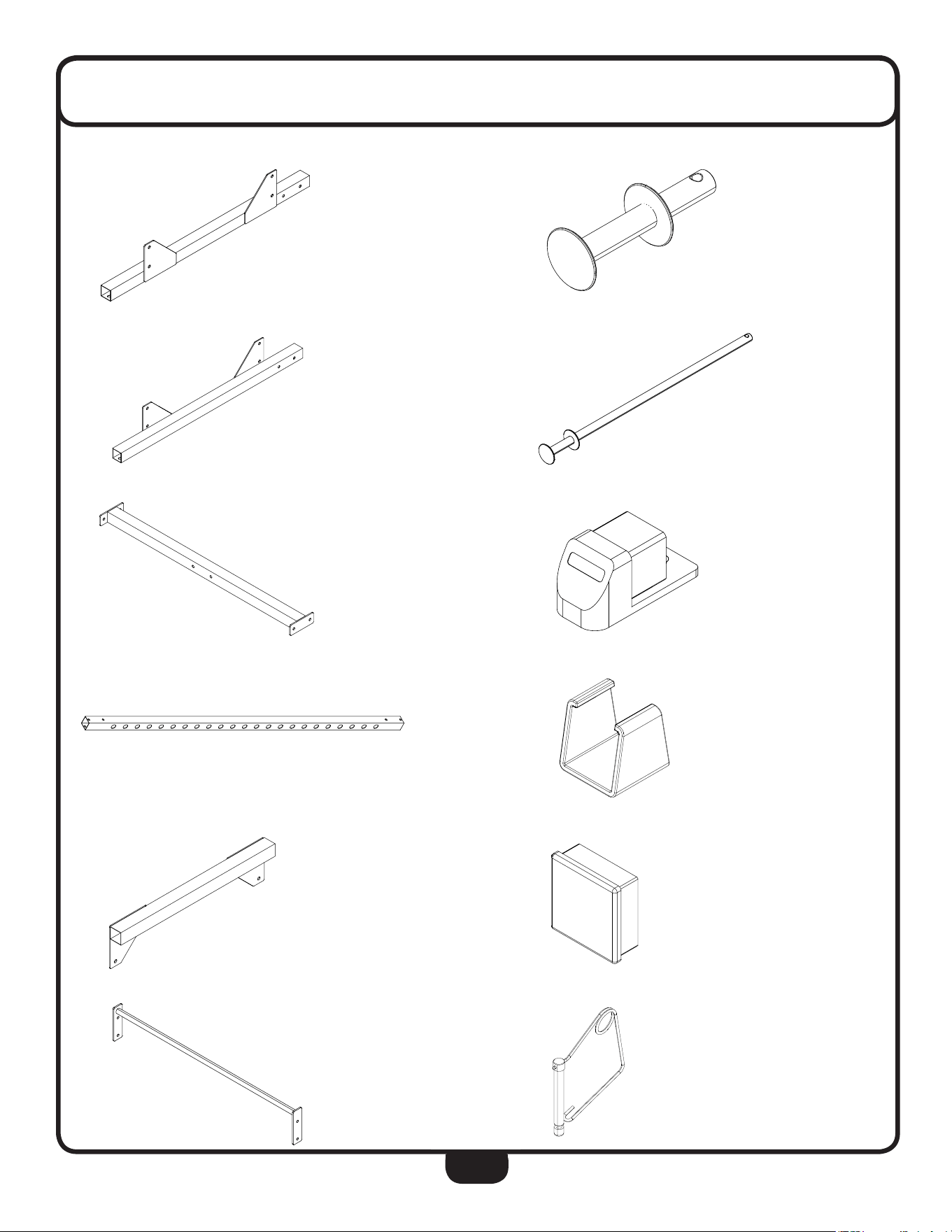
PART LIST/ILLUSTRATION
PART A -- FRAME A, 1 PCS
PART B -- FRAME B, 1 PCS
PART C -- FRAME C, 2 PCS
PART D -- FRAME D, 4 PCS
PART E -- FRAME E, 2 PCS
PART F -- CHIN UP BAR, 1 PCS
PART G -- LIFT OFF, 2 PCS
PART H -- SAFETY CATCH, 2 PCS
PART #5 -- FOOT CAP, 4 PCS
PART #6 -- CLIP-ON SPACER, 2 PCS
PART #7 -- END CAP, 4 PCS
PART #8 -- SAFETY PIN, 4 PCS

9
NOTE

10
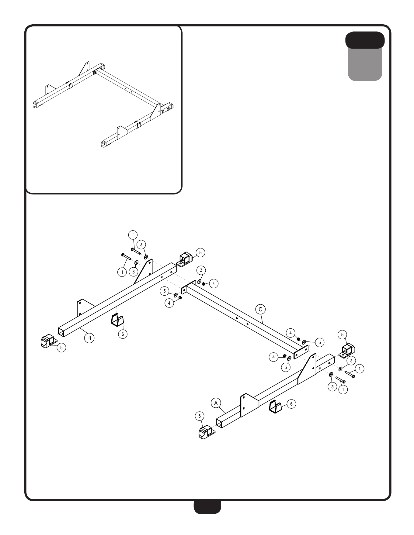
STEP
1
Be careful to assemble all components
in the sequence they are presented.
NOTE:
Finger tighten all hardware in this step. DO NOT wrench tighten until the last step.
Some components may be pre-assembled. Nylon lock nuts will not fully screw onto
bolts, they must be wrench tighten to fully go on.
1A. Install four Foot Caps (#5) in Frame A (A) and Frame B (B).
1B. Install two Clip-On Spacers (#6) on Frame A (A) and Frame B (B).
1C. Attach Frame A (A) and Frame B (B) to Frame C (C) using:
4 - (#1) M10X70mm Hex Head Bolt
8 - (#3) ø11Xø30X2.5mm Flat Washer
4 - (#4) M10 Nylon Lock Nut
11
STEP
1
Above shows STEP 1 assembled and completed.

12
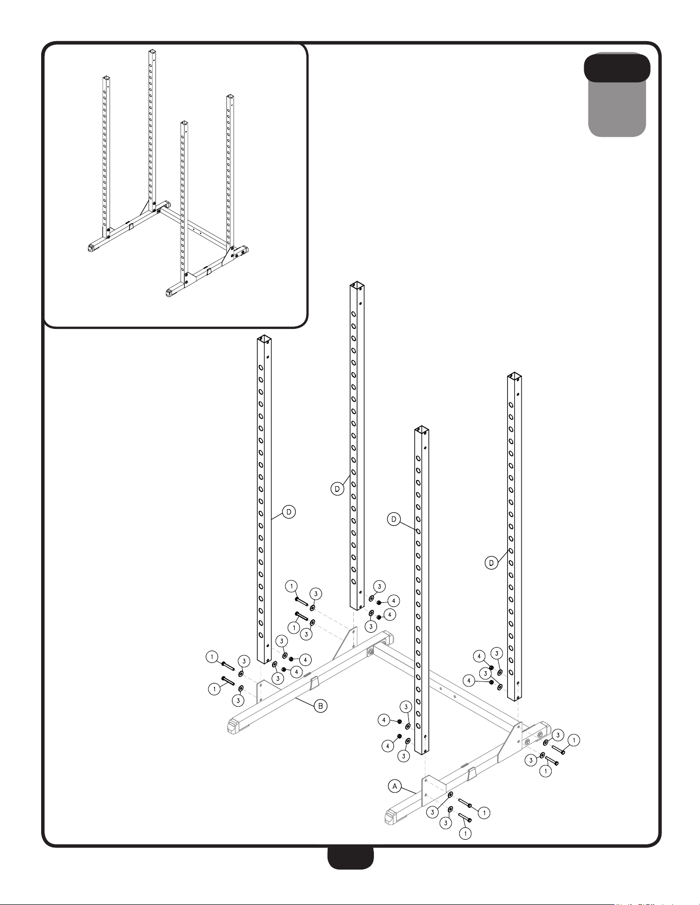
STEP
2
Be careful to assemble all components
in the sequence they are presented.
NOTE:
Finger tighten all hardware in this step. DO NOT wrench tighten until the last step.
Some components may be pre-assembled. Nylon lock nuts will not fully screw onto
bolts, they must be wrench tighten to fully go on.
2A. Attach two Frame D (D) to Frame A (A) using:
4 - (#1) M10X70mm Hex Head Bolt
8 - (#3) ø11Xø30X2.5mm Flat Washer
4 - (#4) M10 Nylon Lock Nut
2B. Attach two Frame D (D) to Frame B (B) using:
4 - (#1) M10X70mm Hex Head Bolt
8 - (#3) ø11Xø30X2.5mm Flat Washer
4 - (#4) M10 Nylon Lock Nut
13
STEP
2
Above shows STEP 2 assembled and completed.

14
STEP
3
3A. Install four End Caps (#7) in two Frame E (E).
3B. Attach one ends of two Frame E (E) and Frame C (C) to Frame D (D) using:
4 - (#2) M10X75mm Hex Head Bolt
8 - (#3) ø11Xø30X2.5mm Flat Washer
4 - (#4) M10 Nylon Lock Nut
3C. Attach another ends of Frame E (E) and Chin Up Bar (F) to Frame D (D)
using:
4 - (#2) M10X75mm Hex Head Bolt
8 - (#3) ø11Xø30X2.5mm Flat Washer
4 - (#4) M10 Nylon Lock Nut
Be careful to assemble all components
in the sequence they are presented.
NOTE:
Finger tighten all hardware first in this step. Wrench tighten ALL hardware at the
end of STEP 3C. Some components may be pre-assembled. Nylon lock nuts will not
fully screw onto bolts, they must be wrench tighten to fully go on.
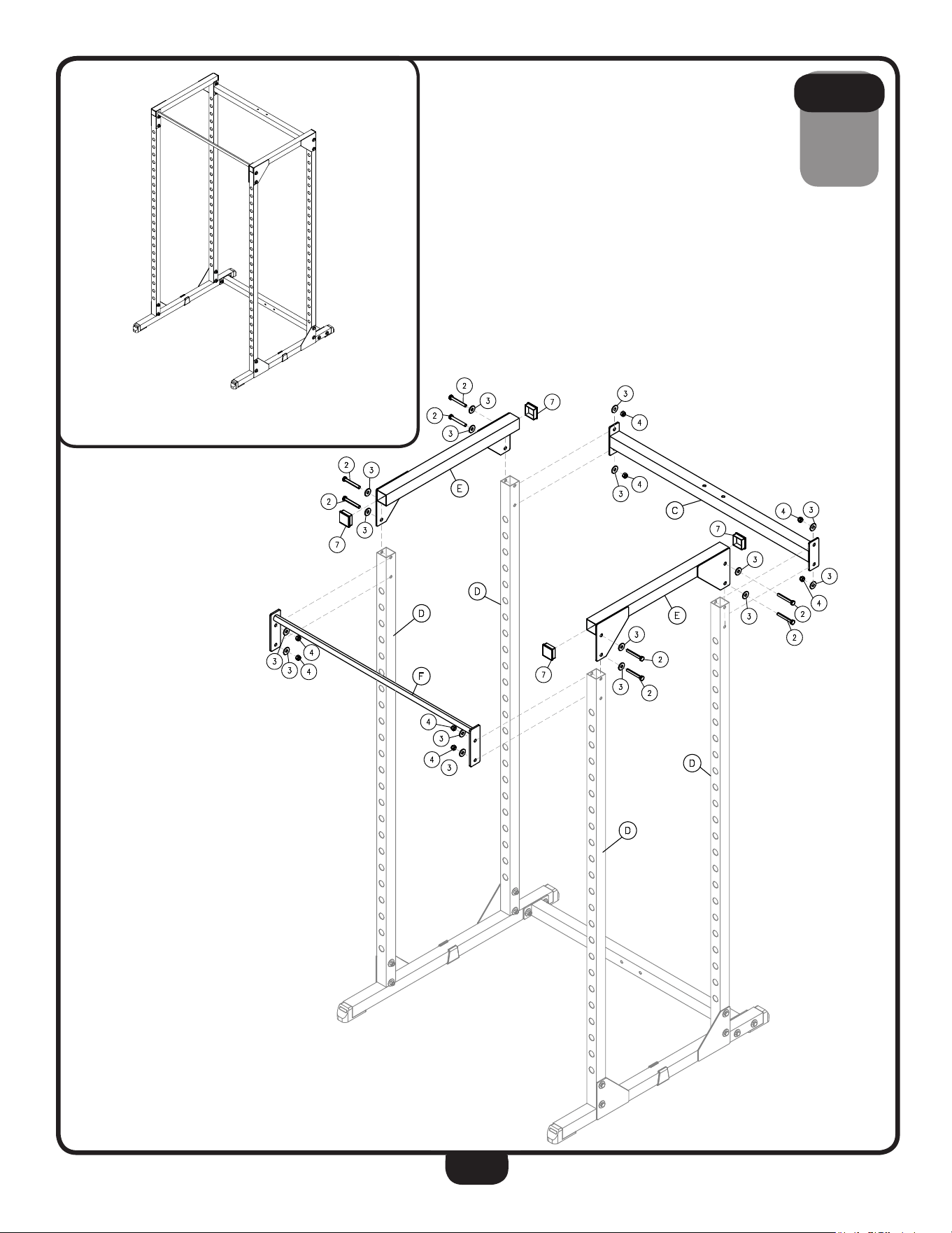
15
STEP
3
Above shows STEP 3 assembled and completed.

16
STEP
4
4A. Insert Safety Catches (H) and Lift Offs (G) into desired positions.
4B. Insert the Safety Pins (#8) at the ends of the Safety Catches (H) and Lift
Offs (G).
NOTE:
Please make sure the Safety Pins (#8) are fully engaged after Safety
Catches (H) and Lift Offs (G) are inserted into the Frames.
Be careful to assemble all components
in the sequence they are presented.
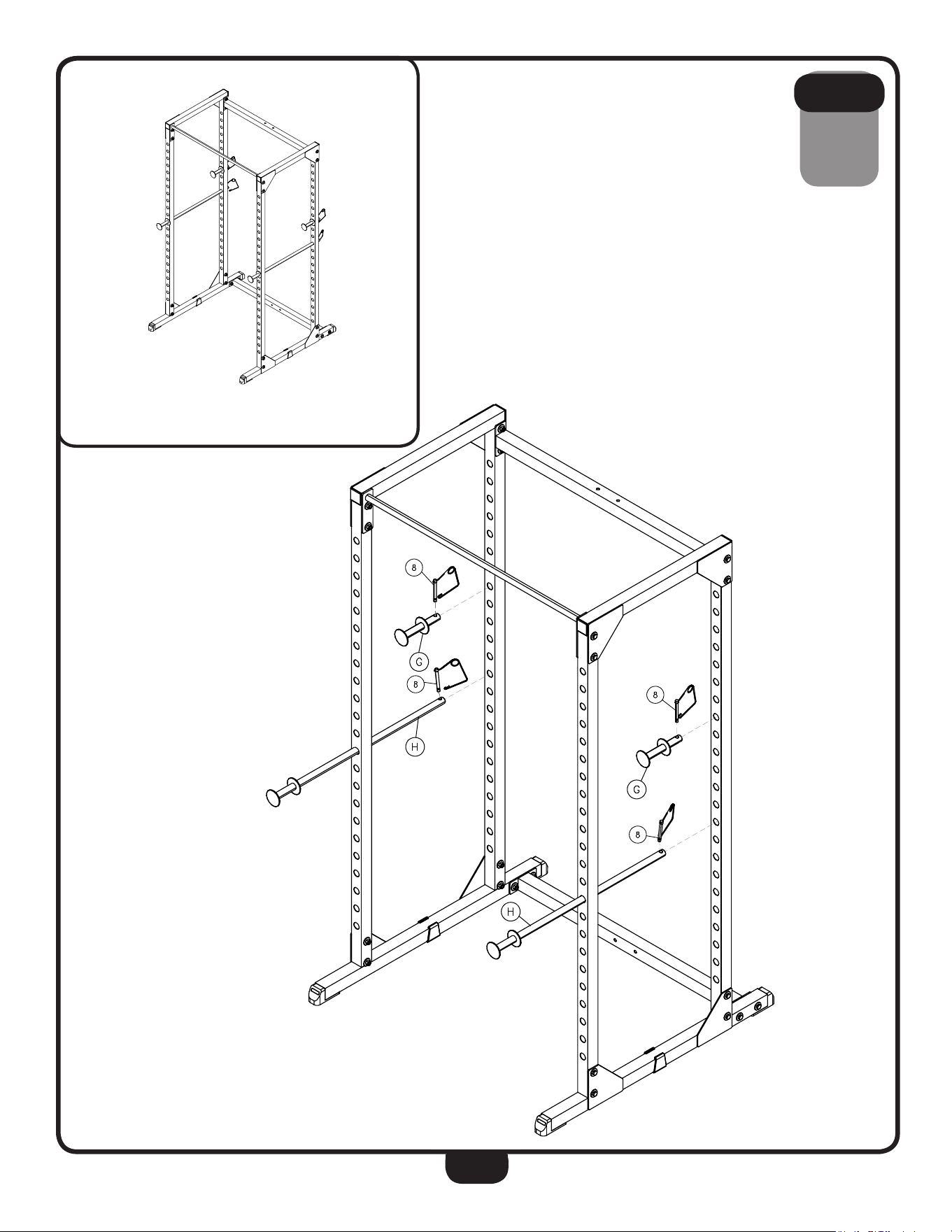
17
STEP
4
Above shows STEP 4 assembled and completed.
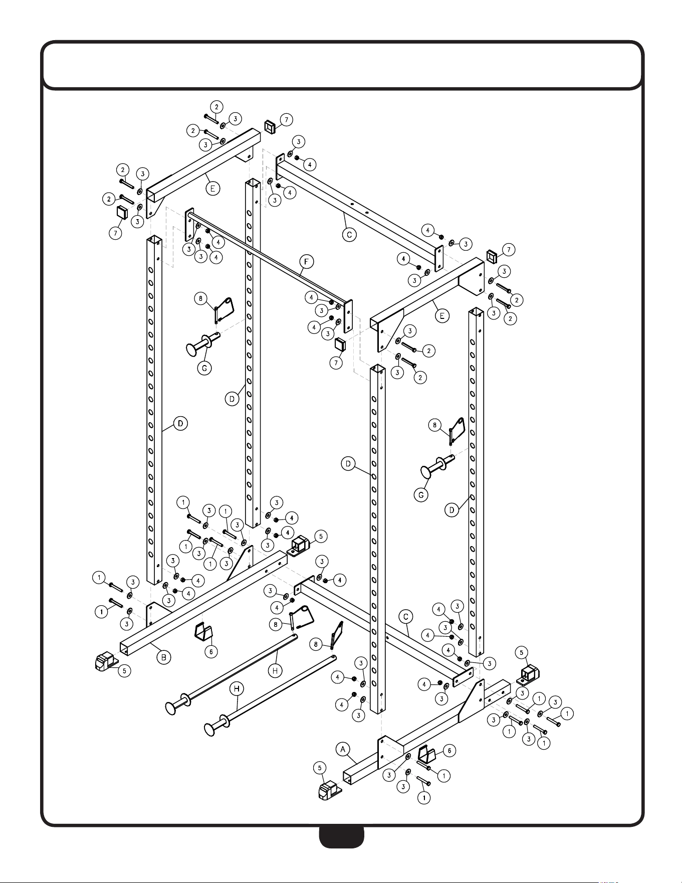
18
EXPLODED VIEW DIAGRAM

BFPR100B
S/N # 008274