V PPR1000-092018
Owner’s Manual
WWW.BODYSOLID.COM
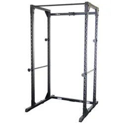
PPR1000
POWER RACK
2
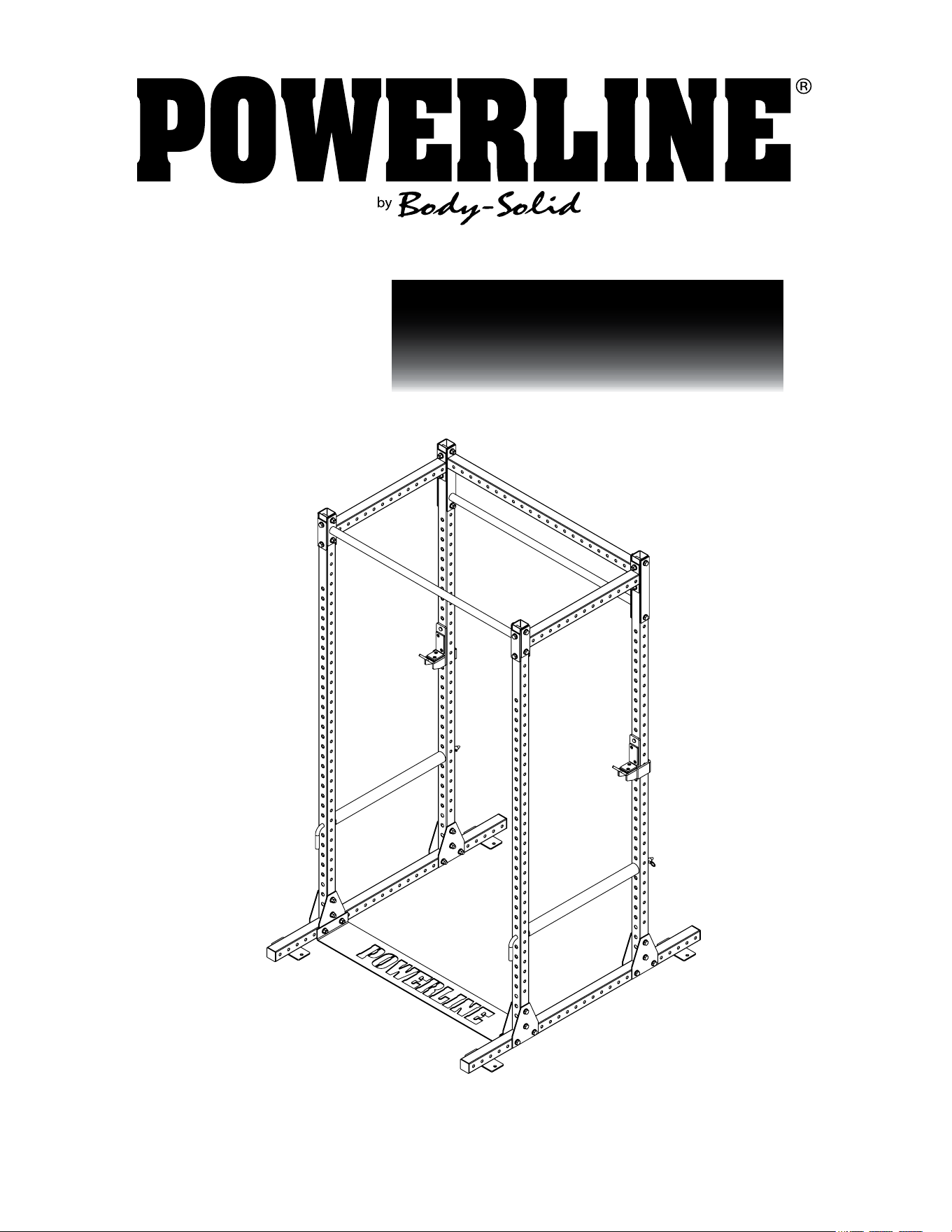
WARNING
Safety and Maintenance
of Cables
IMPORTANT: Cables are
wear items. It is your
responsibility to prevent
unexpected breakage.
Cable inspection should
be performed daily.
Inspect all cables, the
nylon coating on all
cables, and the area
near the fitting at each
end of each cable.
Replace any damaged or
worn cable immediately.
Do not allow the machine
to be used until damaged
or worn cables are
replaced. Using or allowing
a machine to be used
with a suspect cable can
result in serious injury. See
Owner’s Manual for more
information.
For Body-Solid Customer Service
Call 1-800-556-3113

3
PPR1000
TABLE OF CONTENTS
•SAFETY INSTRUCTIONS.......................
•PREPARATION.......................................
•PART/HARDWARE LIST..........................
•HARDWARE ILLUSTRATION.................
•ASSEMBLY INSTRUCTIONS.................
•EXPLODED VIEW...................................
•CONTACT PAGE.....................................
PAGE 4
PAGE 5
PAGE 6
PAGE 7
PAGE 8
PAGE 17
PAGE 18

4
PPR1000
SAFETY INSTRUCTIONS
When using exercise equipment,
you should always take basic
precautions including the
following:
• ReadallinstructionsbeforeusingthePPR1000.
Theseinstructionsarewrittentoensureyoursafety
andtoprotecttheunit.
• Donotremoveanysafetylabelsfromthe
machine.
• Donotallowchildrenonorneartheequipment.
• Usetheequipmentonlyforitsintendedpurpose
asdescribedinthisguide.Donotuseaccessory
attachmentsthatarenotrecommendedbythe
manufacturer.Suchattachmentsmightcauseserious
injuries.
• Wearproperexcerciseclothingandshoesforyour
workout,nolooseclothing.
• Keephands,limbs,looseclothing,andlonghairwell
outofthewayofallmovingparts
• Usecarewhengettingonorofftheunit.
• Donooverexertyourselforworktoexhaustion.
• Ifyoufeelanypainorabnormalsymptoms,stopyour
workoutimmediatelyandconsultyourphysician.
• Neveroperateunitwhenithasbeendroppedor
damaged.Returntheequipmenttoaservicecenter
forexaminationandrepair.
• Neverdroporinsertobjectsintoanyopeninginthe
equipment.
• Alwayschecktheunitanditscablesbeforeeachuse.
Makesurethatallfastenersandcablesaresecure
andingoodworkingcondition.
• Donotusetheequipmentoutdoorsornearwater.
Personal Safety During Assembly
• Beforebeginningassembly,pleasetakethetimeto
readtheinstructionsthoroughly.
• Readeachstepintheassemblyinstructionsand
followthestepsinsequence.Donotskipahead.If
youskipahead,youmaylearnlaterthatyouhave
todisassemblecomponentsandthatyoumayhave
damagedtheequipment
• AssembleandoperatethePPR1000onasolid,level
surface.Locatetheunitafewfeetfromthewallsor
furnituretoprovideeasyaccess.
ThePPR1000isdesignedforyourenjoyment.By
followingtheseprecautionsandusingcommonsense,
youwillhavemanysafeandpleasurablehoursof
healthfulexercisewithyourPowerlinePowerRack.
Afterassembly,youshouldcheckallfunctionsto
ensurecorrectoperation.Ifyouexperienceproblems,
rstrechecktheassemblyinstructionstolocateany
possibleerrorsmadeduringassembly.Ifyouare
unabletocorrecttheproblem,callthedealerfrom
whomyoupurchasedthemachineorcall1-800-556-
3113forthedealernearestyou.
Obtaining Service
PleaseusethisOwner’sManualtomakesurethat
allpartshavebeenincludedinyourshipment.When
orderingparts,youmustusethepartnumberand
descriptionfromthisOwner’sManual.Useonly
PowerlinebyBodySolidreplacementpartswhen
servicingthismachine.Failuretodosowillvoidyour
warrantyandcouldresultinpersonalinjury.
Forinformationaboutproductoperationor
service,checkouttheofcialPowerlinewebsite
atwww.bodysolid.comorcontactanauthorized
PowerlinedealeroraPowerlinefactory-authorized
servicecompanyorcontactBody-Solidcustomer
serviceatoneofthefollowing:
TollFree:1-800-556-3113
Phone: 1-708-427-3555
Fax: 1-708-427-3556
Email: [email protected]
Orwriteto:Body-Solid,Inc.
ServiceDepartment
1900S.DesPlainesAve.
ForestPark,IL60130USA
Retain this Owner’s Manual for
furture reference. Part numbers
are required when ordering parts.
PPR1000
PREPARATION
Required tools
Thebasictoolsthatyoumustobtainbeforeassembling
thePPR1000includebutarenotlimitto:
•StandardWrenchSet
•MetricWrenchSet
•AdjustableWrench
•Standard/MetricAllenKeySet
Installation Requirements
Followtheseinstallationrequirementswhenassembling
thePPR1000:
SetupthePPR1000onasolid,atsurface.Asmooth,
atsurfaceunderthemachinehelpskeepitlevel.
Provideamplespacearoundthemachine.Openspace
aroundthemachineallowsforeasieraccess.
Foraestheticpurposes,insertallboltsinthesame
directionunlessspecied(intextorillustrations)todo
otherwise.
Leaveroomforadjustments.Tightenfastenerssuchas
bolts,nuts,andscrewssotheunitisstable,butleave
roomforadjustments.Donotfullytightenfastenersuntil
instructedintheassemblystepstodoso.
Filloutandmailthewarrantycard.
Ordering Replacement Parts
Ifyouneedtoorderreplacementpartspleasebe
preparedtoprovidethefollowinginformation
whencontactingussothatwecanassistyoubetter.
1.ModelNumber
2.PlaceofPurchase
3.SerialNumber(S/N)
4.Part#andDescription
Assembly Tips
Readall“Notes”oneachpagebeforebeginningeachstep.
WhileyoumaybeabletoassemblethePPR1000usingthe
illustrationsonly,importantsafetynotesandothertipsmaybe
includedinthetext.
Somepiecesmayhaveextraholesthatyouwillnotuse.Use
onlythoseholesindicatedintheinstructionsandillustrations.
NOTE: Withsomanyassembledparts,proper
alignmentandadjustmentiscritical.While
tighteningthenutsandbolts,besuretoleave
roomforadjustments.
NOTE: Thebottlesthataremarked“Poison”isyour
touchuppaint.Keepawayfromchildren.
CAUTION:Obtainassistance!Ifyoufeellikeyoucan’t
assemblethePPR1000byyourselfthendo
notattempttodosoasthiscouldresultin
injury.ReviewtheInstallationRequirements
beforeproceedingwiththefollowingsteps.
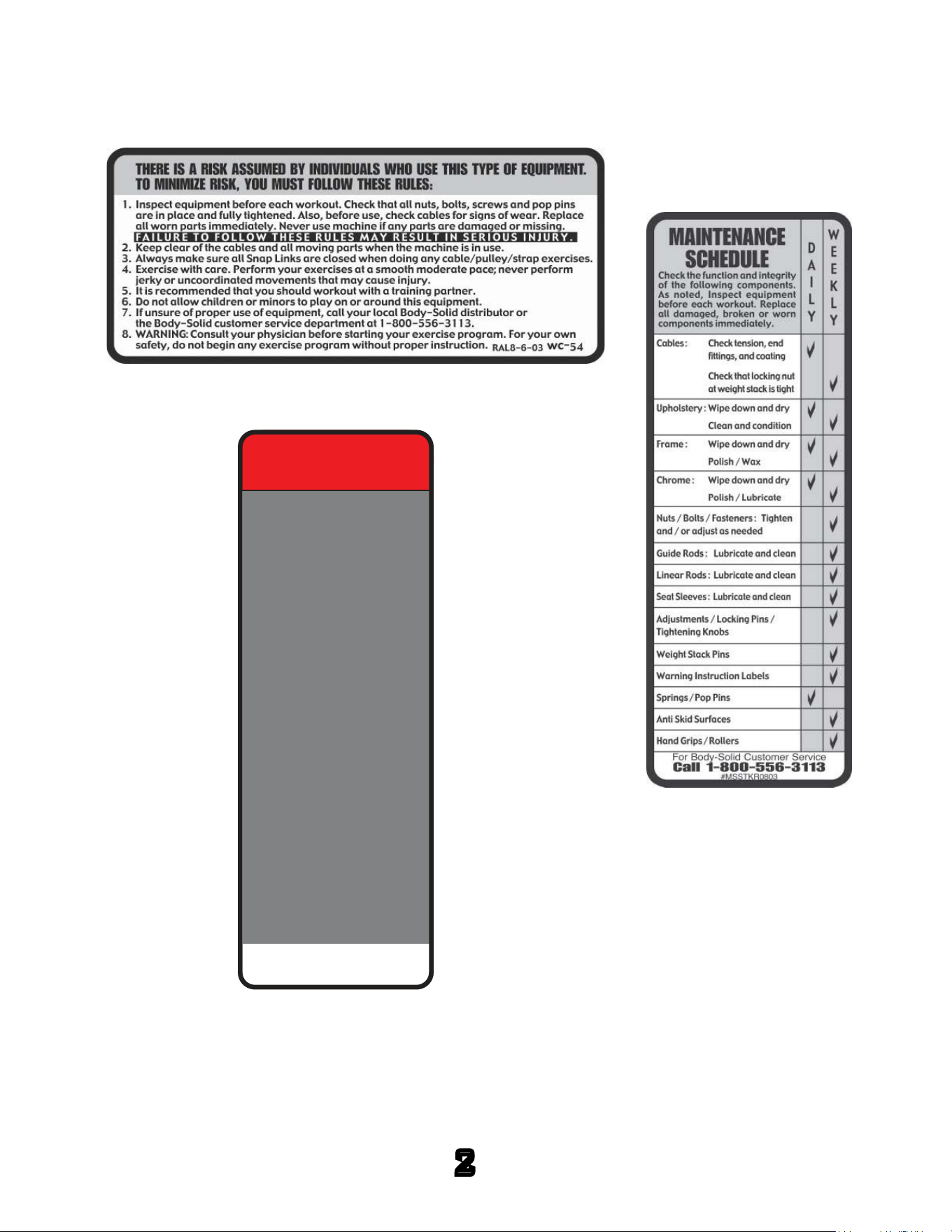
5
↑
YOUR S/N # CAN
BE FOUND HERE

PPR1000
PART LIST
6
Part #
A
B
C
D
E
F
G
H
J
K
L
M
N
1
2
3
4
5
6
7
8
9
QTY
2
4
8
1
1
1
2
6
2
1
1
2
2
32
8
64
32
2
8
2
2
2
DESCRIPTION
BASE FRAME
UPRIGHT
STEEL BRACKET
FOOT PLATE
CHIN UP BAR
REAR CROSSBAR
SIDE CROSSBAR
SHORT STEEL BRACKET
LONG STEEL BRACKET
RIGHT J CUP
LEFT J CUP
PIN
PIPE
M12x80mm HEX HEAD BOLT
M5X10mm FLAT HEAD CAP SCREW
M12 WASHER
M12 NYLON LOCKNUT
END CAP
PROTECTIVE FILM
PLASTIC PAD, 90X46mm
PLASTIC PAD, 46X46mm
QUICK RELEASE PIN
PPR1000
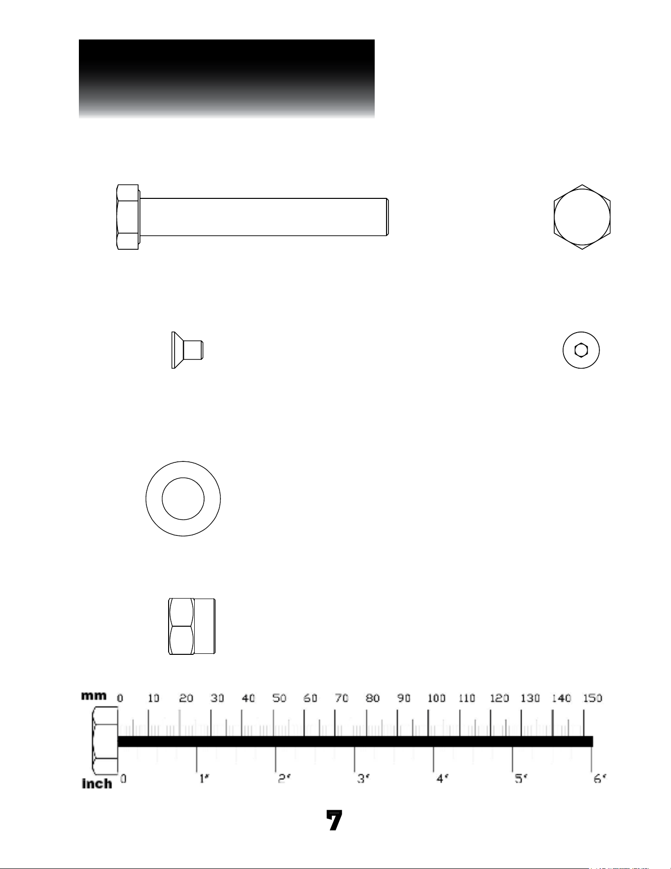
HARDWARE ILLUSTRATION
7
Part #3 M12 WASHER QTY. 64
Part #2 M5X10mm FLAT HEAD CAP SCREW QTY. 8
Part #1 M12x80mm hex head bolt QTY. 32
Part #4 M12 NYLON LOCKNUT QTY. 32

PPR1000
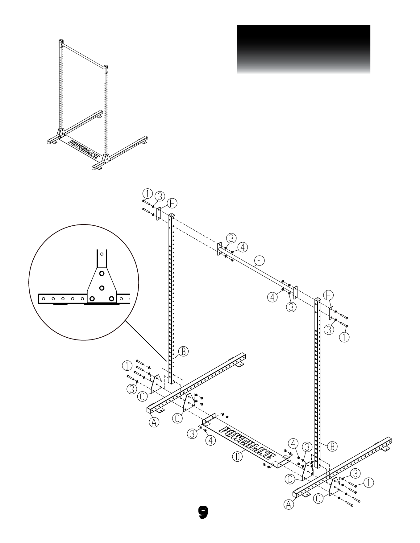
STEP 1
BE CAREFUL TO ASSEMBLE ALL COMPONENTS
IN THE SEQUENCE THAT THEY ARE PRESENTED.
NOTE:
finger tighten all hardware in this step. DO NOT wrench tighten
until the last step. some components may be pre-assembled.
nylon lock nuts will not fully screw onto bolts, must wrench tighten.
1A. attach Base Frames (A), Foot Plate (D) and Steel
Brackets (C) together using:
4 - (#1) m12x80mm hex head bolt
8 - (#3) m12 flat washer
4 - (#4) m12 nylon lock nut
NOTE #1:
Please refer to the drawing for correct bolt hole
locations. The bolt holes are 6th & 8th holes from the
closed end of the Base Frame.
1B. Attach uprights (B) to Steel Brackets (C) using:
4 - (#1) m12x80mm hex head bolt
8 - (#3) m12 flat washer
4 - (#4) m12 nylon lock nut
1C. Attach Chin Up Bar (E) to uprights (B) using:
4 - (#1) m12x80mm hex head bolt
8 - (#3) m12 flat washer
4 - (#4) m12 nylon lock nut
2 - (H) short steel Bracket
NOTE #2:
It is recommedated to install the equipment with at
least two persons.
8
PPR1000
STEP 1
9
above shows step 1 assembled
and completed

PPR1000
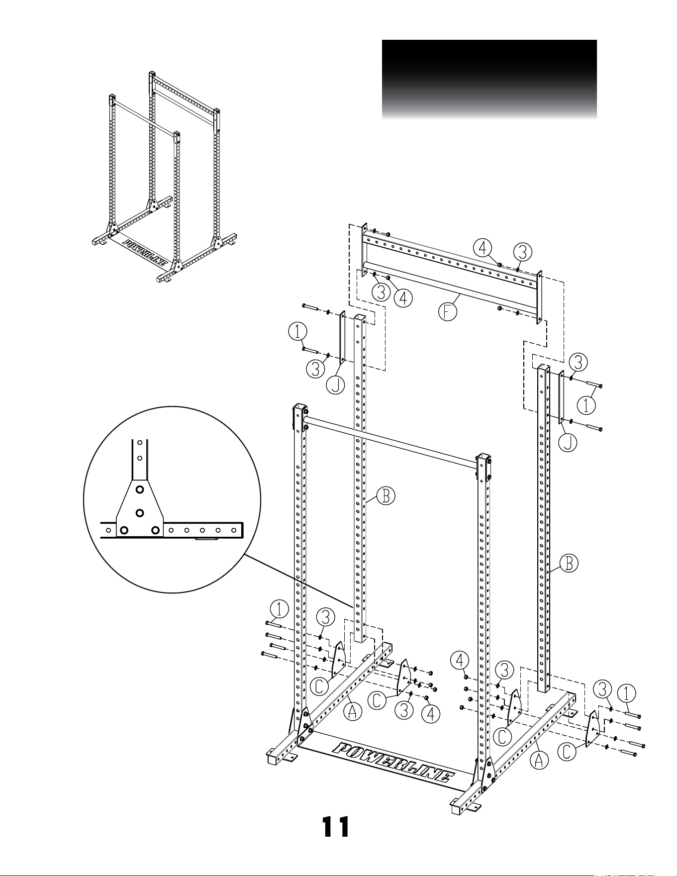
STEP 2
BE CAREFUL TO ASSEMBLE ALL COMPONENTS
IN THE SEQUENCE THAT THEY ARE PRESENTED.
NOTE:
finger tighten all hardware in this step. DO NOT wrench tighten
until the last step. some components may be pre-assembled.
nylon lock nuts will not fully screw onto bolts, must wrench tighten.
2A. attach Steel Brackets (C) to Base Frames (A) using:
4 - (#1) m12x80mm hex head bolt
8 - (#3) m12 flat washer
4 - (#4) m12 nylon lock nut
NOTE:
Please refer to the drawing for correct bolt hole
locations. The bolt holes are 6th & 8th holes from the
open end of the Base Frame.
2B. Attach uprights (B) to Steel Brackets (C) using:
4 - (#1) m12x80mm hex head bolt
8 - (#3) m12 flat washer
4 - (#4) m12 nylon lock nut
2C. Attach Rear Crossbar (F) to uprights (B) using:
4 - (#1) m12x80mm hex head bolt
8 - (#3) m12 flat washer
4 - (#4) m12 nylon lock nut
2 - (J) long steel Bracket
10
PPR1000
STEP 2
11
above shows step 2 assembled
and completed

PPR1000
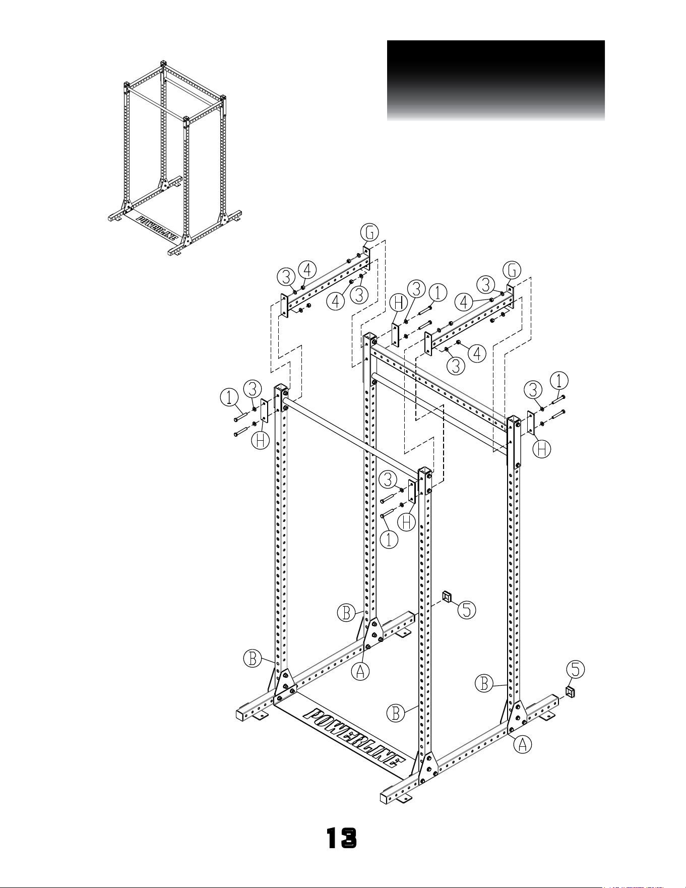
STEP 3
BE CAREFUL TO ASSEMBLE ALL COMPONENTS
IN THE SEQUENCE THAT THEY ARE PRESENTED.
NOTE:
finger tighten all hardware FIRST in this step. wrench tighten all
hardware at the END of step 3A. some components may be pre-assembled.
nylon lock nuts will not fully screw onto bolts, must wrench tighten.
3A. Attach Side Crossbars (G) to uprights (B) using:
8 - (#1) m12x80mm hex head bolt
16 - (#3) m12 flat washer
8 - (#4) m12 nylon lock nut
4 - (H) short steel Bracket
3B. Insert End Caps (#5) onto the open ends of Base
Frames (A).
12
PPR1000
STEP 3
13
above shows step 3 assembled
and completed

PPR1000
STEP 4
BE CAREFUL TO ASSEMBLE ALL COMPONENTS
IN THE SEQUENCE THAT THEY ARE PRESENTED.
NOTE:
some components may be pre-assembled. nylon lock nuts will not fully
screw onto bolts, must wrench tighten.
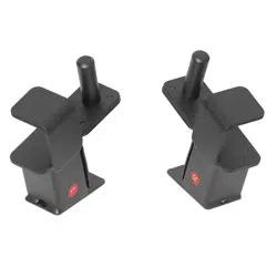
Adjustable J Cups and Pipe & Pin Safeties
4A. Attach Left & Right J Cups (K & L) to Uprights (B).
4B. Hold Pipes (N) between Uprights (B) and insert Pins (M)
into the Pipes (N) and Uprights (B).
4C. Insert the Quick Release Pins (#9) into tht end of Pins (M).
NOTE:
SECURELY anchor the machine to the floor using the
anchor holes provided. Please consult a professional
contractor for the actual anchoring of the machine.
14
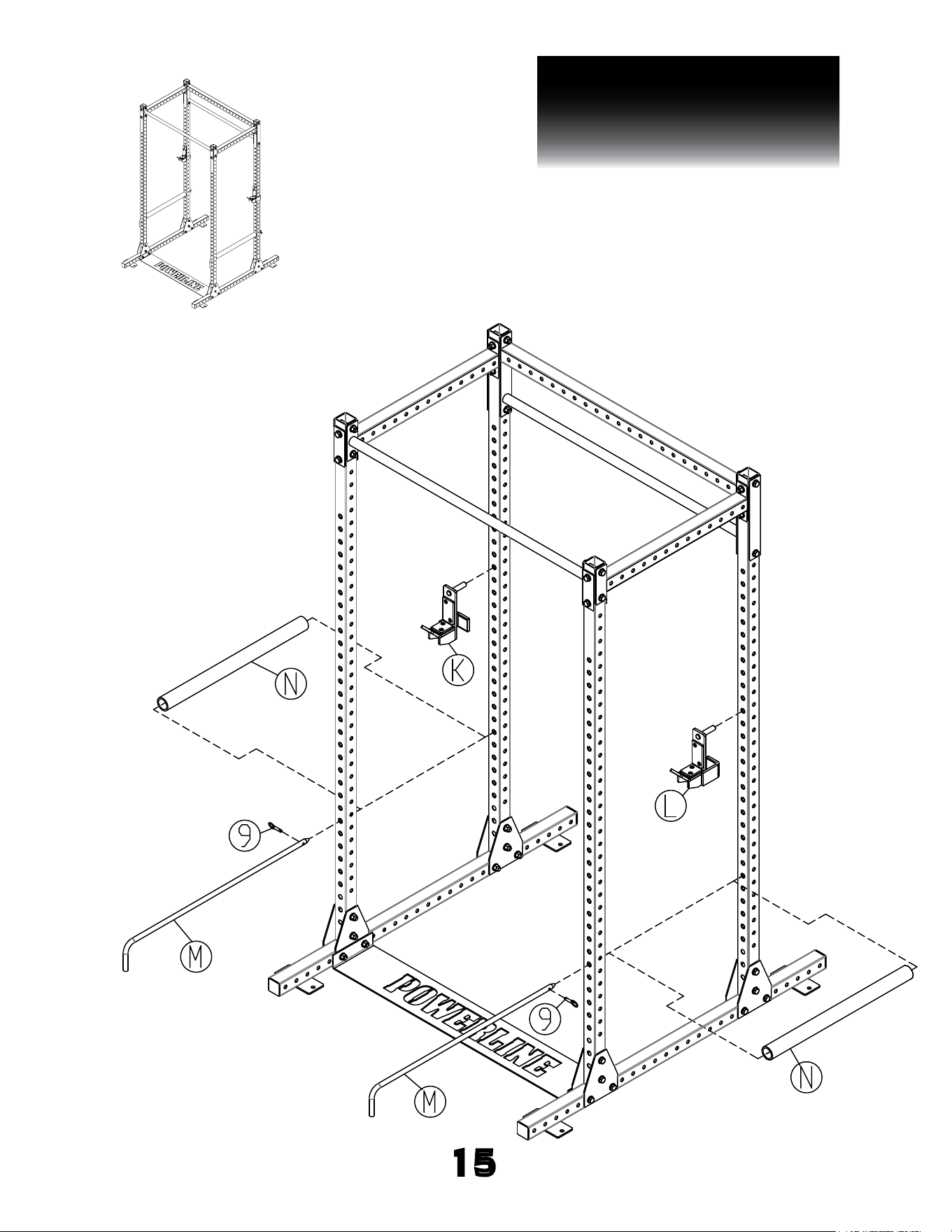
PPR1000
STEP 4
15
above shows step 4 assembled
and completed

16
PPR1000
NOTE
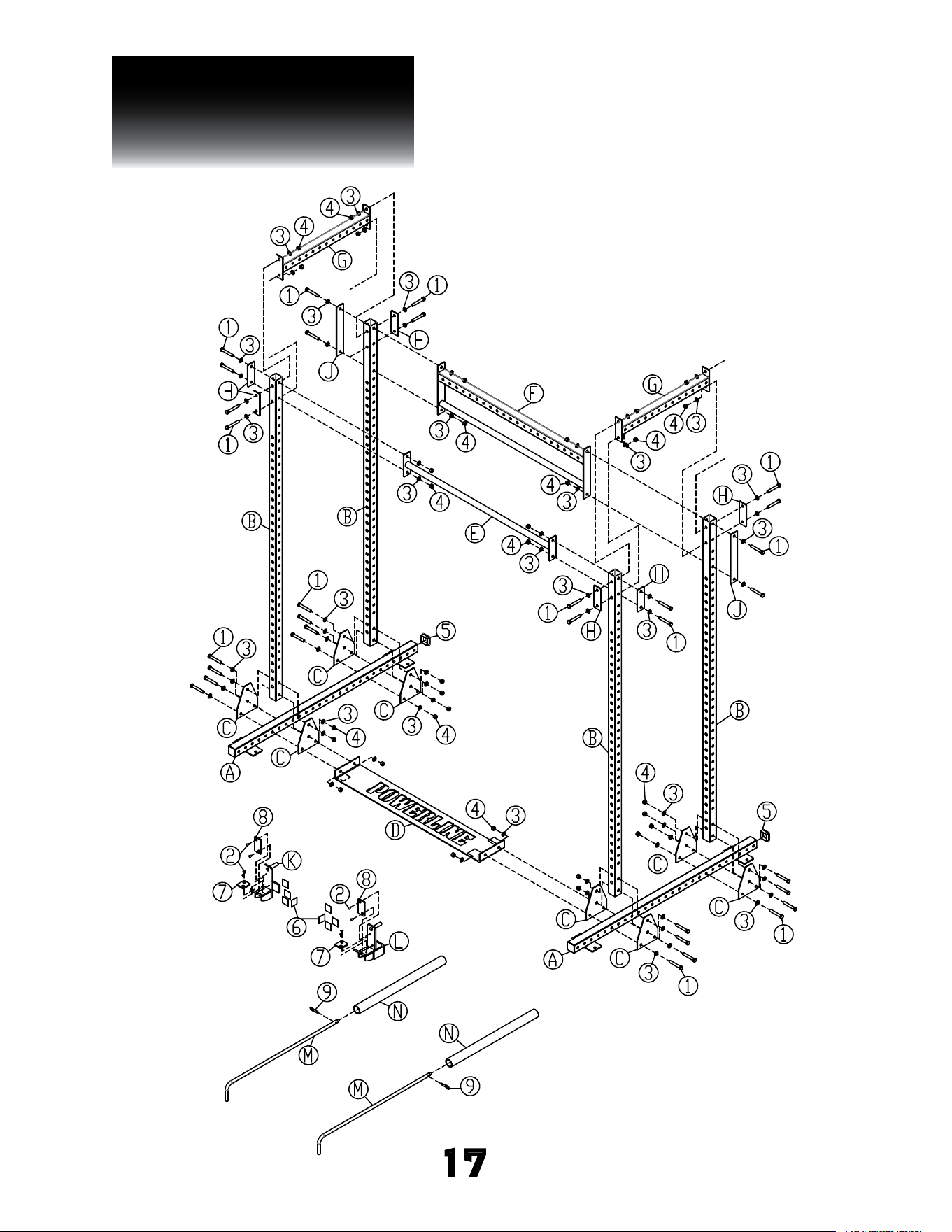
PPR1000
EXPLODED VIEW
17

PPR1000
S/N # 014725-��-��-����-����
please write your serial number in the boxes below
1900 S. Des Plaines Ave.
Forest Park, IL 60130
Phone:(708)427-3555
Fax:(708)427-3556
Hours: M-F 8:30 - 5:00 CST