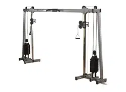
BFCCO10B
Owner’s Manual
V. BFCCO10B-20241118
2
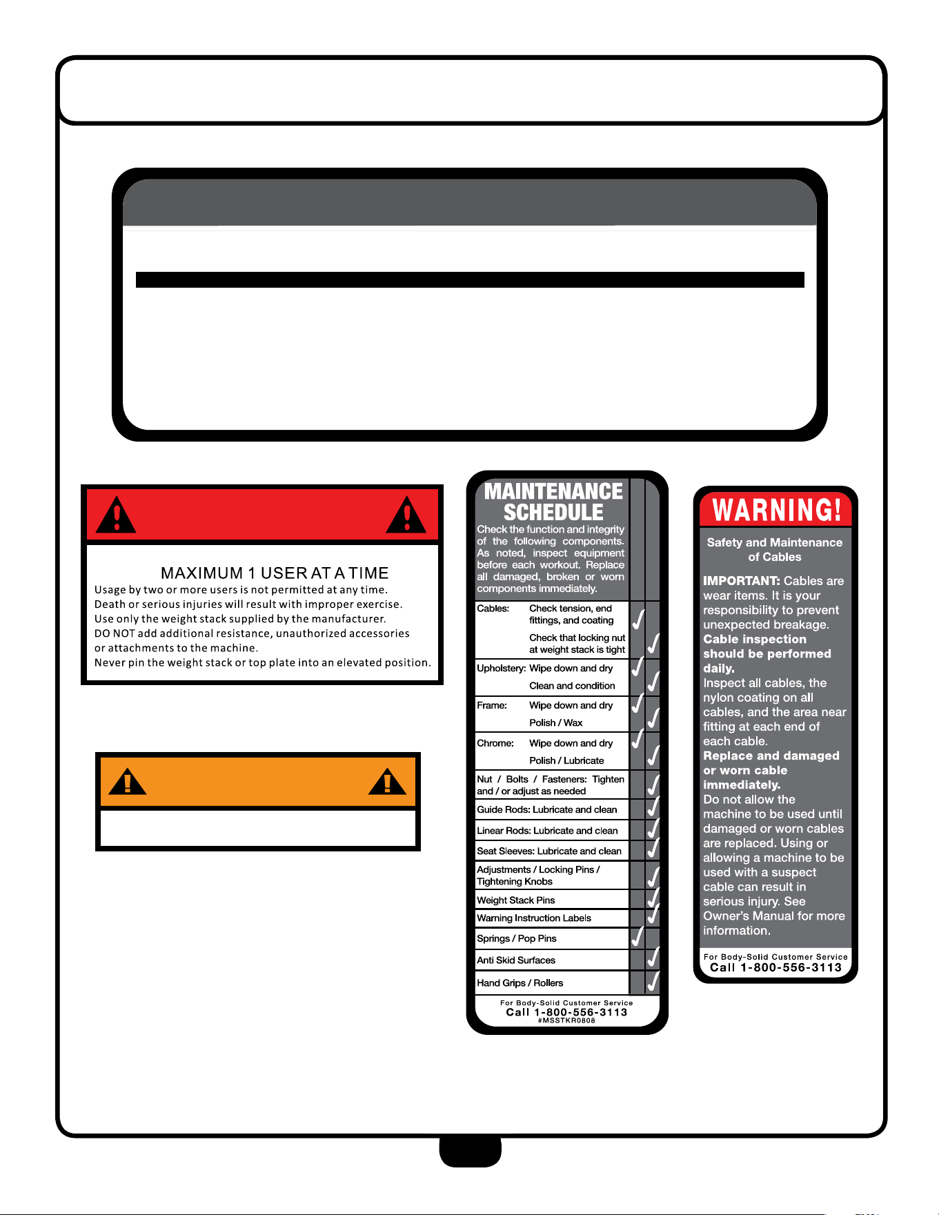
warning, saFety, & MaintenanCe
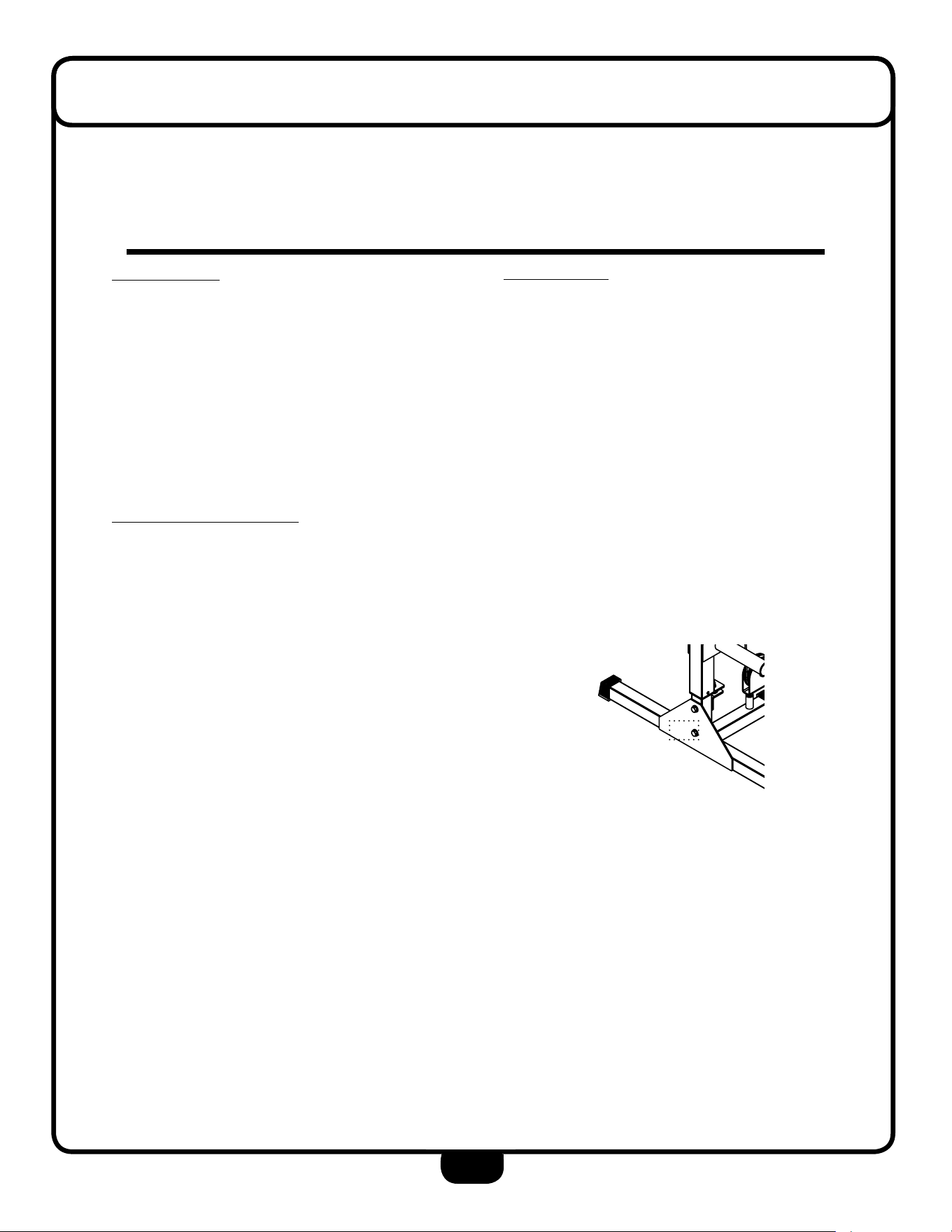
Adjust
Cable
Here
ALWAYS make sure pop
pin plunger is in place
and lock it by turning
clockwise until tight.
THERE IS A RISK ASSUMED BY INDIVIDUALS WHO USE THIS TYPE OF EQUIPMENT.
TO MINIMIZE RISK, YOU MUST FOLLOW THESE RULES:
Inspect equipment before each workout. Check that all nuts, bolts, screws and pop pins
are in place and fully tightened. Also, before use, check cables for sign of wear. Replace all
worn parts immediately. Never use machine if any parts are damaged or missing.
FAILURE TO FOLLOW THESE RULES MAY RESULT IN SERIOUS INJURY.
Keep clear of the cables and all moving parts when machine is in use.
Always make sure all Snap Links are closed when doing cable/pulley/strap exercises.
Exercise with care. Perform your exercises at a smooth moderate pace; never perform jerky
or uncoordinated movements that may cause injury.
It is recommended that you workout with a training partner.
Do not allow children or minors to play on or around this equipment.
If unsure of proper use of equipment, call your local Body-Solid distributor or the
Body-Solid customer service center at 1-800-556-3113.
WARNING: Consult your physician before starting your exercise program. For your own
safety, do not begin any exercise program without proper instruction.
THERE IS A RISK ASSUMED BY INDIVIDUALS WHO USE THIS TYPE OF EQUIPMENT.
TO MINIMIZE RISK, YOU MUST FOLLOW THESE RULES:
Inspect equipment before each workout. Check that all nuts, bolts, screws and pop pins
are in place and fully tightened. Also, before use, check cables for sign of wear. Replace all
worn parts immediately. Never use machine if any parts are damaged or missing.
FAILURE TO FOLLOW THESE RULES MAY RESULT IN SERIOUS INJURY.
Keep clear of the cables and all moving parts when machine is in use.
Always make sure all Snap Links are closed when doing cable/pulley/strap exercises.
Exercise with care. Perform your exercises at a smooth moderate pace; never perform jerky
or uncoordinated movements that may cause injury.
It is recommended that you workout with a training partner.
Do not allow children or minors to play on or around this equipment.
If unsure of proper use of equipment, call your local SteelFlex distributor or the SteelFlex
customer service center at 1-800-556-3113.
WARNING: Consult your physician before starting your exercise program. For your own
safety, do not begin any exercise program without proper instruction.
WARNING!
PINCH POINTS
Be alert! Keep hands
and fingers clear of
moving parts.
WARNING!
SafetyÊandÊMaintenance
ofÊCables
IMPORTANT:ÊCables are
wear items. It is your
responsibility to prevent
unexpected breakage.
Cable inspection
should be performed
daily.
Inspect all cables, the
nylon coating on all
cables, and the area near
fitting at each end of
each cable.
Replace and damaged
or worn cable
immediately.
Do not allow the
machine to be used until
damaged or worn cables
are replaced. Using or
allowing a machine to be
used with a suspect
cable can result in
serious injury. See
Owner’s Manual for more
information.
For Steelflex Customer Service
CallÊ1-800-556-3113
WARNING!
SafetyÊandÊMaintenance
ofÊCables
IMPORTANT:ÊCables are
wear items. It is your
responsibility to prevent
unexpected breakage.
Cable inspection
should be performed
daily.
Inspect all cables, the
nylon coating on all
cables, and the area near
fitting at each end of
each cable.
Replace and damaged
or worn cable
immediately.
Do not allow the
machine to be used until
damaged or worn cables
are replaced. Using or
allowing a machine to be
used with a suspect
cable can result in
serious injury. See
Owner’s Manual for more
information.
For Best Fitness Customer Service
CallÊ1-800-556-3113
WARNING!
SafetyÊandÊMaintenance
ofÊCables
IMPORTANT:ÊCables are
wear items. It is your
responsibility to prevent
unexpected breakage.
Cable inspection
should be performed
daily.
Inspect all cables, the
nylon coating on all
cables, and the area near
fitting at each end of
each cable.
Replace and damaged
or worn cable
immediately.
Do not allow the
machine to be used until
damaged or worn cables
are replaced. Using or
allowing a machine to be
used with a suspect
cable can result in
serious injury. See
Owner’s Manual for more
information.
For Body-Solid Customer Service
CallÊ1-800-556-3113
MAINTENANCE
SCHEDULE
Check the function and integrity
of the following components.
As noted, inspect equipment
before each workout. Replace
all damaged, broken or worn
components immediately.
Cables: Check tension, end
fittings, and coating
Check that locking nut
at weight stack is tight
Upholstery: Wipe down and dry
Clean and condition
Frame: Wipe down and dry
Polish / Wax
Chrome: Wipe down and dry
Polish / Lubricate
Nut / Bolts / Fasteners: Tighten
and / or adjust as needed
Guide Rods: Lubricate and clean
Linear Rods: Lubricate and clean
Seat Sleeves: Lubricate and clean
Weight Stack Pins
Warning Instruction Labels
Springs / Pop Pins
Anti Skid Surfaces
Hand Grips / Rollers
For Body-Solid Customer Service
CallÊ1-800-556-3113
#MSSTKR0808
Adjustments / Locking Pins /
Tightening Knobs
SteelFlex
THERE IS A RISK ASSUMED BY INDIVIDUALS WHO USE THIS TYPE OF EQUIPMENT.
TO MINIMIZE RISK, YOU MUST FOLLOW THESE RULES:
Inspect equipment before each workout. Check that all nuts, bolts, screws and pop pins
are in place and fully tightened. Also, before use, check cables for sign of wear. Replace all
worn parts immediately. Never use machine if any parts are damaged or missing.
FAILURE TO FOLLOW THESE RULES MAY RESULT IN SERIOUS INJURY.
Keep clear of the cables and all moving parts when machine is in use.
Always make sure all Snap Links are closed when doing cable/pulley/strap exercises.
Exercise with care. Perform your exercises at a smooth moderate pace; never perform jerky
or uncoordinated movements that may cause injury.
It is recommended that you workout with a training partner.
Do not allow children or minors to play on or around this equipment.
If unsure of proper use of equipment, call your local Best Fitness distributor or the Best
Fitness customer service center at 1-800-556-3113.
WARNING: Consult your physician before starting your exercise program. For your own
safety, do not begin any exercise program without proper instruction.
Best Fitness
DO nOt reMOVe warning laBels FrOM Manual Or MaCHine
DANGER
WARNING
DO NOT HANG ANYTHING ON THE CROSSBEAM

3
taBle OF COntents
• saFety instruCtiOns ............................ Page 4
• PreParatiOn ... ............ ............................ Page 5
• HarDware list ...... ...... ............................ Page 6
• HarDware illustratiOn ............................ Page 8
• asseMBly instruCtiOns ............................ Page 10
• eXPlODeD View ...... ...... ............................ Page 20
• COntaCt Page ...... ...... ............................ Page 22
4
iMPOrtant saFety instruCtiOns
Before beginning any tness program, you should obtain a complete physical examination from your physician.
Il est conseille de subir un examen medical complet avant d’entreprendre tout programme d’exercise. Si vous
avez des etourdissements ou des faiblesses, arretez les exercices immediatement.
Antes de comenzar cualquier programma de ejercicios, deberias tener un examen sico con su doctor.
When using exercise equipment, you
should always take basic precautions,
including the following:
• Read all instruction befor using the BFCCO10B.
These instructions are writeen to ensure you
safety and to the protect the unit.
• Donotremoveanysafetylabelsfromthe
machine.
• Do not allow children on or near the equipment.
• Ust the equipment only for its intended purpose
as described in this guide. Do not use accessory
attachments that are not recommended by the
manufacturer. Such attachments might cause
injuries.
• Wear proper exercise clothing and shoes for you
workout, no loose clothing.
• Keep hands, limbs, loose clothing, and long hair
well out fo the way of all moving parts.
• Use care when getting on or o the unit.
• Do not overexert yourself to work to exhaustion.
• If you feel any pain or abnormal symptoms,
stop your workout immediately and consult your
physician
• Never operate the unit when it has been dropped
or damaged. Return the equipment to a service
center for examination and repair.
• Never drop or insert objects into any opening in
the equipment.
• Always check the unit before each use. Make
sure that all fasteners are secure and in good
working condition.
• Do not use the equipment outdoors or near water.
Personal Safety During Assembly
• Before beginning assembly, please take the time
to read the instructions thoroughly.
• Read each step in the assembly instructions and
follow the steps in sequence. Do no skip ahead.
If you skip ahead, you may learn later that you
have to disassemble components and that you
may have damaged the equipment.
• Assemble and operate the BFCCO10B on a sol-
id, level surface. Locate the unit a few feet from
the walls or furniture to provide easy access.
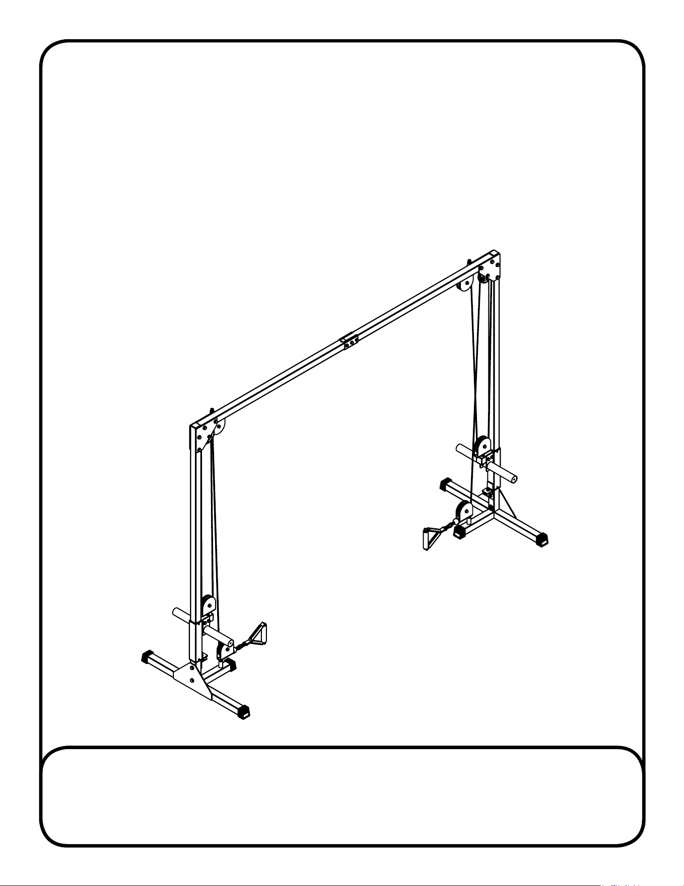
The BFCCO10B is designed for your enjoyment. By
following these precautions and using common
sense, you will have many safe and pleasurable hours
of healthful exercise with your Best Fitness
BFCCO10BCABLECROSSOVERMACHINE.
After assembly, you should check all functions to
ensure correct operation. If you experience problems,
rst recheck the assembly instructions to locate any
possible errors made during assembly. If you are
unable to correct the problem, call the dealer from
whom you purchased the machine or call
1-800-556-3113 for the dealer nearest you.
Obtaining Service
Please use this Owner’s Manual to make sure that all
parts have been included in your shipment. When
ordering parts, you must use the part number and
description from this Owner’s Manual. Use only
Best Fitness replacement parts when servicing this
machine. Failure to do so will void your warranty and
could result in personal injury.
For information about product operation or service,
go to www.besttness.com or contact an authorized
Best Fitness dealer or a Best Fitness factory-au-
thorized service company or contact Best Fitness
customer service at one of the following:
TollFree:1-800-556-3113
Phone: 1-708-427-3555
Fax: 1-708-427-3556
Hours: M-F8:30-5:00CST
E-Mail: [email protected]
Orwriteto:BestFitness
ServiceDepartment
1900S.DesPlainesAve.
ForestPark,IL60130USA
Retain this Owner’s Manual for future
reference. If you need to order replacement
parts please be prepared to provide the
following information when contacting us so
that we can assist you better.
1. Model Number
2. Place of Purchase
3. Serial Number (S/N)
4. Part # and Description
5
PreParatiOn
Best Fitness continually seeks ways to improve the performance, specications and product manuals in order to
ensure that only superior products are released from our factories. Please take the time to carefully read through this
manual thoroughly. Instructions contained in this document are not intended to cover all details or variations possible
with Best Fitness equipment, or to cover every contingency that may be met in conjunction with installation, operation,
maintenance or troubleshooting of the equipment. Even though we have prepared this manual with extreme care,
neither the publisher nor the author can accept responsibility for any errors in, or omission from, the information
given. Should additional information be required, or should situations arise that are not covered by this manual, the
matter should be directed to your local Best Fitness representative, or the Service Department at
Body-Solid Inc. in Forest Park, Illinois.
Any Questions?
Call (800) 556-3113
Thank you for purchasing the BFCCO10B. This machine is part of the Best Fitness line of quality strength training
machines, which lets you target specic muscle groups to achieve better muscle tone and overall body
conditioning. To maximize your use of the equipment please study this Owner’s Manual thoroughly.
Required Tools
The basic tools that you must obtain before assembling
the BFCCO10B include but are not limited to:
• Metric Allen Key Set
• Standard Allen Key Set
• Standard Wrench Set
• Metric Wrench Set
• Adjustable Wrench
• Screwdriver (standard and/or phillips)
Installation Requirements
Follow these installation requirements when assembling
the BFCCO10B:
Set up the BFCCO10B on a solid, at surface. A smooth,
at surface under the machine helps keep it level. A
level machine has fewer malfunctions.
Provide ample space around the machine. Open
space around the machine allows for easier access.
Insert all bolts in the same direction. For aesthetic
purposes, insert all bolts in the same direction unless
specied (in text or illustrations) to do otherwise.
Leave room for adjustments. Tighten fasteners such as
bolts, nuts, and screws so the unit is stable, but leave
room for adjustments. Do not fully tighten fasteners
until instructed in the assembly steps to do so.
Filloutandmailthewarrantycard.
Assembly Tips
Read all “Notes” on each page before beginning each
step.
While you may be able to assemble the BFCCO10B us-
ing the illustrations only, important safety notes and other
tips are included in the text.
Some pieces may have extra holes that you will not use.
Use only those holes indicated in the instructions and
illustrations.
NOTE: With so many assembled parts, proper
alignment and adjustment is critical. While
tightening the nuts and bolts, be sure to leave
room for adjustments.
NOTE: The bottles that are marked “Poison” is your
touch up paint. Keep away from children.
CAUTION:Obtain assistance! If you feel like you can’t
assemble the BFCCO10B by yourself then
do
not attempt to do so as this could result in
injury. Review the installation requirements
before proceeding with the following steps.
Your S/N# can
be found here
↑

6
BFCCO10B - Part list
Part#
a
B
C
e
F
H
J
K
l
M
n
1
2
3
4
5
6
7
8
9
10
Part numbers are required when ordering parts.
DesCriPtiOn
uPrigHt
Base FraMe
l BraCKet
Pulley BraCKet
MiD Pulley BraCKet
suPPOrt BraCKet
CrOssBeaM a
CrOssBeaM B
CrOssBeaM BraCKet
sliDing Carriage
weigHt HOrn
M12x80mm HeX HeaD BOlt
M12x75mm HeX HeaD BOlt
M10x75mm HeX HeaD BOlt
M10x50mm HeX HeaD BOlt
M10x25mm ButtOn HeaD CaP sCrew
M12 wasHer
M10 wasHer
M12 large wasHer
M12 nylOn lOCK nut
M10 nylOn lOCK nut
Quantity
2 PCs.
2 PCs.
2 PCs.
4 PCs.
2 PCs.
4 PCs.
1 PCs.
1 PCs.
2 PCs.
2 PCs.
2 PCs.
10 PCs.
2 PCs.
9 PCs.
6 PCs.
2 PCs.
34 PCs.
32 PCs
2 PCs
18 PCs
17 PCs

7
BFCCO10B - Part list
Part#
11
12
13
14
15
16
17
18
19
20
21
Part numbers are required when ordering parts.
DesCriPtiOn
PlastiC BusHing
FOOt CaP
Metal BusHing
ruBBer stOPPer
PlastiC enD CaP
CaBle
Pulley
snaP linK
straP HanDle
Metal sPaCer
PlastiC tOP CaP
Quantity
4 PCs
6 PCs
12 PCs
2 PCs
2 PCs.
2 PCs.
8 PCs.
2 PCs.
2 PCs.
2 PCs.
2 PCs
8
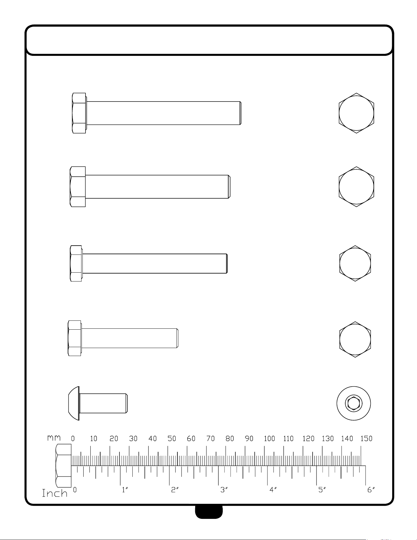
HarDware illustratiOn
Part #1 HeX HeaD BOlt M12x80mm Qty. 10
Part #2 HeX HeaD BOlt M12x75mm Qty. 2
Part #3 HeaD HeaD BOlt M10x75mm Qty. 9
Part #4 HeaD HeaD BOlt M10x50mm Qty. 6
Part #5 ButtOn HeaD CaP sCrew M10x25mm Qty. 2
9
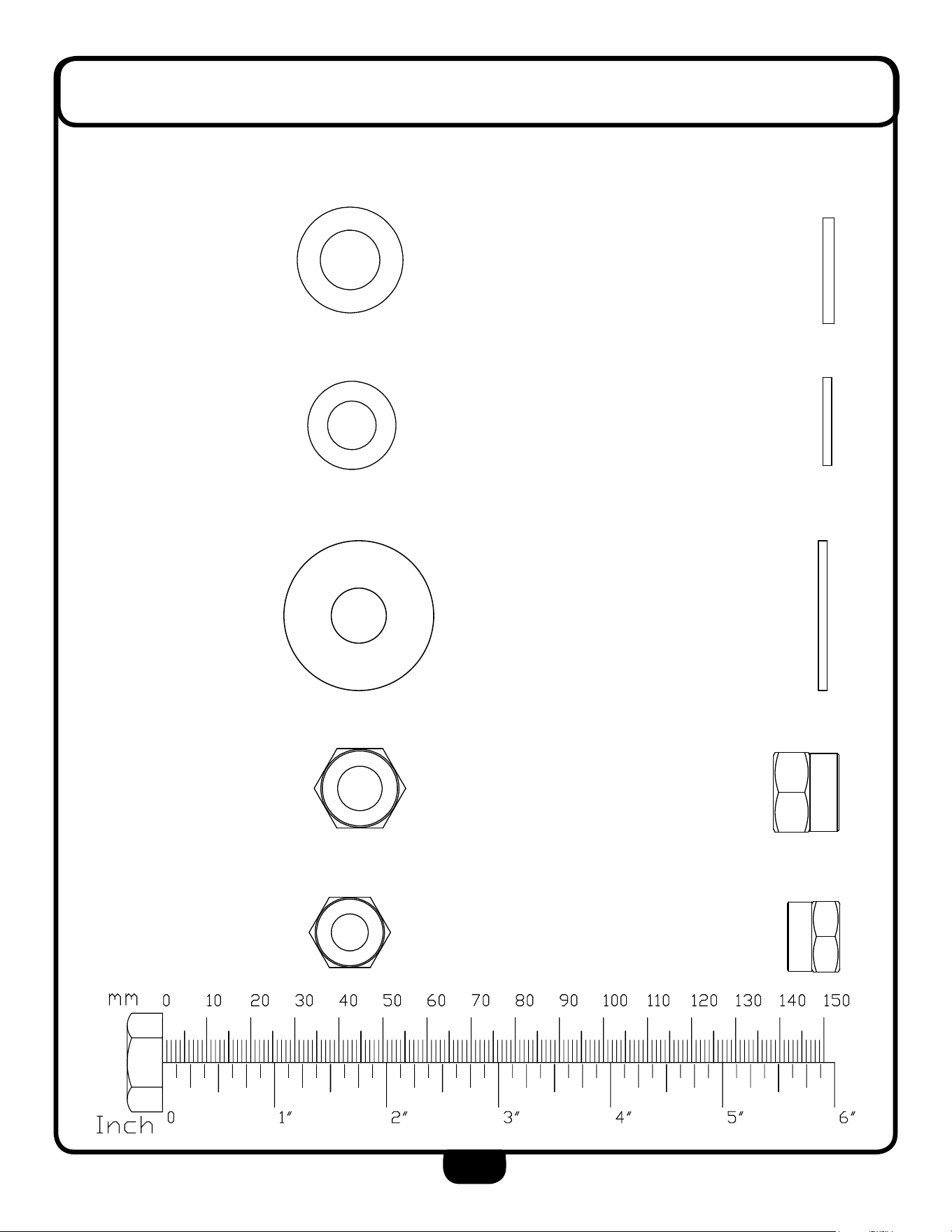
HarDware illustratiOn
Part #6 M12 wasHer Qty. 34
Part #7 M10 wasHer Qty. 32
Part #8 M12 large wasHer Qty. 2
Part #9 M12 nylOn lOCK nut Qty. 18
Part #10 M10 nylOn lOCK nut Qty. 17

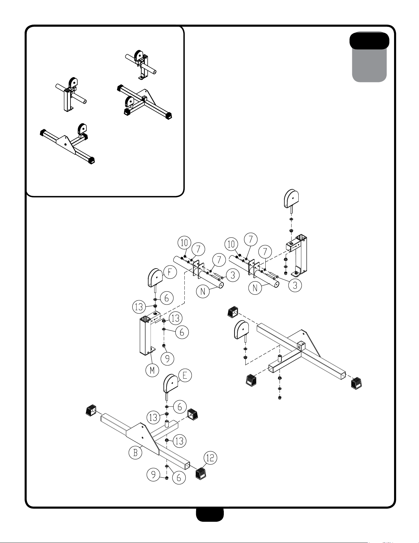
10
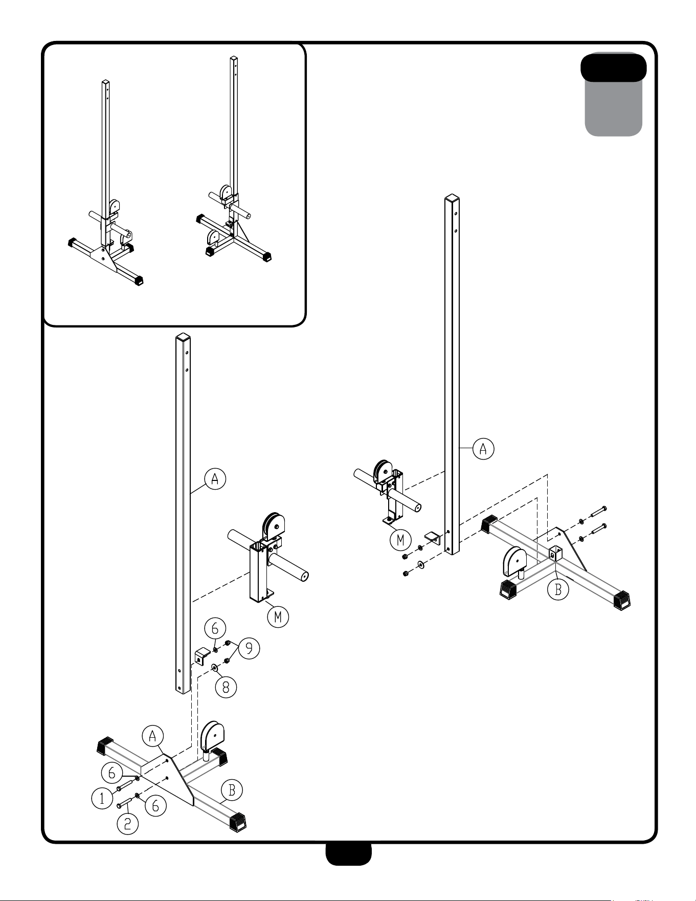
steP
1
Be careful to assemble all components
in the sequence they are presented.
nOte:
Finger tighten all hardware first. wrench tighten at the end of step 1D.
some components may be pre-assembled. nylon lock nuts will not fully
screw onto bolts, they must be wrench tighten to fully go on.
1a. attach Pulley Bracket (e) to Base Frame (B) using:
2 - (#6) M12 Flat washer
1 - (#9) M12 nylon lock nut
2 - (#13) Metal Bushing
1B. insert Foot Caps (#12) onto the Base Frame (B).
1C. attach Mid Pulley Bracket (F) to sliding Carriage (M) using:
2 - (#6) M12 Flat washer
1 - (#9) M12 nylon lock nut
2 - (#13) Metal Bushing
1D. attach weight Horn (n) to sliding Carriage (M) using:
2 - (#3) M10x75mm Hex Head Bolt
4 - (#7) M10 Flat washer
1 - (#10) M10 nylon lock nut
1e. repeat the previous steps (1a - 1D) on the other side of the
machine.
11
steP
1
above shows steP 1 assembled and completed.

12
steP
2
Be careful to assemble all components
in the sequence they are presented.
nOte:
Finger tighten all hardware first. some components may be pre-assembled.
2a. attach one upright (a) to Base Frame (B) using:
1 - (#1) M12x80mm Hex Head Bolt
1 - (#2) M12x75mm Hex Head Bolt
3 - (#6) M12 Flat washer
1 - (#8) M12 large washer
2 - (#9) M12 nylon lock nut
1 - (C) l Bracket
2B. insert sliding Carriage (M) onto upright (a):
2C. repeat the previous steps (2a & 2B) on the other side of the machine.
13
steP
2
above shows steP 2 assembled and completed.

14
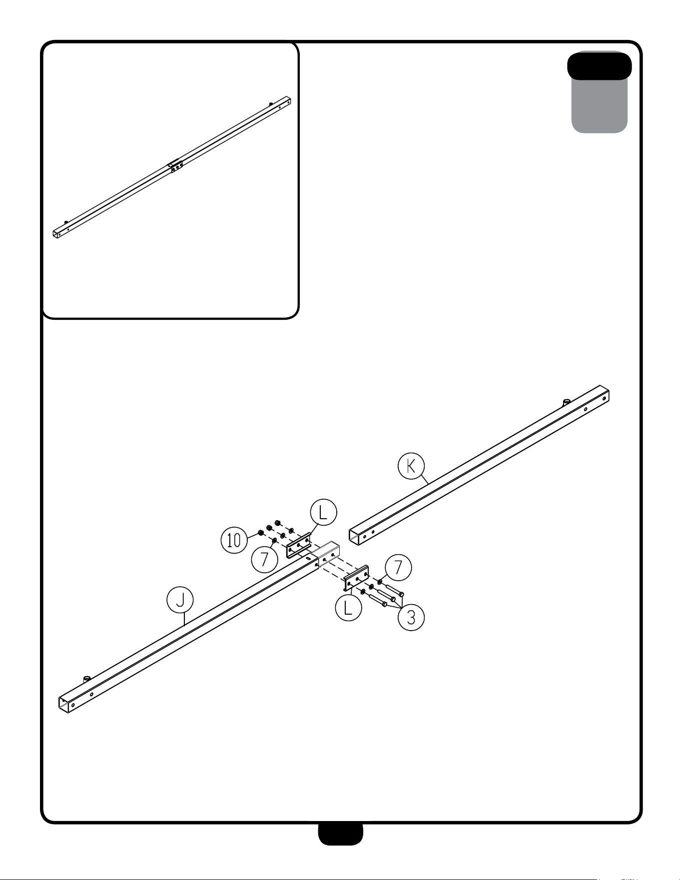
steP
3
Be careful to assemble all components
in the sequence they are presented.
nOte:
Finger tighten all hardware first. some components may be pre-assembled.
3a. attach Crossbeams (J & K) together using:
3 - (#3) M10x75mm Hex Head Bolt
6 - (#7) M10 Flat washer
3 - (#10) M10 nylon lock nut
2 - (l) Crossbeam Bracket
15
steP
3
above shows steP 3 assembled and completed.

16
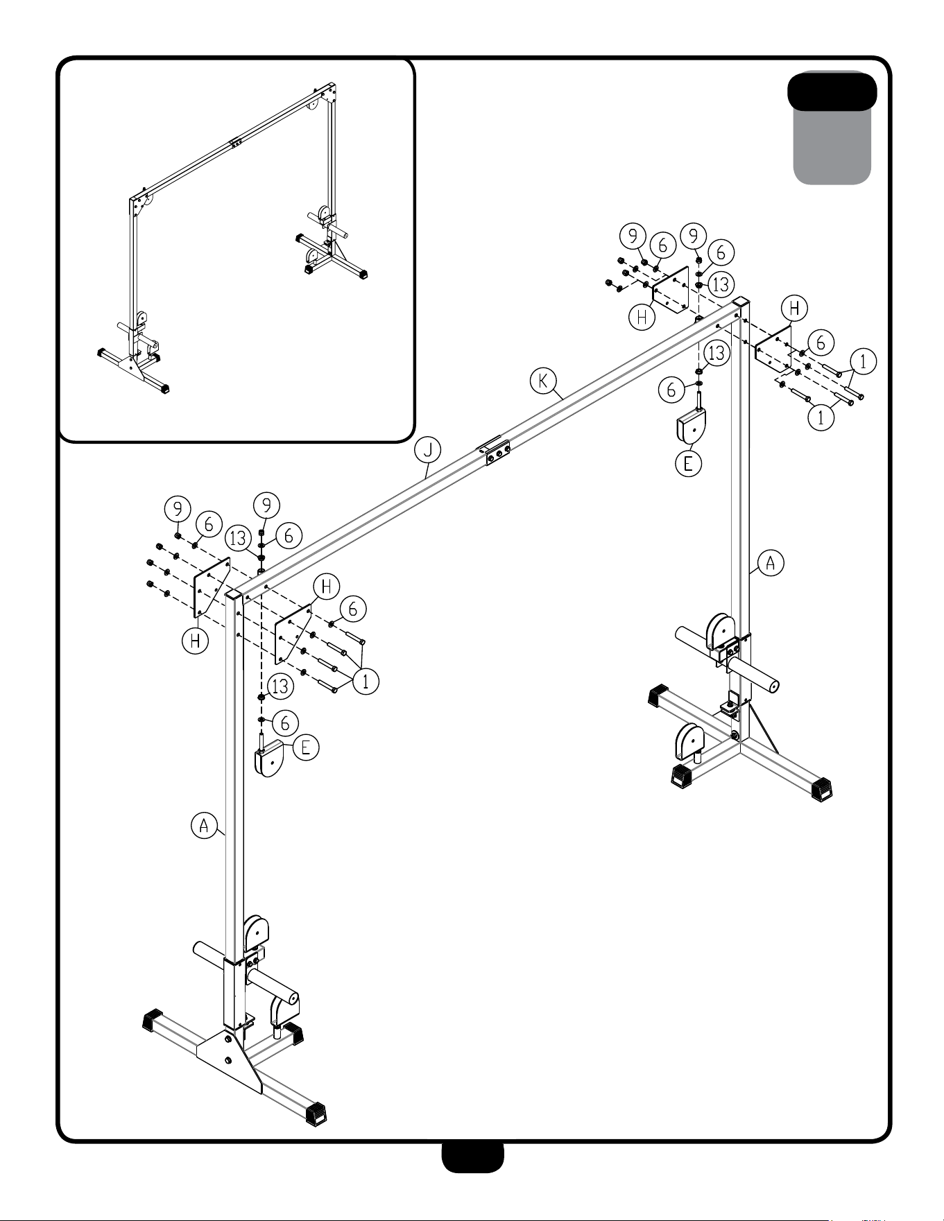
steP
4
Be careful to assemble all components
in the sequence they are presented.
nOte:
Finger tighten all hardware first. wrench tighten at the end of step 4B.
some components may be pre-assembled. nylon lock nuts will not fully
screw onto bolts, they must be wrench tighten to fully go on.
4a. attach Crossbeams (J & K) to uprights (a) using:
8 - (#1) M12x80mm Hex Head Bolt
16 - (#6) M12 Flat washer
8 - (#9) M12 nylon lock nut
4 - (H) support Bracket
4B. attach Pulley Brackets (e) to Crossbeams (J & K) using:
4 - (#6) M12 Flat washer
2 - (#9) M12 nylon lock nut
4 - (#13) Metal Bushing
17
steP
4
above shows steP 4 assembled and completed.

18
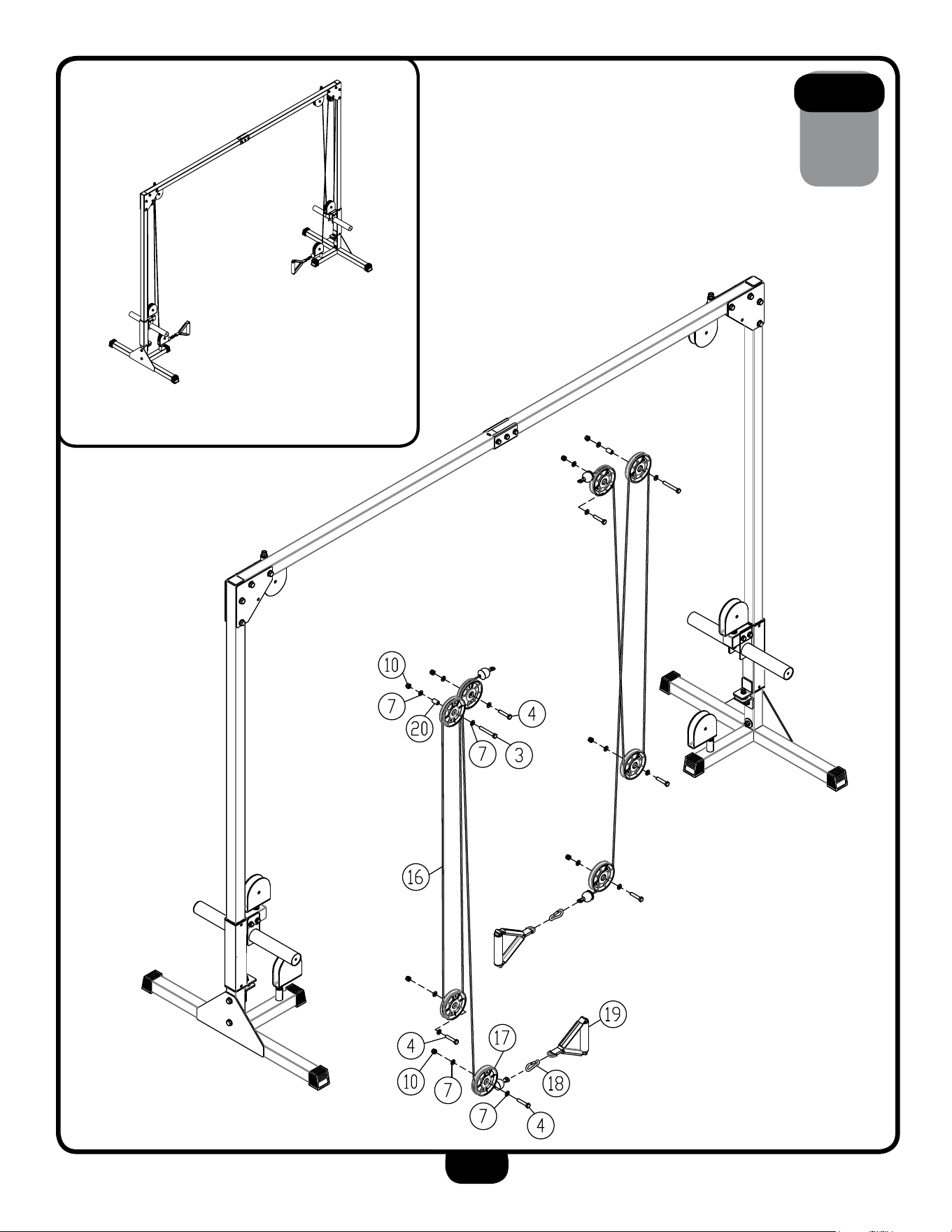
steP
5
Be careful to assemble all components
in the sequence they are presented.
nOte:
Finger tighten all hardware first. wrench tighten at the end of step 5C.
some components may be pre-assembled. nylon lock nuts will not fully
screw onto bolts, they must be wrench tighten to fully go on.
5a. route Cable (#16) and install 4 Pulleys (#17) on one side of the
machine as shown in step 5 using
3 - (#4) M10x50mm Hex Head Bolt
1 - (#3) M10x80mm Hex Head Bolt
8 - (#7) M10 Flat washer
4 - (#10) M10 nylon lock nut
1 - (#20) Metal spacer
5B. attach strap Handle (#19) to Cable (#16) using snap link (#18)
5C. repeat the previous steps (5a & 4B) on the other side of the machine.
19
steP
5
above shows steP 5 assembled and completed.
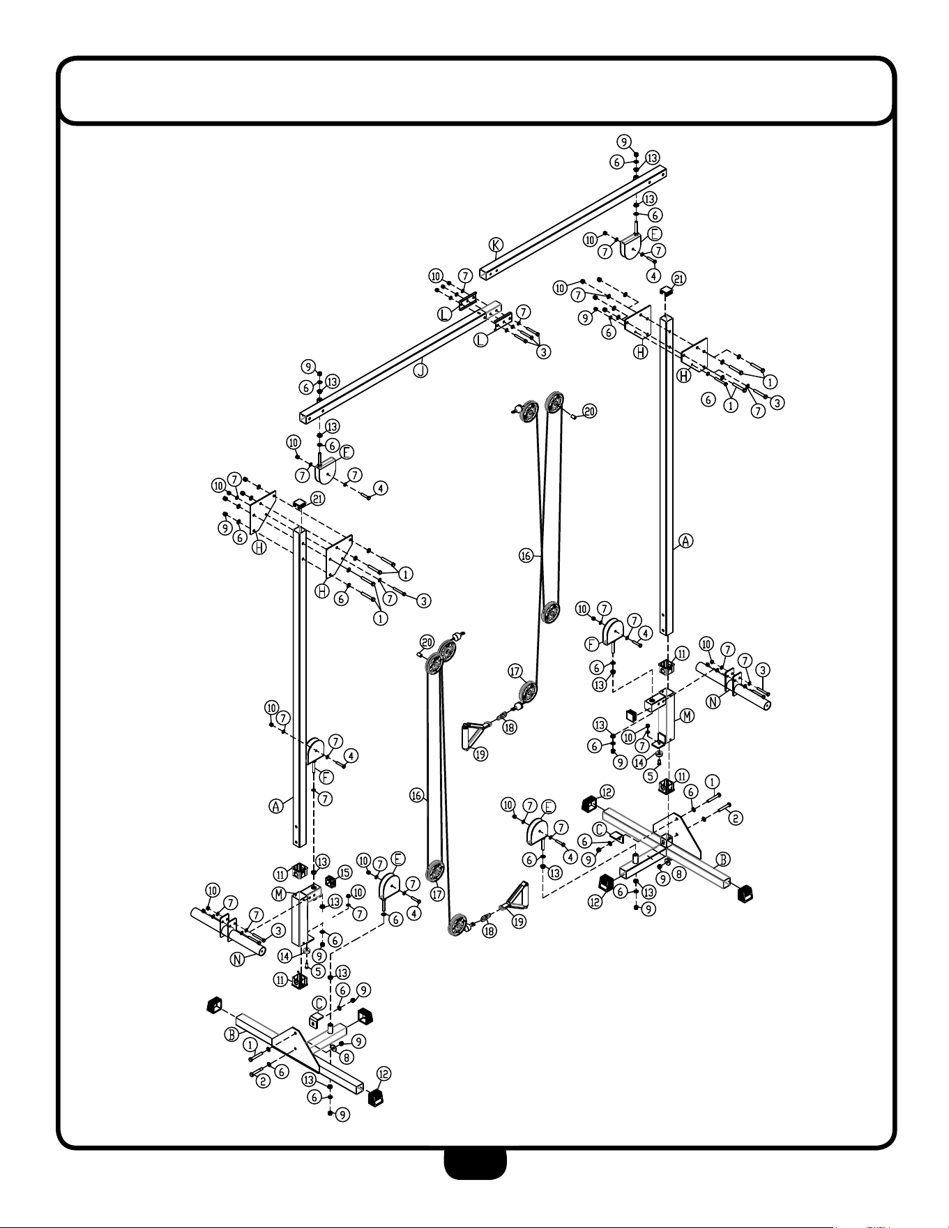
20
eXPlODeD View DiagraM

21
nOte

1900 S. Des Plaines Ave.
Forest Park, Il 60130
1 (800) 556-3113
Hours: M-F 8:30 - 5:00 CST
c
Copyright 2003. Body-Solid. All rights reserved. Body-Solid reserves the right to change design and specications when we feel it will improve the product.
Body-Solid machines maintain several patented and patent pending features and designs. All rights reserved on all design patents and utility patents.
www.BestFitness.com
Please write yOur serial nuMBer in tHe BOXes BelOw
s/n # 016132-��-��-����-����
BFCCO10B