
Copyright © Etherstack Pty Ltd 2026
This is the confidential proprietary property of Etherstack Pty Ltd. This document is protected by copyright. No part of it may be
reproduced or copied without the prior written permission of Etherstack Pty Ltd. Etherstack Pty Ltd products are supplied under licence
and may be used only in accordance with the terms of the contractual agreement between Etherstack Pty Ltd and the licence holder.
All products, brand names and trademarks referred to in this publication are the property of Etherstack Pty Ltd or third-party owners.
Unauthorised use may constitute an infringement. Etherstack Pty Ltd reserves the right to change information contained in this
publication without notice. All efforts have been made to ensure accuracy however Etherstack Pty Ltd does not assume responsibility
for errors or for any consequences arising from errors in this publication.
Etherstack Pty Ltd
64 Rose Street
Chippendale
NSW 2008
AUSTRALIA
Email:info-au@etherstack.com
P:+61 2 8399 7500
F:+61 2 8399 7507
Etherstack XBR5100
Fully Integrated P25 Base-Station
Technical Manual
Document Version: 1.04
Document ID: ES2202-UM01
Author: Etherstack
Created: 05 June, 2025
Last Updated: 06 January, 2026
Last Updated by: Etherstack

Doc Ref: ES2202-UM01_v104 Etherstack Proprietary Information Page: 2 of 17
Date: 06 January 2026 © Etherstack Pty Ltd. 2026
Copyright
Etherstack Pty Ltd
ARBN 156 640 532
64 Rose Street
Chippendale
NSW 2008
Australia
Ph: +61 (0)2 8399 7500
Fax: +61 (0)2 8399 7507
info-au@etherstack.com
www.etherstack.com
Etherstack reserves the right to alter, without notice and at any time, the equipment and specifications
described in this document. All performance figures quoted are typical and are subject to normal
manufacturing and service tolerances.
The purchaser is advised that some statements made in this document may be inaccurate due to
typographical or other errors or subsequent modifications of the product. While every care has been
taken in the creation of this document, no warranty of accuracy or reliability is given, in any advice or
information contained in this document. Etherstack Pty Ltd or any director, officer, agent, or employee
of Etherstack Pty Ltd cannot be held liable for any loss or damage whatsoever arising in any way or
any representation, act or omission whether express or implied (including responsibility to any person
by reason of negligence).
Copyright © Etherstack Pty Ltd 2026
This work is copyright. Other than as permitted by Law, no part of it may be reproduced, stored in a
retrieval system, or transmitted in any form or by any process without prior written permission.

Doc Ref: ES2202-UM01_v104 Etherstack Proprietary Information Page: 3 of 17
Date: 06 January 2026 © Etherstack Pty Ltd. 2026
Regulatory Information
FCC Compliance
This device complies with part 15 of the FCC Rules. Operation is subject to the following two
conditions:
(1) This device may not cause harmful interference, and
(2) This device must accept any interference received, including interference that may
cause undesired operation.
FCC Interference Warning
Note: This equipment generates, uses, and can radiate radio frequency energy. If not installed and
used in accordance with this instruction manual, it may cause harmful interference to other radio
communications. Harmful interference is any emission, radiation or induction that endangers the
functioning of a radio navigation service or of other safety services or seriously degrades, obstructs, or
repeatedly interrupts a radio communications service operating in accordance CFR Title 47 Part 15.
INDUSTRY CANADA COMPLIANCE (ISED)
This device complies with Industry Canada license-exempt RSS standard(s). Operation is subject to
the following two conditions: (1) this device may not cause interference, and (2) this device must
accept any interference, including interference that may cause undesired operation of the device.
FRENCH: Le présent appareil est conforme aux CNR d'Industrie Canada applicables aux appareils
radio exempts de licence. L'exploitation est autorisée aux deux conditions suivantes : (1) l'appareil ne
doit pas produire de brouillage, et (2) l'utilisateur de l'appareil doit accepter tout brouillage
radioélectrique subi, même si le brouillage est susceptible d'en compromettre le fonctionnement.
HUMAN EXPOSURE TO RADIO FREQUENCY RADIATION
USA Customers - Warning to comply with the maximum permissible exposure (MPE) limits referenced
in 47 CFR 1.1310, the following minimum safe operating distances must be observed:
MODEL(s)/FCC ID FREQ. RANGE
OPERATION
SAFE OPERATING
DISTANCES*1
Measurement Reference*2
XBR5100P5VI /
2ADAKXBR5100P5VI
450-520 MHz 2.567 m 120 watts at 450MHz
XBR5100D5HI /
2ADAKXBR5100D5HI
136-174MHz 2.223 m 60 watts at 136MHz
XBR5100D5VI /
2ADAKXBR5100D5VI
136-174MHz 3.144 m 120 watts at 136MHz
XBR5110D5VI /
2ADAKXBR5110D5VI
136-174MHz 3.144 m 120 watts at 136MHz
XBR5100T5VI /
2ADAKXBR5100T5VI
763-776 MHz
850-870 MHz
1.971 m 120 watts at 763MHz

Doc Ref: ES2202-UM01_v104 Etherstack Proprietary Information Page: 4 of 17
Date: 06 January 2026 © Etherstack Pty Ltd. 2026
Canada Customers - The XBR5100 radio transmitter has been approved by Innovation, Science and
Economic Development Canada to operate with the maximum permissible exposure (MPE) limits
defined in Radio Communication Apparatus (All Frequency Bands) , RSS-102, Issue 6. The following
minimum safe operating distances must be observed:
MODEL(s)/ISED ID FREQ. RANGE
OPERATION
SAFE OPERATING
DISTANCES*1
Measurement Reference*2
XBR5100P5VI /
9487A-XBR5100P5VI
450-520 MHz 3.407 m 120 watts at 450MHz
XBR5100D5HI /
9487A-XBR5100D5HI
136-174MHz 2.767 m 60 watts at 136MHz
XBR5100D5VI /
9487A-XBR5100D5VI
136-174MHz 3.913 m 120 watts at 136MHz
XBR5110D5VI /
9487A-XBR5110D5VI
136-174MHz 3.913 m 120 watts at 136MHz
XBR5100T5VI /
9487A-XBR5100T5VI
763-776 MHz
850-870 MHz
2.844 m 120 watts at 763MHz
*1 The distance measured from the transmitter antenna. The transmitter antenna(s) must be fixed-
mounted on outdoor permanent structures.
Distance calculations based on folded dipole typ. gain 3.16dBi
*2 Reference power is based on 120% of rated maximum TX Power as per 90.205(s) FCC Power
limit.

Doc Ref: ES2202-UM01_v104 Etherstack Proprietary Information Page: 5 of 17
Date: 06 January 2026 © Etherstack Pty Ltd. 2026
Change Record
Date Version
Chapter Changes Pages Changed
09 June 2025 1.00 All
Initial Release for UHF High
(100W)
All
12 June 2025 1.01
Added Safe Operating Distance
for D5HI variant
3, 4
05 August 2025
1.02 Added description of
XBR5110D5VI, T5VI, N5VI
variants
3, 4
25 September
2025
1.03 Minimum safe operating
distance calculation based on
120% of rated power
Amended error of RSS-102
Issue number
3, 4
06 January
2026
1.04
Added description of
XBR5100D5VI variant
Removed tentative description
of XBR5100N5VI variant
3, 4

Doc Ref: ES2202-UM01_v104 Etherstack Proprietary Information Page: 6 of 17
Date: 06 January 2026 © Etherstack Pty Ltd. 2026
Warranty & Safety
Safety Summary
The XBR5100 does not contain a power supply with dangerous mains voltages. Normal operation and
use of the XBR5100 does not expose the operator or service technician to high voltage parts but could
produce high electric power output up to 100W which could be hazardous and dangerous. For
servicing, please return to your nearest Etherstack distributor. No fuses or user-serviceable parts are
contained within the appliance.
The following general safety precautions as would normally apply, should be observed during all
phases of operation, service, and repair of this equipment.
AROUND THE EQUIPMENT
To minimise any possible shock hazard from an external power supply or lightning strike, the chassis
or equipment cabinet must be connected to an electrical ground. Provide adequate ventilation around
the rear of the equipment.
DO NOT OPERATE IN AN EXPLOSIVE ATMOSPHERE
Do not operate the equipment in the presence of flammable gases or fumes. Operation of any
electrical equipment in such an environment constitutes a definite safety hazard.
DO NOT ATTEMPT INTERNAL SERVICE
Thermal or RF burns may result from touching certain components within the power amplifier module
while operating the transmitter.
DO NOT SUBSTITUTE PARTS OR MODIFY THE EQUIPMENT
Because of the danger of introducing additional hazards, do not substitute parts or modify the
equipment. Return to your authorised distributor.
Any modifications you make to this equipment which are not authorised by Etherstack may invalidate
your compliance authority’s approval to operate the equipment.
EXERCISE CAUTION AND CORRECT DISPOSAL OF RF POWER DEVICES
Most RF power transistors and some RF power hybrids contain Beryllium Oxide. Although they are
normally safe, if physically damaged toxic dust may be released. Consult your local authority for
correct disposal thereof. Such devices are not normally used in the XBR5100.
Warranty Conditions & Precautions
The following conditions are not covered by the warranty of the XBR5100. Please ensure that the
XBR5100 is not subject to:
1. Over voltage or Reverse Power Supply Voltage.
2. Operation in locations subject to abnormal environmental conditions such as extreme temperatures
or ingress of moisture or excessively dusty environments.
3. Operation of the XBR5100 Transmitter output into an open or short circuit or an incorrectly
terminated load. Although a level of VSWR protection is included, greater protection is provided by the
addition of a TX RF isolator.

Doc Ref: ES2202-UM01_v104 Etherstack Proprietary Information Page: 7 of 17
Date: 06 January 2026 © Etherstack Pty Ltd. 2026
Contents
1 Product Description .................................................................................................................................................................................. 8
1.1 Overview ......................................................................................................................................................................................... 8
1.2 Physical Attributes ........................................................................................................................................................................... 8
1.2.1 Front Panel .............................................................................................................................................................................. 9
1.2.2 Front Panel LEDs .................................................................................................................................................................... 9
1.2.3 Rear Panel ............................................................................................................................................................................ 10
1.3 XB5100 Internal Modules ............................................................................................................................................................... 10
1.3.1 Exciter Module ....................................................................................................................................................................... 11
1.3.2 Receiver Module.................................................................................................................................................................... 11
1.3.3 Radio Controller Module ........................................................................................................................................................ 11
1.3.4 Power Amplifier Module ......................................................................................................................................................... 11
1.3.5 XBR Controller Module .......................................................................................................................................................... 11
1.3.6 Application Module ................................................................................................................................................................ 11
2 Installation & Operation .......................................................................................................................................................................... 12
2.1 Installation ..................................................................................................................................................................................... 12
2.2 Screw Head Types ........................................................................................................................................................................ 12
2.3 Operation ....................................................................................................................................................................................... 13
2.3.1 Setting to Work ...................................................................................................................................................................... 13
2.3.2 Adjustments........................................................................................................................................................................... 13
3 Alignment & Testing ............................................................................................................................................................................... 14
4 Power .................................................................................................................................................................................................... 15
4.1 DC Input Pinouts............................................................................................................................................................................ 15
5 Specifications ......................................................................................................................................................................................... 16
5.1 Operating Frequency Bands .......................................................................................................................................................... 16
5.2 General .......................................................................................................................................................................................... 16
5.3 Transmit ........................................................................................................................................................................................ 17
5.4 Receive ......................................................................................................................................................................................... 17
5.5 Ancillaries ...................................................................................................................................................................................... 17
5.6 XBR5100 Model Number Configuration Guide ............................................................................................................................... 17

Doc Ref: ES2202-UM01_v104 Etherstack Proprietary Information Page: 8 of 17
Date: 06 January 2026 © Etherstack Pty Ltd. 2026
1 Product Description
1.1 Overview
The XBR5100 is a full-functionality standards-compliant P25 Phase 1 base station that is compatible
with existing Etherstack infrastructure including Etherstack P25 digital cores, and Etherstack P25
Channel Controller connected base stations. It can be used both stand alone or as part of a larger P25
network including single site, multi-site, voted and simulcast configurations. It is a highly configurable
product that is well suited to remote deployment comprising fault-tolerant / redundant architectures with
comprehensive remote management tools and low maintenance intervals.
The Receiver and Exciter circuits are contained within a single special aluminium housing together with
the associated audio processing and digital control on a single circuit board. The Power Amplifier is
also enclosed in an extruded aluminium housing. The XBR5100 also incorporates ‘Plug and Play’
technology and performs automatic self-calibration. A complete module changeover can be performed
in the field in a very short time, by appropriately trained and authorised service personnel.
The XBR5100 employs some unique features in its design and much thought and consultation has
been used to provide a product that offers an extreme degree of flexibility for the installer, service
person and operator. For example, all options may be easily field retrofitted at a later date.
The flexibility of the XBR5100 series base station allows it to be configured for a wide range of
applications without removing the cover.
The XBR5100 incorporates special technical features, a number of which are listed below:
Extremely low conducted emissions
Extremely low transmitter spurious emissions
Fast transmitter on time
Analogue FM (Narrow, Wide) 50W RF (100W option)
For the US version, analogue Wide FM Mode can be turned off
Digital APCO P25 Conventional, Trunking repeater
Mixed mode operation (automatic switch between analogue and P25 modes)
P25 Data
Simplex, Repeat operation
DFSI support
Programmable CTCSS, CDCSS and NAC
Pre-emphasis ON/OFF & De-emphasis ON/OFF Function
CWID support
Per channel power setting
Trunking via BSC (option)
Simulcast & Voting (option)
SNMPv3 support
Remotely programmable and upgradable
1.2 Physical Attributes
The XBR5100 is a compact lightweight standard 19" rack mounting transceiver and channel controller.
It is designed to mount horizontally in a 19" standard rack frame and occupies 2RU (89mm). The depth
Doc Ref: ES2202-UM01_v104 Etherstack Proprietary Information Page: 9 of 17
Date: 06 January 2026 © Etherstack Pty Ltd. 2026
of the unit is 330mm and the weight is less than 8kg.
The unit consists of four main sub-assemblies, the main RF assembly, a Power Amplifier Module,
Application Module and the XBR Controller. These modules are housed in a sturdy steel case.
The XBR5100 features a high degree of RFI and EMI screening throughout the design and
construction. The receiver and exciter RF circuits are contained within a solid aluminium enclosure.
The PA module is enclosed in a special compact and efficient extrusion for minimum harmonic
radiation. This design results in low conducted and radiated emissions and minimal susceptibility to RFI
and EMI.
The rear panel features various connections including DC power in, DB25 (I/O interface), USB (service
interface) and dual RJ45 (Ethernet LAN interface).
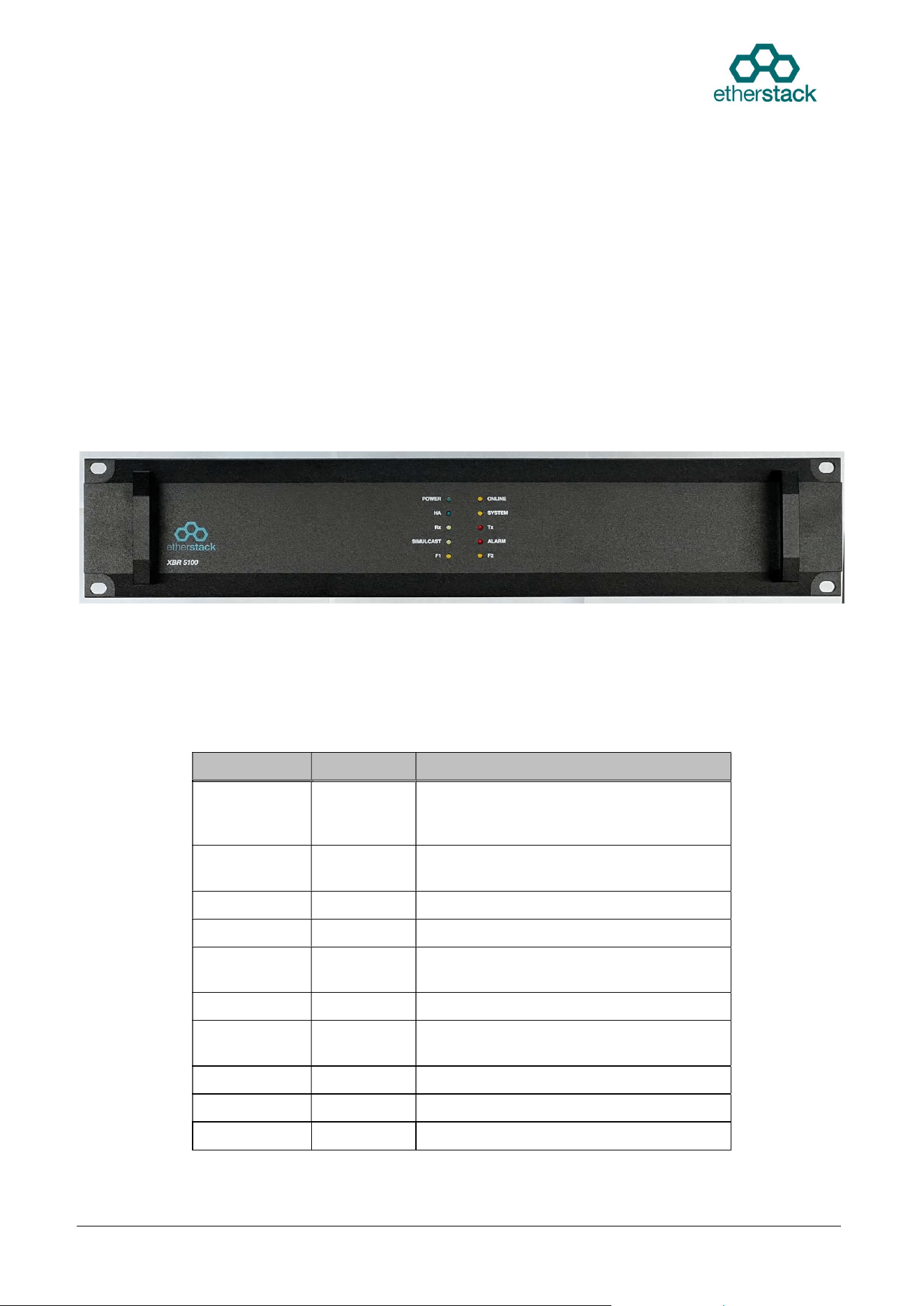
1.2.1 Front Panel
The XBR5100 front panel provides the user with the real time status of the XBR5100.
1.2.2 Front Panel LEDs
The table below explains the functions of the front panel LEDs. Each LED indicates the status of the
XBR5100 in real time.
LED COLOR STATUS
POWER GREEN
The power supply voltage is within limits.
No display indicates the supply voltage is
not present or outside specified limits.
ONLINE AMBER The device is ready for operation when
solid. Other specific state when blinking.
HA BLUE High Availability mode is active.
SYSTEM YELLOW System connection is active.
RX AQUA A wanted signal is being received by the
receiver.
TX RED The transmitter is transmitting RF power.
SIMULCAST GREEN The transmitter is operating in simulcast
mode (for simulcast ready variants only).
ALARM RED A preconfigured alarm condition exists.
F1 YELLOW Reserved
F2 YELLOW Reserved
Doc Ref: ES2202-UM01_v104 Etherstack Proprietary Information Page: 10 of 17
Date: 06 January 2026 © Etherstack Pty Ltd. 2026
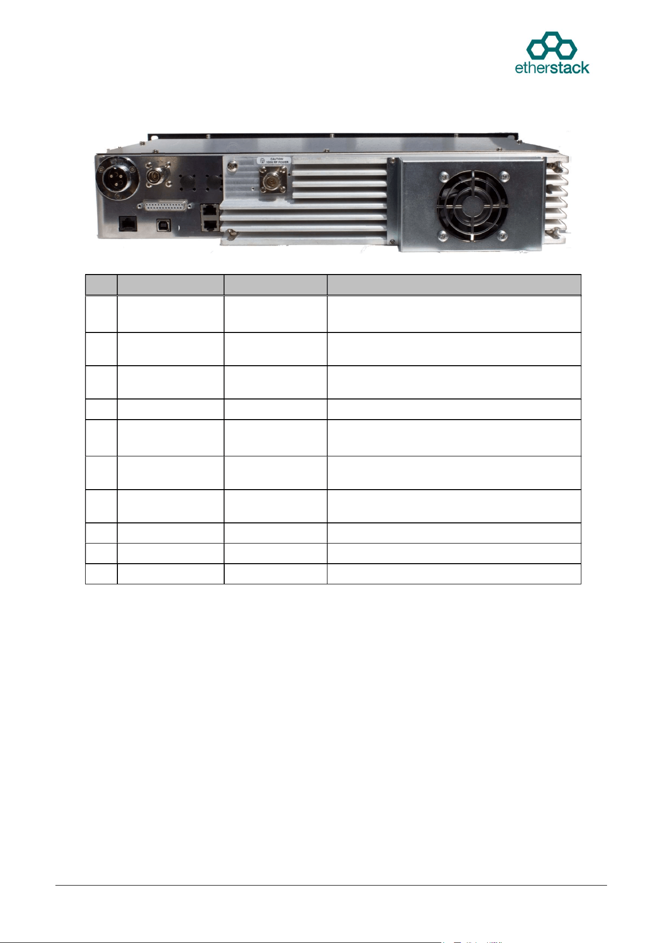
1.2.3 Rear Panel
The XBR5100 rear panel provides the user with all functional connections as well as the passive
heatsink and active cooling fan.
Connector Type Function Description
1 GX25 Style
Power Connector
DC Power input 13.8V DC power input.
28V DC power input (For T5 variants only)
2 N TYPE RX input The input to the receiver for full duplex
operation.
3 N TYPE TX output The RF power output from the transmitter for
full duplex operation.
4 BNC Timing reference 1 PPS input (for simulcast ready variants only).
5 BNC Frequency
reference
10 MHz frequency reference input
(for simulcast ready variants only).
6 RJ45
V.24 Interface Legacy interface for interoperability with
Motorola’s V.24 Interface.
7 RJ45 Ethernet First Ethernet Port (for network connection and
configuration)
8 DB25 External I/O General purpose I/O.
9 USB USB TYPE B Service Interface
10 RJ45 Ethernet Second Ethernet Port (for HA)
1.3 XBR5100 Internal Modules
The XBR5100 consists of a full duplex RF module contained within a shielded metal housing and a
Radio Controller board integrated on a single PCB, an XBR Controller Module and an Application
Module. The XBR Controller Module is a single PCB which implements layers 1 through 3 of the air
interface with its DSP and provides the interface to rear panel connectors. The Application Module is a
commercial off-the-shelf (COTS) computer module mounted on the XBR Controller Module
implementing advanced network functionality and a graphical user interface that controls the entire
device. Using advanced yet simplified circuit designs, the size and complexity is reduced. This affords
a number of advantages including;
Cost reduction
Improved reliability and MTBF by reducing number of components
Consistent and improved manufacturing process
Elimination of connectors and cabling
Reduction of human error
Faster maintenance or swap out
1
2
3
4
5
6
7
8
9
10
Passive
Heatsink
Cooling Fan

Doc Ref: ES2202-UM01_v104 Etherstack Proprietary Information Page: 11 of 17
Date: 06 January 2026 © Etherstack Pty Ltd. 2026
1.3.1 Exciter Module
The Exciter module generates the low level, on frequency, RF transmitter signal which is later amplified
to nominal output power level by the Power Amplifier module. The exciter consists of a Voltage
Controlled Oscillator (VCO) and associated main RF board, which, in conjunction with the reference
oscillator and the PLL circuitry, forms a two-point modulation programmable frequency synthesiser.
Frequency programming data is received from the Radio Controller.
1.3.2 Receiver Module
The receiver section accepts the low-level RF input signal and amplifies, filters and conditions the
signal prior to detecting the wanted audio component. The Receiver features the same advanced
synthesiser and wide bandwidth as the Exciter.
1.3.3 Radio Controller Module
The Radio Controller section is physically located towards the centre on the main board and controls all
signal connections (apart from the RF connections). It controls the operation of the RF sections and
acts as the interface between the user controls, indicators and the RF sub sections. Together with the
VF DSP chip, processed transmit and received audio is passed to and from the Exciter and Receiver
sections as well as providing all other audio signalling functions of the transceiver.
1.3.4 Power Amplifier Module
The PA receives the low-level modulated RF signal from the Exciter RF output and amplifies and filters
it to final output power level. Forward and reflected power voltages are fed to the Radio Controller.
1.3.5 XBR Controller Module
The XBR Controller Module hosts the Application Module and includes a DSP that implements the
analog FM and P25 air interface protocol stack. It also provides the connection to external
equipment accessible from the rear panel.
1.3.6 Application Module
The Application Module is a Commercial Off-The-Shelf (COTS) computer module with network
capabilities and supports high level networked features such as the eBSC and Web based graphical
user interface (Web UI).
Doc Ref: ES2202-UM01_v104 Etherstack Proprietary Information Page: 12 of 17
Date: 06 January 2026 © Etherstack Pty Ltd. 2026
2 Installation & Operation
2.1 Installation
The XBR5100 Radio is securely packaged for transport within a cardboard box. Before unpacking the
XBR5100 radio, please inspect the packaging for signs of damage and report any damage to your
XBR5100 distributor.
Upon unpacking the XBR5100 radio, please ensure that all items shipped were received and report any
missing items to your XBR5100 distributor.
Confirm the fan is free from obstructions, as operation of the radio will be affected if any packaging or
shipping damage causes the fan to stop working.
If you intend to install the radio in an equipment, rack consult the supplier’s instructions for your
system. If the radio is to be used in a stand-alone configuration, ensure that it is in a secure, dry
location with sufficient air space around it to allow for adequate ventilation. It is recommended that the
chassis is earthed to the equipment rack.
Please refer to the product specification sheet for band specific power requirements.
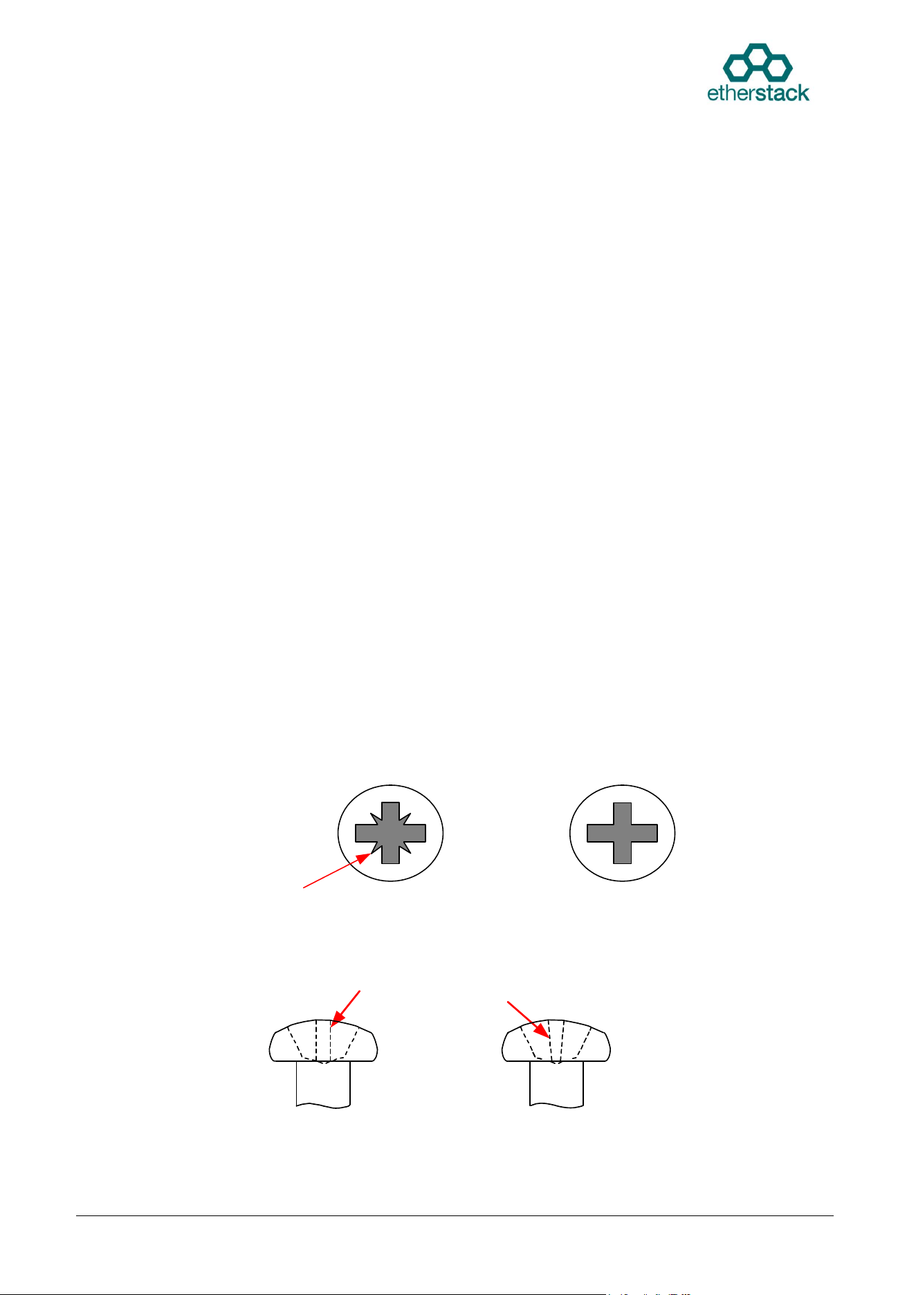
2.2 Screw Head Types
Modern screws employ a wide variety of drive designs, each requiring a different type of tool to drive
them. Etherstack has chosen the Pozidriv® screw head and screwdriver as the preferred screw type on
all its products, sizes 1 & 2. This is because the Pozidriv system is the choice for high volume
assembly operations. It provides self-centering system and excellent driving control with less operator
fatigue.
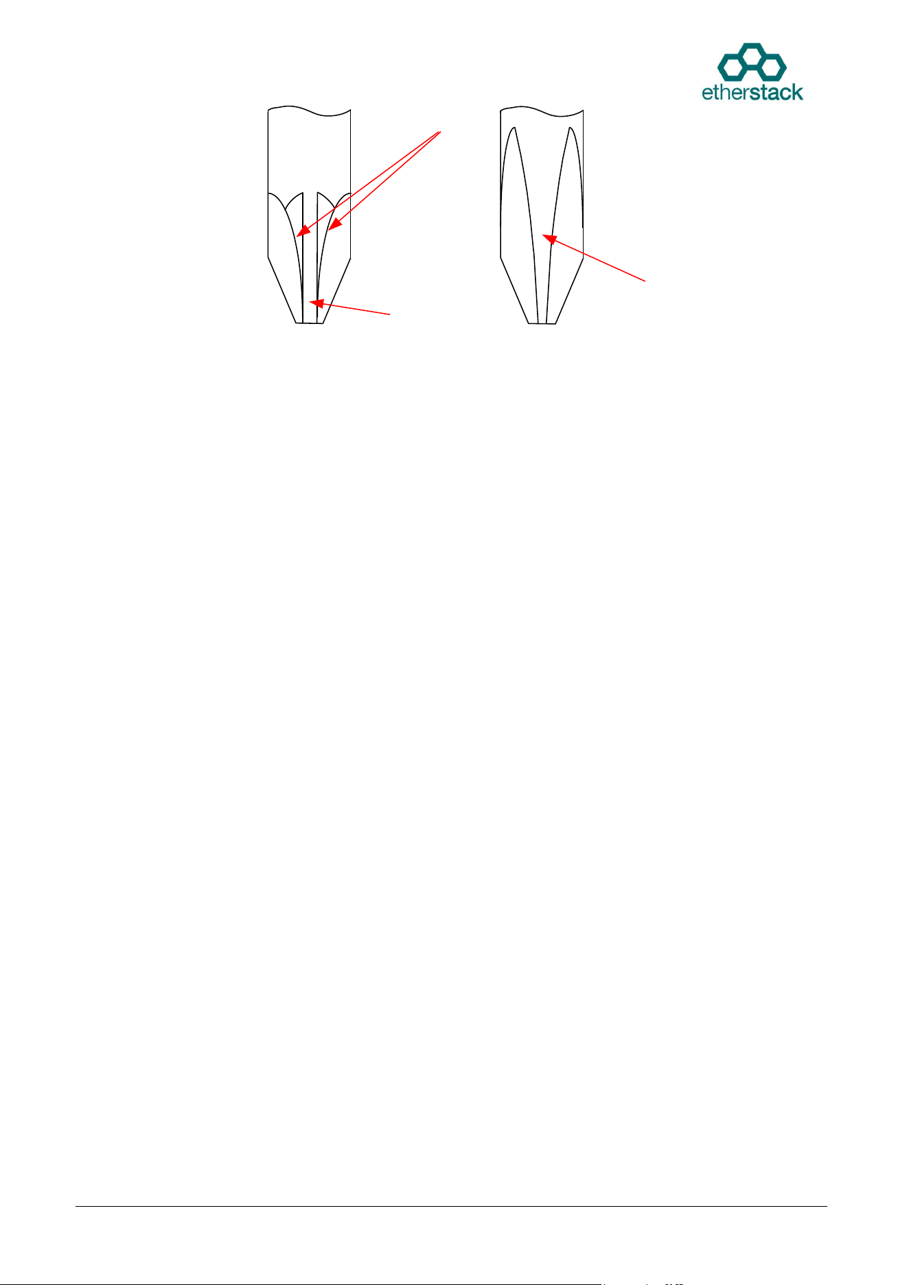
It is similar to the Phillips crosshead. The differences lie in the way that the heads are machined. The
Phillips head has 4 simple slots cut out of it, whereas in the case of the Pozidriv each slot is the result
of two machining processes at right angles. The result of this is that the arms of the cross are parallel
sided in the case of Pozidriv and tapered in the case of Phillips. The Pozidriv has four additional points
of contact and does not have the rounded corners that the Phillips screwdriver has.
Phillips screwdrivers will usually work in Pozidriv screws, but Phillips screwdrivers are likely to slip or
tear out the screw head when used in Pozidriv screws. It is important that you use the correct type and
size screwdriver to avoid damaging the screw head.
Extra contact points
Figure 1-1 Top view of screw heads
Pozidriv
Philliips
Parallel sides
Tapered sides
Figure 1-2 Side View of screw Heads
Doc Ref: ES2202-UM01_v104 Etherstack Proprietary Information Page: 13 of 17
Date: 06 January 2026 © Etherstack Pty Ltd. 2026
Extra contact ridges
Parrallel driving flute
Tapered driving flute
Figure 1-3 Screw driver Tip View
Not used in
this product
Pozidriv
Phillips
2.3 Operation
Setting up the XBR5100 to operate as required is straightforward and involves one main step:
Using a PC with a web browser, connect the PC in the same local network or directly and
access the Web GUI of the XBR5100. Set the appropriate parameters as required.
Note: All XBR5100s are set up with a standard default configuration that does not include any user
channels. A channel must be configured before the device may be operated.
2.3.1 Setting to Work
The XBR5100 can operate in several different modes. One typical use, is as an element of a networked
system.
Please refer to the Etherstack website for more details.
2.3.2 Adjustments
The XBR5100 features a number of adjustable parameters including TX power, TX VCO deviation, TX
reference oscillator deviation and TX reference oscillator frequency. All of these are adjusted with the
Web GUI. The XBR5100 comes pre-aligned from the factory, so in most cases no alignment will be
necessary.

Doc Ref: ES2202-UM01_v104 Etherstack Proprietary Information Page: 14 of 17
Date: 06 January 2026 © Etherstack Pty Ltd. 2026
3 Alignment & Testing
Please refer to the Etherstack website for further details.
Doc Ref: ES2202-UM01_v104 Etherstack Proprietary Information Page: 15 of 17
Date: 06 January 2026 © Etherstack Pty Ltd. 2026
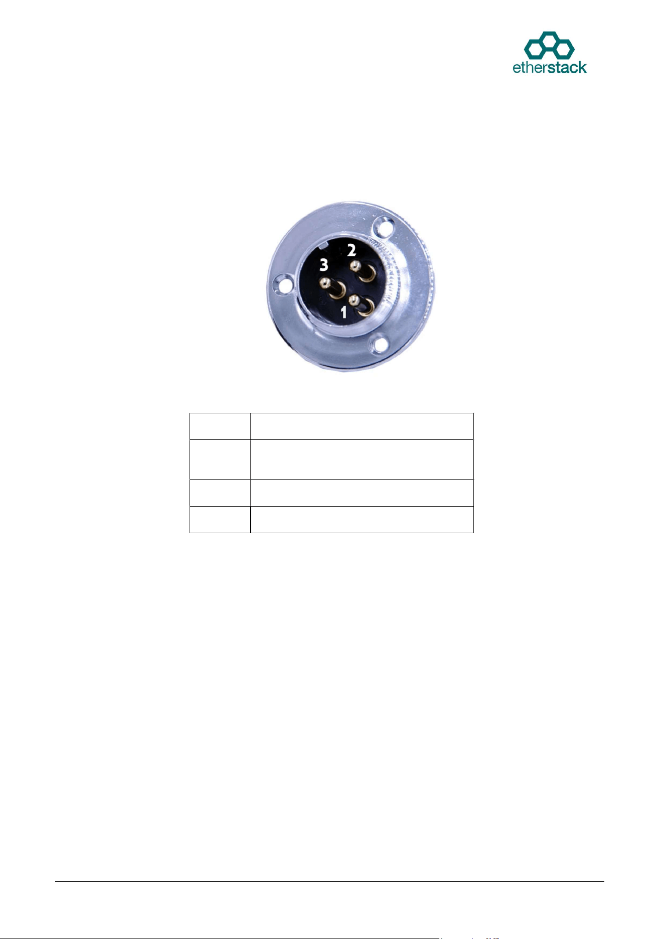
4 Power
The XBR5100 is powered via a 13.8V DC input on its rear panel.
4.1 DC Input Pinouts
Figure 4.1 DC INPUT Supply (GX25 Style)
PINS Description
1 + 28V DC
(for T5 variants only)
2 GND
3 + 13.8 V DC
Doc Ref: ES2202-UM01_v104 Etherstack Proprietary Information Page: 16 of 17
Date: 06 January 2026 © Etherstack Pty Ltd. 2026
5 Specifications
The XBR5100 series is designed to conform with the requirements of the following standards*:
AS/NZS 4295
FCC Part 90
TIA/EIA-603
IC (ISED)
TIA/EIA-102 (P25 CAP)
* Conforms but not necessarily approved. Please consult Etherstack regarding current type approvals
and for the latest and current XBR5100 Specification Data sheet.
5.1 Operating Frequency Bands
The XBR5100 is available in a number of models which cover a specific range of operating frequency
bands. Refer to Section 5.6 for details of the band breakdown.
5.2 General
Table 5-1 General Specifications
Parameter Specification
XBR5100 Rack Size: 2RU Case
XBR5100 Overall Physical Size 89mm high, 325mm deep, 483mm wide
* Requires extra depth (40mm) for Fan
operation.
Weight 8 kg
Supply Voltage: 13.8V DC ± 20%
Operating Temperature: -30 to +60ºC.
Standard LED indicators:
POWER, ONLINE, HA, SYSTEM, RX, TX,
SIMULCAST and ALARM.
See 1.2.2
Frequency Range: VHF 136-174 MHz (D5)
UHF 400-470 MHz (N5), 450-520 MHz (P5),
792-825 MHz (T5).
Synthesis Method:
Non mixing PLL
Fractional N synthesiser.
Modulation: C4FM, Analog wideband / narrowband
Channel Spacing: 12.5 kHz, 25kHz software selectable.
Synthesiser Step Size: 5 kHz or 6.25 kHz.
Channels: 127 Software configurable and selectable.
Doc Ref: ES2202-UM01_v104 Etherstack Proprietary Information Page: 17 of 17
Date: 06 January 2026 © Etherstack Pty Ltd. 2026
5.3 Transmit
See product specification sheet.
5.4 Receive
See product specification sheet.
5.5 Ancillaries
See product specification sheet.
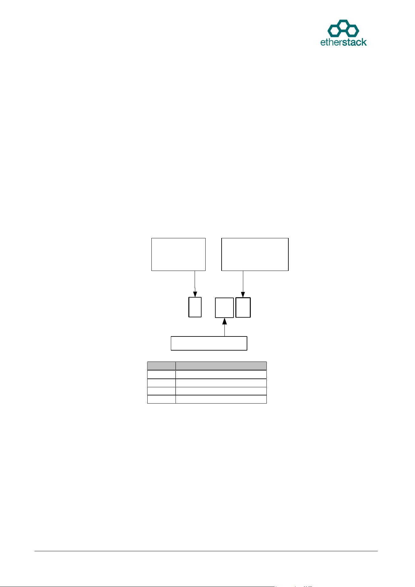
5.6 XBR5100 Model Number Configuration Guide
The XBR5100 build can be specified by the model number. The diagram below shows how the model
number is derived from the wanted options. The “I” suffix represents that the XBR Control Module is
integrated into the repeater in those models. Consult Etherstack for availability details on specific
configurations and options.
Table 5-2 XBR5100 frequency bands
Please refer to Etherstack website for the latest revision of the specifications.
Band Frequency
D5 VHF (136-174 MHz)
N5 UHF-Low (400-470 MHz)
P5 UHF-High (450-520 MHz)
T5 UHF 700 / 800 MHz
XBR5100 I
Max Tx Power
H 50 Watts
V 100 Watts
Frequency Band
Simulcast
1 Ready
0 Not Ready