PDF export of the original HTML instructions
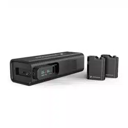
Spectera
Bidirectional, wireless broadband ecosystem
Spectera v1.4 | 09/2025

Contents
1. Preface............................................................................................................................................ 5
2. Quick start..................................................................................................................................... 6
3. Product information......................................................................................................................8
Spectera System........................................................................................................................8
Base Station............................................................................................................................... 9
SEK..............................................................................................................................................11
DAD.............................................................................................................................................12
Accessories............................................................................................................................... 13
Accessories for the Base Station...................................................................................13
Accessories for the SEK..................................................................................................15
Accessories for the DAD................................................................................................. 16
CHG 70N-C network-enabled charger...........................................................................17
BA 70 rechargeable battery and L 70 USB charger.....................................................19
Modular L 6000 charger................................................................................................. 20
Charging modules for L 6000 charger..........................................................................22
4. User manual ............................................................................................................................... 25
Base Station............................................................................................................................. 26
Get started........................................................................................................................ 26
General information for the System..............................................................................29
Product overview............................................................................................................. 30
Installing slot-in cards.....................................................................................................32
Connecting/disconnecting the Base Station to/from the power supply
system................................................................................................................................35
Connecting to a network................................................................................................ 36
Connecting antennas.......................................................................................................39
Connecting word clock.................................................................................................... 41
Connecting audio via Dante®......................................................................................... 44
Connecting audio via MADI............................................................................................46
Changing the fan filter.................................................................................................... 47
Installing the Base Station in a rack............................................................................. 49
Switching the Base Station on and into standby......................................................... 51
Activating a license (general).........................................................................................52
Using the headphone output..........................................................................................54
Meaning of the LED.........................................................................................................55
Information on the display..............................................................................................56

Navigating the menu....................................................................................................... 57
Menu structure.................................................................................................................58
Updating the Base Station............................................................................................. 69
SEK.............................................................................................................................................70
Product overview..............................................................................................................70
Inserting and removing the rechargeable battery....................................................... 72
Mounting the antenna..................................................................................................... 75
Using the protection cap................................................................................................ 76
Connecting a microphone / instrument........................................................................ 77
Connecting earphones.....................................................................................................79
Changing the belt clip..................................................................................................... 81
Meaning of the LEDs.......................................................................................................84
Switching the SEK on and off........................................................................................ 87
Information on the display..............................................................................................88
Pairing the SEK to the Base Station.............................................................................. 91
Updating the SEK.............................................................................................................92
DAD............................................................................................................................................93
Product overview............................................................................................................. 93
Information on antenna setup........................................................................................94
Meaning of the LED.........................................................................................................96
Placing on a stand........................................................................................................... 97
Connecting/disconnecting the antenna....................................................................... 99
Antenna cable extension............................................................................................... 102
Updating the DAD.......................................................................................................... 103
CHG 70N-C charger.............................................................................................................. 104
Product overview............................................................................................................104
Connecting/disconnecting the charger to/from the power supply system........... 106
Connecting a charger in a network............................................................................. 108
Cascading chargers....................................................................................................... 109
Charging the rechargeable battery............................................................................... 111
Power saving mode.........................................................................................................113
L 70 USB charger................................................................................................................... 114
Connecting/disconnecting the charger to/from the power supply system............114
Charging the rechargeable battery.............................................................................. 115
Modular L 6000 charger........................................................................................................116
Product overview.............................................................................................................116
Connecting/disconnecting the L 6000 to/from the power supply system............. 117

Connecting the L 6000 to a network........................................................................... 118
Installing a charging module in the L 6000 charger................................................. 120
Installing the L 6000 in a rack......................................................................................122
Switching the L 6000 on and off................................................................................. 124
Charging the rechargeable batteries in the L 6000 charger.................................... 125
Meaning of the LEDs......................................................................................................127
Preparing rechargeable batteries for storage (storage mode)................................. 129
Resetting settings (factory reset)................................................................................ 130
Updating the firmware................................................................................................... 131
Operating the L 6000 via a network............................................................................132
Cleaning and maintenance................................................................................................... 133
5. Knowledge base........................................................................................................................ 134
Network guide........................................................................................................................ 134
General requirements.................................................................................................... 134
Network setups............................................................................................................... 137
Ports, protocols and services........................................................................................141
Best practice................................................................................................................... 145
Security guide.........................................................................................................................147
Key product security features.......................................................................................147
How to use the security features.................................................................................152
Troubleshooting......................................................................................................................159
License activation fails.................................................................................................. 159
No device access via the WebUI.................................................................................. 161
The Base Station cannot be found.............................................................................. 162
6. Specifications............................................................................................................................ 163
Spectera System.................................................................................................................... 163
Base Station............................................................................................................................165
SEK........................................................................................................................................... 168
DAD.......................................................................................................................................... 170
CHG 70N-C charger............................................................................................................... 172
BA 70 rechargeable battery..................................................................................................174
L 70 USB charger................................................................................................................... 175
Modular L 6000 charger....................................................................................................... 176
LM 6060 | LM 6061 | LM 6062 | LM 6070 charging modules........................................... 178

Spectera
1. Preface
PDF export of the original HTML instructions
This PDF document is an automated export of an interactive set of HTML instructions.
It may be the case that not all contents and interactive elements are contained in the
PDF as they cannot be presented in this format. Furthermore, automatically generated
page breaks may cause coherent contents to be moved slightly. We can therefore only
guarantee the completeness of the information in the HTML instructions, and recommend
that you use these. You can find these in the download section of the website under
www.sennheiser.com/download.
5
Spectera
2. Quick start
All necessary information for activating the license and configuring the required ports of
the device.
When starting up the Base Station for the first time, it is necessary to have a direct internet
connection to activate the license. Additionally, certain ports must be enabled (especially for
the organization/enterprise firewall) for communication between software and devices.
1. Connect the Base Station to a network:
Plug one side of the network cable into the Control socket.
Plug the other side of the network cable to a switch or router.
The Base Station has been connected to a network.
2. Enable necessary ports for activation:
Please contact your IT administrator to provide Internet access to the License Server
and any NTP server by opening the required network ports and to provide DNS
settings via DHCP to the device.
Address Port Protocol Type Service Usage
my.nalpeiron.com 80 HTTPS
(TCP)
Unicast Sennheiser
License Server
Activation of
devices
6
| 2 - Quick start
ANY (see list of NTP
servers)
123 NTP Unicast NTP Time
Server
Synchronize
system time
You can find the complete overview of all ports at Ports, protocols and
services.
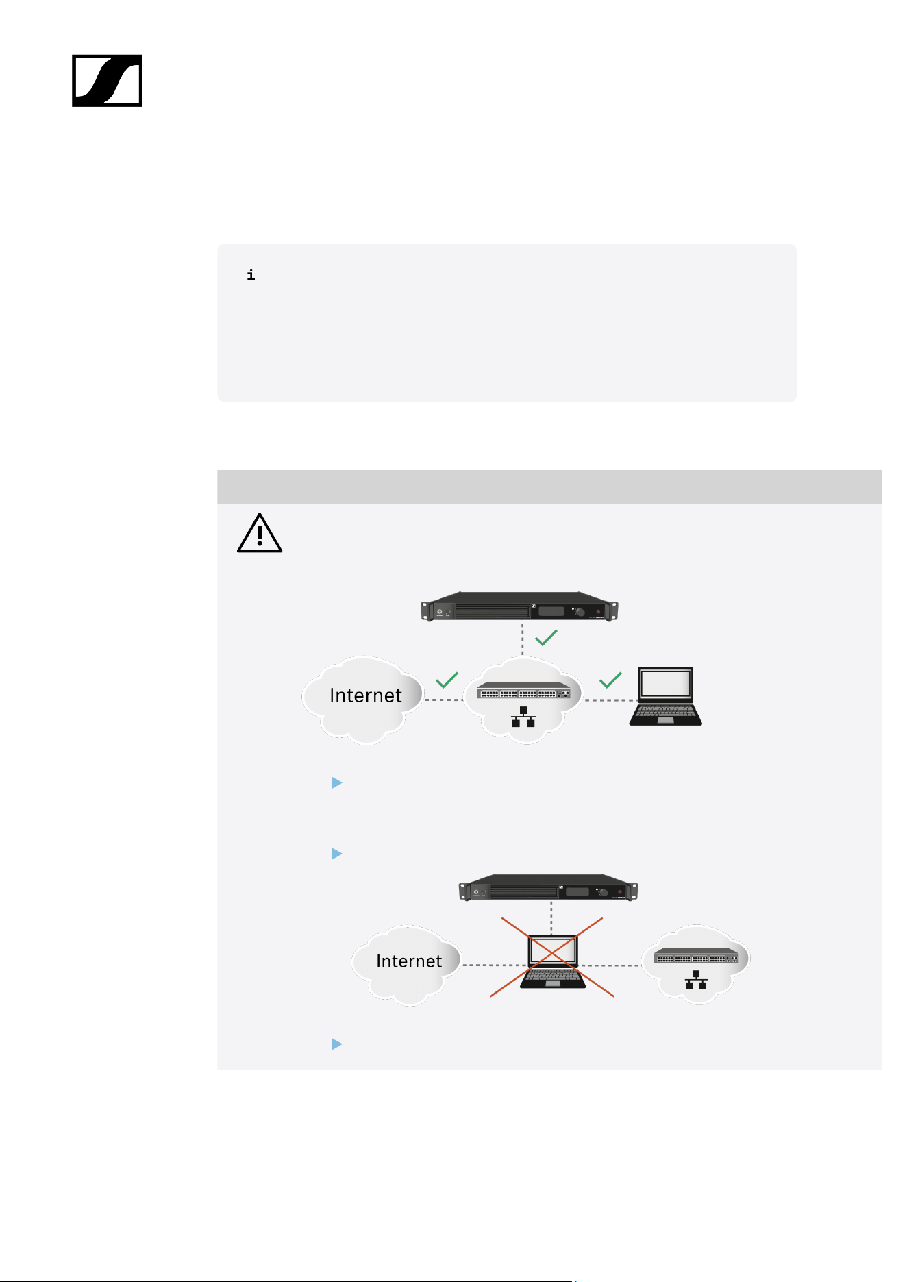
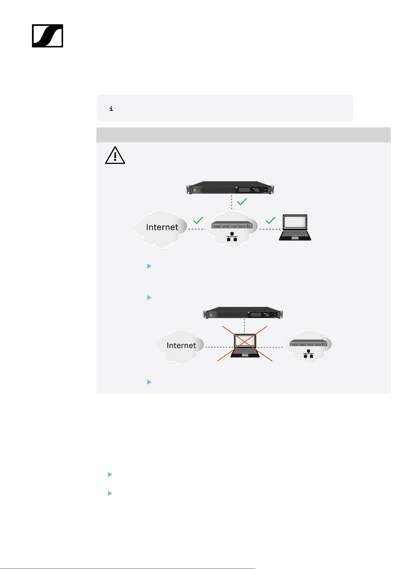
3. Ensure that the network has an Internet connection and activate the license:
NOTICE
License activation requires a direct Internet connection to the device
In order to activate the Base Station using the 18-digit license code, a direct Internet
connection is required.
Please connect your Base Station directly to a network with Internet access via
a switch or router. For more information, refer to the chapter Connecting to a
network.
Direct connections via laptop etc. are not supported for activation!
The Internet is only required once for activation.
If you want to activate a license via LinkDesk, follow the steps described here:
Activating a license (LinkDesk).
If you want to activate a license via Spectera WebUI, follow the steps described here:
Activating a license (webUI).
7

Spectera
3. Product information
All information about the product, the scope of delivery and the available accessories.
Spectera System
Sensing Capabilities - Audio detection and transmission
Spectera devices (Base Station, DAD, SEK) build audio transmission system for professional
use. Once paired, SEK mobile devices can transmit audio signals captured by a connected
microphone over radio frequencies. Due to its bi-directionality, the SEK is able to receive
audio signals from DAD and the sound comes out of the headphones, if any connected. Here
how it works:
Transmission:
The SEK picks up sound from microphone and turns it into electrical signals.
These signals are then prepared for transmission by boosting and modifying them.
The signals are sent over radio waves to the DAD Antenna.
The DAD antenna changes the radio back into electrical signals and sent them to the
Base Station for further audio processing.
Receiving:
The Base Station forward audio signals to the DAD Antenna.
These signals are then prepared for transmission by boosting and modifying them.
The signals are sent over radio waves to the SEK mobile devices.
The SEK changes the radio back into electrical signals and at a further stage, sound
will be directed to connected headphones.
8
| 3 - Product information
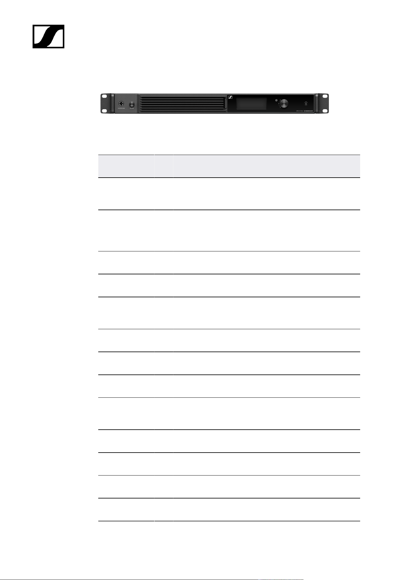
Base Station
Base Station | 1350 - 1525 MHz | Art. no. 509162
The license for the Base Station is available in the following versions:
Name Art.
no.
Frequency range Certified Countries*
SPECTERA LIC
(ZONE 01)
700
532
UHF (470 - 608 MHz, 630 - 698 MHz)
1G4 (1350 - 1400 MHz)
EU + EFTA, United
Kingdom, Turkey
SPECTERA LIC
(ZONE 02)
700
533
UHF (470 - 608 MHz, 657 - 663 MHz)
1G4 (1435 - 1525 MHz Certification
pending)
USA
SPECTERA LIC
(ZONE 03)
700
534
UHF (470 - 608 MHz, 657 - 663 MHz) Canada
SPECTERA LIC
(ZONE 04)
700
535
UHF (470 - 534 MHz, 534 - 608 MHz,
630 - 698 MHz)
Singapore
SPECTERA LIC
(ZONE 05)
700
536
UHF (470 - 608 MHz, 630 - 698 MHz)
1G4 (1350 - 1400 MHz)
South Africa -
Certification pending
SPECTERA LIC
(ZONE 06)
700
537
UHF (470 - 608 MHz, 630 - 694 MHz) Malaysia, Qatar
SPECTERA LIC
(ZONE 07)
700
538
UHF (470 - 510 MHz) Israel - Certification
pending
SPECTERA LIC
(ZONE 08)
700
539
UHF (487 - 608 MHz, 630 - 694 MHz) Indonesia
SPECTERA LIC
(ZONE 09)
700
540
UHF (470 - 608 MHz, 630 - 694 MHz)
1G4 (1350 - 1400 MHz)
United Arab Emirates
SPECTERA LIC
(ZONE 10)
700
541
UHF (470 - 608 MHz, 630 - 698 MHz) Philippines
SPECTERA LIC
(ZONE 11)
700
542
UHF (520 - 608 MHz, 630 - 694 MHz) Australia
SPECTERA LIC
(ZONE 12)
700
543
UHF (510 - 606 MHz) New Zealand
SPECTERA LIC
(ZONE 13)
700
544
UHF (479 - 565 MHz) Hong Kong
9
| 3 - Product information
Name Art.
no.
Frequency range Certified Countries*
SPECTERA LIC
(ZONE 14)
700
728
UHF (470-0608 MHz) Egypt, Mexico
* It is the responsibility of the user to inform themselves about the current local regulatory
and certification requirements and to comply with them using wireless systems.
You can find more detailed information about the Base Station in the following
sections:
• Startup and operation: Base Station
• Specifications: Base Station
10
| 3 - Product information
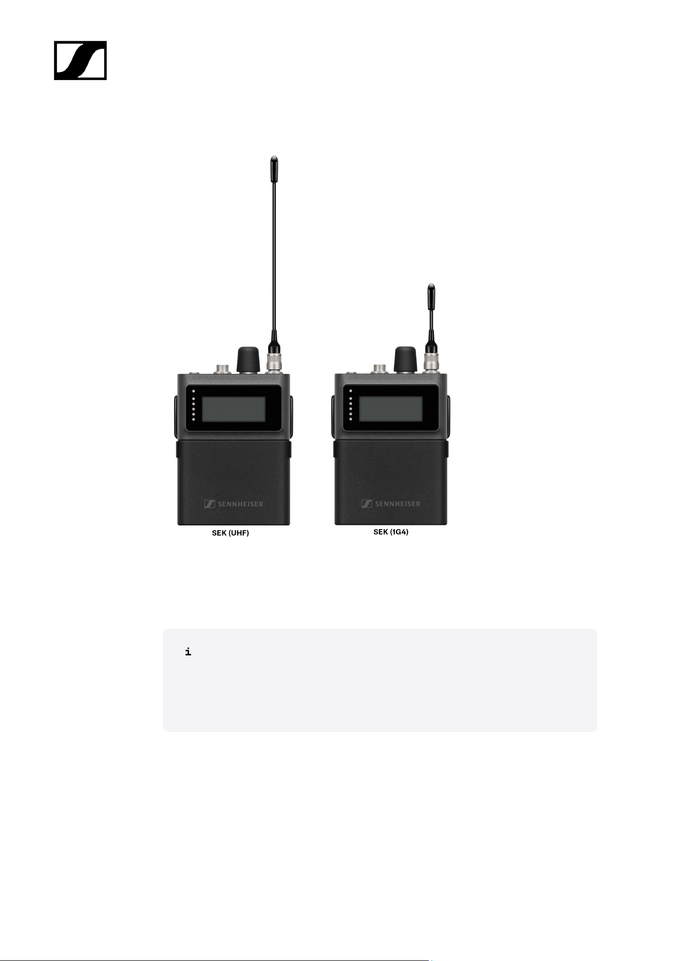
DAD
The Digital Antenna Directional (DAD) is available in the following versions:
DAD UHF | 470 - 698 MHz | Art. no. 509169
DAD 1G4 | 1350 - 1525 MHz | Art. no. 509170
You can find more detailed information about the DAD in the following sections:
• Startup and operation: DAD
• Specifications: DAD
12
| 3 - Product information
Accessories for the SEK
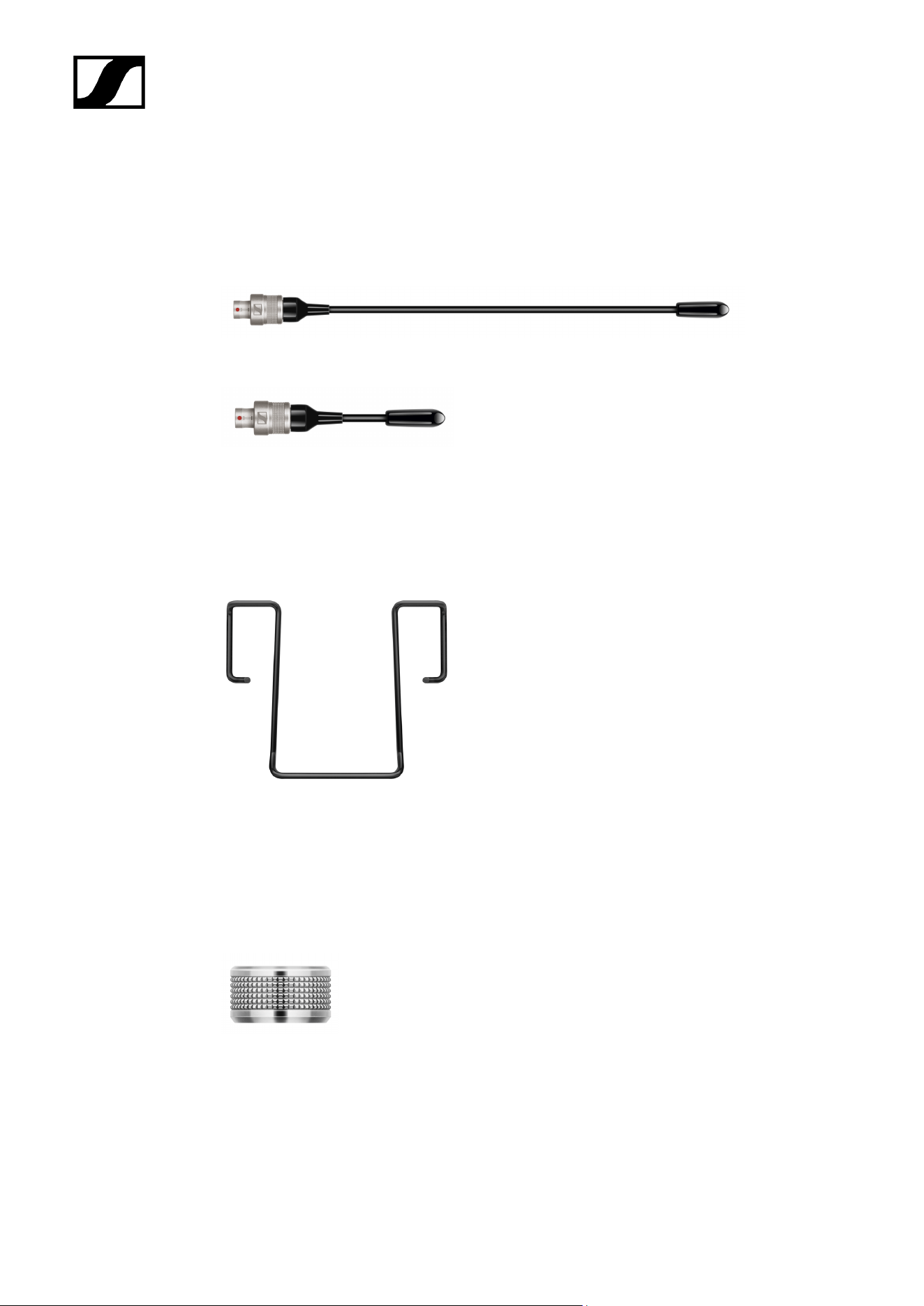
Spectera SEK Antenna
SEK Antenna (UHF) | 470 - 698 MHz | Art. no. 700066
SEK Antenna (1G4) | 1350 - 1525 MHz | Art. no. 700067
• See Mounting the antenna
Spectera SEK Belt Clip
SEK Belt Clip | Art. no. 700071
• See Changing the belt clip
3-pin protective cap MIC/LINE
Exchangeable protective cap for the microphone / instrument 3-pin connector | Art. no.
700072
• See Using the protection cap
15
| 3 - Product information
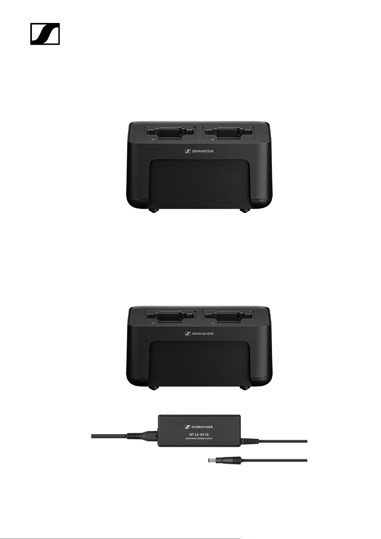
CHG 70N-C network-enabled charger
CHG 70N-C | Charger | Art. no. 700332
17

| 3 - Product information
CHG 70N-C + PSU KIT | CHG 70N-C charger with NT 12-35 CS power supply unit | Art. no.
700333
You can find more detailed information about the CHG 70N-C in the following
sections:
• Startup and operation: CHG 70N-C charger
• Specifications: CHG 70N-C charger | BA 70 rechargeable battery
18

| 3 - Product information
BA 70 rechargeable battery and L 70 USB charger
BA 70 | Rechargeable battery | Art. no. 508860
L 70 USB | Charger | Art. no. 508861
EW-D CHARGING SET | L 70 USB charger with two BA 70 rechargeable batteries | Art. no.
508862
You can find more detailed information about the BA 70 rechargeable battery and
the L 70 USB charger in the following sections:
• Startup and operation: L 70 USB charger
• Specifications: L 70 USB charger | BA 70 rechargeable battery
19
| 3 - Product information
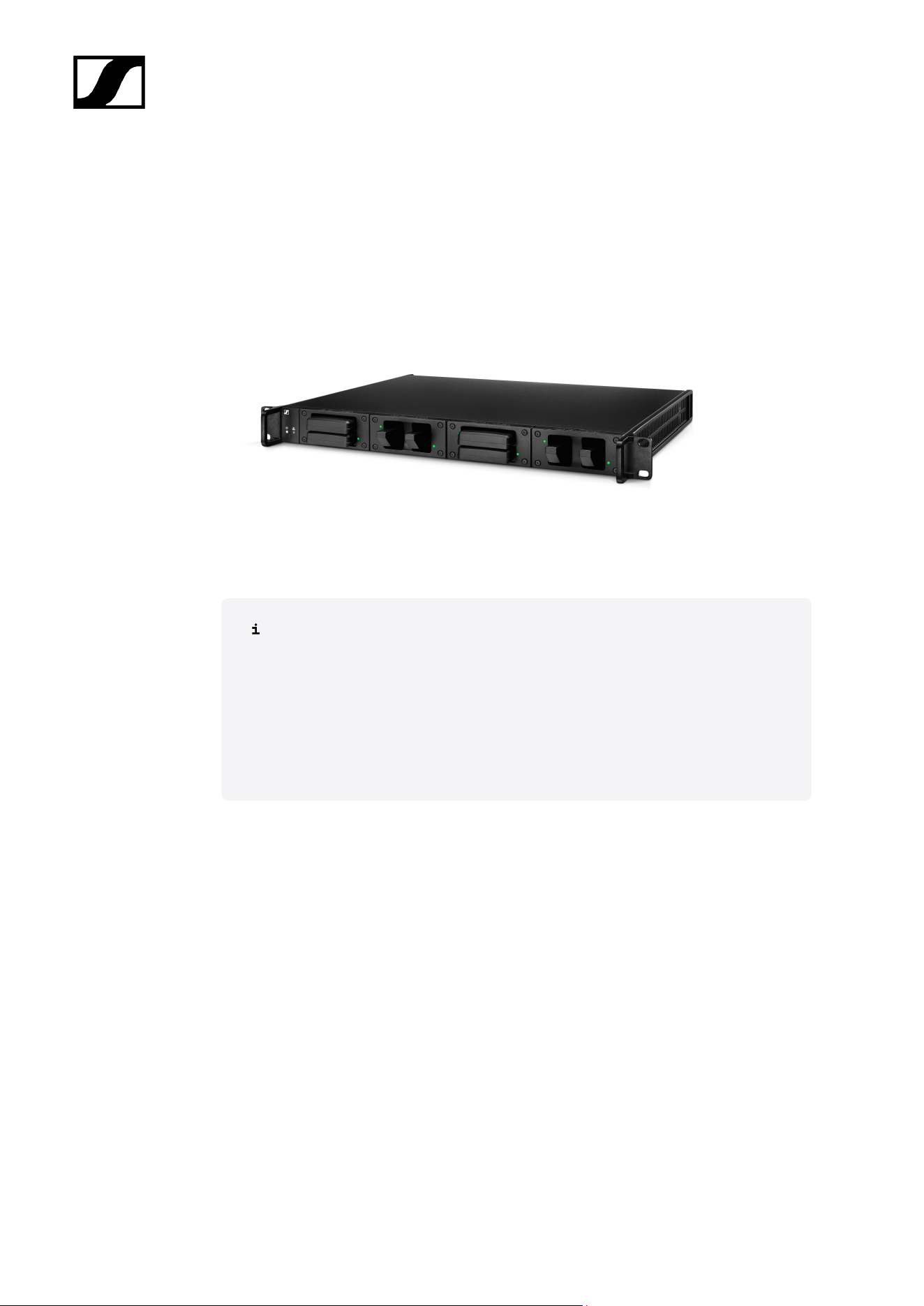
Modular L 6000 charger
The L 6000 charger is used to charge the BA 60, BA 61, BA 62 and BA 70 rechargeable
batteries.
The charging modules LM 6060 (for the BA 60), LM 6061 (for the BA 61), LM 6062 (for the BA
62) or LM 6070 (for the BA 70) are required to do so. The rechargeable batteries and charging
modules are available separately.
• L 6000 EU | Article no. 507300
You can find more detailed information about the L 6000 charger and the LM
6060, LM 6061, LM 6062 and LM 6070 charging modules in the following
sections:
• Installation and Operation: Modular L 6000 charger
• Specifications: Modular L 6000 charger and LM 6060 | LM 6061 | LM
6062 | LM 6070 charging modules
Delivery includes
• 1 L 6000 charger
• 1 mains cables (EU, UK, or US variant)
• 4 dummy caps including screws (preassembled)
• 4 rubber feet
• 1 quick guide
• 1 manual with safety instructions
• 1 manual with technical data and manufacturer declarations
Product overview
View with the charging modules and rechargeable batteries inserted:
20
| 3 - Product information
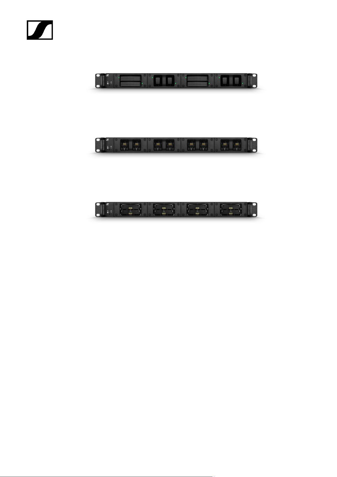
View with the LM 6060 charging modules without rechargeable batteries inserted:
View with the LM 6061 charging modules without rechargeable batteries inserted:
21
| 3 - Product information
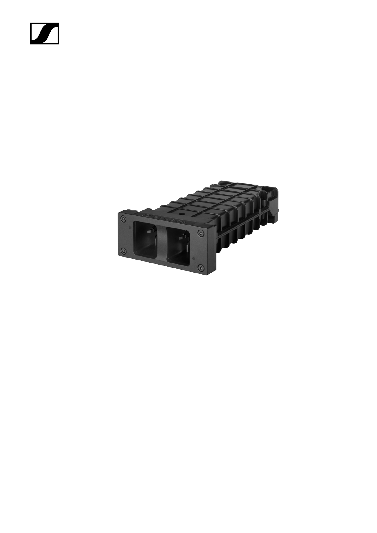
Charging modules for L 6000 charger
The following charging modules are available for the L 6000 charger:
LM 6060
The LM 6060 charging module is installed in the L 6000 charger to charge the BA 60
rechargeable battery.
LM 6060 | Article no. 507198
LM 6061
The LM 6061 charging module is installed in the L 6000 charger to charge the BA 61
rechargeable battery.
LM 6061 | Article no. 507199
22
| 3 - Product information
LM 6062
The LM 6062 charging module is installed in the L 6000 charger to charge the BA 62
rechargeable battery.
LM 6062 | Article no. 508516
LM 6070
The LM 6070 charging module is installed in the L 6000 charger to charge the BA 70
rechargeable battery of the Evolution Wireless Digital series.
23
| 3 - Product information
LM 6070 | Article no. 509457
24
Spectera
4. User manual
Detailed description of the start-up and operation of your selected hardware.
Instruction manuals about controlling the Spectera System via LinkDesk and
Spectera WebUI can be found here:
• Instruction manual LinkDesk
• Instruction manual WebUI
Important Information on License Activation
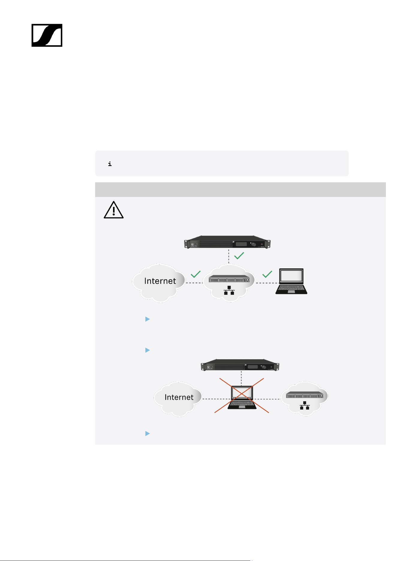
NOTICE
License activation requires a direct Internet connection to the device
In order to activate the Base Station using the 18-digit license code, a direct Internet
connection is required.
Please connect your Base Station directly to a network with Internet access via
a switch or router. For more information, refer to the chapter Connecting to a
network.
Direct connections via laptop etc. are not supported for activation!
The Internet is only required once for activation.
25
| 4 - User manual
Base Station
Get started
Get your Base Station ready to use in a few steps.
After unpacking the Base Station you must update the firmware before activating a licence.
If you use LinkDesk the update is mandatory before activating a licence.
NOTICE
License activation requires a direct Internet connection to the device
In order to activate the Base Station using the 18-digit license code, a direct Internet
connection is required.
Please connect your Base Station directly to a network with Internet access via
a switch or router. For more information, refer to the chapter Connecting to a
network.
Direct connections via laptop etc. are not supported for activation!
The Internet is only required once for activation.
26
| 4 - User manual
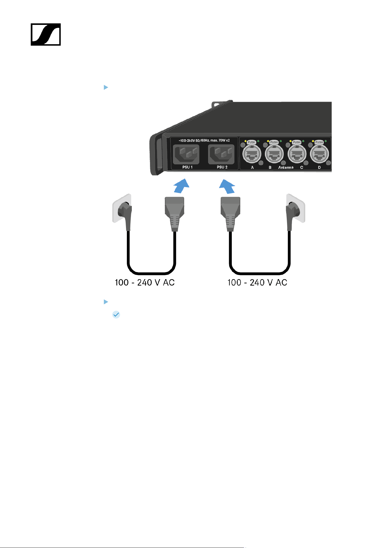
To connect the Base Station to the power supply system:
Connect one mains cable to the power socket on the rear side of the Base Station.
Connect one mains cable plug into a suitable wall socket.
The Base Station is connected to the power supply.
27
| 4 - User manual
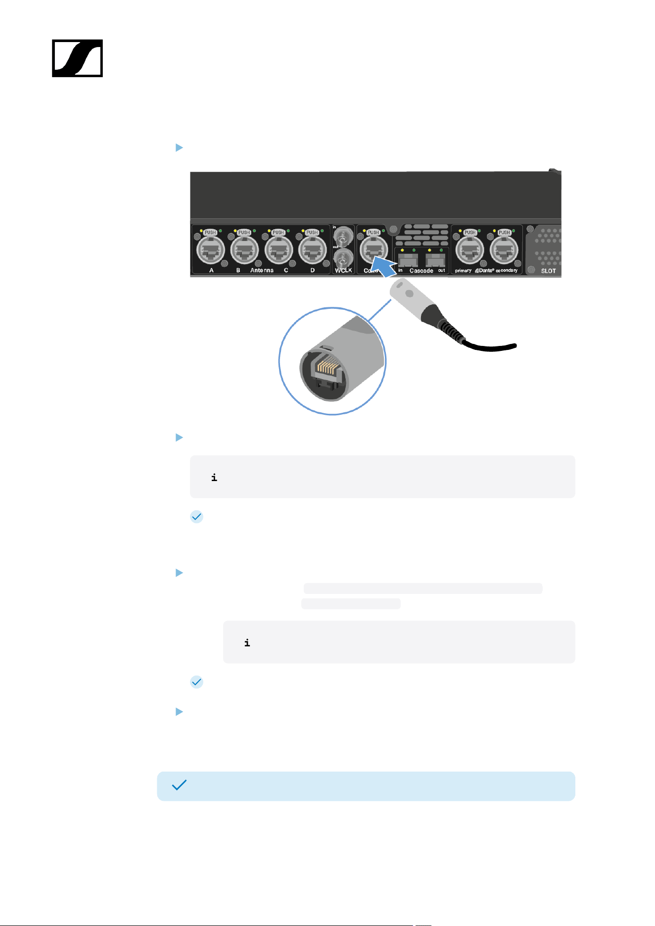
To connect the Base Station to a network:
Plug one side of the network cable into the Control socket.
Plug the other side of the network cable to a switch, router or directly to a computer.
The Base Station needs a direct Internet access!
The Base Station has been connected to a network.
To update the firmware:
If you want to use Spectera WebUI, it depends on the initial firmware version:
• Firmware ≤ 0.8.x: https://deviceIP/specteracontrol/index.html .
• Firmware ≥ 1.x.x: https://deviceIP/ .
The device IP can be found here: Network.
In some cases the internet browser might have trouble showing the page. Please
use the LinkDesk software.
If you want to use the free LinkDesk software: Download it from the Sennheiser
website sennheiser.com/linkdesk.
The update is mandatory before activating a licence.
Your Base Station is up to date.
You can now add a licence, see Activating a license (general).
28
| 4 - User manual
General information for the System
Here you can find general information for your use of the System.
A license has to be activated, otherwise you cannot use the Base Station.
The Base Station has two independend RF channels. Both variants of the antenna (UHF and
1G4) can be connected to the Base Station at the same time.
You can pair up to 128 mobile devices to a Base Station within one RF channel.
Mobile devices can only be paired and operated with one Base Station at a time.
29
| 4 - User manual
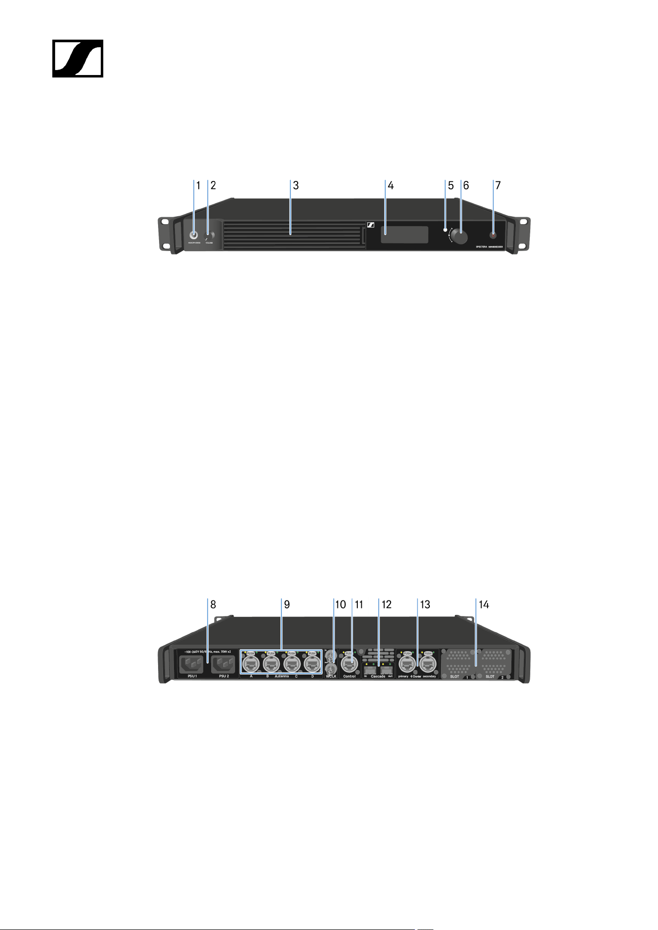
Product overview
Front
1 HEADPHONES socket
see Using the headphone output
2 VOLUME control for headphone
see Using the headphone output
3 Fan inlet with filter
see Changing the fan filter
4 Display for status information and operating menu
see Information on the display
5 LED to indicate the status
see Meaning of the LED
6 Jog-Dial (UP/DOWN/SET) for navigating the menu
see Navigating the menu
7 ON/OFF button
see Switching the Base Station on and into standby
Back
8 Power socket
see Connecting/disconnecting the Base Station to/from the power supply
system
9 4x ruggedized RJ45 Antenna ports
see Connecting antennas
10 Word clock in/out
see Connecting word clock
30

| 4 - User manual
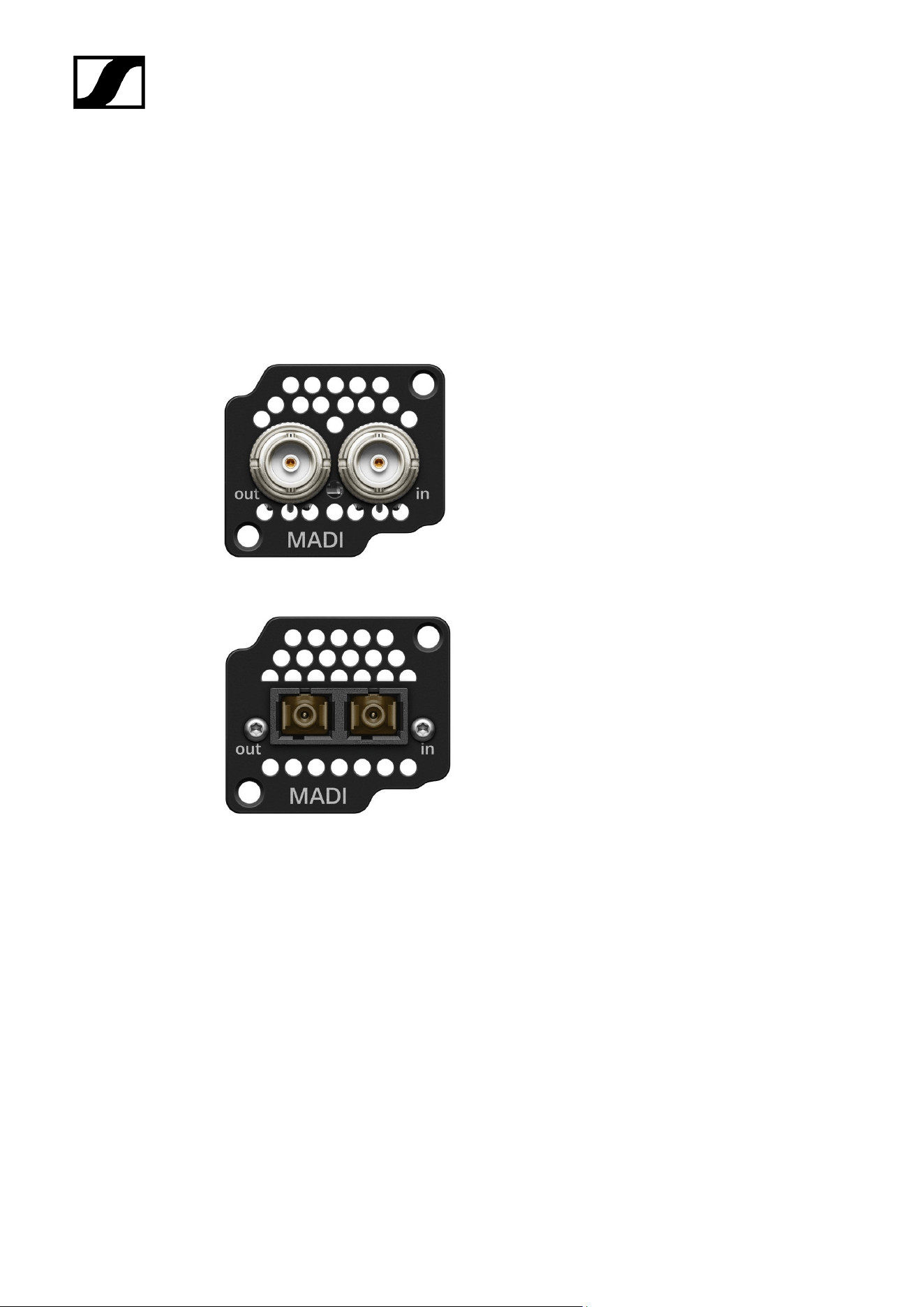
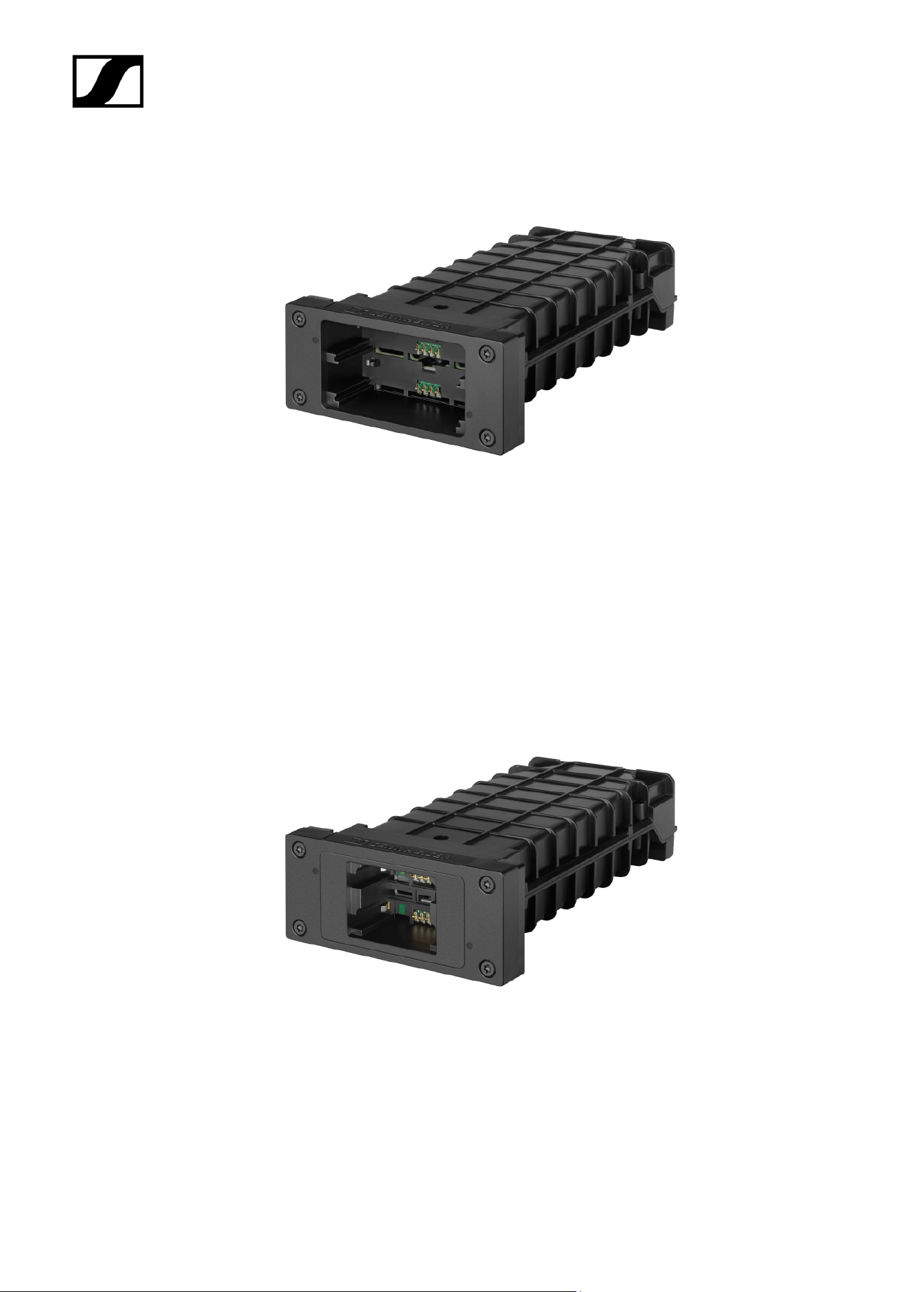
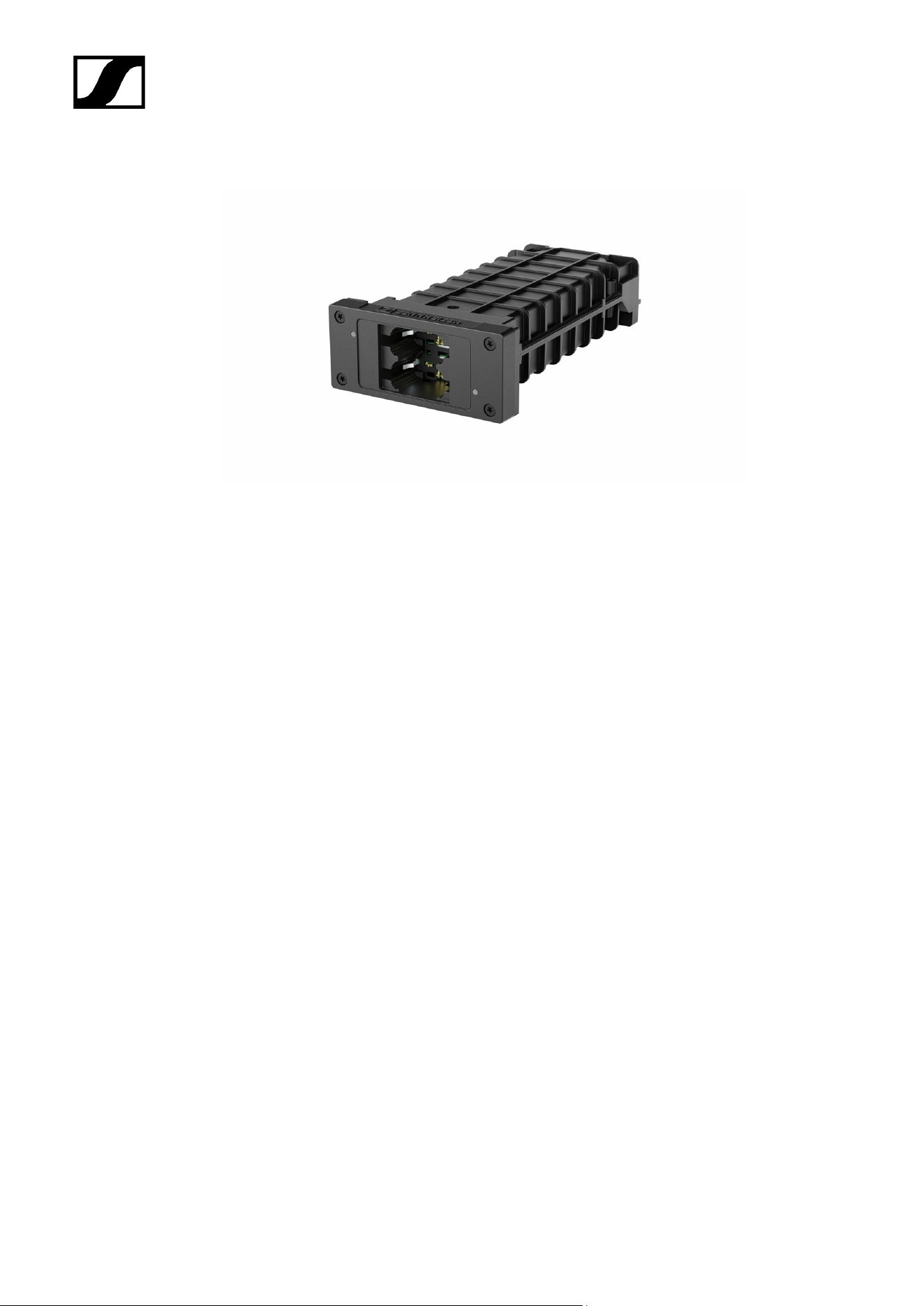
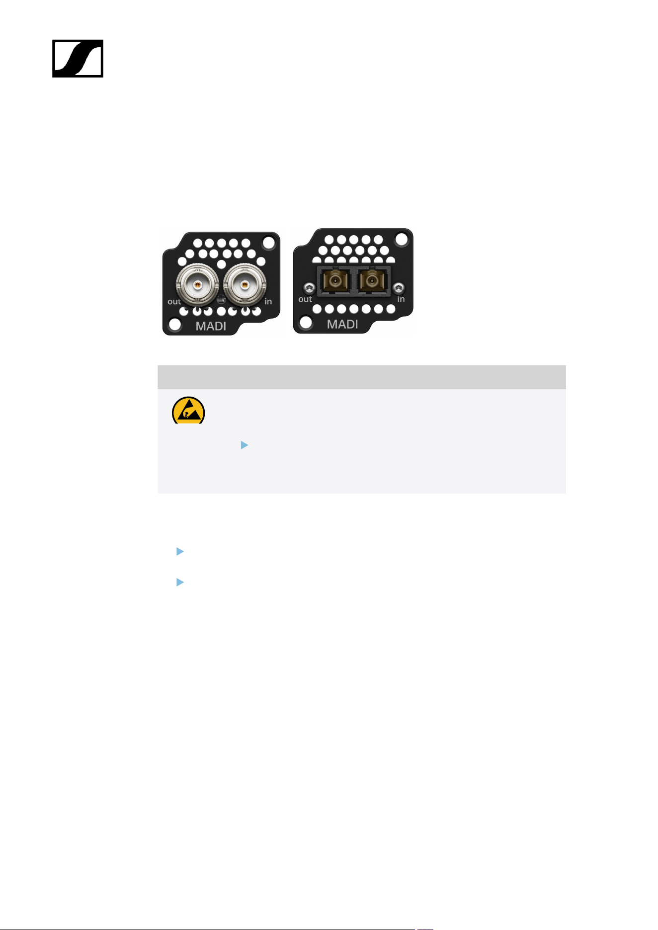
Installing slot-in cards
The same or different cards can be installed.
Two types of MADI Cards are available, see MADI Cards.
Madi CARD (BNC) Madi CARD (OM)
CAUTION
Improper handling of the device may result in its damage
Device contains sensitive electronics to electrostatic discharge (ESD).
Observe the precautionary measures for handling components
at risk of electrostatic discharge and take appropriate protective
measures when touching the device.
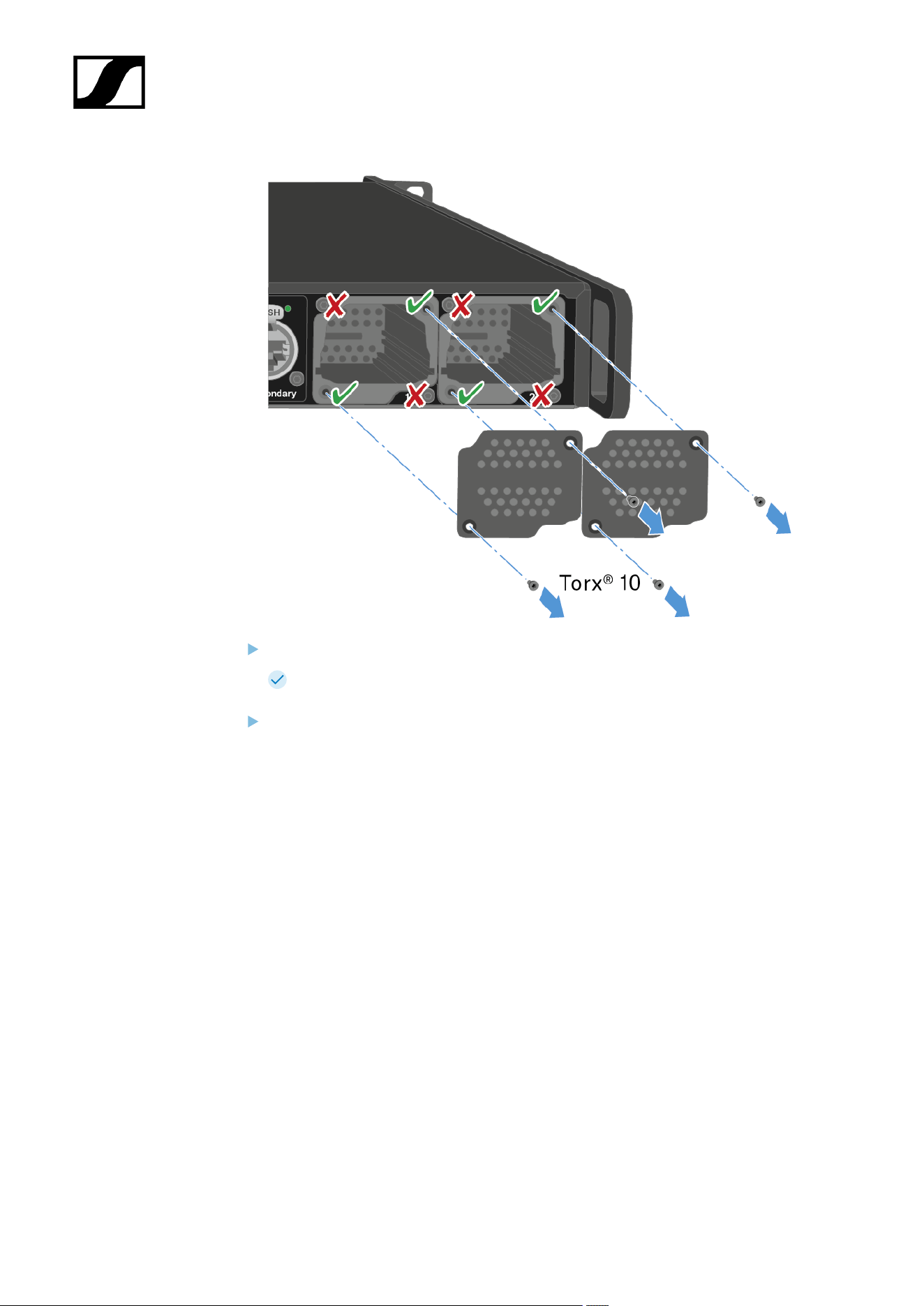
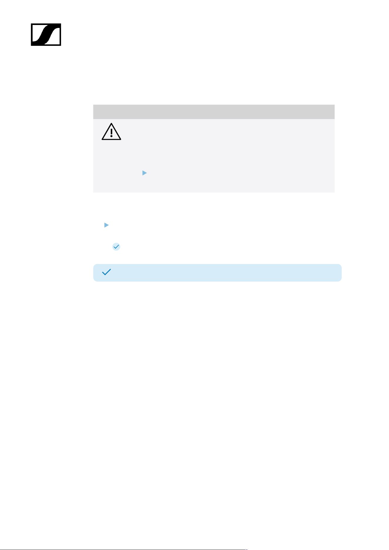
To install a MADI Card in the Base Station:
Completely disconnect the Base Station from the power supply system. See
Connecting/disconnecting the Base Station to/from the power supply system.
Unscrew one of the dummy caps on the Base Station. To do so, you require a torx® 10
screwdriver.
32
| 4 - User manual
Fully slide the MADI Card into the open slot as shown in the figure.
The card can be inserted into the Base Station housing only in one direction. The
lettering on the card must face upward.
Tightly screw on the MADI card with max. 65 cNm +/-10%.
33
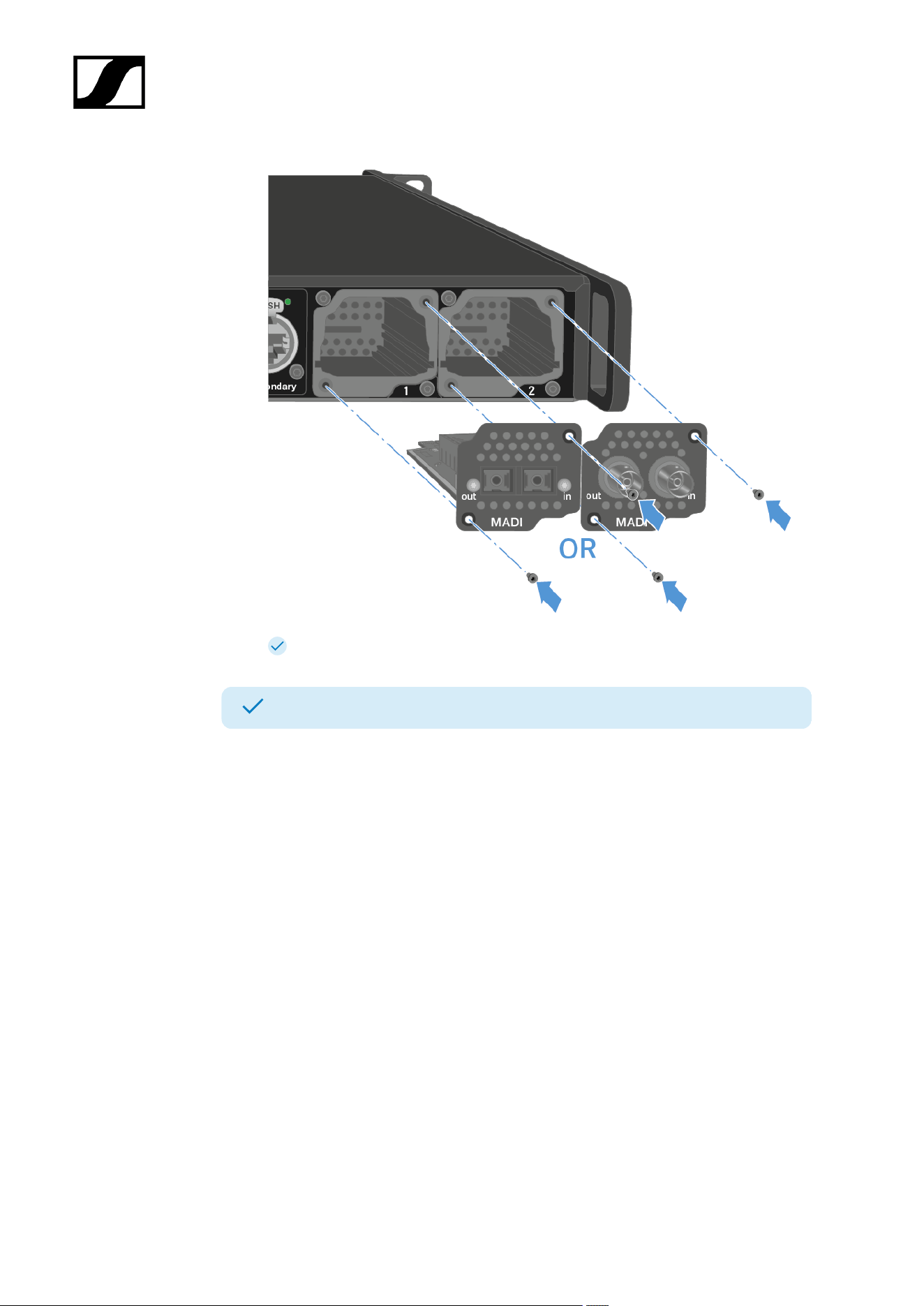
| 4 - User manual
The MADI Cards can be used directly.
A MADI Card has been installed.
34
| 4 - User manual
Connecting/disconnecting the Base Station to/from the power
supply system
Optional for redundancy you can connect the Base Station with two cables. The optional
cable is not included.
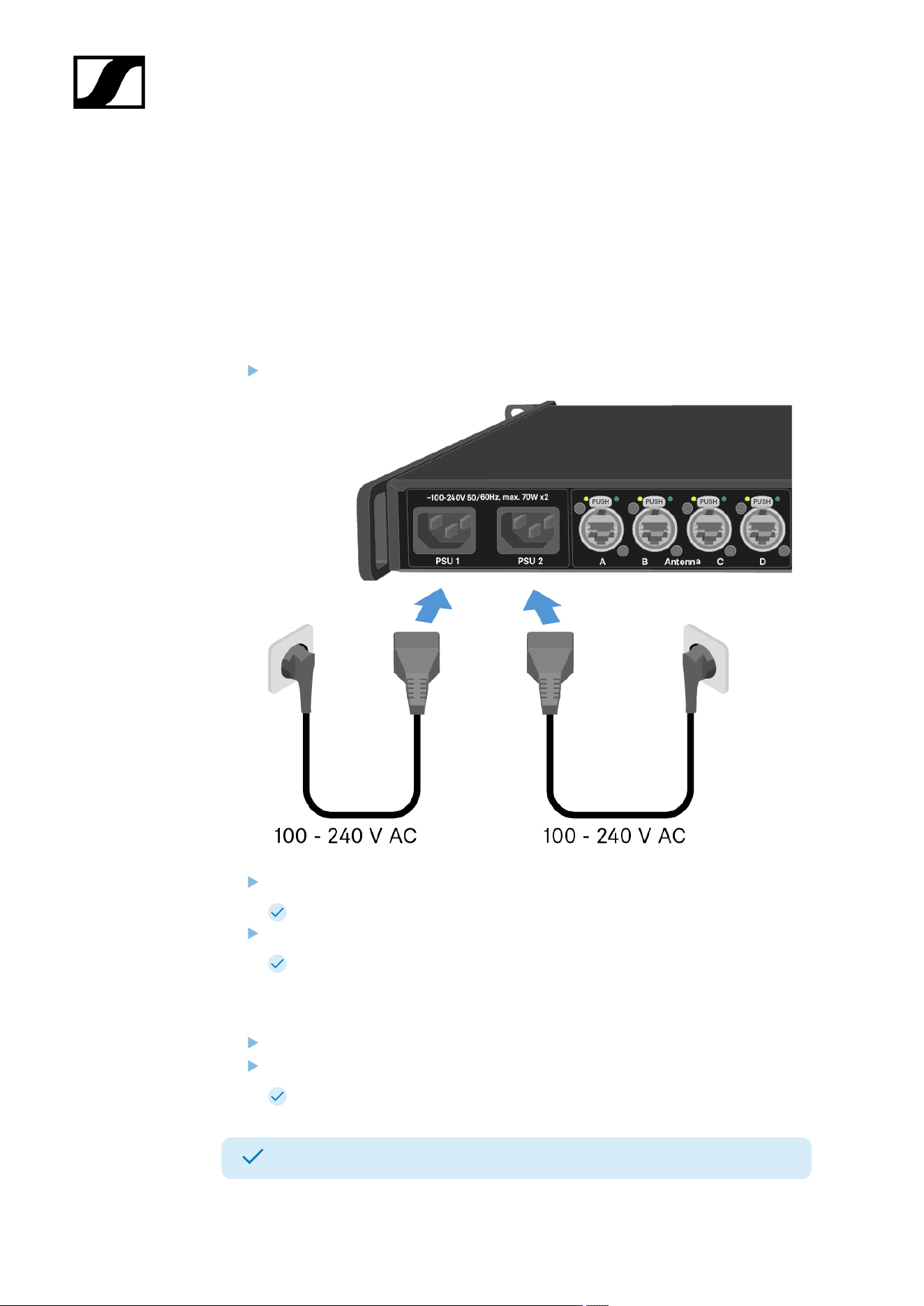
To connect the Base Station to the power supply system:
Connect one mains cable to the power socket on the rear side of the Base Station.
Connect one mains cable plug into a suitable wall socket.
The last state is restored: on or standby.
For redundancy connect an other cable (not included) as well.
The Base Station is connected to the power supply.
To completely disconnect the Base Station from the power supply system:
Unplug both mains cable plugs from the wall socket.
Unplug both mains cable from the power socket on the rear side of the Base Station.
The Base Station is completely disconnected from the power supply.
The Base Station has been connected/disconnected successfully.
35
| 4 - User manual
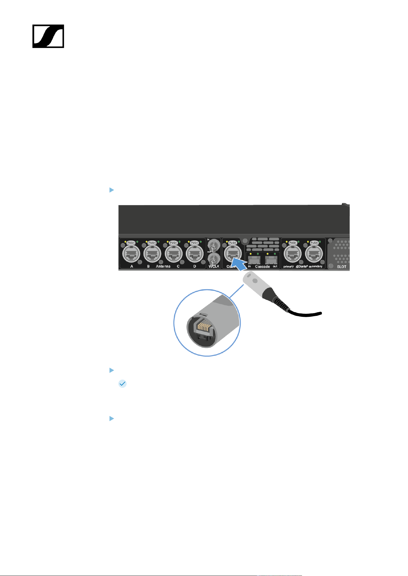
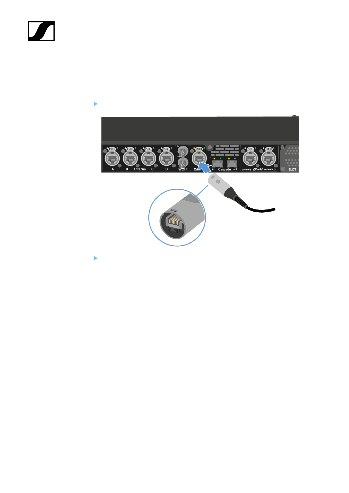
Connecting to a network
Connect the Base Station to a network for monitoring and controlling.
To connect the Base Station to a network:
Plug one side of the network cable into the Control socket.
Plug the other side of the network cable to a switch, router or directly to a computer.
36
| 4 - User manual
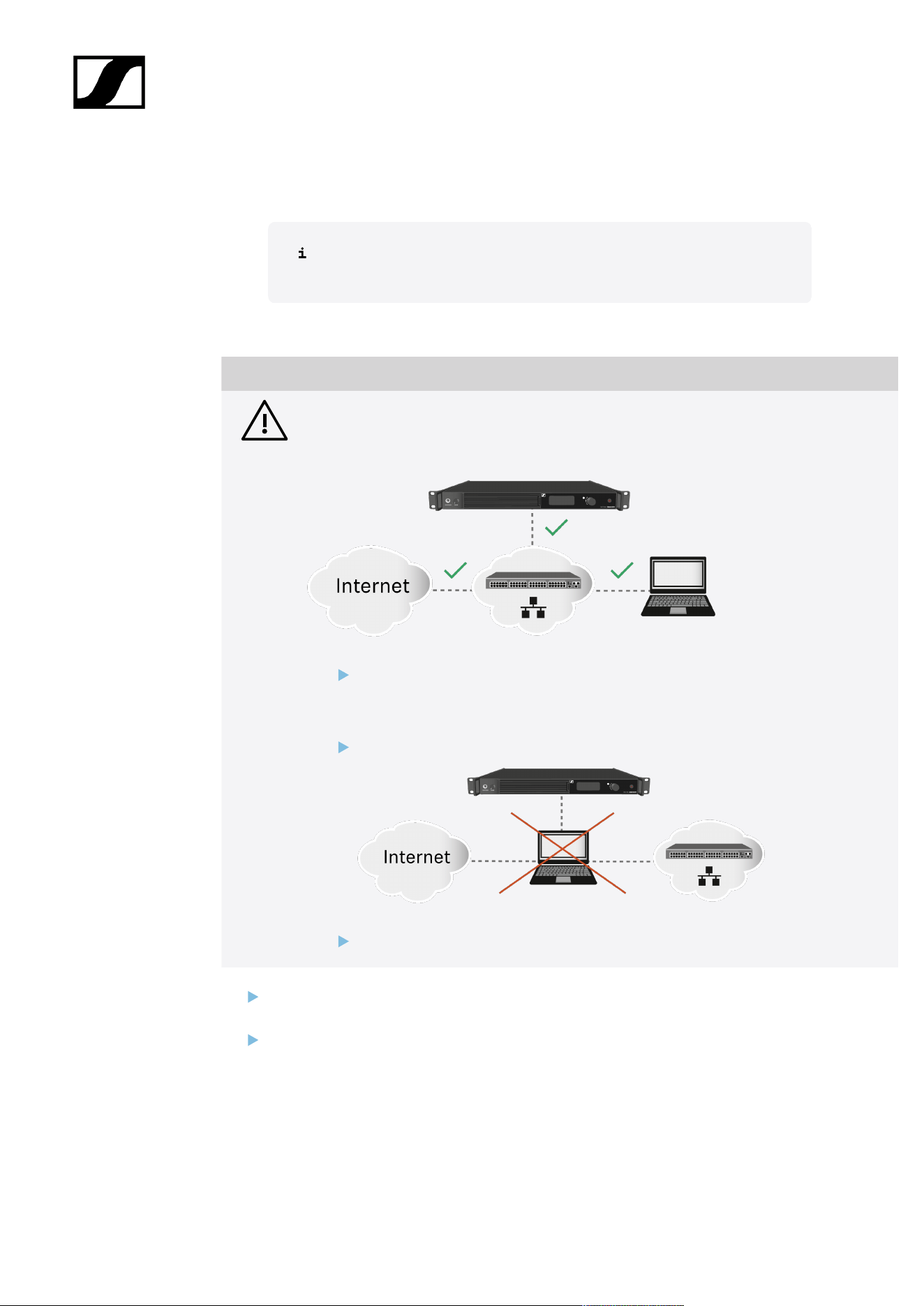
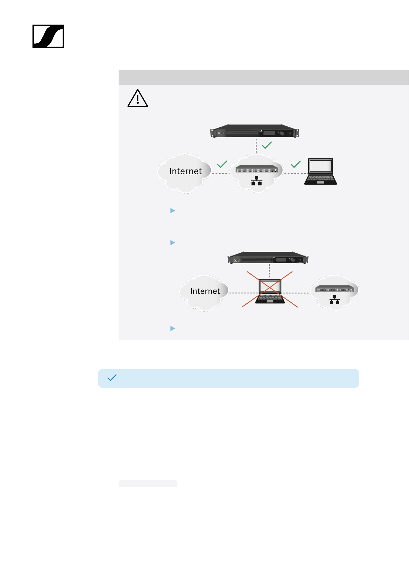
NOTICE
License activation requires a direct Internet connection to the device
In order to activate the Base Station using the 18-digit license code, a direct Internet
connection is required.
Please connect your Base Station directly to a network with Internet access via
a switch or router. For more information, refer to the chapter Connecting to a
network.
Direct connections via laptop etc. are not supported for activation!
The Internet is only required once for activation.
See Activating a license (general).
The Base Station has been connected to a network.
You can monitor and control the Base Station via a network connection using LinkDesk or
Spectera WebUI.
LinkDesk is freely available and can be downloaded directly from the Sennheiser website.
• sennheiser.com/linkdesk
To start the Spectera WebUI, enter the following URL into your browser:
• https://deviceIP
37

| 4 - User manual
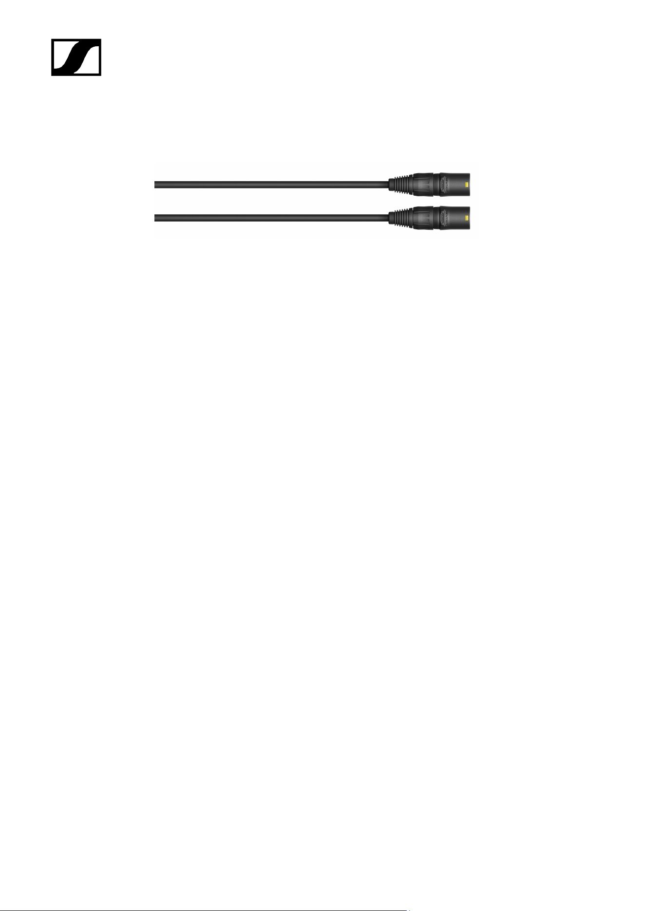
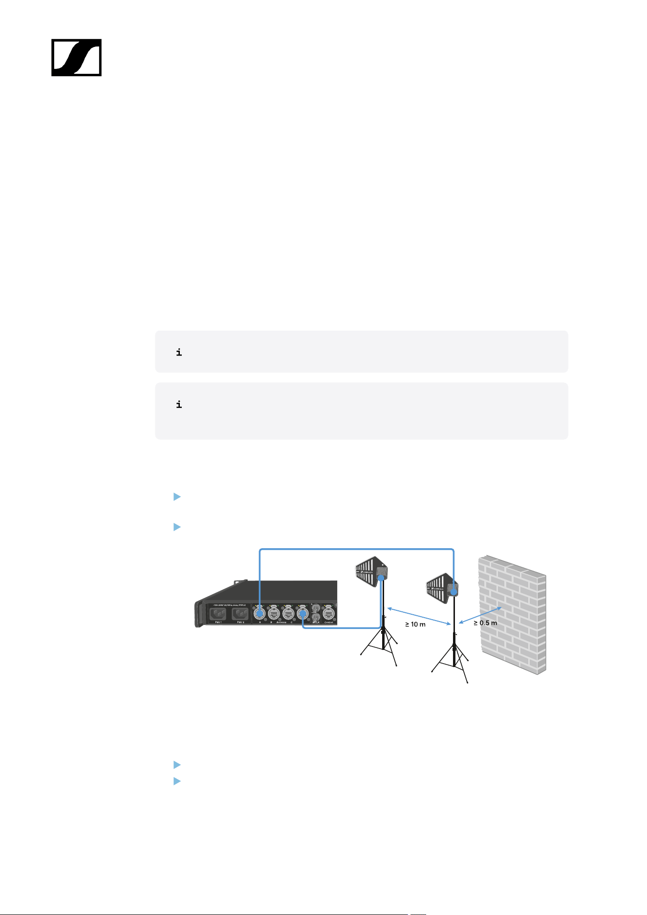
Connecting antennas
You can connect up to four antennas to the Base Station.
Recommandations regarding the antenna setup:
• Keep a distance more than 10 m (393.7") between the antenna and another antenna.
• Keep a distance more than 0.5 m (19.69") between the antenna and a wall.
The cable must
• be a CAT5e or higher,
• have ruggedized plugs and
• not extend 100 m (3937").
We recommend using a antenna cable cat 5e (see Accessories for the DAD).
Both variants (UHF and 1G4) can be connected to the Base Station at the same
time.
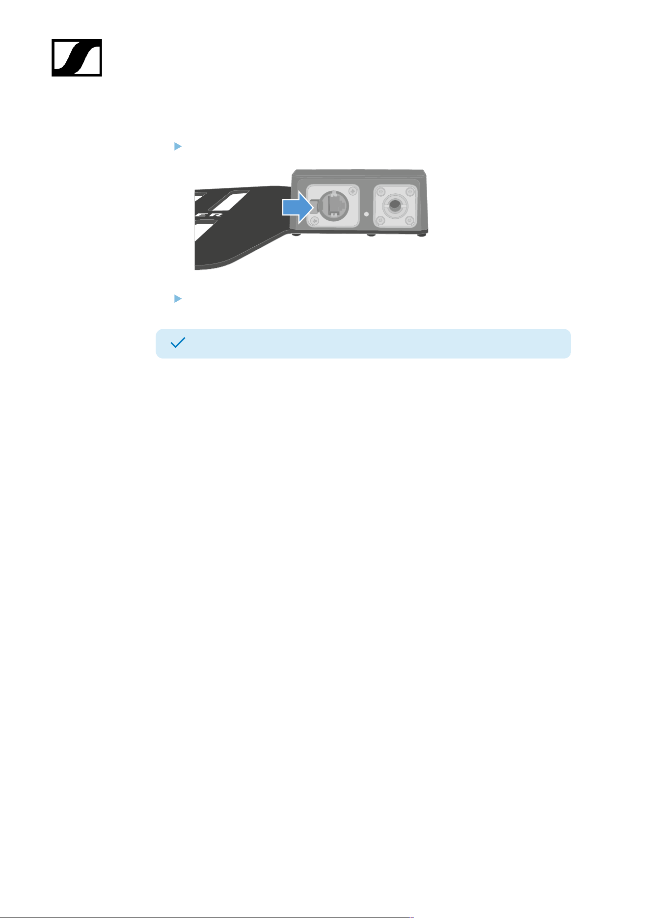
To connect an antenna to the Base Station:
Plug on side of the cable into one antenna port (A, B, C or D) at the rear side of the
Base Station.
Plug the other side of the cable into an antenna.
We recommend a distance greater than 10 m (393.7") for an optimal RF performance.
To disconnect an antenna from the Base Station:
Hold down the push button.
Unplug the cable from the Base Station.
39
| 4 - User manual
The Base Station has been connected to/disconnected from an antenna.
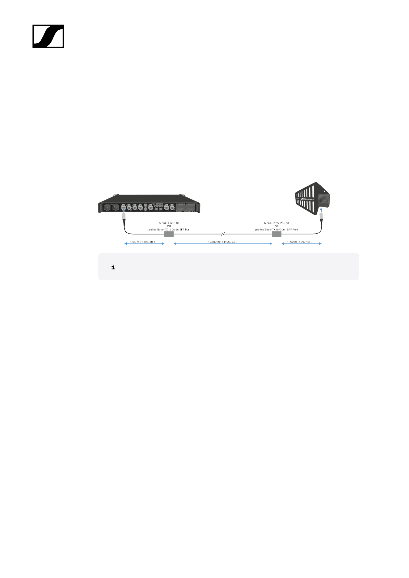
Antenna cable extension
Longer cable distances are possible with the use of fiber optic cables and media
converters.
Sennheiser tested the recommend converters for a complete distance of 4 km (157480.31").
We only recommend the following converters for fully tested functionality:
• Converter with PoE for DAD antenna Lantronix M/GE-PSW-PSE-01
• Converter for the Base Station Lantronix M/GE-T-SFP-01
• Converter for DAD antenna or Base Station proline Base-TX to Open SFP Port POE
The media converter must not have a switch function.
40
| 4 - User manual
Connecting word clock
You can use the internal word clock on the Base Station or connect an external word clock.
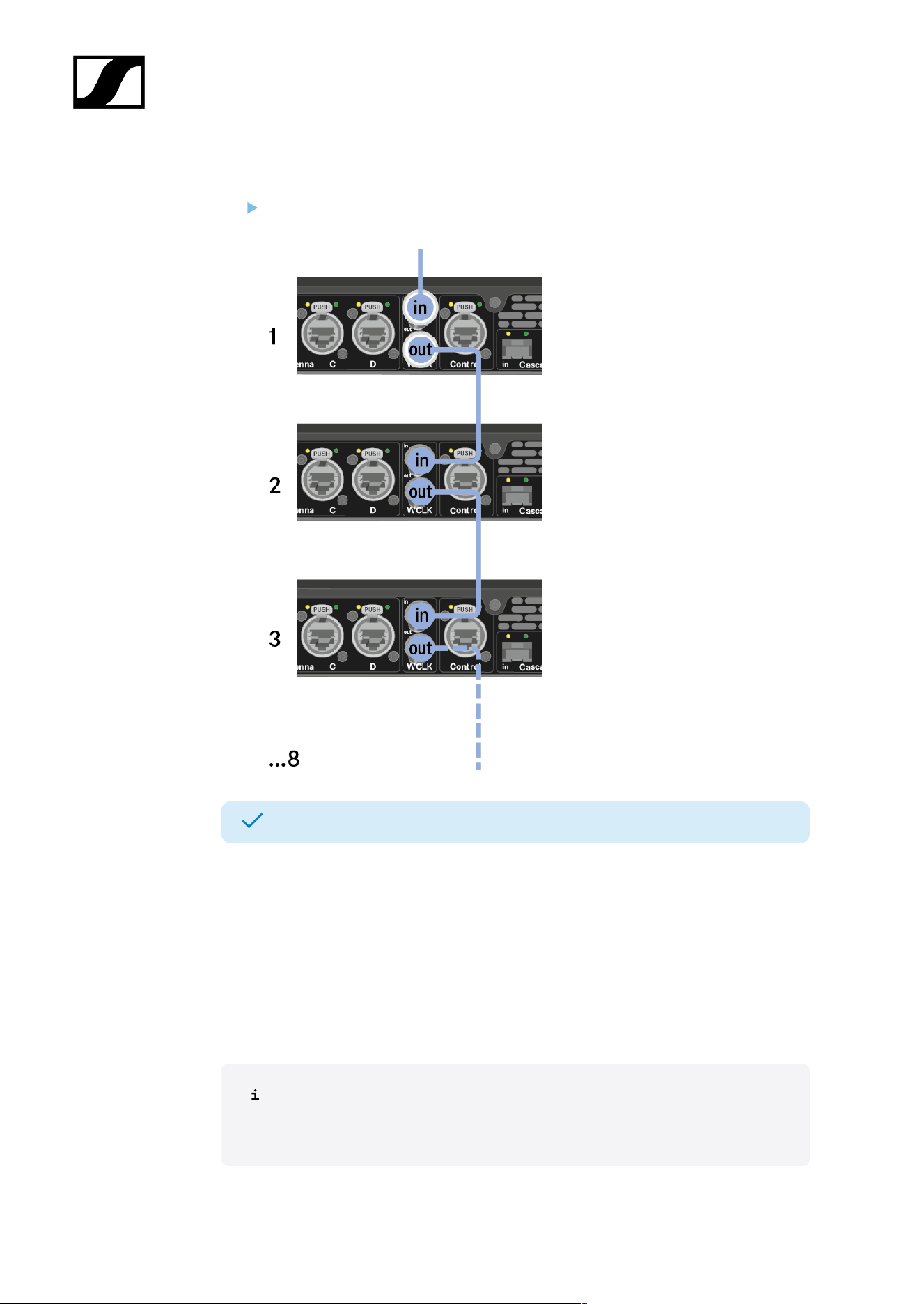
You can also output the external word clock and cascade it up to 8 Base Stations.
The word clock output transmits only the external word clock that is connected via the word
clock input. The internal word clock is not output via the word clock output.
For more information about the word clock, see Word clock scenarios for digital
audio.
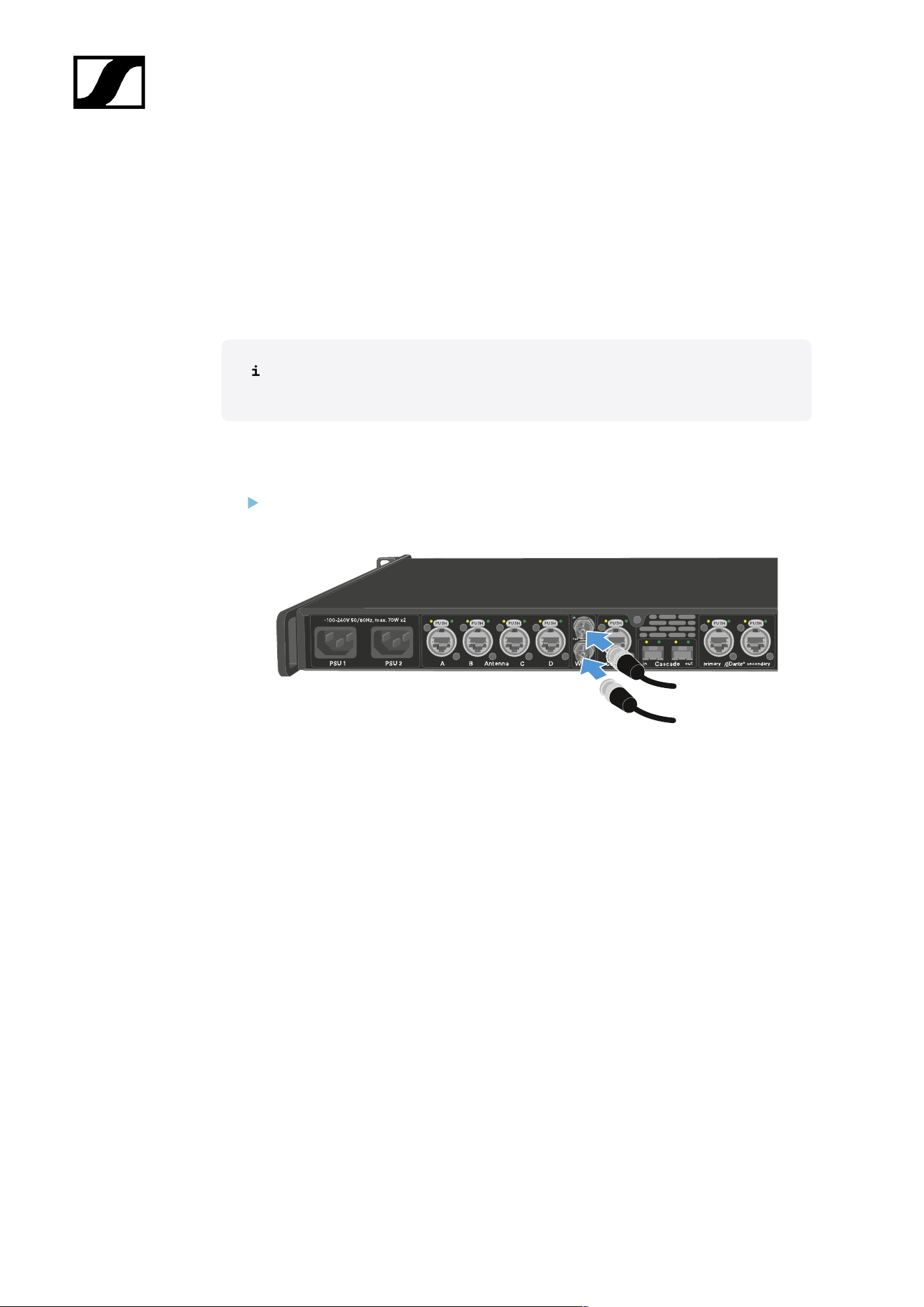
To connect an external word clock:
Use a coaxial BNC cable (75 Ω) to connect the external word clock to the word clock
in input.
41
| 4 - User manual
To cascade the word clock:
Connect the cable from the word clock in input of the next Base Station to the word
clock out output of the previous Base Station.
The Base Station has been connected to word clock.
Word clock scenarios for digital audio
The Base Station supports two clock rates: 48 kHz and 96 kHz.
You can use either the internal word clock on the Base Station or connect an external word
clock.
An external word clock can also be forwarded to a downstream device via the word clock
output. This feature allows you to cascade up to 8 Base Station devices.
Note that only the word clock on the word clock input can be forwarded via the
word clock output. The internal word clock is not forwarded via the word clock
output.
42
| 4 - User manual
Word clock with digital audio
If multiple devices with digital audio signals are connected in a production environment,
their clock signals must be synchronized via a word clock, otherwise audio errors occur. The
word clock of one device becomes the master. All of the other devices become slaves and
synchronize with the master.
Dante®
The Audinate Brooklyn III Dante® interface installed in the Base Station should be understood
as a standalone digital audio device with its own word clock and also has to be clocked either
internally or externally.
You require the Dante Controller software from Audinate for these settings. You
can access it using the link: Dante Controller.
Defining the master and slave
The Base Station word clock input, the Base Station internal word clock, the word clock
of the Audinate Brooklyn III Dante® interface, or the Dante® network can be defined as the
master.
For LinkDesk see: Configuring interface settings.
For WebUI see: Audio interfaces.
43
| 4 - User manual
Connecting audio via Dante®
You can input and output audio via Dante®.
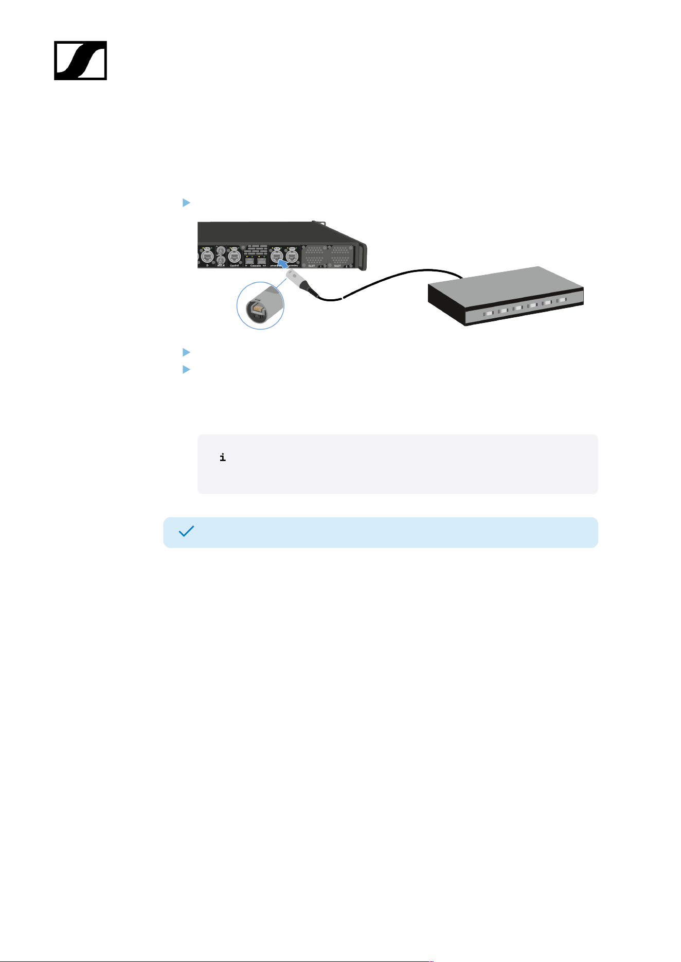
To connect audio via Dante®:
Plug one side of a ruggedized RJ45 cable to the Dante® primary socket.
Plug the other side into a router.
Download the Dante® Controller.
This is typically a host computer (PC or Mac), with the Dante® Controller software
application installed. This application configures and controls all the Dante® devices
and audio streams inside the network.
Information about the Dante Controller and the Dante® network protocol
settings is available on the Audinate website: audinate.com.
The Base Station can input and output audio via Dante®.
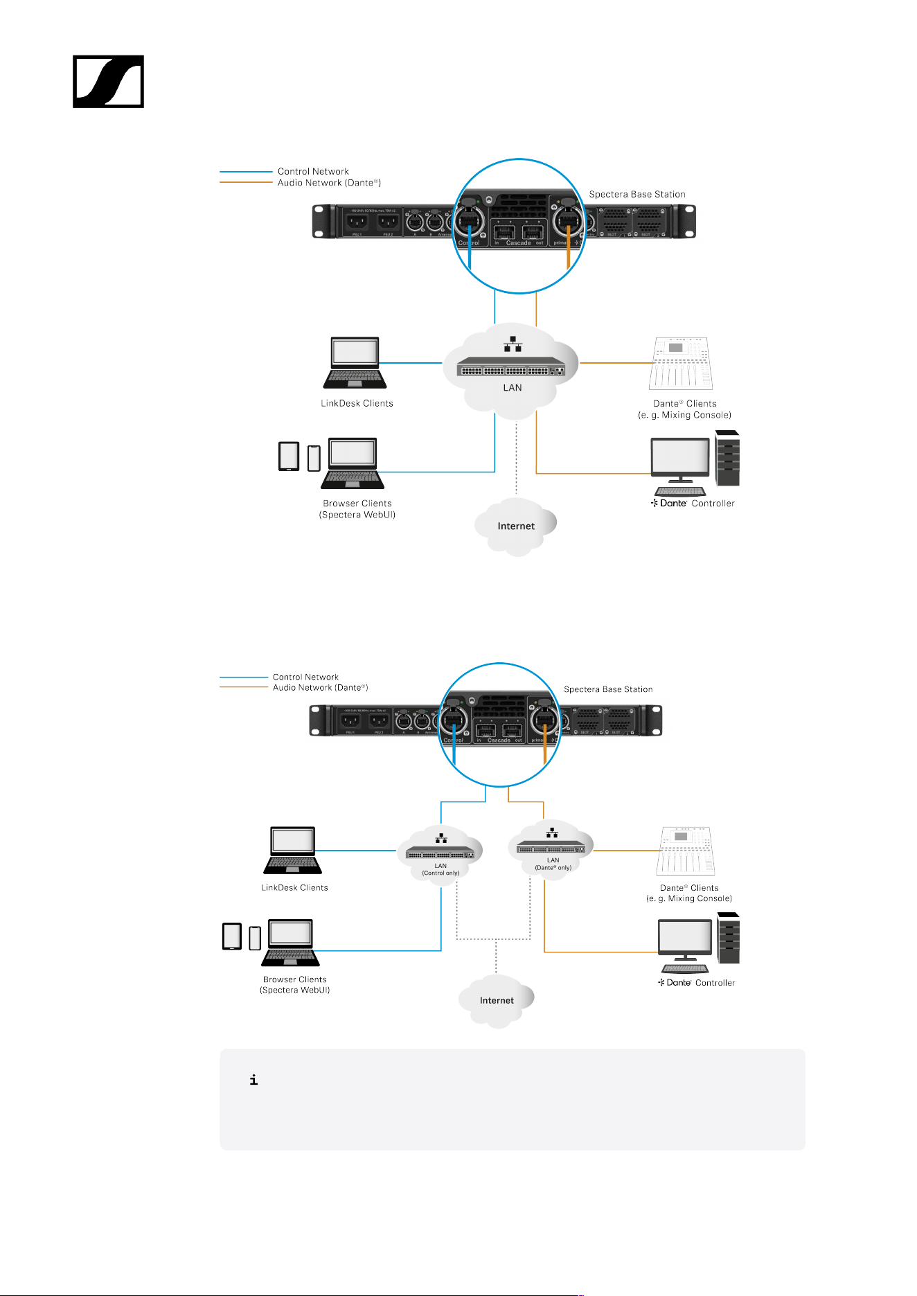
Shared network mode
In Shared Network Mode both networks for Control and Dante® are using the same physical
network infrastructure.
44
| 4 - User manual
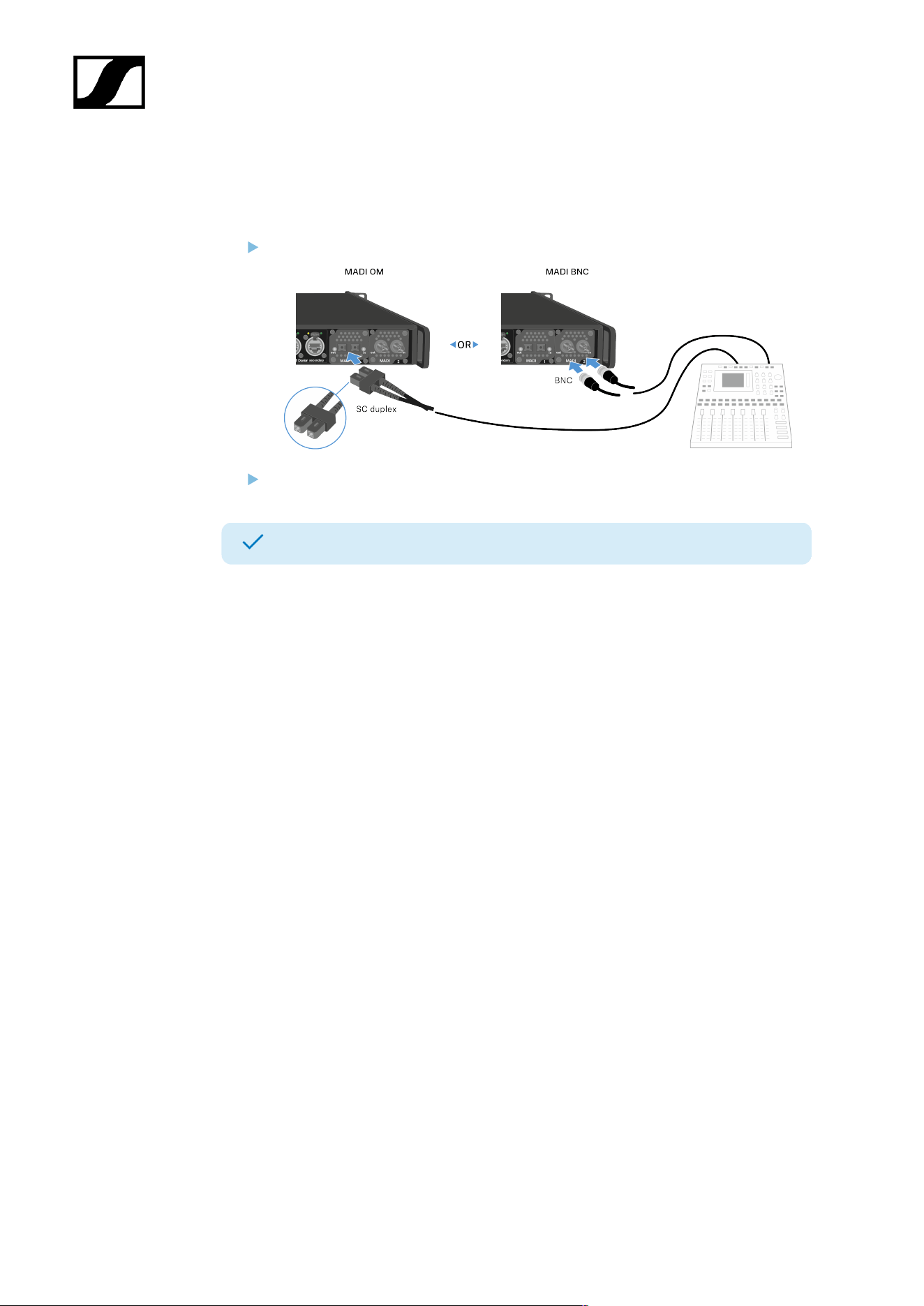
Split Network Mode
In Split Network Mode both networks for Control and Dante® are using different physical
network infrastructure.
For more information, please refer to the Network & Security Guide, which
can be found in the download section on the Base Station product page
sennheiser.com/base-station.
45
| 4 - User manual
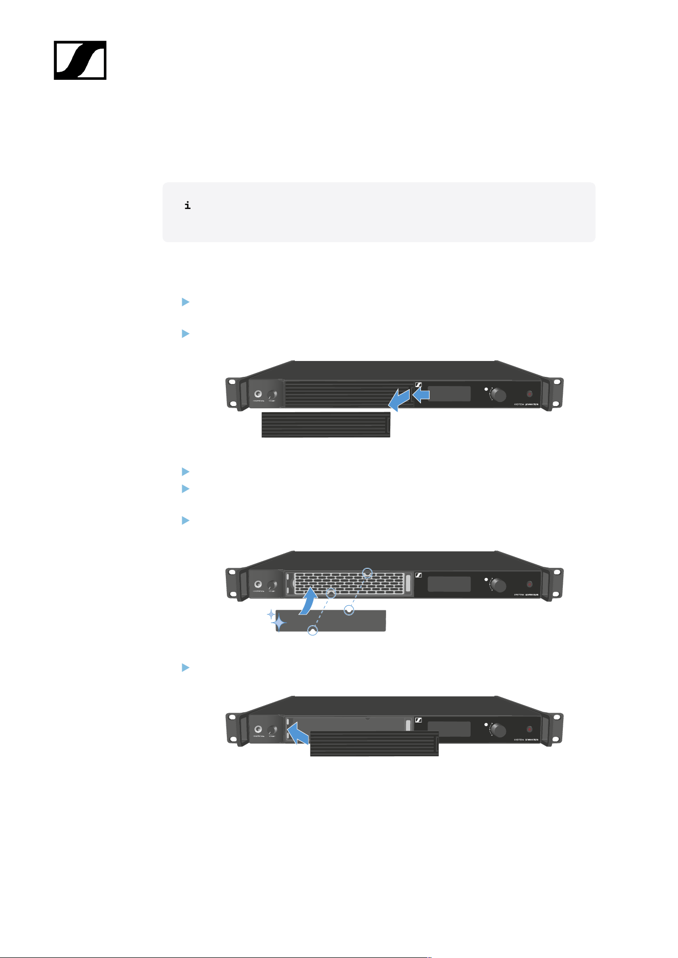
Connecting audio via MADI
To connect audio via MADI:
Plug one side of the (BNC or OM) cable to the installed MADI card.
Plug the other side of the cable to a mixing console.
The Base Station can input and output audio via MADI.
46
| 4 - User manual
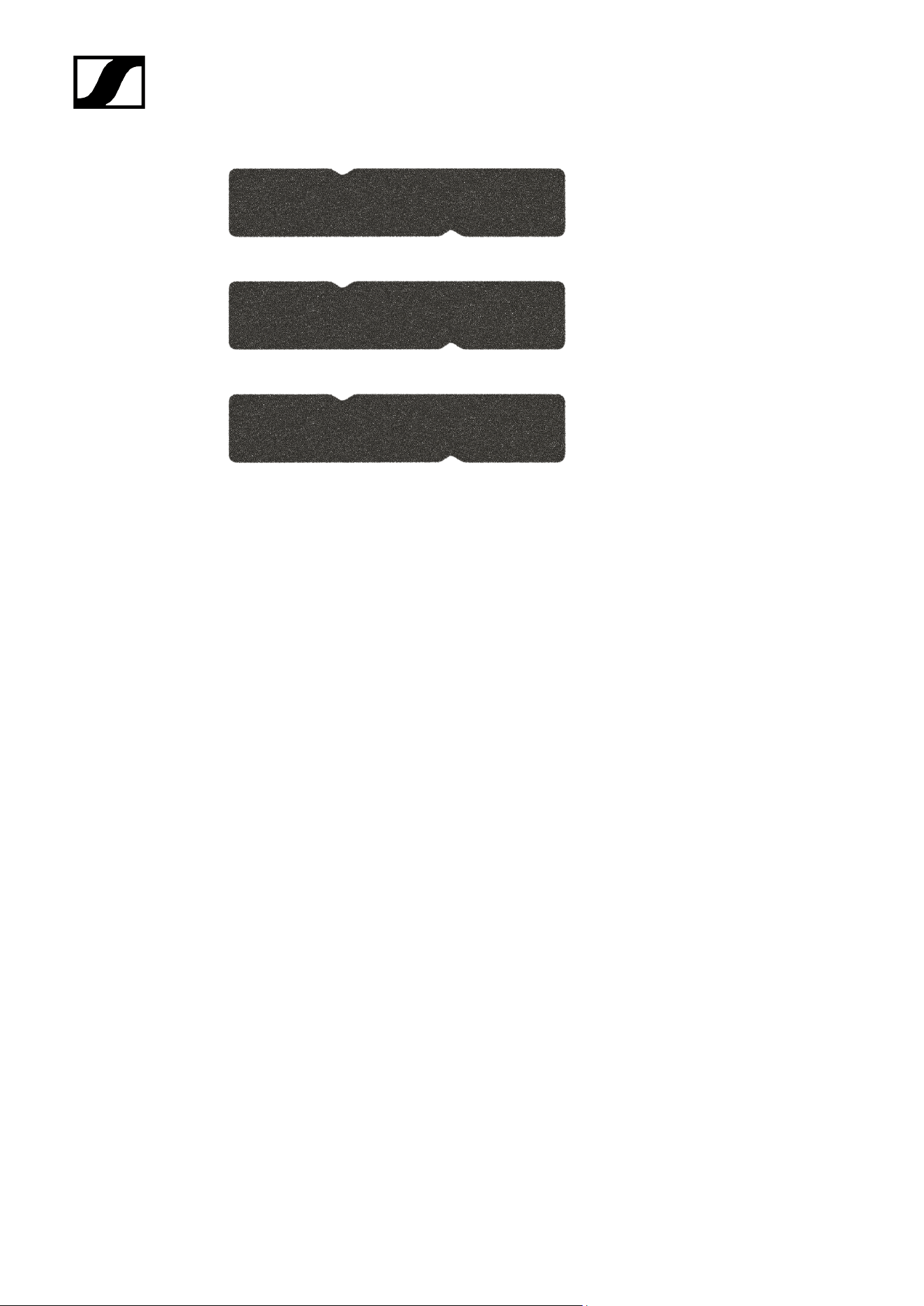
Changing the fan filter
The filter protects the fans from dust.
Check the filter from time to time and replace it to ensure safe operation and
sufficient cooling.
To change the filter:
Switch the Base Station into standby. See Switching the Base Station on and into
standby.
Push down the release and pull the cover forward at the same time.
Remove the filter and dispose it properly.
Place a new filter in the Base Station.
Information about new filter can be found here: Spectera Filter set.
Make sure that the recesses match those in the device.
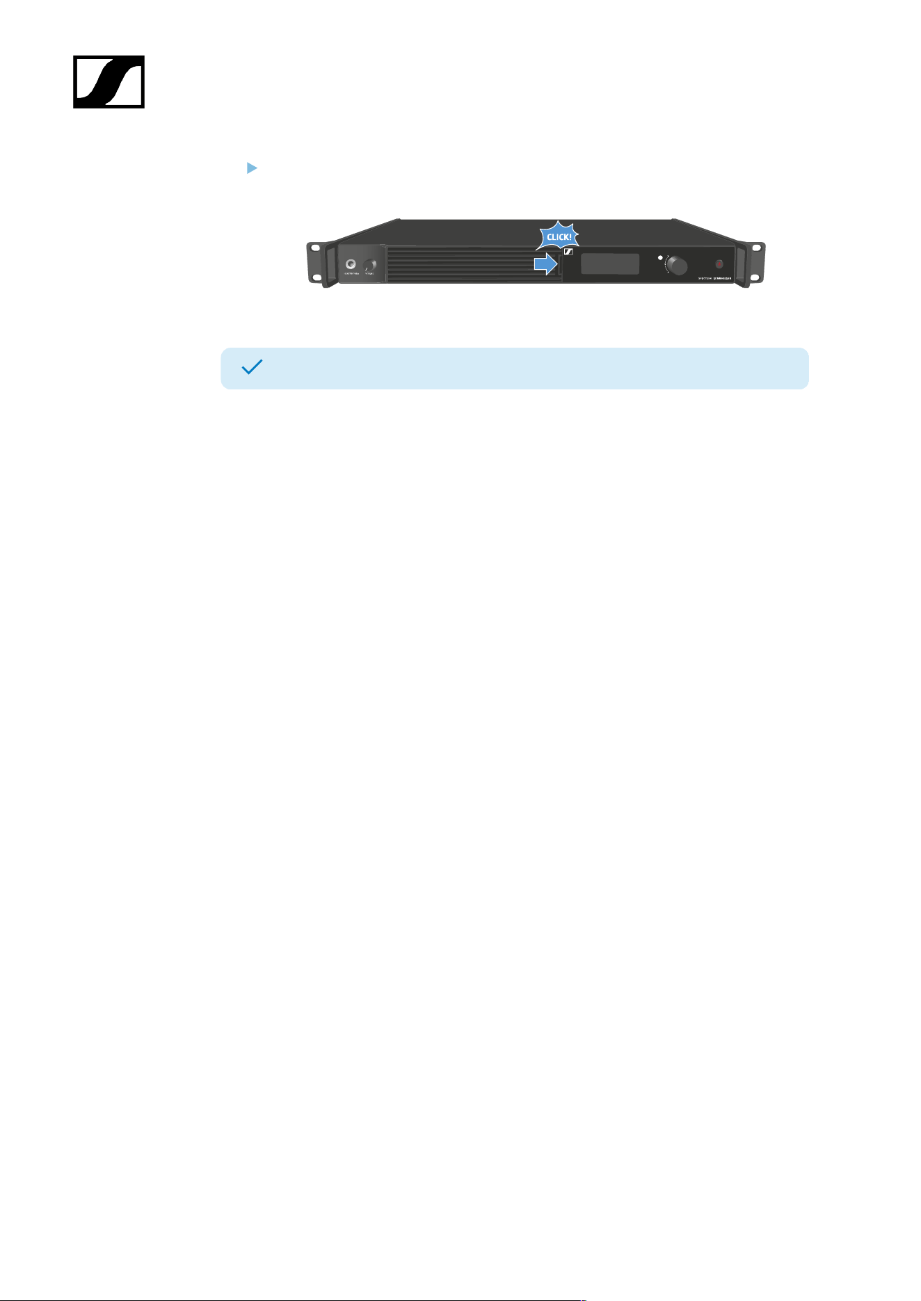
Slide the cover into the left side.
47
| 4 - User manual
On the right side, press the cover firmly until you hear it click into place.
The filter has been replaced.
48
| 4 - User manual
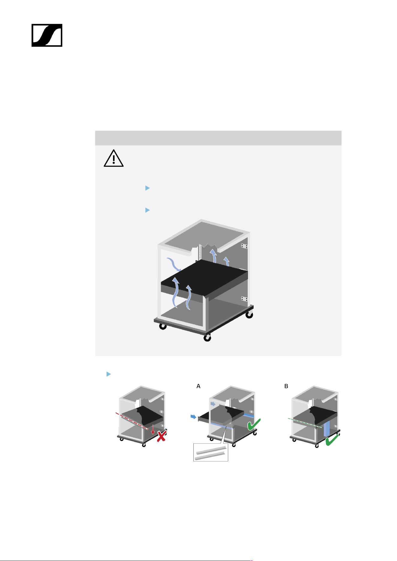
Installing the Base Station in a rack
You can install the Base Station in any conventional 19" rack. The rack mounting angles are
already attached to the device.
Always observe the following information during rack mounting.
NOTICE
Material damages caused by devices overheating
When there is insufficient ventilation, the devices mounted in the rack
may overheat.
Ensure that there is sufficient ventilation in the rack, particularly
if several devices are installed.
If necessary, install a fan in the rack.
Support the Base Station after installation in the rack.
Due to the weight and depth of the device, there is a risk that it may break off in the
rack and become damaged as a result.
49

| 4 - User manual
Version A
Use special rack mounting rails.
The design of the rack used must be suitable for the installation of these mounting
rails.
Version B
Use a suitable object to support the device on the rear side.
Ensure that this object cannot become loose.
The Base Station has been installed in a rack.
50

| 4 - User manual
Switching the Base Station on and into standby
The Base Station cannot be switched off. You have to disconnect it from the
power supply, see Connecting/disconnecting the Base Station to/from the
power supply system.
To switch the Base Station on:
Short-press the ON/OFF button.
The Sennheiser Logo appears in the display and the Base Station is booting.
When booting is done, the power button LED lights up white.
To switch the Base Station into standby:
Long-press the ON/OFF button.
The display and the LED go off. The ON/OFF button pulses white.
The DAD goes off.
The Base Station has been switched on/into standby.
51
| 4 - User manual
Activating a license (general)
A license has to be activated, otherwise you cannot use the Base Station.
NOTICE
License activation requires a direct Internet connection to the device
In order to activate the Base Station using the 18-digit license code, a direct Internet
connection is required.
Please connect your Base Station directly to a network with Internet access via
a switch or router. For more information, refer to the chapter Connecting to a
network.
Direct connections via laptop etc. are not supported for activation!
The Internet is only required once for activation.
The license specifies the country-specific frequency ranges and the RF power.
You can activate a license via LinkDesk or Spectera WebUI.
Only one license per Base Station is possible.
To activate a license:
Connect the Base Station to the power supply, see Connecting/disconnecting the
Base Station to/from the power supply system.
Connect the Base Station to a network via a switch or router, see Connecting to a
network.
52

| 4 - User manual
The Base Station needs a direct Internet access!
Connect a computer to the same switch or router.
If you want to activate a license via LinkDesk, follow the steps described here:
Activating a license (LinkDesk).
If you want to activate a license via Spectera WebUI, follow the steps described here:
Activating a license (webUI).
Check the product page sennheiser.com/base-station for the latest firmware.
A license has been activated.
53
| 4 - User manual
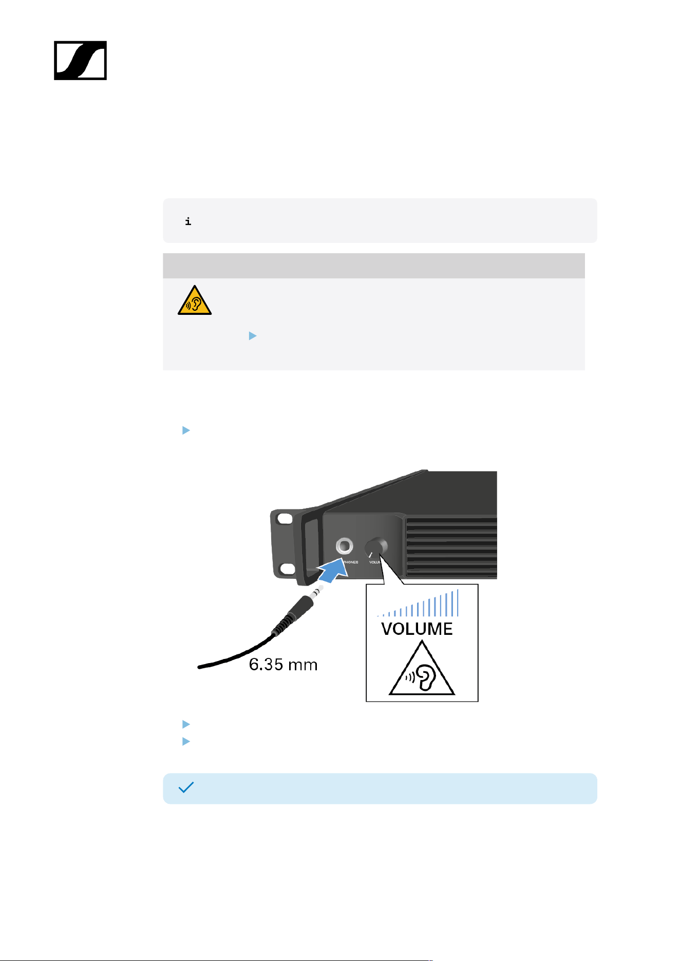
Using the headphone output
You can use the headphone output on the front of the Base Station (6.35 mm jack) to listen
to the audio signals of the channels.
First you have to set up audio links in LinkDesk or Spectera WebUI.
WARNING
Danger due to high volume levels
Volume levels that are too high may damage your hearing.
Turn down the volume of the headphone output before you put on
the headphone.
To listen to an audio source:
Connect the headphone to the HEADPHONES socket.
You can select the audio source here: Headphone.
Control the volume by turning the VOLUME control next to the HEADPHONES socket.
You can now listen to the selected audio source.
54
| 4 - User manual
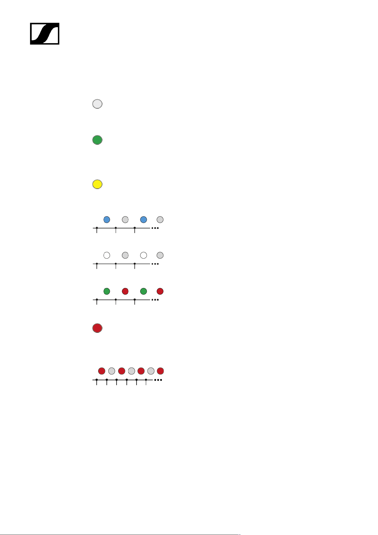
Meaning of the LED
The LED on the front of the Base Station indicates the following information.
The LED is off:
• Base Station is in standby.
The LED is green:
• Base Station is on and one or both RF channels are
active.
The LED is yellow:
• One or both RF channels are muted.
The LED is flashing blue:
• Paring is enabled.
The LED is flashing white:
• The Base Station is identified.
The LED is flashing green and red:
• Firmware update is in progress.
The LED is red:
• Base Station is working, but shows a warning on the
display.
The LED is flashing red quickly:
• Error. Base Station is not working and shows a warning
on the display.
55
| 4 - User manual
Information on the display
Basic information are shown on the display.
The display goes into screen saver after some time.
You can wake up the display by pressing or turning the jog-dial.
The display shows the operating menu, which can be used to configure a few settings (see
Menu structure).
More options and other parameters are available in LinkDesk and Spectera
WebUI!
To navigate the menu, see Navigating the menu.
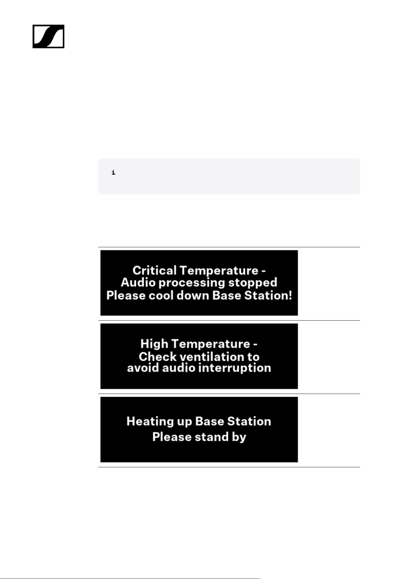
Status messages
In certain situations, status messages may appear on the display.
Error - The
temperature
is critical. The
audio processing
stopped. Cool down
the Base Station.
Warning - The
temperature is
high. Check the
ventilation to avoid
audio interruption.
Warning - The
temperature is low.
The Base Station is
heating up. Please
stand by.
56
| 4 - User manual
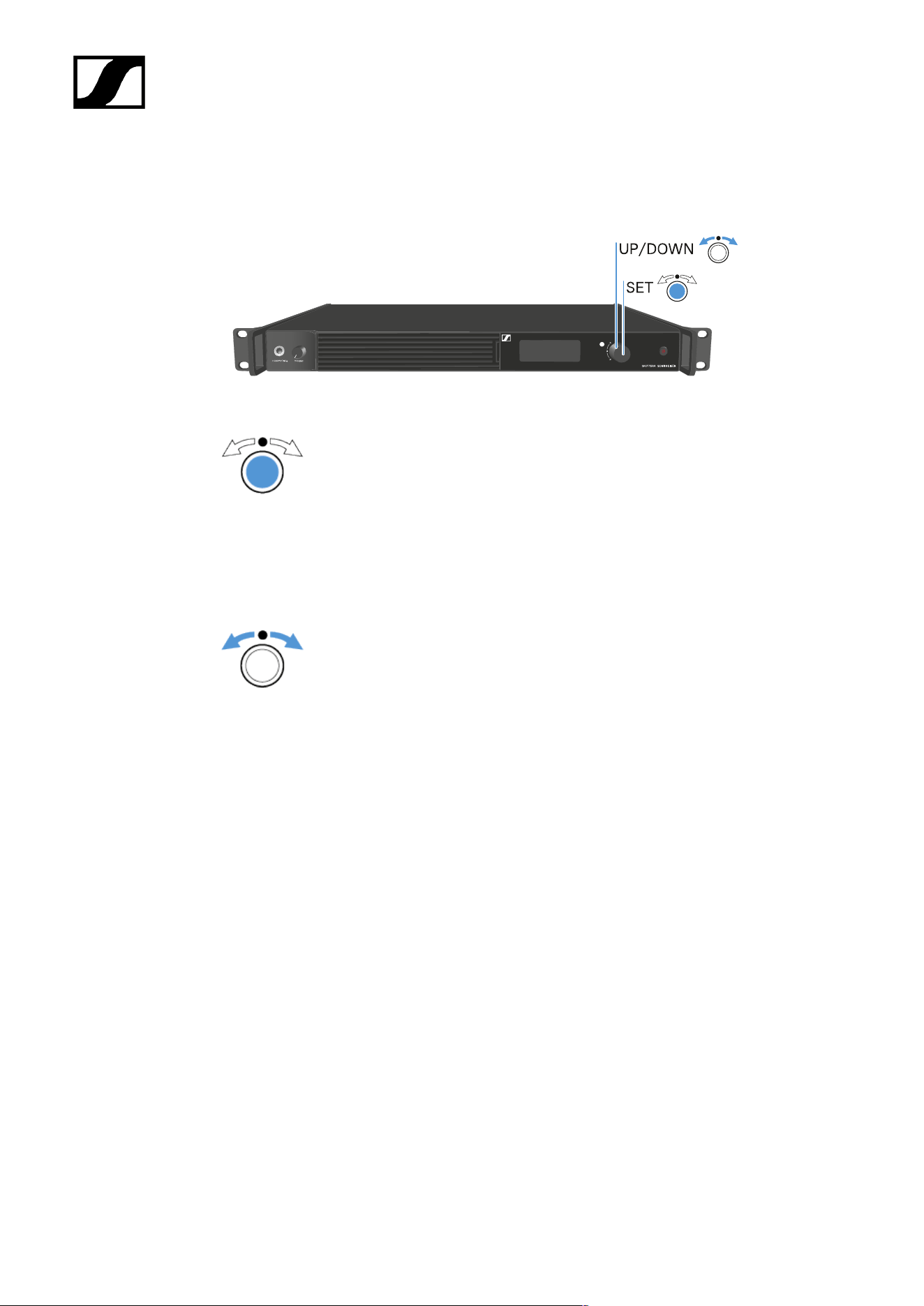
Navigating the menu
Use the jog-dial to navigate through the operating menu.
Press the jog dial
• Calls up a menu item
• Changes to a submenu
• Saves settings
Turn the jog dial
• Changes to the previous or next menu item
• Changes the setting of a menu item
57
| 4 - User manual
Menu structure
In the Base Station menu, you can configure a few settings.
More options and other parameters are available in LinkDesk and Spectera
WebUI!
The following settings can be changed:
Mute/Unmute the RF-Channels
• Main menu
Change the IP mode
• Network
Select the audio source for the headphone
• Headphone
Reset the Base Station
• Reset
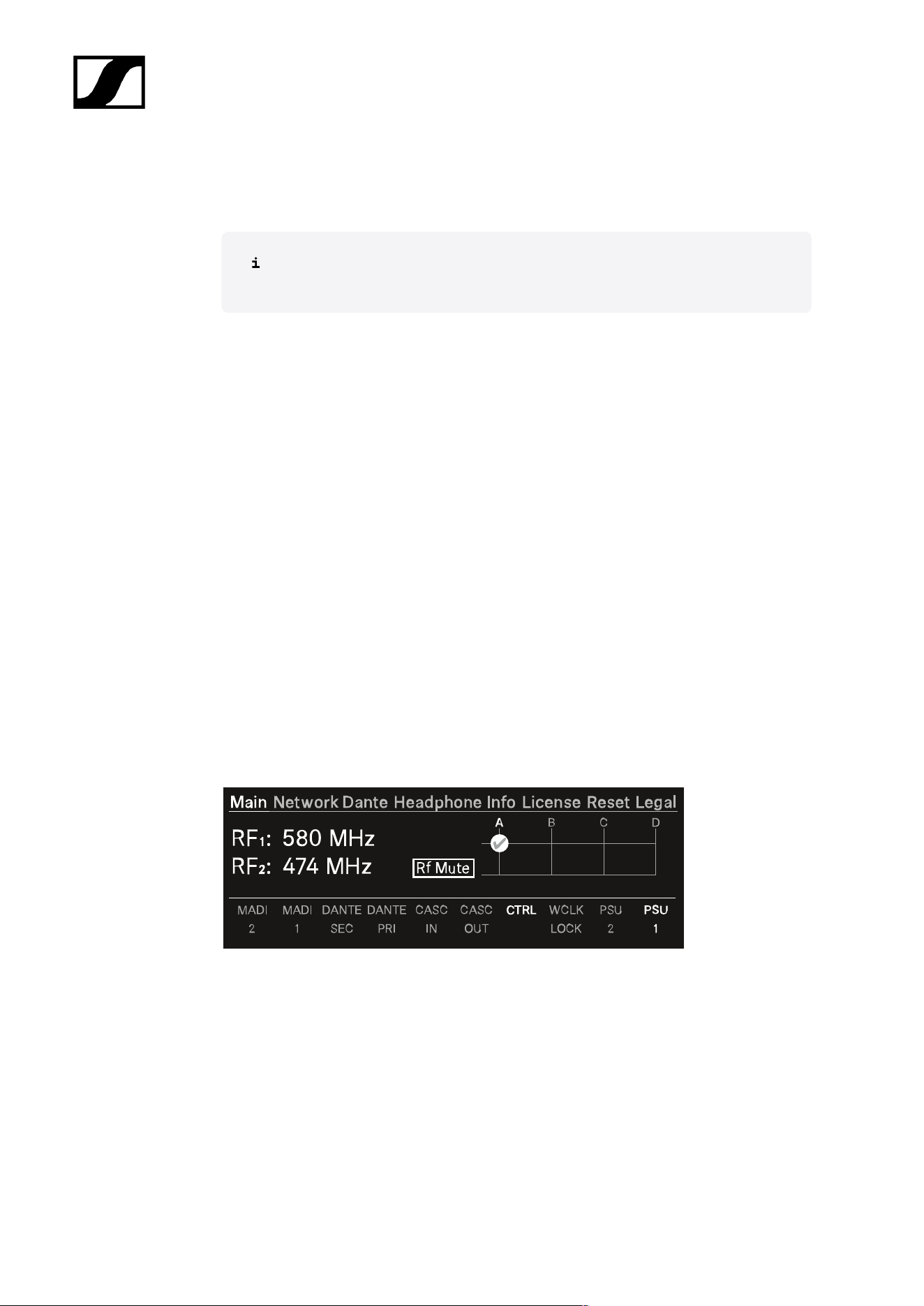
Main menu
In this menu item, you can view information about connections.
In the upper part you can view information about the RF channel:
• The selected frequency
• The state of the antenna (mute, active)
• Which antenna port is used for the RF channel.
In the lower part you can view information about the used connection:
• Connected ports are highlighted.
• The order corresponds to the ports on the back.
58
| 4 - User manual
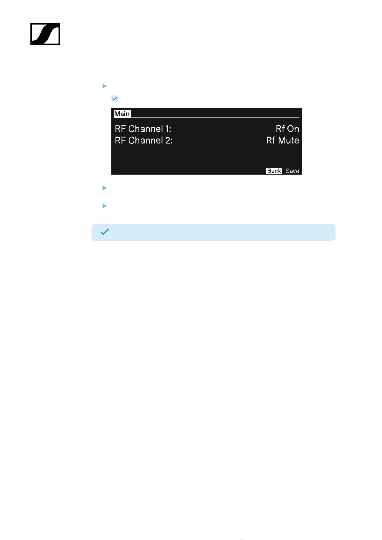
To mute/unmute the RF channel:
Press the jog-dial.
The RF Status menu opens.
Rotate and press the jog-dial to change the settings.
You can select between Rf on and Rf Mute.
Confirm by selecting Save or discard the changes by selecting Back.
The RF Channels have been muted/unmuted.
59
| 4 - User manual
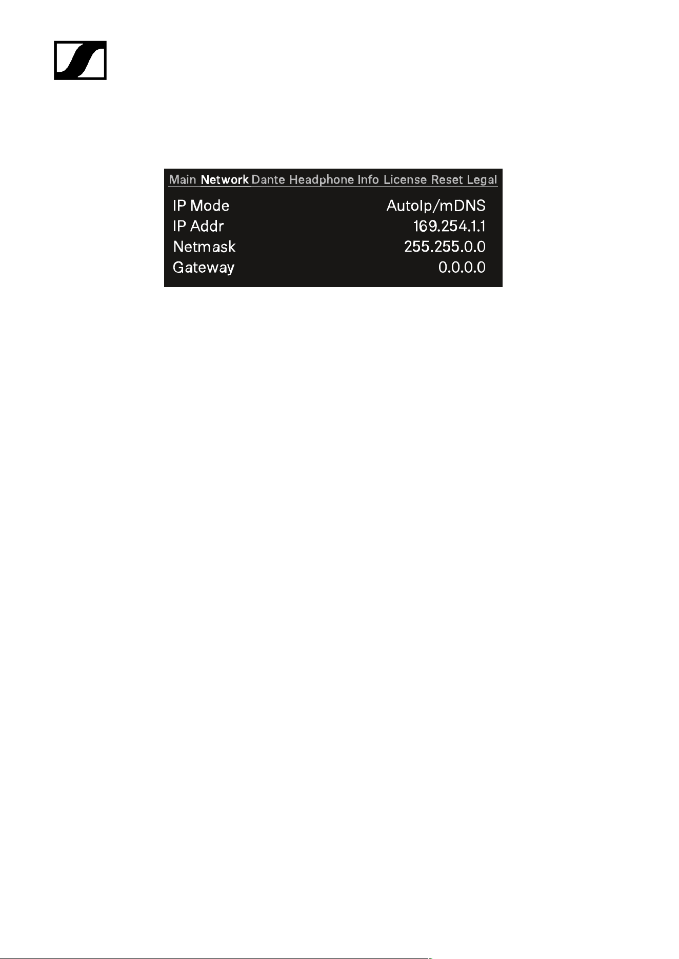
Network
In this menu item, you can configure the settings for the network connection.
You can make the following settings here:
IP Mode
• Manual
• You can change the IP Address, the Netmask and the Gateway.
• Manual/mDNS
• You can change the IP Address, the Netmask and the Gateway.
• AutoIp
• You can not change the IP Address, the Netmask and the Gateway.
• AutoIp/mDNS
• You can not change the IP Address, the Netmask and the Gateway.
60
| 4 - User manual
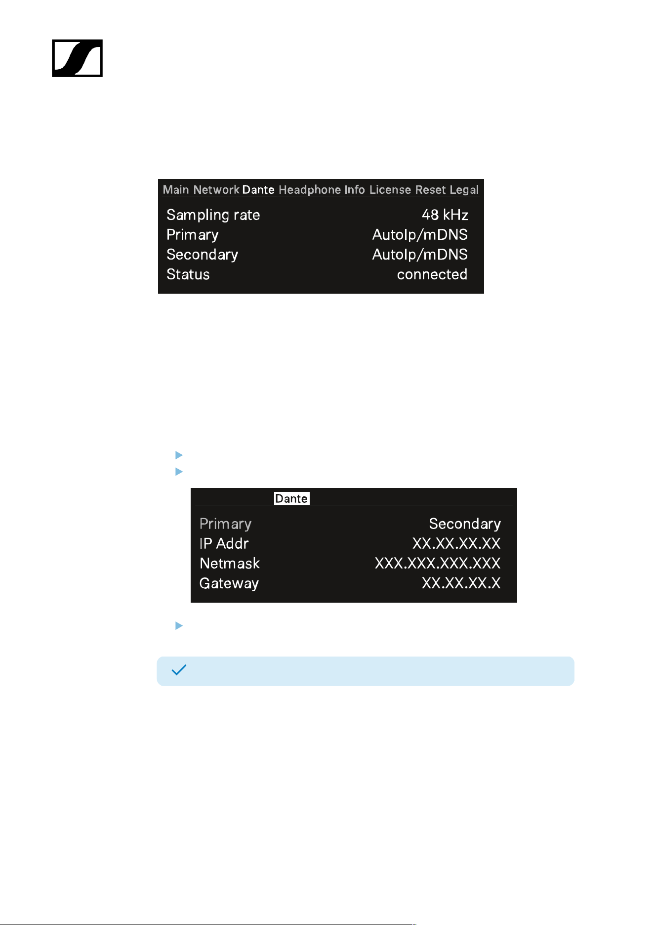
Dante
In this menu item, you can view information about the two Dante® connections.
The following information are displayed:
• Sampling rate
• IP mode for Primary
• IP mode for Secondary
• Status
To display a Dante® connection:
Press the jog-dial to change the Dante® connection.
Rotate the jog-dial to change between Primary and Secondary.
Press the jog-dial to enter the setting.
The selected Dante® connection is displayed.
61
| 4 - User manual
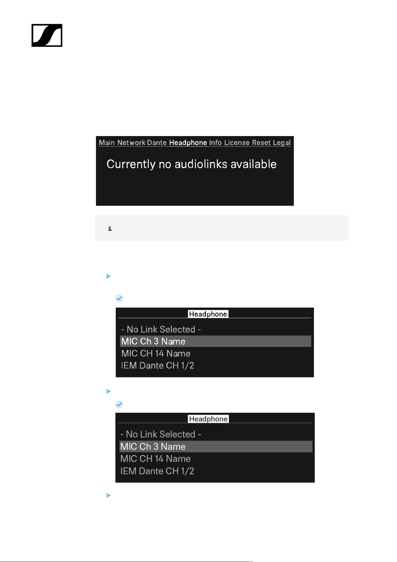
Headphone
In this menu item, you can select the headphone output.
You have to set up audio links via LinkDesk or Spectera WebUI for the mobile devices.
If no audio link is set this note will appear:
First you have to set up audio links in LinkDesk or Spectera WebUI.
To select an audio link:
Press the jog-dial to enter the headphone menu.
Each audio output will be shown independent.
The created audio links appear.
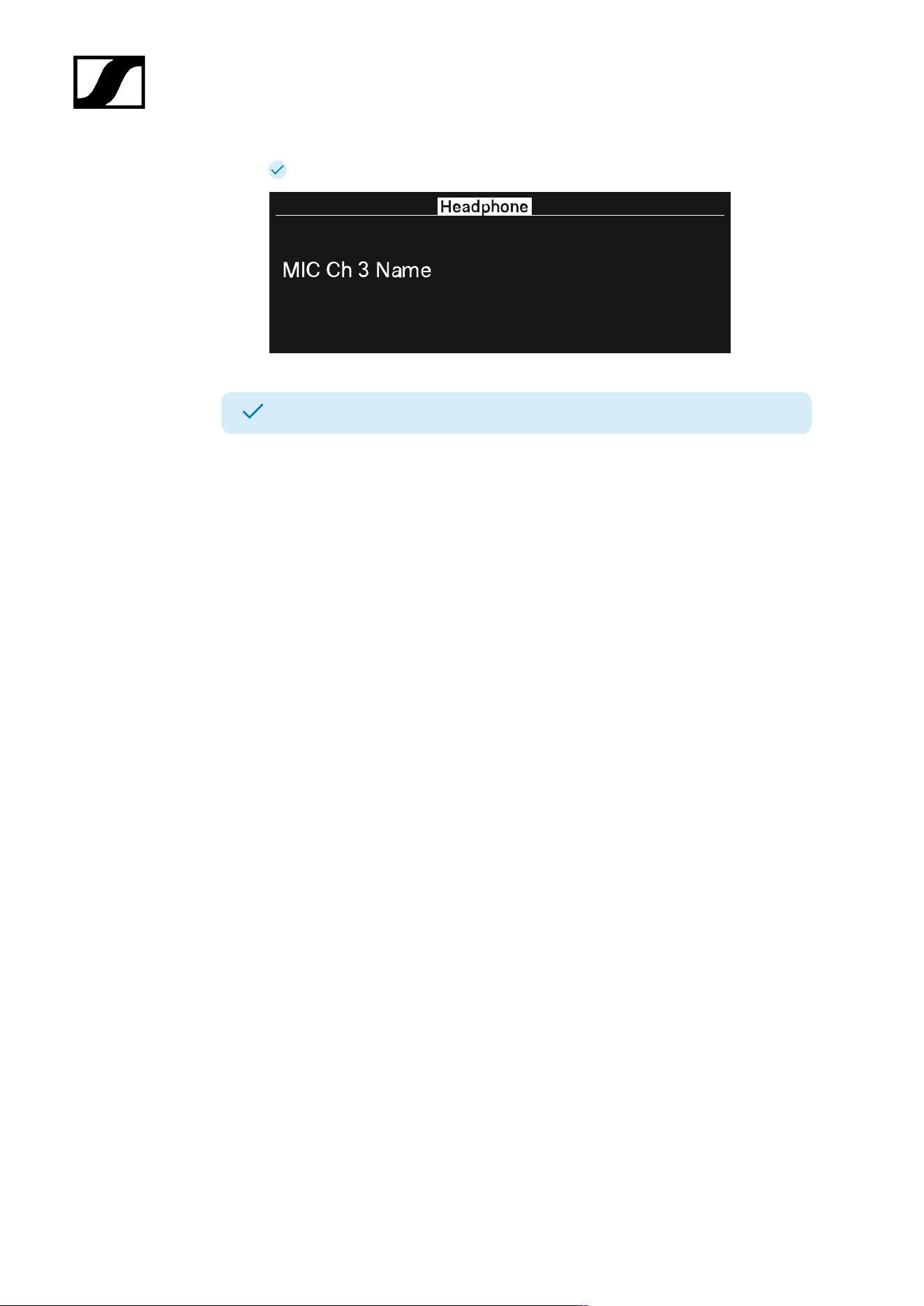
Turn the jog-dial to select the wanted audio link.
The name of the selected link pulses two times.
Press the jog-dial to return to the main menu.
62
| 4 - User manual
The selected link appears.
You can now listen to the selected audio link.
63
| 4 - User manual
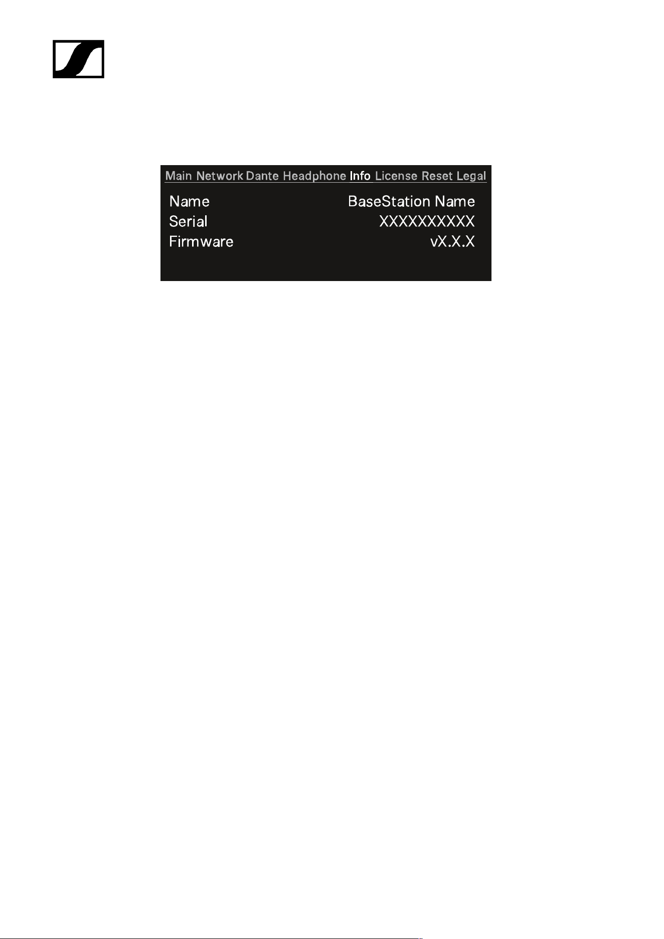
Info
In this menu item, general information can be shown here.
Name: The name of the Base Station.
Serial: The serial number of the Base Station.
Firmware: The installed firmware version.
64
| 4 - User manual
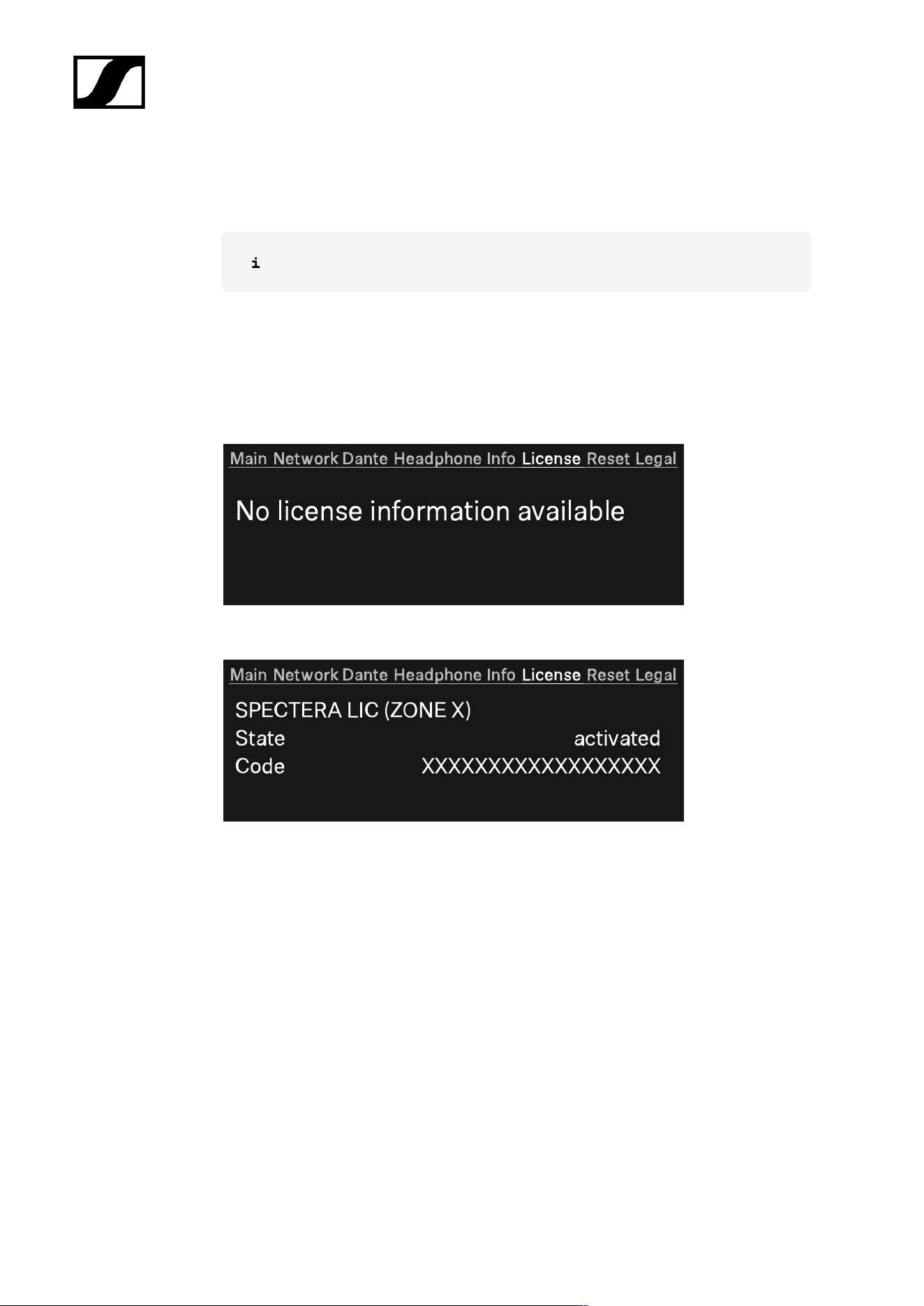
License
In this menu item, information about the license can be shown here.
A license has to be activated, otherwise you cannot use the Base Station.
You can activate a license via LinkDesk or Spectera WebUI.
Only one license per Base Station is possible.
The license specifies the country-specific frequency ranges and the RF power.
No license is activated:
A license is activated
Name of the purchased license:
• Spectera LIC (ZONE 01)
• ...
• Spectera LIC (ZONE XX)
State: Status of the license.
• activated
• unknown
Code:
• The activated license number has 18 digits.
• n/a
65
| 4 - User manual
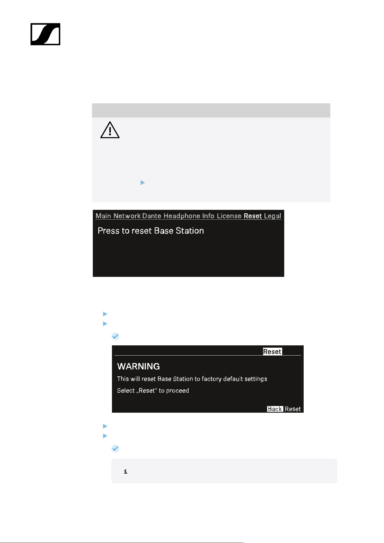
Reset
In this menu item, you can reset the Base Station to its factory settings.
NOTICE
Data loss during the factory reset
All audio devices will be unpaired and all audio routes will be deleted.
All settings (including the device password) are reset to the default
values. The license remains activated.
After the reset, the device is restarted automatically.
Do not reset the Base Station during an active live audio
transmission.
To reset the Base Station to its factory default settings using the device:
On the Base Station, rotate the jog-dial and navigate to the menu Reset.
Press the jog-dial to enter the menu.
A warning will appear.
Rotate the jog-dial to Reset.
Press the jog-dial again.
The Base Station will be set back to factory settings and reboot.
After rebooting, check the IP address as it may have changed.
66

| 4 - User manual
The Base Station has been reset to its factory default settings.
67
| 4 - User manual
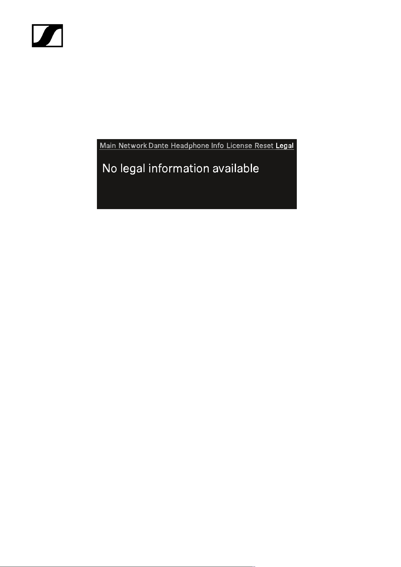
Legal
In this menu item, legal information can be shown.
Legal information about the Base Station and connected antennas are displayed depending
on the activated license.
If no label are available, the display shows:
68
| 4 - User manual
Updating the Base Station
You can update the firmware of the Base Station via LinkDesk or Spectera WebUI.
All Spectera devices must use the same firmware. The Base Station determines the firmware
version.
Please note that firmware versions are not backward compatible.
NOTICE
Data loss during firmware update
The audio transmission is interrupted during the firmware update of the
Base Station, the antenna or the mobile device.
After the firmware update, the device is restarted automatically.
Do not update the firmware during an active live audio
transmission.
To update the firmware:
If you want to update the Base Station via LinkDesk, follow the steps described here:
Updating the firmware (Base Station).
The LED is flashing green and red during the update.
If you want to update the Base Station via Spectera WebUI, follow the steps described
here: Updating the firmware (Base Station).
The LED is flashing green and red during the update.
When the update is installed, the Base Station restarts.
The update will be installed on the connected antennas automatically.
The firmware has been updated.
The new firmware is distributed to the other devices via the Base Station.
69
| 4 - User manual
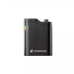
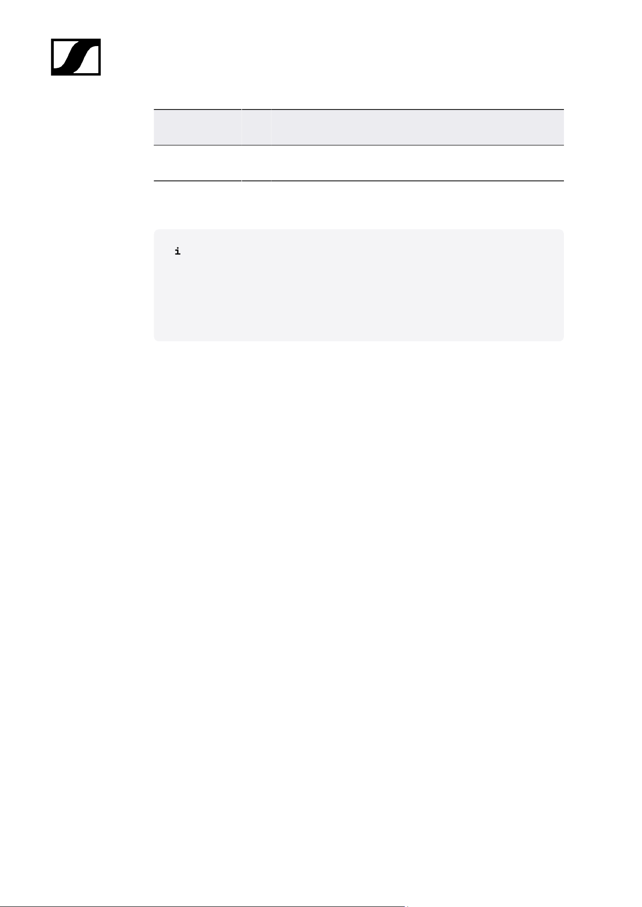
SEK
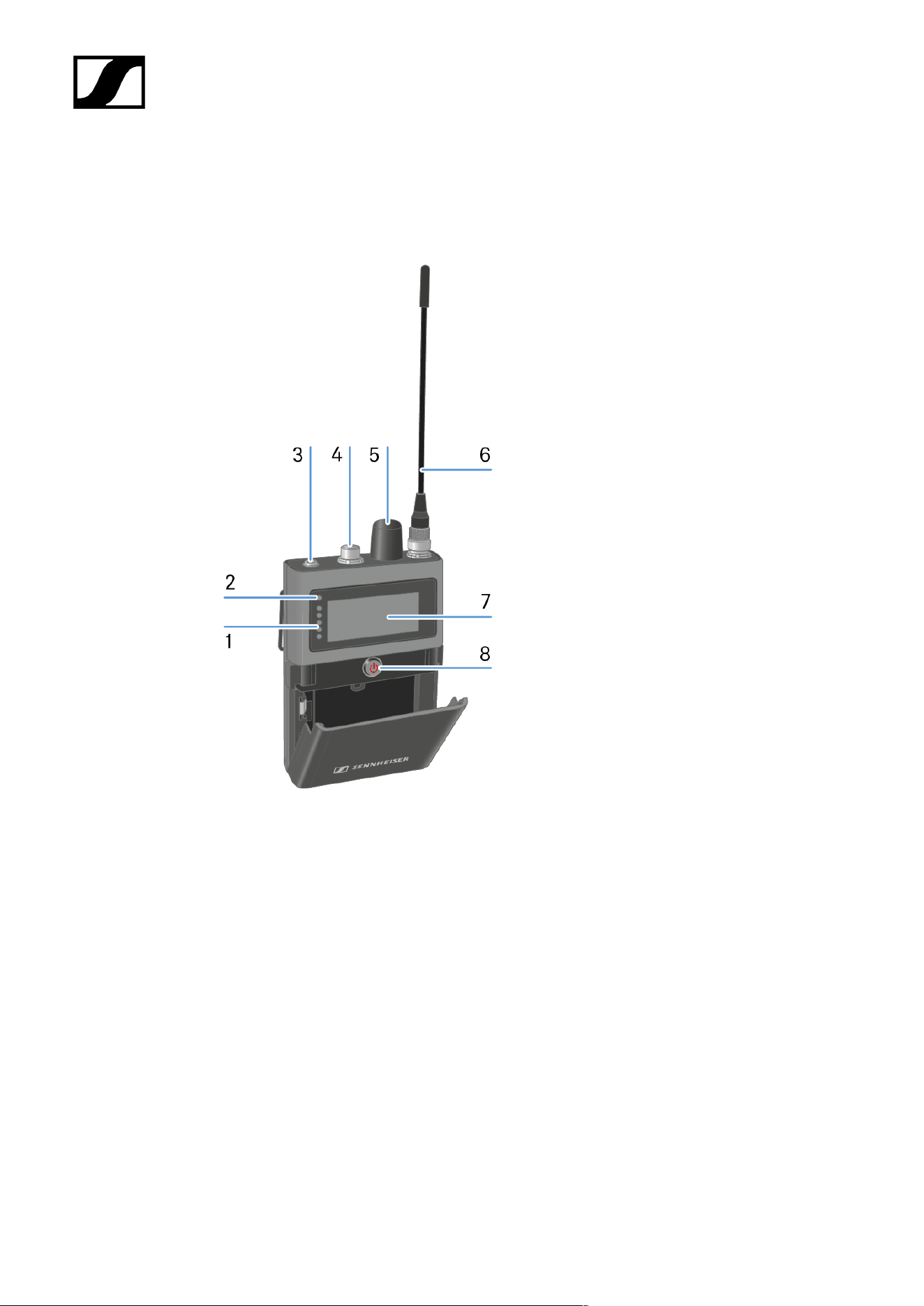
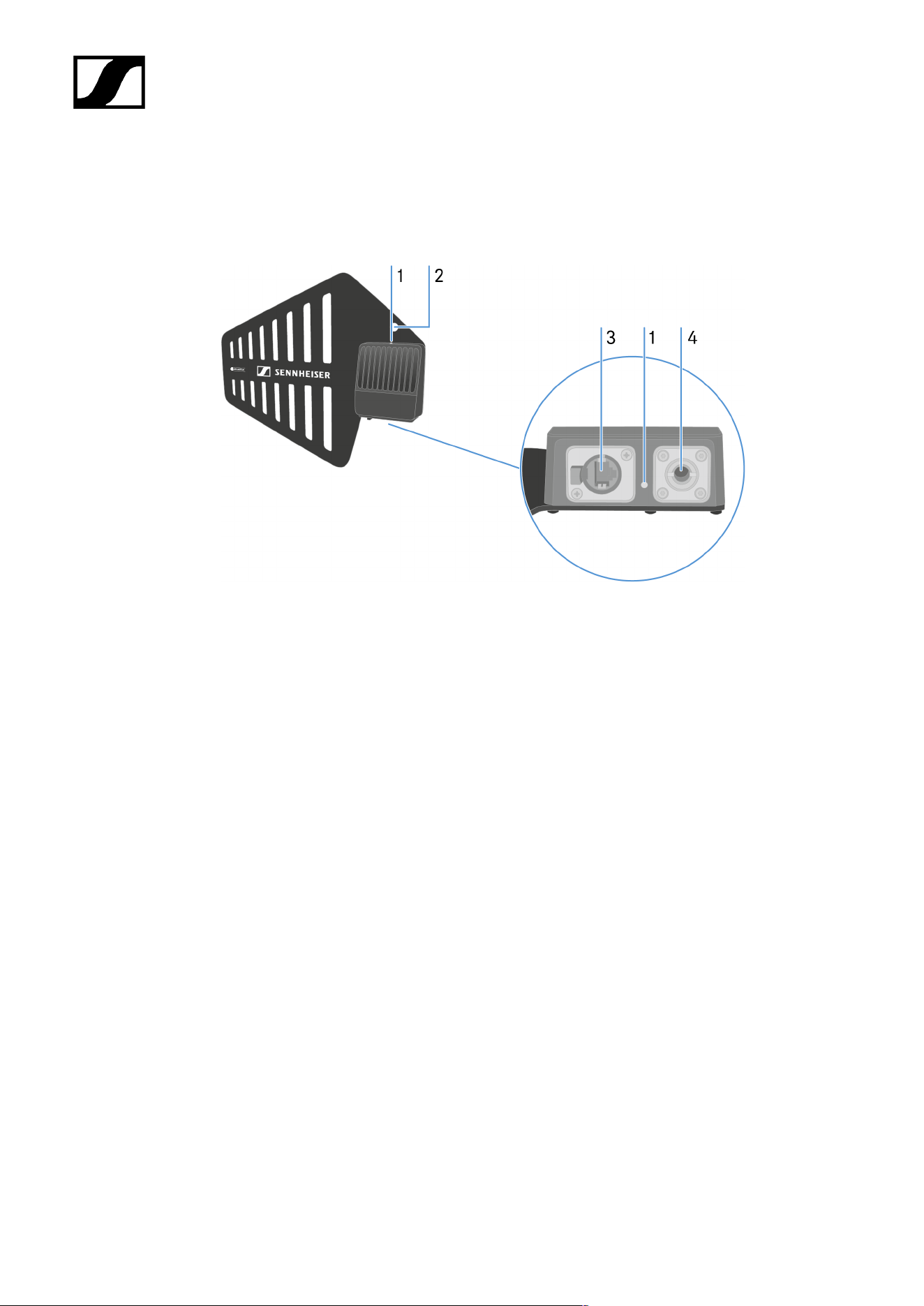
Product overview
1 LEDs
see Meaning of the LEDs
2 Status LED
see Meaning of the LEDs
3 Phones 3.5 mm jack
see Connecting earphones
4 Microphone / Instrument input
see Connecting a microphone / instrument
5 Rotary encoder
with push function
see Information on the display
6 Antenna
see Mounting the antenna
70

| 4 - User manual
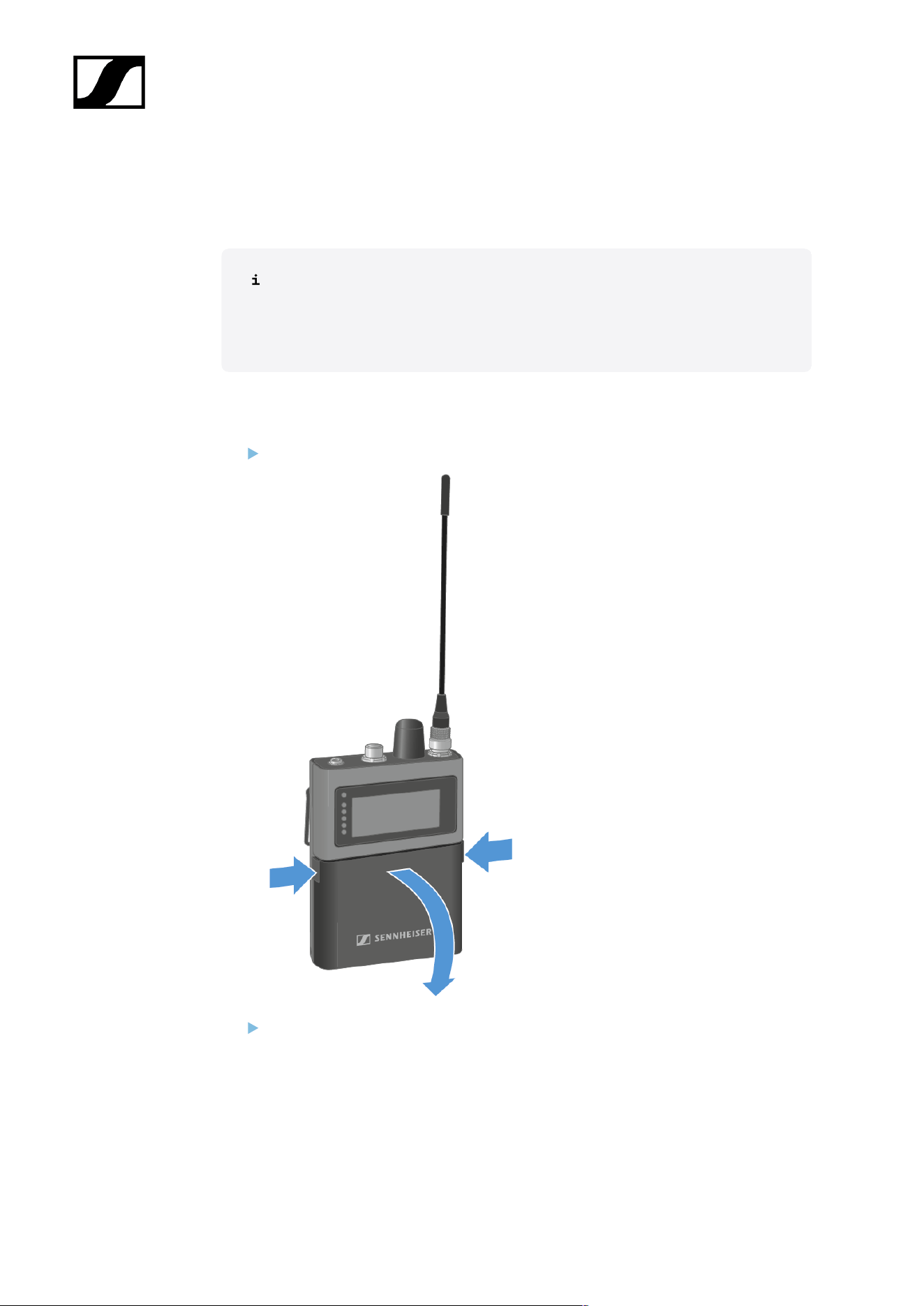
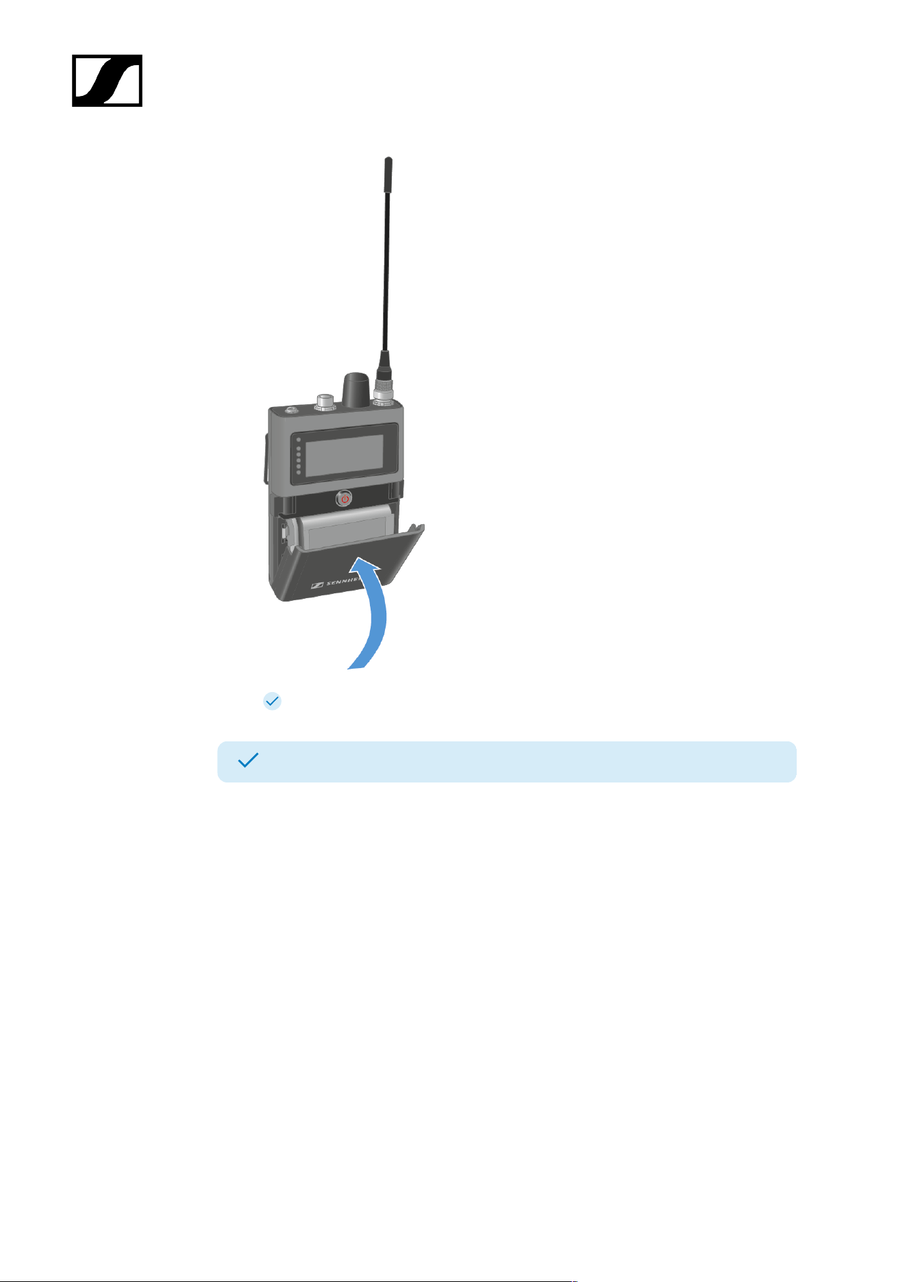
Inserting and removing the rechargeable battery
The SEK operates only with the recharable battery BA 70 (seperate accessory).
The BA 70 can be charged in the L 70 USB, the L 6000 with LM 6070 or with the
SEK in the CHG 70N-C. See Charging the rechargeable battery, Charging the
rechargeable batteries in the L 6000 charger and Charging the rechargeable
battery.
To insert the recharable battery into the SEK:
Press the two catches and open the battery compartment cover.
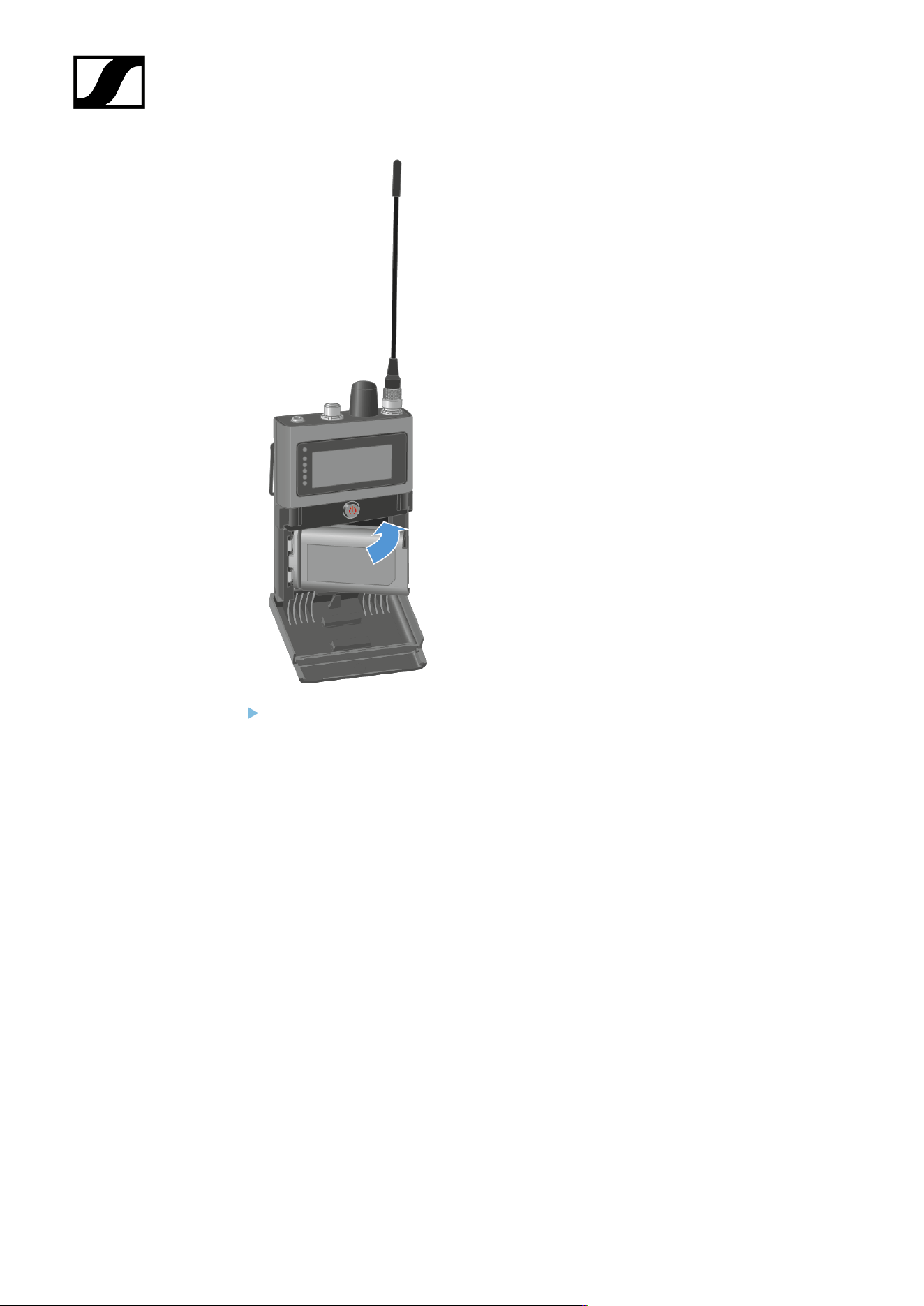
Insert the BA 70 rechargeable battery in the battery compartment.
72
| 4 - User manual
Close the battery compartment.
73
| 4 - User manual
The cover locks into place with an audible click.
The battery has been inserted.
74
| 4 - User manual
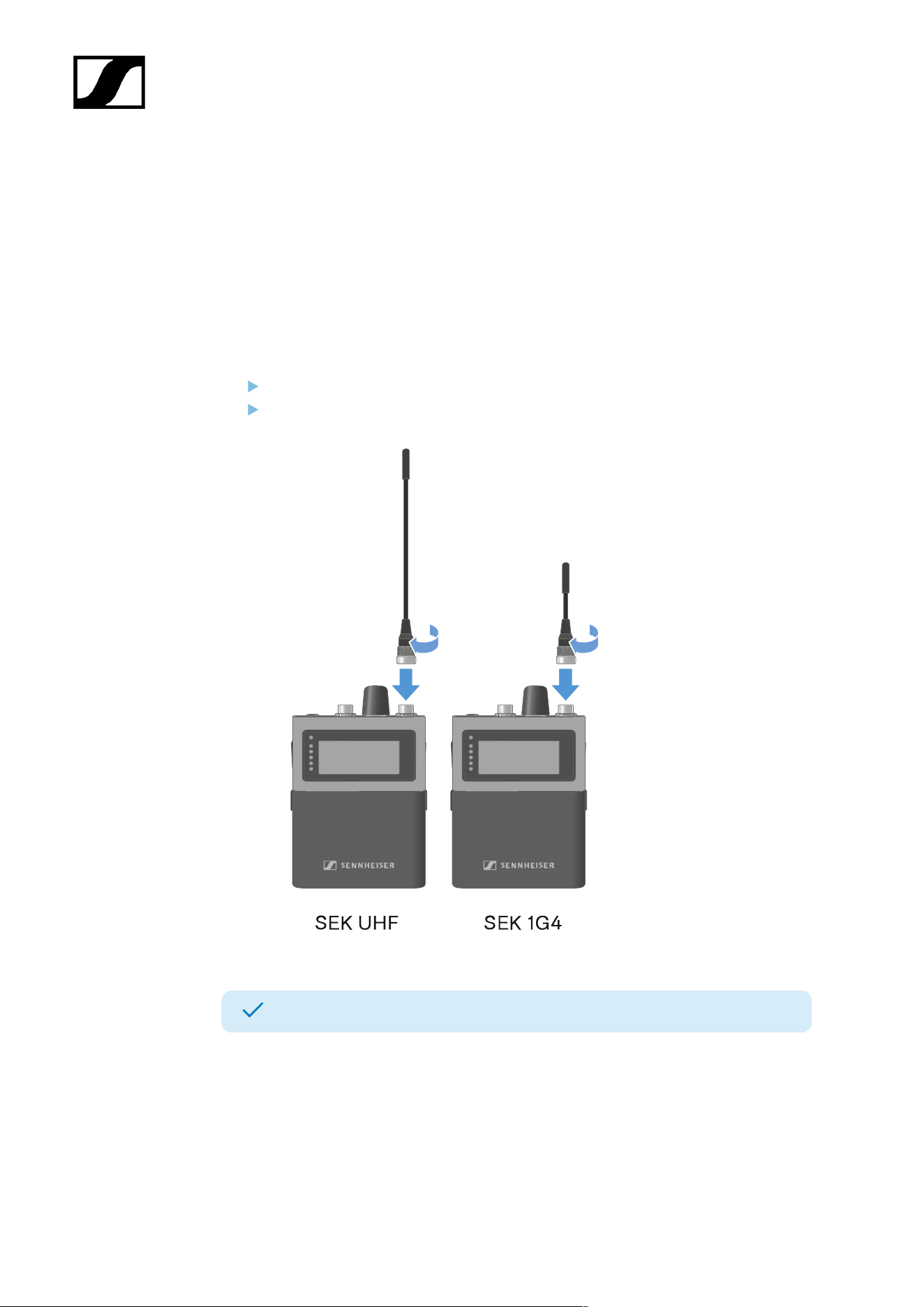
Mounting the antenna
Two antennas are available, one for each frequency range.
For more information see Spectera SEK Antenna.
The antenna is screwed on when it is delivered.
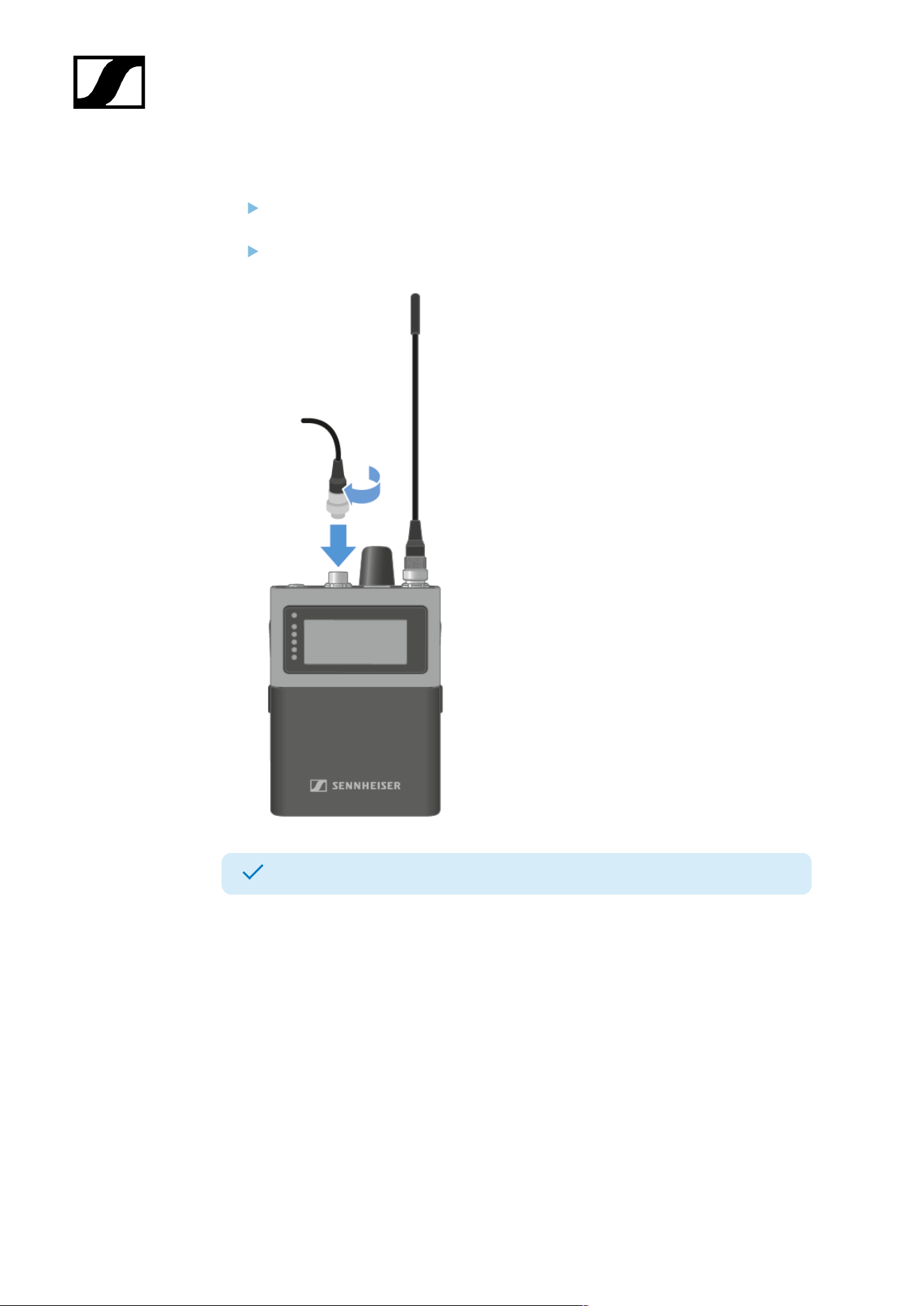
To mount the antenna to the SEK:
Connect the antenna to the SEK antenna socket.
Tightly screw the antenna coupling ring onto the SEK antenna socket.
The antenna has been mounted.
75
| 4 - User manual
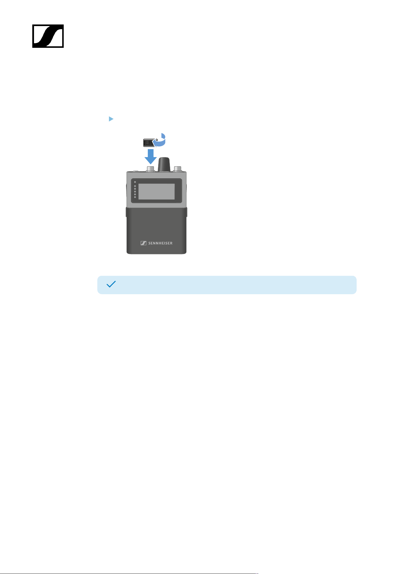
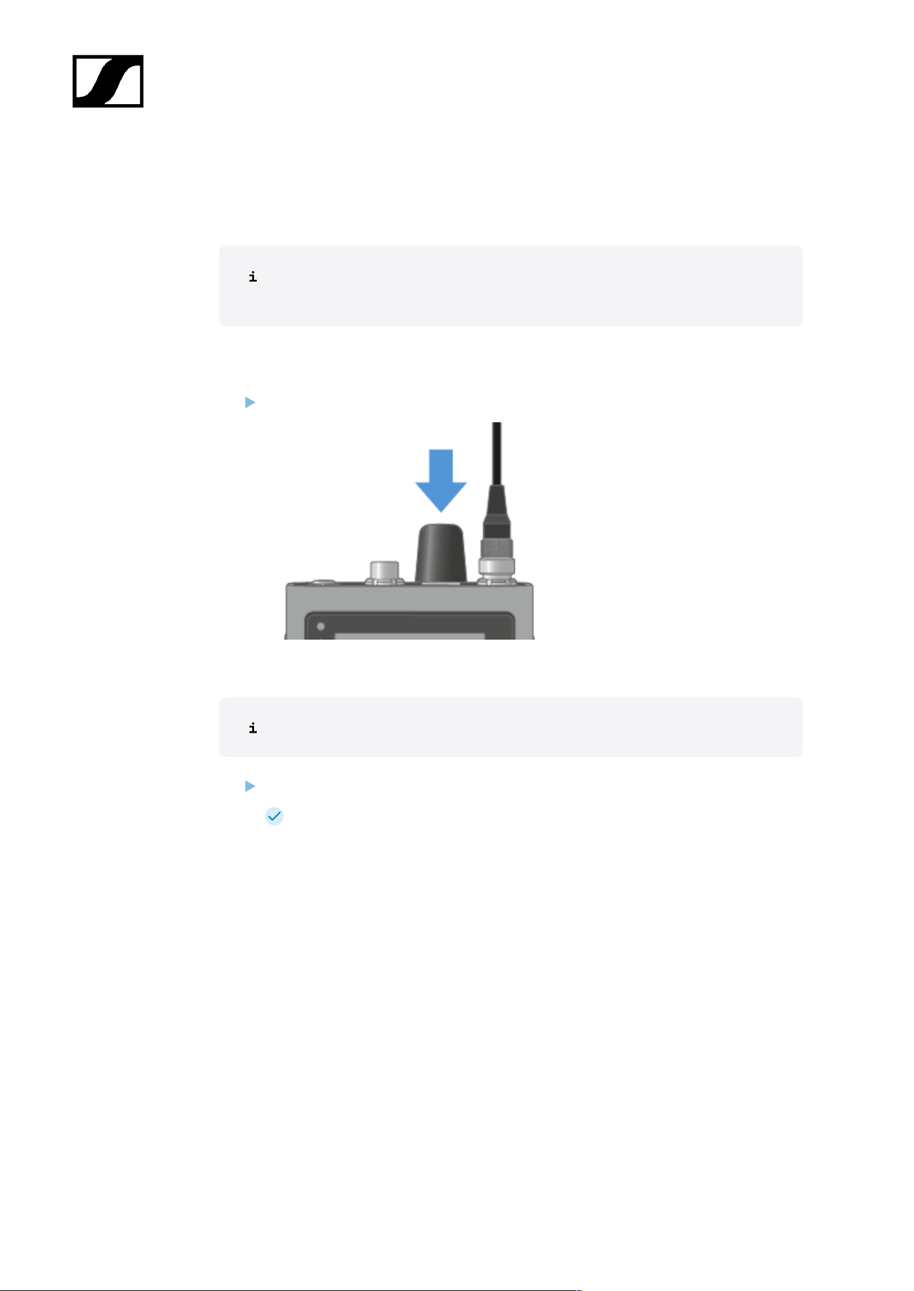
Using the protection cap
The cap protects the microphone / instrument input, when not in use.
To screw the cap on the SEK:
Screw the cap on the microphone / instrument input socket.
The cap has been attached.
76
| 4 - User manual
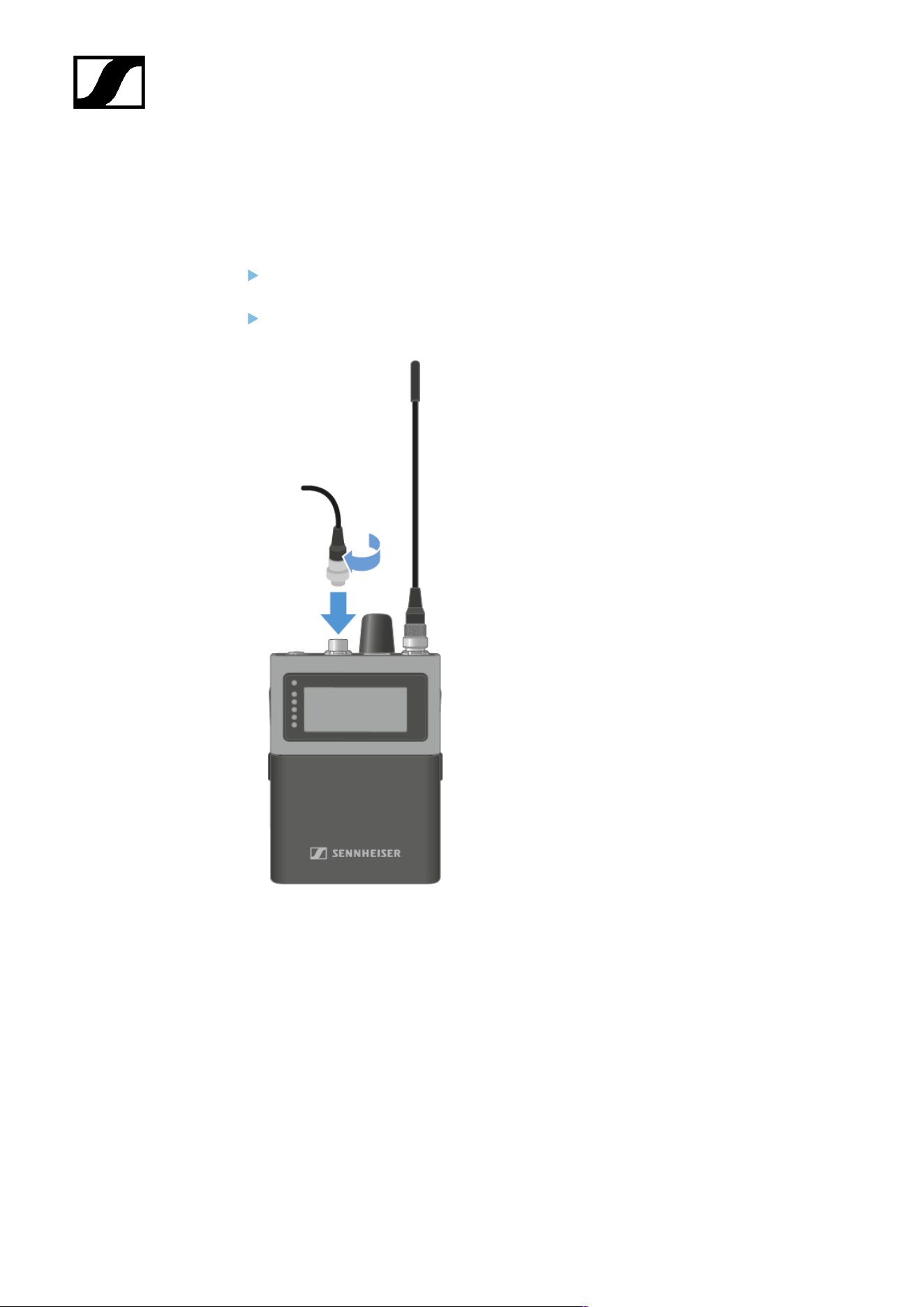
Connecting a microphone / instrument
You can connect a microphone or instrument to the SEK.
To connect a microphone to the SEK:
Use a 3-pin audio connector to connect the microphone cable to the SEK
microphone / instrument input socket.
Screw the plug’s coupling ring onto the microphone / instrument input thread of the
SEK.
77
| 4 - User manual
To connect a instrument to the SEK:
Use a 3-pin audio connector to connect the instrument cable to the SEK microphone /
instrument input socket.
Screw the plug’s coupling ring onto the microphone / instrument input thread of the
SEK.
A microphone or instrument has been connected.
78

| 4 - User manual
Connecting earphones
You have to set up an audio link in LinkDesk or Spectera WebUI.
CAUTION
Danger due to high volume levels
Volume levels that are too high may damage your hearing.
Turn down the volume of the headphone output before you put on
the headphone.
The SEK checks the headphone's impedance when a headphone is plugged in at switching
on, or each time a headphone is newly plugged in.
To connect earphones to the SEK:
Turn down the volume.
The volume can be altered between -100 dB to +27.5 dB in steps of 0.5 dB.
Insert the cable’s 3.5 mm jack plug into the phones socket on the SEK.
79

| 4 - User manual
The earphones have been connected.
80
| 4 - User manual
Changing the belt clip
You can change the belt clip on the SEK or flip it over depending on how you want to wear
it.
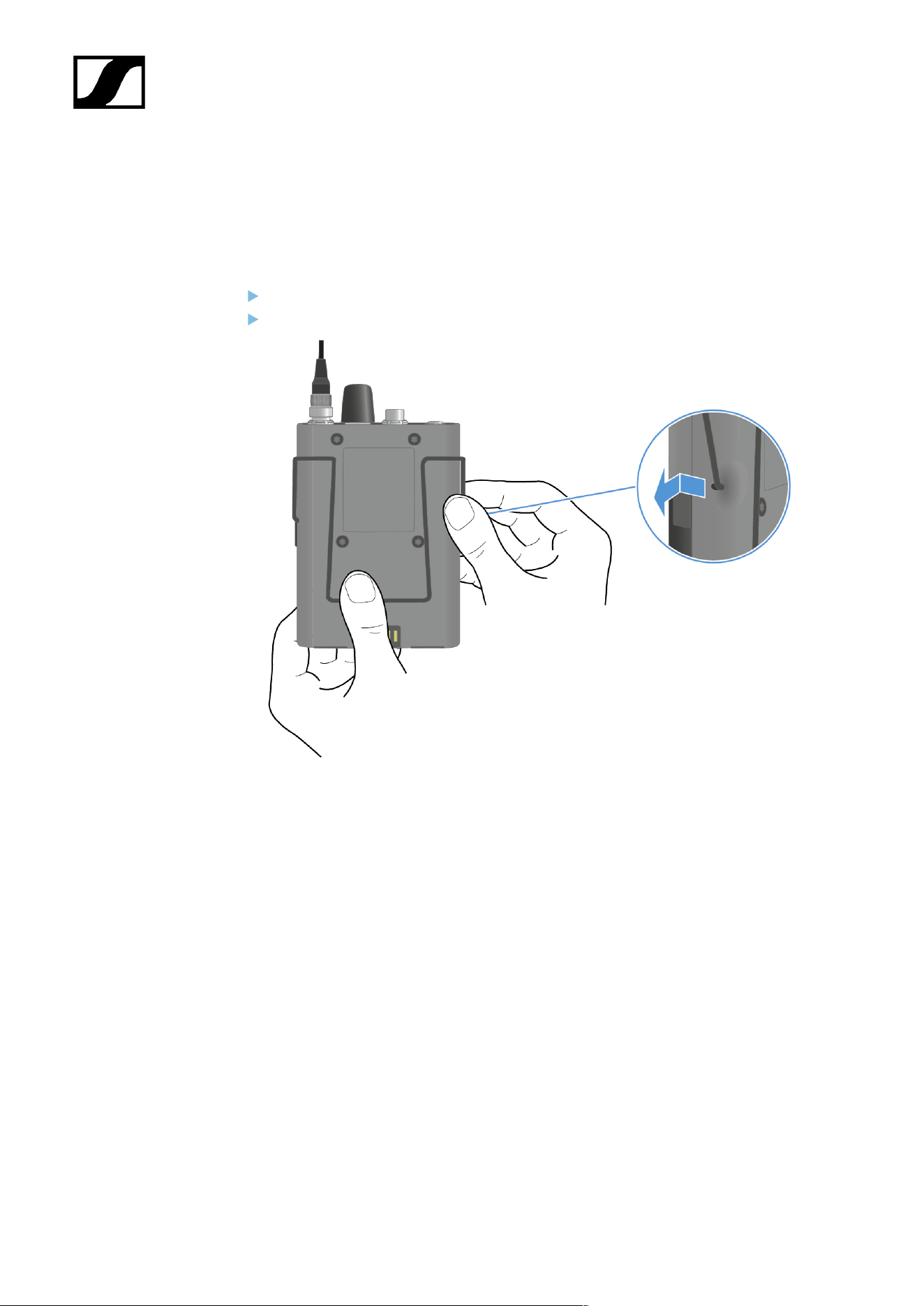
To remove the belt clip:
Hold down the belt clip with the thump to the housing.
Use the other hand to carefully pull back and then out one side of the belt clip.
81
| 4 - User manual
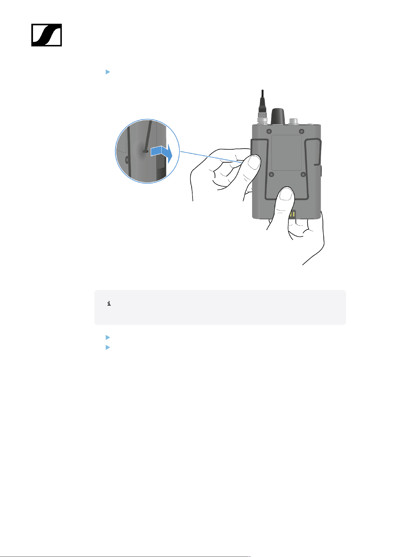
While still holding the belt clip down, carefully pull back and then out the other side of
the belt clip.
To insert the belt clip:
Always insert one side before the other, not at the same time, as otherwise the
belt clip could bend.
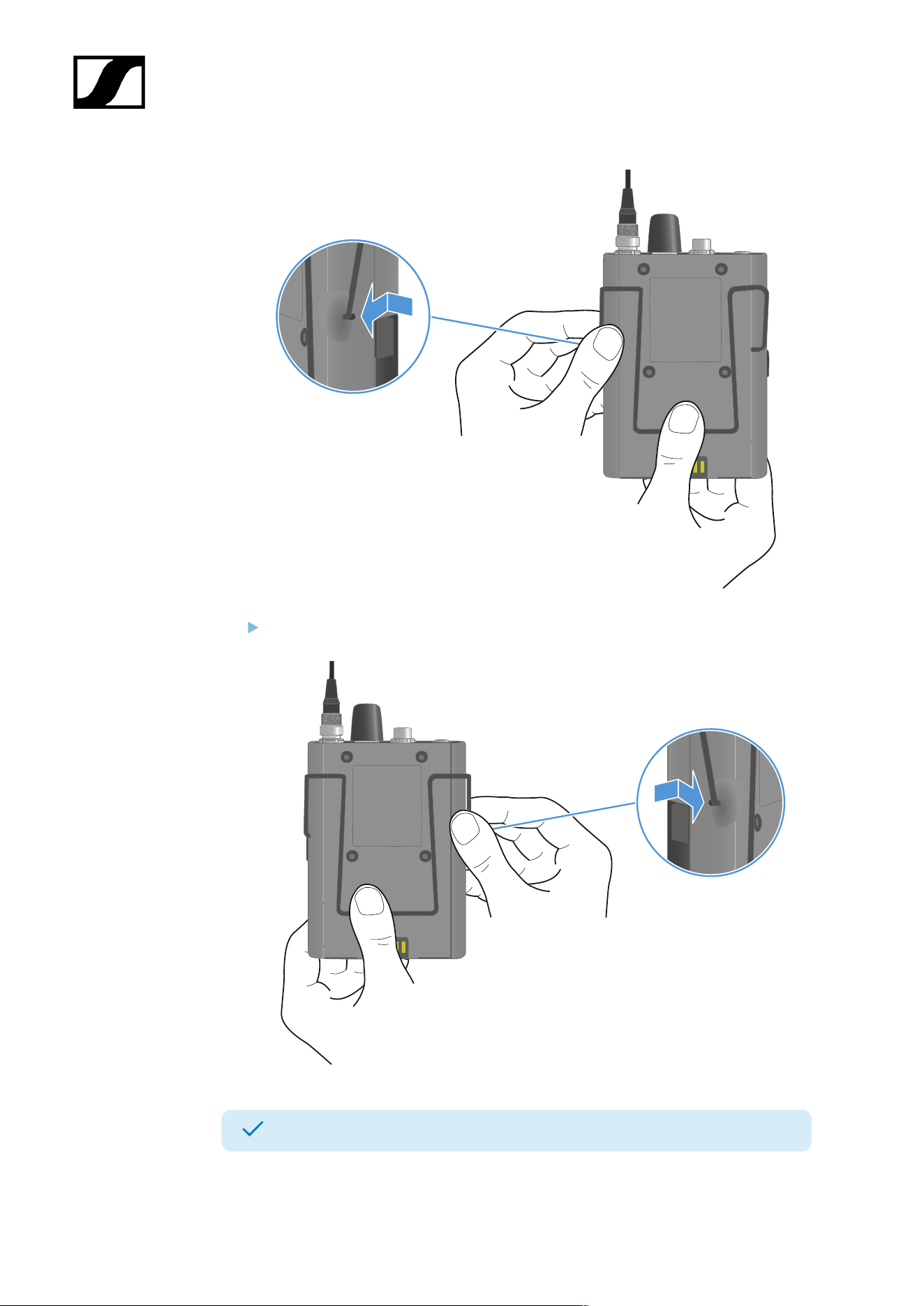
Hold down the belt clip with the thump to the housing.
Insert one side of the belt clip first.
82
| 4 - User manual
Then insert the second side of the belt clip.
The beld clip has been removed and inserted.
83
| 4 - User manual
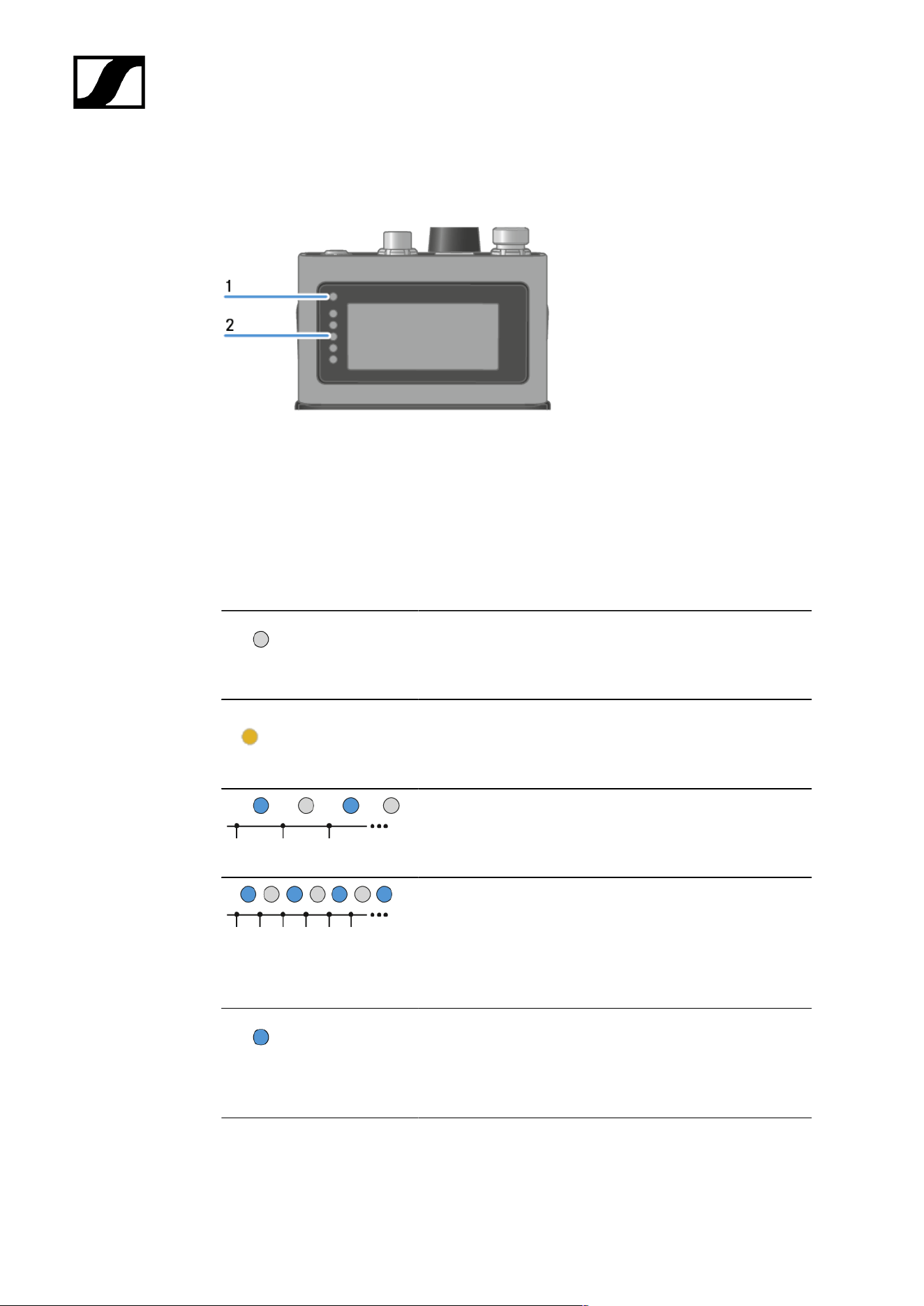
Meaning of the LEDs
The Status LED and LEDs can indicate the following information.
1 Status LED
2 LEDs
Status LED
The Status LED provides information about the status between the SEK and Base Station, as
well as status information for the SEK.
The LED is off:
• SEK is switched off
The LED is orange:
• SEK is starting
The LED is flashing blue:
• Searching for a new Base Station to pair
The LED is flashing blue quickly:
• Pairing to new Base Station is in progress
• SEK turns off after five minutes, when no Base
Station was found
The LED is blue:
• Connected to new Base Station, waiting for
confirmation
84
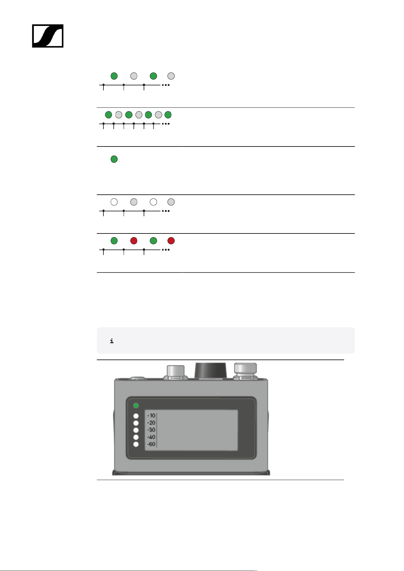
| 4 - User manual
The LED is flashing green:
• SEK is searching for previously paired Base Station
The LED is flashing green quickly:
• SEK is connecting to previous paired Base Station
The LED is green:
• SEK is on
• SEK is connected to the Base Station
The LED is flashing white
• Identify of SEK is in progress
The LED is flashing green and red:
• Firmware update is in progress
LEDs
The LEDs provide information about the mic line input level, if a microphone or instrument is
connected to the SEK.
You have to set up an audio link in LinkDesk or Spectera WebUI.
85
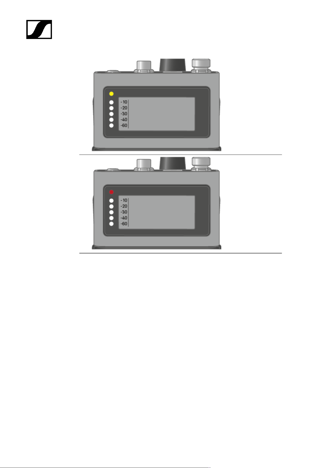
| 4 - User manual
above -5 dBFS RMS
above -1 dBFS
PEAK
86
| 4 - User manual
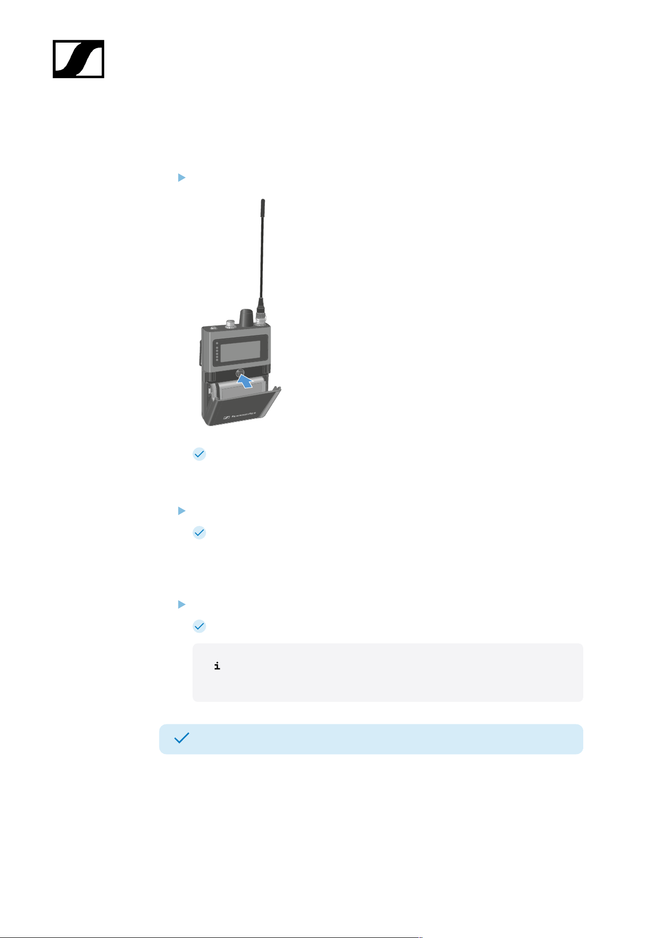
Switching the SEK on and off
To switch the SEK on:
Short-press the ON/OFF button.
The SEK is starting. The status LED is orange.
To put the SEK in pairing mode:
When the SEK is off, long press the ON/OFF button.
The SEK is searching for a new Base Station to pair. The status LED is flashing
blue.
To switch the SEK off:
Short-press the ON/OFF button.
The status LED goes off.
The display will stay on when the device is switched off or the battery
has been removed.
The SEK has been switched on/off.
When the SEK is unpaired via the software (LinkDesk or Spectera WebUI), the SEK will
automatically switch into pairing mode. The status LED is flashing blue.
87
| 4 - User manual
Information on the display
You can view the following information on the SEKs display.
The display will stay on when the device is switched off or the battery has been
removed.
The order of the displayed information changes depending on the setting.
Press the rotary encoder to navigate through the menu.
To turn on the backlight:
No microphone or headphone is connected.
Press the rotary encoder.
The backlight is on for five seconds.
88
| 4 - User manual
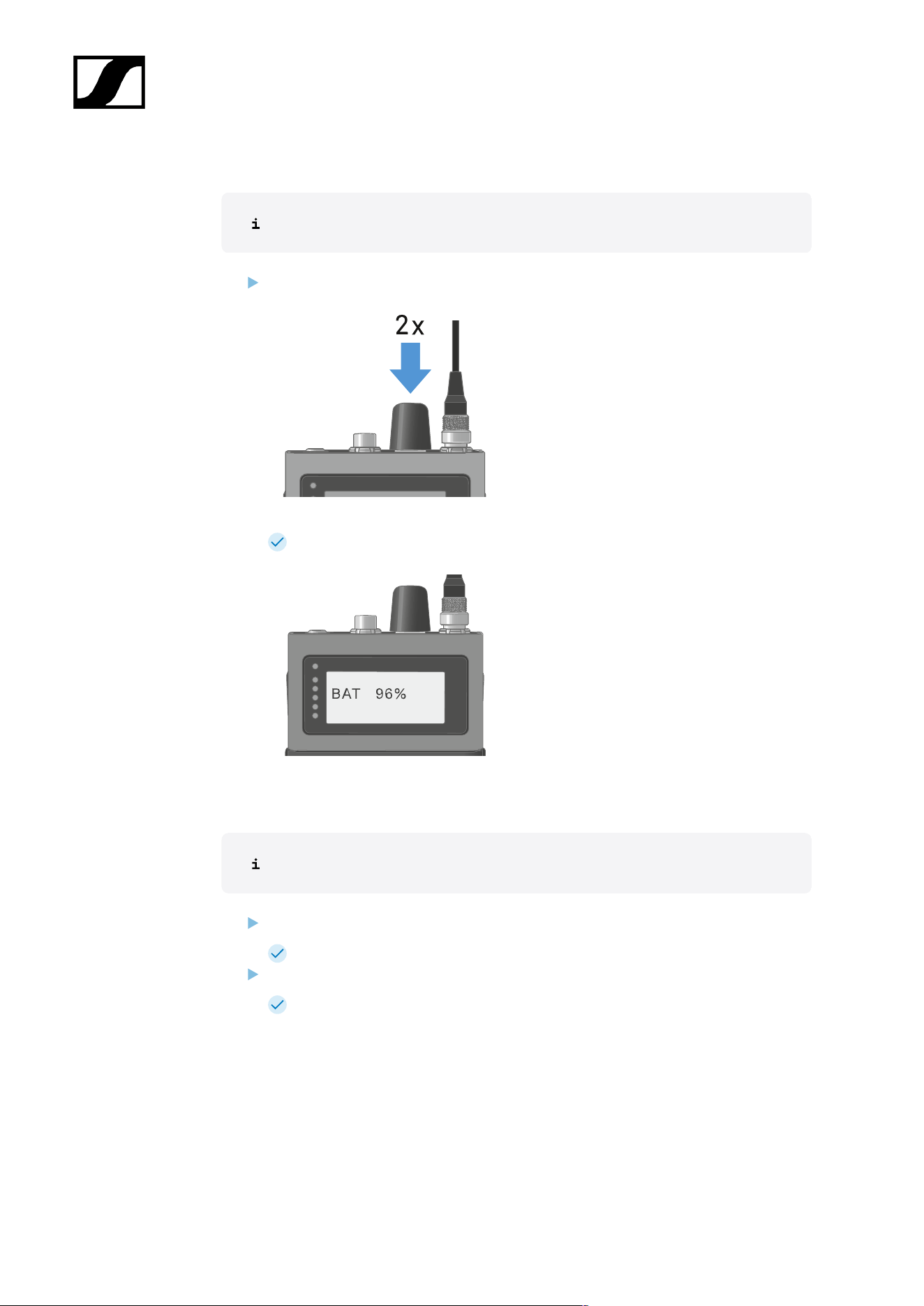
To check the battery status:
No audio link is set.
Press the rotary encoder for two times.
The battery status displays for five seconds.
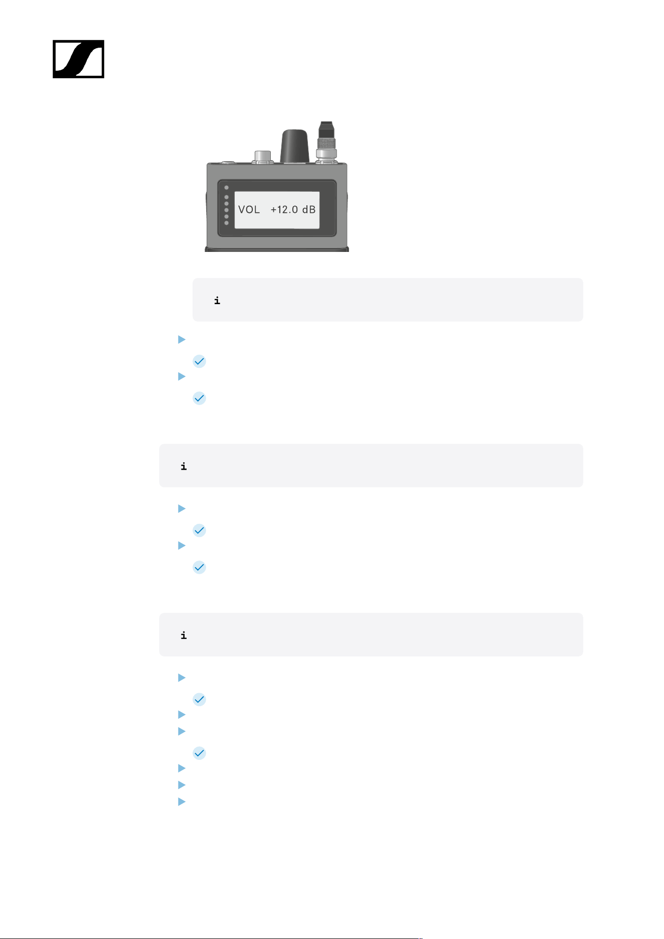
To display the headphone volume:
Only available if in-ear audio link mode is activated.
Press the rotary encoder.
The backlight is on for five seconds.
Press the rotary encoder again within 5 seconds after the first press.
The headphone volume displays for five seconds.
89
| 4 - User manual
The volume can be altered between -100 dB to +27.5 dB in steps of 0.5 dB.
Turn the rotary encoder slowly to change the volume.
The volume changes by 0.5 dB per click.
Turn the rotary encoder quick to change the volume.
The volume changes dynamically in larger increments.
To display the mic/line level:
Only available if mic audio link is activated.
Press the rotary encoder.
The backlight is on for five seconds.
Press the rotary encoder again within 5 seconds after the first press.
The mic/line level is displayed. The five LEDs show the input level.
To display the E-label:
The SEK is paired to the Base Station and the activated license uses E-labels.
Press the rotary encoder.
The backlight is on for five seconds.
Press the rotary encoder till the end of the menu.
Press the rotary encoder long for E-label screen.
The first page of the E-label displays.
Press the rotary encoder again to display subsequent E-labels.
Press the rotary encoder long to return to the information screen.
Press the rotary encoder for two seconds to leave the E-label menu.
90

| 4 - User manual
Pairing the SEK to the Base Station
Mobile devices can only be paired and operated with one Base Station at a time.
You can pair up to 128 mobile devices to a Base Station within one RF channel.
Please make sure that on the Base Station
• a RF channel is configured and
• this RF channel is activated (RF on).
To pair the SEK to a Base Station:
Put the Base Station into Pairing Mode using LinkDesk or Spectera WebUI.
The LED flashes blue.
Pairing Mode is activated for five minutes. The audio signal is not
interrupted.
While the SEK is off, long-press the ON/OFF button until the Status LED is blue.
The status LED is flashing blue while searching for a new Base Station.
When the SEK found the Base Station, the status LED is flashing blue quickly and
then is blue.
The SEK appears in the software.
Confirm the pairing in the software, see LinkDesk: Adding mobile devices and
Spectera WebUI: Pairing/unpairing mobile devices.
The status LED of the SEK is flashing green quickly while connecting. When
connecting is completed, the status LED is green.
To unpair the SEK from a Base Station:
The SEK can only be unpaired in LinkDesk or Spectera WebUI.
• LinkDesk: Pairing/unpairing mobile devices
• Spectera WebUI: Pairing/unpairing mobile devices
The SEK will automatically switch to pairing mode. The status LED is flashing
blue.
The SEK has been paired to a Base Station.
91
| 4 - User manual
Updating the SEK
You can update the firmware of the SEK via LinkDesk or Spectera WebUI.
All Spectera devices must use the same firmware version. The Base Station determines the
firmware version.
NOTICE
Data loss during firmware update
The audio transmission is interrupted during the firmware update of the
Base Station, the antenna or the mobile device.
After the firmware update, the device is restarted automatically.
Do not update the firmware during an active live audio
transmission.
To update the firmware:
If you want to update the SEK via LinkDesk: Updating the firmware (mobile devices).
The Status LED is flashing green and red during the update.
If you want to update the SEK via Spectera WebUI: Updating the firmware (mobile
devices).
The Status LED is flashing green and red during the update.
The firmware has been updated.
92
| 4 - User manual
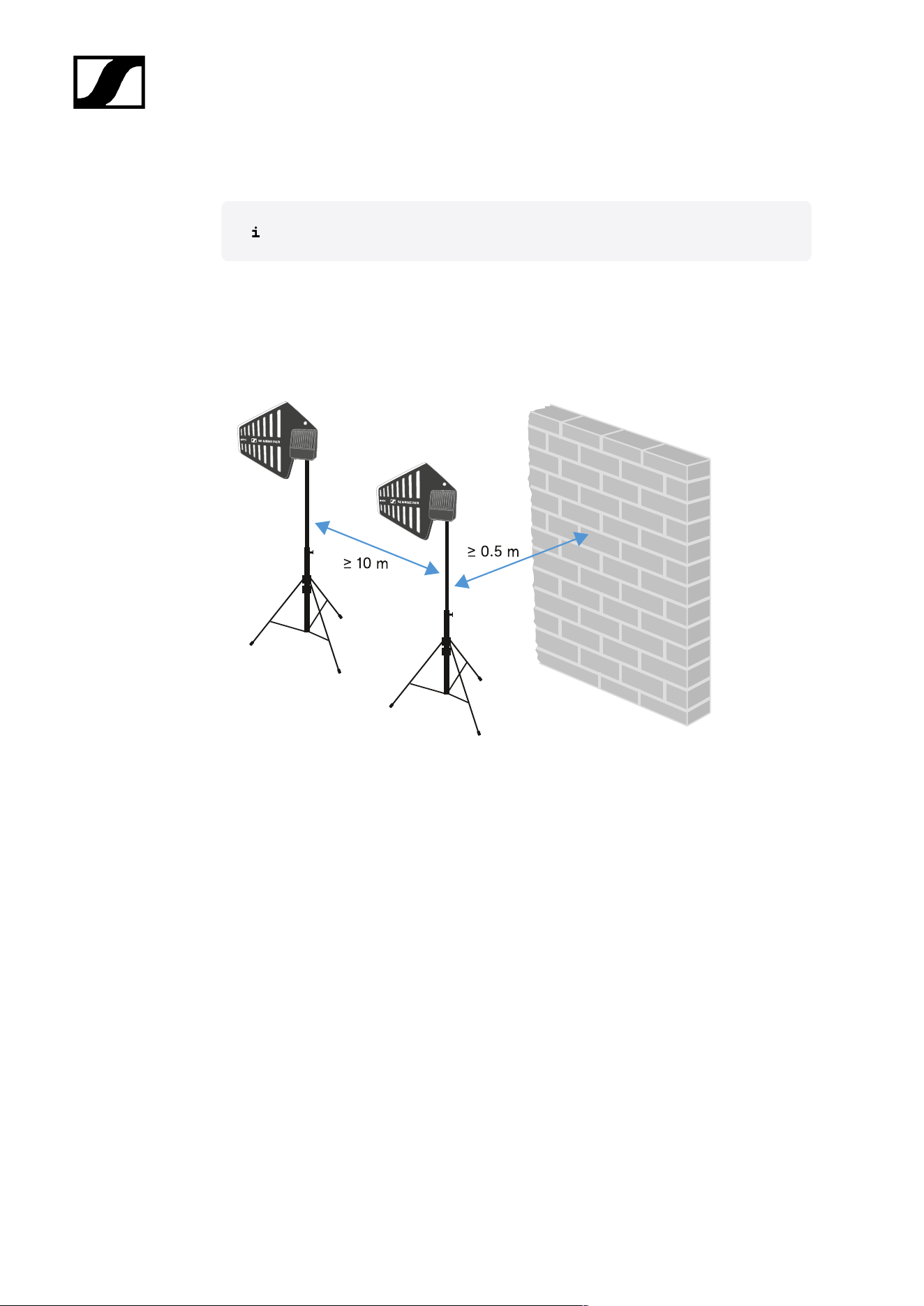
Information on antenna setup
Handle with care: The antenna contains electrical components.
Setup with other antennas
• Keep a distance more than 10 m (393.7") between the antenna and another antenna.
• Keep a distance more than 0.5 m (19.69") between the antenna and a wall.
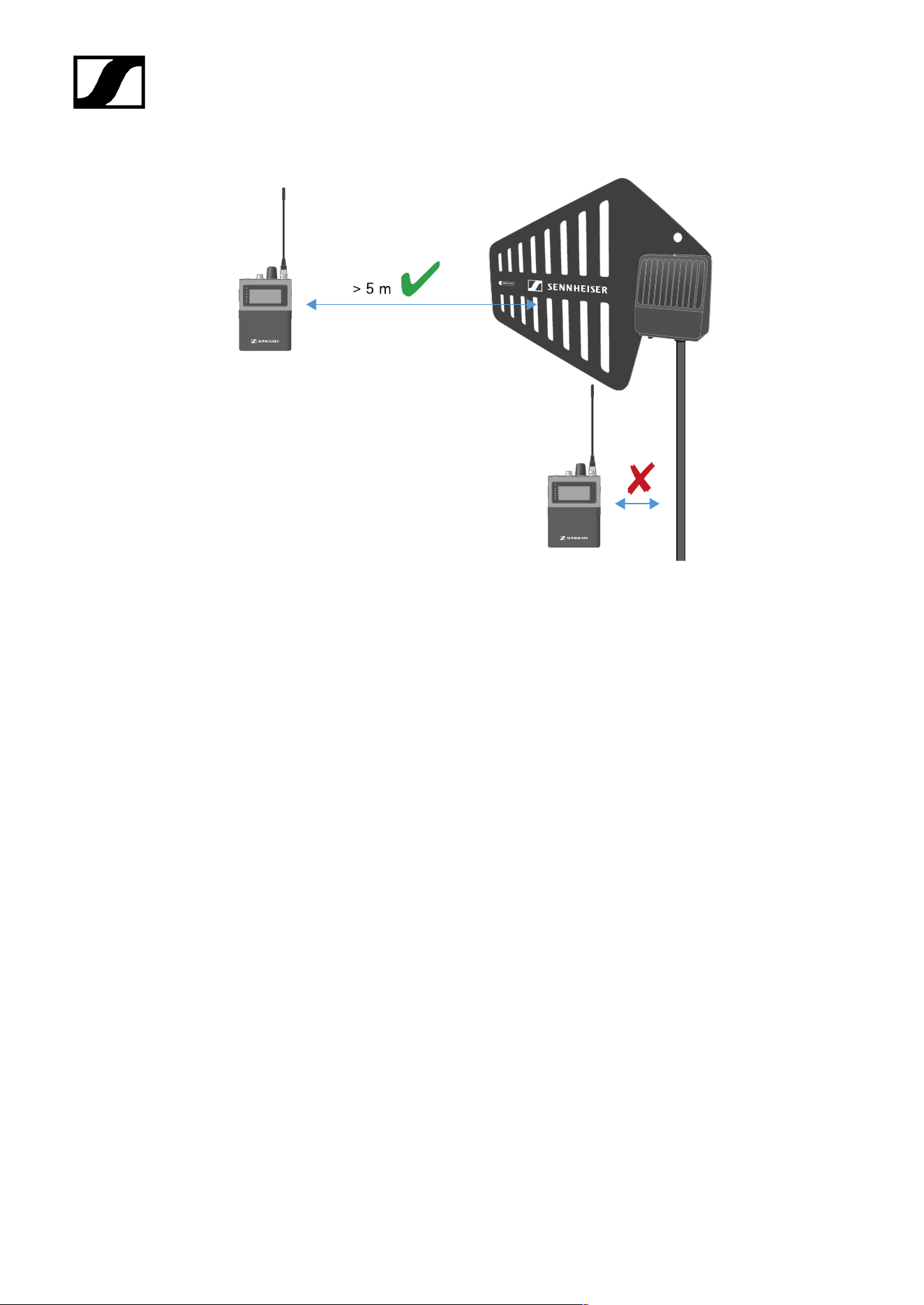
Setup with a mobile device
• Keep a distance more than 5 m (169.85") between the antenna and the mobile device.
94
| 4 - User manual
95
| 4 - User manual
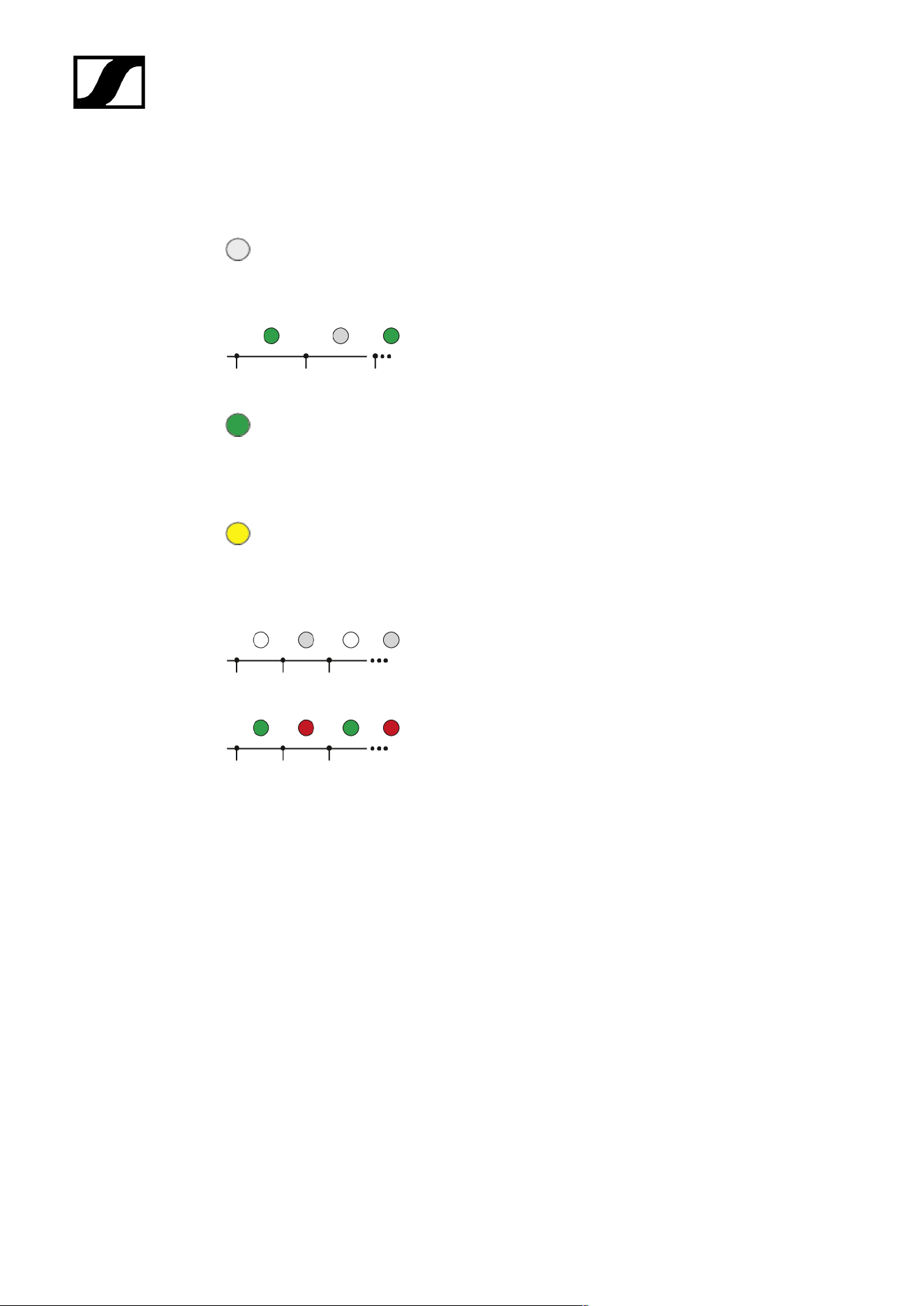
Meaning of the LED
The LED on top and below indicates the same information.
The LED is off:
• The antenna is not connected to the Base Station.
The LED is flashing green:
• The antenna is connecting to the Base Station.
The LED is green:
• The antenna is connected to the Base Station and one
or both RF channels are active.
The LED is yellow:
• The antenna is connected to the Base Station and one
or both RF channels are muted.
The LED is flashing white:
• The connected antenna is identified.
The LED is flashing green and red:
• Firmware update is in progress.
96
| 4 - User manual
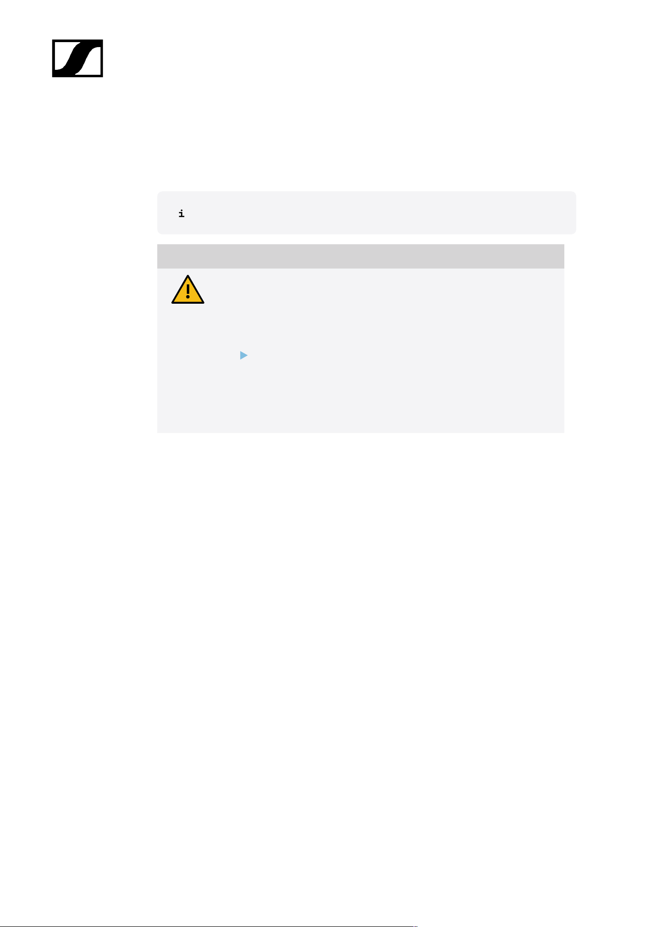
Placing on a stand
The thread is suitable for mounting on a standard microphone stand with 3/8" or 5/8"
thread.
Handle with care: The antenna contains electrical components.
CAUTION
Personal injury and damage to property if the antennae should
tip or fall over
If you do not secure the antennae against tipping or falling over, they may
cause personal injury and damage to property.
Secure antennae so that they cannot tip and fall over. Use safety
wires for this purpose. The safety wires, rope terminations and
coupling links must comply in their dimensioning and condition
with the regulations and standards of the country in which they
are used!
97
| 4 - User manual
To place the DAD on a stand:
Screw the DAD to the stand.
Make sure to use the correct hole!
The DAD has been placed on a stand.
98
| 4 - User manual
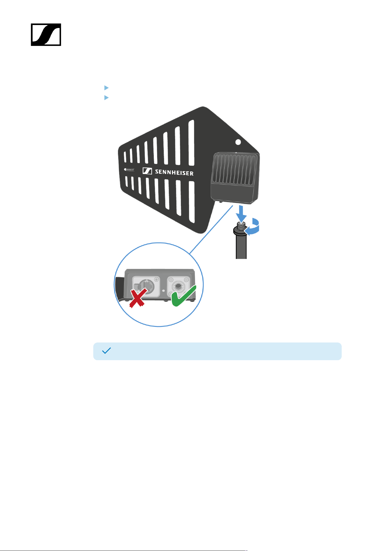
Connecting/disconnecting the antenna
The cable supplies power and exchanges data.
Handle with care: The antenna contains electrical components.
The cable must
• be a CAT5e or higher,
• have ruggedized plugs and
• not extend 100 m (3937").
We recommend using a antenna cable cat 5e (see Accessories for the DAD).
To connect the antenna to the Base Station:
Observe the information: Information on antenna setup.
The antenna must be connected directly to the Base Station, with no
switch in between.
Plug on side of the cable into the antenna.
Make sure to use the correct hole!
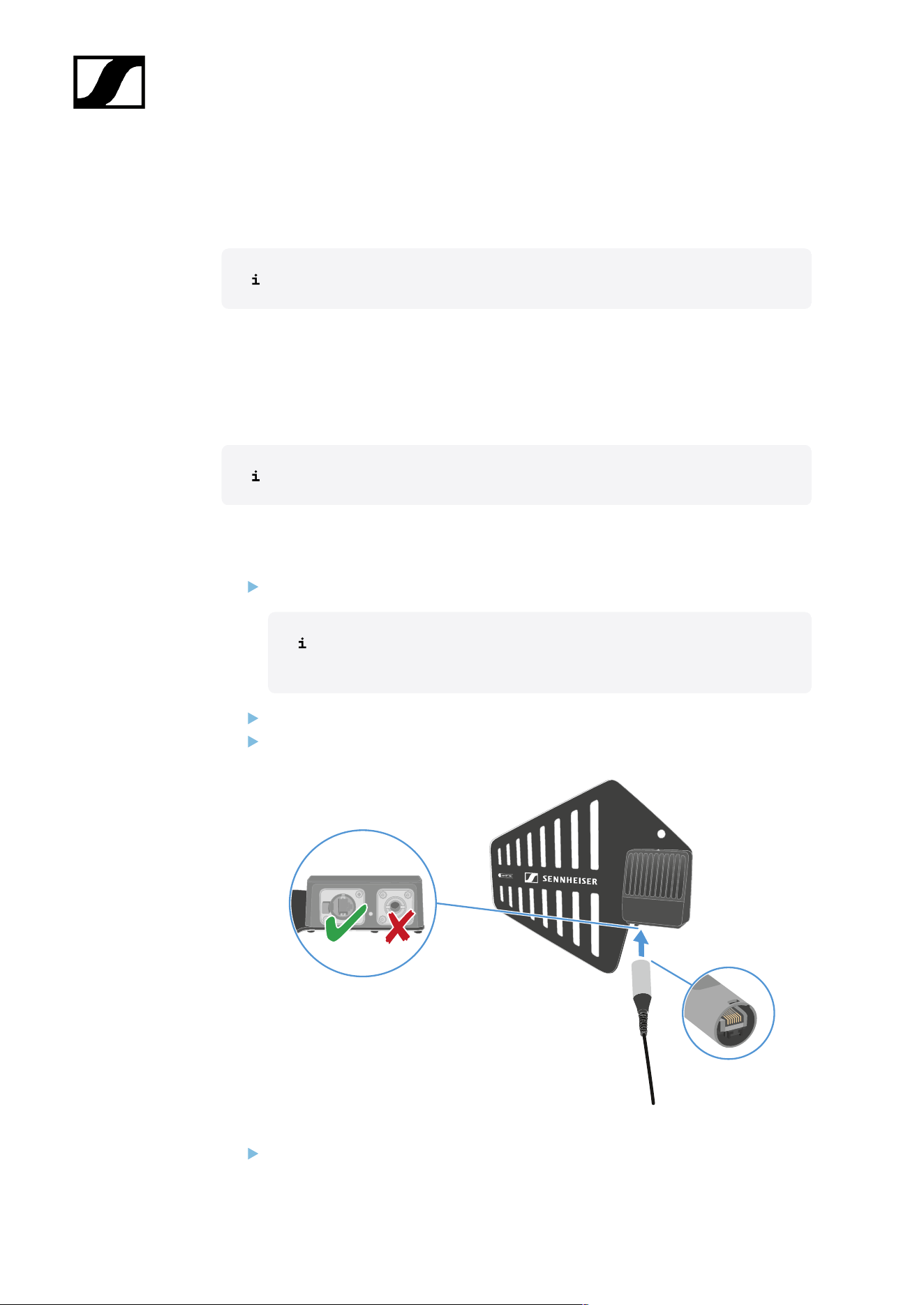
Plug the other side of the cable into one antenna port (A, B, C or D) at the rear site of
the Base Station.
99
| 4 - User manual
The LED flashes green to connect to the Base Station.
The LED is green, when the antenna is connected to the Base Station and and one or
both RF channels are active.
Or the LED is yellow, when the antenna is connected to the Base Station and the radio
signal is muted.
Or the LED is flashing green and red, when the firmware is updating automatically.
If the Base Station is in standby, the DAD is off.
You can connect up to four antennas to one Base Station.
The Base Station has two independend RF channels. Both variants of the antenna
(UHF and 1G4) can be connected to the Base Station at the same time.
To disconnect the antenna from the Base Station:
Hold the push button down.
Unplug the cable from the Base Station.
100
| 4 - User manual
To disconnect the cable from the antenna:
Hold the snap-in nose down.
Unplug the cable from the antenna.
The antenna has been connected/disconnected.
101
| 4 - User manual
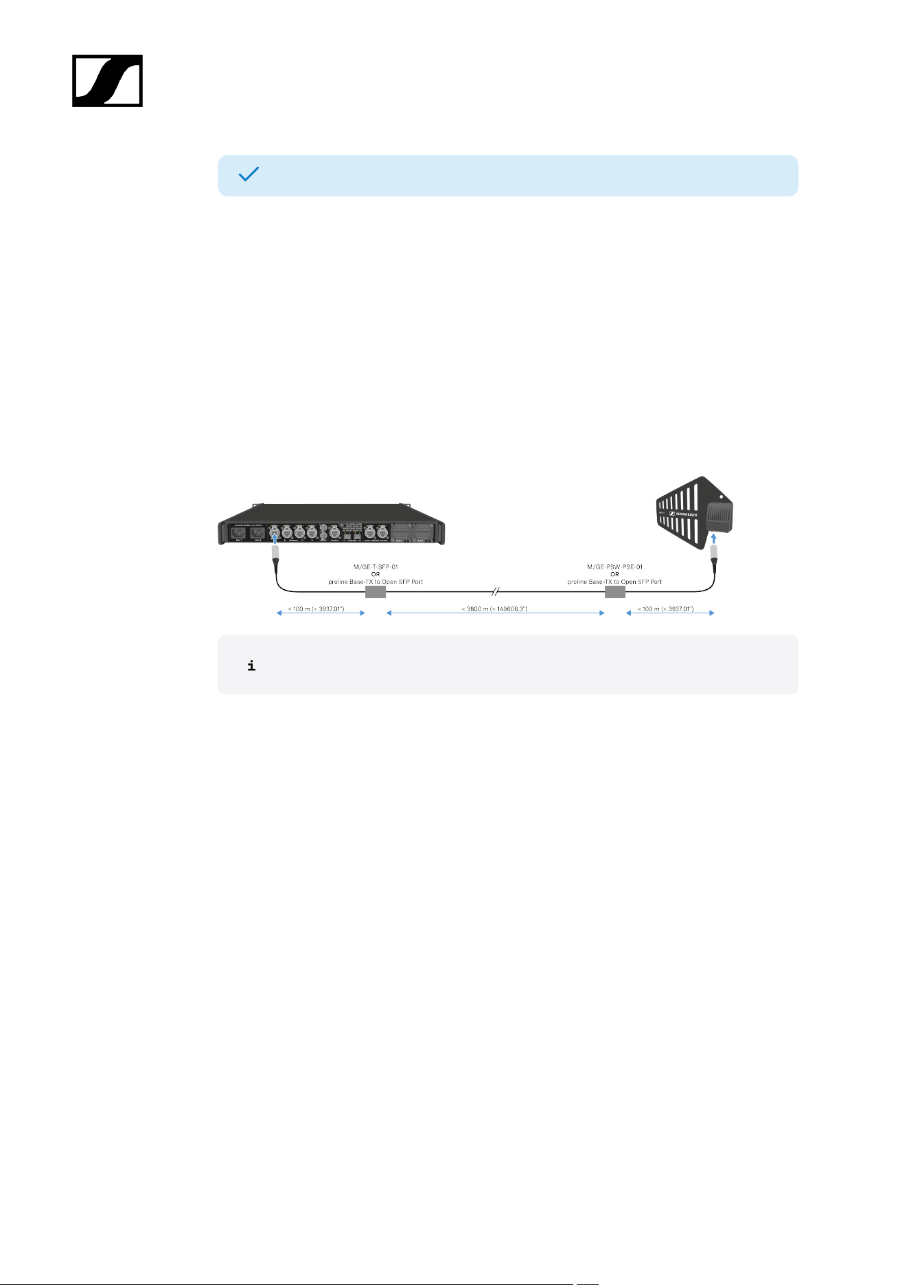
Antenna cable extension
Longer cable distances are possible with the use of fiber optic cables and media
converters.
Sennheiser tested the recommend converters for a complete distance of 4 km (157480.31").
We only recommend the following converters for fully tested functionality:
• Converter with PoE for DAD antenna Lantronix M/GE-PSW-PSE-01
• Converter for the Base Station Lantronix M/GE-T-SFP-01
• Converter for DAD antenna or Base Station proline Base-TX to Open SFP Port POE
The media converter must not have a switch function.
102
| 4 - User manual
Updating the DAD
The firmware of the antenna will update automatically, when connected to the Base Station.
NOTICE
Data loss during firmware update
The audio transmission is interrupted during the firmware update of the
Base Station, the antenna or the mobile device.
After the firmware update, the device is restarted automatically.
Do not update the firmware during an active live audio
transmission.
To update the firmware:
Connect the antenna to a Base Station. See Connecting/disconnecting the antenna.
To update the Base Station, see Updating the Base Station.
The LED is flashing green and red during the update.
The firmware has been updated.
103
| 4 - User manual
CHG 70N-C charger
The CHG 70N-C is a network enabled charger featuring two individual charging bays.
Compatible products:
• EW-DX SKM/EW-DX SKM-S handheld transmitter
• EW-DX SK/EW-DX SK 3-PIN bodypack transmitter
• SPECTERA SEK bidirectional transmitter
• BA 70 rechargeable battery
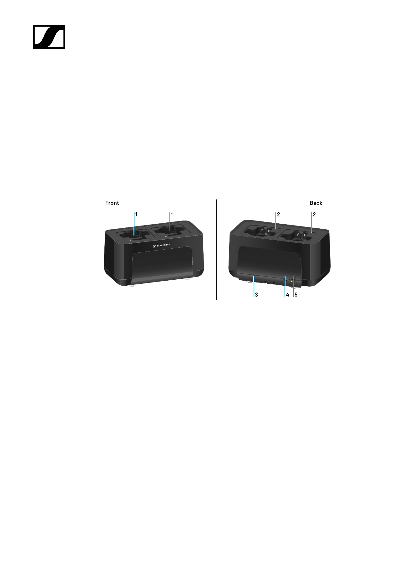
Product overview
1 Charging slots
• See Charging the rechargeable battery
2 Status LED of the charging slots
• See Charging the rechargeable battery
3 Reset button
• Press and hold for 10 seconds to reset the device’s network settings, see
Connecting a charger in a network
• Press and hold for 4 seconds to enable power saving mode, see Power saving
mode
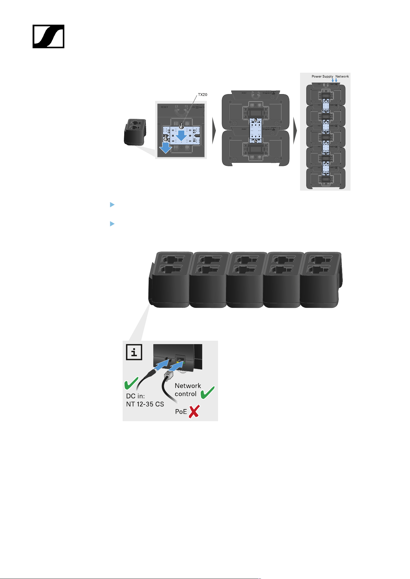
4 DC in connection socket for the NT 12-35 CS power supply unit
• See Connecting/disconnecting the charger to/from the power supply system
104

| 4 - User manual
5 PoE/Ethernet RJ45 socket for controlling the device over the network and for Power over
Ethernet power supply
• See Connecting a charger in a network
• See Connecting/disconnecting the charger to/from the power supply system
You can cascade up to 5 devices with only one power supply and one network
connection. See Cascading chargers.
105
| 4 - User manual
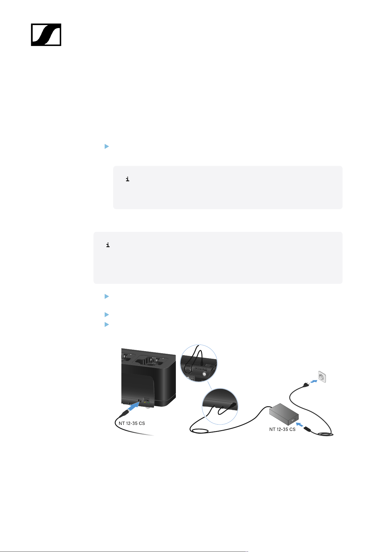
Connecting/disconnecting the charger to/from the power supply
system
You can operate the charger either with the Sennheiser NT 12-35 CS power supply unit
or with Power over Ethernet (PoE IEEE 802.3af Class 0). Please refer to the following
information.
Power from the NT 12-35 CS power supply unit
Use only the NT 12-35 CS power supply unit from Sennheiser. It is designed for your
charger and ensures safe operation.
The power supply unit is available either separately (Sennheiser article
number 508995) or together with the charger as a kit (see CHG 70N-C
network-enabled charger).
Power from the NT 12-35 CS power supply unit
Use only the NT 12-35 CS power supply unit from Sennheiser. It is designed
for your charger and ensures safe operation. The power supply unit is available
either separately (Sennheiser article number 508995) or together with the
charger as a kit (see CHG 70N-C network-enabled charger).
Connect the hollow jack plug of the power supply unit to the DC in socket on the
charger.
Pass the cable through the strain relief.
Plug the power supply unit into the wall outlet using the correct power cable for your
country.
106
| 4 - User manual
Disconnecting the charger completely from the power supply system
Unplug the mains cable from the wall socket.
Unplug the hollow jack plug of the power supply unit from the DC in socket on the
charger.
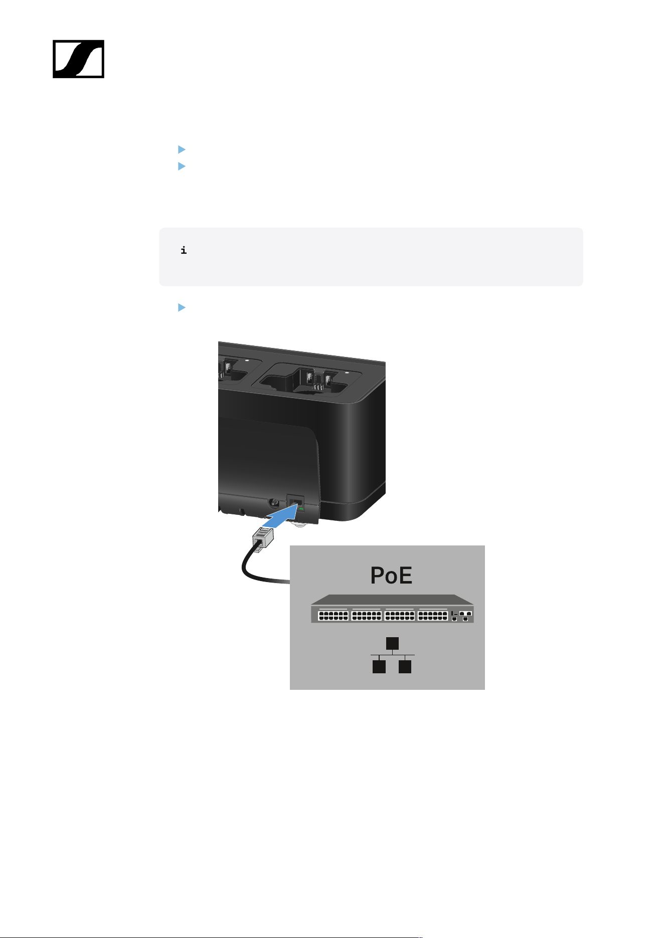
Power over Ethernet (PoE)
The charger can be powered via Power over Ethernet (PoE IEEE 802.3af Class
0).
Connect the charger to a PoE-enabled network switch.
107
| 4 - User manual
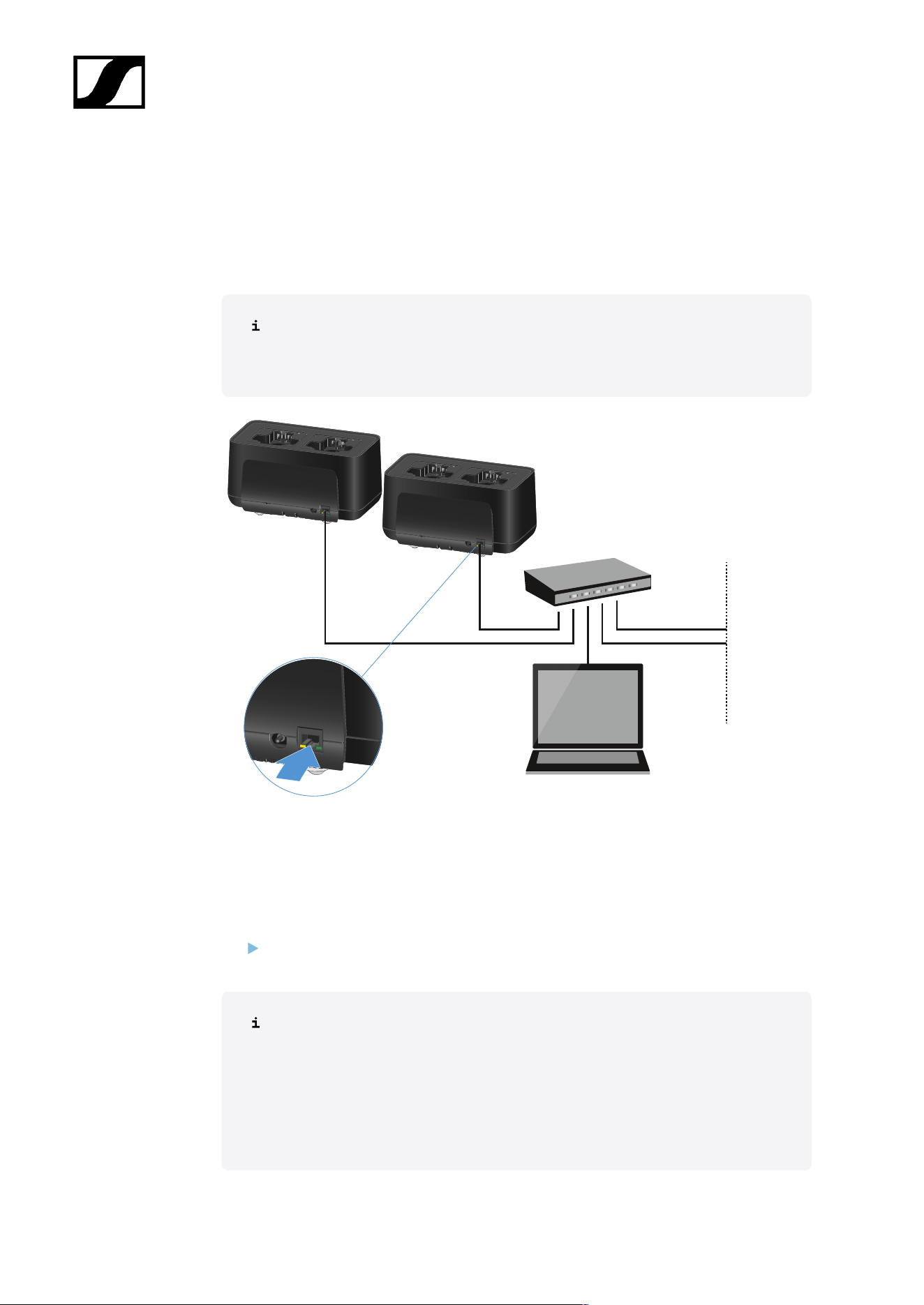
Connecting a charger in a network
You can monitor and control one or more chargers via a network connection using the
Sennheiser Wireless Systems Manager (WSM) or Sennheiser Control Cockpit (SCC)
software.
The network does not have to be a homogeneous network including only
chargers. You can integrate the charger into your existing network infrastructure
with any other types of devices.
You can integrate the devices into the network individually or cascade up to 5 chargers (see
Cascading chargers).
To reset the network settings to their factory defaults:
Hold the Reset button for 4 seconds.
For more information about controlling devices via the Sennheiser Wireless
Systems Manager or Sennheiser Control Cockpit software, refer to the
instruction manual for the software. You can download the software here:
sennheiser.com/wsm
sennheiser.com/scc
108
| 4 - User manual
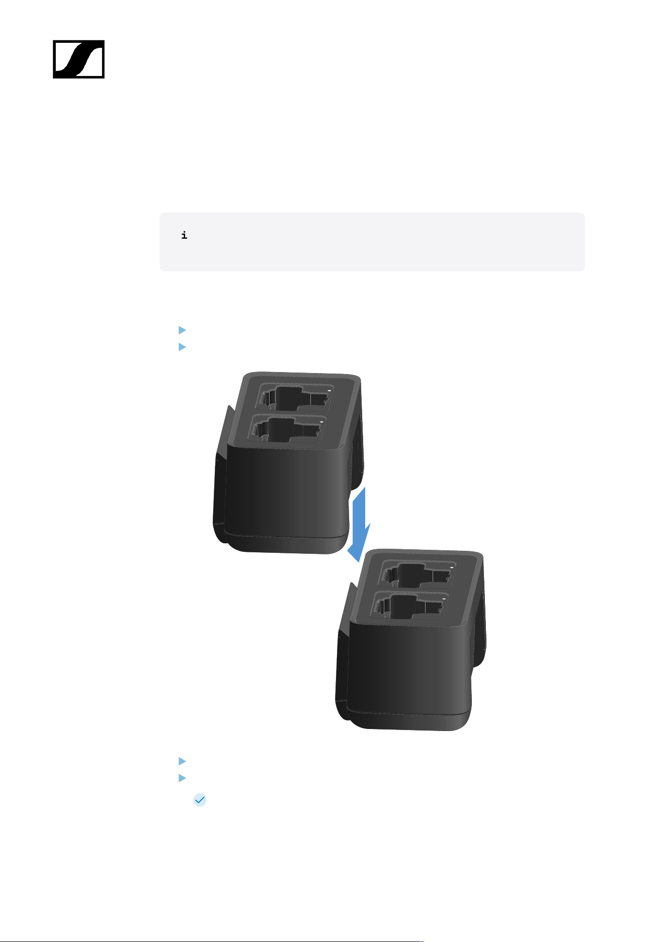
Cascading chargers
You can cascade up to five CHG 70N-C chargers and operate them with a single power
supply and a single network connection. This minimizes the cabling required for larger
systems.
The power must be supplied via the NT 12-35 CS power supply unit. Power over
Ethernet (PoE) is not possible when cascading.
To cascade the chargers:
Make sure that no chargers are connected to the power before you start.
Plug the chargers into each other as shown in the figure.
Detach the connecting rail on the bottom of the charger.
Fasten the connecting rail beneath two chargers as shown in the figure.
The power and the network connection are passed on to all devices via the
connecting rails.
109
| 4 - User manual
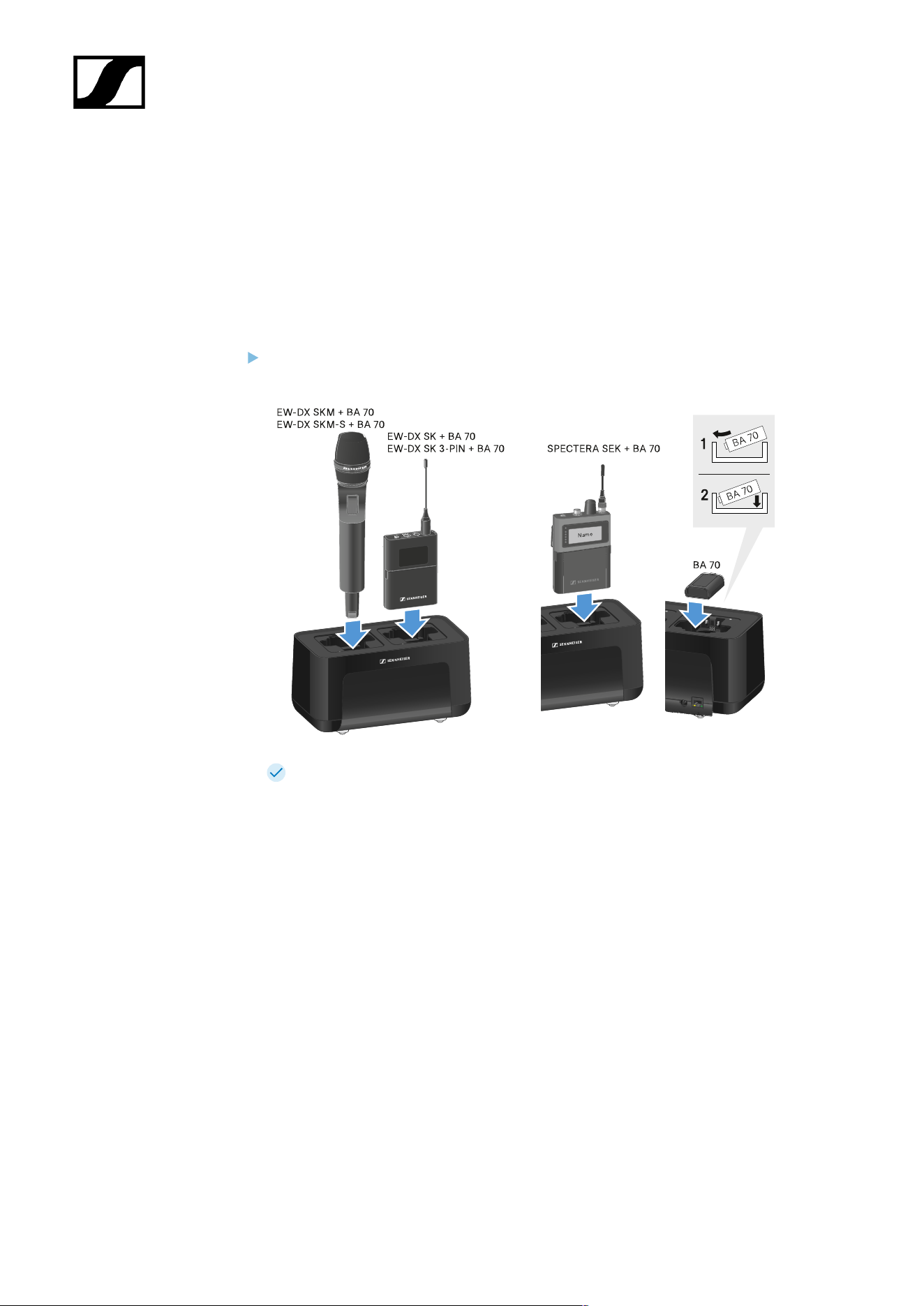
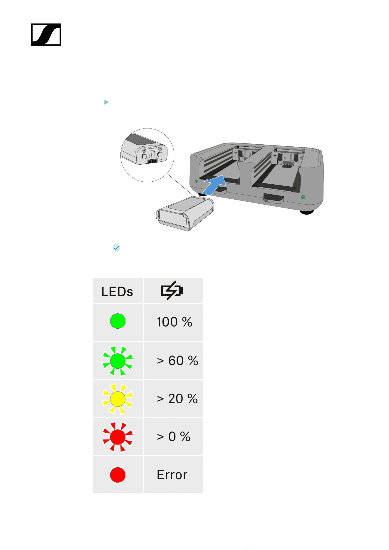
Charging the rechargeable battery
You can use the CHG 70N-C charger to charge individual BA 70 rechargeable batteries, or to
charge EW-DX SKM, EW-DX SKM-S, EW-DX SK, EW-DX SK 3-PIN or Spectera SEK with the
BA 70 rechargeable battery already inserted.
To charge the battery:
Insert the individual rechargeable battery or the transmitter with battery already
inserted into the charging slot as shown in the figure.
The rechargeable battery will begin charging.
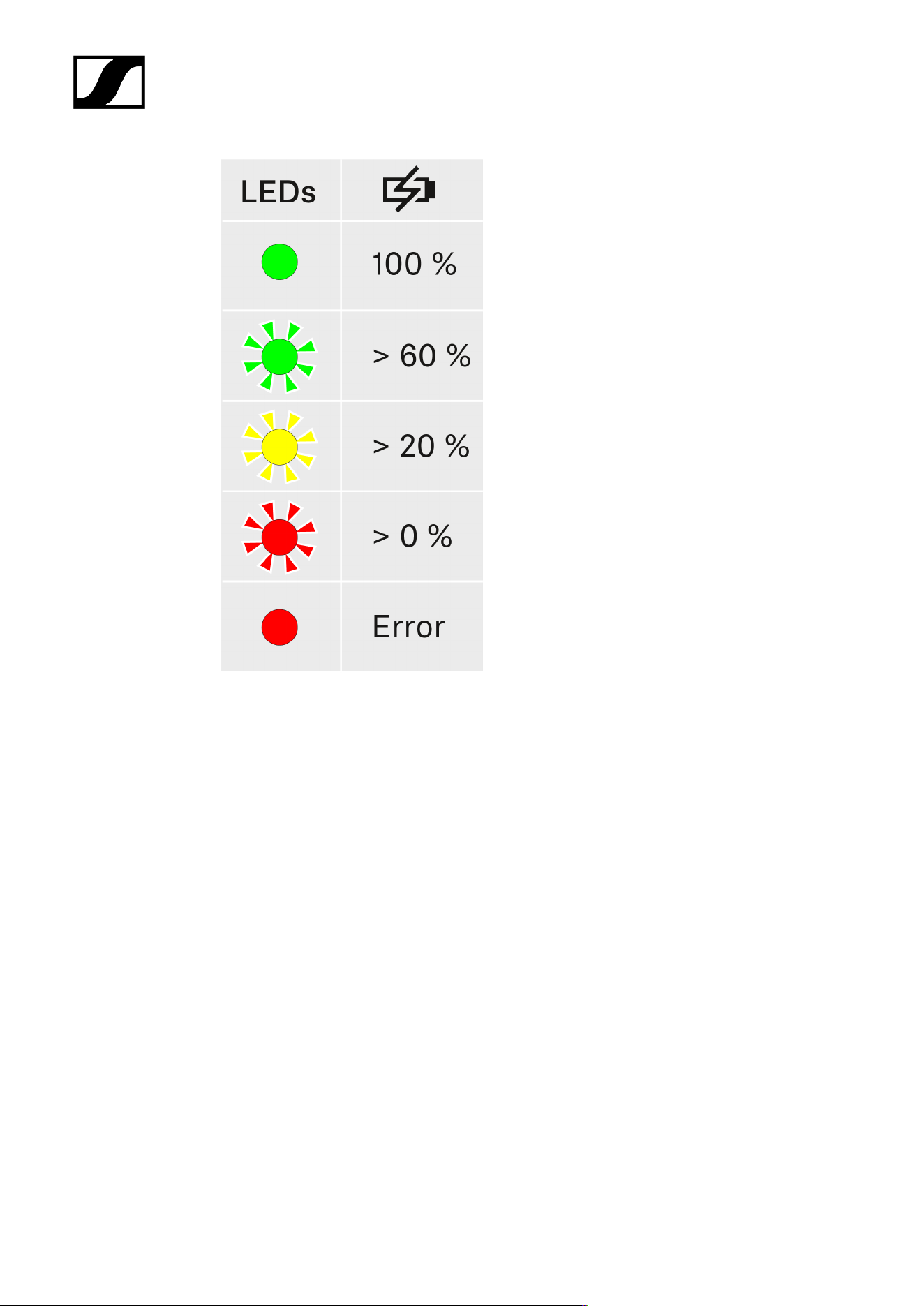
The LED on the charging slot shows the battery’s charge level.
111
| 4 - User manual
112

| 4 - User manual
Power saving mode
In power saving mode, the transmitters are charged only once. The charger also does not
provide any trickle charge.
To activate power saving mode:
In power saving mode, the CHG 70N-C cannot be controlled over the network.
Remove all transmitters and/or rechargeable batteries from the charging slots.
Hold the Reset button for 4 seconds.
The charging slot LEDs light up purple.
Insert the rechargeable battery/transmitter for charging.
The rechargeable battery will begin charging. The charging slot LED turns green
once it reaches full charge.
To deactivate power saving mode:
Disconnect the charger from the power supply system.
Then reconnect it to the power supply system.
The charger will start up in the configuration that was set before you activated
power saving mode.
113
| 4 - User manual
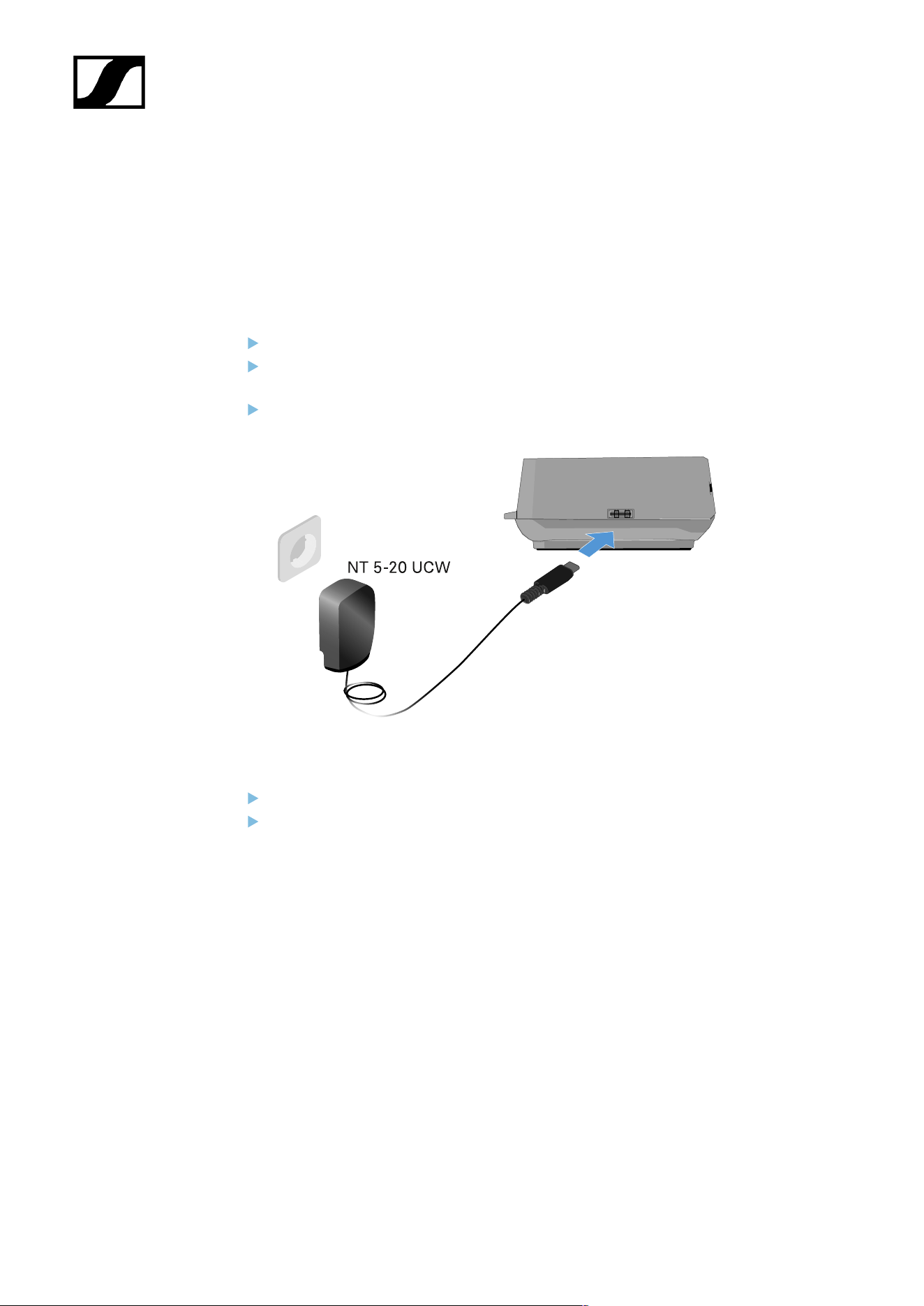
L 70 USB charger
Connecting/disconnecting the charger to/from the power supply
system
To connect the charger to the power supply system:
Use only the NT 5-20 UCW power supply unit from Sennheiser.
Connect the USB-C plug on the charging cable to the USB-C port on the side of the
charger.
Plug the power supply unit with the correct country adapter into a suitable power
outlet.
To disconnect the charger from the power supply system:
Unplug the power supply unit from the wall socket.
Remove the USB-C plug on the charging cable from the USB-C port on the side of the
charger.
114
| 4 - User manual
Charging the rechargeable battery
To charge the BA 70 rechargeable battery in the L 70 USB charger:
Slide the rechargeable battery completely into the charging slot as shown in the
figure.
The rechargeable battery will begin charging.
The LED on the charging slot shows the battery’s charge level:
115
| 4 - User manual
Modular L 6000 charger
These sections contain information about installing, starting up and operating the modular
L 6000 charger and the corresponding charging modules.
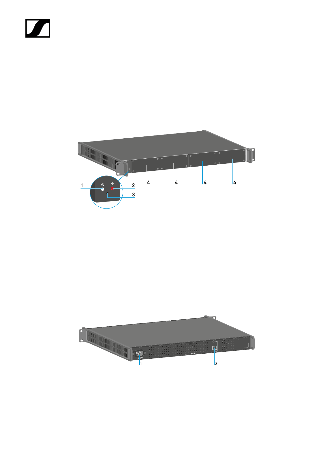
Product overview
Front
1 Power status LED
See Meaning of the LEDs
2 Warning status LED
See Meaning of the LEDs
3 Reset
See Resetting settings (factory reset)
4 Dummy caps
See Installing a charging module in the L 6000 charger
Back
1 Power socket
See Connecting/disconnecting the L 6000 to/from the power supply system
2 Ethernet socket
See Connecting the L 6000 to a network
116
| 4 - User manual
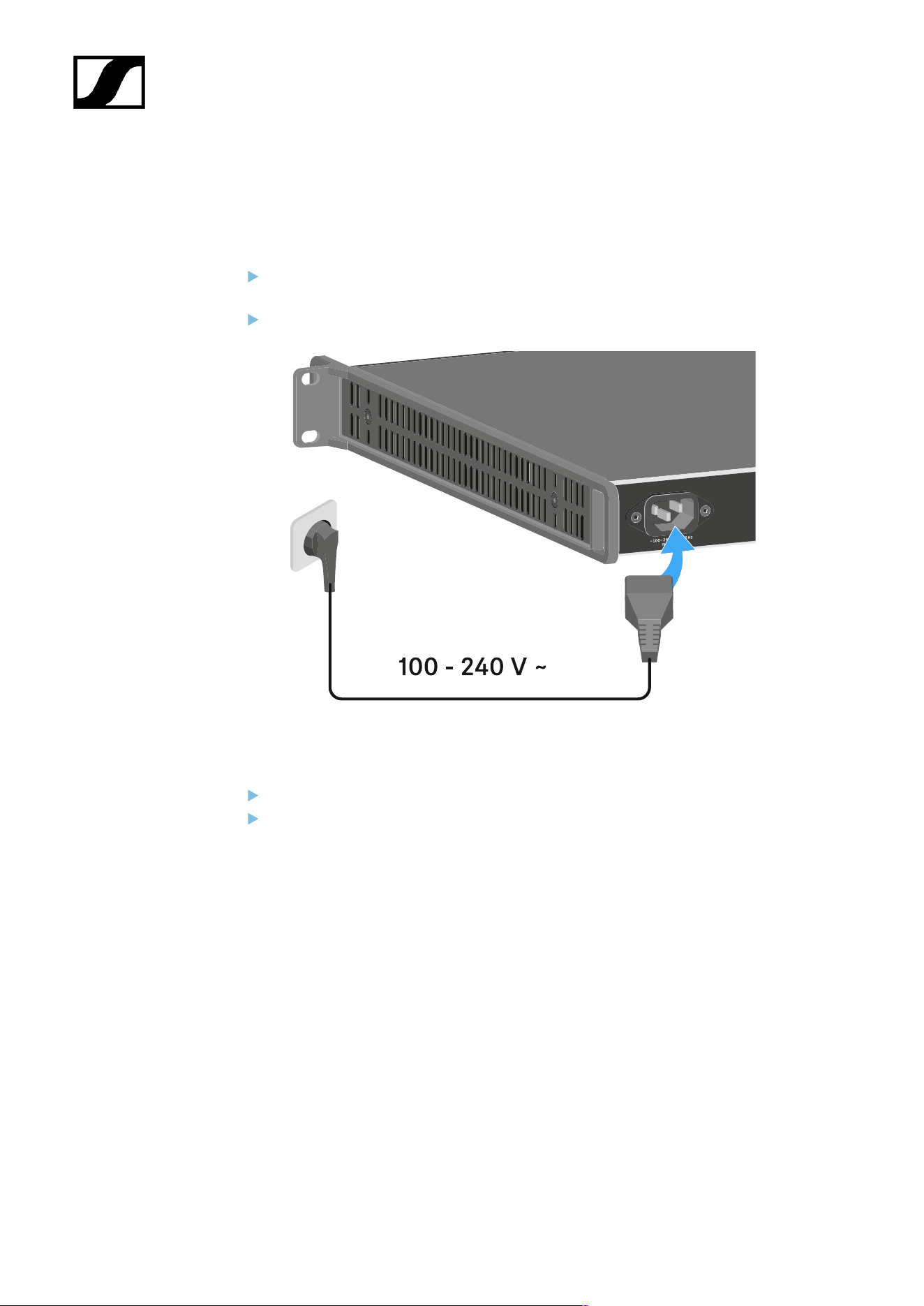
Connecting/disconnecting the L 6000 to/from the power supply
system
To connect the L 6000 to the power supply system:
Connect the mains cable IEC connector to the power socket on the rear side of the L
6000.
Connect the mains cable plug into a suitable wall socket.
To completely disconnect the L 6000 from the power supply system:
Unplug the mains cable plug from the wall socket.
Unplug the mains cable IEC connector from the power socket on the rear side of the L
6000.
117
| 4 - User manual
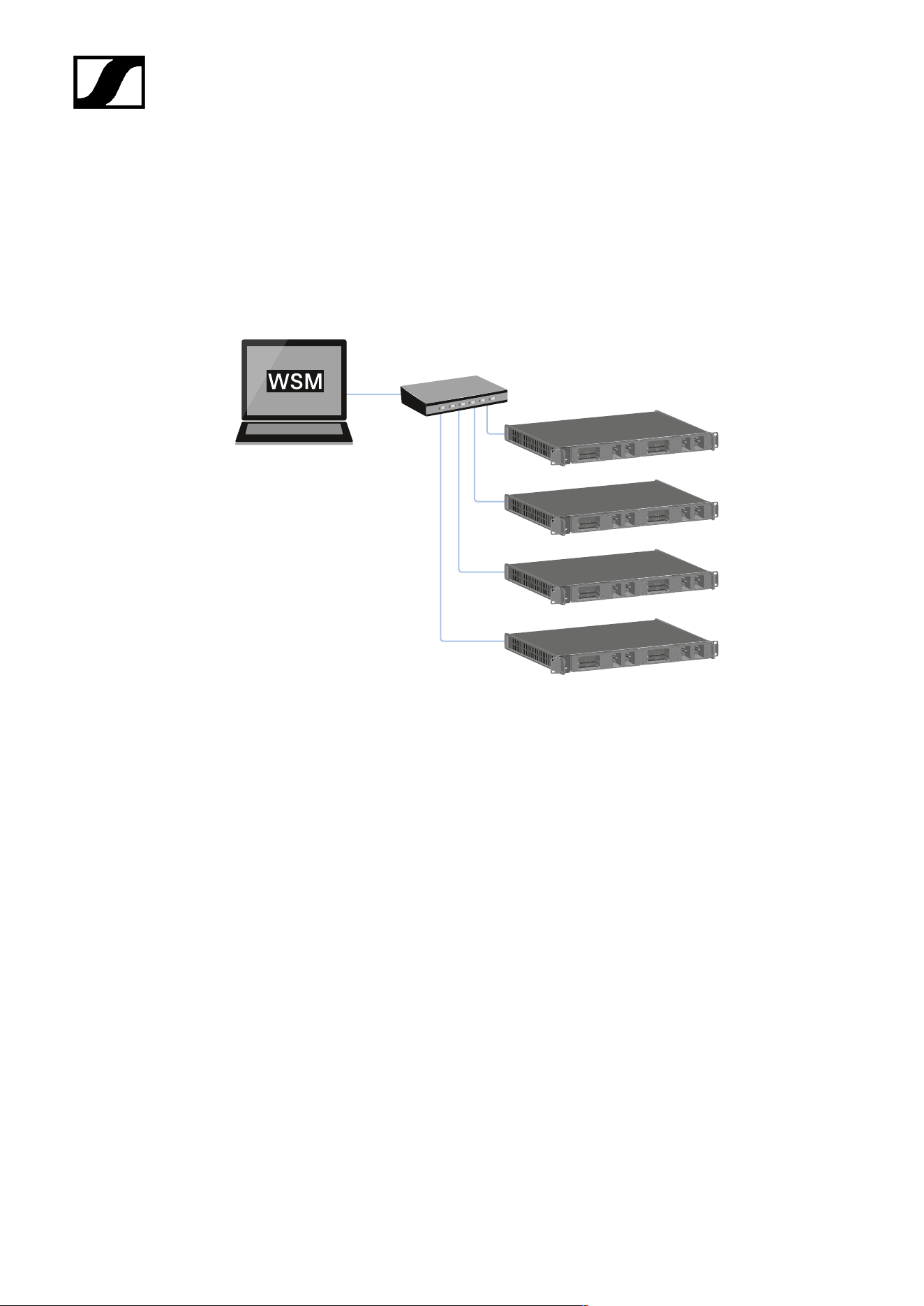
Connecting the L 6000 to a network
You can monitor and control one or more L 6000s via a network connection using the
Sennheiser Wireless Systems Manager (WSM) software.
The network does not have to be a homogeneous network including only chargers. You can
integrate the L 6000 into your existing network infrastructure with any other types of devices.
118
| 4 - User manual
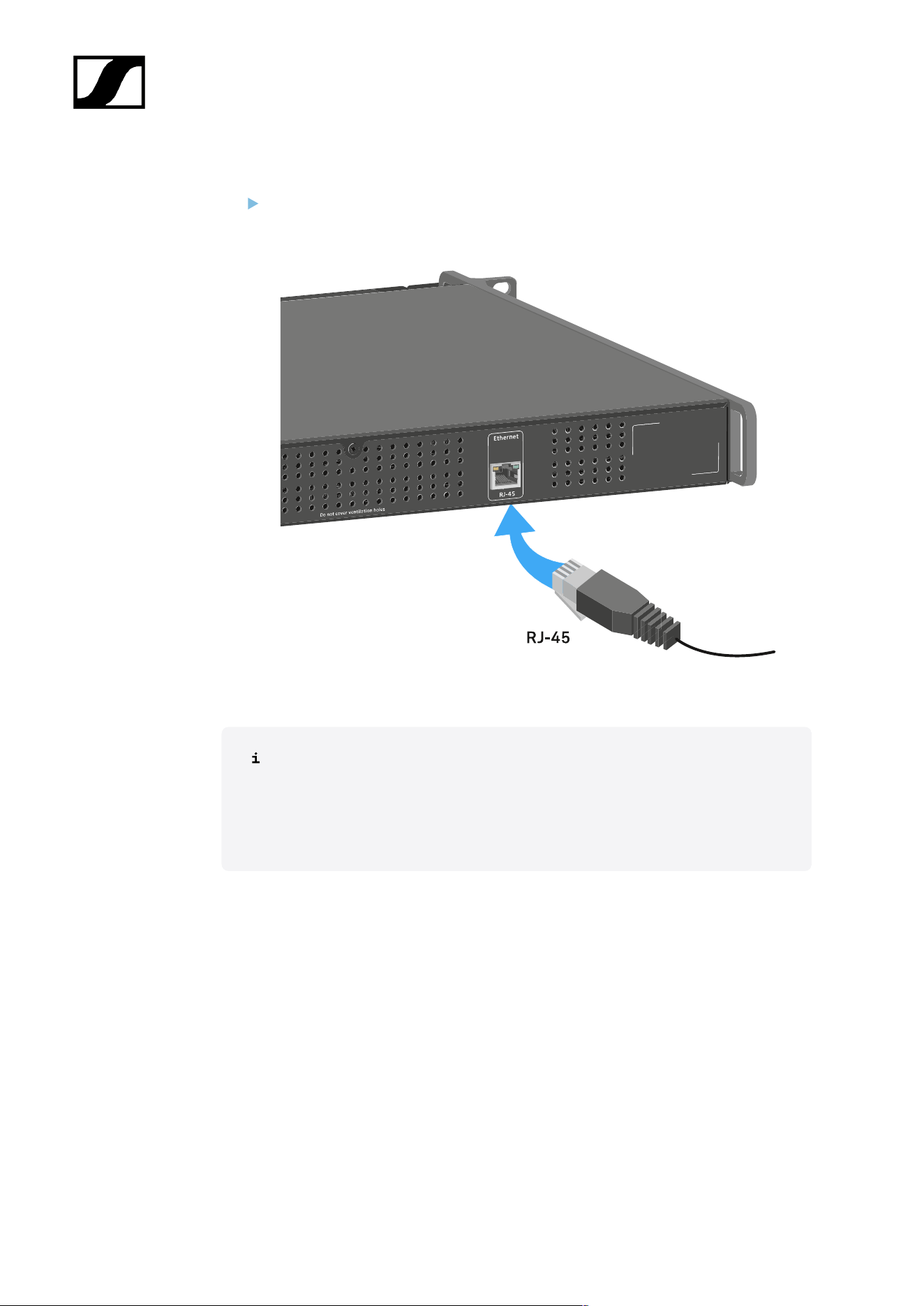
To connect the L 6000 to a network:
Connect a network cable with an RJ-45 connector (Cat5 at minimum) to the Ethernet
socket on the rear side of the L 6000.
For more information about controlling devices via the Sennheiser Wireless
Systems Manager (WSM) software, refer to the instruction manual for the
software. You can download the software here:
sennheiser.com/wsm
119
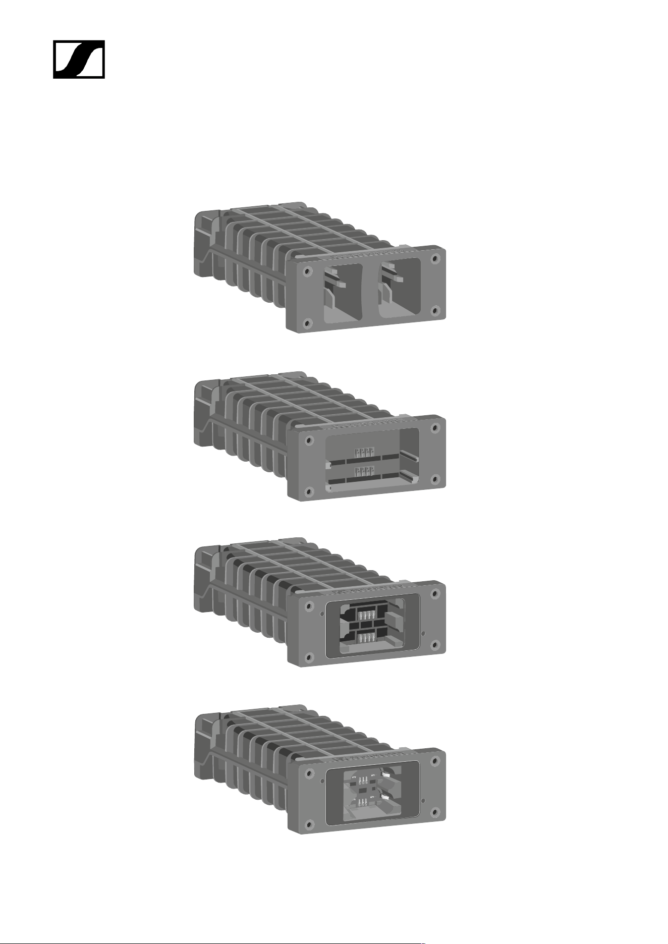
| 4 - User manual
Installing a charging module in the L 6000 charger
The following charging modules are available for the L 6000 charger.
• LM 6060 -> for charging the BA 60 rechargeable battery
• LM 6061 -> for charging the BA 61 rechargeable battery
• LM 6062 -> for charging the BA 62 rechargeable battery
• LM 6070 -> for charging the BA 70 rechargeable battery
120
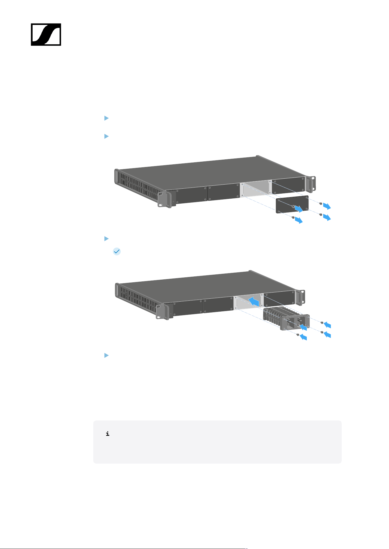
| 4 - User manual
You can combine the LM 6060, LM 6061, LM 6062 and LM 6070 in any way in the L 6000
charger.
To install a charging module in the L 6000 charger:
Completely disconnect the L 6000 charger from the power supply system. See
Connecting/disconnecting the L 6000 to/from the power supply system.
Unscrew one of the dummy caps on the L 6000.
To do so, you require a Torx 10 screwdriver.
Fully slide the charging module into the open charging slot as shown in the figure.
The charging module can be inserted into the L 6000 housing only in one
direction. The Sennheiser lettering on the charging module must face upward.
Tightly screw on the charging module.
Always use the latest firmware for the L 6000 charger (version 2.0 or later) to ensure you
have access to the full range of functions. You can download the latest firmware from the
following address:
sennheiser.com/l-6000
For more detailed information about charging the BA 60, BA 61 and BA 62 and
BA 70 rechargeable batteries, see Charging the rechargeable batteries in the
L 6000 charger.
121
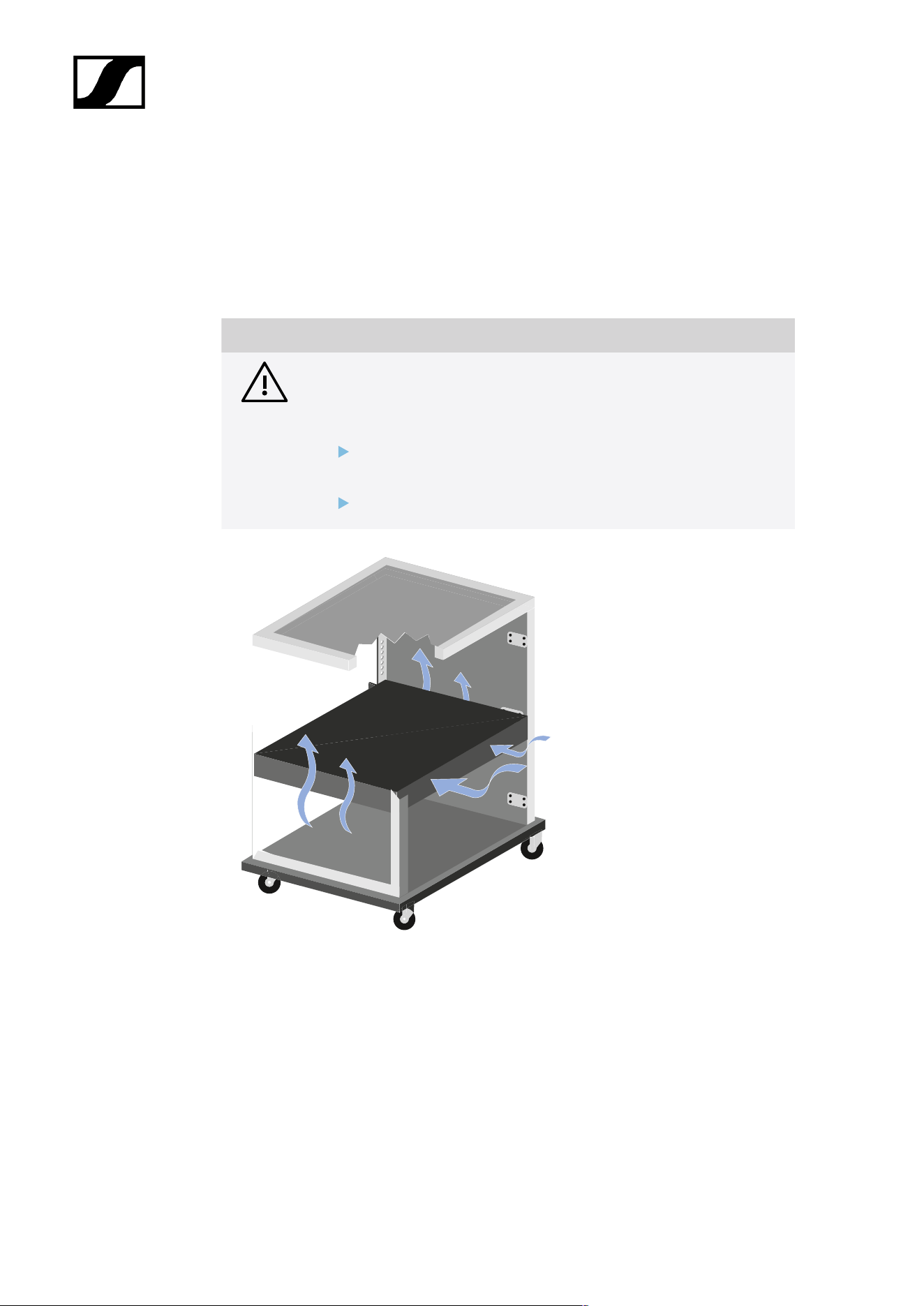
| 4 - User manual
Installing the L 6000 in a rack
You can install the L 6000 charger in any conventional 19" rack.
The rack mounting angles are already attached to the device.
Always observe the following information during rack mounting.
NOTICE
Material damages caused by devices overheating
When there is insufficient ventilation, the devices mounted in the rack
may overheat.
Ensure that there is sufficient ventilation in the rack, particularly
if several devices are installed.
If necessary, install a fan in the rack.
122
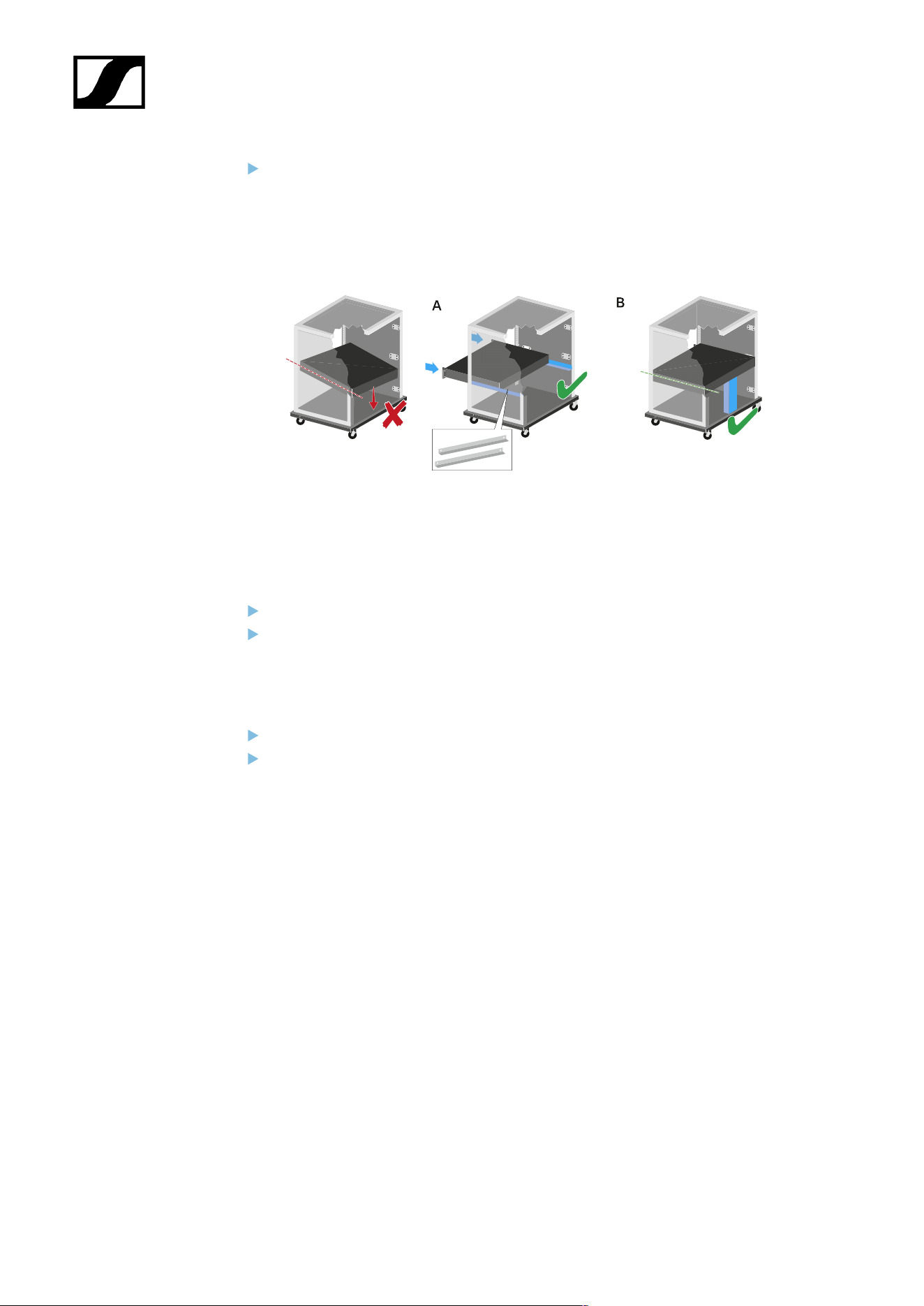
| 4 - User manual
Support the EM 6000 after installation in the rack. Due to the weight and depth of
the device, there is a risk that it may break off in the rack and become damaged as a
result.
Version A:
Use special rack mounting rails.
The design of the rack used must be suitable for the installation of these mounting
rails.
Version B:
Use a suitable object to support the device on the rear side.
Ensure that this object cannot become loose.
123

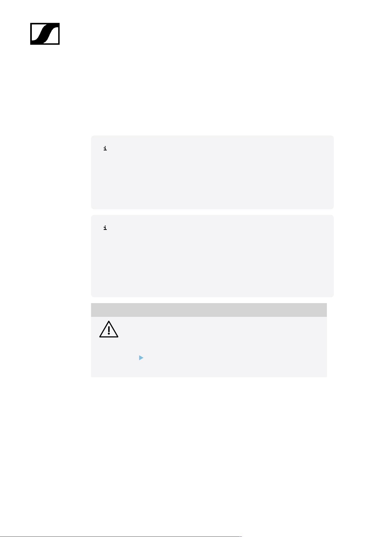
| 4 - User manual
Charging the rechargeable batteries in the L 6000 charger
To charge the BA 60, BA 61, BA 62 and BA 70 rechargeable batteries with the L 6000
charger, you need the LM 6060, LM 6061, LM 6062 or LM 6070 charging modules.
Before charging, you have to install the charging modules in the L 6000 charger. For
installation information, see Installing a charging module in the L 6000 charger.
Note on the charger firmware
Always use the latest firmware for the L 6000 charger (version 2.0 or later) to
ensure you have access to the full range of functions. You can download the
latest firmware from the following address:
sennheiser.com/l-6000
Note on the BA 62 rechargeable battery for the SK 6212 bodypack transmitter
It is possible that new rechargeable batteries cannot be fully charged to 100 %
in the first few charging cycles.
The remaining operating time may still be unclear after the first few charging
cycles. This will improve over time after more charging cycles because the
rechargeable battery calibrates itself.
NOTICE
Damage to the charging contacts in the charging slot
If you touch the contacts in the charging slot, they may become dirty or
bent.
When replacing and removing the rechargeable batteries, ensure
that you do not touch the charging contacts in the charging slots.
125
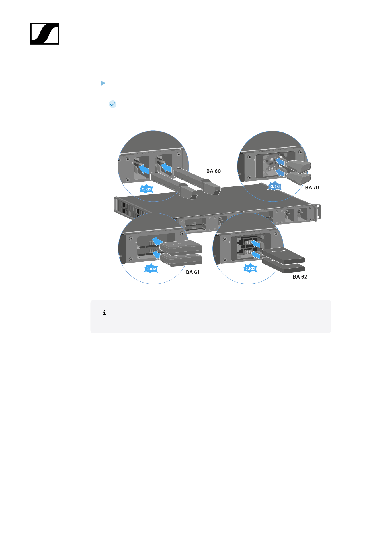
| 4 - User manual
To charge the rechargeable batteries:
Insert the rechargeable battery into the charging module as shown in the figure until it
audibly clicks into place.
The rechargeable batteries can be inserted into the charging modules only in one
direction. You can see the charge level of the rechargeable batteries from the LEDs on
the charging modules (see Meaning of the LEDs).
At ambient temperatures of 45° C (113° F) and above, the rechargeable batteries
can no longer be fully charged. They can only be charged to a maximum of 70 %.
126
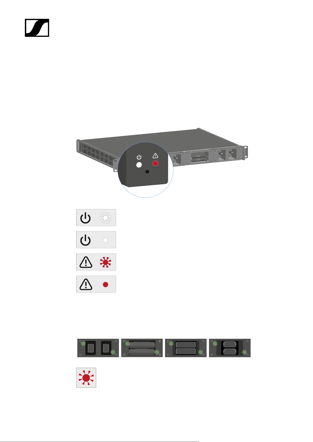
| 4 - User manual
Meaning of the LEDs
You can read the following information from the LEDs on the L 6000 charger and the LM
6060, LM 6061, LM 6062 and LM 6070 charging modules:
L 6000 status LEDs
The L 6000 charger has two status LEDs on the front of the device to the left.
White LED flashing >> device is starting or firmware is being updated
White LED illuminated >> device is ready for operation
Red LED flashing >> fan is damaged
Red LED illuminated >> device is too hot or too cold and the charging
process was stopped
LM 6060 | LM 6061 | LM 6062 | LM 6070 status LEDs
The LM 6060, LM 6061, LM 6062 and LM 6070 modules each have two charging slots. Next
to each charging slot, there is a status LED that displays the following status information:
Flashing red >> the charging slot or rechargeable battery is too hot or too cold
and the charging process was stopped.
127
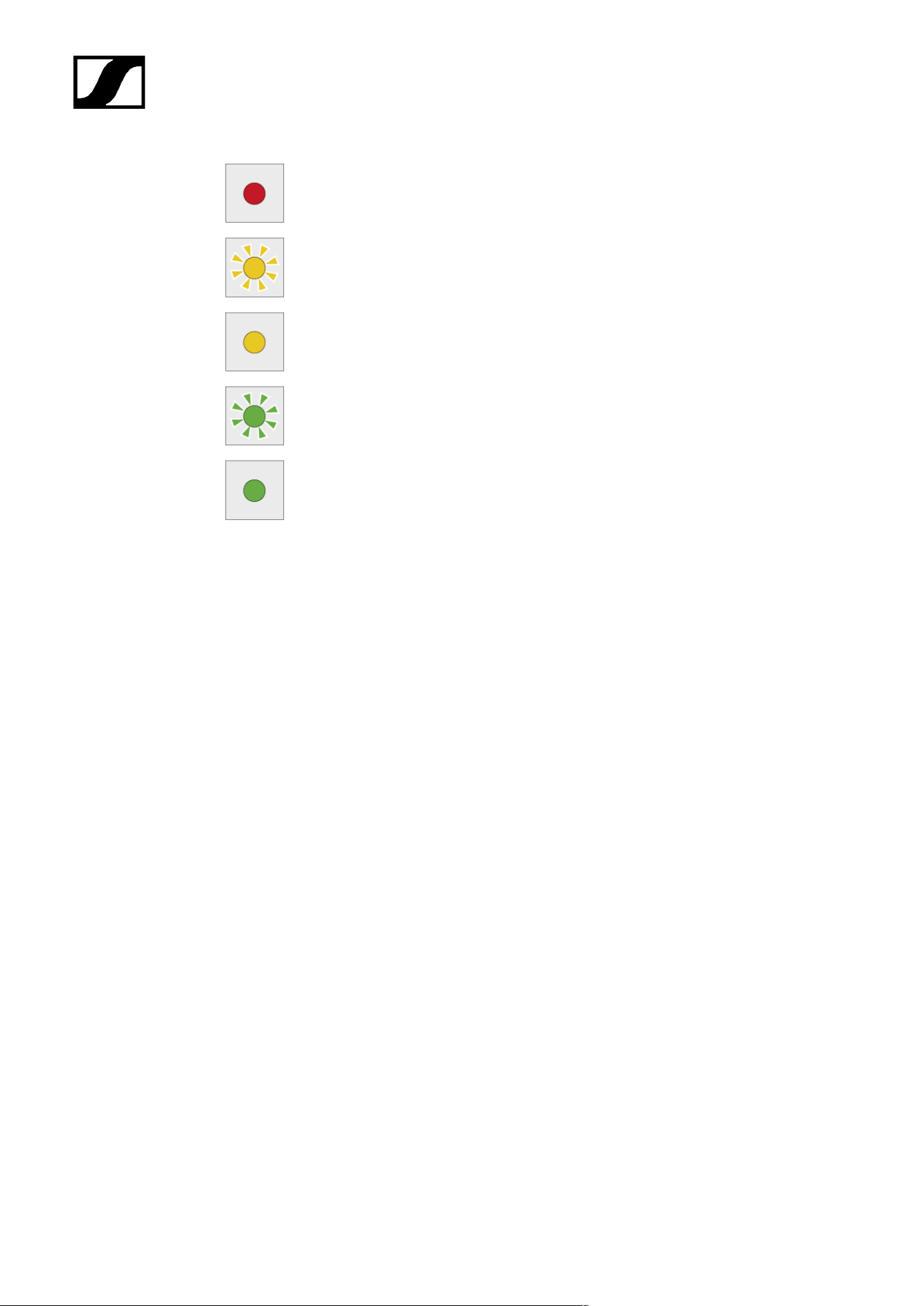
| 4 - User manual
Lights up red >> the rechargeable battery is defective.
Flashing yellow >> the rechargeable battery is being regenerated.
Lights up yellow >> the rechargeable battery is being charged. Charge level 0%
to 80%
Flashing green >> the rechargeable battery is being charged. Charge level 81%
to 96%
Lights up green >> the rechargeable battery is fully charged. Charge level 100%
LM 6060, LM 6061, LM 6062 and LM 6070 status LEDs in storage mode
If you are operating the L 6000 charger in storage mode via WSM, the meaning of the status
indicators changes. You can find more information under Preparing rechargeable batteries
for storage (storage mode).
128
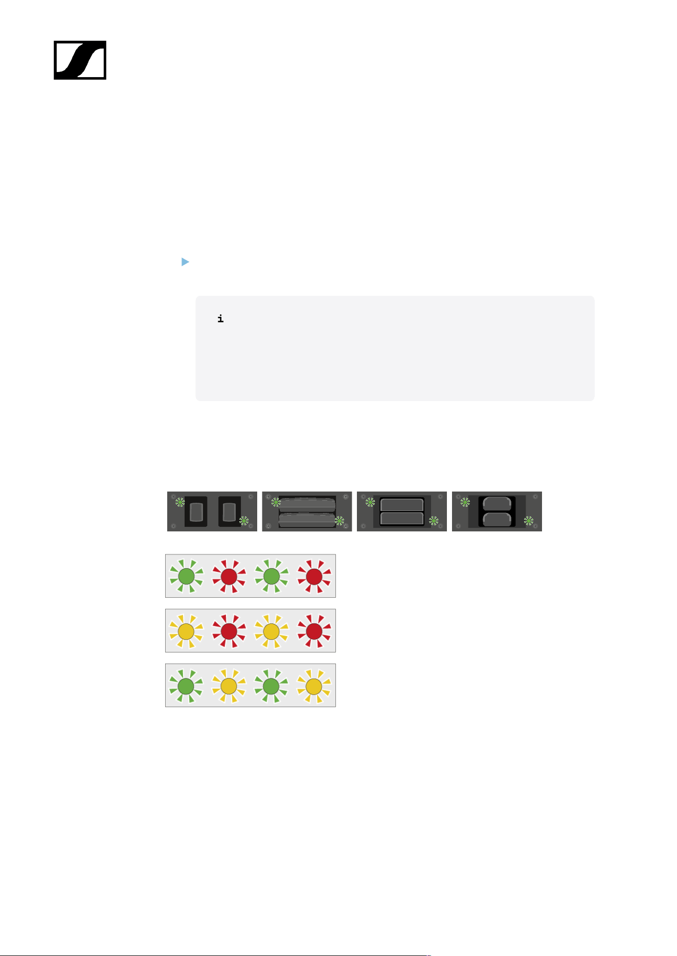
| 4 - User manual
Preparing rechargeable batteries for storage (storage mode)
If you are not using the rechargeable batteries for a longer period of time and therefore want
to store them, the rechargeable batteries should have a charge of approx. 70%.
You can set this level using the storage mode from the Sennheiser Wireless Systems
Manager (WSM) software.
To do so, connect the L 6000 charger to a network (see Connecting the L 6000 to a
network) and establish the connection with the WSM software.
For more information about controlling devices via the Sennheiser
Wireless Systems Manager (WSM) software, refer to the instruction
manual for the software. You can download the software here:
sennheiser.com/wsm
Meaning of the status LEDs in storage mode
In storage mode, the status LEDs next to the individual charging slots show the following
status information:
Flashing green/red >> rechargeable battery not
inserted.
Flashing yellow/red >> the rechargeable battery is
being charged or discharged to 70%.
Flashing green/yellow >> the rechargeable battery
has reached the storage charge level of 70%.
129
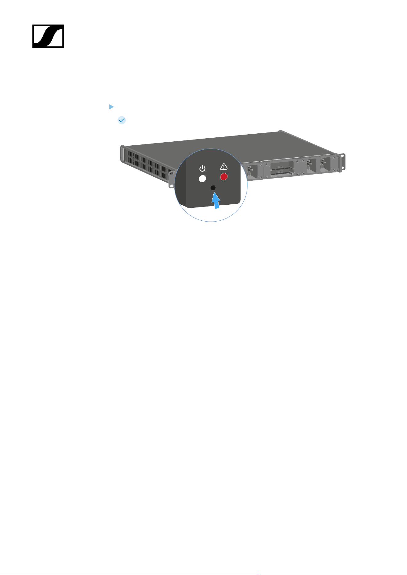
| 4 - User manual
Resetting settings (factory reset)
To reset the L 6000 charger settings to the factory settings:
Use a pointed object to press the Reset button on the front of the L 6000 charger.
The settings are reset to the factory settings.
130

| 4 - User manual
Updating the firmware
You can update the firmware for the L 6000 charger using the Sennheiser Wireless Systems
Manager (WSM) software.
To do so, connect the L 6000 charger to a network (see Connecting the L 6000 to a
network) and establish the connection with the WSM software.
For more information about controlling devices via the Sennheiser
Wireless Systems Manager (WSM) software, refer to the instruction
manual for the software. You can download the software here:
sennheiser.com/wsm
You can find the latest firmware on the Digital 6000 product page or in the
Sennheiser website’s download area:
sennheiser.com/digital-6000
sennheiser.com/download
131

| 4 - User manual
Operating the L 6000 via a network
You can use the Sennheiser Wireless Systems Manager software to operate the charger via
a network connection.
To do so, connect the L 6000 charger to a network (see Connecting the L 6000 to a
network) and establish the connection with the WSM software.
For more information about controlling devices via the Sennheiser
Wireless Systems Manager (WSM) software, refer to the instruction
manual for the software. You can download the software here:
sennheiser.com/wsm
You can perform the following actions using WSM:
• Update the L 6000 charger firmware
• Prepare rechargeable batteries for storage (see Preparing rechargeable batteries for
storage (storage mode)).
132
| 4 - User manual
Cleaning and maintenance
Note the following information when cleaning and maintaining products of the Spectera
series.
NOTICE
Liquids can damage the electronics of the product
Liquids entering the product housing can cause a short-circuit and
damage the electronics.
Keep all liquids away from the products.
Do not use any solvents or cleansing agents.
Disconnect the mains-operated products from the power supply
system and remove rechargeable batteries and batteries (if
present) before you begin cleaning.
Clean all products only with a soft, dry cloth.
Note the special cleaning instructions below for the following products.
Replacing the Base Stations fan filter
Check the filter from time to time and replace it if necessary. See Changing the fan
filter.
Cleaning the L 70 USB and CHG 70N chargers
Remove all rechargeable batteries from the charging slots.
Disconnect the charger from the power supply system before cleaning.
Clean the product with a dry cloth.
In addition, use a brush to remove dust from the charging slots.
Clean the charging contacts from time to time with a cotton swab, for instance.
133

Spectera
5. Knowledge base
Central hub for information, resources, and guides with further content on the product and/
or service.
Network guide
This network guide is intended for IT administrators, system integrators and event
technicians and serves as an planning and configuration guide for integrating components
of the Spectera offering into diverse network environments from small home networks up to
enterprise networks.
The guide contains recommendations on network setup for transmission of control data and
audio content (via Dante®).
General requirements
Operating systems
The Spectera Base Station as network device is able to be controlled by network-capable
PC or Mac devices.
The following system requirements apply for operation with Spectera WebUI and Sennheiser
LinkDesk:
System requirements
Recommended for Host PC Client
• Intel i5 Dual Core processor/M1 Mac/or similar
• 16 GB RAM
• At least 4 GB hard disk space (5 GB for Mac devices)
• Gigabit LAN interface
• Windows® 10, 11, Server 2019, Server 2022 (x64) or higher
• Mac OS Big Sonoma or later
• IPv4 network
Supported web browsers for Spectera WebUI
• Google Chrome: 125 or later
• Microsoft Edge: 125 or later
• Mozilla Firefox: 128 or later
• Apple Safari: 17 or later
• JavaScript must be activated
134
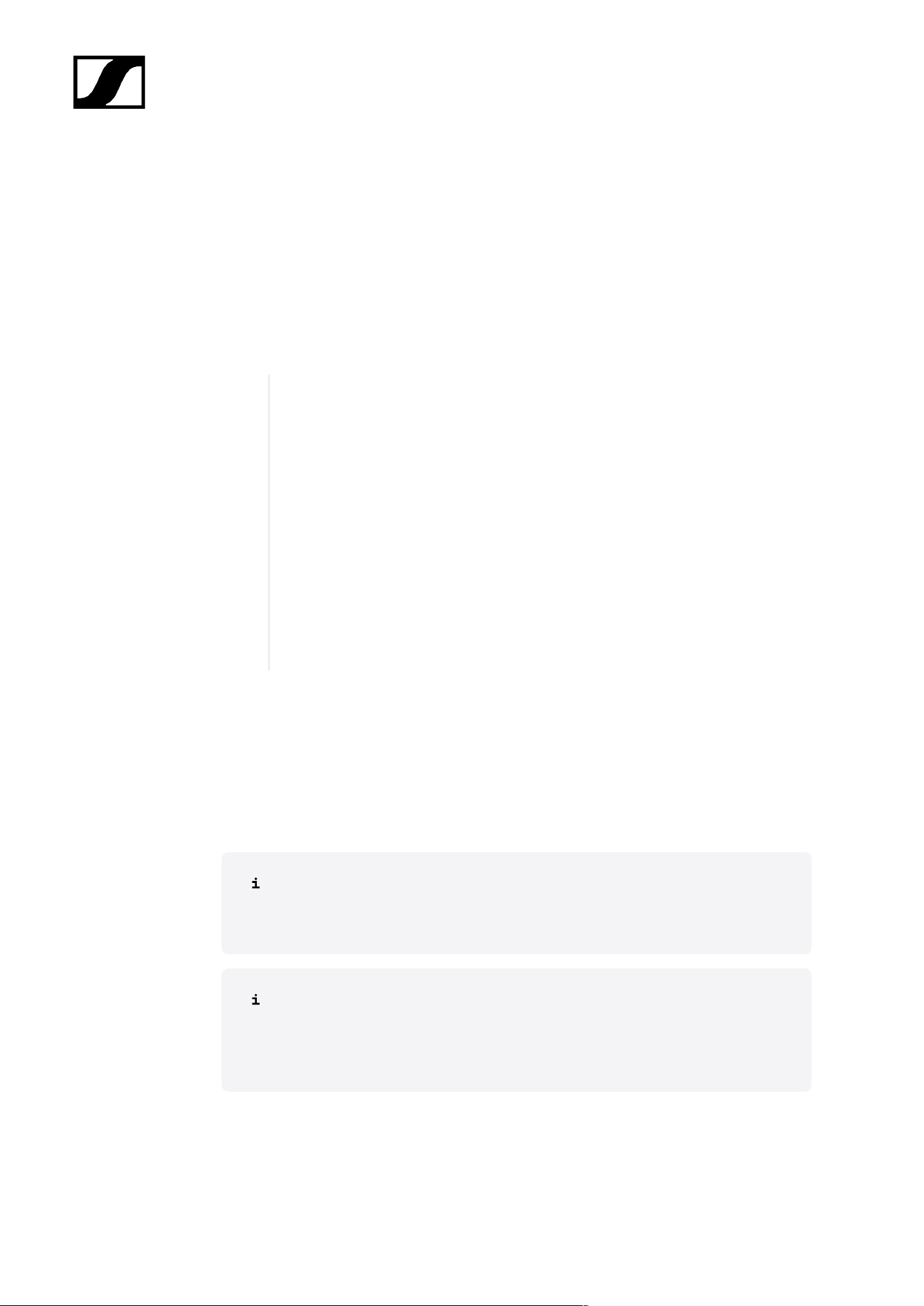
| 5 - Knowledge base
Network
Bandwidth and speed
When it comes to bandwidth requirements for high-quality audio, there are a number of
factors that can affect the input and output of the audio. The network speed required for
especially audio transmission via Dante® should be as high as possible to ensure a smooth
listening experience. As a rule, the minimum bandwidth for transmitting and receiving audio
at the Spectera Base Station is approximately the following:
“The majority of audio used in professional settings is PCM (uncompressed),
sampled at 48 kHz and a bit depth (word length) of 24 bits. Dante® audio is
unicast by default but can be set to use multicast for cases of one-to-many
distribution.
• Dante® packages audio into flows to save on network overhead.
• Unicast Audio flows contain up to 4 channels. The samples-per-
channel can vary between 4 and 64, depending on the latency setting
of the device. Bandwidth usage is about 6 Mbps per typical unicast
audio flow.
• Bandwidth for multicast flows is dependent on the number of audio
channels used. Bandwidth is about 1.5 Mbps per channel.
”
Source: Audinate Dante Information for Network Administrators (PDF)
Internet access
For both components Spectera Base Station and Sennheiser LinkDesk we recommend to
provide permanent Internet access. Please refer to chapter Ports, protocols and services to
get more details about used Internet services.
At least for the initial product activation of the Spectera Base Station and for
the use of the optional Sennheiser Account Login in Sennheiser LinkDesk it is
mandatory to have a direct Internet access and DNS support.
At the moment it is not possible to manually configure any network proxy and
DNS server at Spectera Base Station. Please make sure to provide direct Internet
access e.g. via white-listing the device and any used port, protocol and domain
and using DHCP to provide DNS server settings.
135

| 5 - Knowledge base
Network infrastructure (switches/cables)
Generally any kind of unmanaged or managed network switch can be used for control and
audio data transmission. For proper operation of Dante® some fundamental requirements
need to be fulfilled:
• When using managed switches, ensure that they allow EEE (Energy Efficient Ethernet
or "Green Ethernet") to be disabled. Make sure that EEE is disabled on all ports used
for real-time Dante traffic.
• When using unmanaged switches, do not use switches that support the EEE function,
because it cannot be disabled.
• Make sure that the switch supports Quality of Service (QoS) and that it is enabled.
• For larger networks, consider using VLANs to segment audio traffic from other types
of network traffic.
For further information about that topic, please refer to the: Audinate FAQ -
Networks and Switches. Additionally, there is a list of incompatible switches
available at Audinate: Audinate List of incompatible EEE switches (PDF)
To ensure a reliable transmission speed of audio and control data with the Spectera Base
Station, please use an RJ45 network cable with the CAT5e S/FTP standard or higher.
136
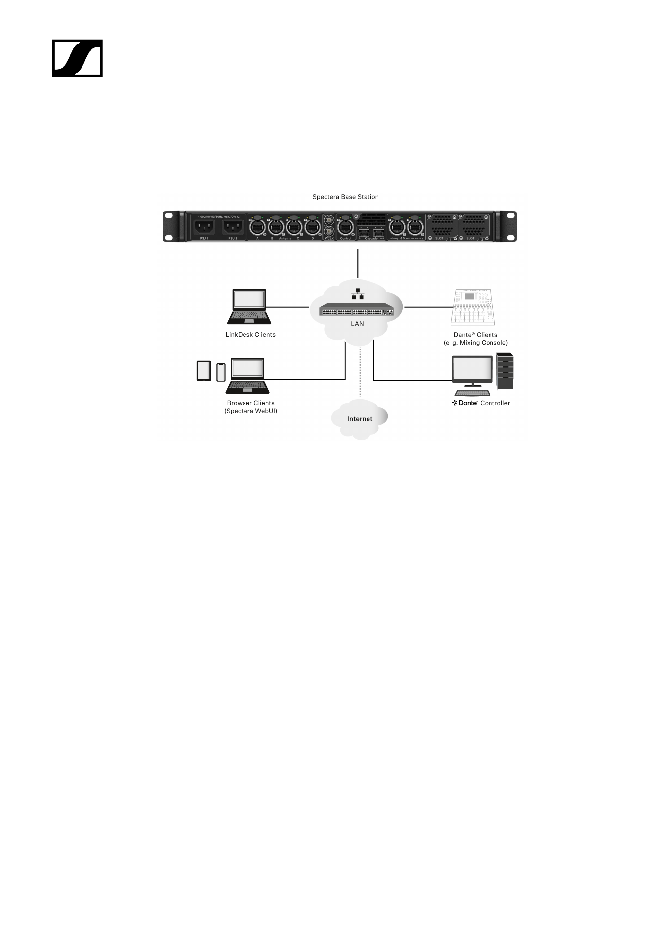
| 5 - Knowledge base
Network setups
To operate the several components of the Spectera offering they need to be integrated into
a network setup, either existing or new. Following figure shows a general overview of the
network setup and their participants.
Spectera Base Station
This Sennheiser device has 3 network interfaces. One interface dedicated for control data
and two interfaces for audio data (specifically Dante®). There is a primary and a secondary
interface for redundancy of the audio transmission.
Sennheiser LinkDesk client
This client can be any host computer (PC or Mac), with the LinkDesk software application
installed.
Browser Client (Spectera WebUI)
This client can be any host computer (PC, Mac, Tablet, Smartphone), with a supported web
browser installed, accessing the Spectera WebUI.
Dante® client
This can be any device with a Dante® network interface installed. This ranges from Virtual
Dante® Soundcards installed on a host computer up to dedicated devices like a Mixing
Console.
137

| 5 - Knowledge base
Dante® Controller
This is typically host computer (PC or Mac), with the Dante® Controller software application
installed. This application configures and controls all the Dante® devices and audio streams
inside the network.
LAN with network switches and router
This can be any network switch for routing the network communication inside the Local Area
Network (LAN) and any network router providing the gateway to other networks and to the
Internet.
Spectera Base Station - network configuration
Depending on the desired network address configuration all network interface (Control and
both Dante®) can be operated in following IP Modes with IPv4 only:
• Fixed/Static IP
• Auto IP (DHCP or Zeroconf)
Additionally it can be configured if mDNS/DNS-SD information shall be published by the
device or not.
Dante® restrictions
• It is not possible to deactivate the Dante® functionality for the both Dante®
ports.
• Dante® ports are shutdown when the device is in standby mode.
• Network configuration of Dante® ports can only be done via Dante®
Controller software application.
• By default the Dante® ports are configured to Auto IP. If Fixed/Static IPs
have been configured and the device cannot be reached anymore, the IP
Mode can only be reset to Auto IP by a Factory Reset of the device.
• The Dante primary and secondary networks must not be directly
connected to each other (network loop). Make sure you always connect
the Base Station Dante network ports to two different networks that do
not run via a common switch.
Shared Network Mode
In Shared Network Mode both networks for Control and Dante® are using the same physical
network infrastructure.
• Configure both Control and Dante® networks over one switch / router.
• Use two different IPs to address the Control network and the Dante® network
separately.
138
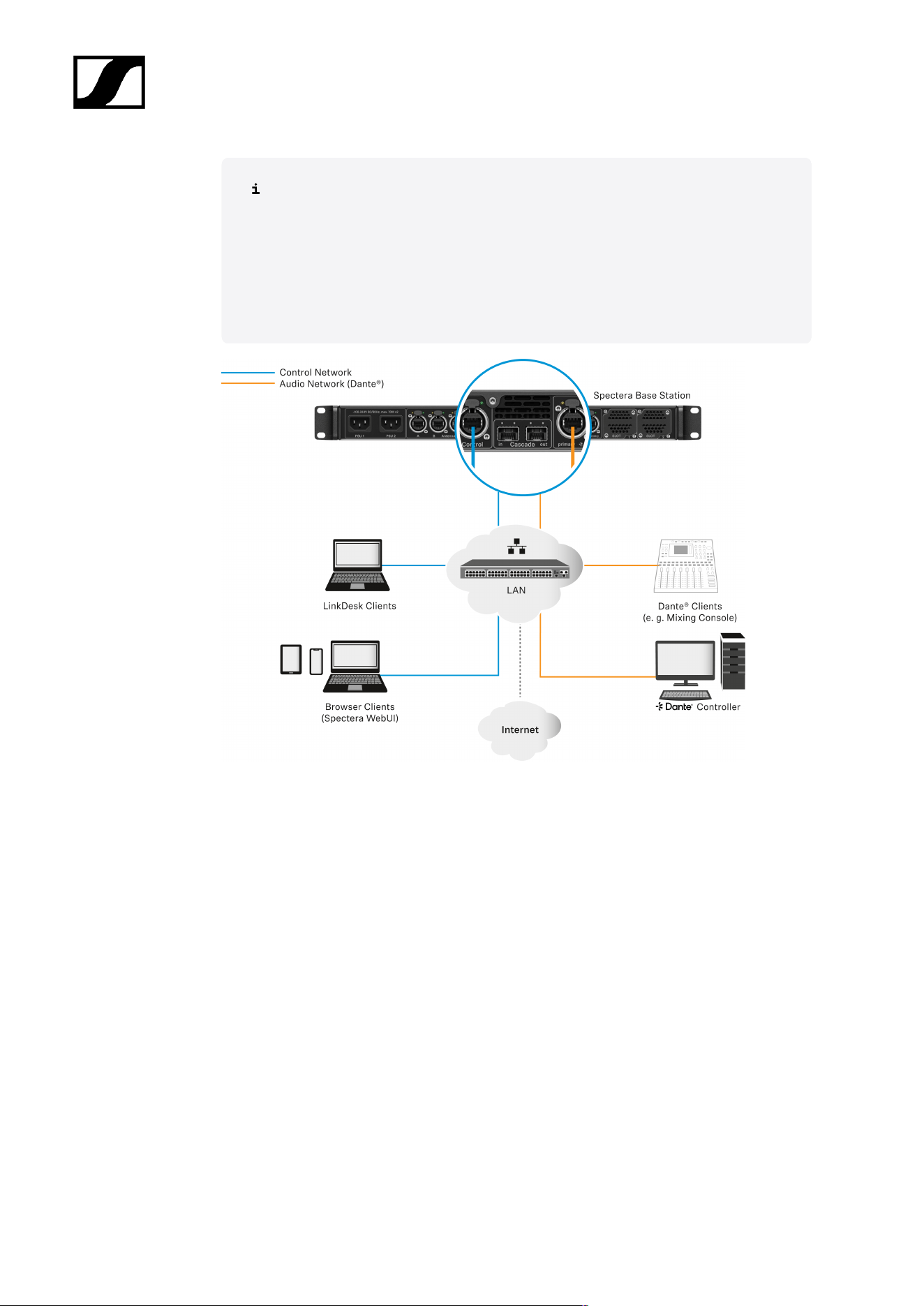
| 5 - Knowledge base
The Spectera Base Station can not be configured to use VLAN tagging (IEEE
802.1Q) at its network ports. Still it is possible to use network switches that
support VLANs to separate the Control and Dante® traffic within the same
physical network. Please make sure that the switch is configured to forward
untagged traffic from both networks to the respective ports of the Base Station.
Additionally, make sure that the switch is configured to forward multicast traffic
for the Dante® network.
Split Network Mode
In Split Network Mode both networks for Control and Dante® are using different physical
network infrastructure.
• Configure both Control and Dante® networks over two different switches / routers.
• Use two different IPs to address the Control network and the Dante® network
separately.
139
| 5 - Knowledge base
140
| 5 - Knowledge base
Ports, protocols and services
Spectera Base Station
In order to use the Spectera Base Station device in a network, certain ports must be
enabled (especially for the organization/enterprise firewall) for communication between
software and devices.
If necessary, please contact the local administrator to configure the required
ports.
Ports - Base Station Control Network Interface
Address Port Protocol Type Service Usage
Requests from device to ...
Sennheiser
License Server
address
1
80 HTTPS
(TCP)
Unicast Sennheiser
License Server
Activation of devices
ANY address of
time server (see
list of NTP time
server pools)
123 NTP Unicast NTP Time Server Synchronize system
time
224.0.0.251 5353 mDNS
(UDP)
Multicast mDNS, DNS-SD (optional - if desired)
Device/Service
Discovery
Requests to device from ...
ANY IP of SSCv2
client
443 HTTPS
(TCP)
Unicast SSCv2 - Spectera
Base Station API
Monitor+Control
communication from
clients
1
my.nalpeiron.com
NTP servers
To correctly operate with licenses and certificates, the Spectera Base Station needs a correct
system time. The device will use the well-established NTP mechanism from the IP protocol
stack to synchronize clock between a time server in a network and the client inside the
device.
Currently for an IT administrator or system integrator it is not possible to manually configure
a dedicated NTP server to be used by the Spectera Base Station. Being able to configure a
dedicated NTP server manually is a planned feature for an upcoming release.
141

| 5 - Knowledge base
The device behaves the following way:
• If a time server configuration has been provided via DHCP or manually, it tries to
connect and sync to that time server first.
• Otherwise the device is trying to access any server of following list of time server
pools worldwide publicly available.
An IT administrator has to assure to provide Internet access to at least one of the
server pools and to provide DNS settings via DHCP to the device.
List of NTP time server pools:
• pool.ntp.org
• time.nist.gov
• time.aws.com
• time.cloudflare.com
Ports - Base Station Dante® Network Interfaces
Spectera Base Station requires several ports to be opened for both Dante® Network
Interfaces to operate properly. For the list of ports and more detailed information, please refer
directly to the Dante® website: Audinate FAQ - Networks and Switches.
142
| 5 - Knowledge base
Spectera WebUI
In order to use the Spectera WebUI, certain ports must be enabled (especially for the
organization/enterprise firewall) for communication between software and devices.
If necessary, please contact the local administrator to configure the required
ports.
Port requirements
Address Port Protocol Type Service Usage
Requests from host to ...
ANY IP of a Base
Station
443 HTTPS
(TCP)
Unicast SSCv2 - Spectera
Base Station API
Monitor+Control
communication to
devices
Sennheiser
User Insights
addresses
1
443 HTTPS
(TCP)
Unicast Sennheiser User
Insights
Analytics of usage and
operational data
1
sennheiseruserinsights.matomo.cloud
cdn.matomo.cloud
143
| 5 - Knowledge base
Sennheiser LinkDesk
In order to use the Sennheiser LinkDesk software, certain ports must be enabled (especially
for the organization/enterprise firewall) for communication between software and devices.
If necessary, please contact the local administrator to configure the required
ports.
Port requirements
Address Port Protocol Type Service Usage
Host Internal
LOCALHOST 54352 HTTPS
(TCP)
Unicast LinkDesk
backend
Internal backend
communication
Requests from host to ...
ANY IP of a Base
Station
443 HTTPS
(TCP)
Unicast SSCv2 -
Spectera Base
Station API
Monitor+Control
communication to
devices
Sennheiser CIAM
addresses
1
443 HTTPS
(TCP)
Unicast Sennheiser
CIAM
Sennheiser account
Sign-in/Log-in
Sennheiser
User Insights
addresses
2
443 HTTPS
(TCP)
Unicast Sennheiser User
Insights
Analytics of usage and
operational data
Requests to host from ...
224.0.0.251 5353 mDNS
(UDP)
Multic
ast
mDNS, DNS-SD (optional - if desired)
Device/service
discovery
1
accounts-pro-emea.sennheiser-cloud.com
b2c-config.sennheisercloud.com
2
sennheiseruserinsights.matomo.cloud
cdn.matomo.cloud
144
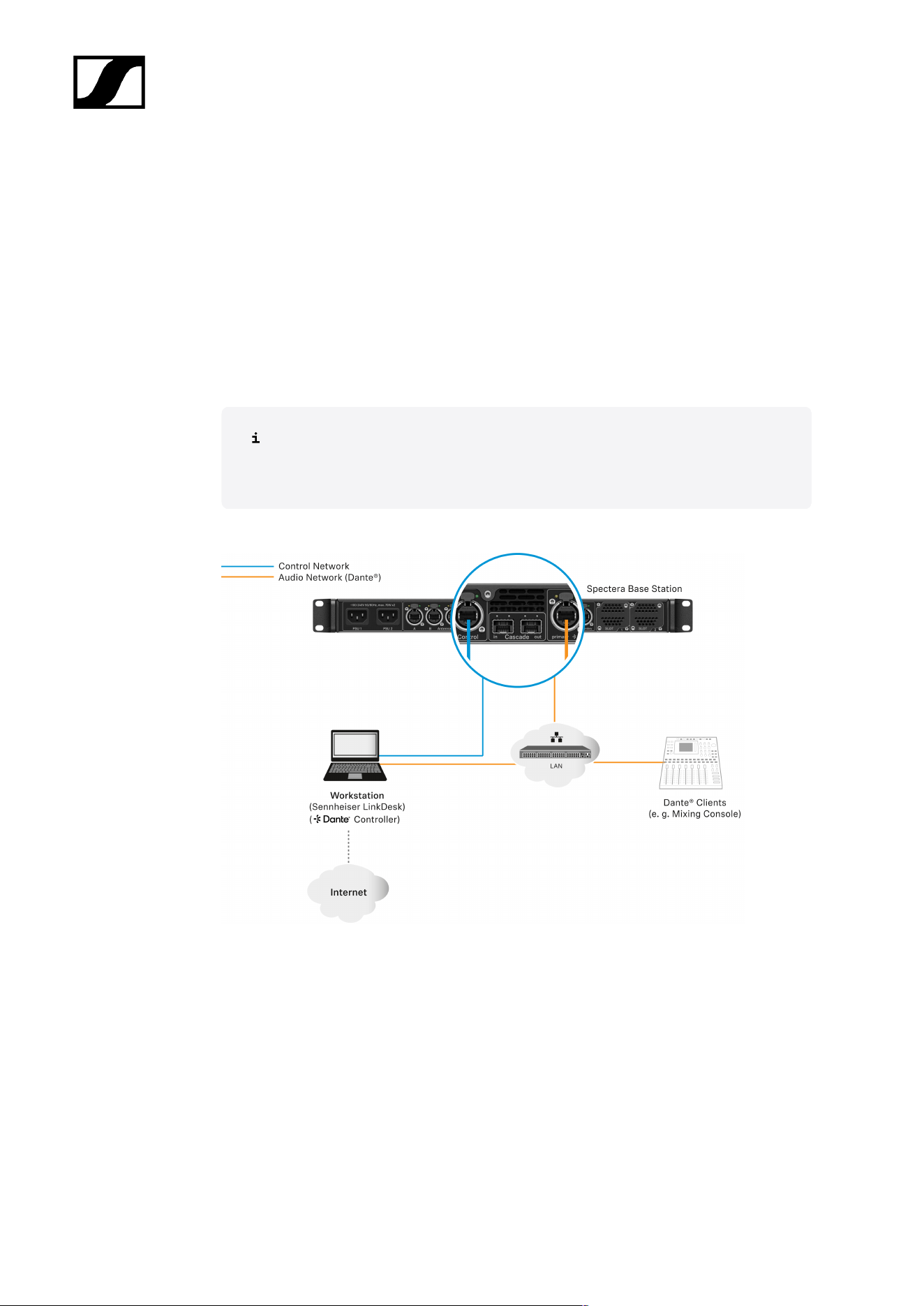
| 5 - Knowledge base
Best practice
Sharing Internet connection in small network setups
It is possible to operate the Spectera offering without dedicated router networks e.g. in
really small setups, but we do recommend to always use some kind of home network router
for trouble-free usage.
Especially for providing Internet access to Spectera Base Station it is possible to use the
builtin functionality of Windows and MacOS for Internet Connection Sharing.
For enterprise networks we DO NOT RECOMMEND the usage of Internet
Connection Sharing. Most of the times it is even prohibited by enterprise IT policy
to use such service.
The network setup might look like this:
Inside this setup one workstation is used for all client software applications (Sennheiser
LinkDesk, Spectera WebUI, Dante® Controller). Either two separated wired network interface
are used for control and audio (Dante®) or one interface gets shared. Please be aware that
in such setups (typically) no DHCP service is activated. Use either manual IP settings or
ZeroConf configuration.
For Internet Connection Sharing typically an existing network connection (Wi-Fi or Ethernet)
with Internet access gets shared with another selected network interface of the host.
145
| 5 - Knowledge base
In order to share your Internet connection on Windows:
Connect your client device to your host PC using an Ethernet cable. If either device
doesn’t have a free Ethernet port, use a USB-to-Ethernet adapter.
Go to the Network Connections menu. The easiest way to get there is by searching
for “Network Connections” in the Windows Search box.
Right-click on the network adapter connected to the Internet (for example, Wi-Fi or
modem), and then select Properties.
Toggle Allow other network users to connect to ON from the Sharing tab and select
the relevant Ethernet port from the pull-down menu.
Note that, if you have VPN software installed, you may see a lot of virtual
Ethernet ports on your list and you’ll need to pick the real one.
After you click OK, Internet should flow to your client device over its Ethernet
port. For more details on sharing an Internet connection please refer to the Microsoft
Support page.
In order to share your Internet connection on MacOS:
On your Mac, choose Apple menu > System Settings.
Click on General in the sidebar and then on Sharing (you may need to scroll down).
Turn on Internet Sharing and click on Configure.
Click the Share your connection from pop-up menu.
Choose the Internet connection you want to share ((For example, if you’re connected
to the Internet over Wi-Fi, choose Wi-Fi).
Under To devices using, turn on the port other devices can use to access the shared
internet connection. (For example, if you want to share your Internet connection over
Ethernet, select Ethernet).
If you’re sharing to devices using Wi-Fi, configure the Internet-sharing
network, then click OK.
Click on Done.
For more details on sharing an Internet connection please refer to the
Apple Support page.
Your Internet connection will be shared on MacOS/Windows.
146

| 5 - Knowledge base
Security guide
This security guide provides essential information and best practices for IT administrators,
system integrators, and event technicians to ensure robust security measures are
implemented effectively.
Professional audio systems, extensively deployed in environments such as broadcasting,
live events, and corporate settings, are increasingly integrated into enterprise networks —
making them susceptible to threats like unauthorized access, data interception, and signal
interference. To ensure secure deployment and system integrity, Sennheiser enforces the
highest security standards across all products, supported by robust protective measures and
comprehensive management practices.
• Security Principles and System Design:
Sennheiser embeds security from product development through regular risk
assessments and secure configurations, following a “security by design” approach.
Compliance with international standards ensures consistent protection and proactive
threat mitigation.
• Communication Security and Encryption:
Industry-standard encryption protocols like AES-256 and TLS protect audio and
control data from interception and unauthorized access. Secure methods such as
HTTPS and REST APIs are used for networked and third-party integrations.
• Authentication and Access Control:
Role-based authentication and device claiming validate users and devices before
granting access. b credentials and regular updates maintain system integrity and
prevent unauthorized access.
• Network Configuration and Interfaces:
Enable only essential ports, segment networks, and apply firewall rules for secure
operation. Proper configuration of protocols like Dante®, mDNS, and Bluetooth® is
critical for a robust network infrastructure.
This guide provides comprehensive measures to protect professional audio systems from
threats through secure design, encryption, authentication, and best practices throughout the
system lifecycle.
Key product security features
Key security features of Spectera devices and software tools are detailed, emphasizing best
practices for IT administrators to ensure secure communication and data protection.
Spectera devices (Base Station, DAD, and Mobile Devices (SEK)) and software tools such
as Spectera Base Station WebUI and Sennheiser LinkDesk support enhanced security
147

| 5 - Knowledge base
measures, ensuring both a secure connection between devices via radio and secure data
transfer over the network. It offers the following security features:
• AES-256 Link Encryption:
The AES-256 Link Encryption protects audio and control communication between
devices.
• Control Protocol Encryption:
The WebUI is always using encrypted HTTPS communication. The SSCv2 protocol
secures the communication between devices and software tools via HTTPS.
• Device Claiming & Authentication:
The Device Claiming & Authentication feature ensures authorized control access
using passwords.
• Dante® Media Encryption:
The Dante® Media Encryption is an optional channel encryption for Dante networks
AES-256 Link Encryption
All wireless communication between the Spectera devices will be protected with AES-256,
a top-tier encryption standard designed to safeguard sensitive data.
Link Encryption includes the following interfaces:
• The connection between the Base Station and Mobile Devices for audio transmission.
• The connection between the Base Station and Mobile Devices for device setting
synchronization.
The AES-256 Link Encryption is always enabled and can not be disabled.
148

| 5 - Knowledge base
Control Protocol Encryption
All control communication over the network to the Base Station is encrypted and
authenticated.
It offers end-to-end security, utilizing HTTPS (TLS 1.3). Communication to the Sennheiser
license server is encrypted on application level.
The Protocol Encryption is always enabled and can not be disabled.
149

| 5 - Knowledge base
Device Claiming & Authentication
Device claiming and authentication enhance security by requiring password protection for
device access and ensuring only authorized users can modify settings through encrypted
connections.
The device access via network control API and WebUI of Spectera Base Station and via
Sennheiser LinkDesk is password protected, to avoid configuring the device by unauthorized
actors inside the network.
The Device Authentication is always enabled and can not be disabled.
Benefits of device claiming
• Device Claiming Feature:
Device claiming is a feature of the Sennheiser LinkDesk and Spectera Base Station
WebUI that allows the user to claim ownership of their Sennheiser devices, providing
an extra layer of security and control.
• Device Assignment:
It allows assigning a device to one or more remote installations, which prevents any
unauthenticated device control within the network.
• Initial Configuration:
As part of the initial configuration, users claim a device by configuring a mandatory
device password.
• Usability:
Within an installation, multiple software applications can be used simultaneously with
this device password for optimal usability
• Security Measures:
Once a device is claimed, its settings can only be viewed and modified via an
encrypted connection, which requires entry of the configuration password.
150

| 5 - Knowledge base
Dante® Media Encryption (available as of Spectera Dante®
firmware Brooklyn3 version 1.1.0)
Dante® Media Encryption extends the security benefits of using Dante® on your network by
concealing the media content during transmission between devices.
Dante® utilizes the Advanced Encryption Standard (AES) with a 256-bit key to provide
industry-leading media protection.
Concealing the contents of media packets prevents malicious or unauthorized users
eavesdropping or interfering with Dante media traffic.
By default, Dante Media Encryption is disabled, since encryption can only be
configured by using the Dante Director application. Please refer to the Audinate
documentation for detailed information on Dante® encryption, on how to enable
and configure encryption and to update the Dante® firmware:
• Dante Media Encryption: Audinate/Media Encryption
• Updating Dante® firmware: Dante Updater
151

| 5 - Knowledge base
How to use the security features
The following section explains how you can use the various security features both via the
device itself and via supported software applications.
Certificates
Spectera Base Station is using a self-signed certificate for network communication.
The certificate is generated in factory and will be renewed with every factory reset.
Currently it is not possible to replace the certificate with a CA-signed certificate.
When accessing the Spectera WebUI with a browser for the first time you will get a security
warning informing about an unknown certificate. The security warning depends on the
browser you are using. Depending on your browser, click on Advanced or Show Details
(Safari) and then on:
• Microsoft Edge: Continue to localhost (unsafe)
• Google Chrome: Proceed to localhost (unsafe)
• Firefox: Accept the Risk and Continue
• Apple Safari: [...] visit this Website > Visit Website
• or similar (other browsers)
In order to prevent man-in-the-middle (MITM) attacks, Sennheiser LinkDesk has some built-
in security measures. Because of these measures, you might receive a certificate mismatch
warning while working with a Base Station. In some cases, these can occur even though
there is actually no security issue. These are:
• The Base Station has been factory reset since the last connect. In this case you can
safely confirm the connection and proceed when encountering the mismatch warning.
• A different Base Station has been connected via the same IP address. In this case
please verify if the IP Address you are using is indeed the correct IP Address of the
intended Base Station.
152

| 5 - Knowledge base
Device authentication
The devices access via network is password protected and the device must be claimed in the
control software before use.
You can claim the Base Station via:
• LinkDesk (see Claiming single device (LinkDesk)) or
• WebUI (see Claiming single device (WebUI)).
Please note that the new password must meet the following requirements:
• At least ten characters
• At least one lowercase letter
• At least one uppercase letter
• At least one number
• At least one special character: !#$%&()*+,-./:;<=>?@[]^_{|}~
• Maximum length: 64 characters
153
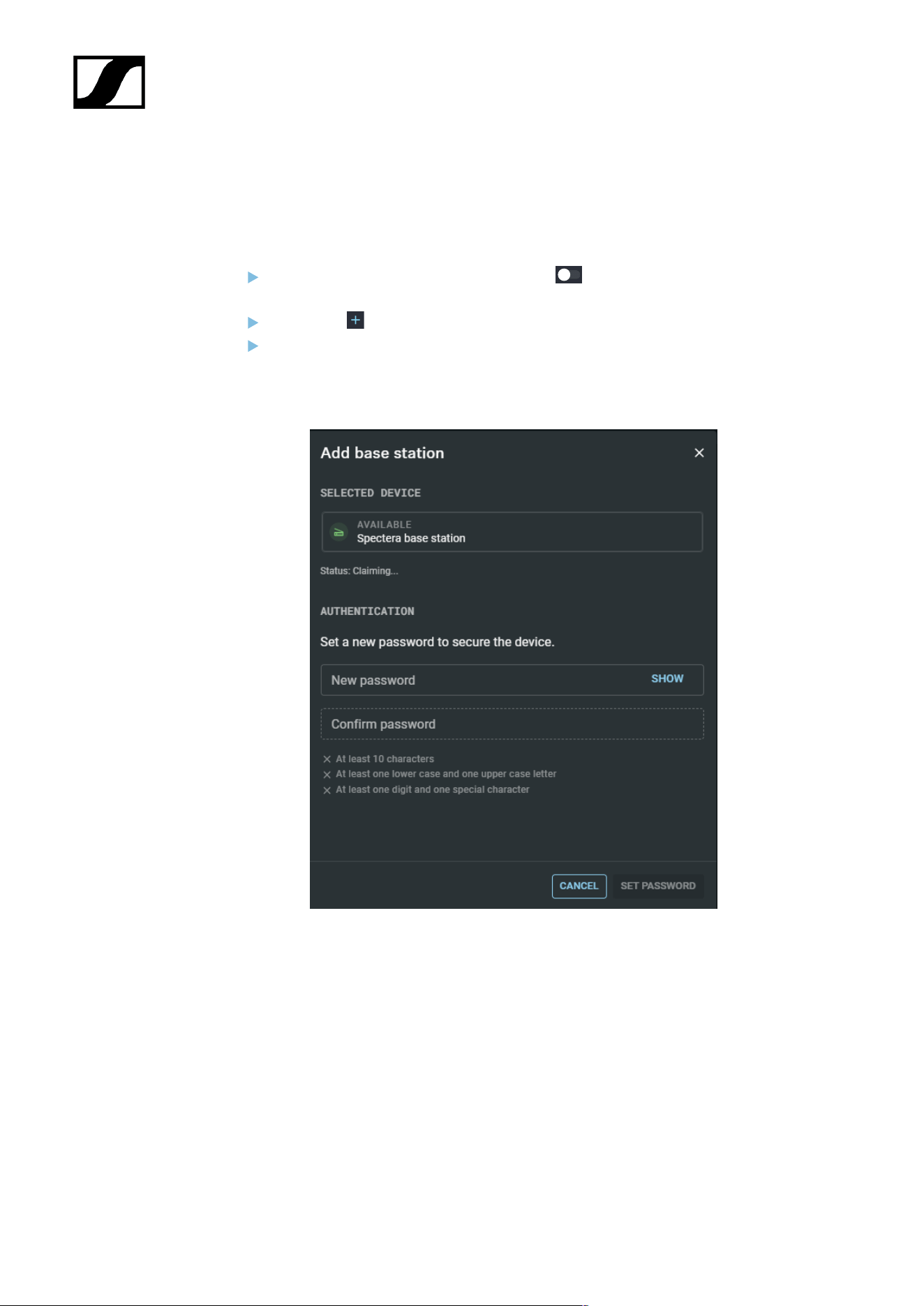
| 5 - Knowledge base
Claiming single device (LinkDesk)
Instructions for claiming a single device in Sennheiser LinkDesk.
To claim your Base Station:
In your production card, activate the function DEVICE SYNCHRONIZATION on
the left-hand side of the top bar.
Click on the symbol in the BASE STATIONS bar on the right.
Enter the correct IP address of the Base Station and click on Search.
• If the device is in a factory default state and the original password is still
assigned, it will be automatically detected and applied. Next, a new password
has to be set:
• If the device was previously claimed by another Sennheiser LinkDesk or
Spectera WebUI instance, the previously set password must be entered:
154
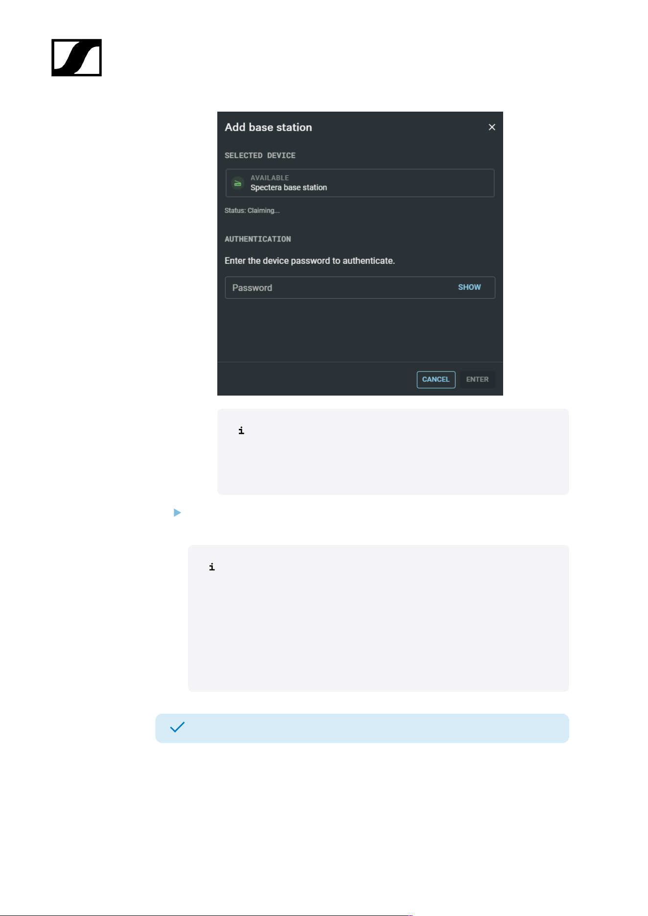
| 5 - Knowledge base
If you cannot remember the previously set password, please
perform a factory reset of the device. After the reset, the default
password for Spectera will be automatically applied by the
software.
Set a new device password (if you are logging in for the first time) or enter the
password you have already assigned for authentication (if you have already logged in).
Please note that the new password must meet the following
requirements:
• At least ten characters
• At least one lowercase letter
• At least one uppercase letter
• At least one number
• At least one special character: !#$%&()*+,-./:;<=>?@[]^_{|}~
• Maximum length: 64 characters
Your Base Station has been claimed successfully.
155
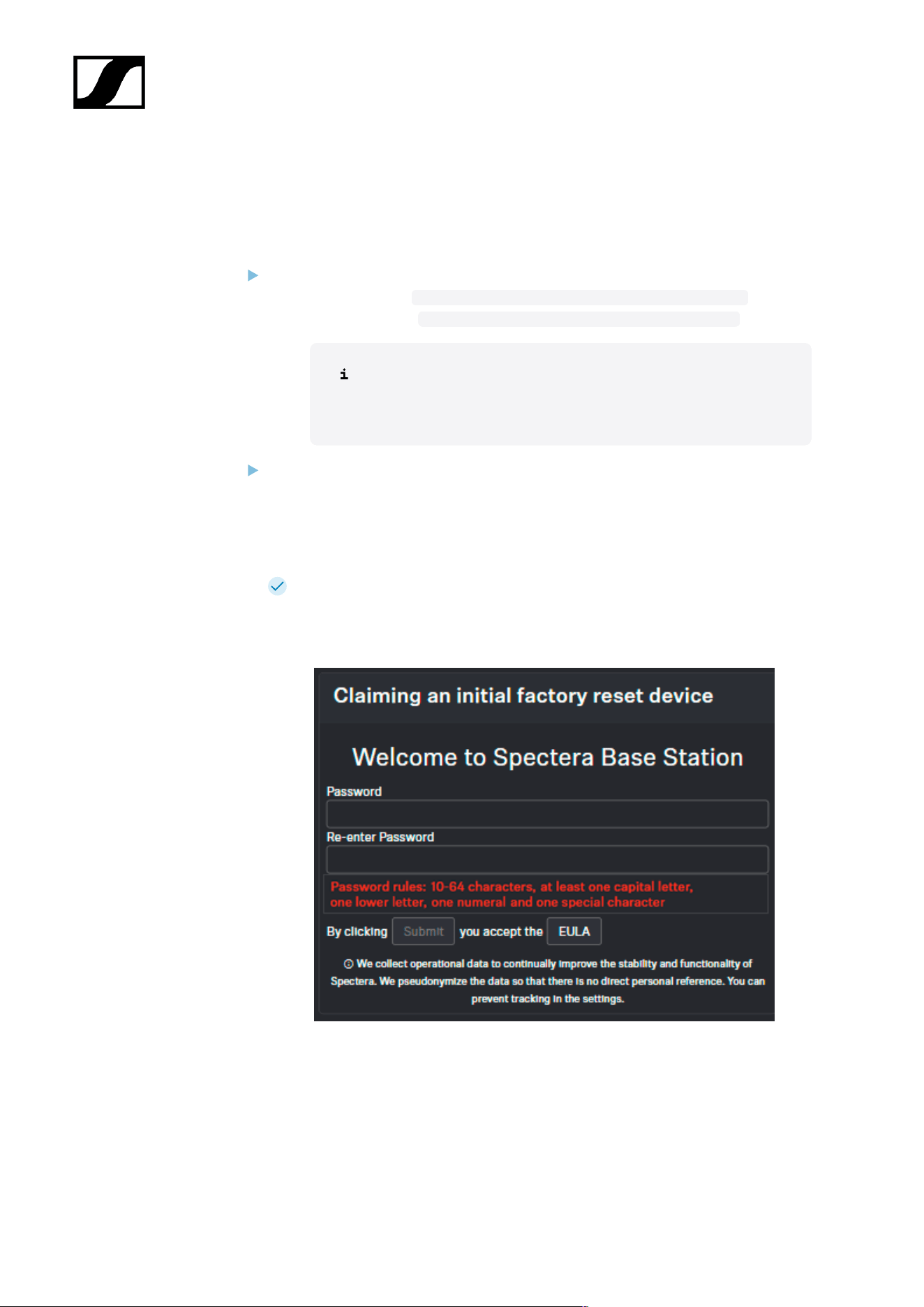
| 5 - Knowledge base
Claiming single device (WebUI)
Instructions for claiming a single device in Spectera WebUI.
To claim your Base Station:
Depending on the firmware version, enter the following URL into your browser:
• Firmware 0.8.x: https://deviceIP/specteracontrol/index.html
• Firmware ≥1.0.0: https://deviceIP/specterawebui/index.html
Since the certificate is unknown to your browser, a security
warning is displayed the first time you run the application. The
security warning depends on the browser you are using.
Depending on your browser, click on Advanced and then on:
• Continue to localhost (unsafe) (Microsoft Edge)
• Proceed to localhost (unsafe) (Google Chrome)
• Accept the Risk and Continue (Firefox)
• or similar (other browsers).
The WebUI displays the following options depending on the state of the device:
• If the device is in a factory default state and the original password is still
assigned, it will be automatically detected and applied. Next, a new password
has to be set:
• If the device was previously claimed by another Sennheiser LinkDesk or
Spectera WebUI instance, the previously set password must be entered:
156
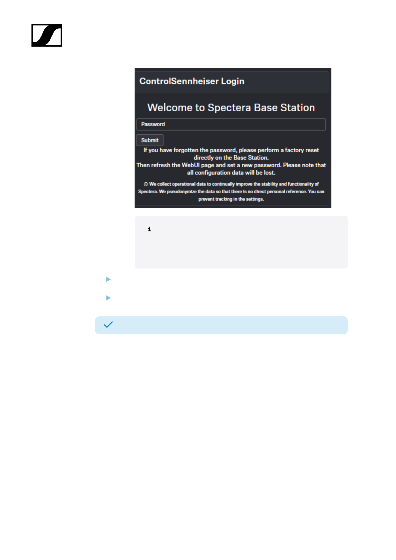
| 5 - Knowledge base
If you cannot remember the previously set password, please
perform a factory reset of the device. After the reset, the default
password for Spectera will be automatically applied by the
software.
Set a new device password (if you are logging in for the first time) or enter the
password you have already assigned for authentication (if you have already logged in).
Click on Submit.
Your Base Station has been claimed successfully.
157
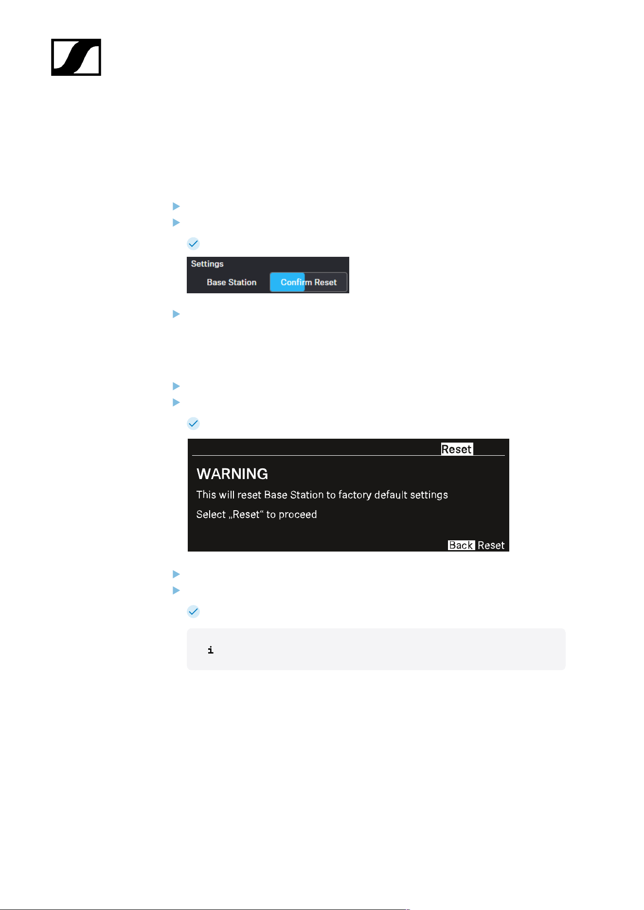
| 5 - Knowledge base
Resetting the device password (Spectera Base Station)
The device password can only be reset through a factory reset (either performed directly on
the device or remotely via WebUI):
To reset the Base Station remotely:
In the top bar, navigate to Configuration > Base Station.
Click on Settings and then on Factory Reset.
A countdown timer will be displayed (highlighted in blue).
Press Confirm Reset to confirm the factory reset.
To reset the Base Station to its factory default settings using the device:
On the Base Station, rotate the jog-dial and navigate to the menu Reset.
Press the jog-dial to enter the menu.
A warning will appear.
Rotate the jog-dial to Reset.
Press the jog-dial again.
The Base Station will be set back to factory settings and reboot.
After rebooting, check the IP address as it may have changed.
158
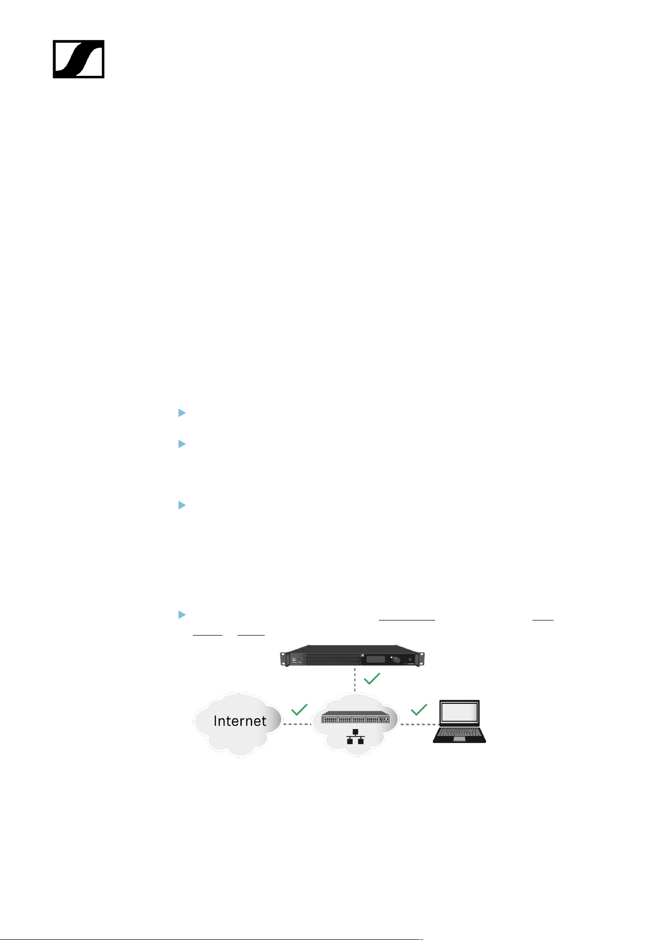
| 5 - Knowledge base
Troubleshooting
This chapter provides a systematic approach for identifying and resolving issues that may
occur during the startup or operation of Spectera.
Depending on the specific problem, click on the relevant chapter to identify possible causes
and apply potential solutions.
License activation fails
Condition
An error occurs during license activation.
Causes
The three most common causes of activation errors are as follows:
The Base Station was not connected properly and has no Internet connection (see
Solution 1: Establish a proper connection of the Base Station to the Internet).
The license server and/or NTP time server are/is unreachable due to missing port
permissions, preventing license key authorization and system clock synchronization
(see Solution 2: Open required ports for license activation and system clock
synchronization).
The license key was entered incorrectly or has already been activated and is in use
with another Base Station (see Solution 3: Check the activation code and contact
support if necessary).
Solution 1: Establish a proper connection of the Base Station to the Internet
Please connect the Base Station directly to a network with Internet access via a
switch or router.
159
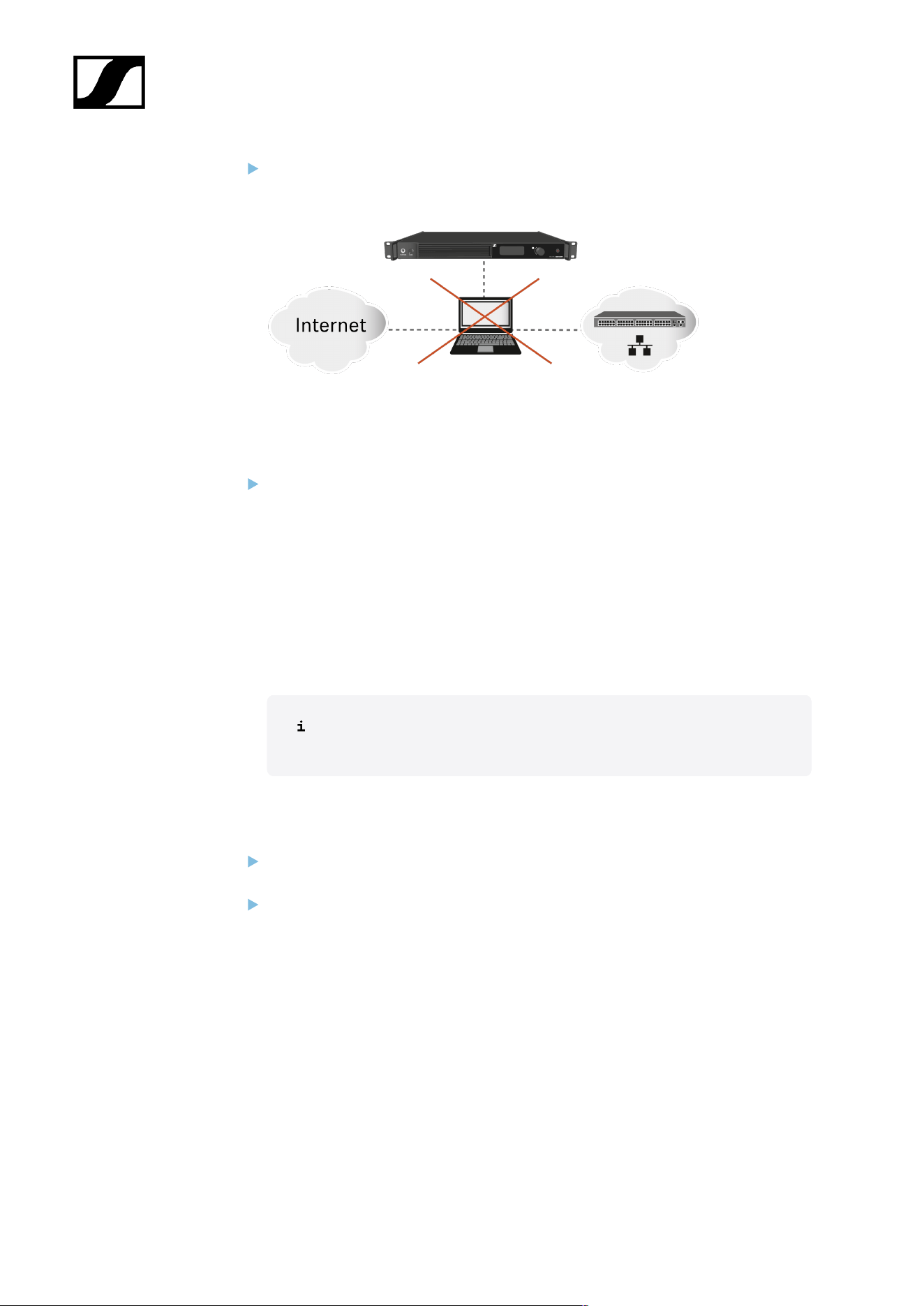
| 5 - Knowledge base
Direct connections via laptop etc. are only supported in certain network configuration
(see Sharing Internet connection in small network setups). To eliminate this issue,
please avoid a direct connection with your device for license activation.
Solution 2: Open required ports for license activation and system clock
synchronization
Please contact your IT administrator to provide Internet access to the License Server
and any NTP server by opening the required network ports and to provide DNS
settings via DHCP to the device.
Address Port Protocol Type Service Usage
my.nalpeiron.com 80 HTTPS
(TCP)
Unicast Sennheiser
License Server
Activation of
devices
ANY (see list of NTP
servers)
123 NTP Unicast NTP Time
Server
Synchronize
system time
You can find the complete overview of all ports at Ports, protocols and
services.
Solution 3: Check the activation code and contact support if necessary
Please verify that you have correctly entered the Activation Code, or check if someone
else has already used the code to activate another Base Station.
If the code has already been used for activation, please reach out to Sennheiser
Customer Support.
160

| 5 - Knowledge base
No device access via the WebUI
Condition
The device cannot be accessed via the self-hosted WebUI.
Cause
The wrong device IP or URL schema is being used in the browser.
Solution
Find out the correct IP of the Base Station (see Network).
Enter the correct IP using the correct URL schema depending on the initial firmware
version:
• Firmware ≤ 0.8.x use https://deviceIP/specteracontrol/index.html .
• Firmware ≥ 1.x.x use https://deviceIP/ .
In some cases the internet browser might have trouble showing the page. Please
use the LinkDesk software sennheiser.com/linkdesk.
161

| 5 - Knowledge base
The Base Station cannot be found
Condition
The Base Station cannot be found via LinkDesk / WebUI / Dante Manager.
Cause
The required ports for communication with the Base Station have not been made accessible.
Solution
Depending on the use case, please make the necessary ports available for the Base
Station, so that data traffic can flow unrestricted:
• Spectera Base Station
• Sennheiser LinkDesk
• Dante®
162
Spectera
6. Specifications
All technical data, system requirements and frequencies at a glance.
Spectera System
Transmission scheme
• Multicarrier, TDMA, TDD
RF channel
• Bandwidth: 6 or 8 MHz countrywise limited
• Mobiles devices: up to 128 per RF channel
• Audio links: up to 128 per RF channel
Radio frequency range
• UHF: 470 - 608 MHz, 630 - 698 MHz
• 1G4: 1350 - 1400 MHz, 1435 - 1525 MHz
• countrywise limited
Audio frequency response
• 20 Hz to 20,000 Hz (±1 dB) (Audio link modes with SeDAC and PCM audio codecs
only)
Encryption
• AES 256 CTR Mode exp. >10k years
Audio link modes
MIC/LINE Mono Max links per RF
carrier
Utilized % of RF
carrier
Audio
codec
La
tency
Range
Raw Low
Latency
Mono 8 12.5 % PCM 1.0 ms Redu
ced
Raw Mono 16 6.25 % PCM 1.6 ms Redu
ced
Live Low
Latency
Mono 8 12.5 % SeDAC 1.0 ms Exten
ded
Live Mono 16 6.25 % SeDAC 1.6 ms Exten
ded
Live Link
Density
Mono 32 3.13 % SeDAC 2.7 ms Stand
ard
163
| 6 - Specifications
MIC/LINE Mono Max links per RF
carrier
Utilized % of RF
carrier
Audio
codec
La
tency
Range
Max Range Mono 16 6.25 % OPUS 9.9
ms
Maxi
mum
Max Link
Density
Mono 128* 0.78 % OPUS 15.2
ms
Redu
ced
IEM/IFB Mono/
Stereo
Max links per RF
carrier
Utilized % of RF
carrier
Audio
codec
La
ten
cy
Range
Live Mono 16 6.25 % SeDAC 1.6
ms
Exten
ded
Live Link
Density
Mono 32 3.13 % SeDAC 2.7
ms
Stand
ard
Max Range Mono 16 6.25 % OPUS 9.9
ms
Maxi
mum
Max Link
density
Mono 128* 0.78 % OPUS 15.2
ms
Redu
ced
Live Ultra Low
Latency
Stereo 4 (8 ch) 25 % SeDAC 0.7
ms
Exten
ded
Live Low
Latency
Stereo 8 (16 ch) 12.5 % SeDAC 1.1 ms Exten
ded
Live Stereo 16 (32 ch) 6.25 % SeDAC 1.6
ms
Stand
ard
Live Link
Density
Stereo 32 (64 ch)** 3.13 % SeDAC 2.7
ms
Redu
ced
* Base Stations have 32 audio outputs, for 128 links in a single RF channel, 4 Base Stations
and firmware update with cascade port function are required (future release)
** Base Stations have 32 audio inputs, for 32 stereo links (64 ch) in a single RF channel, 2
Base Stations and firmware update with cascade port function are required (future release)
164

| 6 - Specifications
Base Station
General
RF channels
• 2
Audio inputs and outputs
• Input: up to 32 channels
• Output: up to 32 channels
• Individually selectable from digital audio interfaces
Digital audio inputs and outputs
• Dante®
• Ethernet, 1 Gbit/s
• 2× ruggedized RJ45 (Primary and Secondary)
• 32 In, 32 Out, 48 kHz or 96 kHz, 16/24/32 bit
• MADI (AES10)
• 2× Expansion Slots for MADI Card OM (optical fiber multimode) or MADI Card
BNC (separate accessories)
• 32 In, 32 Out, 48 kHz or 96 kHz, 16/24 bit
• Individual sample rate for each interface
Headphone output
• 6.3 mm jack
• 2x 50 mW at 32 Ω -40 dB THD (1%) at 1 kHz
Antenna connections
• 4 × ruggedized RJ45, PoE supply for up to 4 DAD UHF/1G4
Antenna cable
• Category 5e or higher, S/UTP (maximum 100 m)
Word clock input
• Input: BNC, 75 Ω
• Output: BNC, 75 Ω
• Sampling rates: 48 kHz, 96 kHz
Control
• Ethernet, 1 Gbit/s, ruggedized RJ45
165

| 6 - Specifications
Cascade in / out*
• 2 × SFP+ cages (to be equipped with 10 Gbit/s modules)
Power supply
• 2 x internal redundant
• 100 to 240 V AC, 50/60 Hz
Power consumption
• 70 W
Power plug
• 3-pin, protection class I as per IEC/EN 60320-1
Dimensions (H × W × D with mounting elements)
• 44 × 483 × 373 mm (1.73" x 19.02" x 14.69")
Weight
• Approx. 6.3 kg (13.89 lbs) (without accessories)
Temperature
• Operation: −10 °C to +50 °C (14 °F to 122 °F)
• Storage: −25 °C to +70 °C −13 °F to 158 °F)
Relative air humidity
• 25 % to 95 % (non-condensing)
Dripping and splashing liquids
• The product must not be exposed to dripping and splashing liquids (IP2X)
*Software update with cascade port function required (future release)
Ports - Base Station Control Network Interface
Address Port Protocol Type Service Usage
Requests from device to ...
Sennheiser
License Server
address
1
80 HTTPS
(TCP)
Unicast Sennheiser
License Server
Activation of devices
166

| 6 - Specifications
Address Port Protocol Type Service Usage
ANY address of
time server (see
list of NTP time
server pools)
123 NTP Unicast NTP Time Server Synchronize system
time
224.0.0.251 5353 mDNS
(UDP)
Multicast mDNS, DNS-SD (optional - if desired)
Device/Service
Discovery
Requests to device from ...
ANY IP of SSCv2
client
443 HTTPS
(TCP)
Unicast SSCv2 - Spectera
Base Station API
Monitor+Control
communication from
clients
1
my.nalpeiron.com
NTP time server pools
• pool.ntp.org
• time.nist.gov
• time.aws.com
• time.cloudflare.com
Ports - Base Station Dante® Network Interfaces
Spectera Base Station requires several ports to be opened for both Dante® Network
Interfaces to operate properly. For the list of ports and more detailed information, please refer
directly to the Dante® website: Audinate FAQ - Networks and Switches.
167
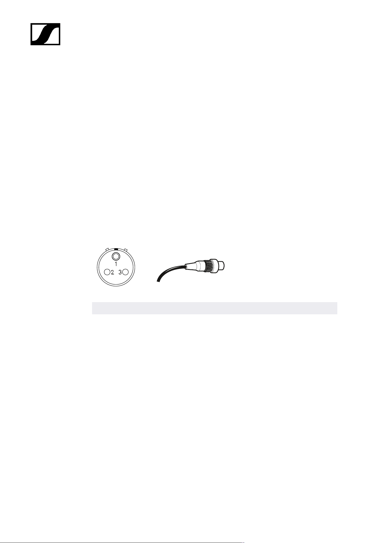
| 6 - Specifications
SEK
RF transmission power
• up to 50 mW; countrywise limited
RF channels
• 1
Headphone output
• 3.5 mm TRS jack
• 2 × 300 mW RMS (32 Ω, -40 dB THD, 1 kHz)
Microphone / Instrument / Command input
• 3-pin audio socket
Solder side
Assignment Function
Pin 1 Ground & housing
Pin 2 Line In / command*
Pin 3 Mic In & bias voltage
Housing Ground
*for auto line detection short pin 1 and 3
Power supply
• BA 70 rechargeable battery pack
Battery operating time
• up to 7 h (unidirectional microphone use)
• up to 6 h (unidirectional IEM use)
• up to 5 h (bidirectional use)
Dimensions
• approx. 83 x 62 x 21 mm (3.39" x 2.44" x 0.83") (without antenna)
168

| 6 - Specifications
Weight
• approx. 178 g (0.39 lbs) (with BA 70)
• approx. 144 g (0.32 lbs) (without BA 70)
Temperature
• Operation: −10 °C to +50 °C (14 °F to 122 °F)
• Storage: −25 °C to +70 °C −13 °F to 158 °F)
Relative air humidity
• 25 % to 95 % (non-condensing)
169

| 6 - Specifications
DAD
RF transmission power
• up to 100 mW; countrywise limited
RF channels
• 1
Base Station connection
• Ruggedized RJ45 including PoE, max. 100 m cable, CAT5e or better, 1 Gbit/s
Power consumption
• PoE class 2 (< 6.5 W)
Apex angle vertical
• vertical
• UHF: 65 °
• 1G4: 62 °
• horizontal
• UHF: 109 °
• 1G4: 93 °
Front to back ratio
• UHF: 15 dB
• 1G4: 17 dB
Gain
• UHF: 5 dB
• 1G4: 6.5 dB
Threads for tripod mounting
• Yes / Adapter 3/8" to 5/8"
Dimensions
• UHF: 349 x 292 x 39 mm (13.74" x 11.5" x 1.54")
• 1G4: 231 x 205 x 39 mm (9.09" x 8.07" x 1.54")
Weight
• UHF: 676 g (1.49 lbs)
• 1G4: 534 g (1.18 lbs)
170

| 6 - Specifications
Temperature
• Operation: −10 °C to +50 °C (14 °F to 122 °F)
• Storage: −25 °C to +70 °C −13 °F to 158 °F)
Relative air humidity
• 25 % to 95 % (non-condensing)
IP class
• IP54
171

| 6 - Specifications
CHG 70N-C charger
Power supply
• 12 V DC (single unit or cascade of up to 5 units)
• PoE IEEE 802.3af Class 0 (CAT5e or higher), single unit only
Current consumption
max. 3.5 A for a cascade of up to 5 units
Ethernet
• RJ-45 socket, IEEE802.3
• 100Base-TX (half+full duplex)
• 10Base-T (half+full duplex)
Dimensions
Approx. 200 x 104 x 116 mm
Weight
Approx. 640 g, without power supply unit
Charging slots
2
Charging capacity per slot
• BA 70 rechargeable battery or
• EW-DX SK with BA 70 or
• EW-DX SKM with BA 70
Charging voltage
4.35 V
Charging current
min. 344 mA
max. 860 mA
Full charging time
Max. 3.5 h
Temperature range
• Charging: -10 °C to +50 °C
• Storage: -20 °C to +70 °C
172

| 6 - Specifications
Relative humidity
Max. 95% (non-condensing)
173

| 6 - Specifications
BA 70 rechargeable battery
Rated capacity
1720 mAh
Nominal voltage
3.8 V
Charging voltage
max. 4.35 V
Charging time
Typically 3 h @ room temperature
Dimensions
Approx. 54 x 30 x 15
Weight
Approx. 33 g
Temperature range
• Charging: 0 °C – +55 °C (32 °F – 131 °F)
• Discharging: -10 °C to +55 °C
• Storage: -10 °C to +45 °C
Relative humidity
• Charging/discharging: 25% to 95%, non-condensing
• Storage: 30% to 70%, non-condensing
174

| 6 - Specifications
L 70 USB charger
Charging capacity
2 Sennheiser BA 70 rechargeable battery packs
Input voltage
Typically 5 V
Input current
max. 2 A
Charging voltage
nominally 4.35 V
Charging current
max. 860 mA per battery pack
Charging time
max. 3.5 h with NT 5-20 UCW power supply unit
Temperature range
• Charging: 0 °C to +55 °C
• Storage: -20 °C to +70 °C
Relative humidity
Max. 95% (non-condensing)
Dimensions
100 × 35 × 70 mm (1 3/4" x 3 7/8" x 7 3/16")
Weight
Approx. 86 g
175

| 6 - Specifications
Modular L 6000 charger
Charging capacity
• Up to 8 rechargeable batteries (BA 60, BA 61, BA 62 and BA 70) across 4
exchangeable charging modules (LM 6060, LM 6061, LM 6062 and LM 6070)
Charging times at 20° C
• BA 60
• 80%: approx. 1:15 h (approx. 4:45 h operating time)
• Full: approx. 2:30 h
• BA 61
• 80%: approx. 1:45 h (approx. 5:00 h operating time)
• Full: approx. 3:15 h
• BA 62
• 80%: approx. 1:15 h (approx. 9:30 h operating time)
• Full: approx. 2:45 h
• BA 70
• 80%: approx. 1:45 h
• Full: approx. 3:30 h
Charging temperature range
• 0 to 50 °C (32 °F to 122 °F)
Charging status display
• Multi-colored
Network
• IEEE 802.3-2002 (10/100 Mbit/s), shielded RJ-45 connection
Power supply
• AC 100 – 240 V, 50/60 Hz
Maximum power consumption
• 85 W
Minimum power consumption
• 1 W
Power plug
• 3-pin, protection class I as per IEC/EN 60320-1
176

| 6 - Specifications
Dimensions (H × W × D with mounting elements)
• 44 x 483 x 373 mm
Weight
• 5.1 kg
177

| 6 - Specifications
LM 6060 | LM 6061 | LM 6062 | LM 6070 charging
modules
Dimensions (H × W × L)
• 44 x 99 x 182 mm
Weight
• 144 g
Rechargeable battery type
• LM 6060: 2× BA 60
• LM 6061: 2× BA 61
• LM 6062: 2× BA 62
• LM 6070: 2× BA 70
178

Sennheiser electronic SE & Co. KG | Am Labor 1 | 30900 Wedemark | Germany