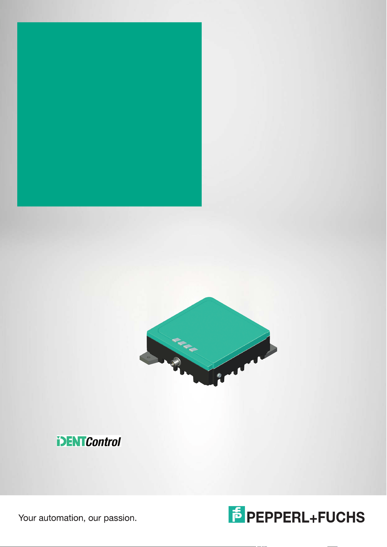
IUH1-F7xx-V1-FR*
UHF RFID Read/Write
Devices for IDENTControl
Manual

With regard to the supply of products, the current issue of the following document is applicable:
The General Terms of Delivery for Products and Services of the Electrical Industry, published
by the Central Association of the Electrical Industry (Zentralverband Elektrotechnik und Elek-
troindustrie (ZVEI) e.V.) in its most recent version as well as the supplementary clause:
"Expanded reservation of proprietorship"
Worldwide
Pepperl+Fuchs Group
Lilienthalstr. 200
68307 Mannheim
Germany
Phone: +49 621 776 - 0
E-mail: info@de.pepperl-fuchs.com
North American Headquarters
Pepperl+Fuchs Inc.
8093 Darrow Road
Twinsburg, Ohio 44087
+1 330 425-3555
United States of America
E-mail: [email protected].com
Asia Headquarters
Pepperl+Fuchs Pte. Ltd.
P+F Building
18 Ayer Rajah Crescent
Singapore 139942
Phone: +65 6779-9091
E-mail: [email protected]
https://www.pepperl-fuchs.com

IUH1-F7xx-V1-FR*
Contents
2026-08
3
1 Introduction................................................................................................................ 5
1.1 Content of this Document............................................................................. 5
1.2 Target Group, Personnel ............................................................................... 5
1.3 Intended Use .................................................................................................. 5
1.4 Symbols Used ................................................................................................ 6
1.5 Definitions ...................................................................................................... 7
1.6 Abbreviations and Terms .............................................................................. 8
2 Cybersecurity............................................................................................................. 9
3 Certificates and approvals...................................................................................... 10
3.1 General ......................................................................................................... 10
3.2 CE Marking ...................................................................................................10
3.3 FCC Compliance Statement........................................................................ 10
3.4 IC Compliance Statement ........................................................................... 11
3.5 IFT Information............................................................................................. 11
3.6 NCC-Information ..........................................................................................11
3.7 ANATEL-Information .................................................................................... 12
3.8 UL Information ............................................................................................. 12
4 UHF general.............................................................................................................. 13
4.1 RFID Frequency Bands ...............................................................................13
4.2 The Impact of Various Materials on the Detection Range........................ 13
4.3 Interference Due to Multipath Propagation............................................... 14
4.4 Polarization................................................................................................... 15
4.5 Spatial Orientation....................................................................................... 16
4.6 Memory Structure of a Tag in Accordance with EPC Gen 2 (ISO/IEC
18000-63)17
4.7 Dense Reader Mode (DRM) ........................................................................ 19
4.8 Frequency Hopping Spread Spectrum ......................................................19
4.9 Countries of Use ..........................................................................................20
5 Product Description ................................................................................................22
5.1 General ......................................................................................................... 22
5.2 Indicators and Operating Elements........................................................... 23

IUH1-F7xx-V1-FR*
Contents
2026-08
4
6 Installation................................................................................................................24
6.1 Storage and Transportation ........................................................................24
6.2 Mounting.......................................................................................................24
6.2.1 Minimum Distances .......................................................................................................... 26
6.3 Connection ...................................................................................................27
7 Commissioning and Operation...............................................................................28
7.1 General Protocol Structure.........................................................................28
7.2 Overview of Parameters ..............................................................................28
7.3 Overview of Commands ..............................................................................28
7.4 Operation via Web Interface........................................................................29
7.5 REST API.......................................................................................................30
7.6 Operation on a Control Panel .....................................................................31
7.6.1 Siemens (TIA Portal) with B40 .......................................................................................... 32
7.6.2 Rockwell (???) with B40 ................................................................................................... 33
8 Service and Maintenance........................................................................................34
9 Troubleshooting .......................................................................................................35
10 Decommissioning and Disposal ............................................................................36
11 Appendix...................................................................................................................37
11.1 ASCII table ....................................................................................................37

IUH1-F7xx-V1-FR*
Introduction
2026-08
5
1 Introduction
1.1 Content of this Document
This document contains information that you need in order to use your product throughout the
applicable stages of the product life cycle. These can include the following:
• Product identification
• Delivery, transport, and storage
• Mounting and installation
• Commissioning and operation
• Maintenance and repair
• Troubleshooting
• Dismounting
• Disposal
The documentation consists of the following parts:
• Present document
• Datasheet
Additionally, the following parts may belong to the documentation, if applicable:
• EU-type examination certificate
• EU declaration of conformity
• Attestation of conformity
• Certificates
• Control drawings
• Instruction manual
• Functional safety manual
• Cybersecurity documentation
• Other documents
1.2 Target Group, Personnel
Responsibility for planning, assembly, commissioning, operation, maintenance, and dismount-
ing lies with the plant operator.
Only appropriately trained and qualified personnel may carry out mounting, installation, com-
missioning, operation, maintenance, and dismounting of the product. The personnel must have
read and understood the instruction manual and the further documentation.
Prior to using the product make yourself familiar with it. Read the document carefully.
1.3 Intended Use
Always operate the device as described in these instructions. Only in this way, the safe function
of the device and the connected systems is guaranteed.
The protection of operating personnel and plant is only given if the device is used in accor-
dance with its intended use.
Note
For full information on the product, refer to the further documentation on the Internet at
www.pepperl-fuchs.com.
Note
For specific device information such as the year of construction, scan the QR code
on the device. As an alternative, enter the serial number in the serial number search
at www.pepperl-fuchs.com/device-information.
2026-08
6
IUH1-F7xx-V1-FR*
Introduction
1.4 Symbols Used
This document contains symbols used to identify warning messages and informative mes-
sages.
Warning messages
Warnings are provided whenever your actions may result in hazards. Always observe these
warning messages to ensure your personal safety and to prevent property damage.
Depending on the level of risk, warnings are presented in descending order as follows:
Informative messages
Action
1.
This symbol indicates a paragraph with instructions. You are prompted to perform an action or
a sequence of actions.
Danger!
This symbol indicates an imminent danger.
Non-observance will result in personal injury or death.
Warning!
This symbol indicates a possible fault or danger.
Non-observance may cause personal injury or serious property damage.
Caution!
This symbol indicates a possible fault.
Non-observance could interrupt the device and any connected systems and plants, or result in
their complete failure.
Note
This symbol brings important information to your attention.

IUH1-F7xx-V1-FR*
Introduction
2026-08
7
1.5 Definitions
The data representation format varies in the following documentation. The following formats are
used:
ASCII
Example: "A"; "B"; "1"; "2"
An ASCII character corresponds to one byte. 2
8
= 256 different characters can be represented.
Binary
Example: 1001
bin
Binary numbers are indicated by the suffix
bin
.
DECIMAL
Example: 1234
Decimal numbers are shown without any additional notation.
HEX
Example: 0x41; 0x42; 0x31; 0x32
The hexadecimal representation of a byte consists of two digits (e.g., 0x41). The section on the
left side is the higher nibble (0x4). The lower nibble is on the right side (0x1). The range of val-
ues is between 0x00 ... 0xFF.
Note
In the TIA Portal from Siemens, hexadecimal numbers are displayed as follows:
Example:
16#00 (equivalent to 0x00)
2026-08
8
IUH1-F7xx-V1-FR*
Introduction
1.6 Abbreviations and Terms
Abbreviations
Terms
AFI Application Family Identifier
CRC Cyclic Redundancy Check
EIRP Equivalent Isotopically Radiated Power
EPC Electronic Product Code
ERP Effective Radiated Power
FCC Federal Communications Commission
FHSS Frequency Hopping Spread Spectrum
IC Industry Canada
ISO International Standardisation Organisation
MDID Mask Designer Identifier
PC Protocol Control
RFID Radio Frequency Identification
PLC Programmable Logic Controller
Tag Read/write tag; tag
TID Tag Identifier
TMN Tag Model Number
UHF Ultra-High Frequency
UII Unique Item Identifier
Read/write tag Mobile data carrier containing user data and a unique number
Fixed code Unique and unchangeable number of a read/write tag
IUC Pepperl+Fuchs-specific designation of a UHF read/write tag
ISO/IEC 18000-
63
Standard for data transmission in a UHF MHz-RFID system
RFID read/write
device
RFID read/write device with integrated IDENTControl interface for contact-
less data transmission
PLC Programmable logic controller; device for controlling a machine or plant

IUH1-F7xx-V1-FR*
Cybersecurity
2026-08
9
2 Cybersecurity
The device is secure developed according to IEC 62443-4-1 for the application area
defined here.
To ensure cybersecure operation and to protect the device, implement the following measures.
Security Context
The RFID read/write device is intended for operation on an IDENTControl RFID evaluation unit
from Pepperl+Fuchs.
The Communication is realized via a proprietary, unencrypted, serial protocol.
No physical protection against unauthorized access is required.
Maintenance and Management
Check the website regularly for security advisories publications: https://www.pepperl-
fuchs.com/cybersecurity.
Report incidents to the manufacturer.
Decommissioning
Reset the device to factory setting.
The device stores certain operating data permanently.

2026-08
10
IUH1-F7xx-V1-FR*
Certificates and approvals
3 Certificates and approvals
3.1 General
This manual applies to several types and variants of the device. The applicable approvals can
be found in the relevant data sheet for your device. Further approvals are available on request.
3.2 CE Marking
This product was developed and manufactured in line with the applicable European standards
and directives.
3.3 FCC Compliance Statement
This device complies with Part 15 of the FCC Rules. Operation is subject to the following two
conditions:
1. this device may not cause harmful interference, and
2. this device must accept any interference received, including interference that may cause
undesired operation.
Attention:
Changes or modifications not expressly approved by the party responsible for compliance
could void the user's authority to operate the equipment.
To comply with FCC part 15 rules in the United States, the system must be professionally
installed to ensure compliance with the Part 15 certification. It is the responsibility of the opera-
tor and professional installer to ensure that only certified systems are deployed in the United
States. The use of the system in any other combination (such as co-located antennas transmit-
ting the same information) is expressly forbidden.
To comply with FCC RF exposure compliance requirements, the antennas used for this trans-
mitter must be installed to provide a minimum separation distance from all persons as specified
in the table below and must not be co-located or operated in conjunction with any other
antenna or transmitter.
Note
A Declaration of Conformity can be requested from the manufacturer or downloaded from
www.pepperl-fuchs.com.
Note
This equipment has been tested and found to comply with the limits for a Class A digital device,
pursuant to part 15 of the FCC Rules. These limits are designed to provide reasonable
protection against harmful interference when the equipment is operated in a commercial
environment. This equipment generates, uses, and can radiate radio frequency energy and, if
not installed and used in accordance with the instruction manual, may cause harmful
interference to radio communications. Operation of this equipment in a residential area is likely
to cause harmful interference in which case the user will be required to correct the interference
at his own expense.
Type/Design Minimum separation distance
IUH1-F7xx-V1-FR* 25 cm

IUH1-F7xx-V1-FR*
Certificates and approvals
2026-08
11
3.4 IC Compliance Statement
This device contains licence-exempt transmitter(s)/receiver(s) that comply with Innovation, Sci-
ence and Economic Development Canada’s license-exempt RSS(s). Operation is subject to
the following two conditions:
1. This device may not cause interference.
2. This device must accept any interference, including interference that may cause unde-
sired operation of the device.
L’émetteur/récepteur exempt de licence contenu dans le présent appareil est conforme aux
CNR d’Innovation, Sciences et Développement économique Canada applicables aux appar-
eils radio exempts de licence. L'exploitation est autorisée aux deux conditions suivantes:
1. L'appareil ne doit pas produire de brouillage.
2. L'appareil doit accepter tout brouillage radioélectrique subi, même si le brouillage est sus-
ceptible d'en compromettre le fonctionnement.
To comply with IC RF exposure compliance requirements, the antennas used for this transmit-
ter must be installed to provide a minimum separation distance from all persons as specified in
the table below and must not be co-located or operated in conjunction with any other antenna
or transmitter.
3.5 IFT Information
3.6 NCC-Information
The company, firm or user shall not
1. change the frequency,
2. increase the power or
3. change the features and functions of the original design of the certified low power RF
equipment without approval.
The use of low-power RF equipment shall not affect flight safety or interfere with legal commu-
nications; if interference is found, it shall be immediately discontinued and improved until there
is no interference before continued use.
The aforementioned legal communication refers to the radio communication operated in accor-
dance with the Telecommunications Control Law. Low-power RF equipment shall tolerate inter-
ference with legal communications or radioactive electrical equipment for industrial, scientific
and medical use.
Type/Design Minimum separation distance
IUH1-F7xx-V1-FR* 25 cm
This device complies with Federal Telecommunications Institute IFT standard(s). Operation is
subject to the following two conditions:
1. this device may not cause interference, and
2. this device must accept any interference, including interference that may cause undesired operation
of the device.
Este dispositivo cumple con las normas del Instituto Federal de Telecomunicaciones IFT. La
operación de este equipo está sujeta a las siguientes dos condiciones:
1. es posible que este equipo o dispositivo no cause interferencia perjudicial y
2. este equipo o dispositivo debe aceptar cualquier interferencia, incluyendo la que pueda causar su
operación no deseada.
取得審驗證明之低功率射頻器材,非經核准,公司、商號或使用者均不得擅自變
更頻率、加大功率或變更原設計之特性及功能。 低功率射頻器材之使用不得影響
飛航安全及干擾合法通信;經發現有干擾現象時,應立即停用,並改善至無干擾
時方得繼續使用。前述合法通信,指依電信管理法規定作業之無線電通信。低功
率射頻器材須忍受合法通信或工業、科學及醫療用電波輻射性電機設備之干擾。

2026-08
12
IUH1-F7xx-V1-FR*
Certificates and approvals
3.7 ANATEL-Information
This equipment is not entitled to protection against harmful interference and may not cause
interference in duly authorized systems. For more information, consult the ANATEL website
www.anatel.gov.br
Este equipamento não tem direito à proteção contra interferência prejudicial e não pode cau-
sar interferência em sistemas devidamente autorizados. Para maiores informações, consulte o
site da ANATEL – www.anatel.gov.br
3.8 UL Information
This device may be operated in altitudes up to 5000 m.
The ambient temperature range is from -25 °C ... +70 °C for operation. The Pollution degree is
2.
The maximum relative humidity is 80 % for temperatures up to 31 °C decreasing linearly to
50 % relative humidity at 40 °C.
Nominal power supply voltage is 24 V
DC
, voltage range is 18 V ... 30 V
DC
. Supply must be LEC
(Limited Energy Circuit), LPS (Limited Power Source) or CLASS 2. The Overvoltage
Category II is applied.
The degree of protection is not included in the UL approval. The degree of protection is tested
by Pepperl+Fuchs SE.
The ext. circuits intended to be connected to this unit shall be galv. separated from mains sup-
ply or hazardous live voltage by reinforced or double insulation and meet the limits of clauses
6.3 and 9.4 of UL 61010-1.
Caution!
Cable Specifications
The maximum permissible temperature of the connection cable must be at least +90 °C.
The minimum diameter of the connection cable must be 22 AWG or 0.34 mm
2
.
Connection cables with cULus / cURus approval (PVVA/7, PVVA2/8, CYJV/7, CYJV2/8) must
be used.
The rated current of the connection cable must be at least 1 A (per pin/wire).
IUH1-F7xx-V1-FR*
UHF general
2026-08
13
4 UHF general
4.1 RFID Frequency Bands
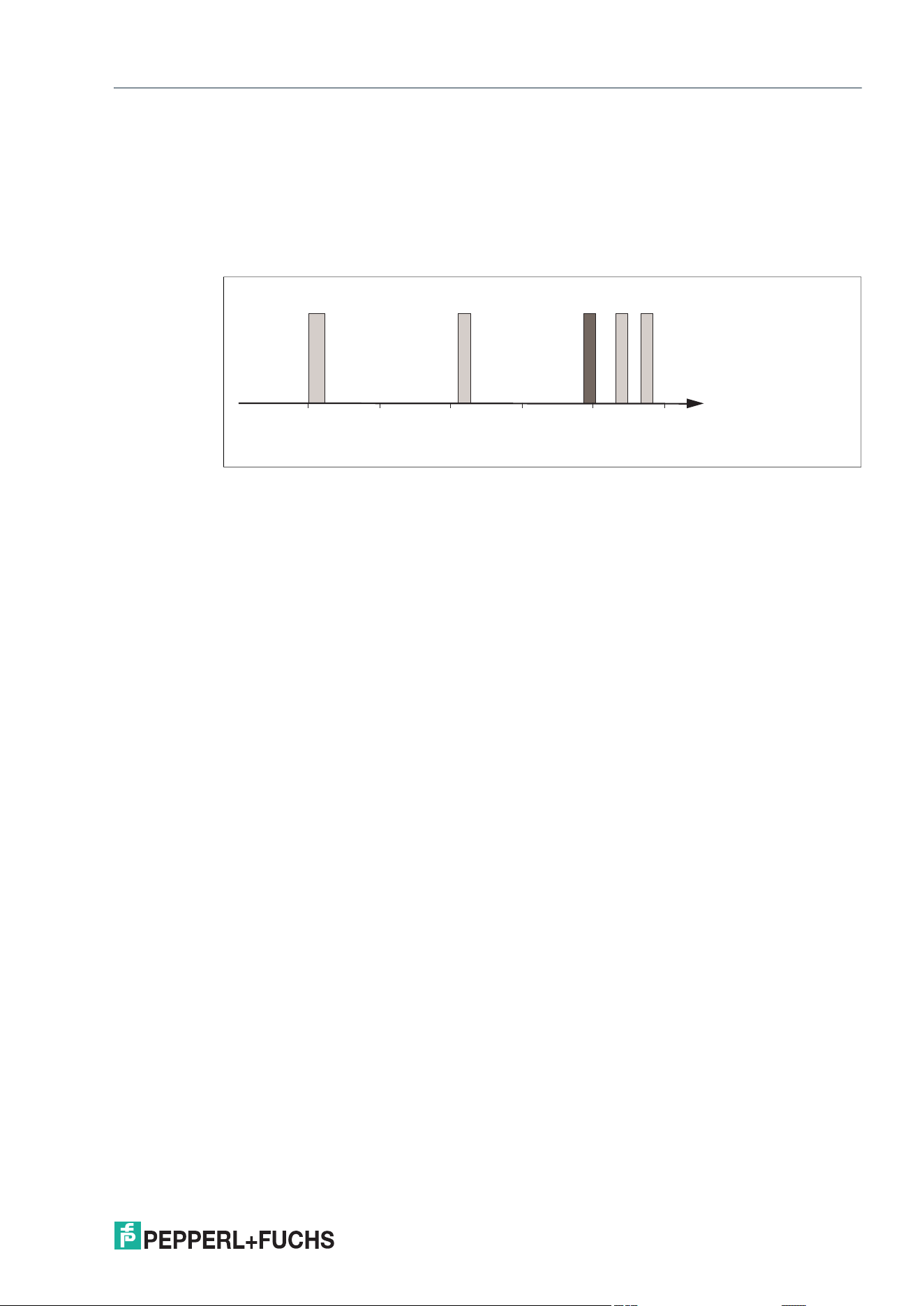
The following diagram shows the position of the different frequency bands used for RFID. The
devices described in this manual operate in the frequency range from 865 MHz ... 868 MHz,
and from 902 MHz ... 928 MHz, which is highlighted.
• 100 kHz ... 135 kHz: Low frequency (LF)
• 13.56 MHz: High frequency (HF)
• 860 kHz ... 960 MHz: Ultra-high frequency (UHF)
4.2 The Impact of Various Materials on the Detection Range
In the UHF frequency band, the properties of the environment and surface on which the tag is
mounted strongly affect the system's read/write detection range. Therefore, the UHF tags can-
not be mounted on metal without adjustments. For example, glass has a negative impact on the
detection range when used as a mounting surface. When a UHF tag is mounted on damp
materials, the detection range is worse compared to dry material.
There are tags available that are optimized for mounting on metal or on an electrically conduc-
tive surface. They can be mounted on metal without an additional spacer. Check whether the
tag used is suitable for the corresponding installation location. Information on this can be found
on the datasheet of the tag. If these tags are mounted on plastic material or non-electrically
conductive materials, the achievable sensing range can be reduced compared to mounting on
metal.
Generally speaking, the sensing range always depends on the mounting surface material. It is
therefore impossible to make a generalization about a tag's detection range. Only a statement
with restrictions is possible. The detection range achieved with the currently set parameters
must be checked at each installation point of an RFID read/write device. The transmitter radi-
ated power can be used to affect the sensing range of the RFID read/write device. The trans-
mitter radiated power must be set so that the read/write tag can be read securely at the lowest
possible power level. An increase in the transmitter radiated power can lead to unintentional
identification of nearby read/write tags. This unintentional identification of read/write tags in the
vicinity of the RFID read/write device should also be checked.
Frequency
[MhZ]
125 kHz
2,45 GHz
13,56 MHz
5,8 GHz
868/915 MHz
0,1
LF
110
HF
100 1000
UHF
10000
MW
2026-08
14
IUH1-F7xx-V1-FR*
UHF general
4.3 Interference Due to Multipath Propagation
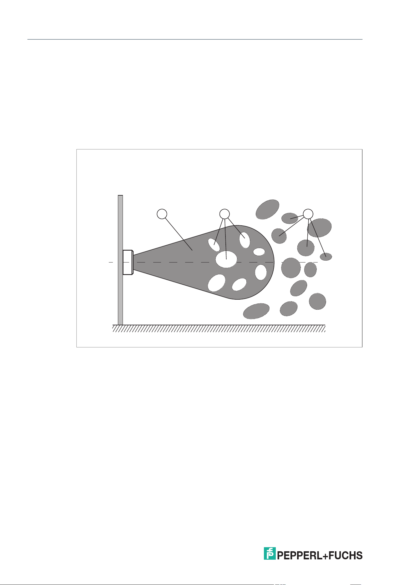
The electromagnetic waves radiated by the device do not just follow the direct route to the tag,
but are reflected off objects in the environment. This means that multiple partial waves overlap.
This overlap causes interference in the form of excessive peaks or reductions of the field
strength, leading to complete system degradation. Depending on the environment, several
reflections may occur with differing intensity. These different reflections lead to a field strength
in the sensing range that is difficult to predict. In the areas of reduction, the prevailing field
strength is weaker than the minimum detection field strength of the tag. As a result, the tag can-
not be activated for communication. Excessive peaks of the field strength may lead to
unwanted excessive detection ranges.
1. Sensing range
2. Degradation
3. Excessive detection ranges
The reflections and the resulting spatial inhomogeneity of the field strength may depend on the
frequency used. Since the tags move in the sensing range of the device, and the environment
can change, it is advisable to repeat the commands at different transmission frequencies. Dif-
ferent transmission frequencies are advisable, since the manufacturing tolerances and the
immediate environment of the tag have an effect on the tag's resonance frequency.
In the case of reduction due to interferences, the absolute value of the field strength depends
on the transmitter radiated power. It may be useful to adjust the transmitter radiated power
accordingly.
1 2 3
IUH1-F7xx-V1-FR*
UHF general
2026-08
15
4.4 Polarization
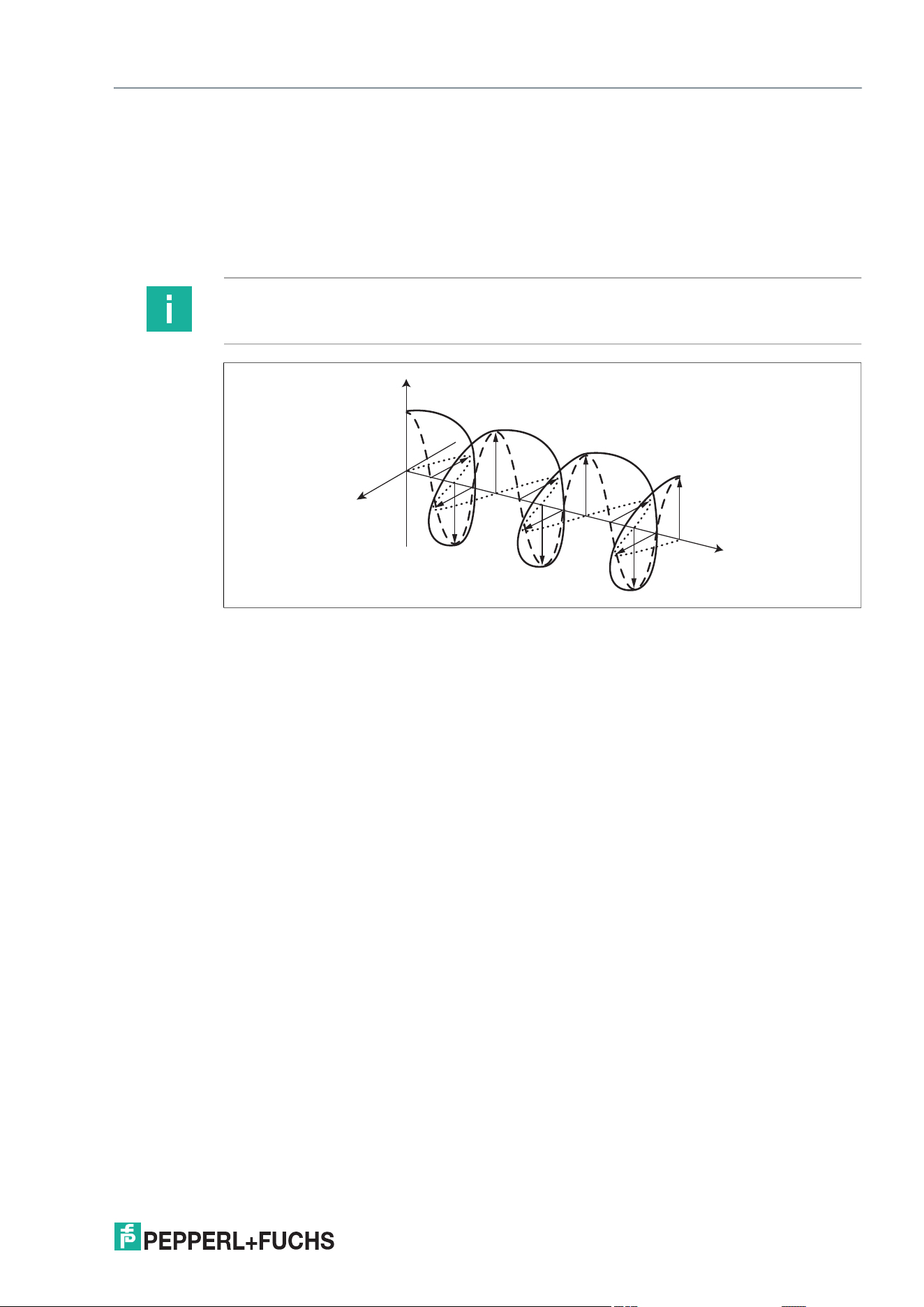
The polarization of the electromagnetic wave emitted by an antenna depends on the type of
antenna and is defined via the electromagnetic field component of the electromagnetic wave.
Polarization can be either linear or circular. In the case of an electromagnetic wave with linear
polarization, the orientation of the electric field vector is spatially constant and therefore depen-
dent on the position of the antenna. Linear polarization can usually be either vertical or horizon-
tal.
Figure 4.1
Note
The integrated antenna of the RFID read/write device has circular polarization. The polarization
of the antenna cannot be changed.
Linear polarization
• Vertical
– – – –
• Horizontal
··········
Circular polarization
• Right-handed polarization
Left-handed polarization
——–
2026-08
16
IUH1-F7xx-V1-FR*
UHF general
4.5 Spatial Orientation
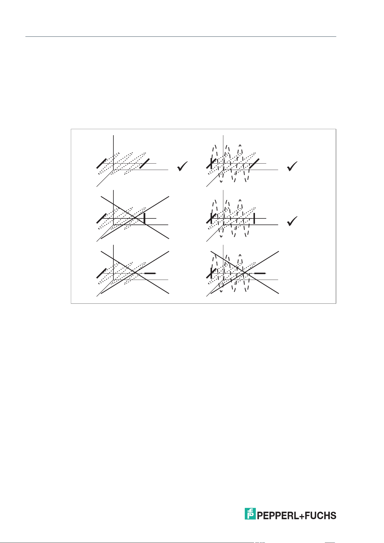
The orientation of the tag in relation to the antenna of the RFID read/write device influences the
detection range of the system. Make sure the antennae are oriented parallel to each other.
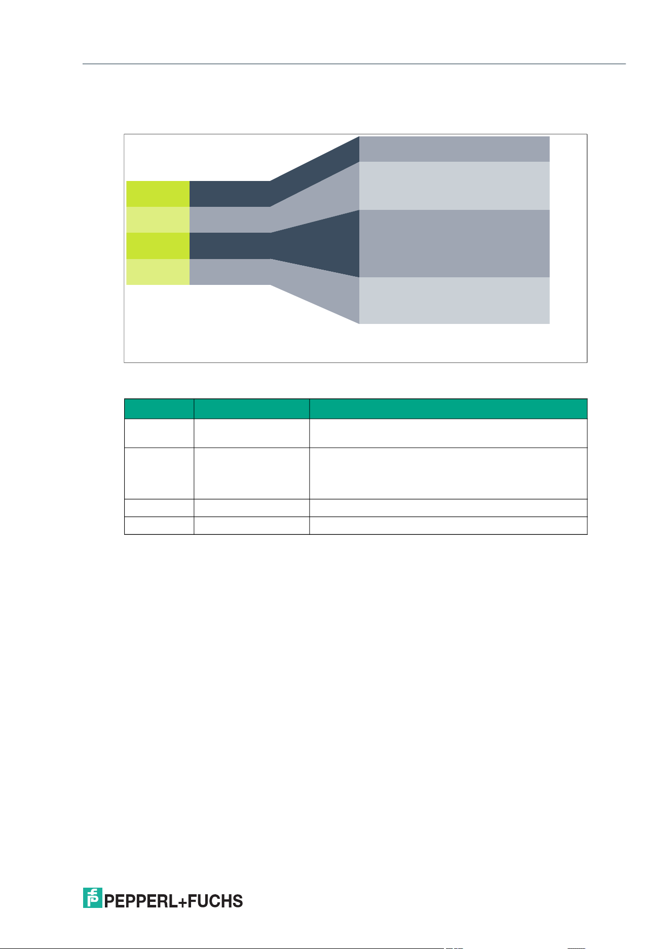
The following figure shows how the tags must be oriented with linear and circular polarization to
enable good communication between the RFID read/write device and the tag. The tag is
located on the right-hand side and the RFID read/write device is located on the left-hand side.
Linear polarization Circular polarization
Optimal tag orientation
• Good communication between the device and
tag
Poor tag orientation
• Insufficient communication between the device
and tag
IUH1-F7xx-V1-FR*
UHF general
2026-08
17
4.6 Memory Structure of a Tag in Accordance with EPC Gen 2 (ISO/IEC
18000-63)
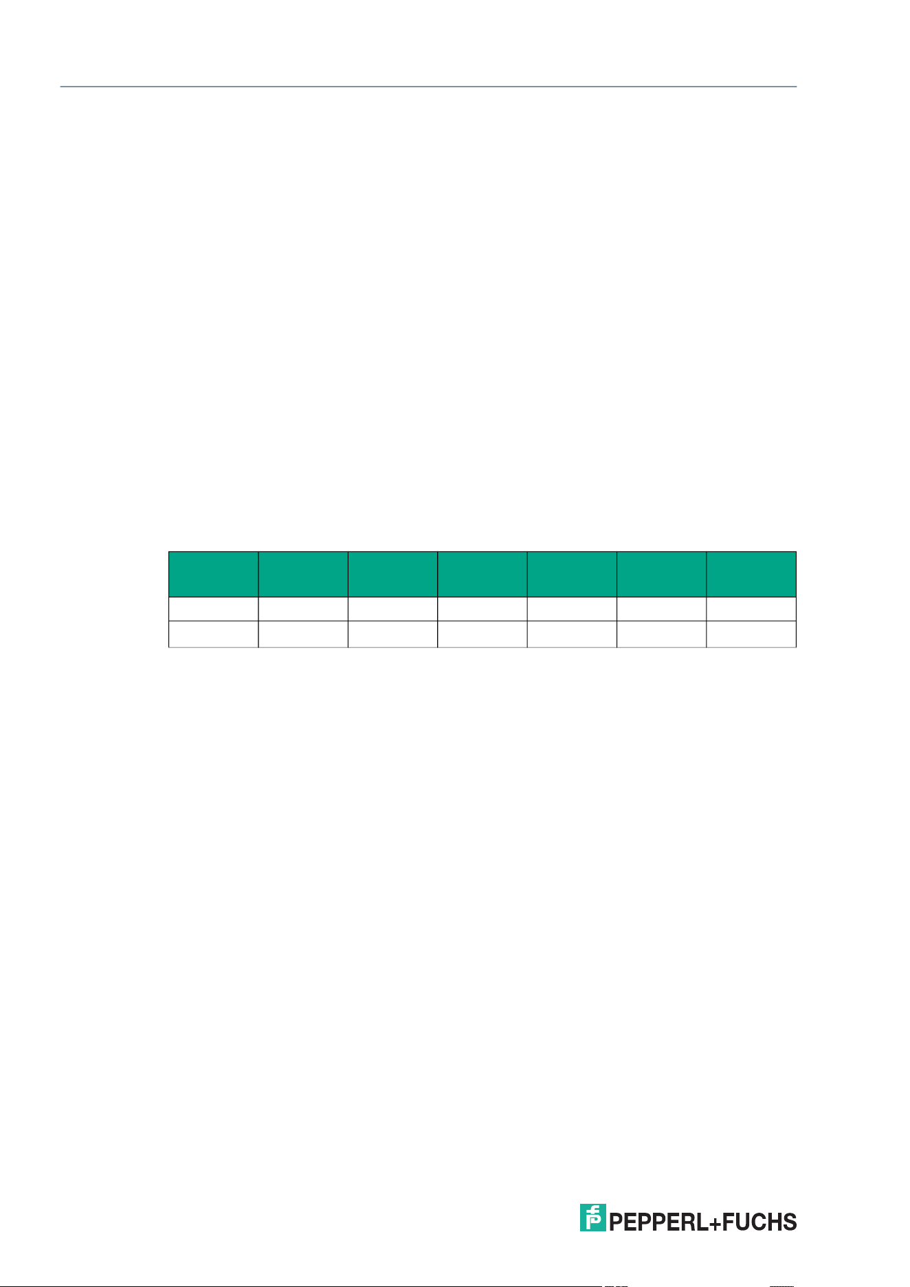
The memory module of an EPC Gen 2 (ISO/IEC 18000-63) tag is split into four segments
(banks). The main contents of these segments are:
Bank 00: Password Management
The Bank 00 segment contains the password management information. It contains the access
password and the kill password.
Bank 01: EPC/UII
The Bank 01 segment contains the EPC/UII. The segment is divided into several subsections:
Bytes 0 and 1 of the memory bank contain a checksum (CRC). This is calculated inde-
pendently by the read/write tag. This subsection can only be read.
The PC word (Protocol Control) is located in bytes 2 and 3. It contains the following information:
• Length of EPC/UII
• Application Family Identifier (AFI)
• Toggle bit to indicate whether it is an EPC or ISO standard code
• Bit to indicate whether data is stored in segment 11 (user memory)
Segment Function Length
Bank 00
Password manage-
ment
Depends on the tag type
Bank 01
Unique Item Identifier
(UII)
Electronic Product
Code (EPC)
Depends on the tag type
Bank 10 Tag ID (TID) 4 bytes (MDID, TMN) + 0 bytes, 4 bytes, or 8 bytes
Bank 11 User memory Depends on the tag type
• CRC (Cyclic Redundancy Check; checksum)
16 bits
• PC (Protocol Control; PC word)
16 bits
• EPC (Electronic Product Code) or UII (Unique
Item Identifier)
Variable length
USER
TID
UII/EPC
RESERVED
Bank 10
Bank 01
Bank 00
Bank 11
Memory
Bank
Memory
Ty p e
Memory
Blocks
User Data
TID
Manufacturer
Electronic Product Code
Protocol Control
CRC
Access Password
Kill Password
2026-08
18
IUH1-F7xx-V1-FR*
UHF general
Electronic Product Code (EPC)
The Electronic Product Code (EPC) is a unique identifier in the form of a sequence of numbers.
The number sequence has a set structure and a length of 64 bits, 80 bits, 96 bits, or longer,
depending on the EPC used. This number sequence is saved to the RFID tag, offering world-
wide unique identification of the tagged object.
The EPC system was defined by GS1 for use in inventory management. Tags with memories
for EPCs must be programmed by the user. The memory of new tags must not contain any valid
EPCs. The EPCs are managed and assigned by GS1. To obtain an EPC, please contact the
GS1 subsidiary in your country (www.gs1.com/contact).
The EPC is currently defined by GS1 in 13 different encoding schemes. SGTIN-96 (serialized
global trade item number) is given here as an example of a frequently used encoding scheme.
SGTIN-96 has a defined format and is structured as follows:
1. Header: The header specifies the EPC standard used and denotes the number sequence.
2. Filter value: Denotes the unit of the product, for example, end product, outer packaging,
pallet.
3. Partition: Denotes the point at which the following company prefix ends and the object
data begins.
4. Company prefix: Assigned sequence of numbers that identifies the producer.
5. Object class: Sequence of numbers that describes the object, e.g., item number.
The company prefix and the object class are each of variable length, but together are al-
ways 44 bits long.
6. Serial number: Sequence of numbers that identifies the item, e.g., the sequential serial
number of the item.
Bank 10: TID
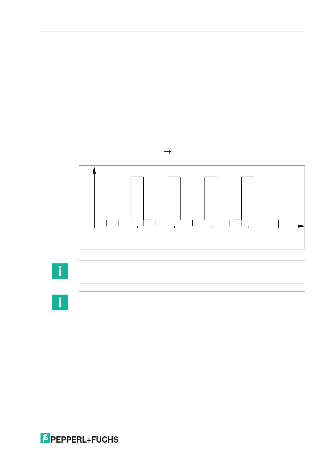
The Bank 10 segment contains the tag identifier (TID). The TID always consists of a "Short Tag
Identification" (short TID) and optionally consists of an "Extended Tag Identification" (XTID).
The short TID has a length of 4 bytes (32 bits) and is structured as follows:
If the bit for the extended tag identification indicator is set within the short TID, the short TID is
followed by additional bytes containing extra information about the properties of the read/write
tag. The XTID has a length of 8 bytes (64 bits) and the following structure:
Header Filter value Partition
Company
prefix
Object
class
Serial
number
Length [bit] 8 3 3 20 ... 40 4 ... 24 38
Value 48
dec
0
dec
5
dec
4050143
dec
124
dec
203886
dec
Table 4.1
• Class identifier (tag class; 16#E2)
8 bits
• Extended Tag Identification Indicator
1 bit
• Security Indicator and File Indicator
1 bit each
• Mask Designer Identifier (MDID)
9 bits
• Tag Model Number (TMN)
12 bits
• XTID
16 bits
• Serial number
48 bits
IUH1-F7xx-V1-FR*
UHF general
2026-08
19
Bank 11: User memory
The Bank 11 segment contains memory to which the user has free access. The size of this
memory depends on the chip type, or this memory may not be present.
The tag's payload is located in the user memory. This memory is used when application-spe-
cific data must be stored on the tag. When using chips based on EEPROM technology, the
number of write accesses may be limited. An almost unlimited number of write accesses is
possible when using read/write tags with FRAM memory.
4.7 Dense Reader Mode (DRM)
A special operating mode for read/write tags in accordance with the specification EPC Gen 2
(ISO/IEC 18000-63) allows several RFID read/write devices to be operated close to each other
simultaneously without interference.
It is used in Europe, among other locations. In accordance with EN 302208, the RFID
read/write device uses only channels 4, 7, 10, and 13 in this mode for transmission (communi-
cation path: RFID read/write device read/write tag). The transmitter radiated power is a max-
imum of 2 W
ERP
in accordance with EN 302208.
Figure 4.2
The response from the read/write tag appears via the frequency offset, which is achieved by
the modulation used in this mode on the adjacent channels. Due to the high level difference
between the transmission channels and the response channels, this technology offers major
benefits for reusing frequencies.
4.8 Frequency Hopping Spread Spectrum
With FHSS (Frequency Hopping Spread Spectrum), the information to be transmitted is distrib-
uted successively through multiple channels. Only one frequency channel is used at any one
time.
W
erp
2.0
865.0 868.0865.7 867.5 MHz
123456789101112131415 Channel
866.9866.3
Note
In the diagram, dense reader mode (DRM) is shown using Europe as an example, but it is also
used in other regions.
Note
Only the ETSI lower band is supported.

2026-08
20
IUH1-F7xx-V1-FR*
UHF general
4.9 Countries of Use
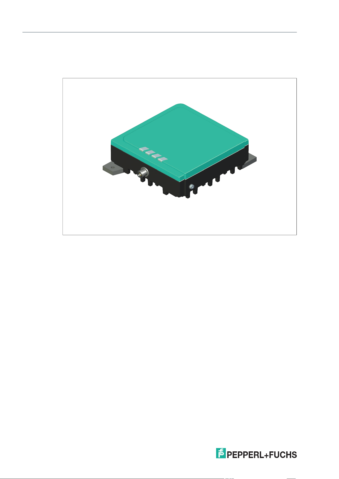
The respective country-specific settings are shown in the table below.
Country-Specific Settings
Note
Transmission License and Country Code
Operation of this device is subject to country-specific regulations. Make sure that the device
used is suitable and approved for the country of use. Information about countries of use can be
found in the datasheet for the relevant device at www.pepperl-fuchs.com. The devices comply
with the respective regulatory requirements of the regions. Country-specific settings cannot be
changed by the user.
Operating
location
Region code UHF band Channel width
Channel
spacing
European Union 01
865 MHz …
868 MHz
200 kHz 600 kHz
USA, Canada,
Mexico
02
902 MHz …
928 MHz
500 kHz 500 kHz
China 03
920 MHz …
925 MHz
250 kHz 250 kHz
India 04
865 MHz …
867 MHz
200 kHz 200 kHz
Brazil,
Colombia
07
915 MHz …
928 MHz
250 kHz 250 kHz
Japan 08
916.7 MHz …
920.5 MHz
200 kHz 1200 kHz
South Korea 09
917.2 MHz …
920.4 MHz
200 kHz 600 kHz
Australia 10
920 MHz …
926 MHz
500 kHz 500 kHz
New Zealand 11
921.5 MHz …
928 MHz
500 kHz 500 kHz
Hong Kong,
Thailand
12
920 MHz …
925 MHz
500 kHz 500 kHz
Malaysia 13
919 MHz ...
923 MHz
500 kHz 500 kHz
Singapore 14
920 MHz …
925 MHz
500 kHz 500 kHz
Morocco 15
867.6 MHz …
868 MHz
200 kHz 200 kHz
Indonesia 16
920 MHz …
923 MHz
500 kHz 500 kHz
Taiwan 17
920 MHz …
928 MHz
500 kHz 500 kHz
Table 4.2

IUH1-F7xx-V1-FR*
UHF general
2026-08
21
Operating
location
Frequency
hopping spread
spectrum
Number of
channels
Channels used
(M)
Center
frequencies
European Union
Parameterizable
frequency list
4
4, 7, 10, 13
(adjustable)
864.9 MHz +
(M x 0.2) MHz
USA, Canada,
Mexico
Frequency
hopping (FHSS)
50 1 … 50 (all)
902.25 MHz +
(M x 0.5) MHz
China
Frequency
hopping (FHSS)
16 2 … 17 (all)
920.125 MHz +
(M x 0.25) MHz
India
Parameterizable
frequency list
10
1 … 10
(adjustable)
864.9 MHz +
(M x 0.2) MHz
Singapore
Parameterizable
frequency list
10
1 … 10
(adjustable up to
4)
865.9 MHz +
(M x 0.2) MHz
Brazil,
Colombia
Frequency
hopping (FHSS)
52 1 … 52 (all)
914.875 MHz +
(M x 0.25) MHz
Japan
Parameterizable
frequency list
4
5, 11, 17, 23
(adjustable)
915.8 MHz +
(M x 0.2) MHz
South Korea
Frequency
hopping (FHSS)
6
1, 4, 7, 10, 13, 16
(all)
917.1 MHz +
(M x 0.2) MHz
Australia
Frequency
hopping (FHSS)
12 1 … 12 (all)
919.75 MHz +
(M x 0.5) MHz
New Zealand
Frequency
hopping (FHSS)
13 1 … 13 (all)
921.5 MHz +
(M x 0.5) MHz
Hong Kong,
Thailand
Frequency
hopping (FHSS)
10 1 … 10 (all)
919.75 MHz +
(M x 0.5) MHz
Malaysia
Frequency
hopping (FHSS)
8 1 … 8 (all)
918.75 MHz +
(M x 0.5) MHz
Singapore
Frequency
hopping (FHSS)
10 1 … 10 (all)
Morocco
Parameterizable
frequency list
2 1, 2 (adjustable)
867.5 MHz +
(M x 0.2 MHz)
Indonesia
Frequency
hopping (FHSS)
6 1 … 6 (all)
919.75 MHz +
(M x 0.5 MHz)
Taiwan
Frequency
hopping (FHSS)
14 1 … 14 (all)
920.25 MHz +
(M x 0.5) MHz
Table 4.3
Note
For information on the maximum radiated power, see datasheet.
2026-08
22
IUH1-F7xx-V1-FR*
Product Description
5 Product Description
5.1 General
Figure 5.1
Functions
The devices from the IUH1-F7xx-V1-FR* series have been developed for reading and writing
passive read/write tags with a UHF operating frequency.
The RFID read/write devices are connected to an IDENTControl evaluation unit using an inte-
grated M12 plug.
Tags that comply with EPC Class 1 Gen 2 (ISO/IEC 18000-63) are supported.
Integrated Antenna
The RFID read/write devices have a circular polarized antenna. As a result, the alignment of a
linearly polarized tag (e.g., horizontal or vertical) is generally not relevant for communication.
IUH1-F7xx-V1-FR*
Product Description
2026-08
23
5.2 Indicators and Operating Elements
LEDs
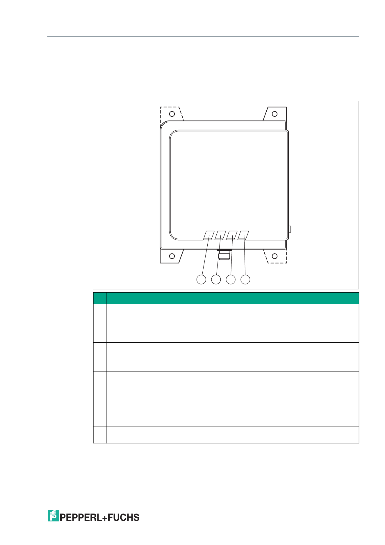
There are four LEDs on the front of the device. The LEDs indicate the device health and the
activity on the air interface.
LED Description
1 Operation LED
• Off: No voltage supply or not ready for operation
• Green: Ready for operation
• Flashing orange (10 Hz): Firmware update is in progress
• Magenta: Supply voltage out of permissible range
2 Communication LED
• Green: Connection to the host
• Green flashing: Communication via the interface
• Red: No connection to the host
3 RFID LED
• Blue: RFID switched on
• Orange: Tag detected
• Red: RF error
• Magenta: Status A (several tags detected) or status 4 (memory
area not available)
• White: Tag outside the set RSSI filter
4 User-defined LED
• This LED can have various functions, depending on the
selected device settings
Table 5.1
1 2 3 4
2026-08
24
IUH1-F7xx-V1-FR*
Installation
6 Installation
6.1 Storage and Transportation
Keep the original packaging. Always store and transport the device in the original packaging.
Store the device in a clean and dry environment. The permitted ambient conditions must be
considered, see datasheet.
6.2 Mounting
Minimum Distances Between Device and Pacemaker
The RFID read/write device is intended for wall mounting or mounting on brackets. Please only
install the device using the existing mounting holes in the housing. The preferred mounting
direction is with the cable connection facing vertically downward.
To mount the RFID read/write device, use at least two screws with a diameter of 4 mm, together
with flat washers and fastening material suitable for the type of mounting surface. The tighten-
ing torque of the screws depends on the type of mounting and the surface. Use a suitable tight-
ening torque to prevent damage.
Warning!
Malfunctions with pacemakers
This device does not exceed the permissible limit values for electromagnetic fields. Maintain
the minimum distance between the device and your pacemaker. The minimum distances of the
respective devices are listed in the table below.
Inadequate distance from the RFID read/write device can result in inhibitions, reprogramming,
or incorrect stimulation pulses.
Device Minimum distance
IUH1-F720-V1-FR* 25 cm
Table 6.1
Note
Do not route the connection cable within the sensing range of the antenna.
Caution!
Mounting the RFID read/write device
Only use the appropriate mounting aids for your device.
Caution!
Mounting the RFID read/write device
Make sure that the RFID read/write device is firmly attached to the surface.
Note
The installation recommendations provided in this document assume the most favorable
ambient conditions. Pepperl+Fuchs does not guarantee fault-free operation in environments
outside the system.
IUH1-F7xx-V1-FR*
Installation
2026-08
25
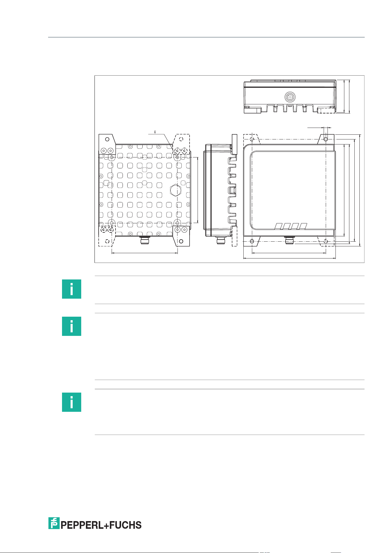
Mounting the RFID read/write device
Figure 6.1
IUH-F720-V1-FR*
112100
100
140
140
151.5
155
170
ø 5.5 (4x)
50.1
50.6
M5 8 (4x)
Note
It is possible to mount the RFID read/write device using a VESA 100x100 bracket.
Note
The RFID read/write device is supplied with two retaining tabs including screws.
The retaining tabs can be used to mount the RFID read/write device if required and fit in all the
provided mounting positions.
To ensure the most compact design possible, the retaining tabs are not pre-assembled at the
factory.
Tighten the fixing screws to a tightening torque of 2 Nm.
Note
The cooling structure of the RFID read/write device must not be covered nor its air circulation
impaired, since this can lead to impermissible heating of the device.
To ensure reliable heat dissipation and trouble-free operation, the cooling structure should be
regularly checked for dirt and cleaned if necessary.
2026-08
26
IUH1-F7xx-V1-FR*
Installation
6.2.1 Minimum Distances
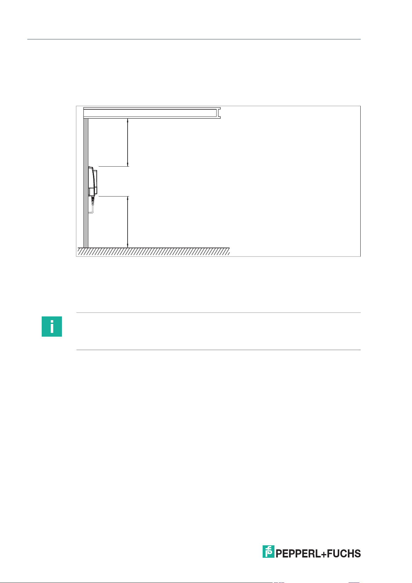
When positioning the RFID read/write device, please observe the minimum distances. The lat-
eral distance between the RFID read/write device and metals or liquids should be at least
(50 cm). The distance between the RFID read/write device and the ground should be at least
(50 cm).
Figure 6.2
During simultaneous operation of several RFID read/write devices, only one RFID read/write
device may ever communicate with a tag at any given time. When arranging the RFID
read/write devices, make sure that the sensing ranges do not overlap if possible. You can
change the transmitter radiated power to enlarge or reduce the size of the sensing range.
Determine the sensing range of each RFID read/write device at the mounting location.
metal carrier
Read / write device
> 50 cm> 50 cm
Note
During mounting, take into account how the RFID read/write devices may cause interference
with each other. The further the RFID read/write devices or the used transmission channels are
from each other, the lower the risk of interference.
IUH1-F7xx-V1-FR*
Installation
2026-08
27
6.3 Connection
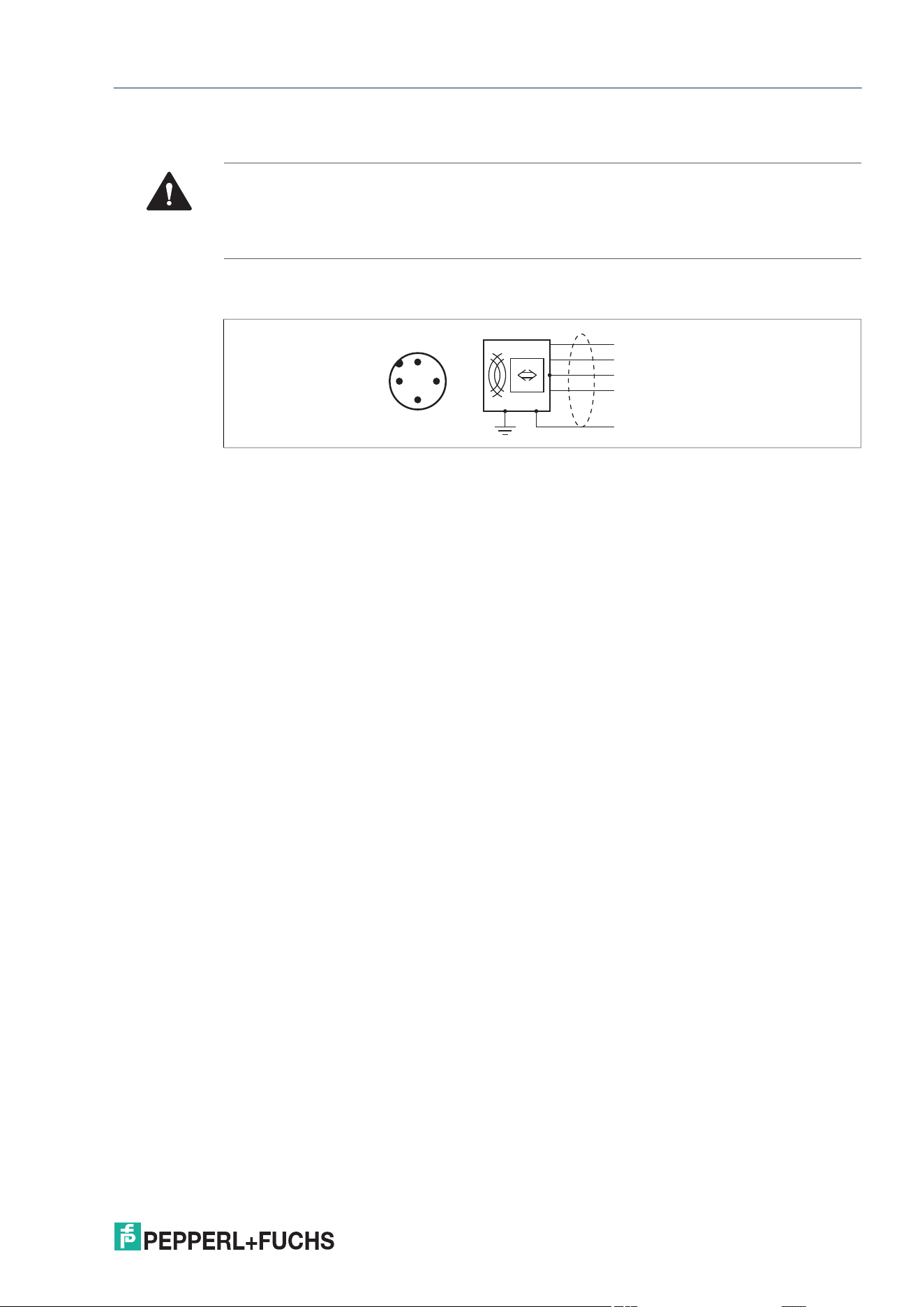
The RFID read/write device is connected to the IDENTControl evaluation unit with an M12 x 1
connector. Further technical details can be found in the datasheet for the relevant device.
Warning!
Incorrect electrical connection
Damage to the device or plant caused by incorrect electrical connection.
Check all connections in the plant before commissioning the device.
Schirm
+
A
-
B
1
2
3
4
1
42
3
2026-08
28
IUH1-F7xx-V1-FR*
Commissioning and Operation
7 Commissioning and Operation
7.1 General Protocol Structure
7.2 Overview of Parameters
7.3 Overview of Commands
Parameter
Parameter
abbreviation
Description Value range Default settings
Table 7.1
Command name
Command
abbreviation
Hex code Description
Single Read Fixcode SF 16#01
One-time read com-
mand to the TID (Bank
10)
Table 7.2

IUH1-F7xx-V1-FR*
Commissioning and Operation
2026-08
29
7.4 Operation via Web Interface

2026-08
30
IUH1-F7xx-V1-FR*
Commissioning and Operation
7.5 REST API

IUH1-F7xx-V1-FR*
Commissioning and Operation
2026-08
31
7.6 Operation on a Control Panel

2026-08
32
IUH1-F7xx-V1-FR*
Commissioning and Operation
7.6.1 Siemens (TIA Portal) with B40

IUH1-F7xx-V1-FR*
Commissioning and Operation
2026-08
33
7.6.2 Rockwell (???) with B40

2026-08
34
IUH1-F7xx-V1-FR*
Service and Maintenance
8 Service and Maintenance
The device is designed and constructed to function stable over long periods of time. For this
reason, regular cleaning or maintenance is unnecessary.
Regularly check the connections and connection cables.
The device is maintenance-free. If the device is defective
• disassemble the device
• send it to Pepperl+Fuchs for repair or
• replace the device.
Any unauthorised tampering or modification is dangerous and will void any warranty and manu-
facturer's liability.

IUH1-F7xx-V1-FR*
Troubleshooting
2026-08
35
9 Troubleshooting
Problem Solution
Interference from several
devices in the direct vicinity
• Check the distance from other devices.
• Change the setting of the transmission channels.
• Reduce the transmitter radiated power.
Status A message
• Check whether there are too many tags in the sensing range:
Remove the tag from the sensing range by placing the tag in a sealed
metal container, for example.
Repeat the read or write operation.
• Use filter commands.
• Determine whether multiple tags have the same UII/EPC.
Table 9.1

2026-08
36
IUH1-F7xx-V1-FR*
Decommissioning and Disposal
10 Decommissioning and Disposal
Decommissioning
For safe decommissioning, see chapter 2.
Disposal
The device, built-in components, packaging, and any batteries contained within
must be disposed in compliance with the applicable laws and guidelines
of the respective country.
IUH1-F7xx-V1-FR*
Appendix
2026-08
37
11 Appendix
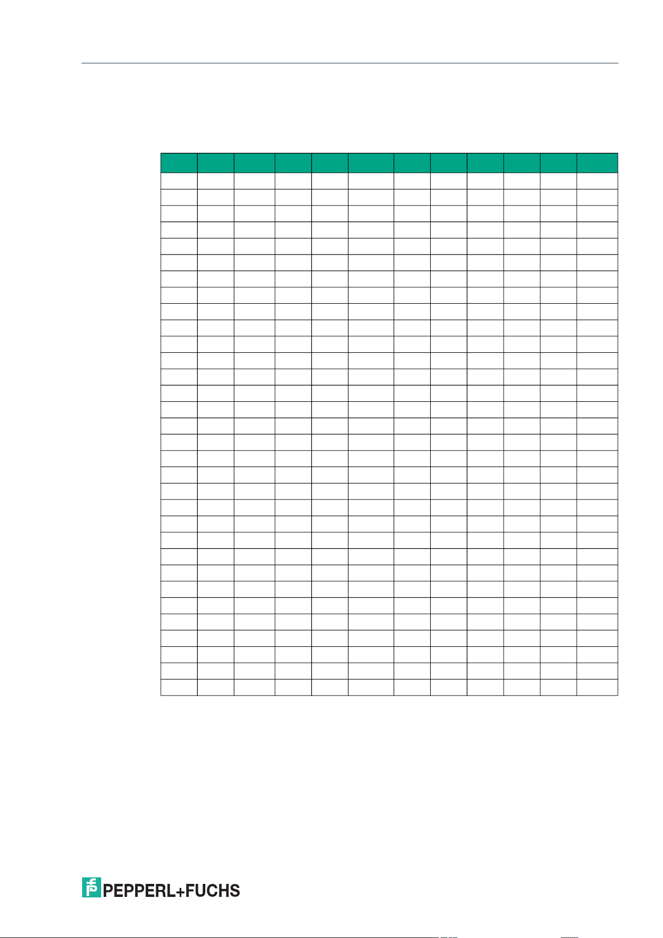
11.1 ASCII table
hex dec ASCII hex dec ASCII hex dec ASCII hex dec ASCII
00 0 NUL 20 32 Space 40 64 @ 60 96 '
01 1 SOH 21 33 ! 41 65 A 61 97 a
02 2 STX 22 34 " 42 66 B 62 98 b
03 3 ETX 23 35 # 43 67 C 63 99 c
04 4 EOT 24 36 $ 44 68 D 64 100 d
05 5 ENQ 25 37 % 45 69 E 65 101 e
06 6 ACK 26 38 & 46 70 F 66 102 f
07 7 BEL 27 39 ' 47 71 G 67 103 g
08 8 BS 28 40 ( 48 72 H 68 104 h
09 9 HT 29 41 ) 49 73 I 69 105 I
0A 10 LF 2A 42 * 4A 74 J 6A 106 j
0B 11 VT 2B 43 + 4B 75 K 6B 107 k
0C 12 FF 2C 44 , 4C 76 L 6C 108 l
0D 13 CR 2D 45 - 4D 77 M 6D 109 m
0E 14 SO 2E 46 . 4E 78 N 6E 110 n
0F 15 SI 2F 47 / 4F 79 O 6F 111 o
10 16 DLE 30 48 0 50 80 P 70 112 p
11 17 DC1 31 49 1 51 81 Q 71 113 q
12 18 DC2 32 50 2 52 82 R 72 114 r
13 19 DC3 33 51 3 53 83 S 73 115 s
14 20 DC4 34 52 4 54 84 T 74 116 t
15 21 NAK 35 53 5 55 85 U 75 117 u
16 22 SYN 36 54 6 56 86 V 76 118 v
17 23 ETB 37 55 7 57 87 W 77 119 w
18 24 CAN 38 56 8 58 88 X 78 120 x
19 25 EM 39 57 9 59 89 Y 79 121 y
1A 26 SUB 3A 58 : 5A 90 Z 7A 122 z
1B 27 ESC 3B 59 ; 5B 91 [ 7B 123 {
1C 28 FS 3C 60 < 5C 92 \ 7C 124 |
1D 29 GS 3D 61 = 5D 93 ] 7D 125 }
1E 30 RS 3E 62 > 5E 94 ^ 7E 126 ~
1F 31 US 3F 63 ? 5F 95 _ 7F 127 DEL

www.pepperl-fuchs.com
Industrial Sensors
Industrial Communication and Interfaces
Enterprise Mobility
Products and Solutions for Hazardous Areas
Pepperl+Fuchs Quality
Download our latest policy here:
www.pepperl-fuchs.com/quality
© Pepperl+Fuchs · Subject to modifications
/ DOCT-9347B