
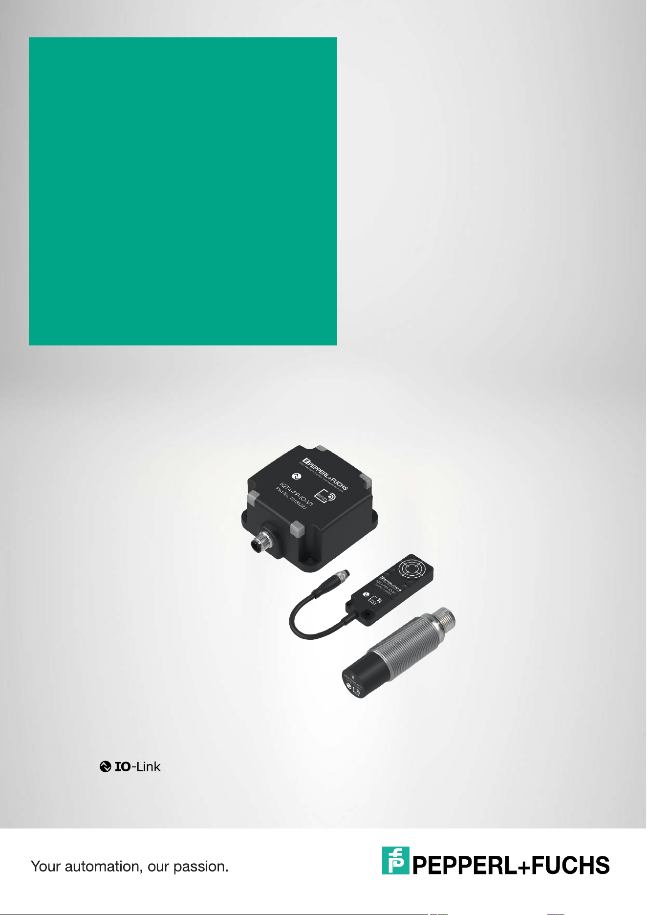
IQT3 / IQT4 Series
RFID Read/Write Devices
for IO-Link, 13.56 MHz, ISO
15693
Manual

With regard to the supply of products, the current issue of the following document is applicable:
The General Terms of Delivery for Products and Services of the Electrical Industry, published
by the Central Association of the Electrical Industry (Zentralverband Elektrotechnik und Elek-
troindustrie (ZVEI) e.V.) in its most recent version as well as the supplementary clause:
"Expanded reservation of proprietorship"
Worldwide
Pepperl+Fuchs Group
Lilienthalstr. 200
68307 Mannheim
Germany
Phone: +49 621 776 - 0
E-mail: [email protected]s.com
North American Headquarters
Pepperl+Fuchs Inc.
8093 Darrow Road
Twinsburg, Ohio 44087
+1 330 425-3555
United States of America
E-mail: [email protected]
Asia Headquarters
Pepperl+Fuchs Pte. Ltd.
P+F Building
18 Ayer Rajah Crescent
Singapore 139942
Phone: +65 6779-9091
E-mail: [email protected]
https://www.pepperl-fuchs.com

IQT3 / IQT4 Series
Contents
2026-05
3
1 Introduction................................................................................................................ 5
1.1 Content of this Document............................................................................. 5
1.2 Target Group, Personnel ............................................................................... 5
1.3 Intended Use .................................................................................................. 5
1.4 Symbols Used ................................................................................................ 6
1.5 Definitions ...................................................................................................... 6
1.6 Terms and Abbreviations .............................................................................. 7
2 Cybersecurity............................................................................................................. 9
3 Certificates and Approvals ..................................................................................... 10
3.1 General ......................................................................................................... 10
3.2 CE Marking ...................................................................................................10
3.3 FCC Compliance Statement........................................................................ 10
3.4 IC Compliance Statement ........................................................................... 11
3.5 UL Information ............................................................................................. 11
4 Product Description ................................................................................................ 13
4.1 Product Description .................................................................................... 13
4.2 Dimensions...................................................................................................16
4.3 Indicators......................................................................................................17
4.4 Electrical Connection .................................................................................. 18
4.5 IO-Link Interface Properties ....................................................................... 18
4.6 Accessories.................................................................................................. 18
4.6.1 IO-Link master .................................................................................................................. 18
4.6.2 RFID Tag........................................................................................................................... 18
4.6.3 Connection Cable............................................................................................................. 19
5 Installation................................................................................................................ 20
5.1 Storage and Transportation ........................................................................ 20
5.2 Unpacking .................................................................................................... 20
5.3 Mounting and Connection .......................................................................... 20
5.4 Minimum Distances ..................................................................................... 21
5.5 Main and Auxiliary Fields............................................................................ 22
5.6 Ambient Temperature Range ...................................................................... 26

IQT3 / IQT4 Series
Contents
2026-05
4
6 Commissioning and Operation...............................................................................27
6.1 Operating Modes..........................................................................................27
6.2 Tag 13.56 MHz ISO15693.............................................................................27
6.3 Sensing Range .............................................................................................28
6.4 Multiple Tags in Sensing Range .................................................................28
7 Easy Mode ................................................................................................................30
7.1 Command Overview ....................................................................................30
7.2 Basic Structure of the Process Data..........................................................30
7.2.1 Output Process Data (PLC -> Device)............................................................................... 30
7.2.2 Input Process Data (Device -> PLC) ................................................................................. 31
7.2.3 Flowcharts ........................................................................................................................ 36
7.2.4 Timing............................................................................................................................... 39
7.2.5 Interruption of IO-Link Communication ............................................................................. 40
7.3 Easy Mode with PACTware ..........................................................................40
8 ExpertMode ..............................................................................................................49
8.1 Basic Command Process............................................................................49
8.2 Legend ..........................................................................................................49
8.3 Structure of OUTPUT telegram...................................................................50
8.4 Structure of INPUT telegram.......................................................................51
8.5 Handshake Procedure .................................................................................51
8.6 Command Overview ....................................................................................53
8.6.1 Read/Write Commands..................................................................................................... 56
8.6.2 System Commands ........................................................................................................ 119
8.6.3 Configuration Commands ............................................................................................... 122
8.6.3.1 Basic Command Structure................................................................................................... 122
8.6.3.2 Parameter Overview ............................................................................................................ 124
8.6.3.3 Parameters.......................................................................................................................... 127
8.6.3.4 Parameter Examples ........................................................................................................... 137
8.7 Error / Status Messages............................................................................151
9 Appendix.................................................................................................................152
9.1 Troubleshooting .........................................................................................152
9.2 ASCII Table..................................................................................................152
IQT3 / IQT4 Series
Introduction
2026-05
5
1 Introduction
1.1 Content of this Document
This document contains information required to use the product in the relevant phases of the
product life cycle. This may include information on the following:
• Product identification
• Delivery, transport, and storage
• Mounting and installation
• Commissioning and operation
• Maintenance and repair
• Troubleshooting
• Dismounting
• Disposal
The documentation comprises the following parts:
• This document
• Datasheet
• IO-Link parameter datasheet
The documentation may comprise the following parts, if applicable:
• EU-type examination certificate
• EU declaration of conformity
• Attestation of conformity
• Certificates
• Control drawings
• Instruction manual
• Functional safety manual
• Cybersecurity documentation
• Other documents
1.2 Target Group, Personnel
Responsibility for planning, assembly, commissioning, operation, maintenance, and dismount-
ing lies with the plant operator.
Only appropriately trained and qualified personnel may carry out mounting, installation, com-
missioning, operation, maintenance, and dismounting of the product. The personnel must have
read and understood the instruction manual and the further documentation.
Prior to using the product make yourself familiar with it. Read the document carefully.
1.3 Intended Use
Always operate the device as described in these instructions. Only in this way, the safe function
of the device and the connected systems is guaranteed.
The protection of operating personnel and plant is only given if the device is used in accor-
dance with its intended use.
Note
For full information on the product, refer to the further documentation on the Internet at
www.pepperl-fuchs.com.
Note
For specific device information such as the year of construction, scan the QR code
on the device. As an alternative, enter the serial number in the serial number search
at www.pepperl-fuchs.com/device-information.
2026-05
6
IQT3 / IQT4 Series
Introduction
1.4 Symbols Used
This document contains symbols for the identification of warning messages and of informative
messages.
Warning Messages
You will find warning messages, whenever dangers may arise from your actions. It is mandatory
that you observe these warning messages for your personal safety and in order to avoid prop-
erty damage.
Depending on the risk level, the warning messages are displayed in descending order as fol-
lows:
Informative Symbols
Action
This symbol indicates a paragraph with instructions. You are prompted to perform an action or
a sequence of actions.
Danger!
This symbol indicates an imminent danger.
Non-observance will result in personal injury or death.
Warning!
This symbol indicates a possible fault or danger.
Non-observance may cause personal injury or serious property damage.
Caution!
This symbol indicates a possible fault.
Non-observance could interrupt the device and any connected systems and plants, or result in
their complete failure.
Note
This symbol brings important information to your attention.
Tip
This symbol brings an useful tip to your attention.
Example
This symbol provides an example of the issue described.

IQT3 / IQT4 Series
Introduction
2026-05
7
1.5 Definitions
The data representation format varies in the following documentation. The following formats are
used:
ASCII
Example: "A"; "B"; "1"; "2"
An ASCII character corresponds to one byte. 2
8
= 256 different characters can be represented.
Binary
Example: 1001
bin
Binary numbers are indicated by the suffix
bin
.
DECIMAL
Example: 1234
Decimal numbers are shown without any additional notation.
HEX
Example: 16#41; 16#42; 16#31; 16#32
The hexadecimal representation of a byte consists of two digits (e.g., 16#41). The left portion is
the high-order nibble (16#4x). The right portion is the low-order nibble (16#x1). The value
range extends from 16#00 to 16#FF.
Note
In the TIA Portal from Siemens, hexadecimal numbers are displayed as follows:
Example:
16#00 (equivalent to 0x00)

2026-05
8
IQT3 / IQT4 Series
Introduction
1.6 Terms and Abbreviations
Terms
Abbreviations
COM Mode The IO-Link data transfer rate
Tag Mobile data carrier containing user data and a unique number
Device ID Identification number of the device
Easy Mode Communication protocol for simple data access of a read/write device; no
function block required
Expert Mode Communication protocol for high-performance data access of the RFID
read/write device; the use of a function block is required
Fixed code Unique and unchangeable number of a read/write tag; Unique Identifier
UID
IODD IO Device Description; file with information about IO-Link parameters of an
IO-Link-enabled device
IO-Link Communication system for the connection of intelligent sensors and actua-
tors via point-to-point communication
IO-Link master Interface to higher-level control; controls the communication to connected
IO-Link devices
IO-Link device Intelligent sensor or actuator for connecting to an IO-Link master; has
device-specific IO-Link parameters
IO-Link parame-
ters
Device-specific information about an IO-Link device; parameters are
stored in an IODD; acyclic change of the parameters
IO-Link protocol Version of the supported IO-Link communication; V1.0 or V1.1
IQC Pepperl+Fuchs-specific designation of a 13.56 MHz read/write tag
ISO/IEC 15693 Standard for data tranmsission for a 13.56 MHz RFID system
ISDU Indexed Service Data Unit
PACTware Parameterization software for access to IO-Link parameters
Port type Type of IO-Link port
RSSI Indicator for the receive field strength
SIO Mode Standard IO mode; mode for conventional signal transmission without IO-
Link data
1
1.Not supported
PLC Programmable logic controller; device for controlling a machine or plant
UID See "Fixed code"
Vendor ID Identification number of the device manufacturer, Pepperl+Fuchs: 0x01
FCC Federal Communications Commission
HF High Frequency
IC Industry Canada
ISO International Standardisation Organisation
RFID Radio Frequency Identification
RSSI Received Signal Strength Indicator
PLC Programmable Logic Controller
Tag Read/write tag; tag
UID Unique Identifier

IQT3 / IQT4 Series
Cybersecurity
2026-05
9
2 Cybersecurity
The device is secure developed according to IEC 62443-4-1 for the application area
defined here.
To ensure cybersecure operation and to protect the device, implement the following measures.
Security Context
The RFID read/write device is designed for operation with an IO-Link master from Pep-
perl+Fuchs.
The Communication is realized via a point-to-point connection.
Physically protect the device and the application against unauthorized access.
Firmware updates are signed by Pepperl+Fuchs. This ensures protection against tampered
firmware.
For manufacturing purposes, the device features a proprietary manufacturer's service interface
that uses the existing connection lines.
After the device is switched on, the service interface is disabled after a defined time.
The service interface is deactivated after 50 ms.
Maintenance and Management
Operate the device using the latest firmware. The latest firmware can be found
at https://www.pepperl-fuchs.com/cybersecurity.
Check the website regularly for security advisories publications: https://www.pepperl-
fuchs.com/cybersecurity.
Report incidents to the manufacturer.
Decommissioning
The device stores adjustable parameters and operating data.
All parameters, operating data, and reset options are specified in the IO-Link parameter docu-
mentation.
To delete data, you have to physically destroy the device.
2026-05
10
IQT3 / IQT4 Series
Certificates and Approvals
3 Certificates and Approvals
3.1 General
This manual applies to several types and variants of the device. The applicable approvals can
be found in the relevant data sheet for your device. Further approvals are available on request.
3.2 CE Marking
This product was developed and manufactured in line with the applicable European standards
and directives.
3.3 FCC Compliance Statement
This device complies with Part 15 of the FCC Rules. Operation is subject to the following two
conditions:
1. this device may not cause harmful interference, and
2. this device must accept any interference received, including interference that may cause
undesired operation.
Attention:
Changes or modifications not expressly approved by the party responsible for compliance
could void the user's authority to operate the equipment.
To comply with FCC Part 15 rules in the United States, the system must be professionally
installed to ensure compliance with the Part 15 certification. It is the responsibility of the opera-
tor and professional installer to ensure that only certified systems are deployed in the United
States. The use of the system in any other combination (such as co-located antennas transmit-
ting the same information) is expressly forbidden.
To comply with FCC RF exposure compliance requirements, the antennas used for this trans-
mitter must be installed to provide a minimum separation distance from all persons as specified
in the table below and must not be co-located or operated in conjunction with any other
antenna or transmitter.
Note
A Declaration of Conformity can be requested from the manufacturer or downloaded from
www.pepperl-fuchs.com.
Note
This equipment has been tested and found to comply with the limits for a Class A digital device,
pursuant to Part 15 of the FCC Rules. These limits are designed to provide reasonable
protection against harmful interference when the equipment is operated in a commercial
environment. This equipment generates, uses, and can radiate radio frequency energy and, if
not installed and used in accordance with the instruction manual, may cause harmful
interference to radio communications. Operation of this equipment in a residential area is likely
to cause harmful interference, in which case the user will be required to correct the interference
at their own expense.
Type/Design Minimum separation distance
IQT3-FP-IO-V1 20 cm
IQT4-*-IO-V1 20 cm
IQT3 / IQT4 Series
Certificates and Approvals
2026-05
11
3.4 IC Compliance Statement
This device contains license-exempt transmitter(s)/receiver(s) that comply with Innovation, Sci-
ence and Economic Development Canada's license-exempt RSS(s). Operation is subject to
the following two conditions:
1. This device may not cause interference.
2. This device must accept any interference, including interference that may cause unde-
sired operation of the device.
L’émetteur/récepteur exempt de licence contenu dans le présent appareil est conforme aux
CNR d’Innovation, Sciences et Développement économique Canada applicables aux appar-
eils radio exempts de licence. L'exploitation est autorisée aux deux conditions suivantes:
1. L'appareil ne doit pas produire de brouillage.
2. L'appareil doit accepter tout brouillage radioélectrique subi, même si le brouillage est sus-
ceptible d'en compromettre le fonctionnement.
To comply with IC RF exposure compliance requirements, the antennas used for this transmit-
ter must be installed to provide a minimum separation distance from all persons as specified in
the table below and must not be co-located or operated in conjunction with any other antenna
or transmitter.
3.5 UL Information
IQT3 Series
This device is for indoor use only.
This device may be operated at altitudes of up to 5000 m.
The ambient temperature range is from -20 °C … +70 °C for operation with non-transmission
periods, or -25 °C … +55 °C for continuous operation. The pollution degree is 2.
The maximum relative humidity is 80 % at temperatures up to 31 °C, decreasing linearly to
50 % relative humidity at 40 °C.
The nominal supply voltage is 24 V
DC
; the voltage range is 18 V ... 30 V
DC
. The supply must
be an LEC (Limited Energy Circuit), LPS (Limited Power Source), or Class 2. Overvoltage
Category II applies.
The enclosure type is 1.
The products are intended for use in or with industrial machinery applications as defined in the
Electrical Standard for Industrial Machinery, NFPA 79.
Degree of protection (IP67) is not included in the UL approval. The degree of protection is
tested by Pepperl+Fuchs SE.
External circuits intended to be connected to this unit must be galvanically isolated from the
mains supply or hazardous live voltages by reinforced or double insulation and must meet the
limits of Clauses 6.3 and 9.4 of UL 61010-1.
Type/Design Minimum separation distance
IQT3-FP-IO-V1 20 cm
IQT4-*-IO-V1 20 cm
Caution!
Connection cable Specifications
The maximum permissible temperature of the connection cable must be at least +70 °C. The
minimum diameter of the connection cable must be 22 AWG or 0.34 mm
2
.

2026-05
12
IQT3 / IQT4 Series
Certificates and Approvals
IQT4 Series
The ambient temperature range is from -25 °C … +70 °C for operation with non-transmission
periods.
The nominal supply voltage is 24 V
DC
; the voltage range is 18 V ... 30 V
DC
. Supply must be
CLASS 2.
Degree of protection (IP67) is not included in the UL approval. The degree of protection is
tested by Pepperl+Fuchs SE.
Caution!
Connection cable Specifications
The device must be connected exclusively using any R/C cord (type CYJV/7 or CYJV2/8) with
appropriate ratings.
IQT3 / IQT4 Series
Product Description
2026-05
13
4 Product Description
4.1 Product Description
Function
The IQT3/IQT4-series read/write devices are designed for writing and reading passive tags in
the 13.56 Mhz frequency range.
The read/write devices feature an IO-Link communication interface and are connected to an
IO-Link master via an integrated M12 plug.
Use and Application
The IQT3-series read/write devices have an extended sensing range of up to 30 cm and are
therefore especially suitable for applications in which tags need to be reliably identified at a
greater distance or at a higher passing speed.
The IQT4-series read/write devices are available in various housing designs and have a sens-
ing range of up to 20 cm, depending on the design. This makes them suitable for applications
with limited installation space.
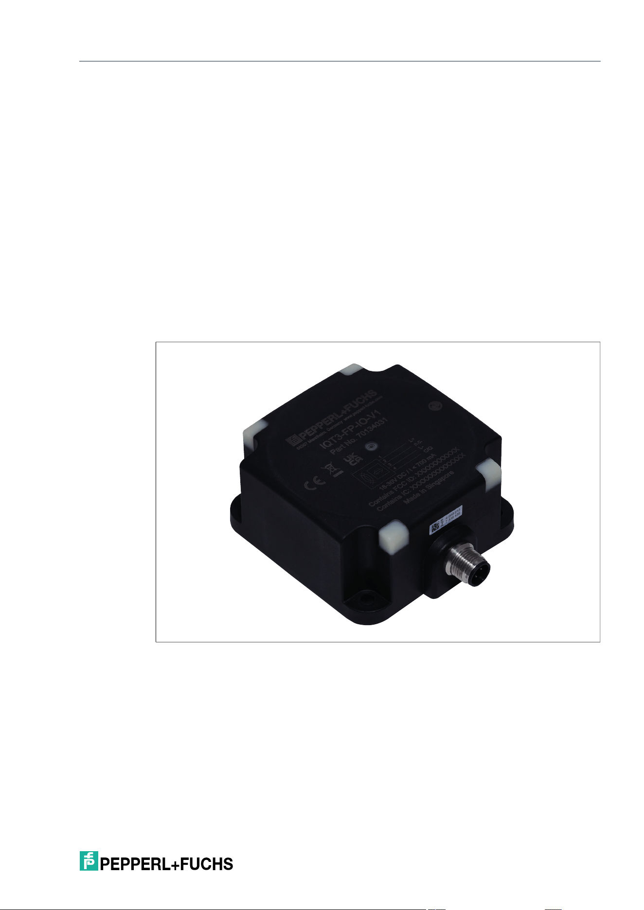
Figure 4.1 IQT3-FP-IO-V1
2026-05
14
IQT3 / IQT4 Series
Product Description
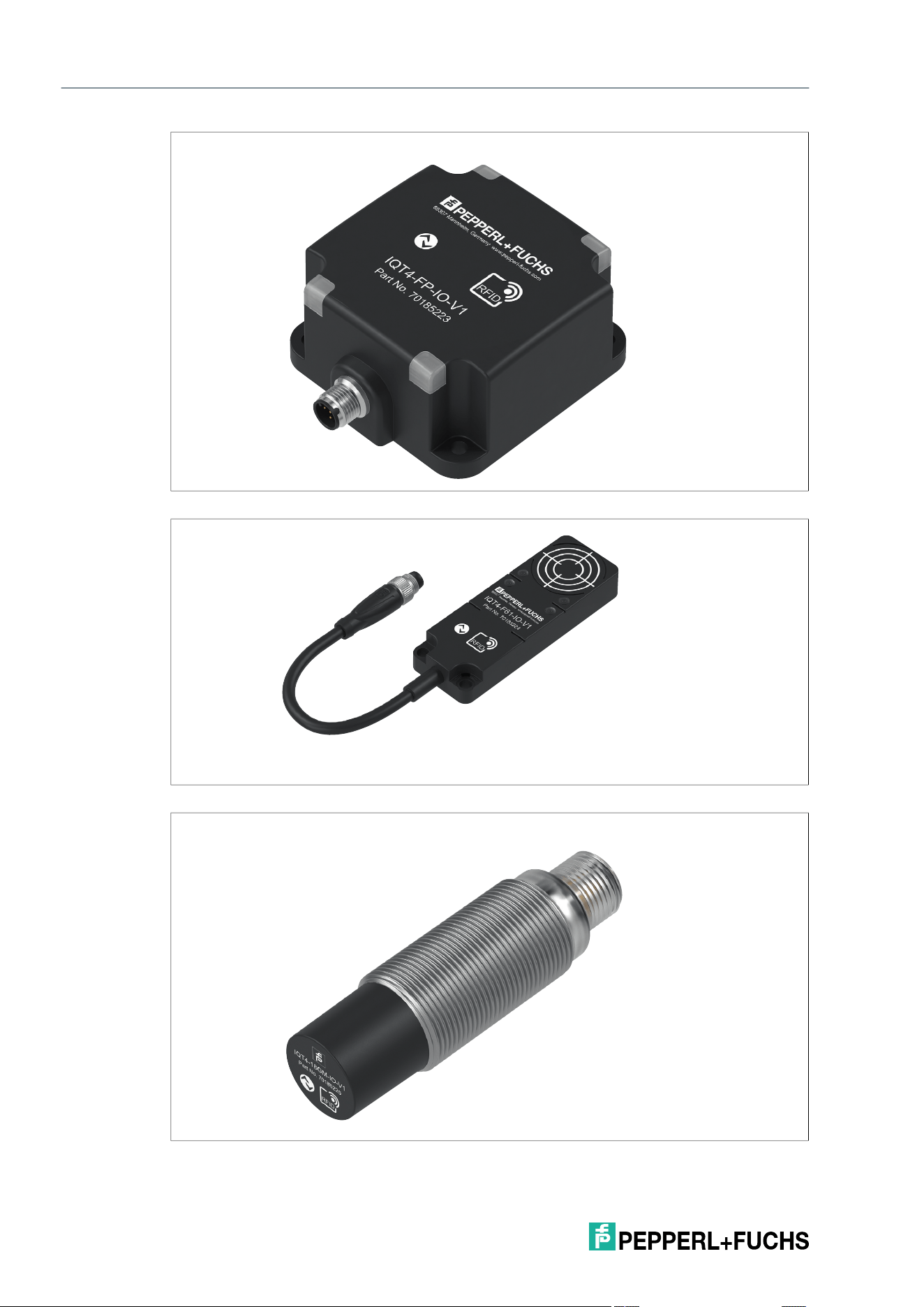
Figure 4.2 IQT4-FP-IO-V1
Figure 4.3 IQT4-F61-IO-V1
Figure 4.4 IQT4-18GM-IO-V1
IQT3 / IQT4 Series
Product Description
2026-05
15
4.2 Dimensions
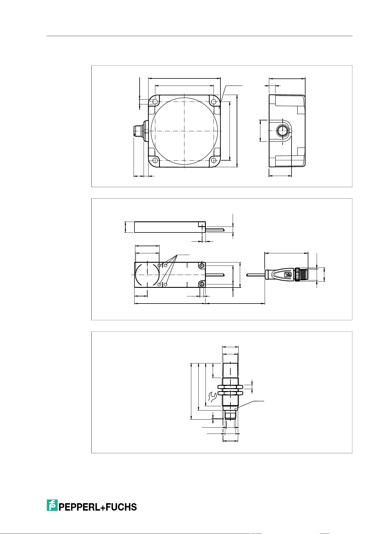
Figure 4.5 IQT3-FP-IO-V1 / IQT4-FP-IO-V1
Figure 4.6 IQT4-F61-IO-V1
Figure 4.7 IQT4-18GM-IO-V1
65
LED (4x)
80
65
80
7
40
23.76
ø 5.4 (4x)
24.93
12 5
6.55
20.83.6
80
ø 4.4
3.6
14.8
L
M12 x 1
48.2
ø 27
ø 26
14
28
12
LED
1
16
48.5
53.5
63.5
ø 16.4
M18 x 1
ø 16.8
ø 8.4 ± 0.1
M12 x 1
24
4
LED
2026-05
16
IQT3 / IQT4 Series
Product Description
4.3 Indicators
The RFID read/write devices have four LEDs to indicate the operating state. The various indica-
tors denote:
4.4 Electrical Connection
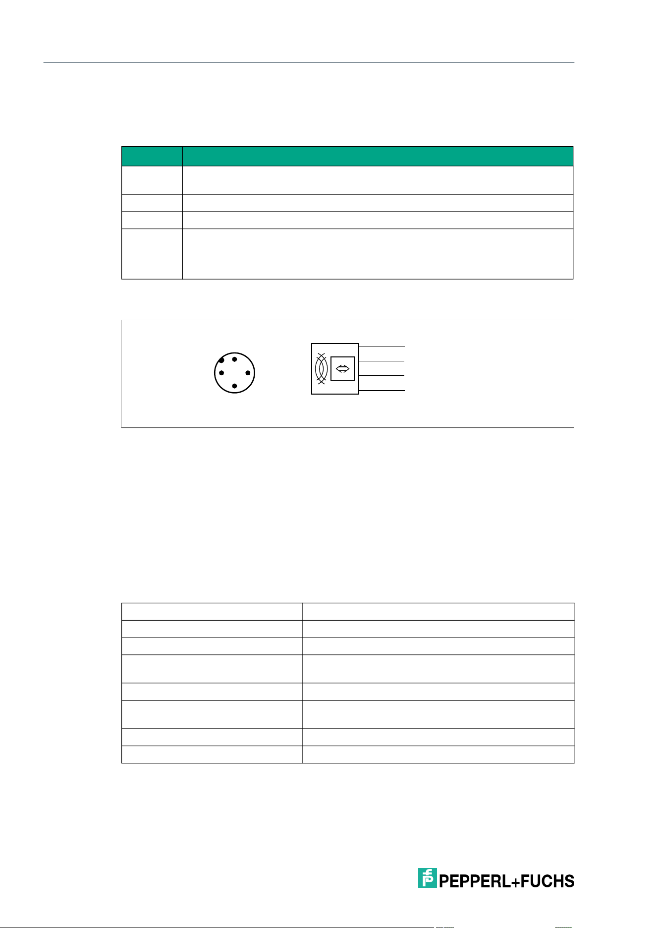
The RFID read/write device is connected to an IO-Link master via a point-to-point connection.
According to the IO-Link installation instructions, the length of the connection line should not
exceed 20 meters. The RFID read/write device is powered via the IO-Link master. For technical
details, refer to the product datasheet.
4.5 IO-Link Interface Properties
LED Description
Green On: Device is ready for operation, no IO-Link communication
Flashing: IO-Link communication active
Blue On: Write/read attempt is being performed
Orange On: Write/read attempt was successful
Red On: Interference from external signals in the sensing range, range may be lim-
ited.
Slow flashing (1 Hz): Metal interference
Fast flashing (10 Hz): Excess temperature
Pin 1 L+ +24 V
Pin 2 n.c. Not connected
Pin 3 L- 0 V/GND
Pin 4 C/Q C/Q
L+
n.c.
L-
C/Q
1
2
3
4
1
42
3
IO-Link version: 1.1
Data transmission rate COM3 (230.4 kbits/s)
Min. cycle time 4 ms
Process data Input 32 bytes
Output 32 bytes
SIO mode support No
Compatible master port type Class A
Class B
Device ID See product datasheet
Vendor ID 1 (0x0001)

IQT3 / IQT4 Series
Product Description
2026-05
17
4.6 Accessories
4.6.1 IO-Link Master
You can connect the RFID read/write devices to any IO-Link master, as long as it supports the
IO-Link standard V1.1 and has a sufficient power supply. A selection of available IO-Link mas-
ters from Pepperl+Fuchs can be found online at www.pepperl-fuchs.com on the product page
of the respective read/write device.
4.6.2 RFID Tag
The RFID read/write device can access any tag that complies with the ISO15693 standard. A
selection of available RFID tags from Pepperl+Fuchs can be found online at www.pepperl-
fuchs.com on the product page for the respective read/write device.
4.6.3 Connection Cable
To connect the RFID read/write devices to an IO-Link master, you can use unshielded, 3- or 4-
wire cables with an M12 plug and a maximum length of 20 m. You can find a selection of avail-
able connection cables from Pepperl+Fuchs online at www.pepperl-fuchs.com on the product
page for the respective read/write device.
Note
Check the performance of the power supply at the connector of the master and the cable
cross-section of the connecting cable to ensure stable communication.
2026-05
20
IQT3 / IQT4 Series
Installation
5 Installation
5.1 Storage and Transportation
Keep the original packaging. Always store and transport the device in the original packaging.
Store the device in a clean and dry environment. The permitted ambient conditions must be
considered, see datasheet.
5.2 Unpacking
Check the product for damage while unpacking. In the event of damage to the product, inform
the post office or parcel service and notify the supplier.
Check the package contents against your purchase order and the shipping documents for:
• Delivery quantity
• Device type and version in accordance with the type label
• Any accessories ordered
Retain the original packaging in case you have to store or ship the device again at a later date.
Should you have any questions, please contact Pepperl+Fuchs.
5.3 Mounting and Connection
Use 4 screws (4 mm diameter) to secure the IQT3-FP-IO-V1 and IQT4-FP-IO-V1 read/write
devices.
Use 2 screws (4 mm diameter) to secure the IQT4-F61-IO-V1 read/write device.
When securing the read/write devices, use suitable flat washers and fixtures that are appropri-
ate for the type of surface.
The tightening torque of the screws depends on the type of fixture. We recommend using a
tightening torque of 1.8 Nm. Use a maximum tightening torque of 2.4 Nm to prevent damage to
the plastic housing.
Use suitable mounting material, such as nuts and mounting aids, to secure the IQT4-18GM-IO-
V1 read/write device.
Note
The RFID read/write devices are designed for wall mounting and mounting on brackets
indoors.
Mount the read/write device on a flat surface and secure it using only the holes provided on the
housing.
Warning!
Processes started in an uncontrolled manner jeopardize the plant
Before commissioning, ensure that there is no risk to the system into which the device is inte-
grated.
Caution!
Hot surfaces
Risk of burns when handling the read/write device! After switching off the device, allow it to cool
down for at least half an hour before touching it.
IQT3 / IQT4 Series
Installation
2026-05
21
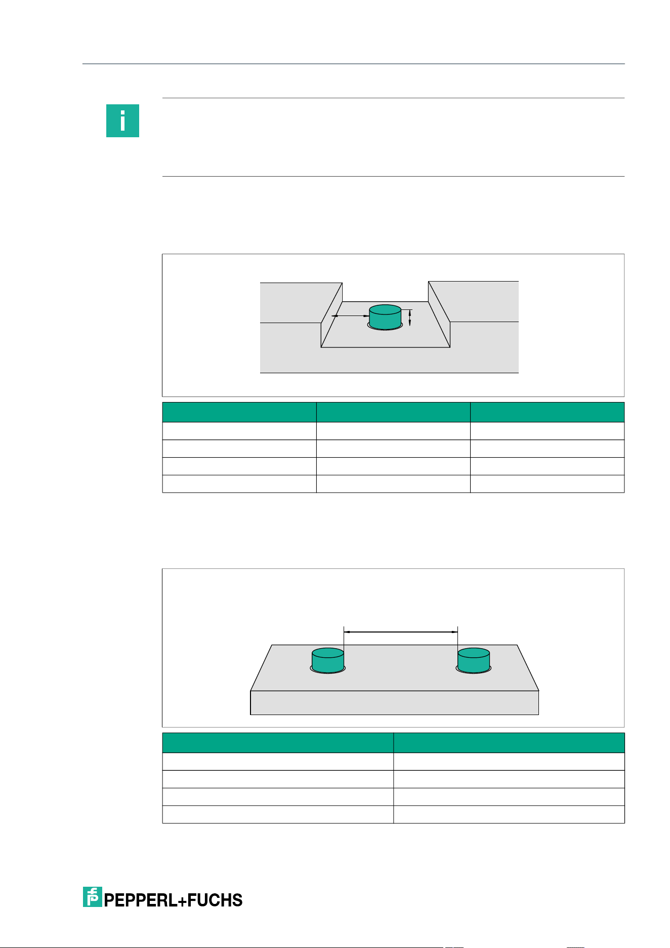
5.4 Minimum Distances
For flush mounting in metal surfaces, a lateral minimum distance X to metal must be observed.
For flush mounting in metal, a protrusion Y above the mounting surface must be observed.
When mounting multiple RFID read/write devices next to one another, a minimum distance Z
must be maintained. This distance prevents the read/write devices from interfering with one
another.
When mounting multiple read/write devices, maintain the following minimum distances:
Note
Do not route the connection cable for the read/write device and the IO-Link master within the
operating range of the tag. Keep a distance of at least 10 cm.
If the distance is too small, in rare cases this may lead to incorrect detection of tags due to
inductive coupling via the connection cable.
Read/write device X Y
IQT3-FP-IO-V1 XX XX
IQT4-FP-IO-V1 XX XX
IQT4-F61-IO-V1 XX XX
IQT4-18GM-IO-V1 XX XX
Read/write device Z
IQT3-FP-IO-V1 750 mm
IQT4-FP-IO-V1 XX
IQT4-F61-IO-V1 XX
IQT4-18GM-IO-V1 XX
X
Y
Z
2026-05
22
IQT3 / IQT4 Series
Installation
5.5 Main and Auxiliary Fields
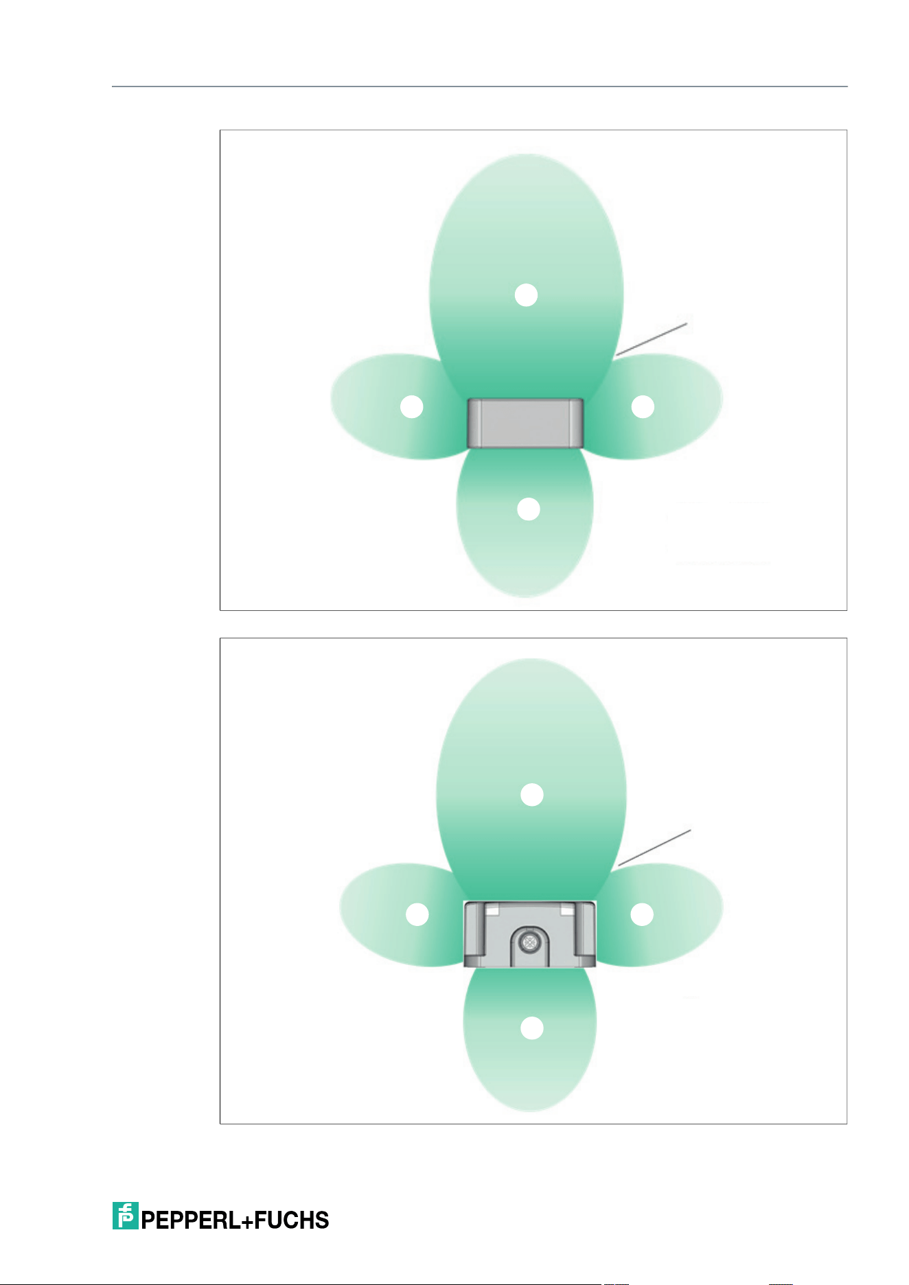
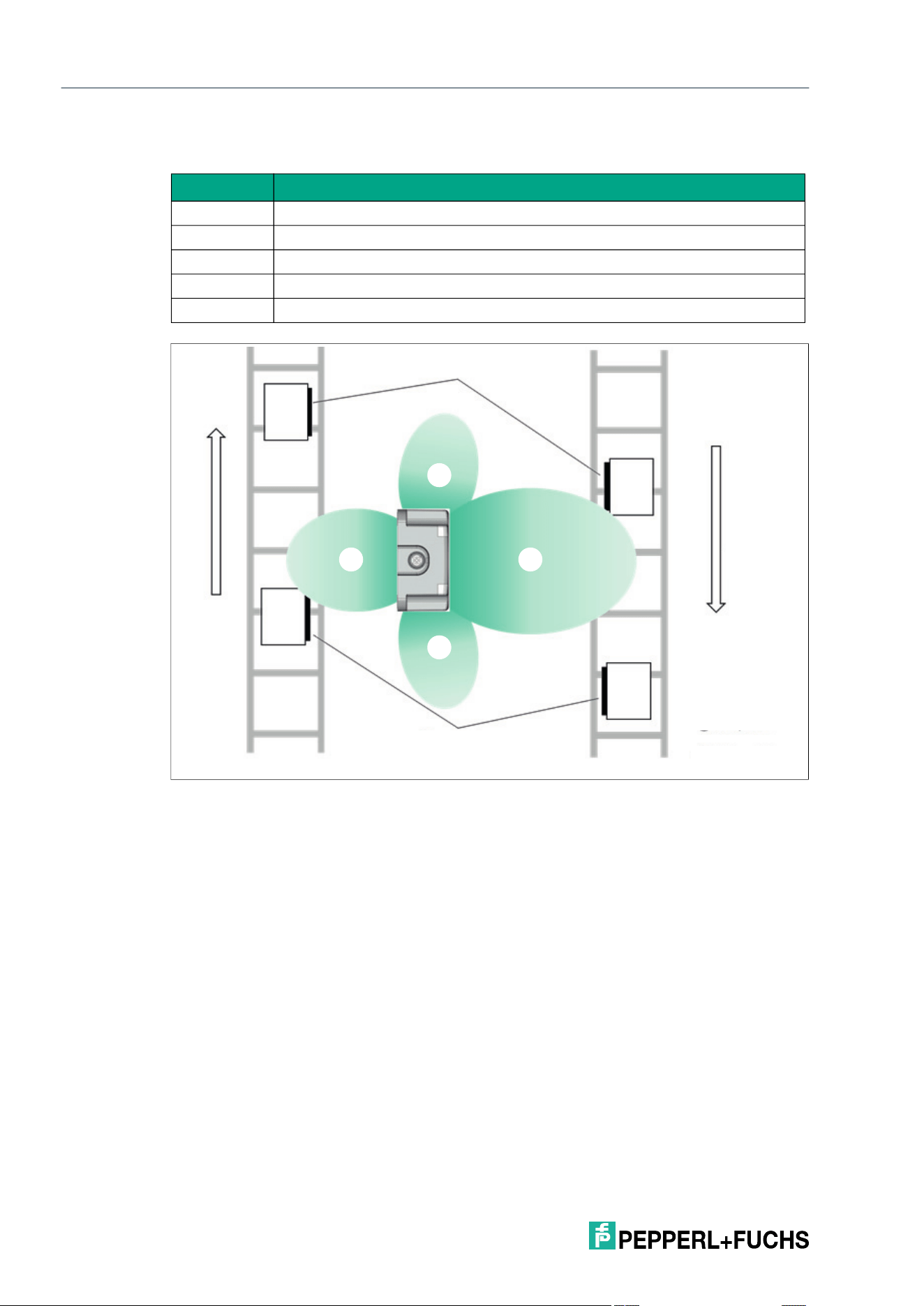
The RFID read/write devices have a main field and auxiliary fields. However, the auxiliary fields
should only be used in exceptional cases during project planning, because the read/write dis-
tances are very limited. It is not possible to provide precise details regarding the geometries of
the auxiliary fields, because the values depend heavily on the operating distance and the appli-
cation.
In dynamic mode, it must be considered that the tag may be temporarily lost during the transi-
tion from the main field to the auxiliary field due to field gaps.
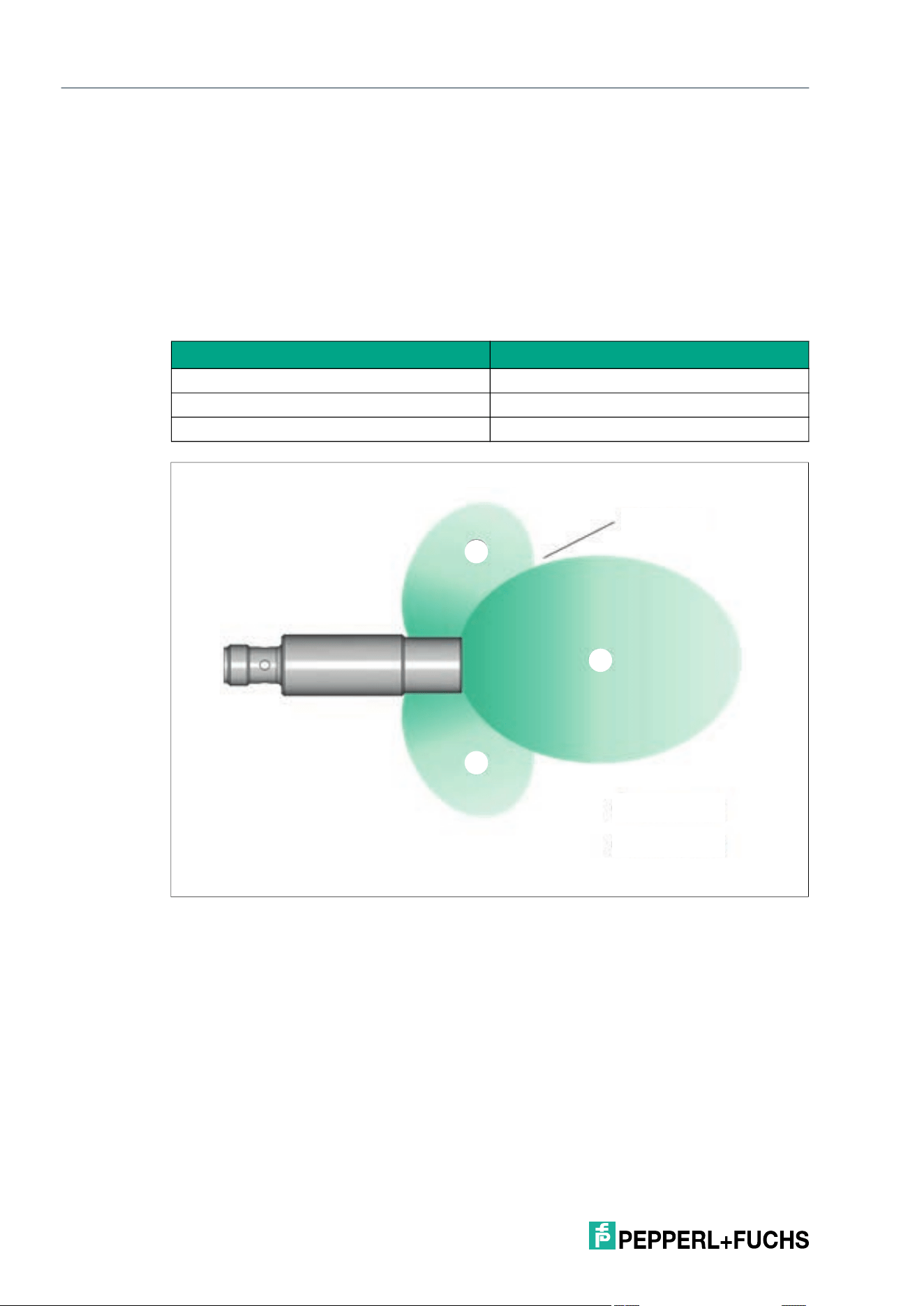
The typical main and auxiliary fields of the three device versions are shown schematically
below.
Figure 5.1 Schematic representation of the main and auxiliary fields IQT4-18GM-IO-V1
Legend Designation
1 Main field
2 Auxiliary field
3 Field gap
3
2
2
1
IQT3 / IQT4 Series
Installation
2026-05
23
Figure 5.2 Schematic representation of the main and auxiliary fields IQT4-F61-IO-V1
Figure 5.3 Schematic representation of the main and auxiliary fields IQT3-FP-IO-V1 / IQT4-FP-IO-
V1
2
2
2
1
3
1
2
2
2
3
2026-05
24
IQT3 / IQT4 Series
Installation
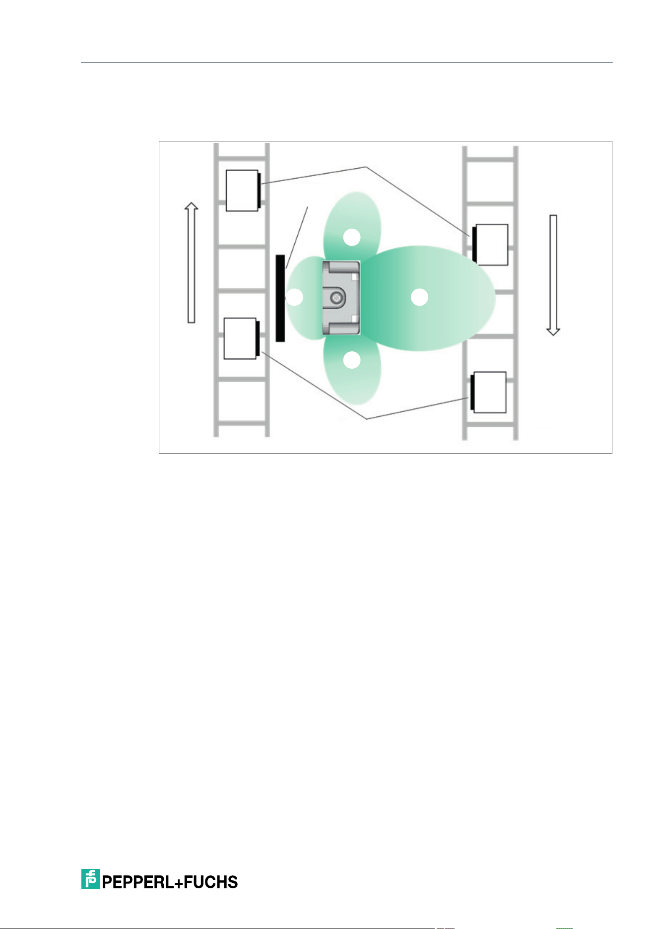
If no shielding measures are in place, the RFID read/write device can detect tags via one of the
auxiliary fields.
Figure 5.4 Schematic representation of auxiliary fields without shielding
Legend Designation
1 Main field
2 Auxiliary field
3 Conveying direction
4 Tag
5 Metal shielding
2
3
3
4
4
2
2
1
IQT3 / IQT4 Series
Installation
2026-05
25
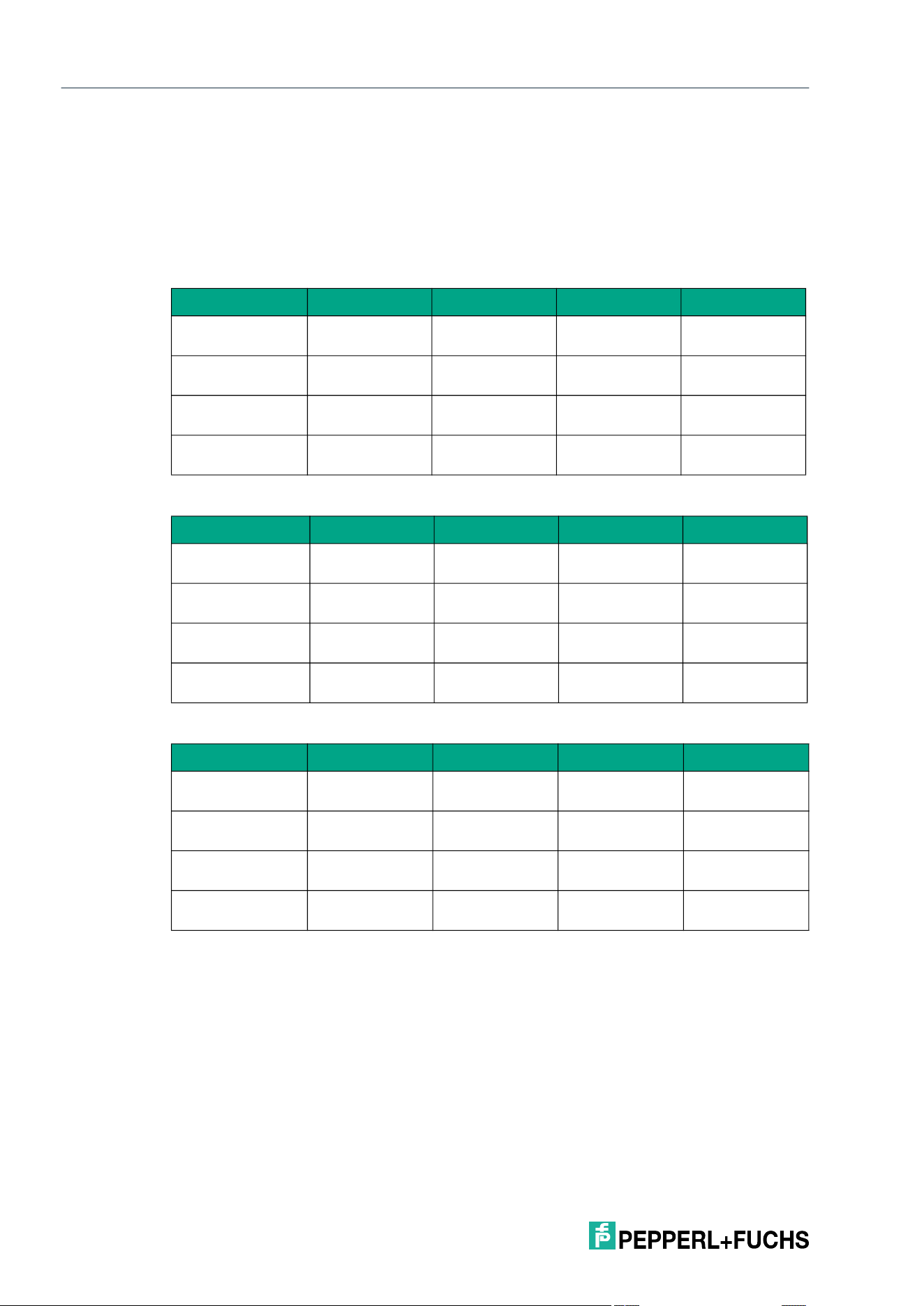
Metal shielding is required to prevent unwanted detection of tags via the auxiliary field.
Typical main and auxiliary fields are shown below, but with metal shielding. Metal shielding pre-
vents tags from being detected via the auxiliary field of the RFID read/write device.
Figure 5.5 Schematic representation of auxiliary fields with shielding
2
2
2
1
3
3
4
4
5
2026-05
26
IQT3 / IQT4 Series
Installation
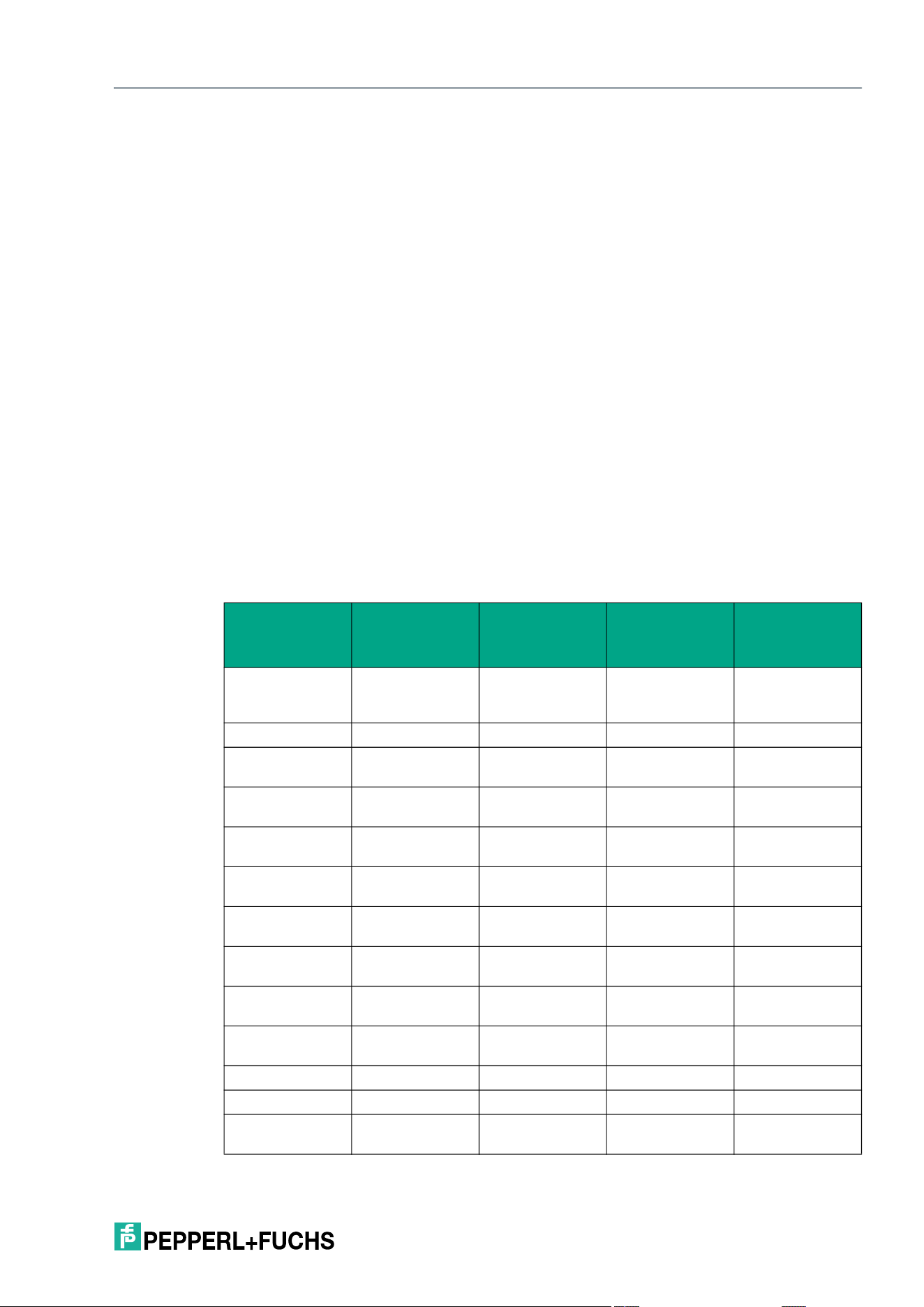
5.6 Ambient Temperature Range
The ambient temperature at which the devices can be operated depends on various factors,
such as the operating mode and the selected transmitter radiated power.
By adjusting the operating mode or the transmitter radiated power (parameter PT), the devices
can operate permanently at higher ambient temperatures, because the self-heating of the
devices is reduced.
Operation with transmission pauses
Continuous transmission operation
Continuous transmission operation, with forced convection
PT 1 2 3 4
IQT3-FP-IO-V1 -25 °C ... 70 °C
(-13 °F ... 158 °F)
-25 °C ... 70 °C
(-13 °F ... 158 °F)
-25 °C ... 70 °C
(-13 °F ... 158 °F)
-25 °C ... 70 °C
(-13 °F ... 158 °F)
IQT4-18GM-IO-V1 -25 °C ... 70 °C
(-13 °F ... 158 °F)
-25 °C ... 70 °C
(-13 °F ... 158 °F)
-25 °C ... 70 °C
(-13 °F ... 158 °F)
-25 °C ... 70 °C
(-13 °F ... 158 °F)
IQT4-F61-IO-V1 -25 °C ... 70 °C
(-13 °F ... 158 °F)
-25 °C ... 70 °C
(-13 °F ... 158 °F)
-25 °C ... 70 °C
(-13 °F ... 158 °F)
-25 °C ... 70 °C
(-13 °F ... 158 °F)
IQT4-FP-IO-V1 -25 °C ... 70 °C
(-13 °F ... 158 °F)
-25 °C ... 70 °C
(-13 °F ... 158 °F)
-25 °C ... 70 °C
(-13 °F ... 158 °F)
-25 °C ... 70 °C
(-13 °F ... 158 °F)
PT 1 2 3 4
IQT3-FP-IO-V1 -25 °C ... 70 °C
(-13 °F ... 158 °F)
-25 °C ... 70 °C
(-13 °F ... 158 °F)
-25 °C ... 65 °C
(-13 °F ... 149 °F)
-25 °C ... 55 °C
(-13 °F ... 131 °F)
IQT4-18GM-IO-V1 -25 °C ... 60 °C
(-13 °F ... 140 °F)
-25 °C ... 60 °C
(-13 °F ... 140 °F)
-25 °C ... 50 °C
(-13 °F ... 122 °F)
-25 °C ... 50 °C
(-13 °F ... 122 °F)
IQT4-F61-IO-V1 -25 °C ... 70 °C
(-13 °F ... 158 °F)
-25 °C ... 70 °C
(-13 °F ... 158 °F)
-25 °C ... 65 °C
(-13 °F ... 149 °F)
-25 °C ... 65 °C
(-13 °F ... 149 °F)
IQT4-FP-IO-V1 -25 °C ... 70 °C
(-13 °F ... 158 °F)
-25 °C ... 70 °C
(-13 °F ... 158 °F)
-25 °C ... 70 °C
(-13 °F ... 158 °F)
-25 °C ... 70 °C
(-13 °F ... 158 °F)
PT 1 2 3 4
IQT3-FP-IO-V1 -25 °C ... 70 °C
(-13 °F ... 140 °F)
-25 °C ... 70 °C
(-13 °F ... 158 °F)
-25 °C ... 70 °C
(-13 °F ... 158 °F)
-25 °C ... 70 °C
(-13 °F ... 158 °F)
IQT4-18GM-IO-V1 -25 °C ... 70 °C
(-13 °F ... 158 °F)
-25 °C ... 70 °C
(-13 °F ... 158 °F)
-25 °C ... 65 °C
(-13 °F ... 149 °F)
-25 °C ... 65 °C
(-13 °F ... 149 °F)
IQT4-F61-IO-V1 -25 °C ... 70 °C
(-13 °F ... 158 °F)
-25 °C ... 70 °C
(-13 °F ... 158 °F)
-25 °C ... 70 °C
(-13 °F ... 158 °F)
-25 °C ... 70 °C
(-13 °F ... 158 °F)
IQT4-FP-IO-V1 -25 °C ... 70 °C
(-13 °F ... 158 °F)
-25 °C ... 70 °C
(-13 °F ... 158 °F)
-25 °C ... 70 °C
(-13 °F ... 158 °F)
-25 °C ... 70 °C
(-13 °F ... 158 °F)
IQT3 / IQT4 Series
Commissioning and Operation
2026-05
27
6 Commissioning and Operation
6.1 Operating Modes
The device supports two operating modes:
• Easy mode
Easy mode enables simplified commissioning with a limited range of functions. This is the
preferred operating mode for standard applications.
• Expert mode
The entire set of commands is available in Expert mode. To use Expert mode, a function
block is required to integrate into the PLC.
6.2 Tag 13.56 MHz ISO15693
The tags of an RFID system with 13.56 MHz offer significantly quicker access to the data than a
comparable RFID system based on a working frequency of 125 kHz. The 13.56 MHz system is
standardized through ISO15693. A variety of tags from different manufacturers using different
RFID chips is supported.
Parameterization of the associated tag type is recommended to set the RFID read/write device
to the tag being used. On delivery of the RFID read/write device, tag type 20 is preset. This set-
ting guarantees access to the fixed code of ISO15693-compliant tags.
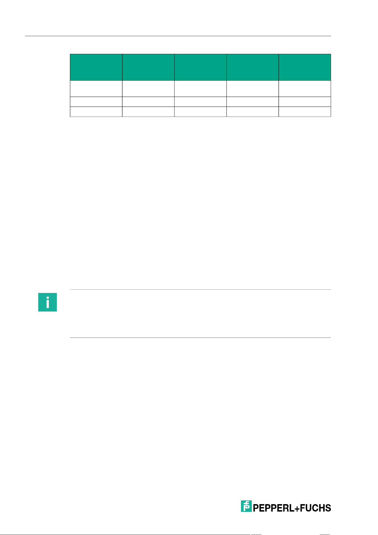
The following table shows the tag types specified and recommended for the RFID read/write
device.
13.56 MHz/ISO 15693 tag types
Pepperl+Fuchs
designation
Chip type Manufacturer
Size of
read/write mem-
ory [byte]
Size of memory
block [byte]
IQC20 All tags in accor-
dance with
ISO15693
- Depending on the
tag
Depending on the
tag
IQC21 I-Code SLI(X) NXP 112 4
IQC22 Tag-it HF-I Plus Texas Instru-
ments
256 4
IQC23 my-D
SRF55V02P
Infineon 224 4
IQC24 my-D
SRF55V10P
Infineon 992 4
IQC27 EM4135 EM Microelec-
tronic
288 8
IQC31 Tag-it HFI stan-
dard
Texas Instru-
ments
32 4
IQC32 Tag-it HFI pro Texas Instru-
ments
32 4
IQC33 FRAM
MB89R118
Fujitsu 2000 8
IQC34 FRAM
MB89R119
Fujitsu 232 4
IQC35 I-Code SLI-S NXP 160 4
IQC36 I-Code SLI-L NXP 32 4
IQC37 FRAM
MB89R112
Fujitsu 8192 32
2026-05
28
IQT3 / IQT4 Series
Commissioning and Operation
All ISO15693-compliant tags have a unique 8-byte fixed code. The fixed code is determined by
the chip manufacturer. The user can only read it and it cannot be changed. In addition, the tags
have a memory area for user data. This can be written with application-specific data and read.
The size of the memory for the user data differs according to the tag type.
The memory is divided into blocks with a length of 4 bytes. There are also exceptions with a
block length of 8 bytes or 32 bytes. As a result of the block length of 32 bytes, Easy Mode does
not support tag type IQC37.
The read and write commands use the "Number bytes" and "Start address" parameters. This
defines how many bytes are accessed in the memory area of the user data and from which
memory address this starts. If the tag type used has a block length of 4 bytes, the values of the
"Number of bytes" and "Start address" parameters must be a multiple of 4. In the case of a
block length of 8 or 32 bytes, they are multiples of 8 or 32.
6.3 Sensing Range
IQT3 Series
The read/write device is classified with a sensing range of up to 30 cm. The range of the device
depends on the tags to be identified and may therefore vary. You can change the transmitter
radiated power (parameter PT) to enlarge or reduce the size of the sensing range.
IQT4 Series
The read/write devices are classified with a sensing range of up to 20 cm. The range of the
devices varies depending on the design and is dependent on the tags to be identified. You can
change the transmitter radiated power (parameter PT) to enlarge or reduce the size of the
sensing range.
IQC38 EM4233 EM Microelec-
tronic
208 4
IQC50 I-Code SLIX2 NXP 316 4
IQC51 I-Code 3 NXP 300 4
Table 6.1 13.56 MHz tag types in accordance with ISO 15693
Pepperl+Fuchs
designation
Chip type Manufacturer
Size of
read/write mem-
ory [byte]
Size of memory
block [byte]
Note
To comply with the limit value of the magnetic field strength of max. 10 A/m in accordance with
ISO 15693-1, a minimum distance of 50 mm must be maintained between the tag and the
read/write device at a transmitter radiated power PT > 1. Otherwise, there is a risk that a tag will
be damaged in the near range. Reduce the transmitter radiated power of the read/write device
to PT = 1 to meet the limit value at small minimum distances.

IQT3 / IQT4 Series
Commissioning and Operation
2026-05
29
6.4 Multiple Tags in Sensing Range
The behavior when identifying tags in the sensing range depends on the operating mode
selected.
Easy Mode
All detected tags are transmitted. Filtering for individual tags is not possible.
Expert Mode
Each read or write command can access one, several, or all tags in the sensing range. Filter
masks that are managed with the TI parameter are used for control. These commands allow
you to detect specific tags in the sensing range. See "Tag ID Filter (TI)" on page 136.
In addition, selective read/write commands can be used to execute specific commands for indi-
vidual tags.
Note
For multi-tag applications, use the same tag types.
For multi-tag operation, the "Input Representation" IO-Link parameter must be set to "Long-
Form."
2026-05
30
IQT3 / IQT4 Series
Easy Mode
7 Easy Mode
The RFID read/write device uses the "Easy Mode" communication protocol on the basis of IO-
Link for data transfer to a higher-level system. If this protocol is used, the RFID read/write
device can be commissioned without an additional function block on a control system. This
makes it easier to commission the read/write device.
When "Easy Mode" is used, there is a distinction between parameter and process data. The
parameter data is IO-Link parameters being transferred acyclically. This is data for the configu-
ration of the read/write jobs, for parameterizing the device properties, e.g., transmit power and
service data, e.g., operating hours meter. The process data is transmitted in cycles. The pro-
cess data is divided into input and output data. It has a length of 32 bytes and contains the con-
trol values for the execution of the read and write commands and the associated values.
The IO-Link parameters for setting the RFID read/write device are defined by a device-specific
IODD file. The IO-Link parameters are set using suitable configuration software. During this
process, the IO-Link parameters are saved in a non-volatile memory in the RFID read/write
device.
7.1 Command Overview
The Easy Mode supports the following read and write commands:
7.2 Basic Structure of the Process Data
The device process data is exchanged cyclically between a higher-level system (e.g., a PLC)
and the device. A distinction is made between the output process data and the input process
data. The process data for the outputs is transmitted from the PLC toward the device. The pro-
cess data for the inputs is transmitted from the device toward the PLC.
A detailed description of the process data can be found in the IODD or on the IO-Link parame-
ter datasheet of the device. You can find the IODD and the parameter datasheet on the product
details page at www.pepperl-fuchs.com.
The input and output data of the process data have a fixed length of 32 bytes.
Command Description
Read the read-
only code (UID)
Read-out of the 8 byte read-only code; no setting of the "Number of bytes"
or "Start Address" parameters required
Read the user
memory
Read-out of user data; setting of the "Number of bytes" and "Start Address"
parameters is required
Write the user
memory
Writing of user data; setting of the "Number of bytes" and "Start Address"
parameters is required
Auto-start Automatic execution of a read task for read-only code or user data after
device start
Note
Output process data is ignored by the device if the "valid" flag is not set. An unset "valid" flag
indicates invalid process data.
IQT3 / IQT4 Series
Easy Mode
2026-05
31
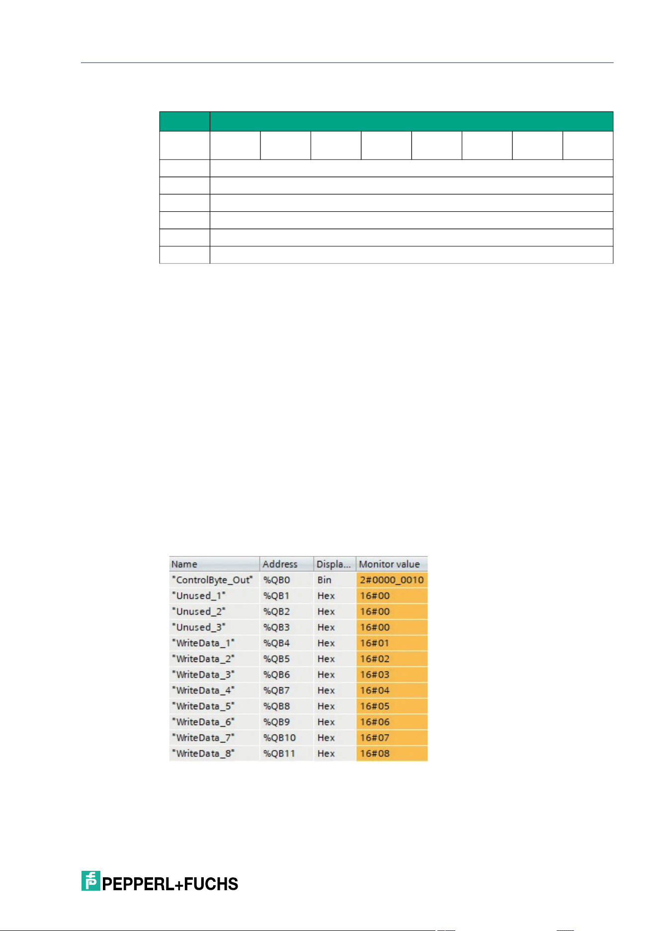
7.2.1 Output Process Data (PLC -> Device)
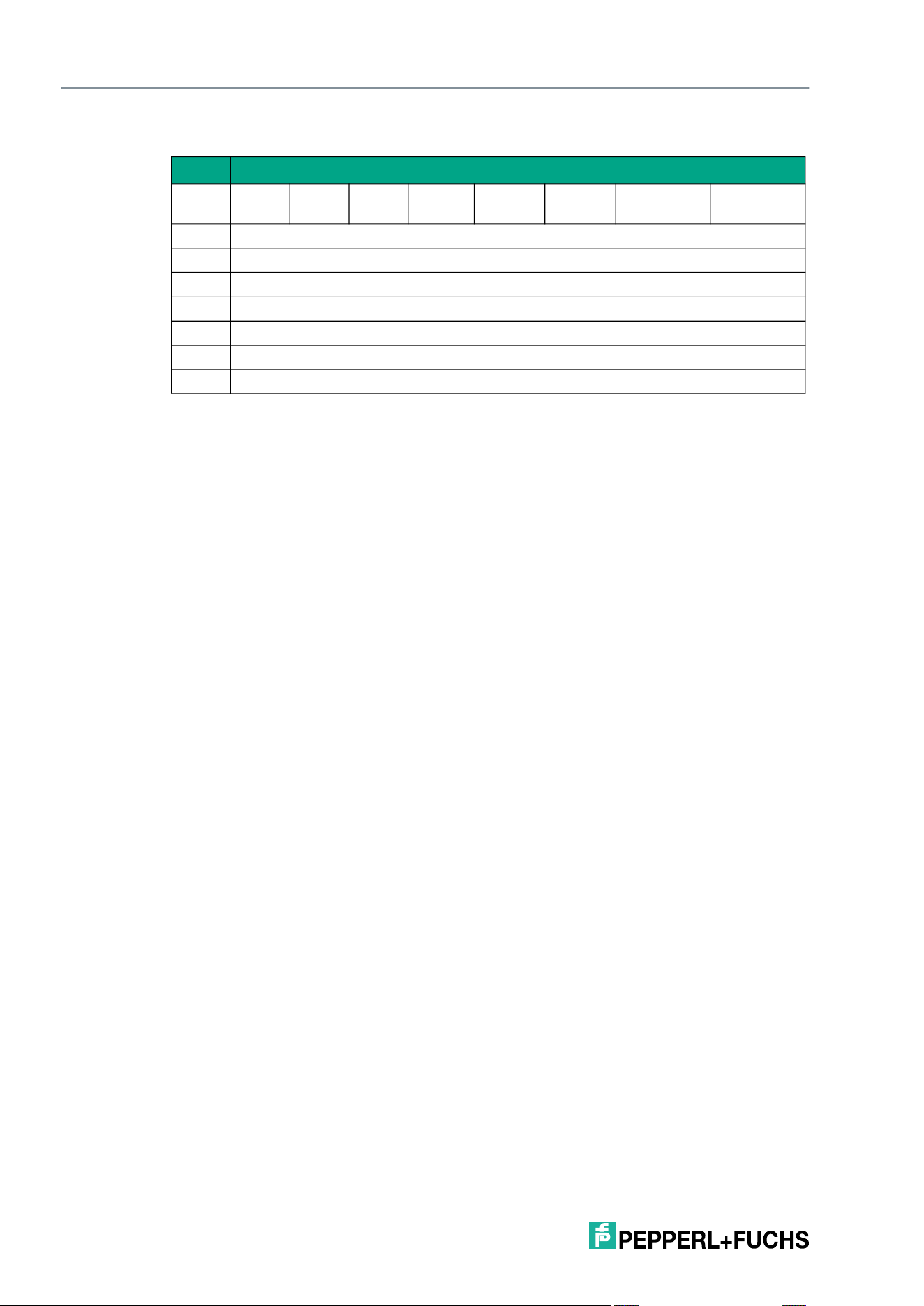
For example: Writing user memory in TIA Portal
Byte Content
0 0 0 0 0 0 0 Start
write
Start
read
1 0x00
2 0x00
3 0x00
4 User data for write job or 16#00 for read job
... User data for write job or 16#00 for read job
31 User data for write job or 16#00 for read job
Table 7.1
Byte 0 This byte contains the control bits for starting a read job or write job. If the auto-
start function is enabled, the control bits have no effect.
Start Read: As soon as this bit is set (TRUE), a read job is started using the
configuration set by the parameter "Read Task" in the IODD file. The read job
is executed continuously. To cancel the read job, reset the bit (FALSE).
Start Write: As soon as this bit is set (TRUE), a write job is started. The write
job transfers the user data, which must be stored starting from byte 4, according
to the configuration set by the parameter "Write Task" in the IODD file. The write
job is executed continuously. To cancel the write job, reset the bit (FALSE).
Note that both bits must not be set at the same time. The remaining bits have
no function.
Byte 1/2/3 These bytes are not used in Easy Mode. Set the value 0x00.
Byte 4 … 31 When a read job is being executed, these bytes have no significance and are
set with the value 0x00. When a write job is being executed, this area contains
the user data to be written to the tag.
Output Process Data
Byte 0: 0000 0010
bin
; the "Start
write" bit is set to 1; a write job is
executed.
Byte 1/2/3: 16#00; not used
Byte 4 … Byte 11: Write data
2026-05
32
IQT3 / IQT4 Series
Easy Mode
7.2.2 Input Process Data (Device -> PLC)
Byte Content
0 0 0 0 Tag
present
Error Job
active
Write
successful
Read
successful
1 Length specification
2 RSSI value
3 Reserved
4 Data for read/write job / error code
5 Data for read/write job / error information
... Data for read/write job / error information
31 Data for read/write job / error information
Table 7.2
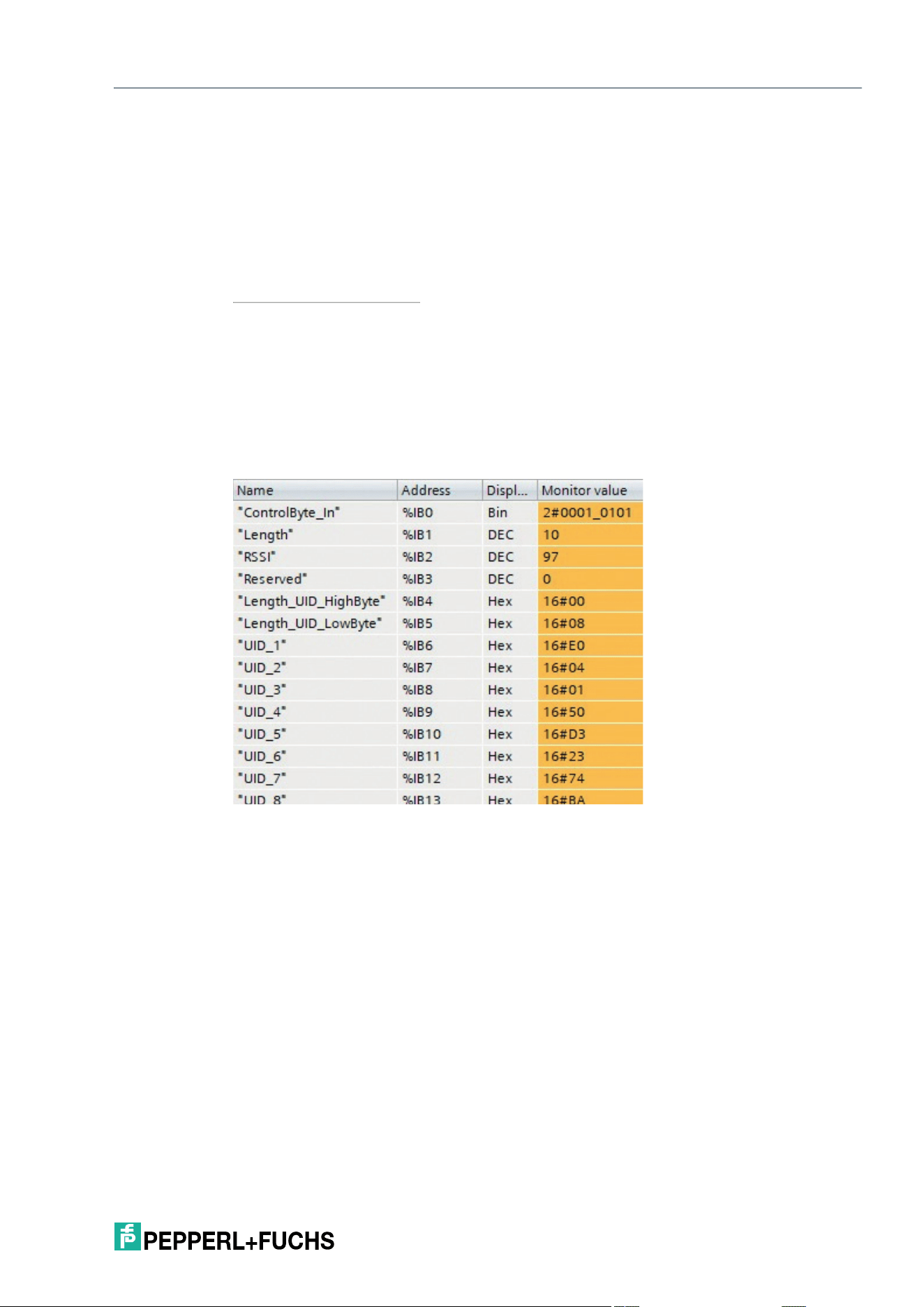
Byte 0 This byte contains the control bits for signaling the execution status of the
read or write job.
Read successful: This bit signals that data was read from a tag success-
fully. This bit is set if a tag enters the sensing range and the data has been
read successfully. The bit remains set while the tag is within the sensing
range. As soon as the tag leaves this area, the bit is reset. If multiple tags
are within the sensing range at the same time, a positive edge change sig-
nals that another tag is
1
being transmitted.
Write successful: This bit signals that data was written to a tag success-
fully. This bit is set if a tag enters the sensing range and the data has been
written successfully. The bit remains set while the tag is within the sensing
range. As soon as the tag leaves this area, the bit is reset. If multiple tags
are present simultaneously within the sensing range, a positive edge indi-
cates that another tag was written to successfully.
Job active: This bit is set while the read or write job is being executed. As
soon as the job is complete, the bit is reset.
Error: If an error occurs during execution of a read or write job, or if a pa-
rameter setting is incorrect, this is signaled by this bit. At the same time, ad-
ditional error information in the form of an error code is located in the
process data.
Tag present: Bit is set if one or more tags are in the sensing range. If there
is no tag in the sensing range, this bit has the value FALSE.
Byte 1 This byte contains the number of transferred bytes. If a tag enters the sens-
ing range and the data has been read successfully (Read successful =
TRUE), this byte indicates the length of the read data. If an error occurs
during execution of a job (Error = TRUE), this byte contains a length spec-
ification for the error information.
Byte 2 The RSSI value indicates the signal strength of the tag response as a per-
centage. The value range is between 0 and 100. 0 % = weak signal, 100 %
= strong signal.
Byte 3 Reserved.
IQT3 / IQT4 Series
Easy Mode
2026-05
33
If an error occurs during execution of a read or write job ("Error" bit = TRUE), byte 4 contains an
error code. In the fault state, an error message is transmitted in plain text (ASCII) starting at byte
5. This provides a possible cause of fault.
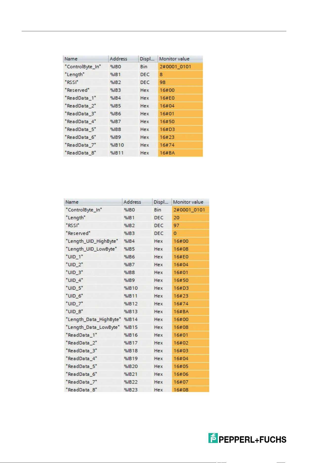
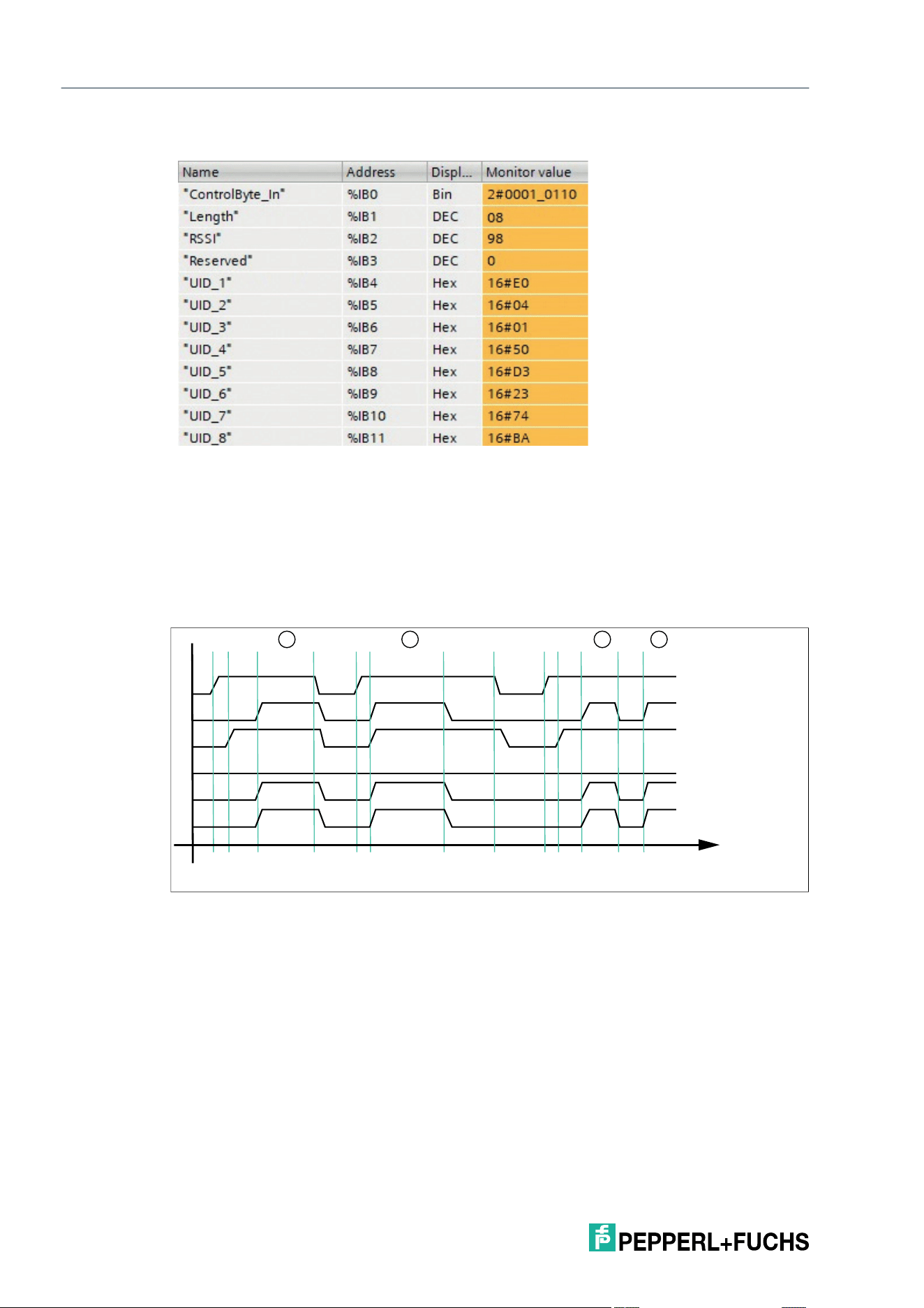
For example: Read fixed code (UID), long-form data format
Byte 4/5 If a tag is successfully accessed, the length of the fixed code UID is located
at this position.
2
Byte 6 … Byte 31 Starting at byte 6, the UID of the tag from which the information was read
or to which the information was written is transmitted. The UID is always in-
cluded in the response to a read or write job. This information ensures
unique assignment of the tag. When a user memory read job is performed,
the length specification (2 bytes) of the read-in user memory and the read-
in subarea of the user memory are connected.
1.Positive edge change: Change from 0 to 1
2.Applies only to the long-form data format. In the short-form data format, the UID or the user memory of the tag is
transferred directly from byte 4.
Byte 0: 0001 0101
bin
; the "Job
active" bit is set to 1, which
indicates that a read job is
activated. The "Read suc-
cessful" bit is set to 1. A tag is
therefore located in the sens-
ing range and the data has
been read. In addition, the
"Tag present" bit is set
because there is at least one
tag in the sensing zone.
Byte 1: 10; the byte indicates
the length of the transmitted
information. This telegram is
used to transmit information
with a length of 10 bytes. The
information starts at byte 4.
Byte 2: 97; RSSI value
Byte 3: 0; Reserved
Byte 4/5: 16#0008; length
specification of the UID. The
information has a length of 2
bytes. The length of the UID is
always 8 bytes.
Byte 8 … Byte 13: UID of the
tag that was read
2026-05
34
IQT3 / IQT4 Series
Easy Mode
For example: Read fixed code (UID), short-form data format
For example: Read user memory, long form data format
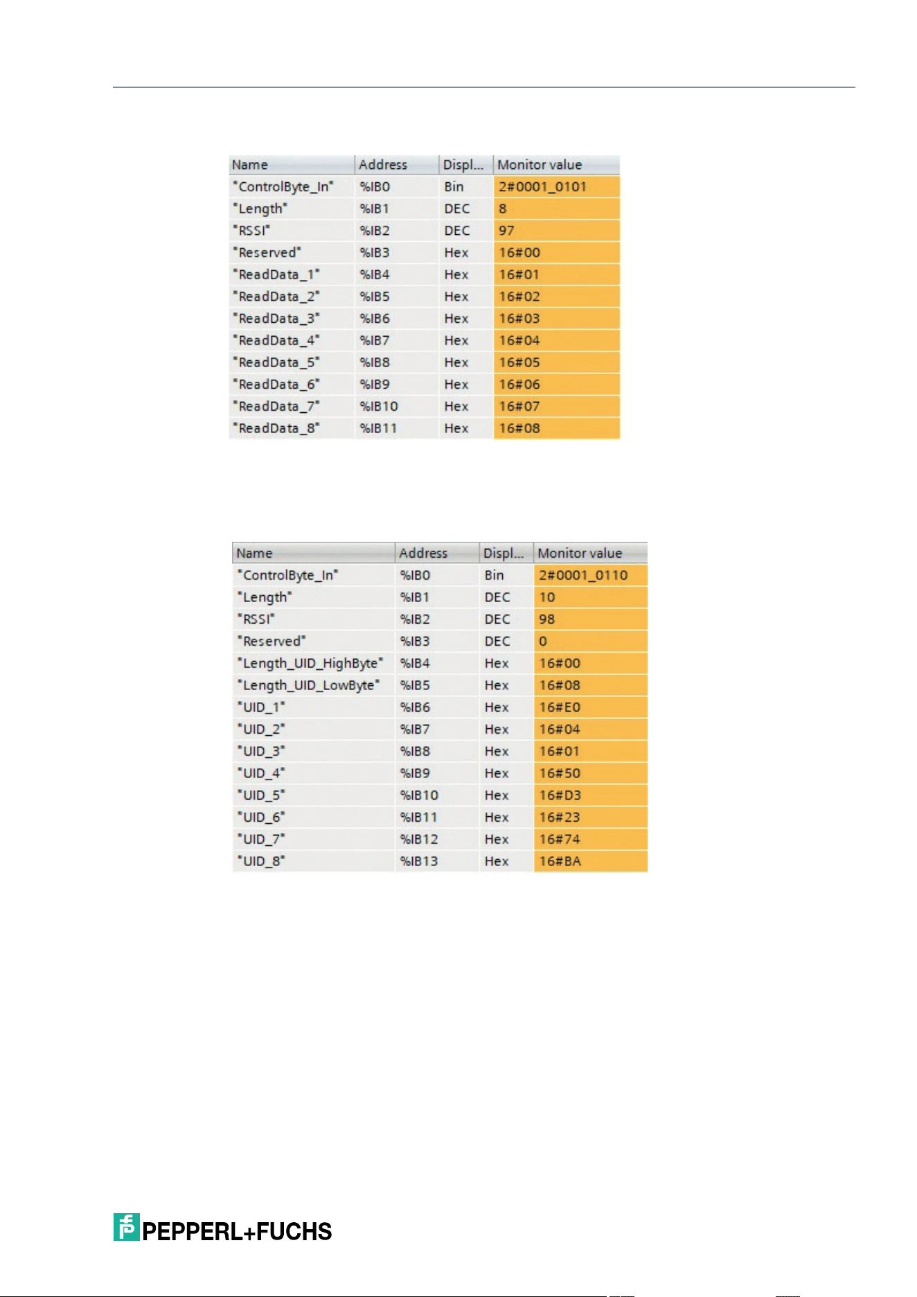
Byte 0: 0001 0101
bin
; the "Job
active" bit is set to 1, which indi-
cates that a read job is acti-
vated. The "Read successful" bit
is set to 1. A tag is therefore
located in the sensing range and
the data has been read. In addi-
tion, the "Tag present" bit is set
because there is at least one tag
in the sensing zone.
Byte 1: 8; the byte indicates the
length of the transmitted infor-
mation. This telegram is used to
transmit information with a
length of 8 bytes. The informa-
tion starts at byte 4.
Byte 2: 98; RSSI value
Byte 3: 16#00; reserved
Byte 4 … Byte 11: UID of the tag
that was read.
Byte 0: 0001 0101
bin
; The
"Job active" bit is set to 1 and
signals an active read job.
The "Read successful" bit is
set to 1. A tag is located in the
sensing range and the data
has been read. In addition,
the "Tag present" bit is set
because there is at least one
tag in the sensing zone.
Byte 1: 20; the byte indicates
the length of the transmitted
information. This telegram is
used to transmit information
with a length of 20 bytes. The
information starts at byte 4.
Byte 2: 97; RSSI value
Byte 3: 0; Reserved
Byte 4/5: 16#0008; length
specification of the UID. The
information has a length of 2
bytes. The length of the UID is
always 8 bytes.
Byte 6 … Byte 13: UID of the
identified tag
Byte 14/15: 16#0008; length
specification for the read-in
user memory
Byte 16 … Byte 23: User
memory section read
IQT3 / IQT4 Series
Easy Mode
2026-05
35
For example: Read user memory, short-form data format
For example: Write user memory, long form data format
Byte 0: 0001 0101
bin
; The "Job
active" bit is set to 1 and signals
an active read job. The "Read
successful" bit is set to 1. A tag is
located in the sensing range and
the data has been read. In addi-
tion, the "Tag present" bit is set
because there is at least one tag
in the sensing zone.
Byte 1: 8; the byte indicates the
length of the transmitted informa-
tion. This telegram is used to
transmit information with a length
of 8 bytes. The information starts
at byte 4.
Byte 2: 97; RSSI value
Byte 3: 16#00; reserved
Byte 4 … Byte 11: User memory
section read
Byte 0: 0001 0110
bin
; The
"Job active" bit is set to 1
and signals an active write
job. The "Write successful"
bit is set to 1. A tag is located
in the sensing range and the
data has been written suc-
cessfully. In addition, the
"Tag present" bit is set
because there is at least one
tag in the sensing range.
Byte 1: 10; the byte indicates
the length of the transmitted
information. This telegram is
used to transmit information
with a length of 10 bytes.
The information starts at
byte 4.
Byte 2: 98; RSSI value
Byte 3: 0; Reserved
Byte 4/5:16#0008; length
specification of the UID. The
information has a length of 2
bytes. The length of the UID
is always 8 bytes.
Byte 6 … Byte 13: UID of the
tag to which the data was
written.
2026-05
36
IQT3 / IQT4 Series
Easy Mode
For example: Write user memory, short-form data format
7.2.3 Flowcharts
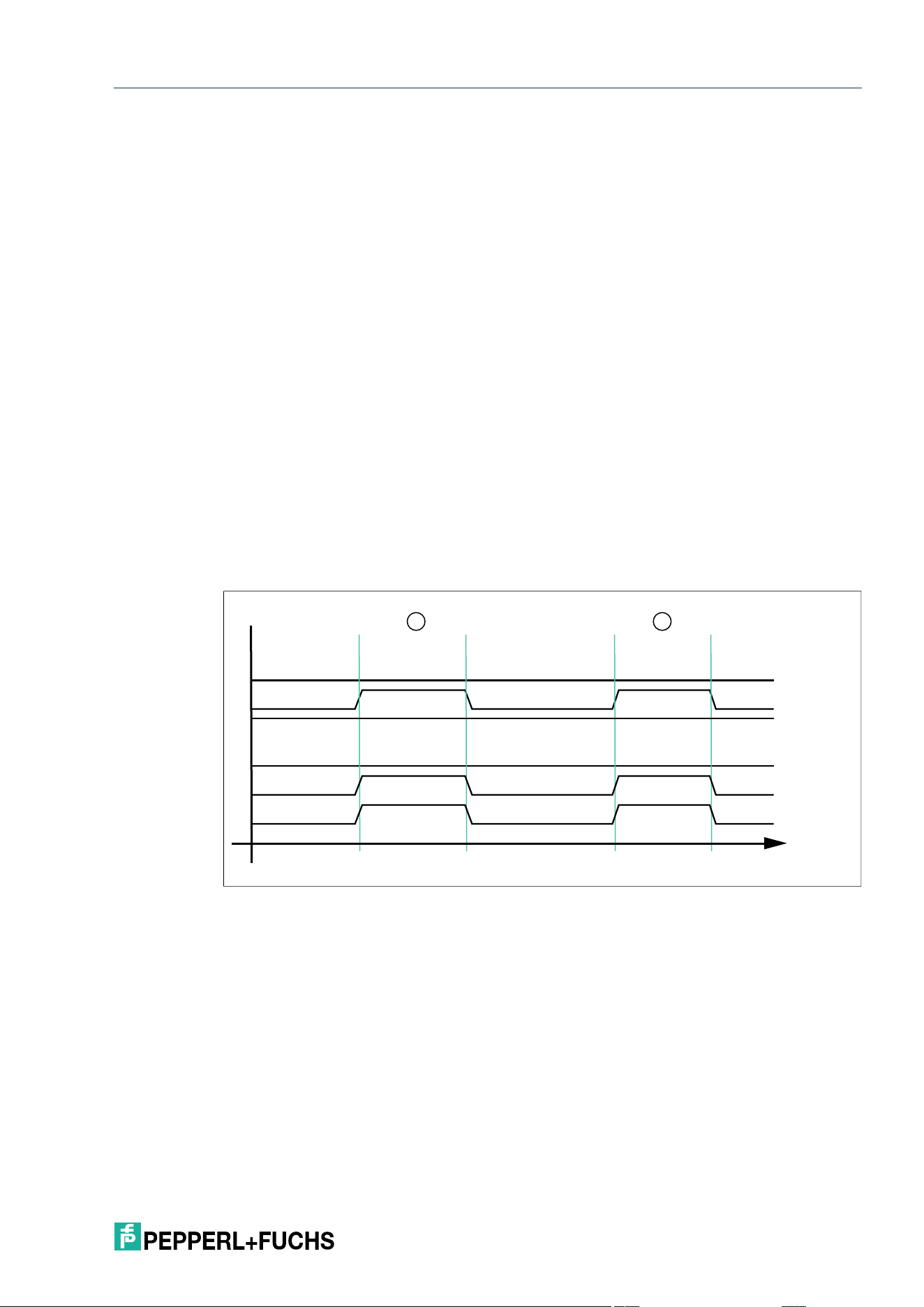
Read Job Without Autostart Function
Figure 7.1 Timing sequence of bits in byte 0
If the auto-start function is not used, the read job is started with the "Start read" bit. The read job
is performed until the "Start read" bit is reset to FALSE.
T1: Start of the read job by setting the "Start read" bit to TRUE
T2: The read job is executed and indicated by the "Job active" bit ("Job active" = TRUE)
Byte 0: 0001 0110
bin
; The
"Job active" bit is set to 1 and
signals an active write job.
The "Write successful" bit is
set to 1. A tag is located in the
sensing range and the data
has been written successfully.
In addition, the "Tag present"
bit is set because there is at
least one tag in the sensing
zone.
Byte 1: 8; the byte indicates
the length of the transmitted
information. This telegram is
used to transmit information
with a length of 8 bytes. The
information starts at byte 4.
Byte 2: 98; RSSI value
Byte 3: 0; Reserved
Byte 4 … Byte 11: UID of the
tag to which the data was writ-
ten.
1 Start read
2 Read successful
3 Job active
4 Error
5 Tag present
6 Data (input)
T1
T2
T3 T4 T5T6 T7
B
A
C
D
6
4
5
3
2
1
T8
T9T10T11 T12 T13
t
IQT3 / IQT4 Series
Easy Mode
2026-05
37
T3: Tag A enters the sensing range; "Read successful" and "Tag present" are set to TRUE and
the read data is located in the input field of the process data
T4: Read job is canceled by resetting the "Start read" bit to FALSE while the tag is located in the
sensing range; the "Job active" bit, the "Read successful" bit and the "Tag present" are set to
FALSE and the process data is filled with 0x00
T5: Start of the read job by setting the "Start read" bit to TRUE; at the time of the start, a tag B is
already located in the sensing range
T6: Read job is being executed ("Job active" = TRUE) and the data is read successfully ("Read
successful" and "Tag present" = TRUE); the read data is located in the input field of the process
data
T7: Tag leaves the sensing range ("Read successful" and "Tag present" = FALSE); the area of
the input field with the read process data is set to the value 0x00
T8: Cancellation of the read job ("Start read" = FALSE); the "Job active" bit is reset
T9: Start of the read job by setting the "Start read" bit to TRUE; at the time of the start, no tag is
located in the sensing range; read job remains permanently active
T10: The read job is executed ("Job active" = TRUE).
T11: Tag C enters the sensing range and the data is read ("Read successful" and "Tag present"
= TRUE); read data is located in the input field of the process data
T12: Tag C leaves the sensing range ("Read successful" and "Tag present" = FALSE)
T13: Tag D enters the sensing range
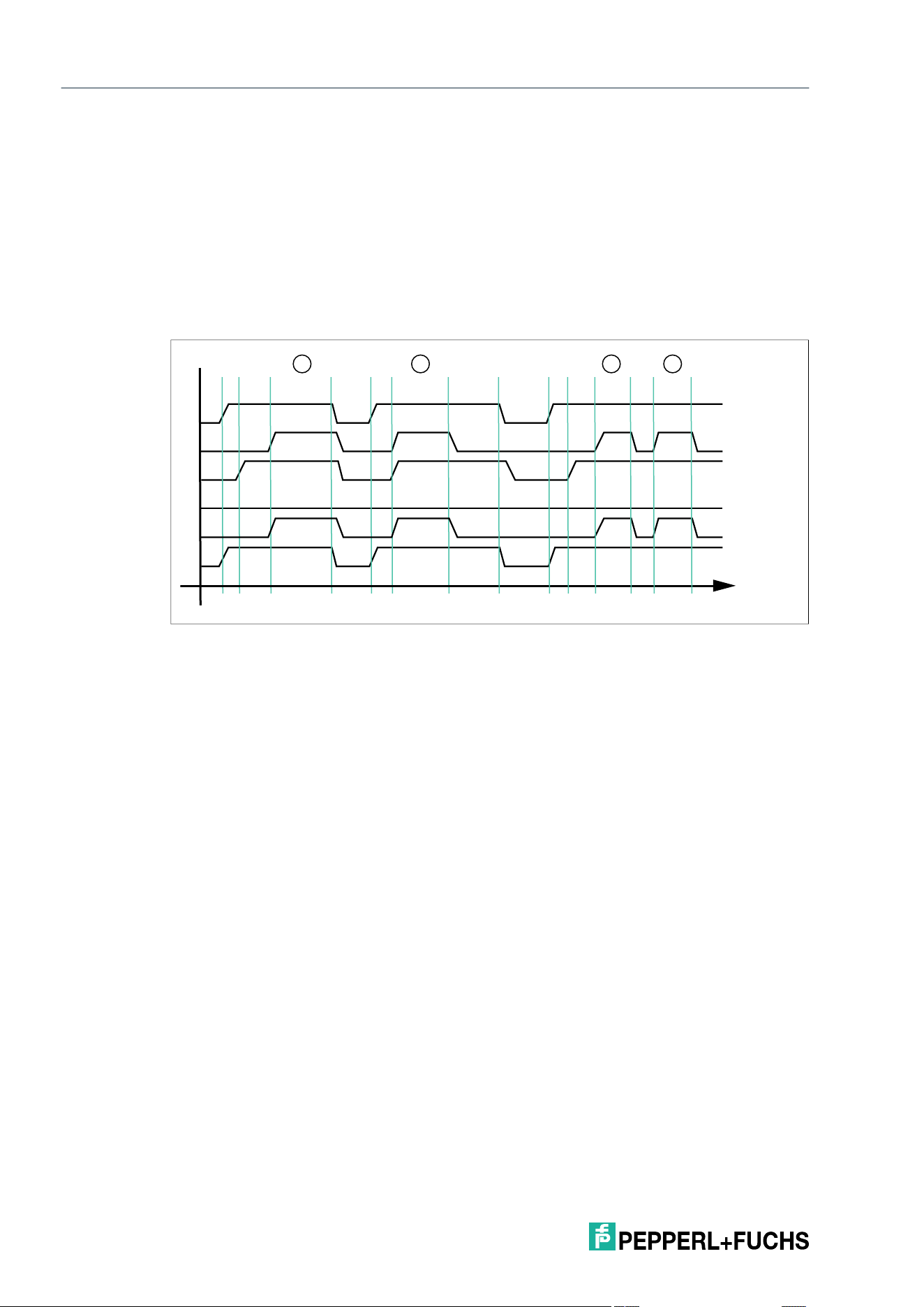
Read Job With Autostart Function
Figure 7.2 Timing sequence of bits in byte 0
1 Start read
2 Read successful
3 Job active
4 Error
5 Tag present
6 Data (input)
T1
T2
T3 T4
B
A
6
4
3
2
5
1
t
2026-05
38
IQT3 / IQT4 Series
Easy Mode
With the autostart function, read access is performed continuously, and the "Job active" bit of
the input process data is set continuously.
T1: Tag A enters the sensing range; "Read successful" and "Tag present" are set to TRUE and
the read data is located in the input field of the process data
T2: Tag A leaves the sensing range; "Read successful" and "Tag present" are reset to FALSE;
the area with the previously read data is filled with 0x00
T3: Tag B enters the sensing range; behavior same as T1
T4: Tag B leaves the sensing range; behavior same as T2
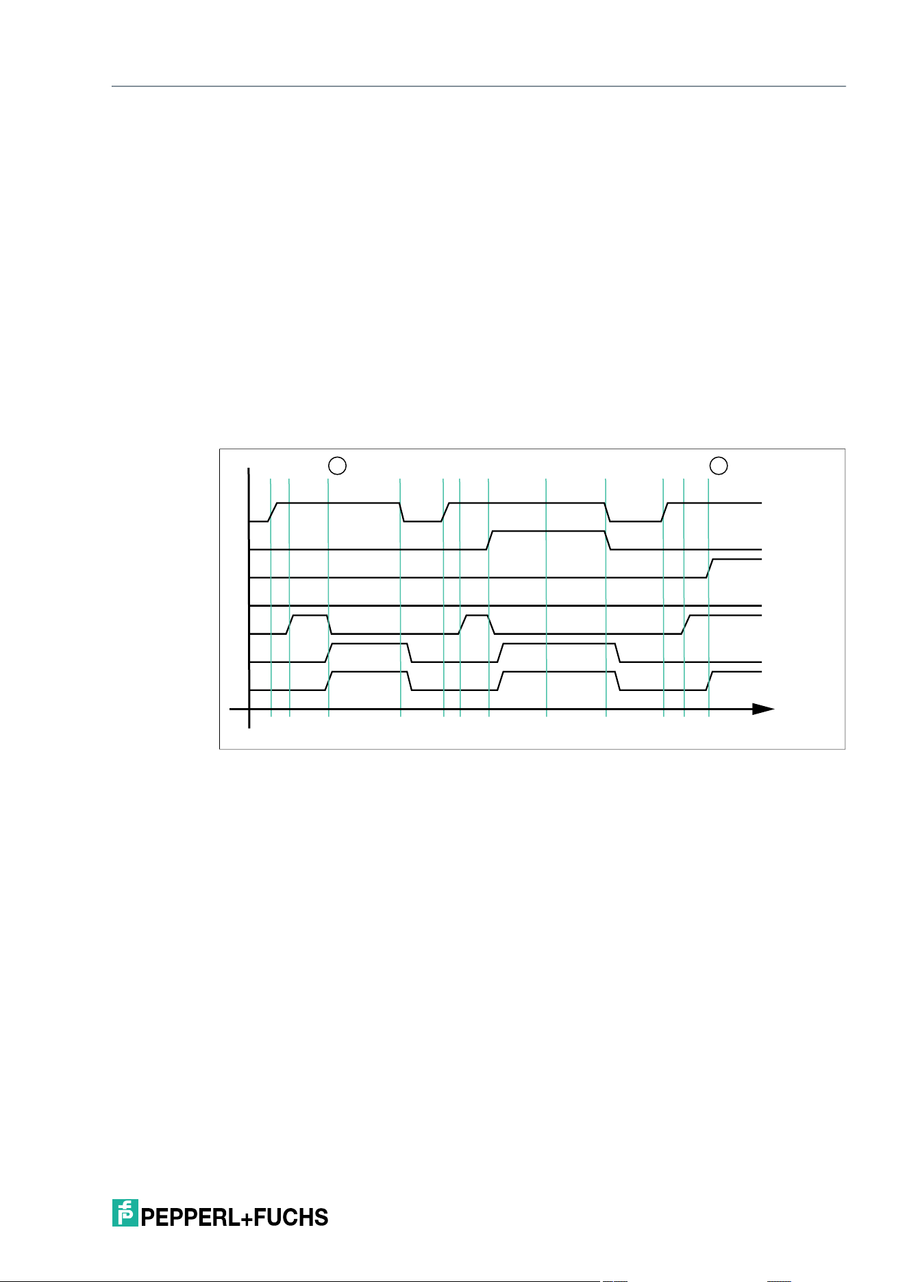
Write Job
Figure 7.3 Timing sequence of bits in byte 0
Execution of a write job cannot be performed via the autostart function. To start a write job, set
the "Start write" bit to TRUE.
T1: Start of the write job by setting the "Start write" bit to TRUE; at the same time, the user data
to be written to the tag must be transferred to the output field of the process data.
T2: Write job is active ("Job active" = TRUE), and no tag is located in the sensing range ("Write
successful" = FALSE)
T3: Tag A enters the sensing range and the data is written successfully ("Write successful" and
"Tag present" = TRUE)
T4: The write job is canceled by resetting the "Start write" bit to FALSE; the "Job active," "Write
successful" and "Tag present" bits are reset to FALSE and the usable data is reset by the user
to the value 0x00
T5: The write job is started by setting the "Start write" bit to TRUE and at the same time transfer-
ring the data to be written to the output field of the process data; at the time of the start, tag B is
located in the sensing range
T6: The write job is active ("Job active" = TRUE) and tag B is described successfully ("Write
successful" and "Tag present" = TRUE)
T7: Tag B leaves the sensing range ("Write successful" and "Tag present" = FALSE); the write
job remains active ("Job active" = TRUE)
1 Start write
2 Write successful
3 Job active
4 Error
5 Tag present
6 Data (input)
T1
T2
T3 T4 T5 T6 T7
B
A
C
D
6
4
3
2
5
1
T8
T9 T10 T11 T12T13 T14
t
IQT3 / IQT4 Series
Easy Mode
2026-05
39
T8: The write job is canceled by resetting the "Start write" bit to FALSE; the "Job active," "Write
successful" and "Tag present" bits are reset to FALSE and the usable data is reset by the user
to the value 0x00
T9: Start of write job by setting the "Start write" bit to TRUE; at the same time, the user data to
be written to the tag is transferred to the output field of the process data.
T10: Write job is active ("Job active" = TRUE), and no tag is located in the sensing range
("Write successful" = FALSE)
T11: Tag C enters the sensing range and the data is successfully written ("Write successful"
and "Tag present" = TRUE); write job is still active ("Job active" = TRUE)
T12: Tag C leaves the sensing range ("Write successful" and "Tag present" = FALSE); write job
is still active ("Job active" = TRUE)
T13: Tag D enters the sensing range and the data is successfully written ("Write successful"
and "Tag present" = TRUE); write job is still active ("Job active" = TRUE)
T14: Tag D leaves the sensing zone ("Read successful" and "Tag present" = FALSE)
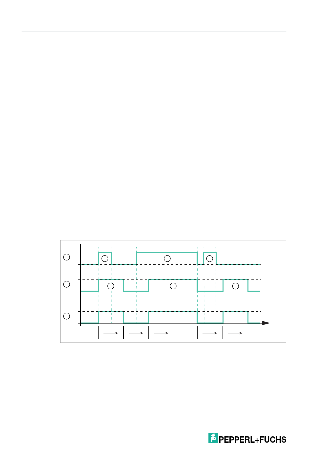
Fault State
If an error occurs during execution of a read or write job, this condition is signaled by the "Error"
bit. At the same time. an error message is transmitted in the input process data.
T1: Start of the read job by setting the "Start read" bit to TRUE
T2: The read job is active and is being executed ("Job active" = TRUE).
T3: Tag A with 4 bytes of memory enters the sensing range and the "Error" bit is set to TRUE.
The "Job active" bit is reset to FALSE and at the same time the error code 0x04 and the text
"invalid command" are entered in the input process data. This indicates that the read job set by
the IODD file is not suitable for the properties of the tag. The cause is the number of bytes to be
read. A maximum of 4 bytes can be read to access the tag. In this example, the value is set to 8.
To rectify the error, correct the value in the IODD file.
1 Start read
2 Start write
3 Read successful
4 Write successful
5 Job active
6 Error
7 Data (input)
t
T1 T2 T3 T4 T5T6 T7 T8 T9 T10T11T12
7
6
5
4
3
2
1
B
A
2026-05
40
IQT3 / IQT4 Series
Easy Mode
T4: The read job is canceled by resetting the "Start read" bit to FALSE; at the same time, the
"Error" bit is reset to FALSE and the error message in the input data is deleted
T5: Start of a new read job by setting the "Start read" bit to TRUE
T6: The read job is active and is being executed ("Job active" = TRUE).
T7: In addition, a write job is started by setting the "Start write" bit to TRUE. The "Error" bit is set
and "Job active" is reset to FALSE. An error message with the error code 0x04 and the text
"read AND write set" is transmitted to the input field of the process data. This indicates that a
read and a write job were triggered simultaneously. This is not permitted for the device.
T8: The fault state remains active ("Error" = TRUE), because the "Start read" and "Start write"
bits are set
T9: The "Start read" and "Start write" bits are reset to FALSE; at the same time, the "Error" bit is
reset to FALSE and the error message is deleted in the input data
T10: Start of the read job by setting the "Start read" bit to TRUE
T11: The read job is active and is being executed ("Job active" = TRUE).
T12: A tag B enters the sensing range and is read successfully ("Read successful" = TRUE)
7.2.4 Timing
The device does not use the complex handshake procedure for data transmission in Easy
Mode. The telegrams are set in the input process data and remain there for a defined hold time.
The device cannot change the input process data within this hold time.
The hold time is ten times the set cycle time. The hold time is at least 40 ms long because the
shortest possible cycle time is 4 ms.
The device can generate a new telegram within the hold time if a new tag is read or a tag leaves
the sensing range. This telegram is only set in the input process data after the 40 ms have
elapsed. If no new telegram occurs within the hold time, the input process data remains
unchanged.
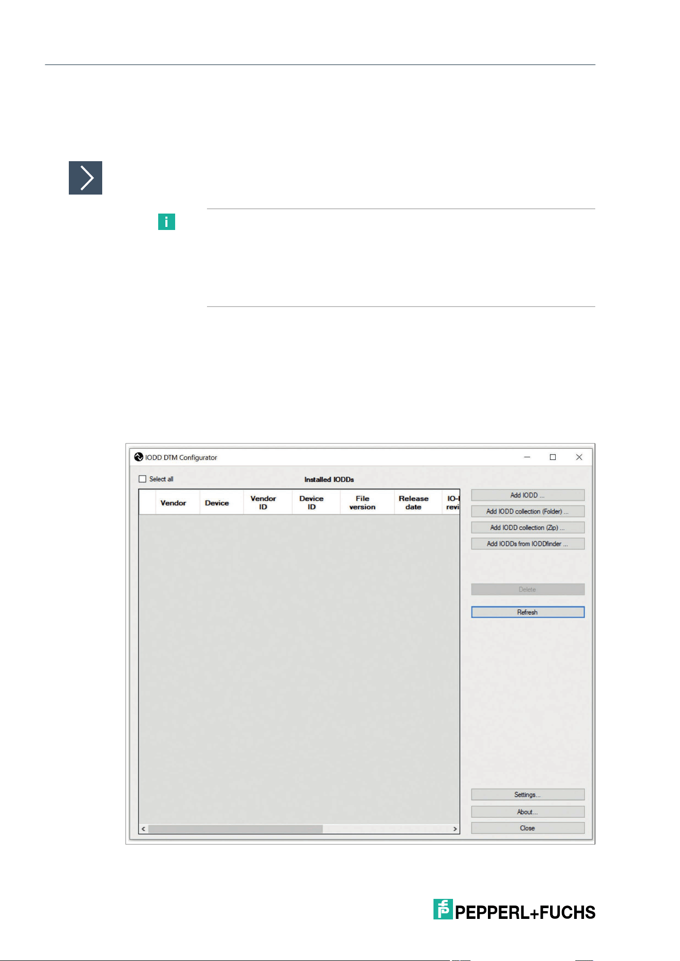
The diagram shows the fundamental chronological sequence of the data transmission depend-
ing on the presence of a tag within the device's sensing range.
"T
H
" corresponds to the minimum hold time of the device of 40 ms.
The device is activated via the auto-start function or the "Start read" bit. The device executes a
read job permanently.
1 Tag in the field
2 Data
3 Read successful
B
A
C
B
A
C
1
t
T
H
T
H
T
H
T
H
T
H
0
0
1
0
1
3
2
1

IQT3 / IQT4 Series
Easy Mode
2026-05
41
At the beginning, tag A enters the sensing range of the device and the "Read successful" bit in
the input process data changes the signal state to "TRUE" (1). The dwell time of the tag in the
sensing range is less than 40 ms, and it leaves shortly after entering. The input process data
containing information about tag A is retained for the time "T
H
" (= 40 ms). The input process
data is only updated again once this time span has expired. It contains the information "Read
successful" = FALSE (no tag) and indicates that the tag has left the sensing range. This tele-
gram remains in the input process data for the hold time of "T
H
."
Tag B enters the sensing range before the hold time of the previous telegram has elapsed. The
input process data is only updated once the hold time of 40 ms has expired, and the "Read suc-
cessful" bit then changes to "TRUE." The read-in data is simultaneously set in the input process
data. Tag B has a dwell time of more than 40 ms (> "T
H
") in the device's sensing range. During
this time span, the input process data remains unchanged and the "Read successful" bit con-
tinues to have the signal state "TRUE."
Tag B leaves the sensing range and the signal state of the "Read successful" bit changes
from 1 to 0 in the input process data. Before the hold time "T
H
" has elapsed, tag C enters the
sensing range. The input process data remains unchanged during the hold time span. It
changes the signal state of "Read successful" to "TRUE" once "T
H
" expires. This signals the
presence of tag C, and the read data of this tag is transmitted.
Tag C leaves the sensing range before the hold time "T
H
" has elapsed. Once the hold time of
the previous information has expired (tag B has left the sensing range), the input process data
is modified accordingly. The signal state of "Read successful" changes to "TRUE."
7.2.5 Interruption of IO-Link Communication
If IO-Link communication is interrupted, the device continues to operate normally. If a read job
is active at the time of cancellation, the received data is stored in the device. When the device
communicates via IO-Link again, this data is transferred to the IO-Link master.
Note
The device cache is designed for small amounts of data to compensate for short interruptions.
Data may be lost if IO-Link communication is interrupted for a long time.
2026-05
42
IQT3 / IQT4 Series
Easy Mode
7.3 Easy Mode with PACTware
You can commission the RFID read/write device using the IO-Link master "IO-Link-Master02-
USB."
Commissioning with PACTware
1.
Connect the RFID read/write device to the IO-Link master.
2. Connect the IO-Link master to a power supply.
3. Connect the IO-Link master to a PC using a USB cable.
4. Install the two software packages on your PC.
5. Install the IO-Link USB Master DTM 2.0 driver.
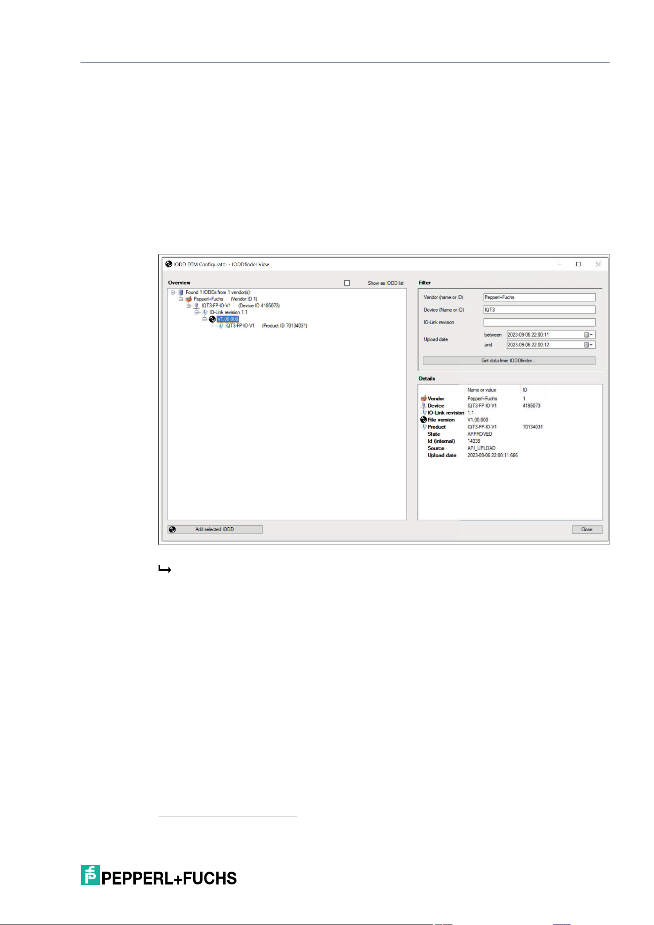
6. Import the IODD file for the RFID read/write device with the IODD DTM Configurator program.
Figure 7.4
Note
Use PACTware version 5.0 software to operate the system.
You can use the "IODD Interpreter DTM" software to integrate the IODD files
into the PACTware on a PC.
You can find the software, the IODD file and the driver on the Pepperl+Fuchs
homepage.
IQT3 / IQT4 Series
Easy Mode
2026-05
43
7. You can add IODDs using the IODDfinder in several ways:
• "Add IODD" adds a single IODD.
• "Add IODD Collection (Folder)" adds an entire folder that can contain multiple IODDs.
• "Add IODD Collection (*.zip)" adds an archived folder that can contain multiple IODDs.
1
• "Add IODD from IODDfinder" allows full access to the IODDfinder database ioddfinder.io-
link.com.
8. You can use the filter mask to narrow down the manufacturer and device. Enter
"Pepperl+Fuchs" as the manufacturer and "IQT3-FP-IO-V1" as the device.
9. Select the required IODD file version of the device (highlighted in blue)
10. Click "Add selected IODD."
Figure 7.5
Successfully added IODDs appear in "Installed IODDs."
1.For example IODD download from the Pepperl+Fuchs homepage

2026-05
44
IQT3 / IQT4 Series
Easy Mode
Figure 7.6
Close the IODD DTM Configurator program.
11. Start PACTware.
12. Right-click on the "HOST PC."
13. Select the "Add device" menu item.
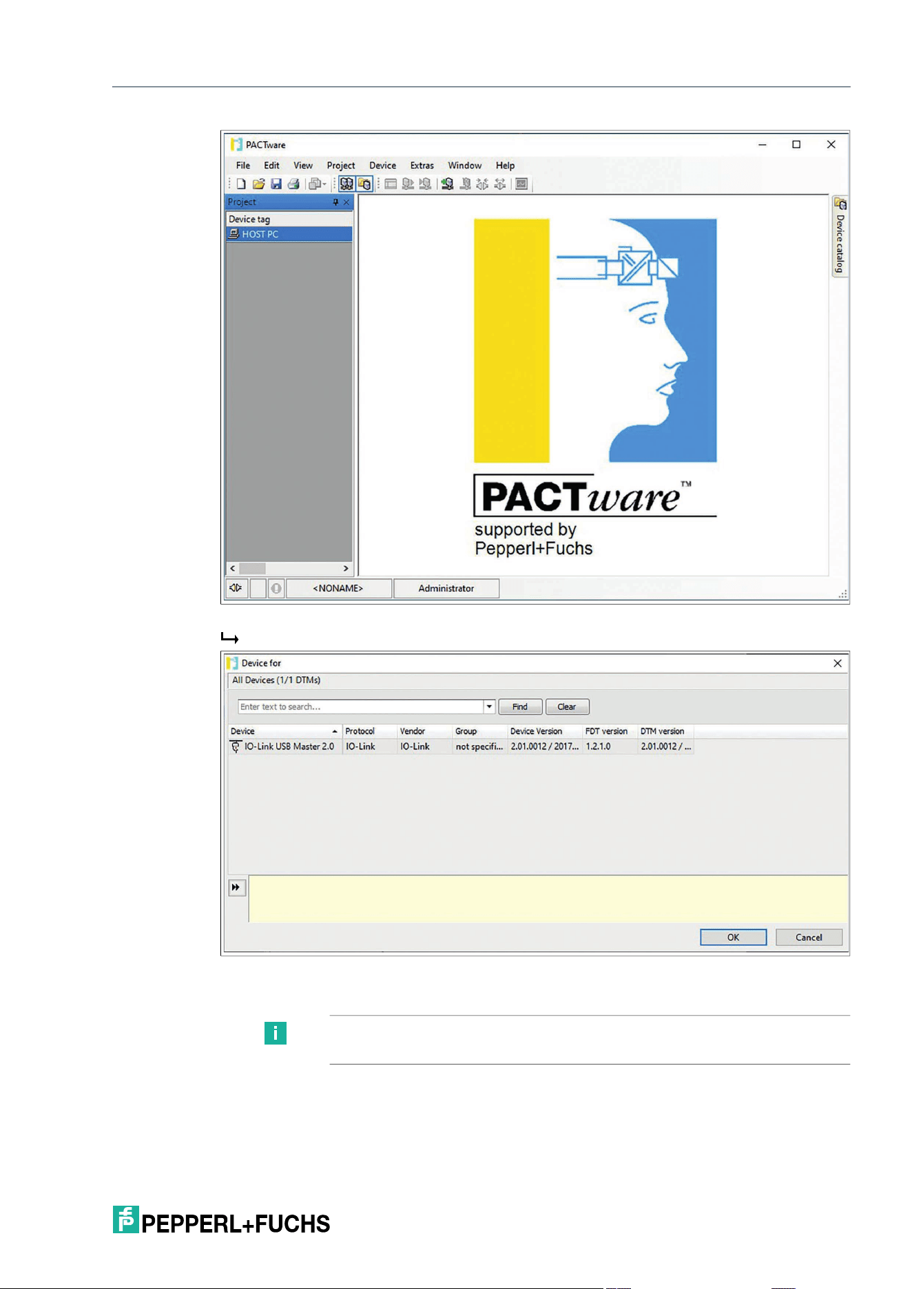
IQT3 / IQT4 Series
Easy Mode
2026-05
45
Figure 7.7
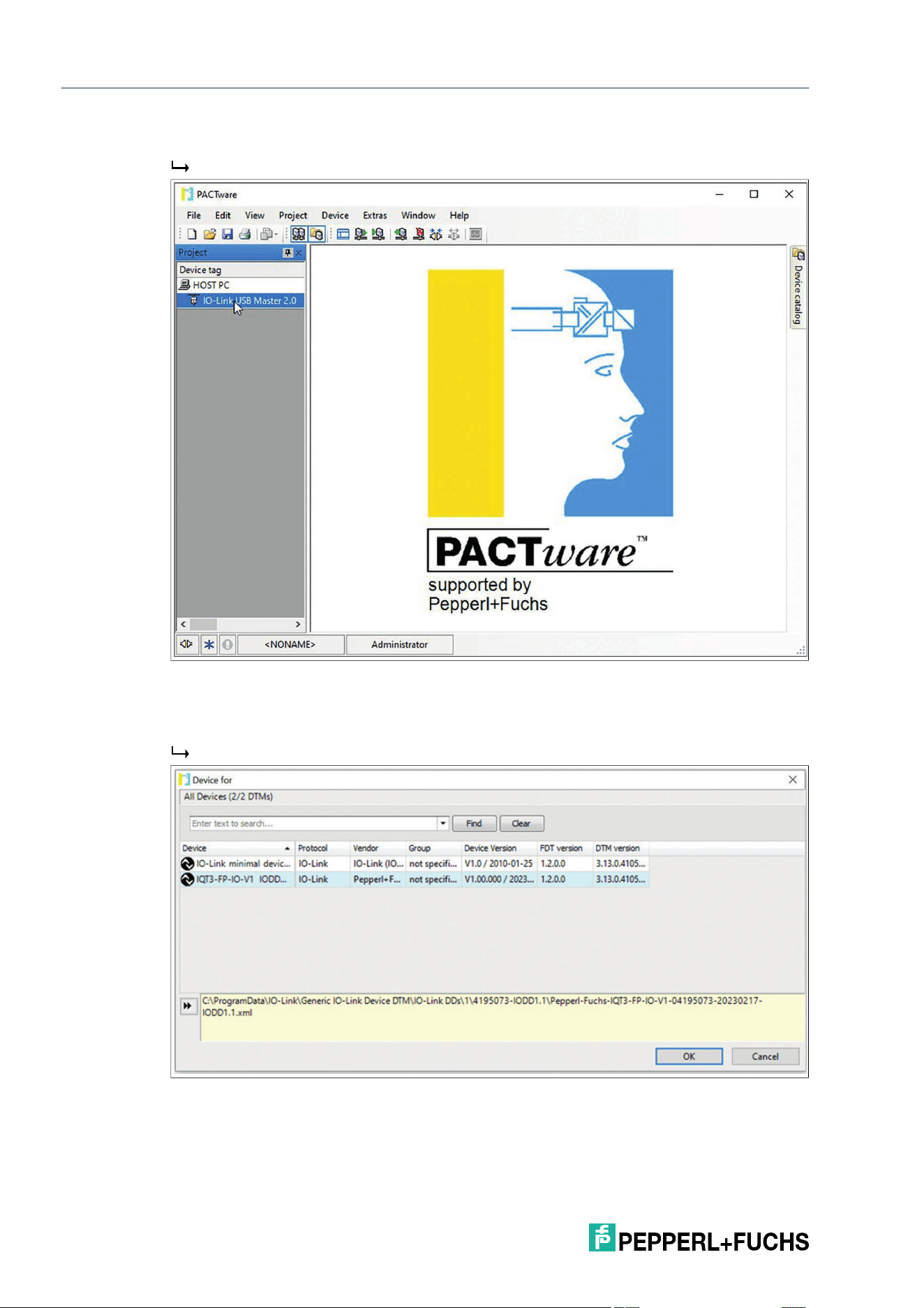
The "Device for" window opens.
Figure 7.8
14. Select IO-Link USB Master 2.0.
Note
If you are using a different IO-Link master, select it.
2026-05
46
IQT3 / IQT4 Series
Easy Mode
15. Confirm with "OK."
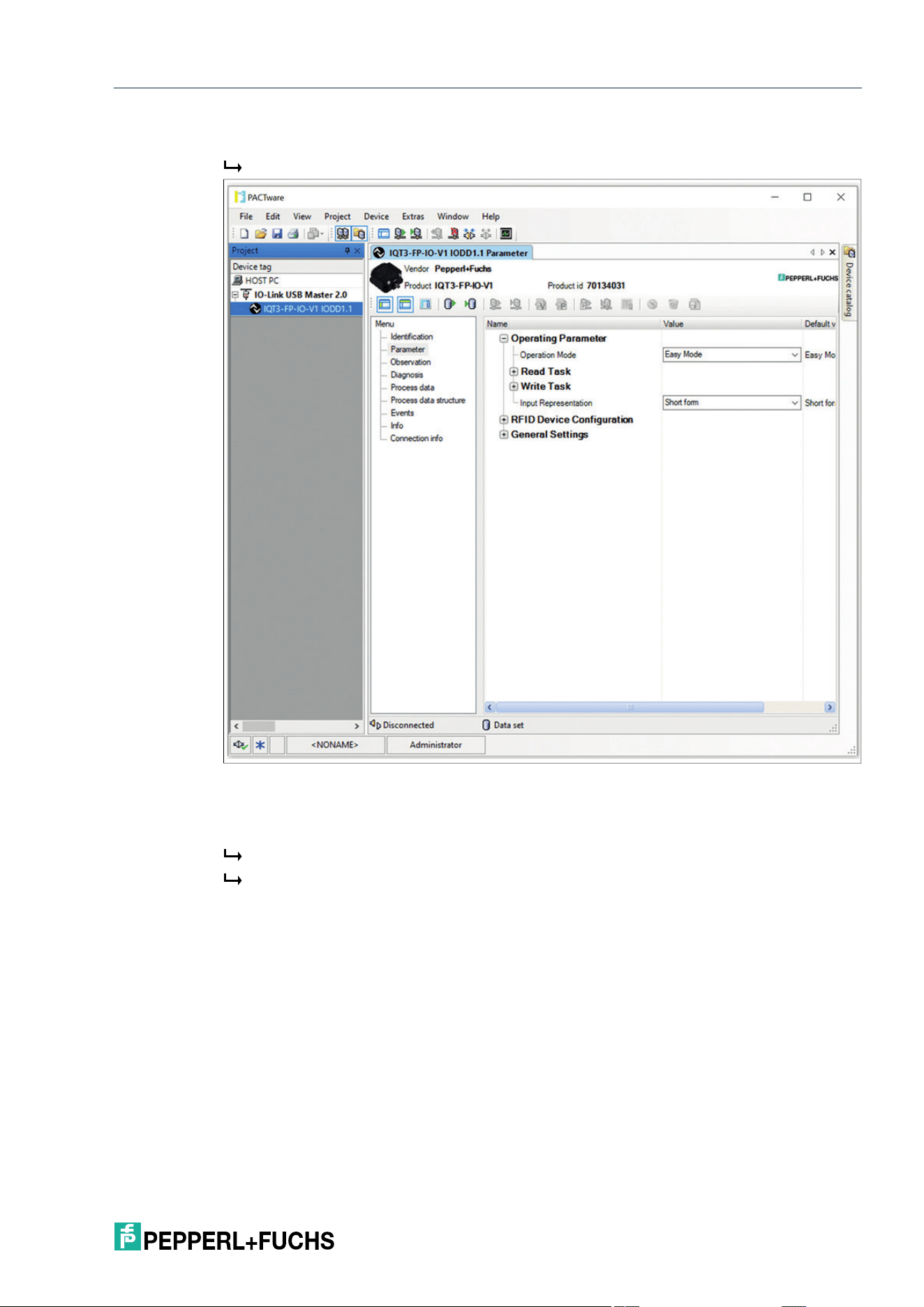
The IO-Link master appears in the menu on the left under your project.
Figure 7.9
16. Right-click on the IO-Link master.
17. Select the "Add device" menu item.
The "Device for" window opens.
Figure 7.10
18. Select the required RFID read/write device.
19. Confirm with "OK."
IQT3 / IQT4 Series
Easy Mode
2026-05
47
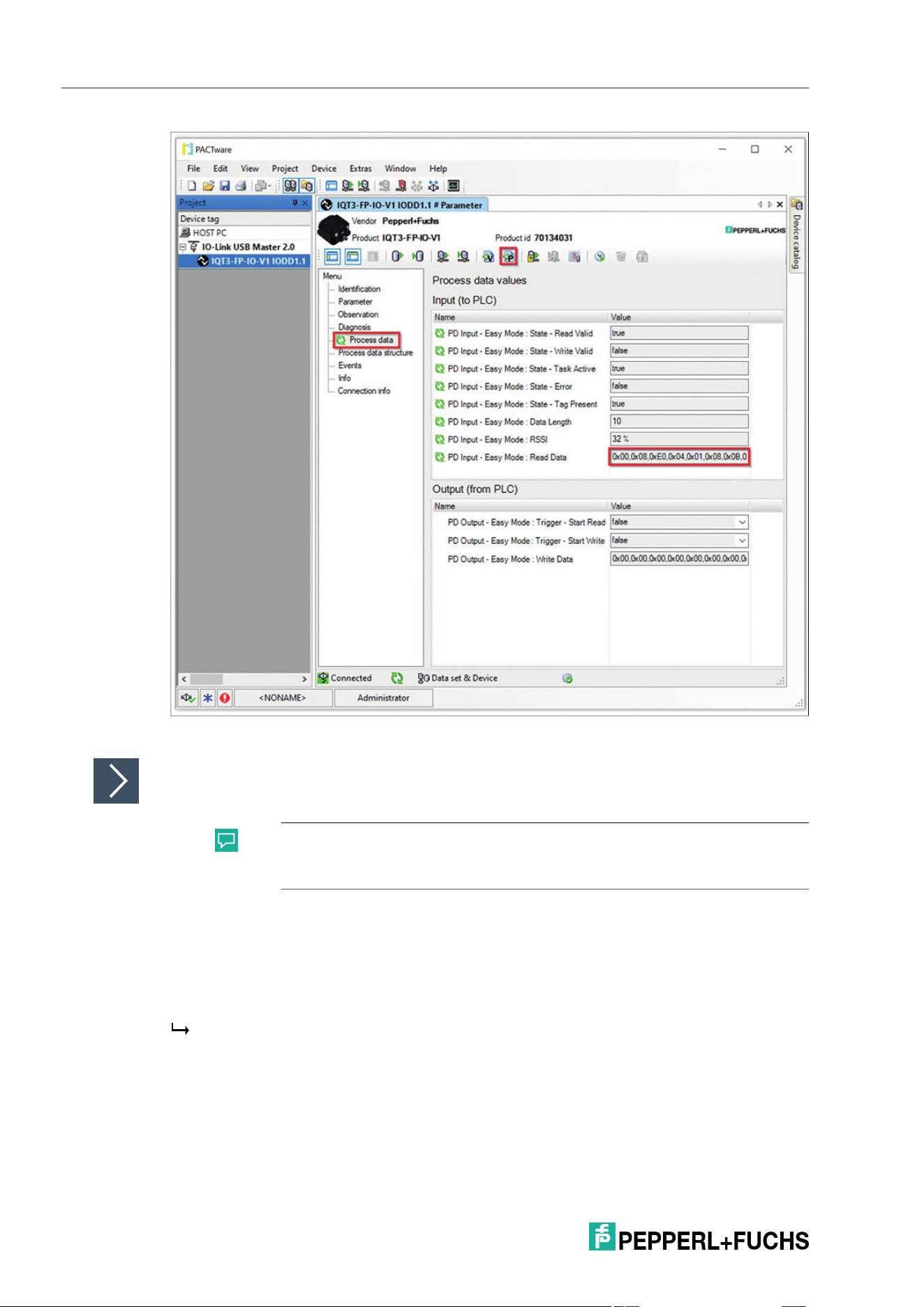
20. Double-click the IO-Link device.
The Parameters menu opens.
Figure 7.11
21. Right-click on the RFID read/write device and select the menu item "Connect."
22. Acknowledge the "Read from Device (Upload)?" dialog with "Yes."
The parameter values displayed in PACTware are transferred to the device.
A connection is established between the IO-Link master and the device.
2026-05
48
IQT3 / IQT4 Series
Easy Mode
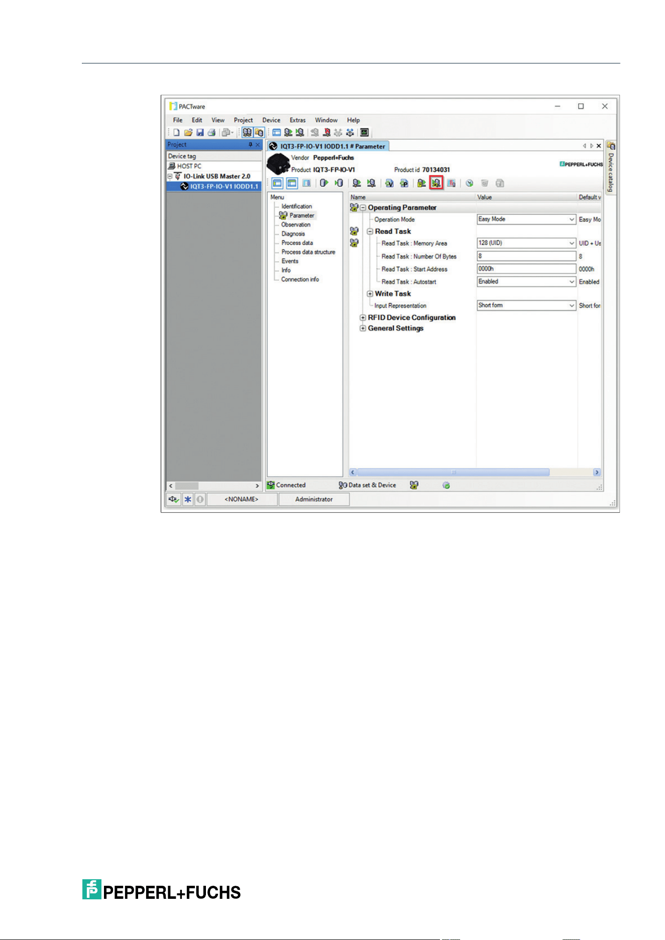
Figure 7.12
As soon as a connection is established, the RFID read/write device automatically starts reading
tags in the sensing range. The data is displayed in the input process data as per the set param-
eters under "Read Task."
1. Adjust the parameters of the device according to your application.
2. In the device selection menu, click on the Parameters entry.
The Parameters menu opens.
3. Change the desired parameters and confirm the entry with the Enter key. Then click the "Write
different values to device" icon.
Tip
Activate the cyclic updating of the process data to display the data in
PACTware.
IQT3 / IQT4 Series
Easy Mode
2026-05
49
Figure 7.13

IQT3 / IQT4 Series
ExpertMode
2026-05
49
8 ExpertMode
8.1 Basic Command Process
As in Easy Mode, the length of the input and output process data is 32 bytes, see chapter 7.
The commands are first combined to form a telegram. This telegram can be significantly longer
than the set in/out length. The telegram is transmitted one after another using individual frag-
ments. The maximum size of a fragment is 32 bytes. A handshake procedure controls the data
transfer.
8.2 Legend
Name Length Meaning
<Number of Tags> 4 bytes The number of tags identified when a single read or
write command is executed. The number of tags is
encoded in ASCII format
<ByteAddress> 2 bytes Start address for read/write access to the user memory
of the tag. The value must be a multiple of 4.
<Command> 1 byte Command code
Identifier of the command to be executed
<ControlByte> 4 bits Control bits for implementing the handshake procedure
or deleting the device memory
<FragmentationCounter> 1 byte Fragmentation counter
Number of fragments still to be transmitted
<FrameLength> 12 bits Number of valid bytes within the telegram
<Length User Data> 2 bytes Length of user data
Specifies the length of the data read in from the user
memory bank
<LengthParameter> 2 bytes Parameter length
Specifies the length of the parameter data set to be
transmitted to the device.
<Number of Bytes> 2 bytes Number of bytes to be accessed during execution of a
read or write command. The value must be a multiple of
4.
<ParameterData> Vari-
able
length
Parameter data
Parameter data set that was read or transmitted.
<ParameterName> 2 bytes Device parameter name
The device parameter name determines the HF param-
eter to be accessed.
<Status> 1 byte Status byte
Status information about the execution state of the com-
mand.
<SystemCode> 1 byte System identifier
The system identifier for the HF system is "Q" (16#51).
<TelegramLength> 2 bytes Length of telegram including all fragments
<UID> 8 bytes Unique Identifier
Unique serial number of a tag
<User Data> Vari-
able
length
Read-in data
Data read in during read access to the user memory
bank
<Write Data> Vari-
able
length
Write data
Data set to be transmitted to the tag.
2026-05
50
IQT3 / IQT4 Series
ExpertMode
8.3 Structure of OUTPUT telegram
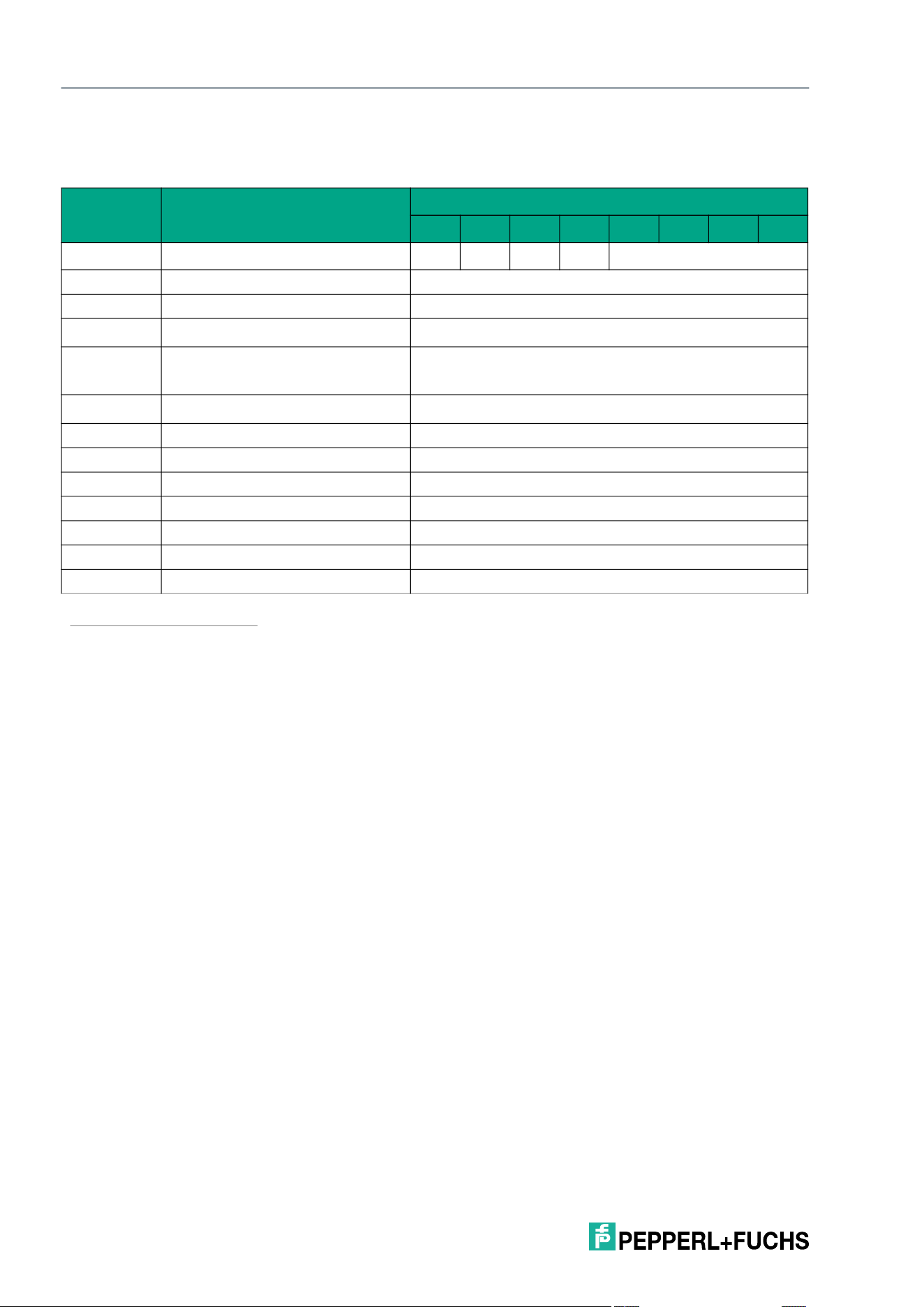
OUTPUT Telegram
The value of <Frame Length> depends on how many <Data Byte> data values must be trans-
mitted to execute a command. It defines the length of the fragment up to and including <Data
Byte X>. If no additional command parameters are required to execute the command, the
length of the fragment extends up to <Command> and has the value 16#06.
The <Fragmentation Counter> has the value 16#00, since the command can be transmitted in
a single fragment by the controller.
The <Telegram Length> specifies the length of the telegram starting from the <Telegram
Length> field itself and including <Data Byte X>. If no additional command parameters are
transmitted, the telegram ends at <Command>, and <Telegram Length> has the value 16#03.
The <Command> byte defines the command to be executed. Different commands are exe-
cuted depending on the value of <Command>. The following classes of commands are avail-
able:
• Read/write commands: Access to one or more tags in the sensing zone
• System commands: Execution of device settings; no access to tags
• HF configuration commands: Setting of the device HF properties
The <Data Byte> fields are used to transmit the data required for execution of a command. This
may include additional command parameters (e.g., start address) or user data to be written to a
tag.
Unused areas within the telegram frame are set to the value 16#00.
Byte Content
Bit number
7 6 5 4 3 2 1 0
0 Control byte / frame length D
S
U
M
U
D
0 <FrameLength>
1 Frame length <Frame Length>
2 Fragmentation counter <Fragmentation Counter>
3
Telegram length (high byte)
1
1.As from the second fragment, parameters/data are transferred from byte 3 onwards.
<Telegram Length (High Byte)>
4
Telegram length (low byte)
1<Default
¬¹ Font>
<Telegram Length (Low Byte)>
5
Command
1<Default ¬¹ Font>
<Command>
6 Parameter/data <Data Byte 1>
7 Parameter/data <Data Byte 2>
8 Parameter/data ...
... Parameter/data <Data Byte X>
... Parameter/data 16#00
... Parameter/data ...
31 Parameter/data 16#00
Table 8.1
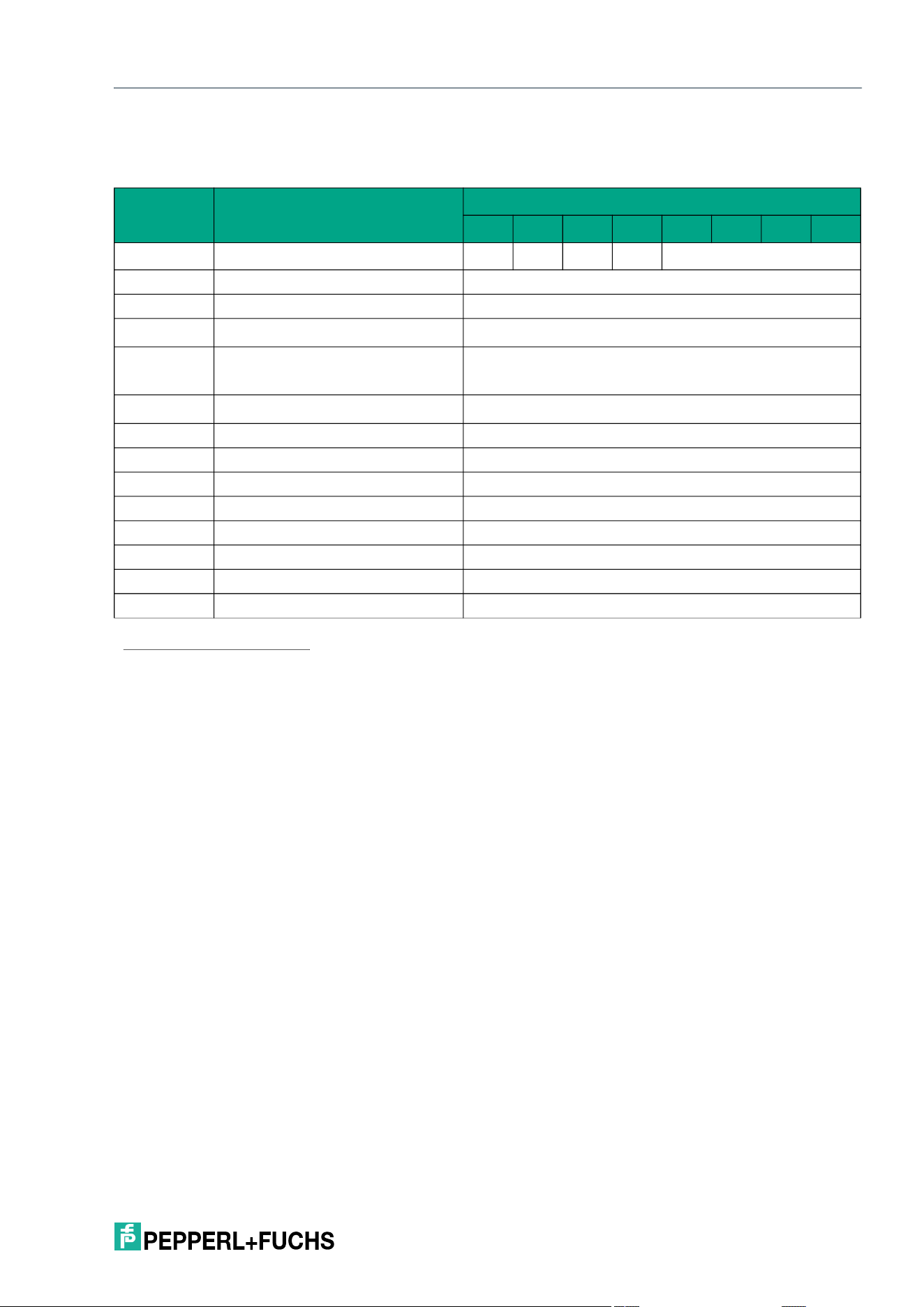
IQT3 / IQT4 Series
ExpertMode
2026-05
51
8.4 Structure of INPUT telegram
INPUT Telegram
The value of <Frame Length> depends on how many <Data Byte> data values are returned by
the device in the command response. It specifies the length of the fragment up to and including
<Data Byte X>. If no additional data values are included in the command response, the frag-
ment length extends up to <Status> and has the value 16#07.
Since the command response can be transmitted in a single fragment by the controller, the
<Fragmentation Counter> has the value 16#00.
The <Telegram Length> specifies the length of the telegram starting from the <Telegram
Length> field itself and including <Data Byte X>. If no additional response parameters are
transmitted, the telegram ends at <Status>, and <Telegram Length> has the value 16#04.
The <Command> byte is a mirror of the command code from the command in the response.
The value of <Status> indicates the command execution status. Error states are indicated by
corresponding status values. .
The <Data Byte> bytes contain the data returned by the device in response to the command.
This could be data read from a tag or parameter values for the HF settings.
Unused areas within the response telegram are set to 16#00.
Byte Content
Bit number
7 6 5 4 3 2 1 0
0 Control Byte / Frame Length D
S
U
M
U
D
0 <FrameLength>
1 Frame length <Frame Length>
2 Fragmentation counter <Fragmentation Counter>
3
Telegram length (high byte)
1
1.As from the second fragment, parameters/data are transferred from byte 3 onwards.
<Telegram Length (High Byte)>
4
Telegram length (low byte)
1<Default
¬¹ Font>
<Telegram Length (Low Byte)>
5
Command
1<Default ¬¹ Font>
<Command>
6 Status <Status>
7 Parameter/data <Data Byte 1>
8 Parameter/data <Data Byte 2>
... Parameter/data ...
... Parameter/data <Data Byte X>
... Parameter/data 0x00
... Parameter/data ...
31 Parameter/data 0x00
Table 8.2
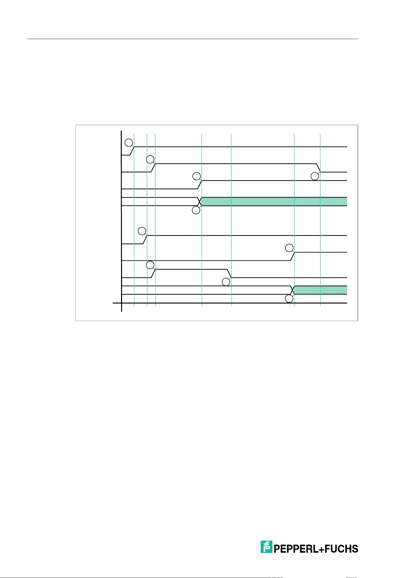
2026-05
52
IQT3 / IQT4 Series
ExpertMode
8.5 Handshake Procedure
Data flow between a PLC and the read/write device must be synchronized to ensure continu-
ous data transfer with no losses. The input and output process data is transmitted in cycles.
Control of the data flow via the software is referred to as "handshaking." The necessary control
bits are contained in the control byte (see chapter 8.4 and see chapter 8.3).
The following handshake procedure is used to transmit telegrams safely and quickly between
the PLC and the device:
D
S
Delete bit; deletes internal memory of the device
U
M
Update master bit
U
D
Update device bit
T1 The PLC changes the delete bit D
S
in the output process data to High (A), which deletes
the FIFO memory in the device.
T2 The read/write station changes the delete bit in the input process data (B) in response
and deletes the entire contents of the FIFO memory
T3 The PLC mirrors the inverted state of U
S
-INPUT from the input field to the output field (C).
Likewise, the device mirrors the inverted state of U
M
-OUTPUT to the input field (D). Both
communication partners are indicating that they are ready to receive a telegram.
T4 The PLC enters an Enhanced Read command (ER) in IF-OUT (Ident Frame) (F). At the
same time, the PLC applies U
M
-INPUT in U
M
-OUTPUT (E) and thus indicates the validity
of a new telegram.
T5 The device mirrors the inverted state of U
M
-OUTPUT to U
M
-INPUT (G). This informs the
control panel that the telegram has been received.
T6 The device has processed the ER and enters the response to the command in the input
field (I). In the same telegram, U
S
-OUTPUT is mirrored in U
S
-INPUT (H).
T7 The PLC has received the changed U
S
-INPUT and mirrors the inverted state in U
S
-OUT-
PUT (J). Only now can the device send another telegram.
T1
T2
T3 T4 T5 T6 T7
D
U
U
IF
OUT
DATA
{
{
IN
DATA
D
U
U
IF
A
B
C
D
E
F
G
J
H
D
M
S
D
M
S
I
Response to ER
Command Enhanced Read (ER)

IQT3 / IQT4 Series
ExpertMode
2026-05
53
Example implementation in the controller
Device Delete Bit D
S
:
Once the device is ready for operation (IO-Link communication = OK), this instruction must be
executed once. This deletes the internal telegram buffer. If an internal device fault has
occurred, the internal telegram buffer should be deleted.
D
S
_OUTPUT := NOT D
S
_INPUT
Device Update Bit U
D
:
New, valid data will be in the input process data if U
D
bits in the input and output process data
have the same value. The device writes new read data to the input process data only once the
PLC has read the input process data, i.e., the U
D
bit in the input and output process data has an
inverted signal state.
To prevent transmission of the read data from being blocked, the inverted state of the U
D
bit
must be transmitted from the input process data to the U
D
bit of the output process data in each
cycle.
U
D
_OUTPUT := NOT U
D
_INPUT (* copy the inverted update bit from the INPUT telegram to
the OUTPUT telegram *)
Master Update Bit U
M
:
The device must be ready to receive new telegrams before a command is sent. This is the case
if the U
M
bit in the input and output process data has an inverted signal state.
The command parameters must then be transmitted to the corresponding positions in the out-
put process data.
The PLC transfers the new command to the device once the U
M
bit in the output process data
is set to the same signal state as the U
M
bit in the input process data.
OUTPUT[1..x] := new telegram
IF (U
M
_OUTPUT <> U
M
_INPUT) then (* check whether the device can receive new data *)
U
M
_OUTPUT := U
M
_INPUT (* device is ready to receive, transfer of update bit *)
End_IF
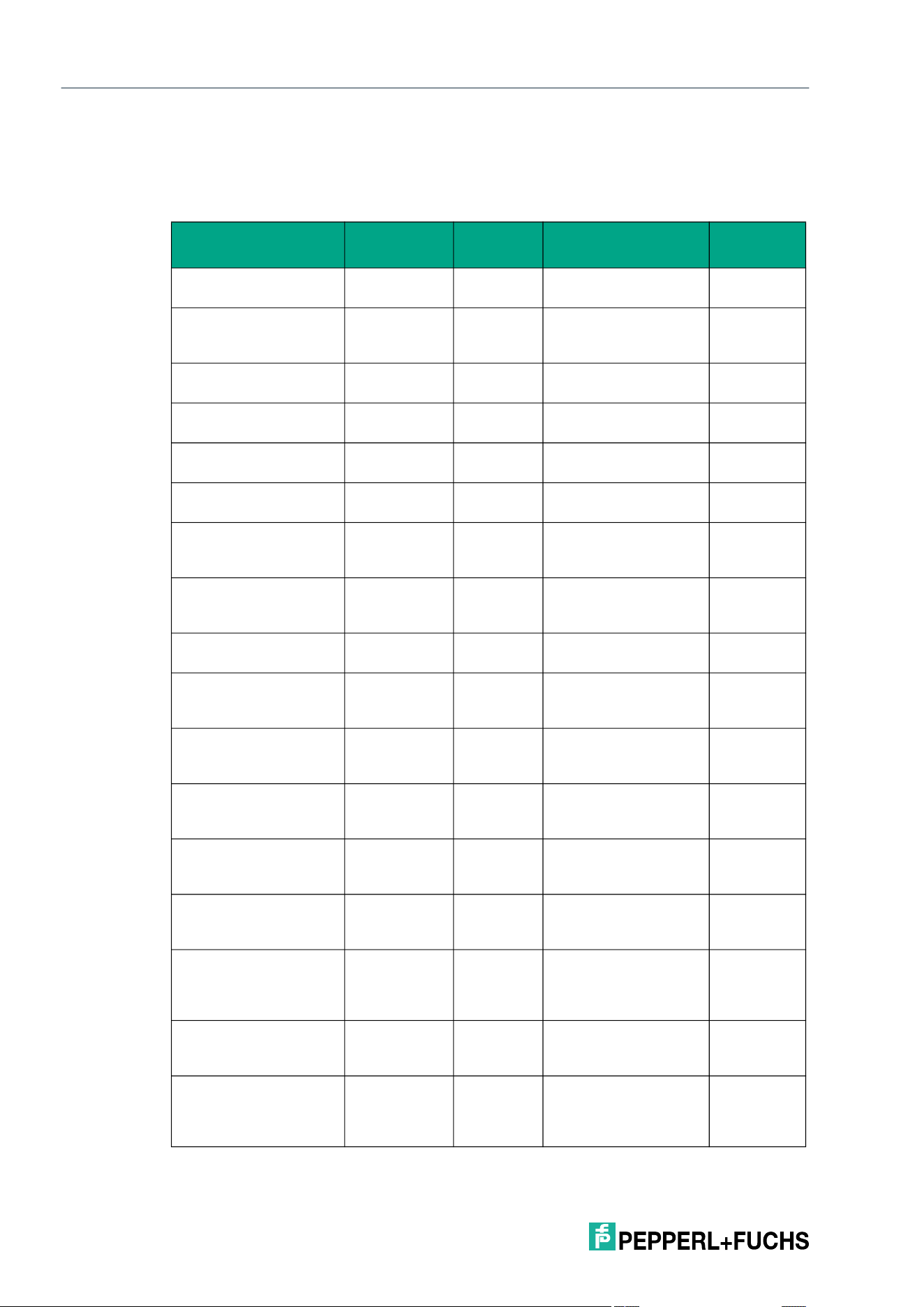
2026-05
54
IQT3 / IQT4 Series
ExpertMode
8.6 Command Overview
The commands in the list are described in detail on the following pages.
Read/Write Commands
Command name
Command
abbreviation
Command
code
Command
description
System
Single Read Fixcode SF 16#01 Single read access to
the fixed code (UID)
IQT3, IQT4
Enhanced Read Fix-
code
EF 16#1D Permanent read
access to the fixed
code (UID)
IQT3, IQT4
Single Read 4 Byte
Blocks
SR 16#10 Single read access to
user memory
IQT3, IQT4
Enhanced Read 4 Byte
Blocks
ER 16#19 Permanent read
access to user memory
IQT3, IQT4
Single Write 4 Byte
Blocks
SW 16#40 Single write access to
user memory
IQT3, IQT4
Enhanced Write 4 Byte
Blocks
EW 16#1A Permanent write
access to user memory
IQT3, IQT4
Single Write 4 Byte
Blocks with Lock
SL 16#47 Single write access to
user memory with write
protection
IQT3, IQT4
Enhanced Write 4 Byte
Blocks with Lock
EL 16#48 Permanent write
access to user mem-
ory with write protection
IQT3, IQT4
Single Read Configura-
tion
SG 16#61 Single read access to
the configuration area
IQT3, IQT4
Enhanced Read Config-
uration
EG 16#68 Permanent read
access to the configu-
ration area
IQT3, IQT4
Single Write Configura-
tion
SC 16#12 Single write access to
AFI/DSFID in the con-
figuration area
IQT3, IQT4
Enhanced Write Config-
uration
EC 16#66 Permanent write
access to AFI/DSFID in
the configuration area
IQT3, IQT4
Fill Tag S# 16#AA Write access to the
user memory with fill
sign
IQT3, IQT4
Selective Single Read
Fixcode
XSF 16#E8 Single read access to
the fixed code (UID) of
a selected tag
IQT3
1
, IQT4
Selective Enhanced
Read Fixcode
XEF 16#E9 Permanent read
access to the fixed
code (UID) of a
selected tag
IQT3
1<Default
¬¹ Font>
, IQT4
Selective Single Read 4
Byte Blocks
XSR 16#E0 Single read access to
the user memory of a
selected tag
IQT3
1<Default
¬¹ Font>
, IQT4
Selective Enhanced
Read 4 Byte Blocks
XER 16#D9 Permanent read
access to the user
memory of a selected
tag
IQT3
1<Default
¬¹ Font>
, IQT4
IQT3 / IQT4 Series
ExpertMode
2026-05
55
System Commands
Configuration Commands
Selective Single Write 4
Byte Blocks
XSW 16#E3 Single write access to
the user memory of a
selected tag
IQT3
1<Default
¬¹ Font>
, IQT4
Selective Enhanced
Write 4 Byte Blocks
XEW 16#DC Permanent write
access to the user
memory of a selected
tag
IQT3
1<Default
¬¹ Font>
, IQT4
Selective Single Write 4
Byte Blocks with Lock
XSL 16#E4 Single write access to
the user memory with
write protection of a
selected tag
IQT3
1<Default
¬¹ Font>
, IQT4
Selective Enhanced
Write 4 Byte Blocks with
Lock
XEL 16#E5 Permanent write
access to the user
memory with write pro-
tection of a selected tag
IQT3
1<Default
¬¹ Font>
, IQT4
Selective Single Read
Configuration
XSG 16#DD Single read access to
AFI/DSFID of a
selected tag
IQT3
1<Default
¬¹ Font>
, IQT4
Selective Enhanced
Read Configuration
XEG 16#D6 Permanent read
access to AFI/DSFID of
a selected tag
IQT3
1<Default
¬¹ Font>
, IQT4
Selective Single Write
Configuration
XSC 16#E1 Single write access to
AFI/DSFID of a
selected tag
IQT3
1<Default
¬¹ Font>
, IQT4
Selective Enhanced
Write Configuration
XEC 16#DA Permanent write
access to AFI/DSFID of
a selected tag
IQT3
1<Default
¬¹ Font>
, IQT4
Selective Fill Tag XS# 16#E7 Write access to the
user memory with fill
sign of a selected tag
IQT3, IQT4
1.from SW Rev. 26
Command
name
Command
abbreviation
Command
code Command description System
Quit QU 16#02 Cancels an active
enhanced command
IQT3, IQT4
Version VE 16#03 Reads out the firmware
version
IQT3, IQT4
Change Tag CT 16#04 Sets the tag type IQT3, IQT4
Command name
Command abbre-
viation
Command
code
Command
description System
Read Parameter RP 16#BE Reads out device
parameters
IQT3, IQT4
Write Parameter WP 16#BF Writes device
parameters
IQT3, IQT4
Command name
Command
abbreviation
Command
code
Command
description System
2026-05
56
IQT3 / IQT4 Series
ExpertMode
8.6.1 Read/Write Commands
The following commands and responses are written using the long-form data format. The end
of a single command is signaled back via a status 16#0F telegram. When using the short-form
data format, the UID and the additional length information are omitted. The end of an enhanced
command is not signaled back.
Single Read Fixcode (SF)
The SF command has the command code 16#01 and performs a single read operation on the
UID of a tag within the sensing zone.
For each tag read, the information read is transmitted in a separate data telegram with the sta-
tus value 16#00. In addition, for each tag read, a further telegram with the status value 16#0B is
transmitted, which contains the RSSI value for the signal strength of the tag response.
The end of the command execution is indicated by an end telegram. The end telegram has the
status value 16#0F and contains the number of tags identified during execution of the com-
mand.
Command telegram
Response telegram 1 – status 16#00 (multiframe protocol)
Byte Content
Bit number
7 6 5 4 3 2 1 0
Byte 0 Control byte / frame
length
D
S
U
M
U
D
0 16#0
Byte 1 Frame length 16#06
Byte 2 Fragmentation counter 16#00
Byte 3 Telegram length (high
byte)
16#00
Byte 4 Telegram length (low
byte)
16#03
Byte 5 Command 16#01
… Command parameter 16#00
Byte 31 Command parameter 16#00
Byte Content
Bit number
7 6 5 4 3 2 1 0
Byte 0 Control byte / frame
length
D
S
U
M
U
D
0 16#0
Byte 1 Frame length 16#11
Byte 2 Fragmentation counter 16#00
Byte 3 Telegram length (high
byte)
16#00
Byte 4 Telegram length (low
byte)
16#0E
Byte 5 Command 16#01
Byte 6 Status 16#00
Byte 7 Data 16#00 <Length UID in Bytes (High Byte)>
Byte 8 Data 16#08 <Length UID in Bytes (Low Byte)>
Byte 9 Data <UID Byte 1>
Byte 10 Data <UID Byte 2>
Byte 11 Data <UID Byte 3>
IQT3 / IQT4 Series
ExpertMode
2026-05
57
Response telegram 2 – status 16#0B (information frame mode
Response telegram 3 – status 16#0F (multiframe protocol)
Byte 12 Data <UID Byte 4>
Byte 13 Data <UID Byte 5>
Byte 14 Data <UID Byte 6>
Byte 15 Data <UID Byte 7>
Byte 16 Data <UID Byte 8>
… Data 16#00
Byte 31 Data 16#00
Byte Content
Bit number
7 6 5 4 3 2 1 0
Byte 0 Control byte / frame
length
D
S
U
M
U
D
0 16#0
Byte 1 Frame length 16#09
Byte 2 Fragmentation counter 16#00
Byte 3 Telegram length (high
byte)
16#00
Byte 4 Telegram length (low
byte)
16#06
Byte 5 Command 16#01
Byte 6 Status 16#0B
Byte 7 Data 16#01 <Info Type>
Byte 8 Data <RSSI>
… Data 16#00
Byte 31 Data 16#00
Byte Content
Bit number
7 6 5 4 3 2 1 0
Byte 0 Control byte / frame
length
D
S
U
M
U
D
0 16#0
Byte 1 Frame length 16#0B
Byte 2 Fragmentation counter 16#00
Byte 3 Telegram length (high
byte)
16#00
Byte 4 Telegram length (low
byte)
16#08
Byte 5 Command 16#01
Byte 6 Status 16#0F
Byte 7 Data <Number of Tags Byte 1>
Byte 8 Data <Number of Tags Byte 2>
Byte 9 Data <Number of Tags Byte 3>
Byte 10 Data <Number of Tags Byte 4>
Byte Content
Bit number
7 6 5 4 3 2 1 0
2026-05
58
IQT3 / IQT4 Series
ExpertMode
Enhanced Buffered Read Fixed code (EF)
The EF command has the command code 16#1D and performs a permanent read operation on
the UID of a tag within the sensing zone.
For each tag read, the information read is transmitted in a separate data telegram with the sta-
tus value 16#00. In addition, for each tag read, a further telegram with the status value 16#0B is
transmitted, which contains the RSSI value for the signal strength of the tag response.
A tag leaving the sensing zone is indicated by a telegram containing the UID of the tag. This
telegram has the status value 16#05.
A Quit command stops the command execution.
Command telegram
Response telegram 1 – status 16#00 (multiframe protocol)
… Data 16#00
Byte 31 Data 16#00
Byte Content
Bit number
7 6 5 4 3 2 1 0
Byte 0 Control byte / frame
length
D
S
U
M
U
D
0 16#0
Byte 1 Frame length 16#06
Byte 2 Fragmentation counter 16#00
Byte 3 Telegram length (high
byte)
16#00
Byte 4 Telegram length (low
byte)
16#03
Byte 5 Command 16#1D
… Command parameter 16#00
Byte 31 Command parameter 16#00
Byte Content
Bit number
7 6 5 4 3 2 1 0
Byte 0 Control byte / frame
length
D
S
U
M
U
D
0 16#0
Byte 1 Frame length 16#11
Byte 2 Fragmentation counter 16#00
Byte 3 Telegram length (high
byte)
16#00
Byte 4 Telegram length (low
byte)
16#0E
Byte 5 Command 16#1D
Byte 6 Status 16#00
Byte 7 Data 16#00 <Length UID in Bytes (High Byte)>
Byte 8 Data 16#08 <Length UID in Bytes (Low Byte)>
Byte 9 Data <UID Byte 1>
Byte 10 Data <UID Byte 2>
Byte Content
Bit number
7 6 5 4 3 2 1 0
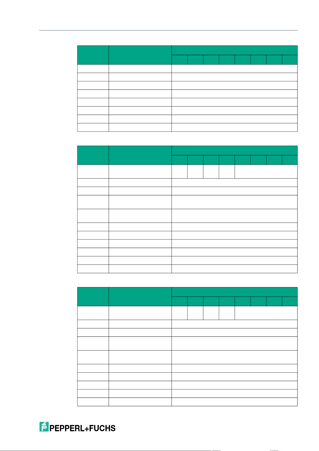
IQT3 / IQT4 Series
ExpertMode
2026-05
59
Response telegram 2 – status 16#0B (information frame mode
Response telegram 3 – status 16#05 (multiframe protocol)
Byte 11 Data <UID Byte 3>
Byte 12 Data <UID Byte 4>
Byte 13 Data <UID Byte 5>
Byte 14 Data <UID Byte 6>
Byte 15 Data <UID Byte 7>
Byte 16 Data <UID Byte 8>
… Data 16#00
Byte 31 Data 16#00
Byte Content
Bit number
7 6 5 4 3 2 1 0
Byte 0 Control byte / frame
length
D
S
U
M
U
D
0 16#0
Byte 1 Frame length 16#09
Byte 2 Fragmentation counter 16#00
Byte 3 Telegram length (high
byte)
16#00
Byte 4 Telegram length (low
byte)
16#06
Byte 5 Command 16#1D
Byte 6 Status 16#0B
Byte 7 Data 16#01 <Info Type>
Byte 8 Data <RSSI>
… Data 16#00
Byte 31 Data 16#00
Byte Content
Bit number
7 6 5 4 3 2 1 0
Byte 0 Control byte / frame
length
D
S
U
M
U
D
0 16#0
Byte 1 Frame length 16#11
Byte 2 Fragmentation counter 16#00
Byte 3 Telegram length (high
byte)
16#00
Byte 4 Telegram length (low
byte)
16#0E
Byte 5 Command 16#1D
Byte 6 Status 16#05
Byte 7 Data 16#00 <Length UID in Bytes (High Byte)>
Byte 8 Data 16#08 <Length UID in Bytes (Low Byte)>
Byte 9 Data <UID Byte 1>
Byte Content
Bit number
7 6 5 4 3 2 1 0
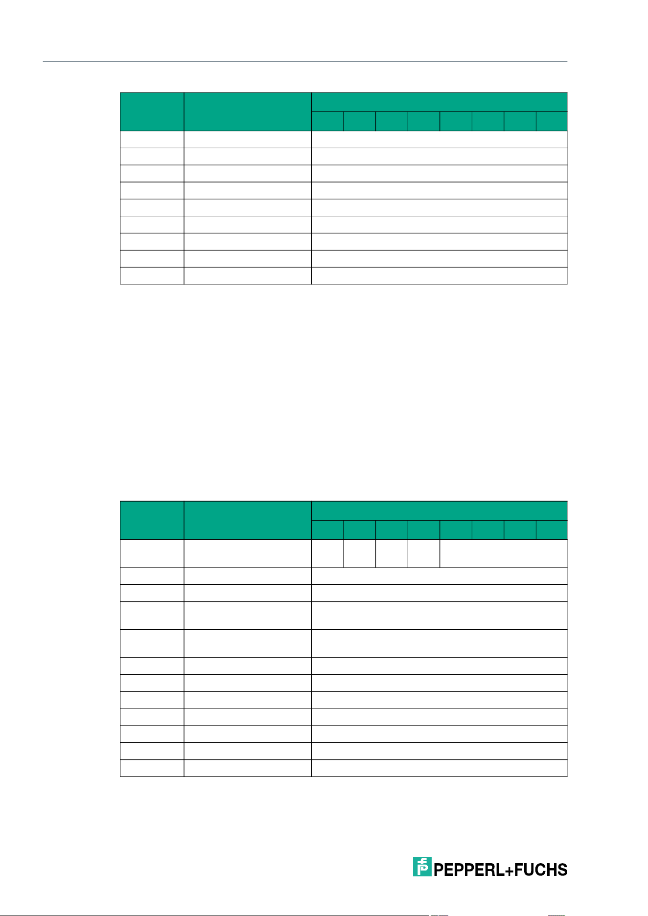
2026-05
60
IQT3 / IQT4 Series
ExpertMode
Single Read 4-Byte Blocks (SR)
The SR command has the command code 16#10 and performs a single read access to the
user data area of a tag within the sensing range.
The <Start Address> parameter specifies the start address within the user data area. The value
of <Start Address> is based on bytes. Only multiples of the memory block size can be parame-
terized. <Number of Bytes> defines the number of bytes to be read. The number of bytes must
be a multiple of the memory block size.
For each tag read, the information read is transmitted in a separate data telegram with the sta-
tus value 16#00. In addition, for each tag read, a further telegram with the status value 16#0B is
transmitted, which contains the RSSI value for the signal strength of the tag response.
The end of the command execution is indicated by an end telegram. The end telegram has the
status value 16#0F and contains the number of tags that were identified during execution of the
command.
Command telegram
Byte 10 Data <UID Byte 2>
Byte 11 Data <UID Byte 3>
Byte 12 Data <UID Byte 4>
Byte 13 Data <UID Byte 5>
Byte 14 Data <UID Byte 6>
Byte 15 Data <UID Byte 7>
Byte 16 Data <UID Byte 8>
… Data 16#00
Byte 31 Data 16#00
Byte Content
Bit number
7 6 5 4 3 2 1 0
Byte 0 Control byte / frame
length
D
S
U
M
U
D
0 16#0
Byte 1 Frame length 16#0A
Byte 2 Fragmentation counter 16#00
Byte 3 Telegram length (high
byte)
16#00
Byte 4 Telegram length (low
byte)
16#07
Byte 5 Command 16#10
Byte 6 Command parameter <Start Address (High Byte)>
Byte 7 Command parameter <Start Address (Low Byte)>
Byte 8 Command parameter <Number of Bytes (High Byte)>
Byte 9 Command parameter <Number of Bytes (Low Byte)>
… Command parameter 16#00
Byte 31 Command parameter 16#00
Byte Content
Bit number
7 6 5 4 3 2 1 0
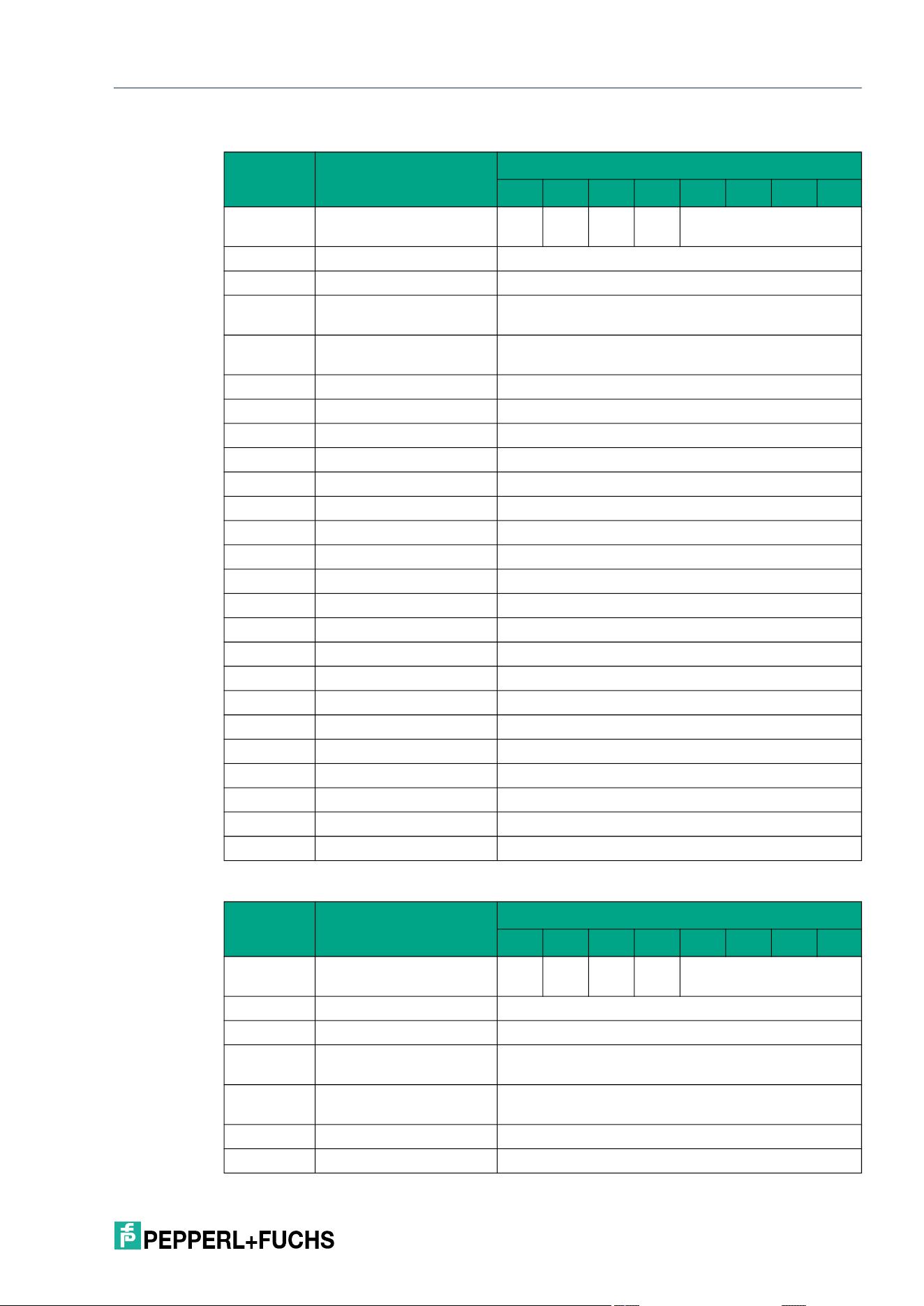
IQT3 / IQT4 Series
ExpertMode
2026-05
61
Response telegram 1 – status 16#00 (multiframe protocol)
Response telegram 2 – status 16#0B (information frame mode
Byte Content
Bit number
7 6 5 4 3 2 1 0
Byte 0 Control byte / frame
length
D
S
U
M
U
D
0 16#0
Byte 1 Frame length 16#17
Byte 2 Fragmentation counter 16#00
Byte 3 Telegram length (high
byte)
16#00
Byte 4 Telegram length (low
byte)
16#14
Byte 5 Command 16#10
Byte 6 Status 16#00
Byte 7 Data 16#00 <Length UID in Bytes (High Byte)>
Byte 8 Data 16#08 <Length UID in Bytes (Low Byte)>
Byte 9 Data <UID Byte 1>
Byte 10 Data <UID Byte 2>
Byte 11 Data <UID Byte 3>
Byte 12 Data <UID Byte 4>
Byte 13 Data <UID Byte 5>
Byte 14 Data <UID Byte 6>
Byte 15 Data <UID Byte 7>
Byte 16 Data <UID Byte 8>
Byte 17 Data 16#00
Byte 18 Data 16#04
Byte 19 Data <User Data Byte 1>
Byte 20 Data <User Data Byte 2>
Byte 21 Data <User Data Byte 3>
Byte 22 Data <User Data Byte 4>
... Data 16#00
Byte 31 Data 16#00
Byte Content
Bit number
7 6 5 4 3 2 1 0
Byte 0 Control byte / frame
length
D
S
U
M
U
D
0 16#0
Byte 1 Frame length 16#09
Byte 2 Fragmentation counter 16#00
Byte 3 Telegram length (high
byte)
16#00
Byte 4 Telegram length (low
byte)
16#06
Byte 5 Command 16#10
Byte 6 Status 16#0B
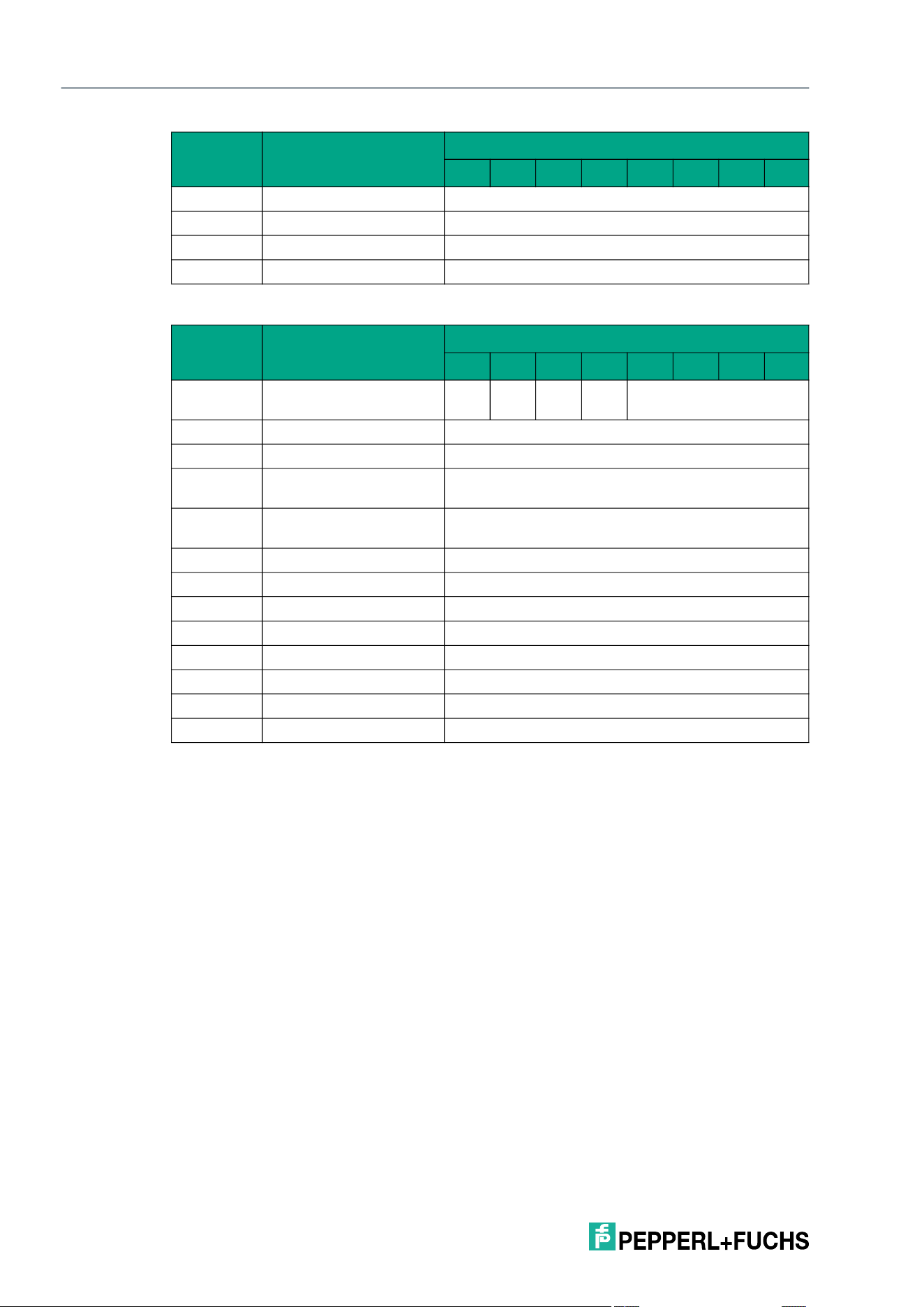
2026-05
62
IQT3 / IQT4 Series
ExpertMode
Response telegram 3 – status 16#0F (multiframe protocol)
Enhanced Read 4-Byte Blocks (ER)
The ER command has the command code 16#19 and performs a permanent read access to
the user data area of a tag within the sensing zone.
The <Start Address> parameter specifies the start address within the user data area. The value
of <Start Address> is based on bytes. Only multiples of the memory block size can be parame-
terized. <Number of Bytes> defines the number of bytes to be read. The number of bytes must
be a multiple of the memory block size.
For each tag read, the information read is transmitted in a separate data telegram with the sta-
tus value 16#00. In addition, for each tag read, a further telegram with the status value 16#0B is
transmitted, which contains information on the signal strength of the tag response (RSSI value).
A tag leaving the sensing zone is indicated by a telegram containing the UID of the tag. This
telegram has the status value 16#05.
A Quit command stops the command execution.
Byte 7 Data 16#01 <Info Type>
Byte 8 Data <RSSI>
… Data 16#00
Byte 31 Data 16#00
Byte Content
Bit number
7 6 5 4 3 2 1 0
Byte 0 Control byte / frame
length
D
S
U
M
U
D
0 16#0
Byte 1 Frame length 16#0B
Byte 2 Fragmentation counter 16#00
Byte 3 Telegram length (high
byte)
16#00
Byte 4 Telegram length (low
byte)
16#08
Byte 5 Command 16#10
Byte 6 Status 16#0F
Byte 7 Data <Number of Tags Byte 1>
Byte 8 Data <Number of Tags Byte 2>
Byte 9 Data <Number of Tags Byte 3>
Byte 10 Data <Number of Tags Byte 4>
… Data 16#00
Byte 31 Data 16#00
Byte Content
Bit number
7 6 5 4 3 2 1 0
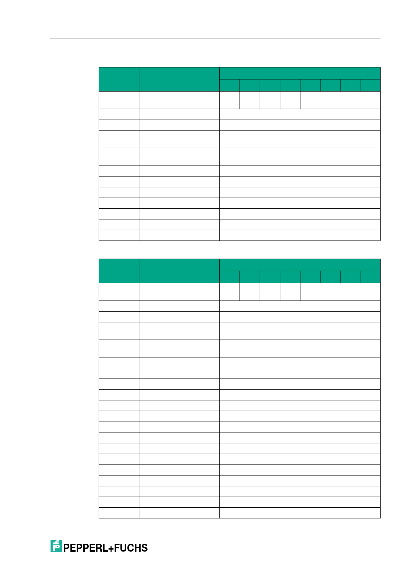
IQT3 / IQT4 Series
ExpertMode
2026-05
63
Command telegram
Response telegram 1 – status 16#00 (multiframe protocol)
Byte Content
Bit number
7 6 5 4 3 2 1 0
Byte 0 Control byte / frame
length
D
S
U
M
U
D
0 16#0
Byte 1 Frame length 16#0A
Byte 2 Fragmentation counter 16#00
Byte 3 Telegram length (high
byte)
16#00
Byte 4 Telegram length (low
byte)
16#07
Byte 5 Command 16#19
Byte 6 Command parameter <Start Address (High Byte)>
Byte 7 Command parameter <Start Address (Low Byte)>
Byte 8 Command parameter <Number of Bytes (High Byte)>
Byte 9 Command parameter <Number of Bytes (Low Byte)>
… Command parameter 16#00
Byte 31 Command parameter 16#00
Byte Content
Bit number
7 6 5 4 3 2 1 0
Byte 0 Control byte / frame
length
D
S
U
M
U
D
0 16#0
Byte 1 Frame length 16#17
Byte 2 Fragmentation counter 16#00
Byte 3 Telegram length (high
byte)
16#00
Byte 4 Telegram length (low
byte)
16#14
Byte 5 Command 16#19
Byte 6 Status 16#00
Byte 7 Data 16#00 <Length UID in Bytes (High Byte)>
Byte 8 Data 16#08 <Length UID in Bytes (Low Byte)>
Byte 9 Data <UID Byte 1>
Byte 10 Data <UID Byte 2>
Byte 11 Data <UID Byte 3>
Byte 12 Data <UID Byte 4>
Byte 13 Data <UID Byte 5>
Byte 14 Data <UID Byte 6>
Byte 15 Data <UID Byte 7>
Byte 16 Data <UID Byte 8>
Byte 17 Data 16#00
Byte 18 Data 16#04
Byte 19 User data <User Data Byte 1>
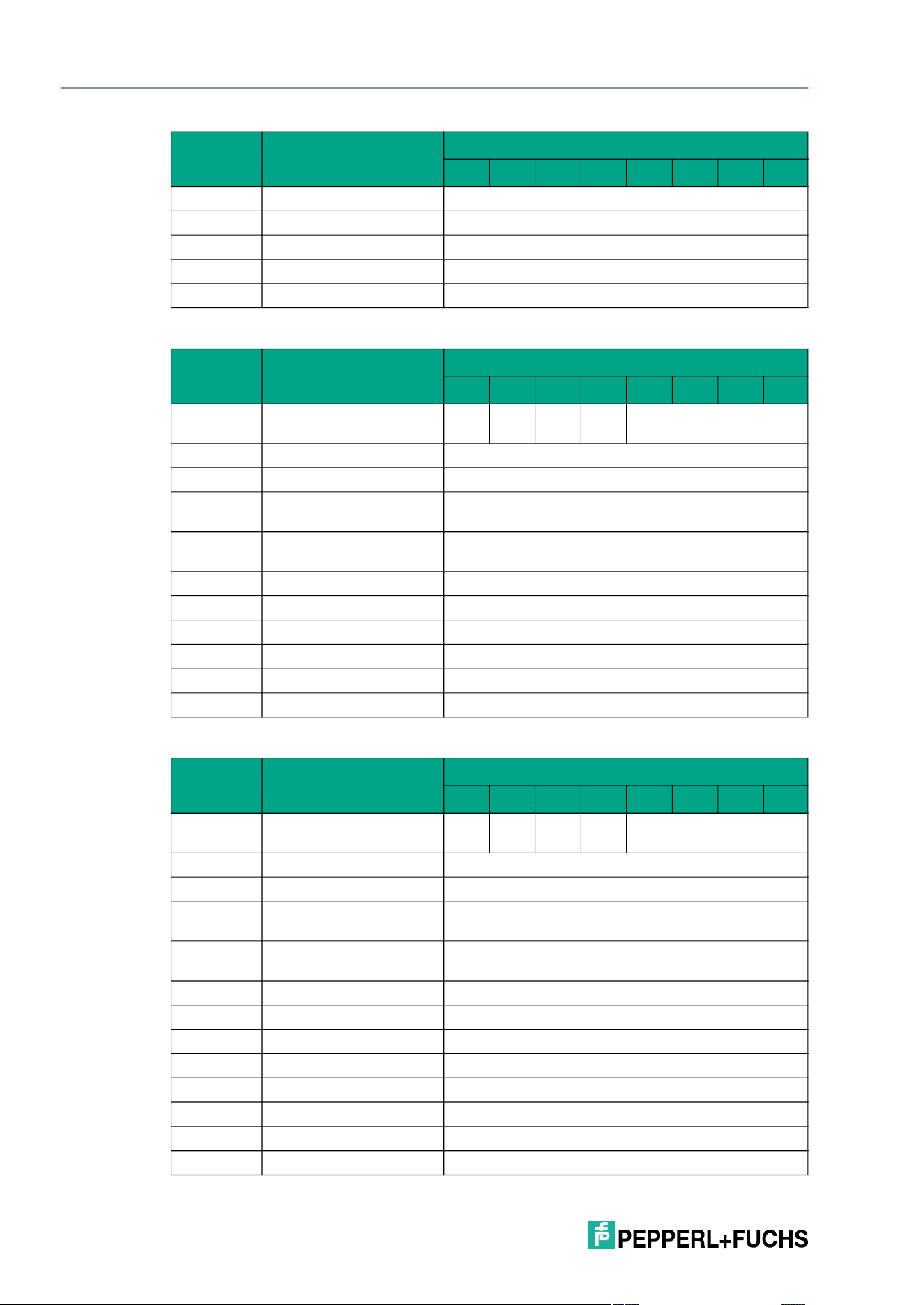
2026-05
64
IQT3 / IQT4 Series
ExpertMode
Response telegram 2 – status 16#0B (information frame mode
Response telegram 3 – status 16#05 (multiframe protocol)
Byte 20 User data <User Data Byte 2>
Byte 21 User data <User Data Byte 3>
Byte 22 User data <User Data Byte 4>
… Data 16#00
Byte 31 Data 16#00
Byte Content
Bit number
7 6 5 4 3 2 1 0
Byte 0 Control byte / frame
length
D
S
U
M
U
D
0 16#0
Byte 1 Frame length 16#09
Byte 2 Fragmentation counter 16#00
Byte 3 Telegram length (high
byte)
16#00
Byte 4 Telegram length (low
byte)
16#06
Byte 5 Command 16#19
Byte 6 Status 16#0B
Byte 7 Data 16#01 <Info Type>
Byte 8 Data <RSSI>
… Data 16#00
Byte 31 Data 16#00
Byte Content
Bit number
7 6 5 4 3 2 1 0
Byte 0 Control byte / frame
length
D
S
U
M
U
D
0 16#0
Byte 1 Frame length 16#11
Byte 2 Fragmentation counter 16#00
Byte 3 Telegram length (high
byte)
16#00
Byte 4 Telegram length (low
byte)
16#0E
Byte 5 Command 16#19
Byte 6 Status 16#05
Byte 7 Data 16#00 <Length UID in Bytes (High Byte)>
Byte 8 Data 16#08 <Length UID in Bytes (Low Byte)>
Byte 9 Data <UID Byte 1>
Byte 10 Data <UID Byte 2>
Byte 11 Data <UID Byte 3>
Byte 12 Data <UID Byte 4>
Byte Content
Bit number
7 6 5 4 3 2 1 0
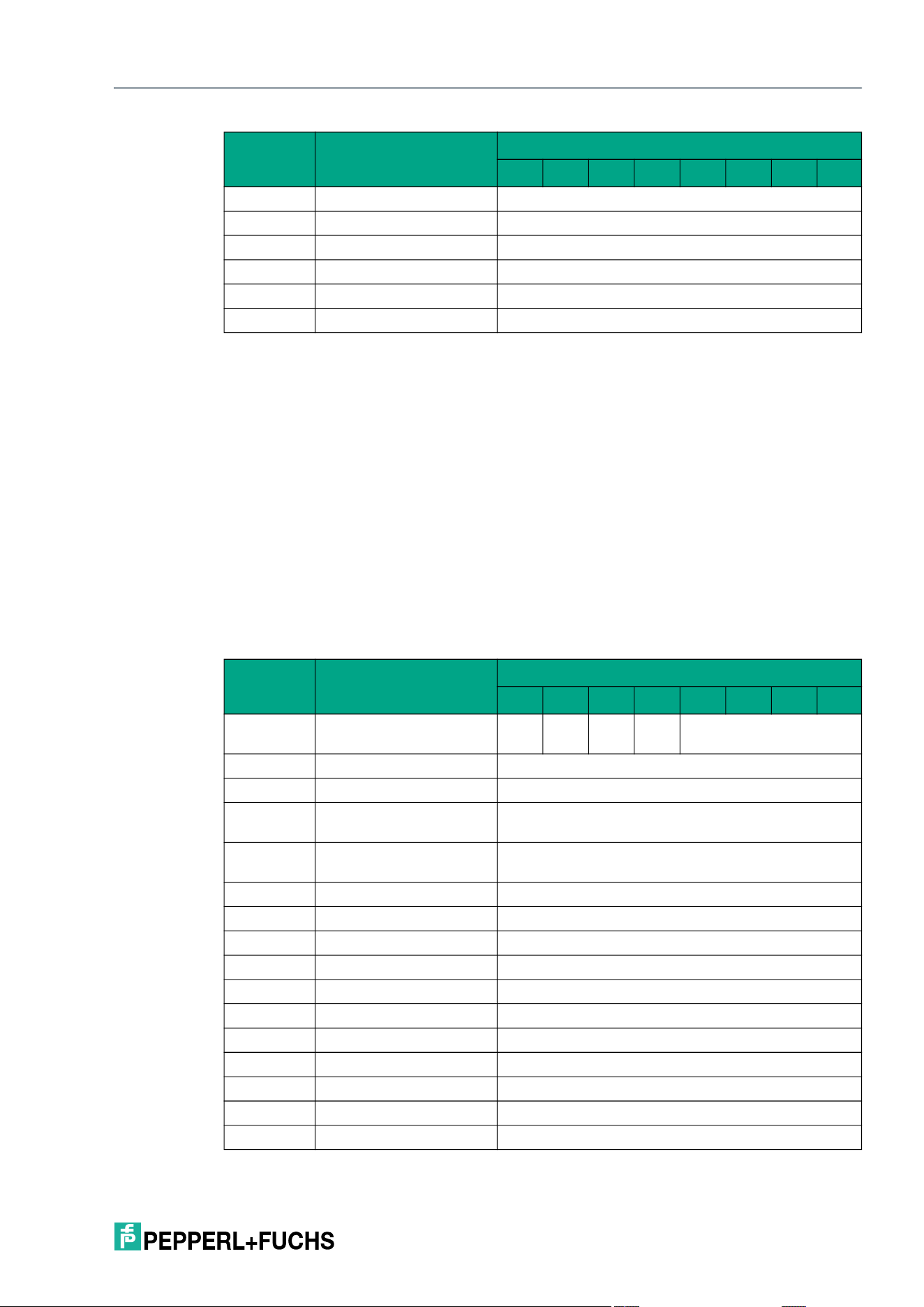
IQT3 / IQT4 Series
ExpertMode
2026-05
65
Single Write 4-Byte Blocks (SW)
The SW command has the command code 16#40 and performs a single write operation to the
user data area of a tag within the sensing range.
The <Start Address> parameter specifies the start address within the user data area. The value
of <Start Address> is based on bytes. Only multiples of the memory block size can be parame-
terized. <Number of Bytes> defines the number of bytes to be written. The number of bytes
must be a multiple of the memory block size.
A separate data telegram with the status value 16#00 indicates a successful write operation for
each tag written. The data telegram contains the UID of the tag to which the user data area was
written. In addition, for each tag written, a further telegram with the status value 16#0B is trans-
mitted, which contains information on the signal strength of the tag response (RSSI value).
The end of the command execution is indicated by an end telegram. The end telegram has the
status value 16#0F and contains the number of tags that were written during execution of the
command.
Command telegram (4 byte user data)
Byte 13 Data <UID Byte 5>
Byte 14 Data <UID Byte 6>
Byte 15 Data <UID Byte 7>
Byte 16 Data <UID Byte 8>
... Data 16#00
Byte 31 Data 16#00
Byte Content
Bit number
7 6 5 4 3 2 1 0
Byte 0 Control byte / frame
length
D
S
U
M
U
D
0 16#0
Byte 1 Frame length 16#0E
Byte 2 Fragmentation counter 16#00
Byte 3 Telegram length (high
byte)
16#00
Byte 4 Telegram length (low
byte)
16#0B
Byte 5 Command 16#40
Byte 6 Command parameter 16#00 <Start Address (High Byte)>
Byte 7 Command parameter 16#00 <Start Address (Low Byte)>
Byte 8 Command parameter 16#00 <Number of Bytes (High Byte)>
Byte 9 Command parameter 16#04 <Number of Bytes (Low Byte)>
Byte 10 Command parameter <Data Byte 1>
Byte 11 Command parameter <Data Byte 2>
Byte 12 Command parameter <Data Byte 3>
Byte 13 Command parameter <Data Byte 4>
… Command parameter 16#00
Byte 31 Command parameter 16#00
Byte Content
Bit number
7 6 5 4 3 2 1 0
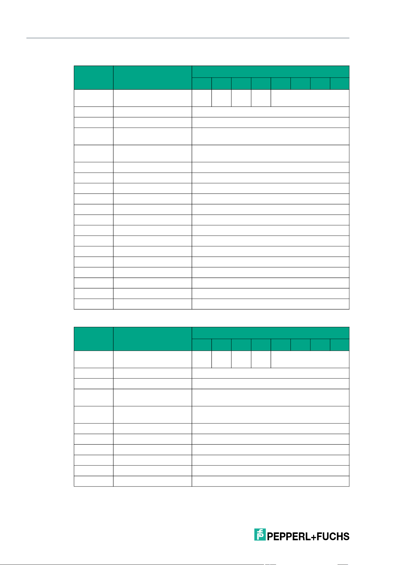
2026-05
66
IQT3 / IQT4 Series
ExpertMode
Response telegram 1 – status 16#00 (multiframe protocol)
Response telegram 2 – status 16#0B (information frame mode
Byte Content
Bit number
7 6 5 4 3 2 1 0
Byte 0 Control byte / frame
length
D
S
U
M
U
D
0 16#0
Byte 1 Frame length 16#11
Byte 2 Fragmentation counter 16#00
Byte 3 Telegram length (high
byte)
16#00
Byte 4 Telegram length (low
byte)
16#0E
Byte 5 Command 16#40
Byte 6 Status 16#00
Byte 7 Data 16#00 <Length UID in Bytes (High Byte)>
Byte 8 Data 16#08 <Length UID in Bytes (Low Byte)>
Byte 9 Data <UID Byte 1>
Byte 10 Data <UID Byte 2>
Byte 11 Data <UID Byte 3>
Byte 12 Data <UID Byte 4>
Byte 13 Data <UID Byte 5>
Byte 14 Data <UID Byte 6>
Byte 15 Data <UID Byte 7>
Byte 16 Data <UID Byte 8>
… Data 16#00
Byte 31 Data 16#00
Byte Content
Bit number
7 6 5 4 3 2 1 0
Byte 0 Control byte / frame
length
D
S
U
M
U
D
0 16#0
Byte 1 Frame length 16#09
Byte 2 Fragmentation counter 16#00
Byte 3 Telegram length (high
byte)
16#00
Byte 4 Telegram length (low
byte)
16#06
Byte 5 Command 16#40
Byte 6 Status 16#0B
Byte 7 Data 16#01 <Info Type>
Byte 8 Data <RSSI>
… Data 16#00
Byte 31 Data 16#00
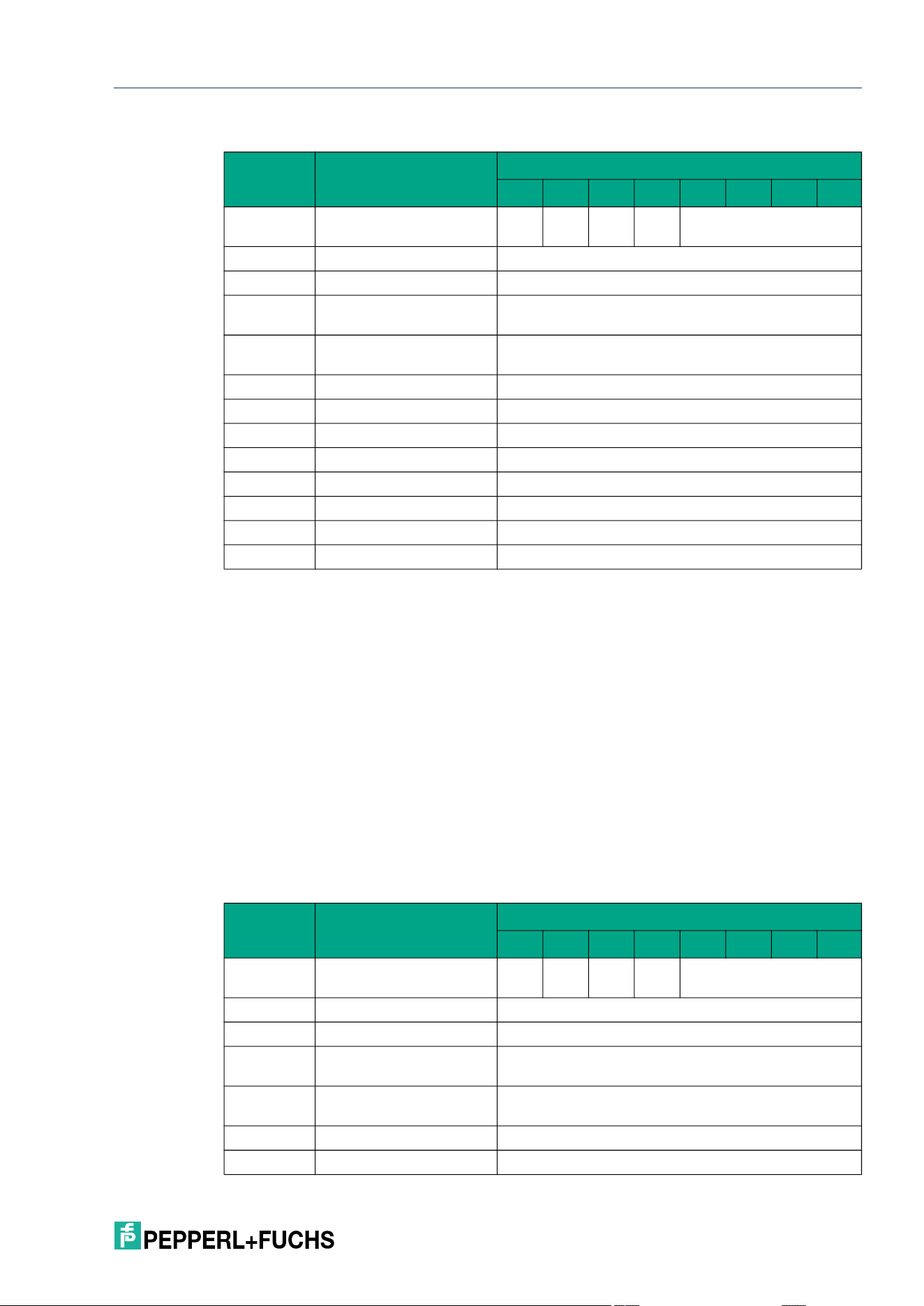
IQT3 / IQT4 Series
ExpertMode
2026-05
67
Response telegram 3 – status 16#0F (multiframe protocol)
Enhanced Write 4-Byte Blocks (EW)
The EW command has the command code 16#1A and performs a permanent write operation
to the user data area of a tag within the sensing range.
The <Start Address> parameter specifies the start address within the user data area. The value
of <Start Address> is based on bytes. Only multiples of the memory block size can be parame-
terized. <Number of Bytes> defines the number of bytes to be written. The number of bytes
must be a multiple of the memory block size.
A separate data telegram with the status value 16#00 indicates a successful write operation for
each tag written. The data telegram contains the UID of the tag to which the user data area was
written. In addition, for each tag written, a further telegram with the status value 16#0B is trans-
mitted, which contains information on the signal strength of the tag response (RSSI value).
A tag leaving the sensing zone is indicated by a telegram containing the UID of the tag. This
telegram has the status value 16#05.
A Quit command stops the command execution.
Command telegram (4 byte user data):
Byte Content
Bit number
7 6 5 4 3 2 1 0
Byte 0 Control byte / frame
length
D
S
U
M
U
D
0 16#0
Byte 1 Frame length 16#0B
Byte 2 Fragmentation counter 16#00
Byte 3 Telegram length (high
byte)
16#00
Byte 4 Telegram length (low
byte)
16#08
Byte 5 Command 16#40
Byte 6 Status 16#0F
Byte 7 Data <Number of Tags Byte 1>
Byte 8 Data <Number of Tags Byte 2>
Byte 9 Data <Number of Tags Byte 3>
Byte 10 Data <Number of Tags Byte 4>
… Data 16#00
Byte 31 Data 16#00
Byte Content
Bit number
7 6 5 4 3 2 1 0
Byte 0 Control byte / frame
length
D
S
U
M
U
D
0 16#0
Byte 1 Frame length 16#0E
Byte 2 Fragmentation counter 16#00
Byte 3 Telegram length (high
byte)
16#00
Byte 4 Telegram length (low
byte)
16#0B
Byte 5 Command 16#1A
Byte 6 Command parameter 16#00 <Start Address (High Byte)>
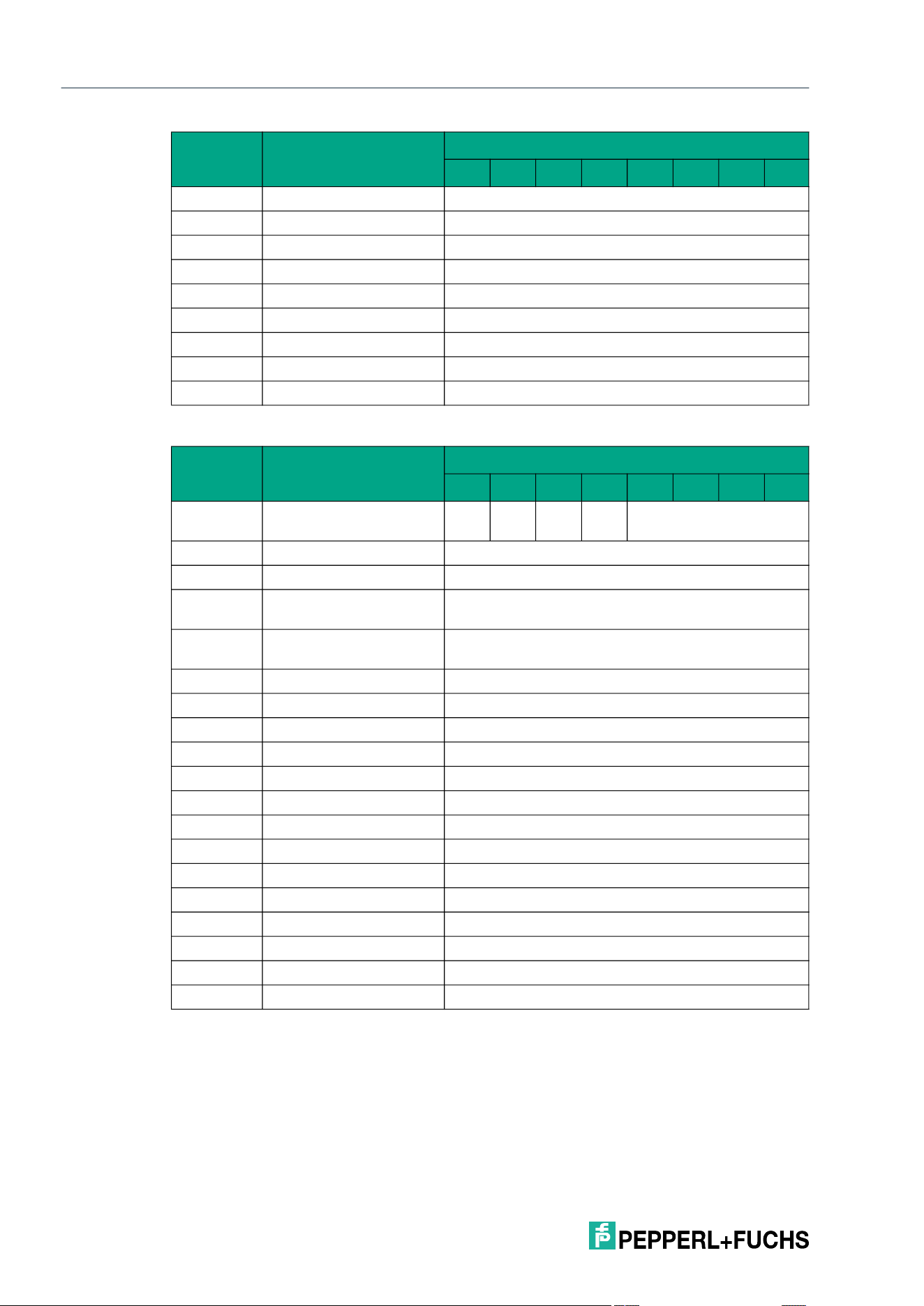
2026-05
68
IQT3 / IQT4 Series
ExpertMode
Response telegram 1 – status 16#00 (multiframe protocol)
Byte 7 Command parameter 16#00 <Start Address (Low Byte)>
Byte 8 Command parameter 16#00 <Number of Bytes (High Byte)>
Byte 9 Command parameter 16#04 <Number of Bytes (Low Byte)>
Byte 10 Command parameter <Data Byte 1>
Byte 11 Command parameter <Data Byte 2>
Byte 12 Command parameter <Data Byte 3>
Byte 13 Command parameter <Data Byte 4>
… Command parameter 16#00
Byte 31 Command parameter 16#00
Byte Content
Bit number
7 6 5 4 3 2 1 0
Byte 0 Control byte / frame
length
D
S
U
M
U
D
0 16#0
Byte 1 Frame length 16#11
Byte 2 Fragmentation counter 16#00
Byte 3 Telegram length (high
byte)
16#00
Byte 4 Telegram length (low
byte)
16#0E
Byte 5 Command 16#1A
Byte 6 Status 16#00
Byte 7 Data 16#00 <Length UID in Bytes (High Byte)>
Byte 8 Data 16#08 <Length UID in Bytes (Low Byte)>
Byte 9 Data <UID Byte 1>
Byte 10 Data <UID Byte 2>
Byte 11 Data <UID Byte 3>
Byte 12 Data <UID Byte 4>
Byte 13 Data <UID Byte 5>
Byte 14 Data <UID Byte 6>
Byte 15 Data <UID Byte 7>
Byte 16 Data <UID Byte 8>
… Data 16#00
Byte 31 Data 16#00
Byte Content
Bit number
7 6 5 4 3 2 1 0
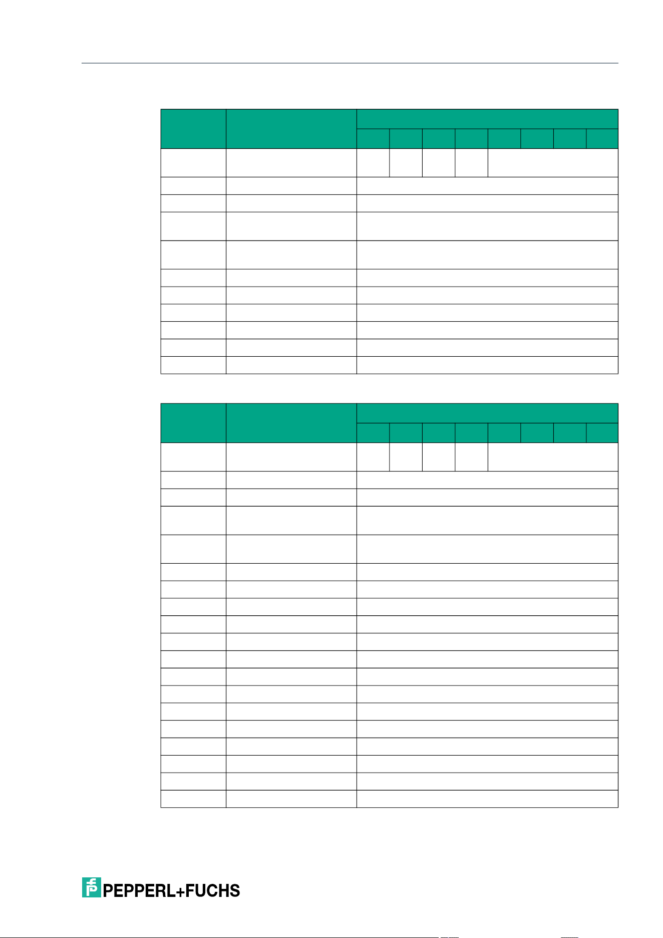
IQT3 / IQT4 Series
ExpertMode
2026-05
69
Response telegram 2 – status 16#0B (information frame mode
Response telegram 3 – status 16#05 (multiframe protocol)
Byte Content
Bit number
7 6 5 4 3 2 1 0
Byte 0 Control byte / frame
length
D
S
U
M
U
D
0 16#0
Byte 1 Frame length 16#09
Byte 2 Fragmentation counter 16#00
Byte 3 Telegram length (high
byte)
16#00
Byte 4 Telegram length (low
byte)
16#06
Byte 5 Command 16#1A
Byte 6 Status 16#0B
Byte 7 Data 16#01 <Info Type>
Byte 8 Data <RSSI>
… Data 16#00
Byte 31 Data 16#00
Byte Content
Bit number
7 6 5 4 3 2 1 0
Byte 0 Control byte / frame
length
D
S
U
M
U
D
0 16#0
Byte 1 Frame length 16#11
Byte 2 Fragmentation counter 16#00
Byte 3 Telegram length (high
byte)
16#00
Byte 4 Telegram length (low
byte)
16#0E
Byte 5 Command 16#1A
Byte 6 Status 16#05
Byte 7 Data 16#00 <Length UID in Bytes (High Byte)>
Byte 8 Data 16#08 <Length UID in Bytes (Low Byte)>
Byte 9 Data <UID Byte 1>
Byte 10 Data <UID Byte 2>
Byte 11 Data <UID Byte 3>
Byte 12 Data <UID Byte 4>
Byte 13 Data <UID Byte 5>
Byte 14 Data <UID Byte 6>
Byte 15 Data <UID Byte 7>
Byte 16 Data <UID Byte 8>
… Data 16#00
Byte 31 Data 16#00
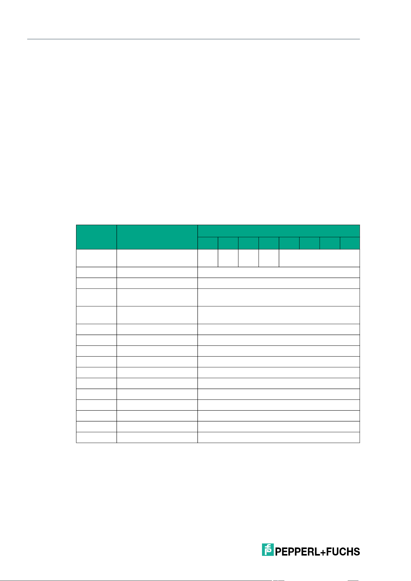
2026-05
70
IQT3 / IQT4 Series
ExpertMode
Single Write 4-Byte Blocks with Lock (SL)
The SL command has the command code 16#47 and performs a single write operation to the
user data area of a tag within the sensing zone. The data is write-protected at the end of the
write process, provided the tag offers this function. This applies to type 21, 22, 24, 33, 50 and
51 tags. The write protection is permanent and cannot be undone. Write protection is only acti-
vated for memory blocks involved in the writing process. Data can continue to be written to all
other memory blocks.
The <Start Address> parameter specifies the start address within the user data area. The value
of <Start Address> is based on bytes. Only multiples of the memory block size can be parame-
terized. <Number of Bytes> defines the number of bytes to be written. The number of bytes
must also be a multiple of the memory block size.
A separate data telegram with the status value 16#00 indicates a successful write operation for
each tag written. The data telegram contains the UID of the tag to which the user data area was
written. In addition, for each tag written, a further telegram with the status value 16#0B is trans-
mitted, which contains information on the signal strength of the tag response (RSSI value).
The end of the command execution is indicated by an end telegram. The end telegram has the
status value 16#0F and contains the number of tags that were written during execution of the
command.
Command telegram (4 byte user data)
Byte Content
Bit number
7 6 5 4 3 2 1 0
Byte 0 Control byte / frame
length
D
S
U
M
U
D
0 16#0
Byte 1 Frame length 16#0E
Byte 2 Fragmentation counter 16#00
Byte 3 Telegram length (high
byte)
16#00
Byte 4 Telegram length (low
byte)
16#0B
Byte 5 Command 16#47
Byte 6 Command parameter 16#00 <Start Address (High Byte)>
Byte 7 Command parameter 16#00 <Start Address (Low Byte)>
Byte 8 Command parameter 16#00 <Number of Bytes (High Byte)>
Byte 9 Command parameter 16#04 <Number of Bytes (Low Byte)>
Byte 10 Command parameter <Data Byte 1>
Byte 11 Command parameter <Data Byte 2>
Byte 12 Command parameter <Data Byte 3>
Byte 13 Command parameter <Data Byte 4>
… Command parameter 16#00
Byte 31 Command parameter 16#00
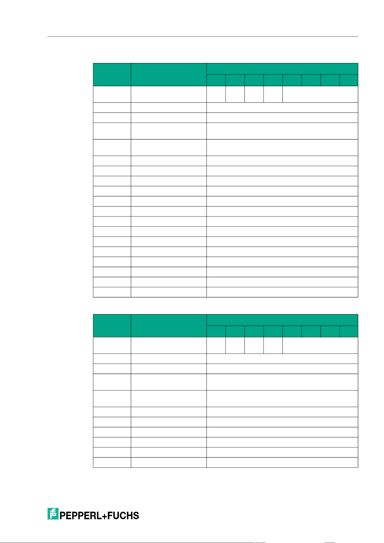
IQT3 / IQT4 Series
ExpertMode
2026-05
71
Response telegram 1 – status 16#00 (multiframe protocol)
Response telegram 2 – status 16#0B (information frame mode
Byte Content
Bit number
7 6 5 4 3 2 1 0
Byte 0 Control byte / frame
length
D
S
U
M
U
D
0 16#0
Byte 1 Frame length 16#11
Byte 2 Fragmentation counter 16#00
Byte 3 Telegram length (high
byte)
16#00
Byte 4 Telegram length (low
byte)
16#0E
Byte 5 Command 16#47
Byte 6 Status 16#00
Byte 7 Data 16#00 <Length UID in Bytes (High Byte)>
Byte 8 Data 16#08 <Length UID in Bytes (Low Byte)>
Byte 9 Data <UID Byte 1>
Byte 10 Data <UID Byte 2>
Byte 11 Data <UID Byte 3>
Byte 12 Data <UID Byte 4>
Byte 13 Data <UID Byte 5>
Byte 14 Data <UID Byte 6>
Byte 15 Data <UID Byte 7>
Byte 16 Data <UID Byte 8>
… Data 16#00
Byte 31 Data 16#00
Byte Content
Bit number
7 6 5 4 3 2 1 0
Byte 0 Control byte / frame
length
D
S
U
M
U
D
0 16#0
Byte 1 Frame length 16#09
Byte 2 Fragmentation counter 16#00
Byte 3 Telegram length (high
byte)
16#00
Byte 4 Telegram length (low
byte)
16#06
Byte 5 Command 16#47
Byte 6 Status 16#0B
Byte 7 Data 16#01 <Info Type>
Byte 8 Data <RSSI>
… Data 16#00
Byte 31 Data 16#00
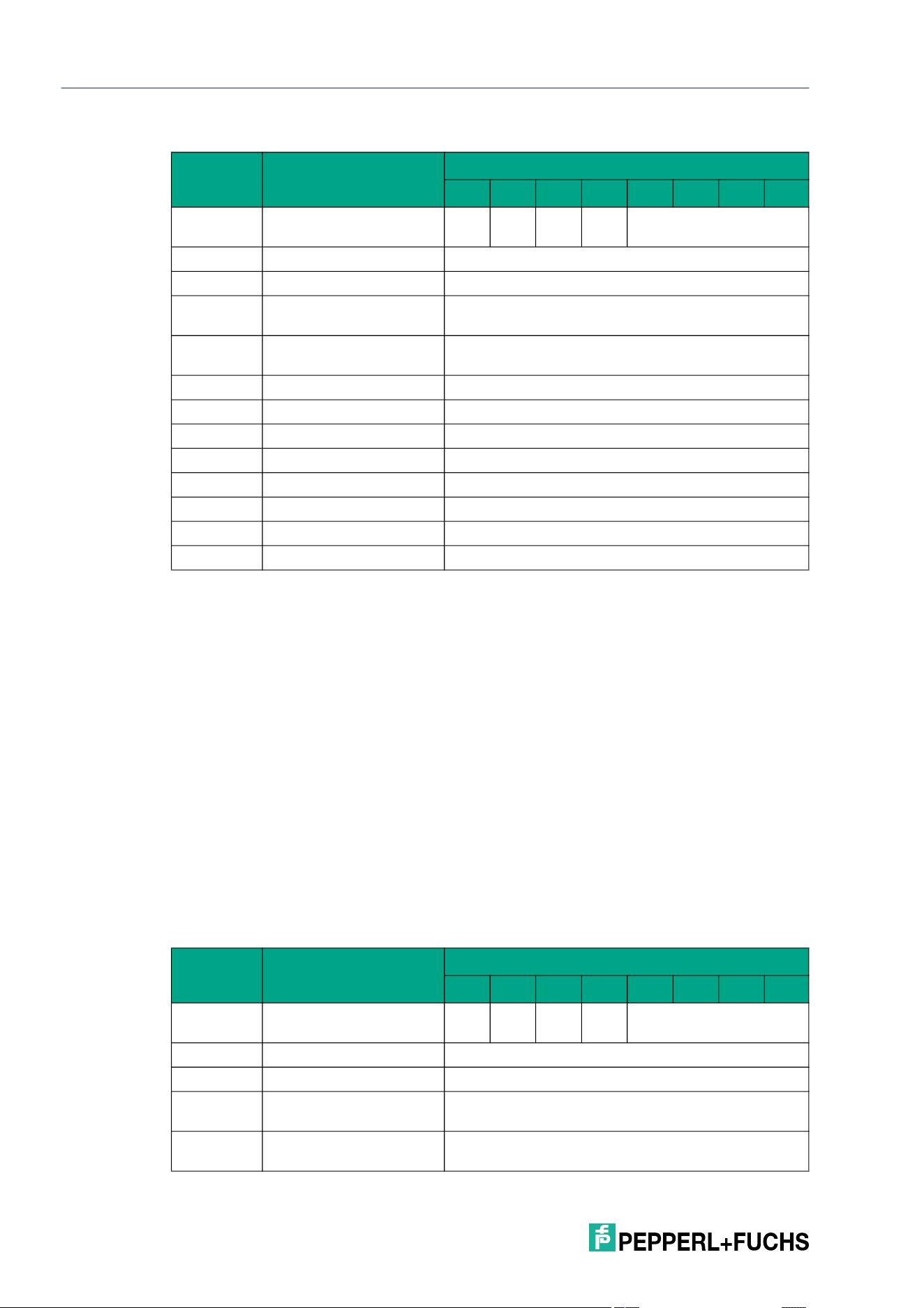
2026-05
72
IQT3 / IQT4 Series
ExpertMode
Response telegram 3 – status 16#0F (multiframe protocol)
Enhanced Write 4-Byte Blocks with Lock (EL)
The EL command has the command code 16#48 and performs a permanent write operation to
the user data area of a tag within the sensing zone. The data is write-protected at the end of the
write process, provided the tag offers this function. This applies to type 21, 22, 24, 33, 50 and
51 tags. The write protection is permanent and cannot be undone. Write protection is only acti-
vated for memory blocks involved in the writing process. Data can continue to be written to all
other memory blocks.
The <Start Address> parameter specifies the start address within the user data area. The value
of <Start Address> is based on bytes. Only multiples of the memory block size can be parame-
terized. <Number of Bytes> defines the number of bytes to be written. The number of bytes
must also be a multiple of the memory block size.
A separate data telegram with the status value 16#00 indicates a successful write operation for
each tag written. The data telegram contains the UID of the tag to which the user data area was
written. In addition, for each tag written, a further telegram with the status value 16#0B is trans-
mitted, which contains information on the signal strength of the tag response (RSSI value).
A tag leaving the sensing zone is indicated by a telegram containing the fixed code of the tag.
This telegram has the status value 16#05. A Quit command stops the command execution.
Command telegram (4 byte user data)
Byte Content
Bit number
7 6 5 4 3 2 1 0
Byte 0 Control byte / frame
length
D
S
U
M
U
D
0 16#0
Byte 1 Frame length 16#0B
Byte 2 Fragmentation counter 16#00
Byte 3 Telegram length (high
byte)
16#00
Byte 4 Telegram length (low
byte)
16#08
Byte 5 Command 16#47
Byte 6 Status 16#0F
Byte 7 Data <Number of Tags Byte 1>
Byte 8 Data <Number of Tags Byte 2>
Byte 9 Data <Number of Tags Byte 3>
Byte 10 Data <Number of Tags Byte 4>
… Data 16#00
Byte 31 Data 16#00
Byte Content
Bit number
7 6 5 4 3 2 1 0
Byte 0 Control byte / frame
length
D
S
U
M
U
D
0 16#0
Byte 1 Frame length 16#0E
Byte 2 Fragmentation counter 16#00
Byte 3 Telegram length (high
byte)
16#00
Byte 4 Telegram length (low
byte)
16#0B
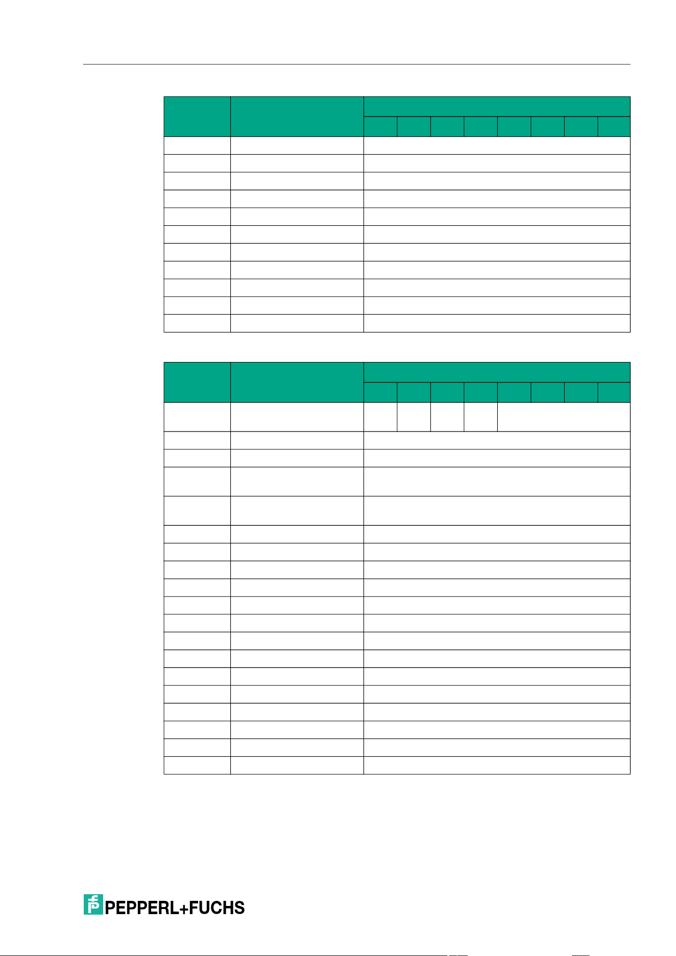
IQT3 / IQT4 Series
ExpertMode
2026-05
73
Response telegram 1 – status 16#00 (multiframe protocol)
Byte 5 Command 16#48
Byte 6 Command parameter 16#00 <Start Address (High Byte)>
Byte 7 Command parameter 16#00 <Start Address (Low Byte)>
Byte 8 Command parameter 16#00 <Number of Bytes (High Byte)>
Byte 9 Command parameter 16#04 <Number of Bytes (Low Byte)>
Byte 10 Command parameter <Data Byte 1>
Byte 11 Command parameter <Data Byte 2>
Byte 12 Command parameter <Data Byte 3>
Byte 13 Command parameter <Data Byte 4>
… Command parameter 16#00
Byte 31 Command parameter 16#00
Byte Content
Bit number
7 6 5 4 3 2 1 0
Byte 0 Control byte / frame
length
D
S
U
M
U
D
0 16#0
Byte 1 Frame length 16#11
Byte 2 Fragmentation counter 16#00
Byte 3 Telegram length (high
byte)
16#00
Byte 4 Telegram length (low
byte)
16#0E
Byte 5 Command 16#48
Byte 6 Status 16#00
Byte 7 Data 16#00 <Length UID in Bytes (High Byte)>
Byte 8 Data 16#08 <Length UID in Bytes (Low Byte)>
Byte 9 Data <UID Byte 1>
Byte 10 Data <UID Byte 2>
Byte 11 Data <UID Byte 3>
Byte 12 Data <UID Byte 4>
Byte 13 Data <UID Byte 5>
Byte 14 Data <UID Byte 6>
Byte 15 Data <UID Byte 7>
Byte 16 Data <UID Byte 8>
… Data 16#00
Byte 31 Data 16#00
Byte Content
Bit number
7 6 5 4 3 2 1 0
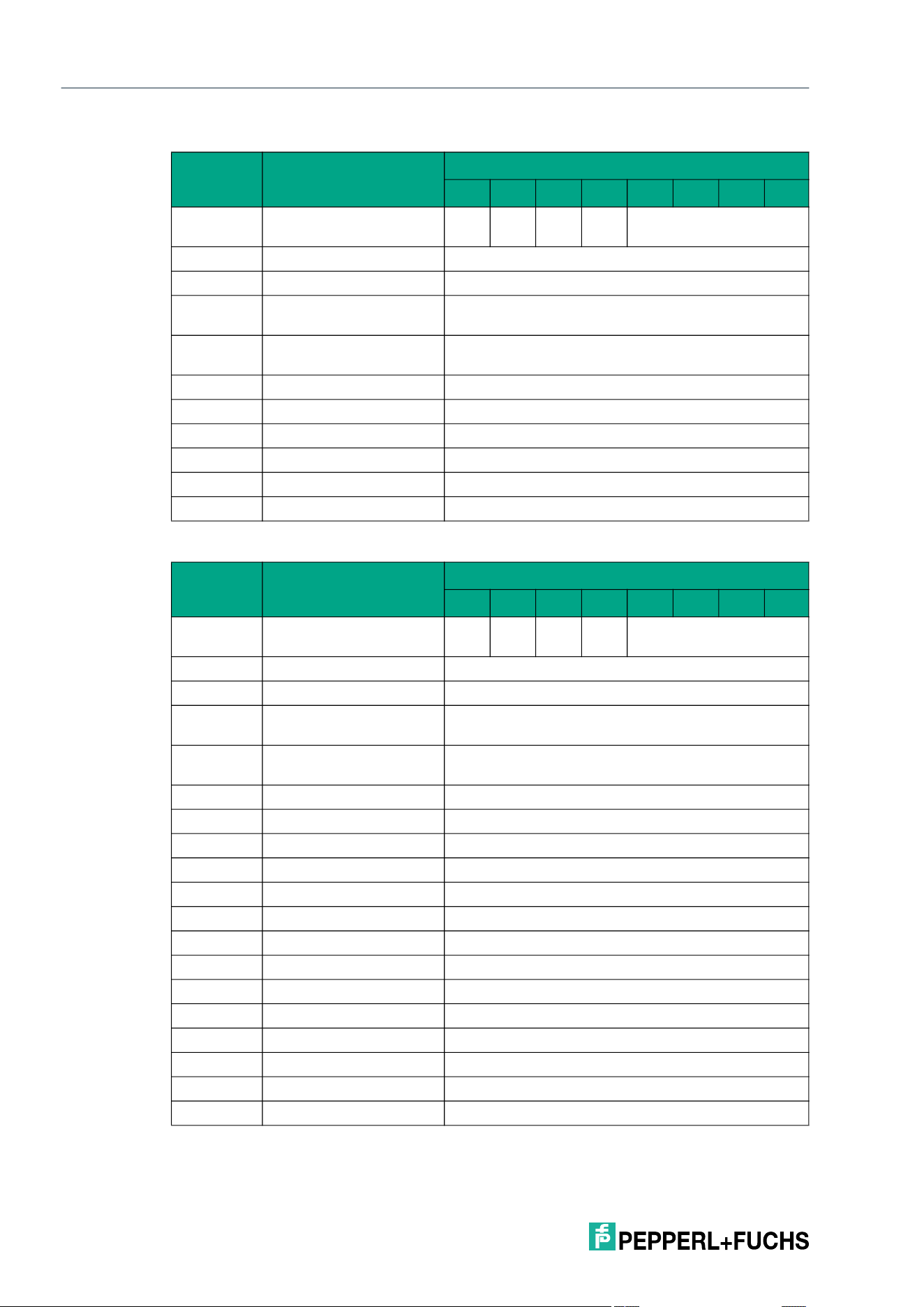
2026-05
74
IQT3 / IQT4 Series
ExpertMode
Response telegram 2 – status 16#0B (information frame mode
Response telegram 3 – status 16#05 (multiframe protocol)
Byte Content
Bit number
7 6 5 4 3 2 1 0
Byte 0 Control byte / frame
length
D
S
U
M
U
D
0 16#0
Byte 1 Frame length 16#09
Byte 2 Fragmentation counter 16#00
Byte 3 Telegram length (high
byte)
16#00
Byte 4 Telegram length (low
byte)
16#06
Byte 5 Command 16#48
Byte 6 Status 16#0B
Byte 7 Data 16#01 <Info Type>
Byte 8 Data <RSSI>
… Data 16#00
Byte 31 Data 16#00
Byte Content
Bit number
7 6 5 4 3 2 1 0
Byte 0 Control byte / frame
length
D
S
U
M
U
D
0 16#0
Byte 1 Frame length 16#11
Byte 2 Fragmentation counter 16#00
Byte 3 Telegram length (high
byte)
16#00
Byte 4 Telegram length (low
byte)
16#0E
Byte 5 Command 16#48
Byte 6 Status 16#05
Byte 7 Data 16#00 <Length UID in Bytes (High Byte)>
Byte 8 Data 16#08 <Length UID in Bytes (Low Byte)>
Byte 9 Data <UID Byte 1>
Byte 10 Data <UID Byte 2>
Byte 11 Data <UID Byte 3>
Byte 12 Data <UID Byte 4>
Byte 13 Data <UID Byte 5>
Byte 14 Data <UID Byte 6>
Byte 15 Data <UID Byte 7>
Byte 16 Data <UID Byte 8>
… Data 16#00
Byte 31 Data 16#00
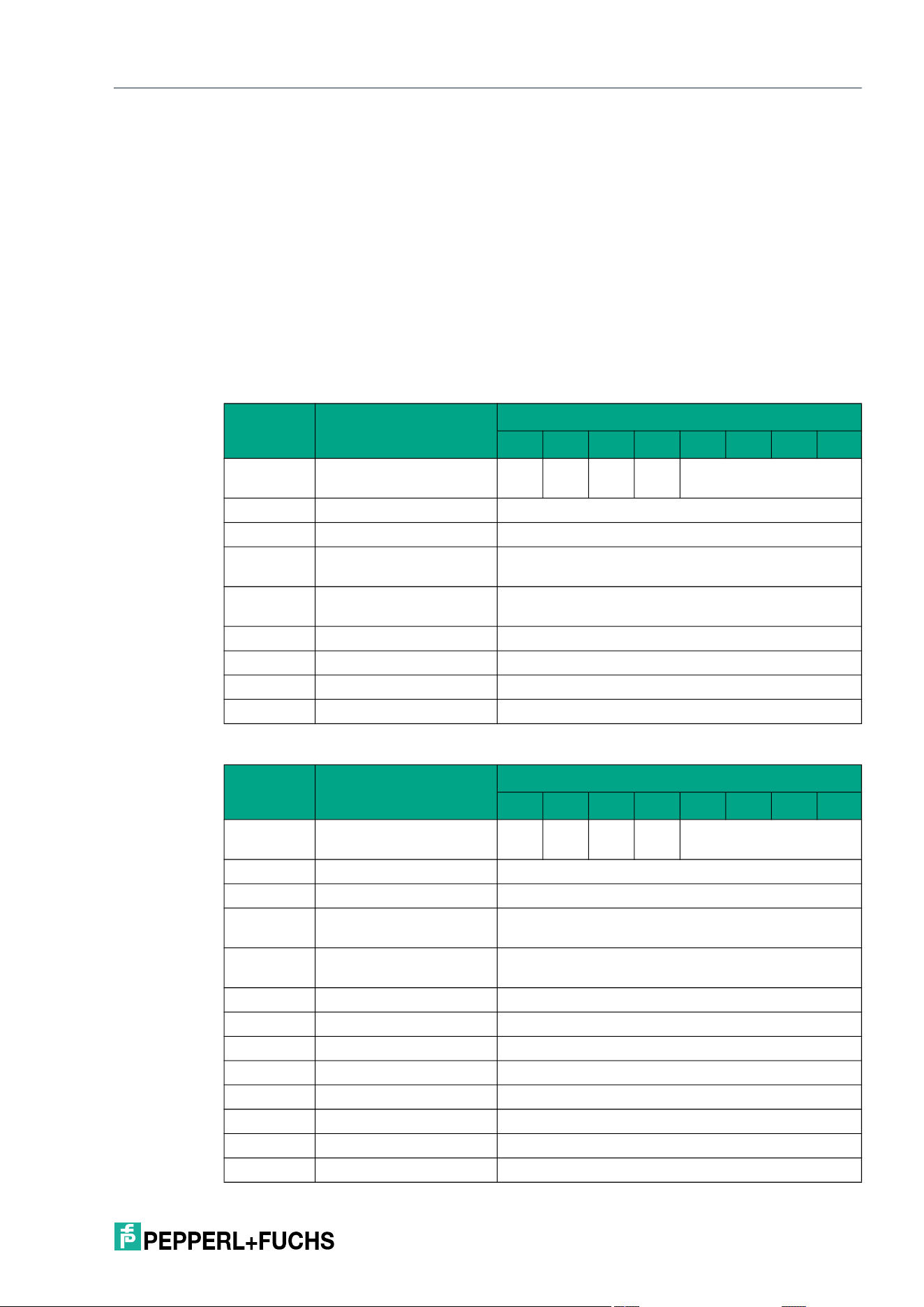
IQT3 / IQT4 Series
ExpertMode
2026-05
75
Single Get Configuration (SG)
The SG command has the command code 16#61 and performs a single read operation on the
configuration area of a tag within the sensing zone. This can be used to read the AFI or DSFID
of the tag.
The <Config Address> parameter defines the access to the configuration area and has the
value 16#00 or 16#30.
For each tag read, the information read is transmitted in a separate data telegram with the sta-
tus value 16#00. In addition, for each tag read, a further telegram with the status value 16#0B is
transmitted, which contains the RSSI value for the signal strength of the tag response.
The end of the command execution is indicated by an end telegram. The end telegram has the
status value 16#0F and contains the number of tags that were identified during execution of the
command.
Command telegram
Response telegram 1 – status 16#00 (long-form data format)
Byte Content
Bit number
7 6 5 4 3 2 1 0
Byte 0 Control byte / frame
length
D
S
U
M
U
D
0 16#0
Byte 1 Frame length 16#07
Byte 2 Fragmentation counter 16#00
Byte 3 Telegram length (high
byte)
16#00
Byte 4 Telegram length (low
byte)
16#04
Byte 5 Command 16#61
Byte 6 Command parameter 16#00 <Config Address>
Byte … Command parameter 16#00
Byte 31 Command parameter 16#00
Byte Content
Bit number
7 6 5 4 3 2 1 0
Byte 0 Control byte / frame
length
D
S
U
M
U
D
0 16#0
Byte 1 Frame length 16#20
Byte 2 Fragmentation counter 16#01
Byte 3 Telegram length (high
byte)
16#00
Byte 4 Telegram length (low
byte)
16#1E
Byte 5 Command 16#61
Byte 6 Status 16#00
Byte 7 Data 16#00 <Length UID in Bytes (High Byte)>
Byte 8 Data 16#08 <Length UID in Bytes (Low Byte)>
Byte 9 Data <UID Byte 1>
Byte 10 Data <UID Byte 2>
Byte 11 Data <UID Byte 3>
Byte 12 Data <UID Byte 4>
2026-05
76
IQT3 / IQT4 Series
ExpertMode
Response telegram 2 – status 16#00 (long-form data format)
Response telegram 3 – status 16#0B (information frame mode)
Byte 13 Data <UID Byte 5>
Byte 14 Data <UID Byte 6>
Byte 15 Data <UID Byte 7>
Byte 16 Data <UID Byte 8>
Byte 17 Data 16#00
Byte 18 Data 16#0E
Byte 19 Data <Info Flags>
Byte 20 Data <UID Byte 8>
Byte 21 Data <UID Byte 7>
Byte 22 Data <UID Byte 6>
Byte 23 Data <UID Byte 5>
Byte 24 Data <UID Byte 4>
Byte 25 Data <UID Byte 3>
Byte 26 Data <UID Byte 2>
Byte 27 Data <UID Byte 1>
Byte 28 Data <DSFID>
Byte 29 Data <AFI>
Byte 30 Data <VICC Memory Size (Number of Blocks -1)>
Byte 31 Data <VICC Memory Size (Block Size -1)>
Byte Content
Bit number
7 6 5 4 3 2 1 0
Byte 0 Control byte / frame
length
D
S
U
M
U
D
0 16#0
Byte 1 Frame length 16#04
Byte 2 Fragmentation counter 16#00
Byte 3 Data <IC Reference>
… Data 16#00
Byte 31 Data 16#00
Byte Content
Bit number
7 6 5 4 3 2 1 0
Byte 0 Control byte / frame
length
D
S
U
M
U
D
0 16#0
Byte 1 Frame length 16#09
Byte 2 Fragmentation counter 16#00
Byte 3 Telegram length (high
byte)
16#00
Byte 4 Telegram length (low
byte)
16#06
Byte Content
Bit number
7 6 5 4 3 2 1 0
IQT3 / IQT4 Series
ExpertMode
2026-05
77
Response telegram 4 – status 16#0F (long-form data format):
Enhanced Get Configuration (EG)
The EG command has the command code 16#68 and performs a permanent read operation on
the configuration area of a tag within the sensing zone. This can be used to read the AFI or
DSFID of the tag.
The <Config Address> parameter defines the access to the configuration area and has the
value 16#00 or 16#30.
For each tag read, the information read is transmitted in a separate data telegram with the sta-
tus value 16#00. In addition, for each tag read, a further telegram with the status value 16#0B is
transmitted, which contains information on the signal strength of the tag response (RSSI value).
A tag leaving the sensing zone is indicated by a telegram containing the UID of the tag. This
telegram has the status value 16#05.
A Quit command stops the command execution.
Byte 5 Command 16#61
Byte 6 Status 16#0B
Byte 7 Data 16#01 <Info Type>
Byte 8 Data <RSSI>
… Data 16#00
Byte 31 Data 16#00
Byte Content
Bit number
7 6 5 4 3 2 1 0
Byte 0 Control byte / frame
length
D
S
U
M
U
D
0 16#0
Byte 1 Frame length 16#0B
Byte 2 Fragmentation counter 16#00
Byte 3 Telegram length (high
byte)
16#00
Byte 4 Telegram length (low
byte)
16#08
Byte 5 Command 16#61
Byte 6 Status 16#0F
Byte 7 Data <Number of Tags Byte 1>
Byte 8 Data <Number of Tags Byte 2>
Byte 9 Data <Number of Tags Byte 3>
Byte 10 Data <Number of Tags Byte 4>
… Data 16#00
Byte 31 Data 16#00
Byte Content
Bit number
7 6 5 4 3 2 1 0

2026-05
78
IQT3 / IQT4 Series
ExpertMode
Command telegram
Response telegram 1 – status 16#00 (long-form data format)
Byte Content
Bit number
7 6 5 4 3 2 1 0
Byte 0 Control byte / frame
length
D
S
U
M
U
D
0 16#0
Byte 1 Frame length 16#07
Byte 2 Fragmentation counter 16#00
Byte 3 Telegram length (high
byte)
16#00
Byte 4 Telegram length (low
byte)
16#04
Byte 5 Command 16#68
Byte 6 Command parameter 16#00 <Config Address>
Byte … Command parameter 16#00
Byte 31 Command parameter 16#00
Byte Content
Bit number
7 6 5 4 3 2 1 0
Byte 0 Control byte / frame
length
D
S
U
M
U
D
0 16#0
Byte 1 Frame length 16#20
Byte 2 Fragmentation counter 16#00
Byte 3 Telegram length (high
byte)
16#00
Byte 4 Telegram length (low
byte)
16#1E
Byte 5 Command 16#68
Byte 6 Status 16#00
Byte 7 Data 16#00 <Length UID in Bytes (High Byte)>
Byte 8 Data 16#08 <Length UID in Bytes (Low Byte)>
Byte 9 Data <UID Byte 1>
Byte 10 Data <UID Byte 2>
Byte 11 Data <UID Byte 3>
Byte 12 Data <UID Byte 4>
Byte 13 Data <UID Byte 5>
Byte 14 Data <UID Byte 6>
Byte 15 Data <UID Byte 7>
Byte 16 Data <UID Byte 8>
Byte 17 Data 16#00
Byte 18 Data 16#0E
Byte 19 Data <Info Flags>
Byte 20 Data <UID Byte 8>
Byte 21 Data <UID Byte 7>
Byte 22 Data <UID Byte 6>
IQT3 / IQT4 Series
ExpertMode
2026-05
79
Response telegram 2 – status 16#00 (long-form data format)
Response telegram 3 – status 16#0B (information frame mode)
Byte 23 Data <UID Byte 5>
Byte 24 Data <UID Byte 4>
Byte 25 Data <UID Byte 3>
Byte 26 Data <UID Byte 2>
Byte 27 Data <UID Byte 1>
Byte 28 Data <DSFID>
Byte 29 Data <AFI>
Byte 30 Data <VICC Memory Size (Number of Blocks -1)>
Byte 31 Data <VICC Memory Size (Block Size -1)>
Byte Content
Bit number
7 6 5 4 3 2 1 0
Byte 0 Control byte / frame
length
D
S
U
M
U
D
0 16#0
Byte 1 Frame length 16#09
Byte 2 Fragmentation counter 16#00
Byte 3 Data <IC Reference>
… Data 16#00
Byte 31 Data 16#00
Byte Content
Bit number
7 6 5 4 3 2 1 0
Byte 0 Control byte / frame
length
D
S
U
M
U
D
0 16#0
Byte 1 Frame length 16#09
Byte 2 Fragmentation counter 16#00
Byte 3 Telegram length (high
byte)
16#00
Byte 4 Telegram length (low
byte)
16#06
Byte 5 Command 16#68
Byte 6 Status 16#0B
Byte 7 Data 16#01 <Info Type>
Byte 8 Data <RSSI>
… Data 16#00
Byte 31 Data 16#00
Byte Content
Bit number
7 6 5 4 3 2 1 0
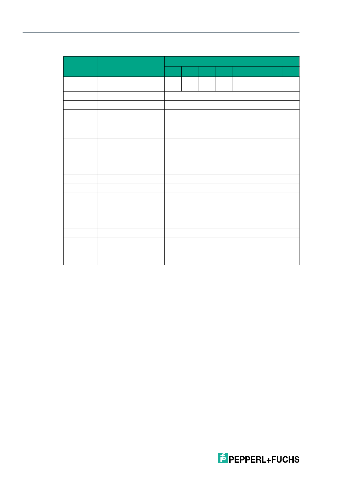
2026-05
80
IQT3 / IQT4 Series
ExpertMode
Response telegram 4 – status 16#05 (long-form data format)
Single Set Configuration (SC)
The SC command has the command code 16#12 and performs a single write operation to the
AFI or DSFID in the configuration area of a tag within the sensing zone.
The <Config Address> parameter specifies whether the AFI (16#00 or 16#30) or the DSFID
(16#01 or 16#31) is to be written. The <Lock> parameter specifies whether the AFI or DSFID is
to be written without (16#00 or 16#30) or with write protection (16#01 or 16#31).
If the AFI or DSFID is already read-only, a rewrite or write-protect operation has a response with
status 5.
A separate data telegram with the status value 16#00 indicates a successful write operation for
each tag written. The data telegram contains the UID of the tag to which the user data area was
written. In addition, for each tag written, a further telegram with the status value 16#0B is trans-
mitted, which contains information on the signal strength of the tag response (RSSI value).
The end of the command execution is indicated by an end telegram. The end telegram has the
status value 16#0F and contains the number of tags that were written during execution of the
command.
Byte Content
Bit number
7 6 5 4 3 2 1 0
Byte 0 Control byte / frame
length
D
S
U
M
U
D
0 16#0
Byte 1 Frame length 16#11
Byte 2 Fragmentation counter 16#00
Byte 3 Telegram length (high
byte)
16#00
Byte 4 Telegram length (low
byte)
16#0E
Byte 5 Command 16#68
Byte 6 Status 16#05
Byte 7 Data 16#00 <Length UID in Bytes (High Byte)>
Byte 8 Data 16#08 <Length UID in Bytes (Low Byte)>
Byte 9 Data <UID Byte 1>
Byte 10 Data <UID Byte 2>
Byte 11 Data <UID Byte 3>
Byte 12 Data <UID Byte 4>
Byte 13 Data <UID Byte 5>
Byte 14 Data <UID Byte 6>
Byte 15 Data <UID Byte 7>
Byte 16 Data <UID Byte 8>
… Data 16#00
Byte 31 Data 16#00
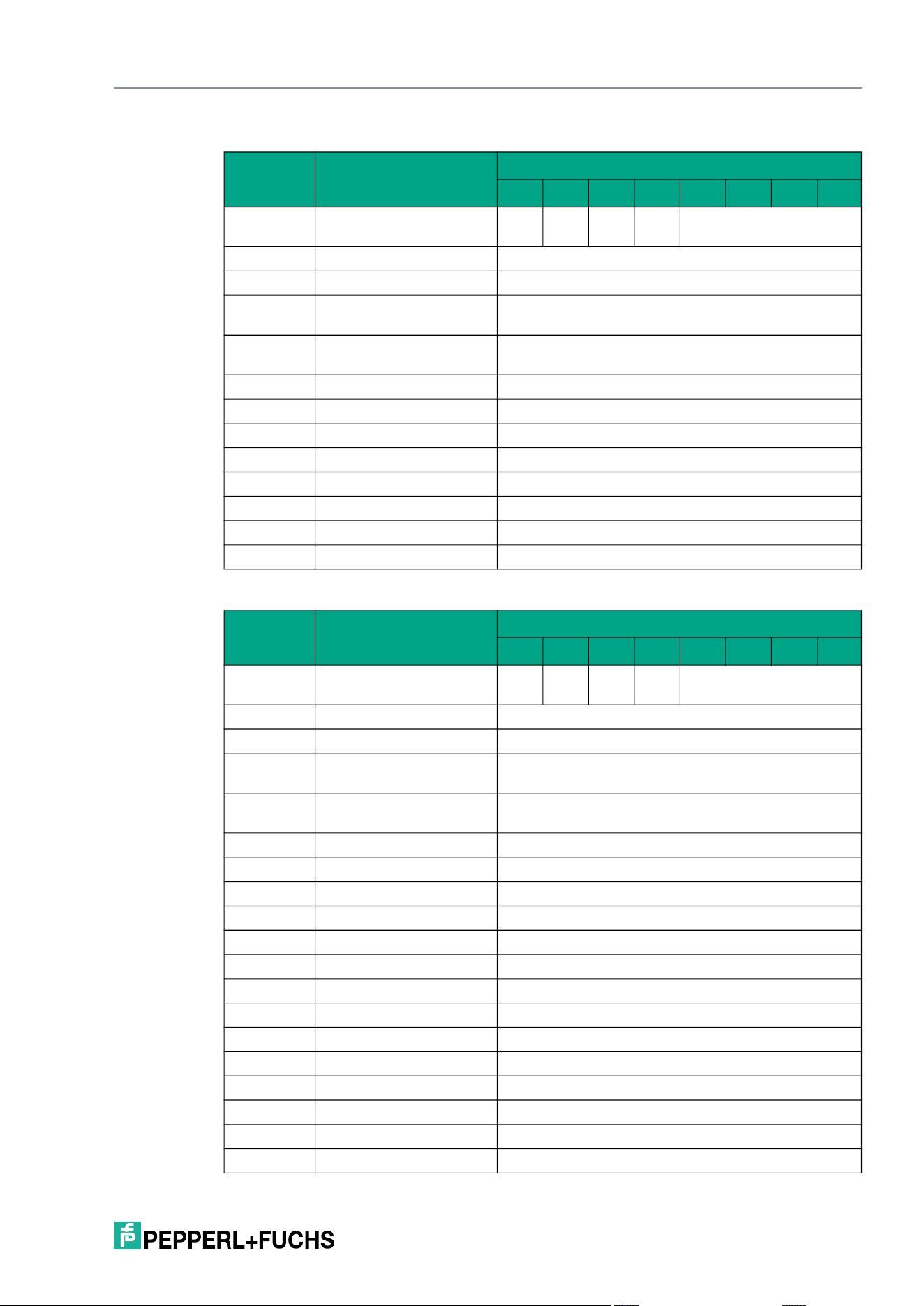
IQT3 / IQT4 Series
ExpertMode
2026-05
81
Command telegram
Response telegram 1 – status 16#00 (long-form data format)
Byte Content
Bit number
7 6 5 4 3 2 1 0
Byte 0 Control byte / frame
length
D
S
U
M
U
D
0 16#0
Byte 1 Frame length 16#0B
Byte 2 Fragmentation counter 16#00
Byte 3 Telegram length (high
byte)
16#00
Byte 4 Telegram length (low
byte)
16#08
Byte 5 Command 16#12
Byte 6 Command parameter 16#00 <Config Address>
Byte 7 Command parameter <Lock>
Byte 8 Command parameter <DSFID / AFI>
Byte 9 Command parameter 16#00 (always)
Byte 10 Command parameter 16#00 (always)
… Command parameter 16#00
Byte 31 Command parameter 16#00
Byte Content
Bit number
7 6 5 4 3 2 1 0
Byte 0 Control byte / frame
length
D
S
U
M
U
D
0 16#0
Byte 1 Frame length 16#11
Byte 2 Fragmentation counter 16#00
Byte 3 Telegram length (high
byte)
16#00
Byte 4 Telegram length (low
byte)
16#0E
Byte 5 Command 16#12
Byte 6 Status 16#00
Byte 7 Data 16#00 <Length UID in Bytes (High Byte)>
Byte 8 Data 16#08 <Length UID in Bytes (Low Byte)>
Byte 9 Data <UID Byte 1>
Byte 10 Data <UID Byte 2>
Byte 11 Data <UID Byte 3>
Byte 12 Data <UID Byte 4>
Byte 13 Data <UID Byte 5>
Byte 14 Data <UID Byte 6>
Byte 15 Data <UID Byte 7>
Byte 16 Data <UID Byte 8>
… Data 16#00
Byte 31 Data 16#00
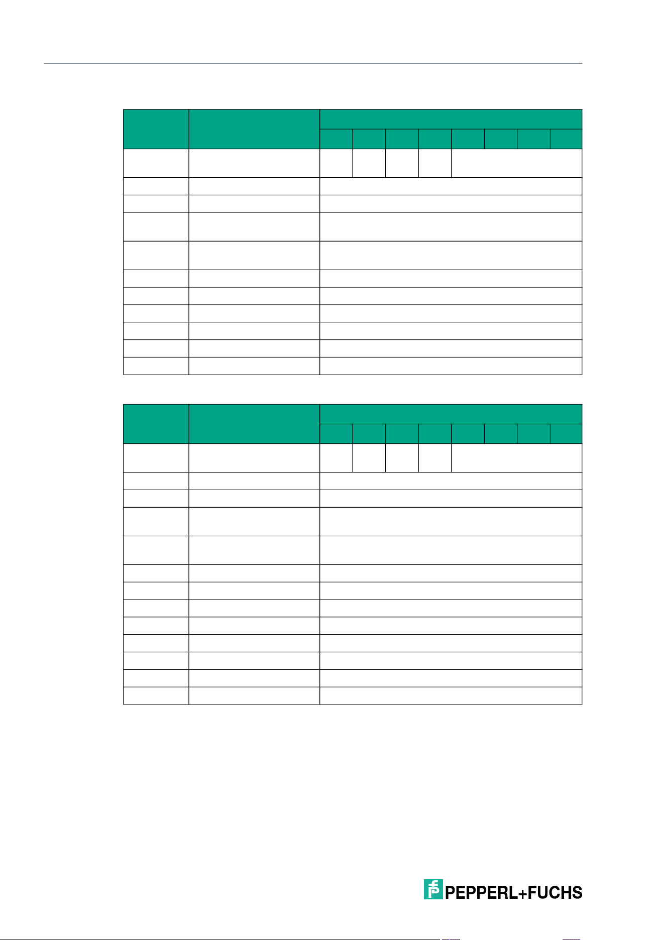
2026-05
82
IQT3 / IQT4 Series
ExpertMode
Response telegram 2 – status 16#0B (information frame mode
Response telegram 3 – status 16#0F (long-form data format)
Enhanced Set Configuration (EC)
The EC command has the command code 16#66 and performs a permanent write operation
on the AFI or DSFID in the configuration area of a tag within the sensing zone.
The <Config Address> parameter specifies whether the AFI (16#00 or 16#30) or the DSFID
(16#01 or 16#31) is to be written. The <Lock> parameter specifies whether the AFI or DSFID is
to be written without (16#00 or 16#30) or with write protection (16#01 or 16#31). The read/write
device constantly attempts to write the AFI or DSFID in the configuration area.
If the AFI or DSFID is already read-only, a rewrite or write-protect operation has a response with
status 5.
Byte Content
Bit number
7 6 5 4 3 2 1 0
Byte 0 Control byte / frame
length
D
S
U
M
U
D
0 16#0
Byte 1 Frame length 16#09
Byte 2 Fragmentation counter 16#00
Byte 3 Telegram length (high
byte)
16#00
Byte 4 Telegram length (low
byte)
16#06
Byte 5 Command 16#12
Byte 6 Status 16#0B
Byte 7 Data 16#01 <Info Type>
Byte 8 Data <RSSI>
… Data 16#00
Byte 31 Data 16#00
Byte Content
Bit number
7 6 5 4 3 2 1 0
Byte 0 Control byte / frame
length
D
S
U
M
U
D
0 16#0
Byte 1 Frame length 16#0B
Byte 2 Fragmentation counter 16#00
Byte 3 Telegram length (high
byte)
16#00
Byte 4 Telegram length (low
byte)
16#08
Byte 5 Command 16#12
Byte 6 Status 16#0F
Byte 7 Data <Number of Tags Byte 1>
Byte 8 Data <Number of Tags Byte 2>
Byte 9 Data <Number of Tags Byte 3>
Byte 10 Data <Number of Tags Byte 4>
… Data 16#00
Byte 31 Data 16#00
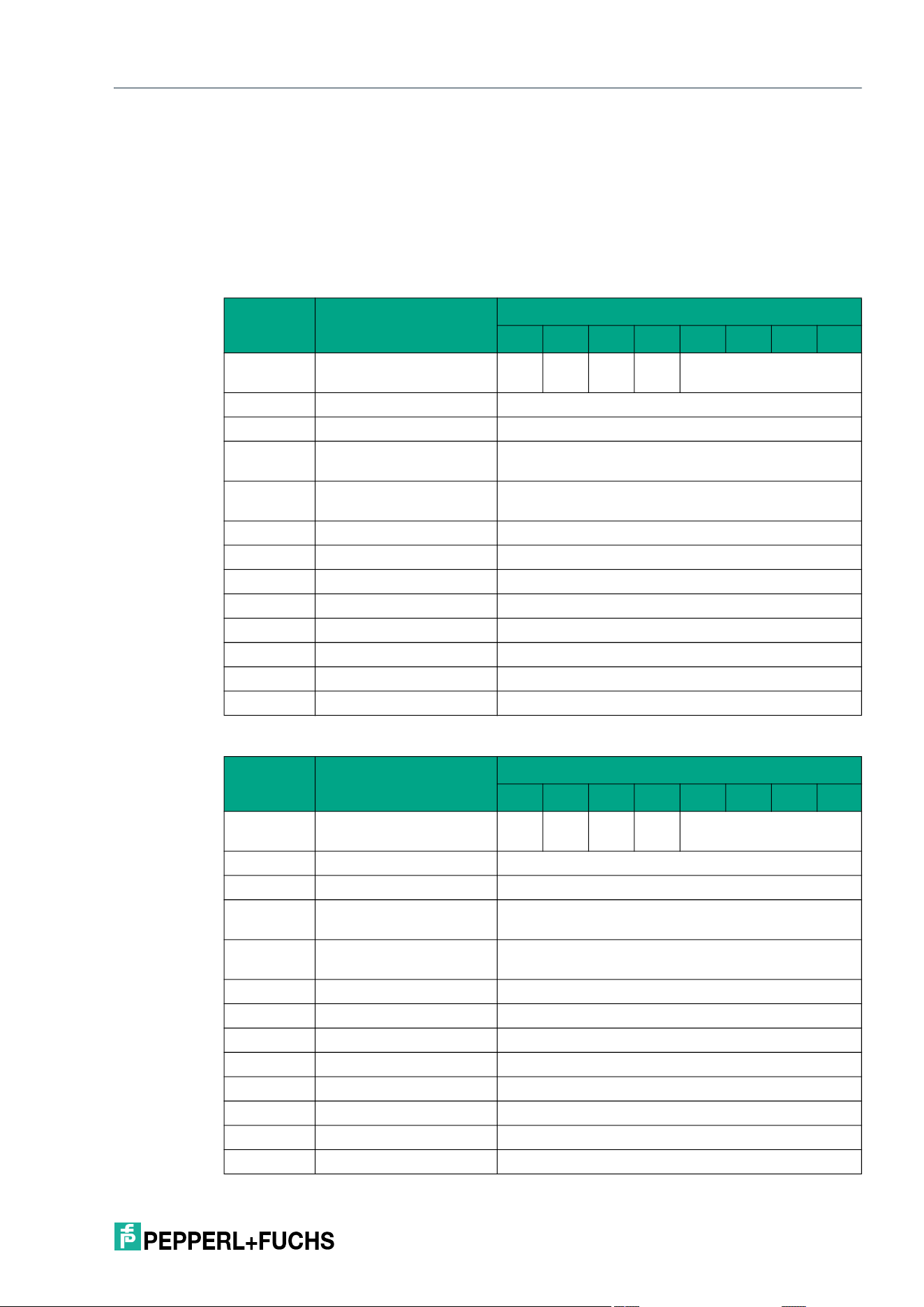
IQT3 / IQT4 Series
ExpertMode
2026-05
83
A separate data telegram with the status value 16#00 indicates a successful write operation for
each tag written. The data telegram contains the UID of the tag to which the user data area was
written. In addition, for each tag written, a further telegram with the status value 16#0B is trans-
mitted, which contains information on the signal strength of the tag response (RSSI value).
A tag leaving the sensing zone is indicated by a telegram containing the UID of the tag. This
telegram has the status value 16#05.
A Quit command stops the command execution.
Command telegram
Response telegram 1 – status 16#00 (long-form data format)
Byte Content
Bit number
7 6 5 4 3 2 1 0
Byte 0 Control byte / frame
length
D
S
U
M
U
D
0 16#0
Byte 1 Frame length 16#0B
Byte 2 Fragmentation counter 16#00
Byte 3 Telegram length (high
byte)
16#00
Byte 4 Telegram length (low
byte)
16#08
Byte 5 Command 16#66
Byte 6 Command parameter 16#00 <Config Address>
Byte 7 Command parameter <Lock>
Byte 8 Command parameter <DSFID / AFI>
Byte 9 Command parameter 16#00 (always)
Byte 10 Command parameter 16#00 (always)
… Command parameters 16#00
Byte 31 Command parameter 16#00
Byte Content
Bit number
7 6 5 4 3 2 1 0
Byte 0 Control byte / frame
length
D
S
U
M
U
D
0 16#0
Byte 1 Frame length 16#11
Byte 2 Fragmentation counter 16#00
Byte 3 Telegram length (high
byte)
16#00
Byte 4 Telegram length (low
byte)
16#0E
Byte 5 Command 16#66
Byte 6 Status 16#00
Byte 7 Data 16#00 <Length UID in Bytes (High Byte)>
Byte 8 Data 16#08 <Length UID in Bytes (Low Byte)>
Byte 9 Data <UID Byte 1>
Byte 10 Data <UID Byte 2>
Byte 11 Data <UID Byte 3>
Byte 12 Data <UID Byte 4>
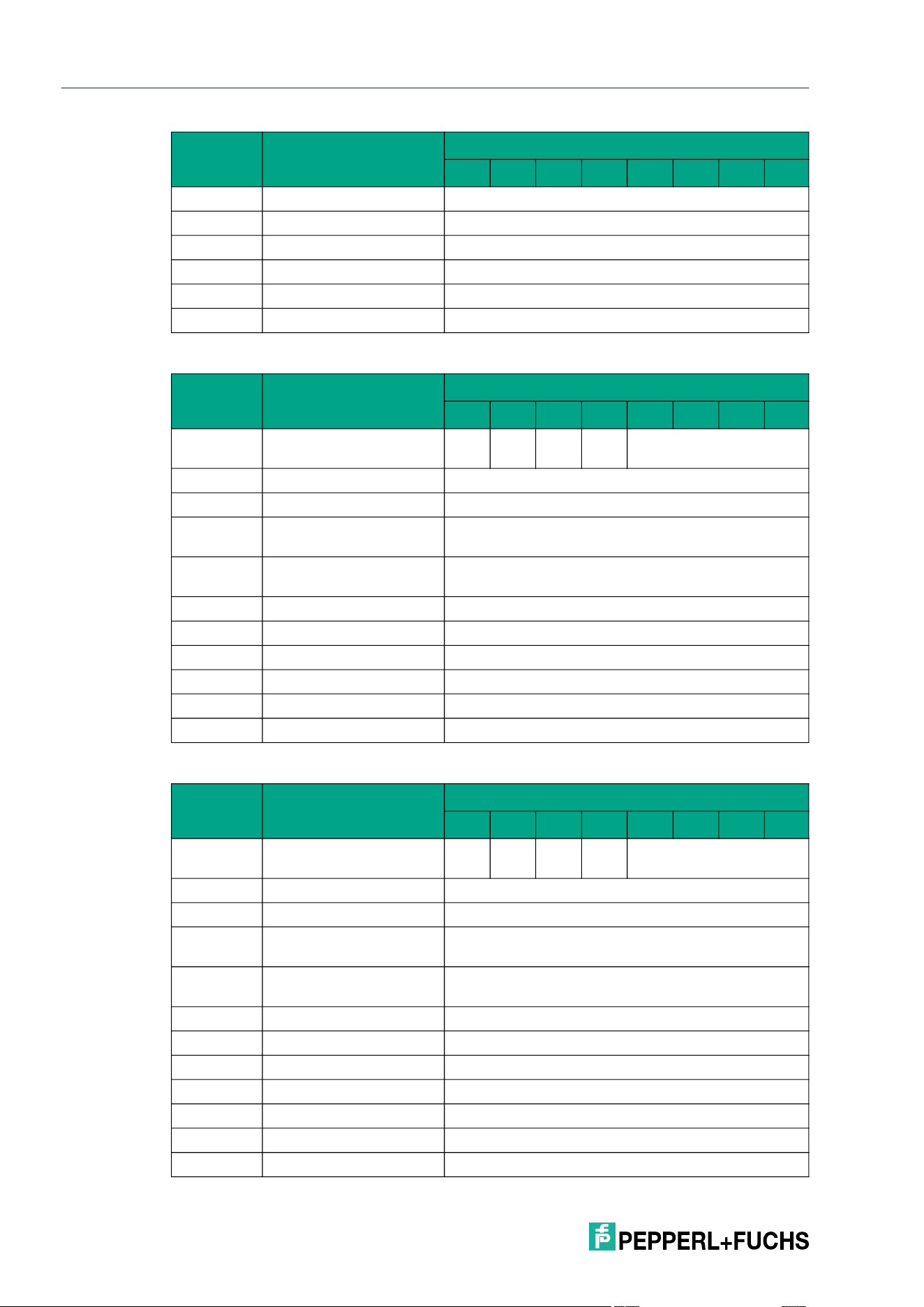
2026-05
84
IQT3 / IQT4 Series
ExpertMode
Response telegram 2 – status 16#0B (information frame mode
Response telegram 3 – status 16#05 (long-form data format)
Byte 13 Data <UID Byte 5>
Byte 14 Data <UID Byte 6>
Byte 15 Data <UID Byte 7>
Byte 16 Data <UID Byte 8>
… Data 16#00
Byte 31 Data 16#00
Byte Content
Bit number
7 6 5 4 3 2 1 0
Byte 0 Control byte / frame
length
D
S
U
M
U
D
0 16#0
Byte 1 Frame length 16#09
Byte 2 Fragmentation counter 16#00
Byte 3 Telegram length (high
byte)
16#00
Byte 4 Telegram length (low
byte)
16#06
Byte 5 Command 16#66
Byte 6 Status 16#0B
Byte 7 Data 16#01 <Info Type>
Byte 8 Data <RSSI>
… Data 16#00
Byte 31 Data 16#00
Byte Content
Bit number
7 6 5 4 3 2 1 0
Byte 0 Control byte / frame
length
D
S
U
M
U
D
0 16#0
Byte 1 Frame length 16#11
Byte 2 Fragmentation counter 16#00
Byte 3 Telegram length (high
byte)
16#00
Byte 4 Telegram length (low
byte)
16#0E
Byte 5 Command 16#66
Byte 6 Status 16#05
Byte 7 Data 16#00 <Length UID in Bytes (High Byte)>
Byte 8 Data 16#08 <Length UID in Bytes (Low Byte)>
Byte 9 Data <UID Byte 1>
Byte 10 Data <UID Byte 2>
Byte 11 Data <UID Byte 3>
Byte Content
Bit number
7 6 5 4 3 2 1 0
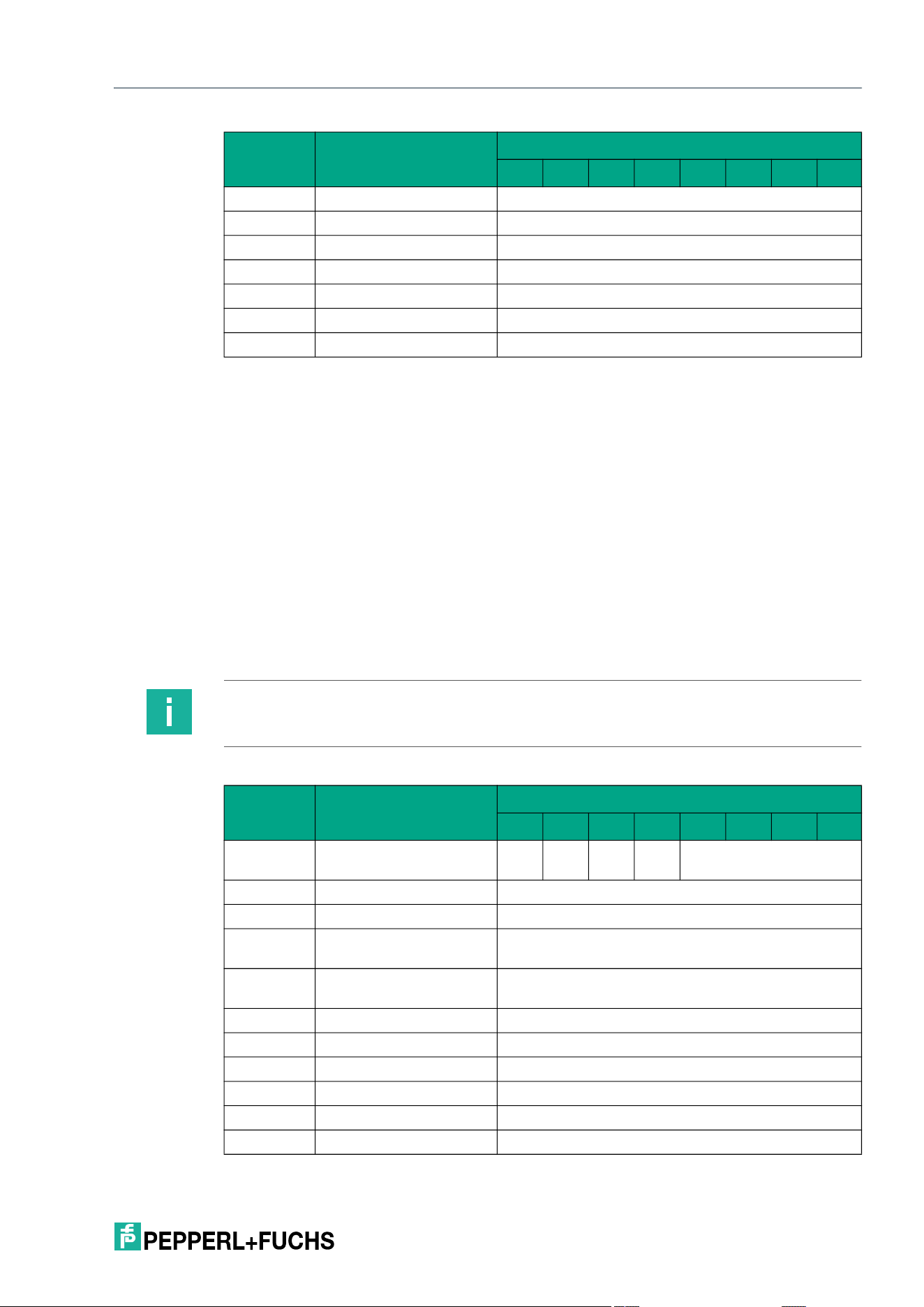
IQT3 / IQT4 Series
ExpertMode
2026-05
85
Fill Tag (S#)
The S# command has the command code 16#AA and performs a single write operation to the
user data area of a tag within the sensing zone.
The <Start Address> parameter specifies the start address within the user data area. The value
of <Start Address> is based on bytes. Only multiples of the memory block size can be parame-
terized. <Number of Bytes> defines the number of bytes to be written. The number of bytes
must also be a multiple of the memory block size. The <Fill Sign> parameter specifies the fill
sign to be written.
A separate data telegram with the status value 16#00 indicates a successful write operation for
each tag written. The data telegram contains the UID of the tag to which the user data area was
written. In addition, for each tag written, a further telegram with the status value 16#0B is trans-
mitted, which contains information on the signal strength of the tag response (RSSI value).
The end of the command execution is indicated by an end telegram. The end telegram has the
status value 16#0F and contains the number of tags that were written during execution of the
command.
Command telegram
Byte 12 Data <UID Byte 4>
Byte 13 Data <UID Byte 5>
Byte 14 Data <UID Byte 6>
Byte 15 Data <UID Byte 7>
Byte 16 Data <UID Byte 8>
… Data 16#00
Byte 31 Data 16#00
Byte Content
Bit number
7 6 5 4 3 2 1 0
Note
If <Number of Bytes> is set to 16#0000, the tag is filled from <Start Address> up to the end of
the tag.
Byte Content
Bit number
7 6 5 4 3 2 1 0
Byte 0 Control byte / frame
length
D
S
U
M
U
D
0 16#0
Byte 1 Frame length 16#0B
Byte 2 Fragmentation counter 16#00
Byte 3 Telegram length (high
byte)
16#00
Byte 4 Telegram length (low
byte)
16#08
Byte 5 Command 16#AA
Byte 6 Command parameter 16#00 <Start Address (High Byte)>
Byte 7 Command parameter 16#00 <Start Address (Low Byte)>
Byte 8 Command parameter 16#00 <Number of Bytes (High Byte)>
Byte 9 Command parameter 16#04 <Number of Bytes (Low Byte)>
Byte 10 Command parameter <Fill Sign>
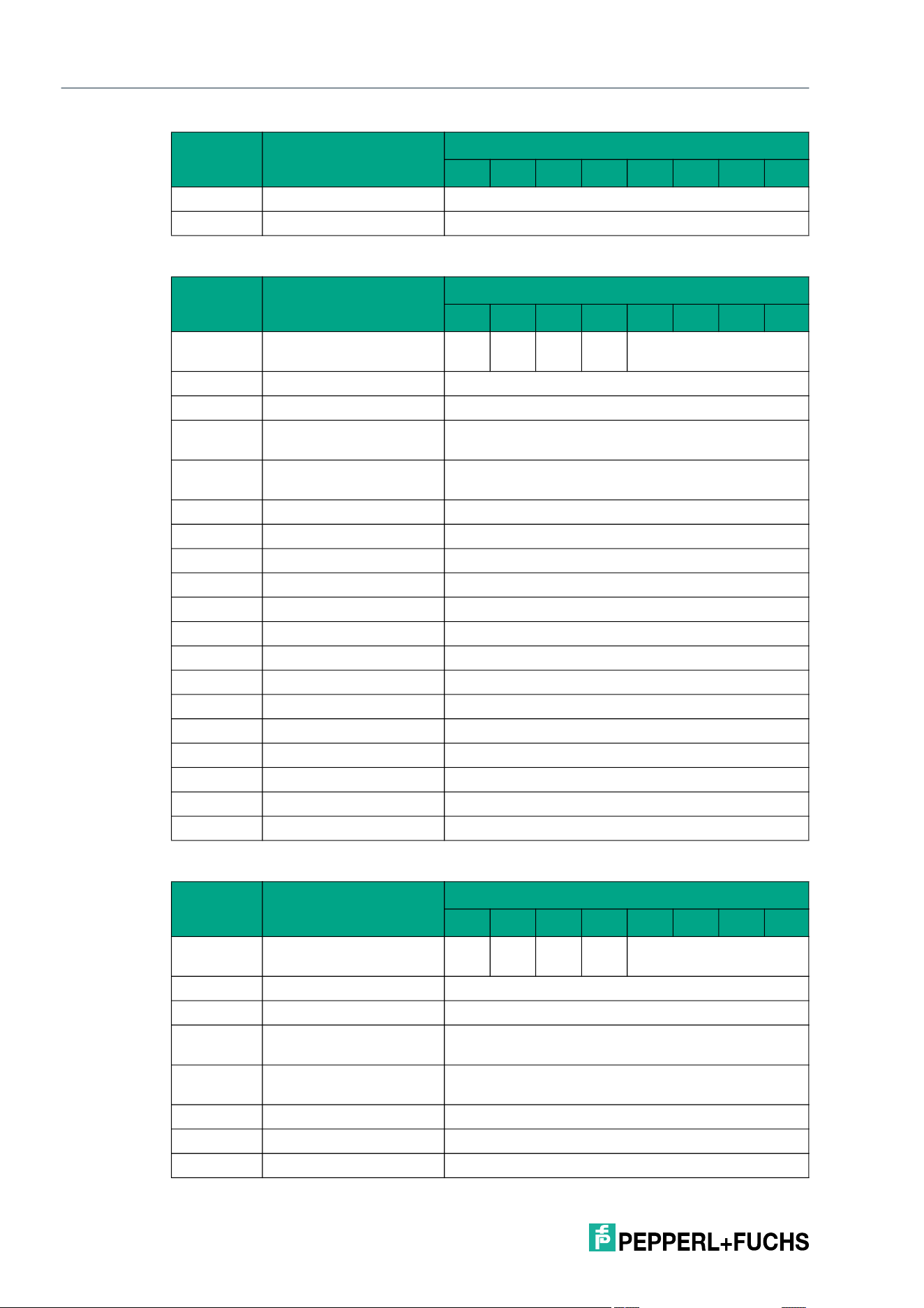
2026-05
86
IQT3 / IQT4 Series
ExpertMode
Response telegram 1 – status 16#00 (long-form data format)
Response telegram 2 – status 16#0B (information frame mode
… Command parameters 16#00
Byte 31 Command parameter 16#00
Byte Content
Bit number
7 6 5 4 3 2 1 0
Byte 0 Control byte / frame
length
D
S
U
M
U
D
0 16#0
Byte 1 Frame length 16#11
Byte 2 Fragmentation counter 16#00
Byte 3 Telegram length (high
byte)
16#00
Byte 4 Telegram length (low
byte)
16#0E
Byte 5 Command 16#AA
Byte 6 Status 16#00
Byte 7 Data 16#00 <Length UID in Bytes (High Byte)>
Byte 8 Data 16#08 <Length UID in Bytes (Low Byte)>
Byte 9 Data <UID Byte 1>
Byte 10 Data <UID Byte 2>
Byte 11 Data <UID Byte 3>
Byte 12 Data <UID Byte 4>
Byte 13 Data <UID Byte 5>
Byte 14 Data <UID Byte 6>
Byte 15 Data <UID Byte 7>
Byte 16 Data <UID Byte 8>
… Data 16#00
Byte 31 Data 16#00
Byte Content
Bit number
7 6 5 4 3 2 1 0
Byte 0 Control byte / frame
length
D
S
U
M
U
D
0 16#0
Byte 1 Frame length 16#09
Byte 2 Fragmentation counter 16#00
Byte 3 Telegram length (high
byte)
16#00
Byte 4 Telegram length (low
byte)
16#06
Byte 5 Command 16#AA
Byte 6 Status 16#0B
Byte 7 Data 16#01 <Info Type>
Byte Content
Bit number
7 6 5 4 3 2 1 0
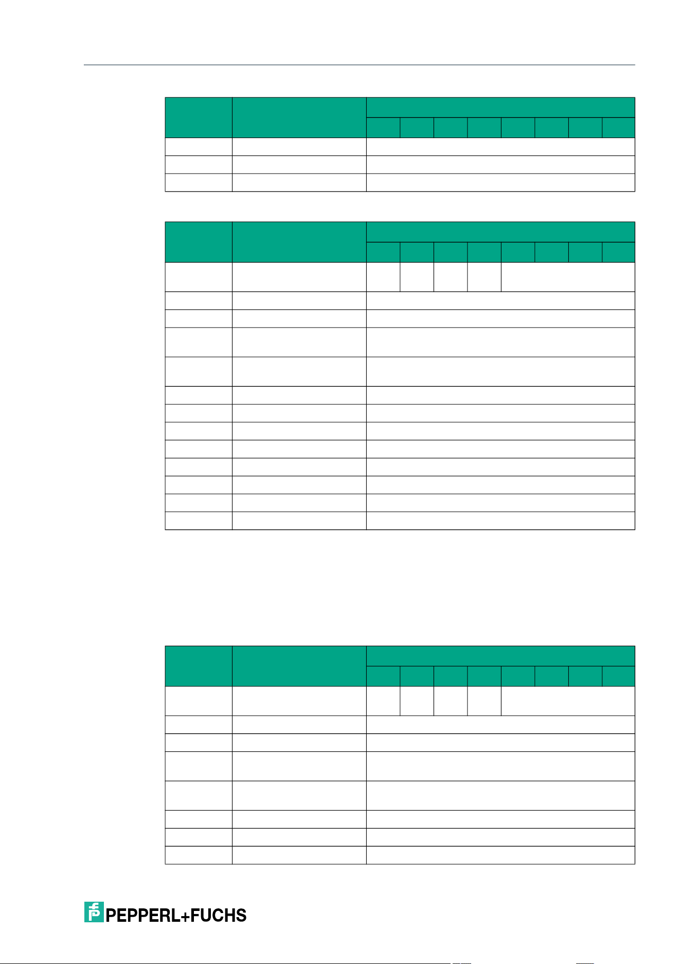
IQT3 / IQT4 Series
ExpertMode
2026-05
87
Response telegram 3 – status 16#0F (long-form data format)
Selective Single Read Fixcode (XSF)
The XSF command has the command code 16#E8. In principle, the command functions in
exactly the same way as the SF command (16#01), but is only executed for a selected tag.
The parameters <UID Mask Byte 1> to <UID Mask Byte 8> are used to specify the UID of the
selected tag. <Length UID Mask in Bit> specifies the length of the UID in bits.
Command telegram (8 byte UID mask)
Byte 8 Data <RSSI>
… Data 16#00
Byte 31 Data 16#00
Byte Content
Bit number
7 6 5 4 3 2 1 0
Byte 0 Control byte / frame
length
D
S
U
M
U
D
0 16#0
Byte 1 Frame length 16#0B
Byte 2 Fragmentation counter 16#00
Byte 3 Telegram length (high
byte)
16#00
Byte 4 Telegram length (low
byte)
16#08
Byte 5 Command 16#AA
Byte 6 Status 16#0F
Byte 7 Data <Number of Tags Byte 1>
Byte 8 Data <Number of Tags Byte 2>
Byte 9 Data <Number of Tags Byte 3>
Byte 10 Data <Number of Tags Byte 4>
… Data 16#00
Byte 31 Data 16#00
Byte Content
Bit number
7 6 5 4 3 2 1 0
Byte 0 Control byte / frame
length
D
S
U
M
U
D
0 16#0
Byte 1 Frame length 16#10
Byte 2 Fragmentation counter 16#00
Byte 3 Telegram length (high
byte)
16#00
Byte 4 Telegram length (low
byte)
16#0D
Byte 5 Command 16#E8
Byte 6 Command parameter 16#00 <Length UID Mask in Bit (High Byte)>
Byte 7 Command parameter 16#40 <Length UID Mask in Bit (Low Byte)>
Byte Content
Bit number
7 6 5 4 3 2 1 0
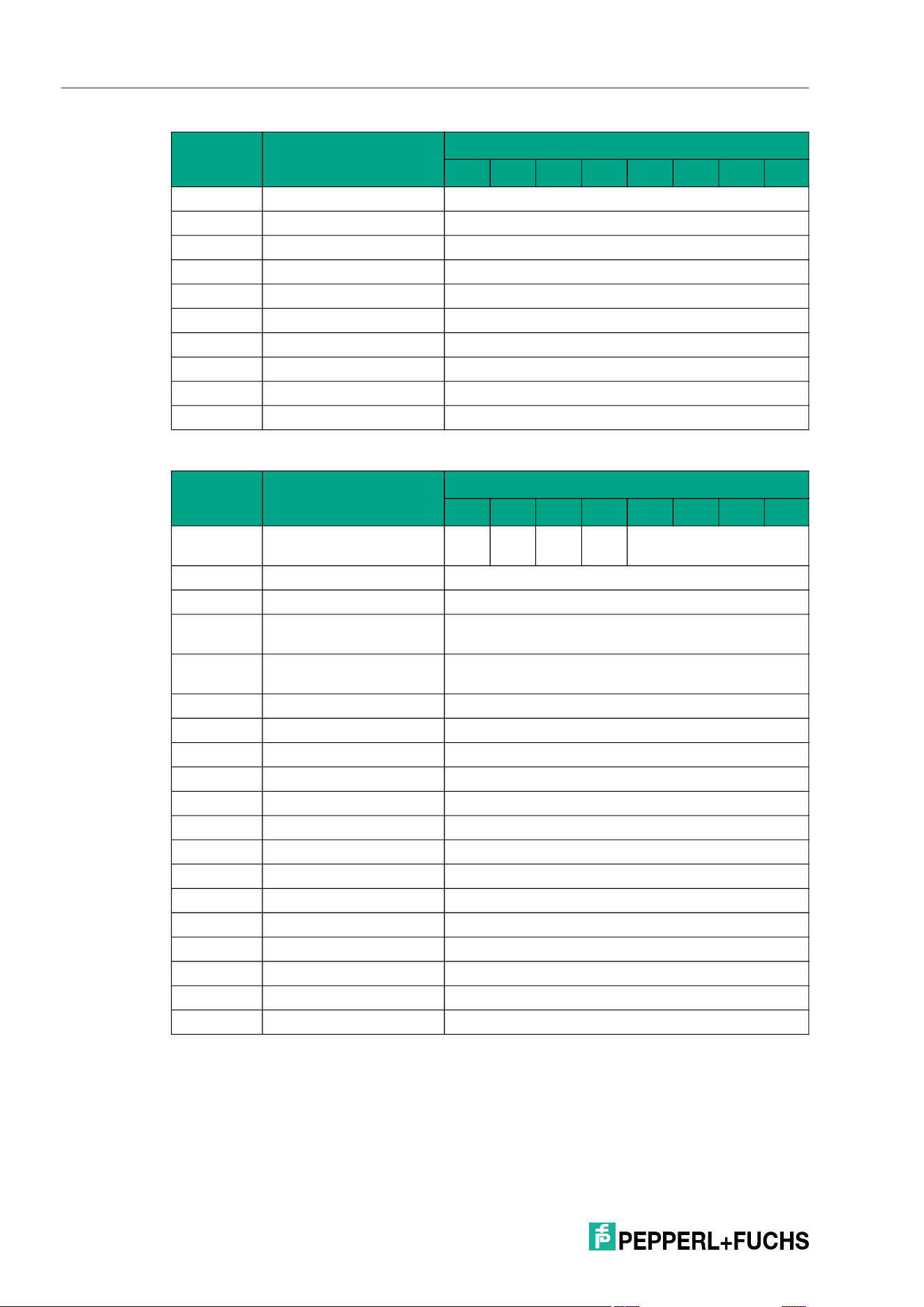
2026-05
88
IQT3 / IQT4 Series
ExpertMode
Response telegram 1 – status 16#00 (long-form data format)
Byte 8 Command parameter <UID Mask Byte 1>
Byte 9 Command parameter <UID Mask Byte 2>
Byte 10 Command parameter <UID Mask Byte 3>
Byte 11 Command parameter <UID Mask Byte 4>
Byte 12 Command parameter <UID Mask Byte 5>
Byte 13 Command parameter <UID Mask Byte 6>
Byte 14 Command parameter <UID Mask Byte 7>
Byte 15 Command parameter <UID Mask Byte 8>
… Command parameters 16#00
Byte 31 Command parameter 16#00
Byte Content
Bit number
7 6 5 4 3 2 1 0
Byte 0 Control byte / frame
length
D
S
U
M
U
D
0 16#0
Byte 1 Frame length 16#11
Byte 2 Fragmentation counter 16#00
Byte 3 Telegram length (high
byte)
16#00
Byte 4 Telegram length (low
byte)
16#0E
Byte 5 Command 16#E8
Byte 6 Status 16#00
Byte 7 Data 16#00 <Length UID in Bytes (High Byte)>
Byte 8 Data 16#08 <Length UID in Bytes (Low Byte)>
Byte 9 Data <UID Byte 1>
Byte 10 Data <UID Byte 2>
Byte 11 Data <UID Byte 3>
Byte 12 Data <UID Byte 4>
Byte 13 Data <UID Byte 5>
Byte 14 Data <UID Byte 6>
Byte 15 Data <UID Byte 7>
Byte 16 Data <UID Byte 8>
… Data 16#00
Byte 31 Data 16#00
Byte Content
Bit number
7 6 5 4 3 2 1 0
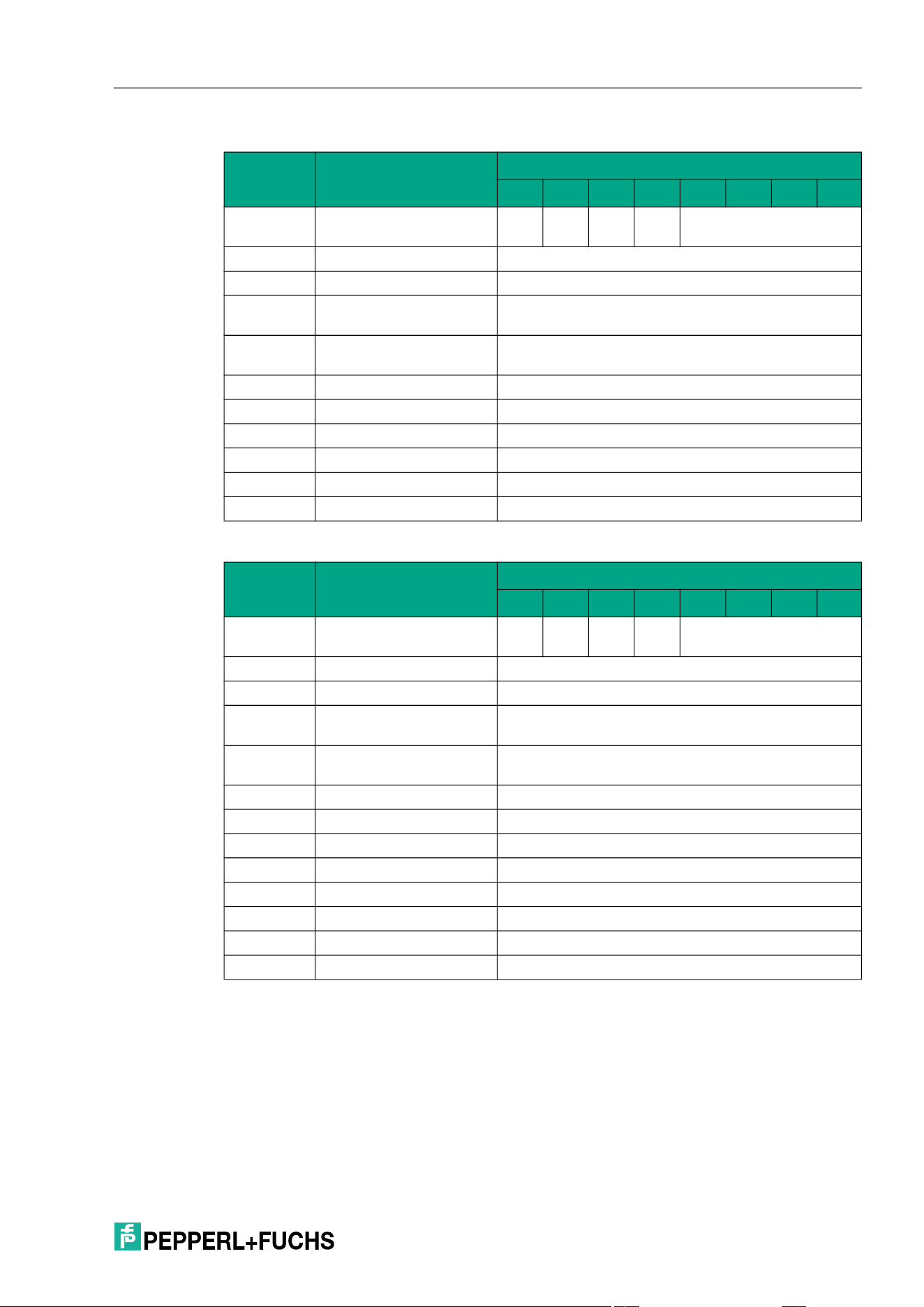
IQT3 / IQT4 Series
ExpertMode
2026-05
89
Response telegram 2 – status 16#0B (information frame mode
Response telegram 3 – status 16#0F (long-form data format)
Selective Enhanced Read Fixcode (XEF)
The XEF command has the command code 16#E9. In principle, the command functions in
exactly the same way as the EF command (16#1D), but is only executed for a selected tag.
The parameters <UID Mask Byte 1> to <UID Mask Byte 8> are used to specify the UID of the
selected tag. <Length UID Mask in Bit> specifies the length of the UID in bits.
Byte Content
Bit number
7 6 5 4 3 2 1 0
Byte 0 Control byte / frame
length
D
S
U
M
U
D
0 16#0
Byte 1 Frame length 16#09
Byte 2 Fragmentation counter 16#00
Byte 3 Telegram length (high
byte)
16#00
Byte 4 Telegram length (low
byte)
16#06
Byte 5 Command 16#E8
Byte 6 Status 16#0B
Byte 7 Data 16#01 <Info Type>
Byte 8 Data <RSSI>
… Data 16#00
Byte 31 Data 16#00
Byte Content
Bit number
7 6 5 4 3 2 1 0
Byte 0 Control byte / frame
length
D
S
U
M
U
D
0 16#0
Byte 1 Frame length 16#0B
Byte 2 Fragmentation counter 16#00
Byte 3 Telegram length (high
byte)
16#00
Byte 4 Telegram length (low
byte)
16#08
Byte 5 Command 16#E8
Byte 6 Status 16#0F
Byte 7 Data <Number of Tags Byte 1>
Byte 8 Data <Number of Tags Byte 2>
Byte 9 Data <Number of Tags Byte 3>
Byte 10 Data <Number of Tags Byte 4>
… Data 16#00
Byte 31 Data 16#00
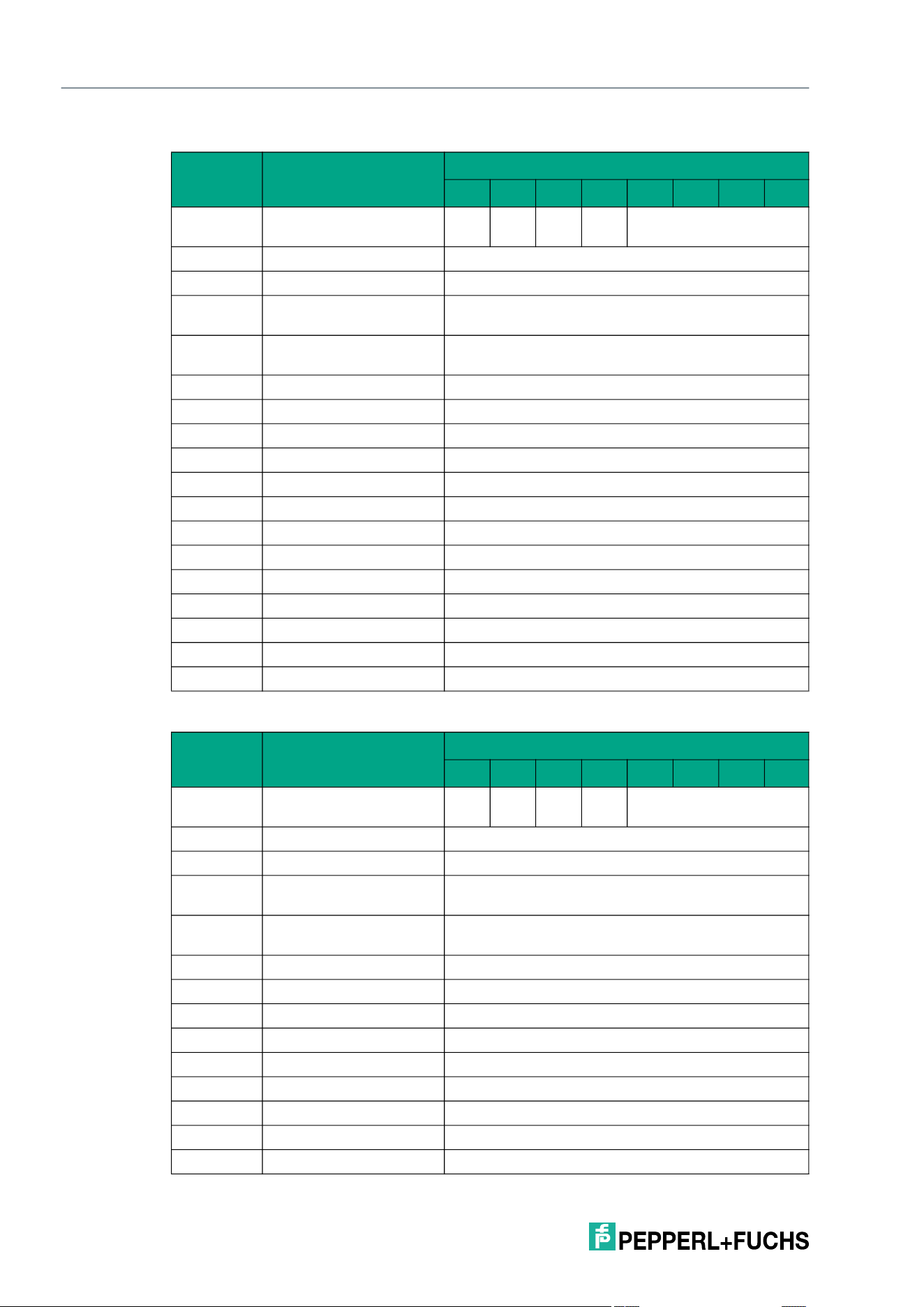
2026-05
90
IQT3 / IQT4 Series
ExpertMode
Command telegram (8 byte UID mask)
Response telegram 1 – status 16#00 (long-form data format)
Byte Content
Bit number
7 6 5 4 3 2 1 0
Byte 0 Control byte / frame
length
D
S
U
M
U
D
0 16#0
Byte 1 Frame length 16#10
Byte 2 Fragmentation counter 16#00
Byte 3 Telegram length (high
byte)
16#00
Byte 4 Telegram length (low
byte)
16#0D
Byte 5 Command 16#E9
Byte 6 Command parameter 16#00 <Length UID Mask in Bit (High Byte)>
Byte 7 Command parameter 16#40 <Length UID Mask in Bit (Low Byte)>
Byte 8 Command parameter <UID Mask Byte 1>
Byte 9 Command parameter <UID Mask Byte 2>
Byte 10 Command parameter <UID Mask Byte 3>
Byte 11 Command parameter <UID Mask Byte 4>
Byte 12 Command parameter <UID Mask Byte 5>
Byte 13 Command parameter <UID Mask Byte 6>
Byte 14 Command parameter <UID Mask Byte 7>
Byte 15 Command parameter <UID Mask Byte 8>
… Command parameters 16#00
Byte 31 Command parameter 16#00
Byte Content
Bit number
7 6 5 4 3 2 1 0
Byte 0 Control byte / frame
length
D
S
U
M
U
D
0 16#0
Byte 1 Frame length 16#11
Byte 2 Fragmentation counter 16#00
Byte 3 Telegram length (high
byte)
16#00
Byte 4 Telegram length (low
byte)
16#0E
Byte 5 Command 16#E9
Byte 6 Status 16#00
Byte 7 Data 16#00 <Length UID in Bytes (High Byte)>
Byte 8 Data 16#08 <Length UID in Bytes (Low Byte)>
Byte 9 Data <UID Byte 1>
Byte 10 Data <UID Byte 2>
Byte 11 Data <UID Byte 3>
Byte 12 Data <UID Byte 4>
Byte 13 Data <UID Byte 5>
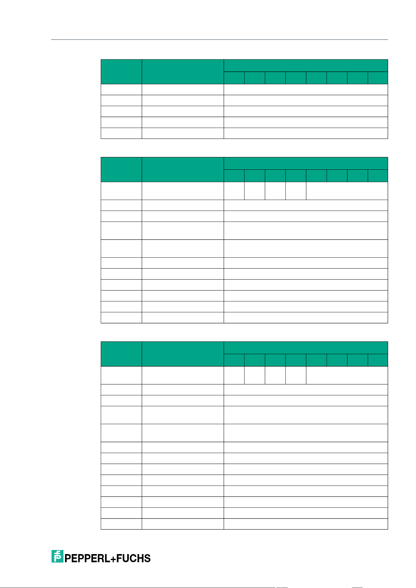
IQT3 / IQT4 Series
ExpertMode
2026-05
91
Response telegram 2 – status 16#0B (information frame mode
Response telegram 3 – status 16#05 (long-form data format)
Byte 14 Data <UID Byte 6>
Byte 15 Data <UID Byte 7>
Byte 16 Data <UID Byte 8>
… Data 16#00
Byte 31 Data 16#00
Byte Content
Bit number
7 6 5 4 3 2 1 0
Byte 0 Control byte / frame
length
D
S
U
M
U
D
0 16#0
Byte 1 Frame length 16#09
Byte 2 Fragmentation counter 16#00
Byte 3 Telegram length (high
byte)
16#00
Byte 4 Telegram length (low
byte)
16#06
Byte 5 Command 16#E9
Byte 6 Status 16#0B
Byte 7 Data 16#01 <Info Type>
Byte 8 Data <RSSI>
… Data 16#00
Byte 31 Data 16#00
Byte Content
Bit number
7 6 5 4 3 2 1 0
Byte 0 Control byte / frame
length
D
S
U
M
U
D
0 16#0
Byte 1 Frame length 16#11
Byte 2 Fragmentation counter 16#00
Byte 3 Telegram length (high
byte)
16#00
Byte 4 Telegram length (low
byte)
16#0E
Byte 5 Command 16#E9
Byte 6 Status 16#05
Byte 7 Data 16#00 <Length UID in Bytes (High Byte)>
Byte 8 Data 16#08 <Length UID in Bytes (Low Byte)>
Byte 9 Data <UID Byte 1>
Byte 10 Data <UID Byte 2>
Byte 11 Data <UID Byte 3>
Byte 12 Data <UID Byte 4>
Byte Content
Bit number
7 6 5 4 3 2 1 0
2026-05
92
IQT3 / IQT4 Series
ExpertMode
Selective Single Read 4-Byte Blocks (XSR)
The XSR command has the command code 16#E0. In principle, the command functions in
exactly the same way as the SR command (16#10), but is only executed for a selected tag.
The parameters <UID Mask Byte 1> to <UID Mask Byte 8> are used to specify the UID of the
selected tag. <Length UID Mask in Bit> specifies the length of the UID in bits.
Command telegram (8 byte UID mask, 4 byte user data)
Byte 13 Data <UID Byte 5>
Byte 14 Data <UID Byte 6>
Byte 15 Data <UID Byte 7>
Byte 16 Data <UID Byte 8>
… Data 16#00
Byte 31 Data 16#00
Byte Content
Bit number
7 6 5 4 3 2 1 0
Byte 0 Control byte / frame
length
D
S
U
M
U
D
0 16#0
Byte 1 Frame length 16#14
Byte 2 Fragmentation counter 16#00
Byte 3 Telegram length (high
byte)
16#00
Byte 4 Telegram length (low
byte)
16#11
Byte 5 Command 16#E0
Byte 6 Command parameter 16#00 <Length UID Mask in Bit (High Byte)>
Byte 7 Command parameter 16#40 <Length UID Mask in Bit (Low Byte)>
Byte 8 Command parameter <UID Mask Byte 1>
Byte 9 Command parameter <UID Mask Byte 2>
Byte 10 Command parameter <UID Mask Byte 3>
Byte 11 Command parameter <UID Mask Byte 4>
Byte 12 Command parameter <UID Mask Byte 5>
Byte 13 Command parameter <UID Mask Byte 6>
Byte 14 Command parameter <UID Mask Byte 7>
Byte 15 Command parameter <UID Mask Byte 8>
Byte 16 Command parameter <Start Address (High Byte)>
Byte 17 Command parameter <Start Address (Low Byte)>
Byte 18 Command parameter <Number of Bytes (High Byte)>
Byte 19 Command parameter <Number of Bytes (Low Byte)>
… Command parameters 16#00
Byte 31 Command parameter 16#00
Byte Content
Bit number
7 6 5 4 3 2 1 0
IQT3 / IQT4 Series
ExpertMode
2026-05
93
Response telegram 1 – status 16#00 (long-form data format)
Response telegram 2 – status 16#0B (information frame mode
Byte Content
Bit number
7 6 5 4 3 2 1 0
Byte 0 Control byte / frame
length
D
S
U
M
U
D
0 16#0
Byte 1 Frame length 16#17
Byte 2 Fragmentation counter 16#00
Byte 3 Telegram length (high
byte)
16#00
Byte 4 Telegram length (low
byte)
16#14
Byte 5 Command 16#E0
Byte 6 Status 16#00
Byte 7 Data 16#00 <Length UID in Bytes (High Byte)>
Byte 8 Data 16#08 <Length UID in Bytes (Low Byte)>
Byte 9 Data <UID Byte 1>
Byte 10 Data <UID Byte 2>
Byte 11 Data <UID Byte 3>
Byte 12 Data <UID Byte 4>
Byte 13 Data <UID Byte 5>
Byte 14 Data <UID Byte 6>
Byte 15 Data <UID Byte 7>
Byte 16 Data <UID Byte 8>
Byte 17 Data 16#00
Byte 18 Data 16#04
Byte 19 Data <User Data Byte 1>
Byte 20 Data <User Data Byte 2>
Byte 21 Data <User Data Byte 3>
Byte 22 Data <User Data Byte 4>
… Data 16#00
Byte 31 Data 16#00
Byte Content
Bit number
7 6 5 4 3 2 1 0
Byte 0 Control byte / frame
length
D
S
U
M
U
D
0 16#0
Byte 1 Frame length 16#09
Byte 2 Fragmentation counter 16#00
Byte 3 Telegram length (high
byte)
16#00
Byte 4 Telegram length (low
byte)
16#06
Byte 5 Command 16#E0
Byte 6 Status 16#0B
2026-05
94
IQT3 / IQT4 Series
ExpertMode
Response telegram 3 – status 16#0F (long-form data format)
Selective Enhanced Read 4-Byte Blocks (XER)
The XER command has the command code 16#D9. In principle, the command functions in
exactly the same way as the ER command (16#19), but is only executed for a selected tag.
The parameters <UID Mask Byte 1> to <UID Mask Byte 8> are used to specify the UID of the
selected tag. <Length UID Mask in Bit> specifies the length of the UID in bits.
Command telegram (8 byte UID mask, 4 byte user data)
Byte 7 Data 16#01 <Info Type>
Byte 8 Data <RSSI>
… Data 16#00
Byte 31 Data 16#00
Byte Content
Bit number
7 6 5 4 3 2 1 0
Byte 0 Control byte / frame
length
D
S
U
M
U
D
0 16#0
Byte 1 Frame length 16#0B
Byte 2 Fragmentation counter 16#00
Byte 3 Telegram length (high
byte)
16#00
Byte 4 Telegram length (low
byte)
16#08
Byte 5 Command 16#E0
Byte 6 Status 16#0F
Byte 7 Data <Number of Tags Byte 1>
Byte 8 Data <Number of Tags Byte 2>
Byte 9 Data <Number of Tags Byte 3>
Byte 10 Data <Number of Tags Byte 4>
… Data 16#00
Byte 31 Data 16#00
Byte Content
Bit number
7 6 5 4 3 2 1 0
Byte 0 Control byte / frame
length
D
S
U
M
U
D
0 16#0
Byte 1 Frame length 16#14
Byte 2 Fragmentation counter 16#00
Byte 3 Telegram length (high
byte)
16#00
Byte 4 Telegram length (low
byte)
16#11
Byte 5 Command 16#D9
Byte 6 Command parameter 16#00 <Length UID Mask in Bit (High Byte)>
Byte Content
Bit number
7 6 5 4 3 2 1 0
IQT3 / IQT4 Series
ExpertMode
2026-05
95
Response telegram 1 – status 16#00 (long-form data format)
Byte 7 Command parameter 16#40 <Length UID Mask in Bit (Low Byte)>
Byte 8 Command parameter <UID Mask Byte 1>
Byte 9 Command parameter <UID Mask Byte 2>
Byte 10 Command parameter <UID Mask Byte 3>
Byte 11 Command parameter <UID Mask Byte 4>
Byte 12 Command parameter <UID Mask Byte 5>
Byte 13 Command parameter <UID Mask Byte 6>
Byte 14 Command parameter <UID Mask Byte 7>
Byte 15 Command parameter <UID Mask Byte 8>
Byte 16 Command parameter <Start Address (High Byte)>
Byte 17 Command parameter <Start Address (Low Byte)>
Byte 18 Command parameter <Number of Bytes (High Byte)>
Byte 19 Command parameter <Number of Bytes (Low Byte)>
… Command parameters 16#00
Byte 31 Command parameter 16#00
Byte Content
Bit number
7 6 5 4 3 2 1 0
Byte 0 Control byte / frame
length
D
S
U
M
U
D
0 16#0
Byte 1 Frame length 16#17
Byte 2 Fragmentation counter 16#00
Byte 3 Telegram length (high
byte)
16#00
Byte 4 Telegram length (low
byte)
16#14
Byte 5 Command 16#D9
Byte 6 Status 16#00
Byte 7 Data 16#00 <Length UID in Bytes (High Byte)>
Byte 8 Data 16#08 <Length UID in Bytes (Low Byte)>
Byte 9 Data <UID Byte 1>
Byte 10 Data <UID Byte 2>
Byte 11 Data <UID Byte 3>
Byte 12 Data <UID Byte 4>
Byte 13 Data <UID Byte 5>
Byte 14 Data <UID Byte 6>
Byte 15 Data <UID Byte 7>
Byte 16 Data <UID Byte 8>
Byte 17 Data 16#00
Byte 18 Data 16#04
Byte 19 Data <User Data Byte 1>
Byte Content
Bit number
7 6 5 4 3 2 1 0
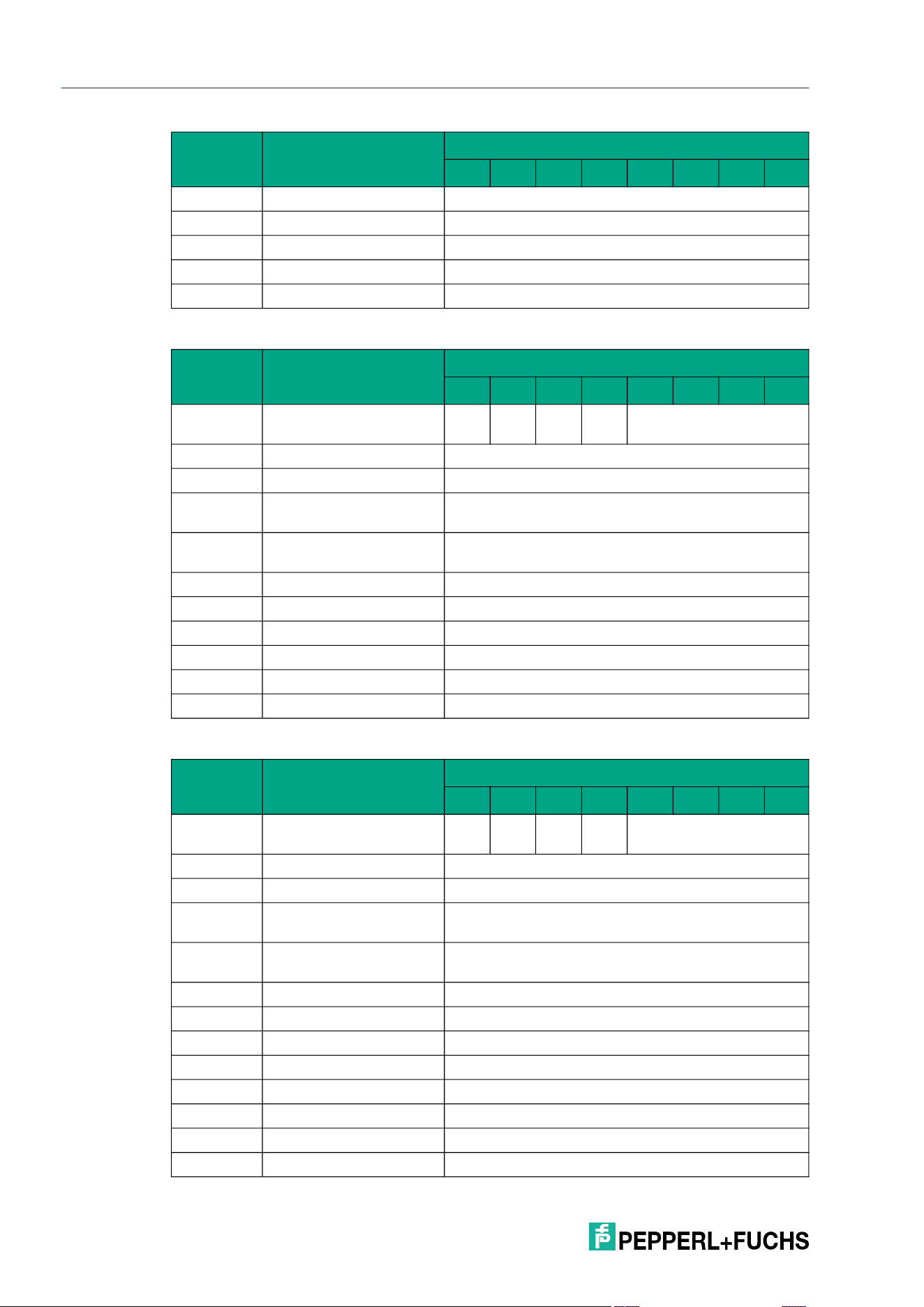
2026-05
96
IQT3 / IQT4 Series
ExpertMode
Response telegram 2 – status 16#0B (information frame mode
Response telegram 3 – status 16#05 (long-form data format)
Byte 20 Data <User Data Byte 2>
Byte 21 Data <User Data Byte 3>
Byte 22 Data <User Data Byte 4>
… Data 16#00
Byte 31 Data 16#00
Byte Content
Bit number
7 6 5 4 3 2 1 0
Byte 0 Control byte / frame
length
D
S
U
M
U
D
0 16#0
Byte 1 Frame length 16#09
Byte 2 Fragmentation counter 16#00
Byte 3 Telegram length (high
byte)
16#00
Byte 4 Telegram length (low
byte)
16#06
Byte 5 Command 16#D9
Byte 6 Status 16#0B
Byte 7 Data 16#01 <Info Type>
Byte 8 Data <RSSI>
… Data 16#00
Byte 31 Data 16#00
Byte Content
Bit number
7 6 5 4 3 2 1 0
Byte 0 Control byte / frame
length
D
S
U
M
U
D
0 16#0
Byte 1 Frame length 16#11
Byte 2 Fragmentation counter 16#00
Byte 3 Telegram length (high
byte)
16#00
Byte 4 Telegram length (low
byte)
16#0E
Byte 5 Command 16#D9
Byte 6 Status 16#05
Byte 7 Data 16#00 <Length UID in Bytes (High Byte)>
Byte 8 Data 16#08 <Length UID in Bytes (Low Byte)>
Byte 9 Data <UID Byte 1>
Byte 10 Data <UID Byte 2>
Byte 11 Data <UID Byte 3>
Byte 12 Data <UID Byte 4>
Byte Content
Bit number
7 6 5 4 3 2 1 0
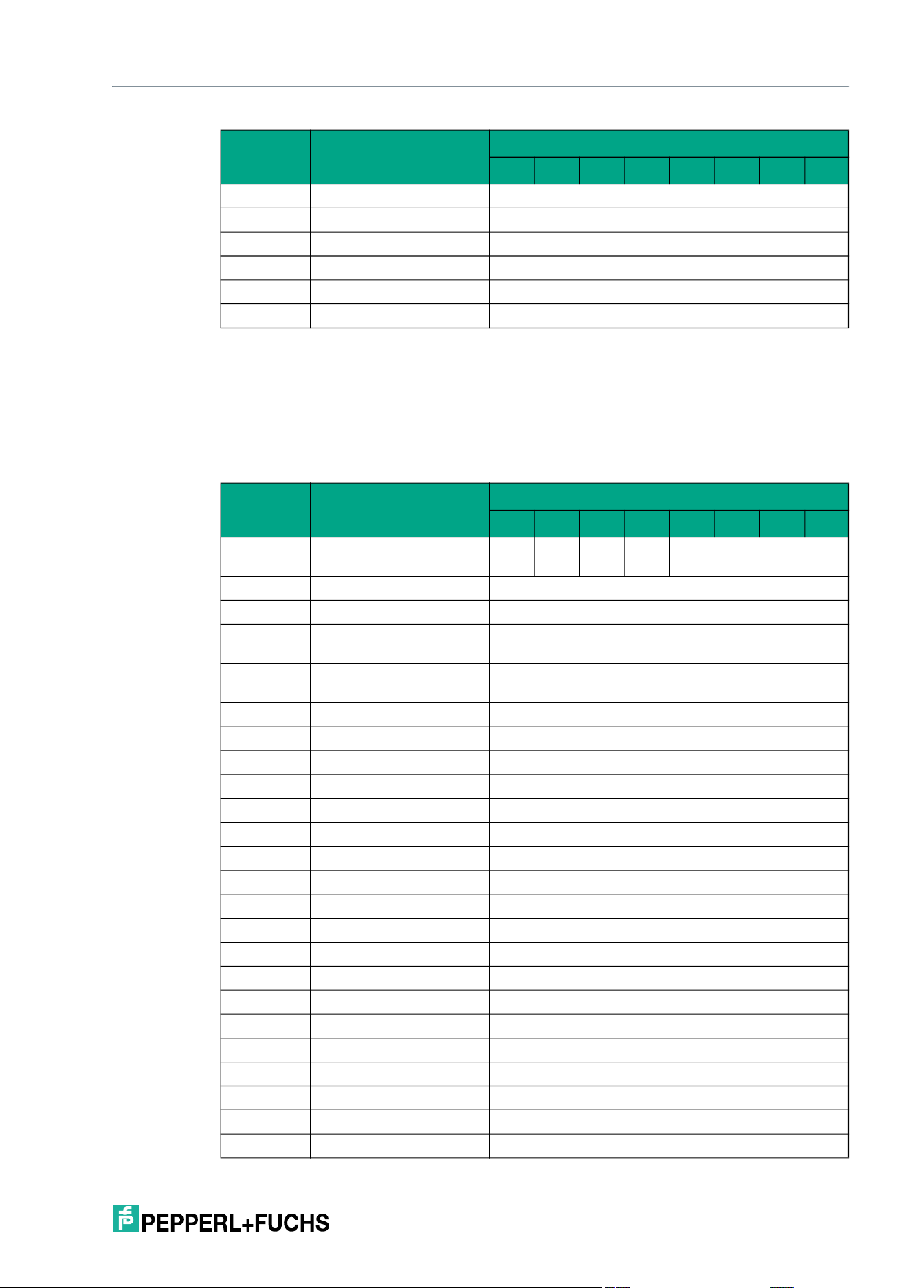
IQT3 / IQT4 Series
ExpertMode
2026-05
97
Selective Single Write 4-Byte Blocks (XSW)
The XSW command has the command code 16#E3. In principle, the command functions in
exactly the same way as the SW command (16#40), but is only executed for a selected tag.
The parameters <UID Mask Byte 1> to <UID Mask Byte 8> are used to specify the UID of the
selected tag. <Length UID Mask in Bit> specifies the length of the UID in bits.
Command telegram (8 byte UID mask, 4 byte user data)
Byte 13 Data <UID Byte 5>
Byte 14 Data <UID Byte 6>
Byte 15 Data <UID Byte 7>
Byte 16 Data <UID Byte 8>
… Data 16#00
Byte 31 Data 16#00
Byte Content
Bit number
7 6 5 4 3 2 1 0
Byte 0 Control byte / frame
length
D
S
U
M
U
D
0 16#0
Byte 1 Frame length 16#18
Byte 2 Fragmentation counter 16#00
Byte 3 Telegram length (high
byte)
16#00
Byte 4 Telegram length (low
byte)
16#15
Byte 5 Command 16#E3
Byte 6 Command parameter 16#00 <Length UID Mask in Bit (High Byte)>
Byte 7 Command parameter 16#40 <Length UID Mask in Bit (Low Byte)>
Byte 8 Command parameter <UID Mask Byte 1>
Byte 9 Command parameter <UID Mask Byte 2>
Byte 10 Command parameter <UID Mask Byte 3>
Byte 11 Command parameter <UID Mask Byte 4>
Byte 12 Command parameter <UID Mask Byte 5>
Byte 13 Command parameter <UID Mask Byte 6>
Byte 14 Command parameter <UID Mask Byte 7>
Byte 15 Command parameter <UID Mask Byte 8>
Byte 16 Command parameter 16#00 <Start Address (High Byte)>
Byte 17 Command parameter 16#00 <Start Address (Low Byte)>
Byte 18 Command parameter 16#00 <Number of Bytes (High Byte)>
Byte 19 Command parameter 16#04 <Number of Bytes (Low Byte)>
Byte 20 Command parameter <Data Byte 1>
Byte 21 Command parameter <Data Byte 2>
Byte 22 Command parameter <Data Byte 3>
Byte 23 Command parameter <Data Byte 4>
Byte Content
Bit number
7 6 5 4 3 2 1 0
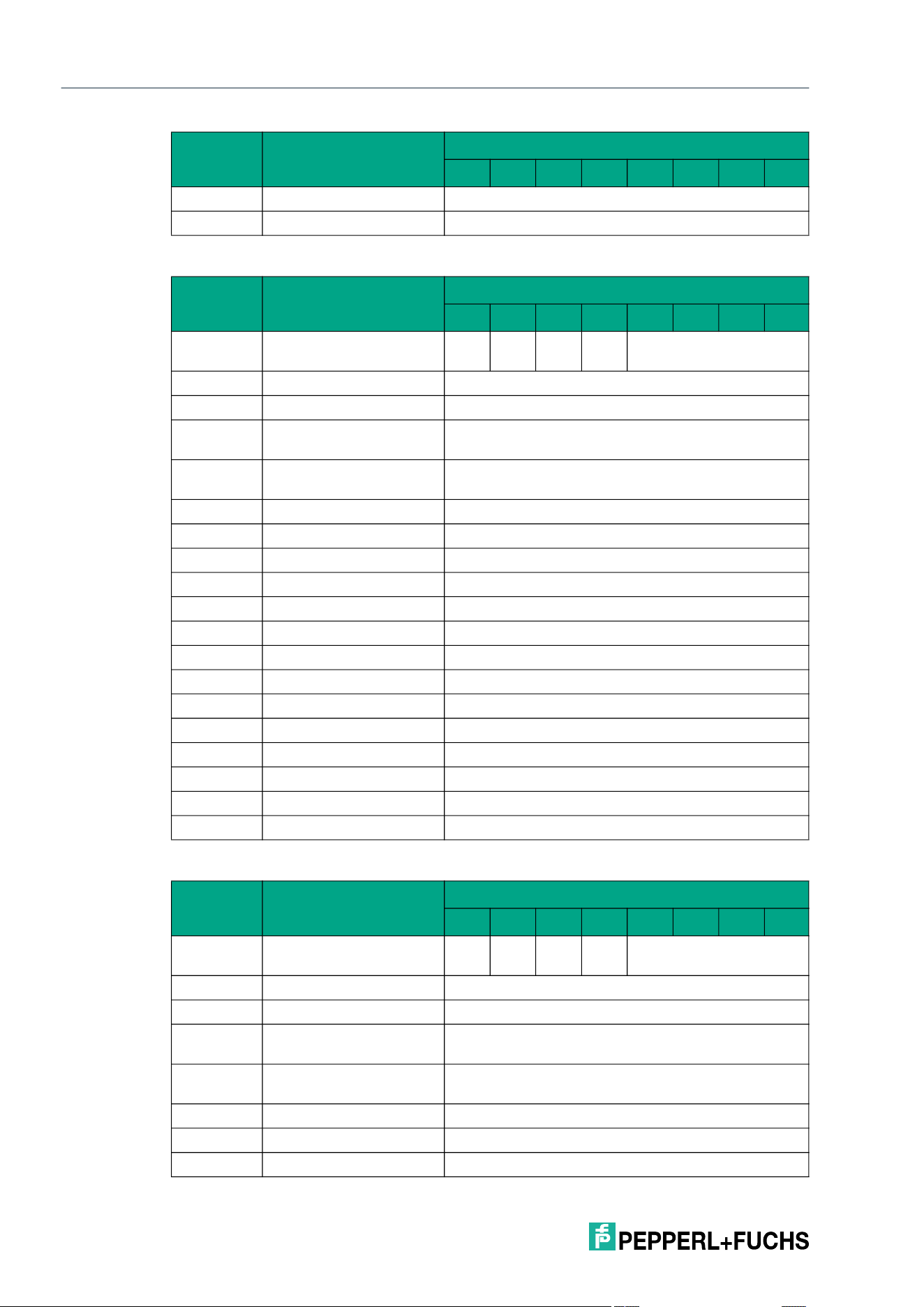
2026-05
98
IQT3 / IQT4 Series
ExpertMode
Response telegram 1 – status 16#00 (long-form data format)
Response telegram 2 – status 16#0B (information frame mode
… Command parameters 16#00
Byte 31 Command parameter 16#00
Byte Content
Bit number
7 6 5 4 3 2 1 0
Byte 0 Control byte / frame
length
D
S
U
M
U
D
0 16#0
Byte 1 Frame length 16#11
Byte 2 Fragmentation counter 16#00
Byte 3 Telegram length (high
byte)
16#00
Byte 4 Telegram length (low
byte)
16#0E
Byte 5 Command 16#E3
Byte 6 Status 16#00
Byte 7 Data 16#00 <Length UID in Bytes (High Byte)>
Byte 8 Data 16#08 <Length UID in Bytes (Low Byte)>
Byte 9 Data <UID Byte 1>
Byte 10 Data <UID Byte 2>
Byte 11 Data <UID Byte 3>
Byte 12 Data <UID Byte 4>
Byte 13 Data <UID Byte 5>
Byte 14 Data <UID Byte 6>
Byte 15 Data <UID Byte 7>
Byte 16 Data <UID Byte 8>
… Data 16#00
Byte 31 Data 16#00
Byte Content
Bit number
7 6 5 4 3 2 1 0
Byte 0 Control byte / frame
length
D
S
U
M
U
D
0 16#0
Byte 1 Frame length 16#09
Byte 2 Fragmentation counter 16#00
Byte 3 Telegram length (high
byte)
16#00
Byte 4 Telegram length (low
byte)
16#06
Byte 5 Command 16#E3
Byte 6 Status 16#0B
Byte 7 Data 16#01 <Info Type>
Byte Content
Bit number
7 6 5 4 3 2 1 0
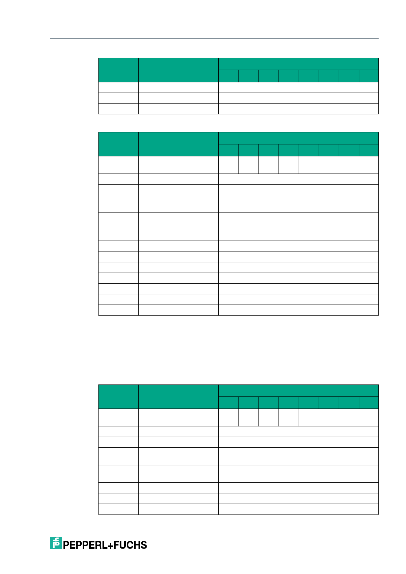
IQT3 / IQT4 Series
ExpertMode
2026-05
99
Response telegram 3 – status 16#0F (long-form data format)
Selective Enhanced Write 4-Byte Blocks (XEW)
The XEW command has the command code 16#DC. In principle, the command functions in
exactly the same way as the EW command (16#1A), but is only executed for a selected tag.
The parameters <UID Mask Byte 1> to <UID Mask Byte 8> are used to specify the UID of the
selected tag. <Length UID Mask in Bit> specifies the length of the UID in bits.
Command telegram (8 byte UID mask, 4 byte user data)
Byte 8 Data <RSSI>
… Data 16#00
Byte 31 Data 16#00
Byte Content
Bit number
7 6 5 4 3 2 1 0
Byte 0 Control byte / frame
length
D
S
U
M
U
D
0 16#0
Byte 1 Frame length 16#0B
Byte 2 Fragmentation counter 16#00
Byte 3 Telegram length (high
byte)
16#00
Byte 4 Telegram length (low
byte)
16#08
Byte 5 Command 16#E3
Byte 6 Status 16#0F
Byte 7 Data <Number of Tags Byte 1>
Byte 8 Data <Number of Tags Byte 2>
Byte 9 Data <Number of Tags Byte 3>
Byte 10 Data <Number of Tags Byte 4>
… Data 16#00
Byte 31 Data 16#00
Byte Content
Bit number
7 6 5 4 3 2 1 0
Byte 0 Control byte / frame
length
D
S
U
M
U
D
0 16#0
Byte 1 Frame length 16#18
Byte 2 Fragmentation counter 16#00
Byte 3 Telegram length (high
byte)
16#00
Byte 4 Telegram length (low
byte)
16#15
Byte 5 Command 16#DC
Byte 6 Command parameter 16#00 <Length UID Mask in Bit (High Byte)>
Byte 7 Command parameter 16#40 <Length UID Mask in Bit (Low Byte)>
Byte Content
Bit number
7 6 5 4 3 2 1 0
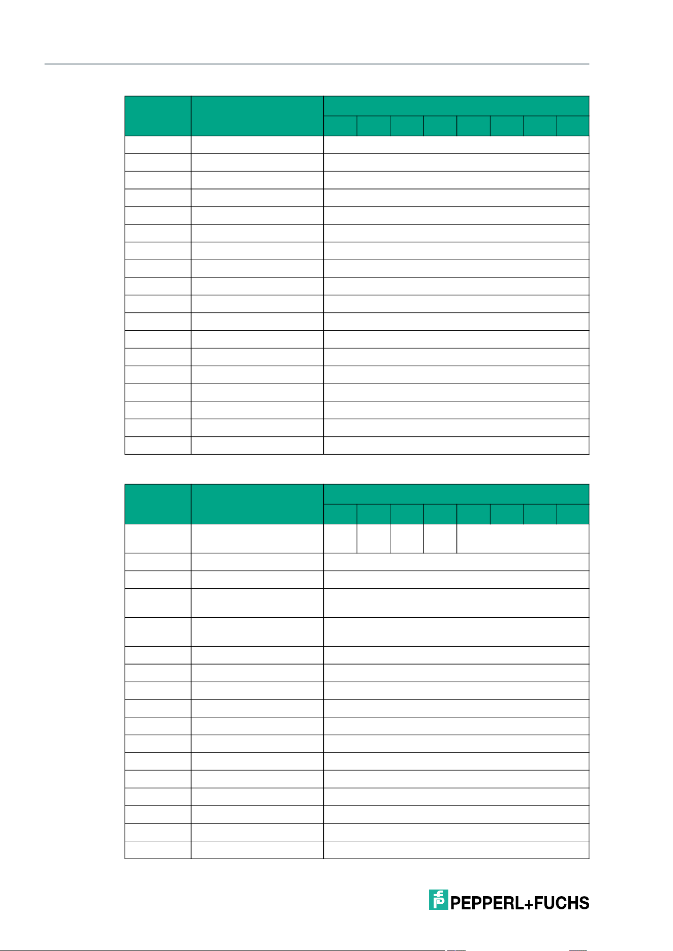
2026-05
100
IQT3 / IQT4 Series
ExpertMode
Response telegram 1 – status 16#00 (long-form data format)
Byte 8 Command parameter <UID Mask Byte 1>
Byte 9 Command parameter <UID Mask Byte 2>
Byte 10 Command parameter <UID Mask Byte 3>
Byte 11 Command parameter <UID Mask Byte 4>
Byte 12 Command parameter <UID Mask Byte 5>
Byte 13 Command parameter <UID Mask Byte 6>
Byte 14 Command parameter <UID Mask Byte 7>
Byte 15 Command parameter <UID Mask Byte 8>
Byte 16 Command parameter 16#00 <Start Address (High Byte)>
Byte 17 Command parameter 16#00 <Start Address (Low Byte)>
Byte 18 Command parameter 16#00 <Number of Bytes (High Byte)>
Byte 19 Command parameter 16#04 <Number of Bytes (Low Byte)>
Byte 20 Command parameter <Data Byte 1>
Byte 21 Command parameter <Data Byte 2>
Byte 22 Command parameter <Data Byte 3>
Byte 23 Command parameter <Data Byte 4>
… Command parameters 16#00
Byte 31 Command parameter 16#00
Byte Content
Bit number
7 6 5 4 3 2 1 0
Byte 0 Control byte / frame
length
D
S
U
M
U
D
0 16#0
Byte 1 Frame length 16#11
Byte 2 Fragmentation counter 16#00
Byte 3 Telegram length (high
byte)
16#00
Byte 4 Telegram length (low
byte)
16#0E
Byte 5 Command 16#DC
Byte 6 Status 16#00
Byte 7 Data 16#00 <Length UID in Bytes (High Byte)>
Byte 8 Data 16#08 <Length UID in Bytes (Low Byte)>
Byte 9 Data <UID Byte 1>
Byte 10 Data <UID Byte 2>
Byte 11 Data <UID Byte 3>
Byte 12 Data <UID Byte 4>
Byte 13 Data <UID Byte 5>
Byte 14 Data <UID Byte 6>
Byte 15 Data <UID Byte 7>
Byte 16 Data <UID Byte 8>
Byte Content
Bit number
7 6 5 4 3 2 1 0
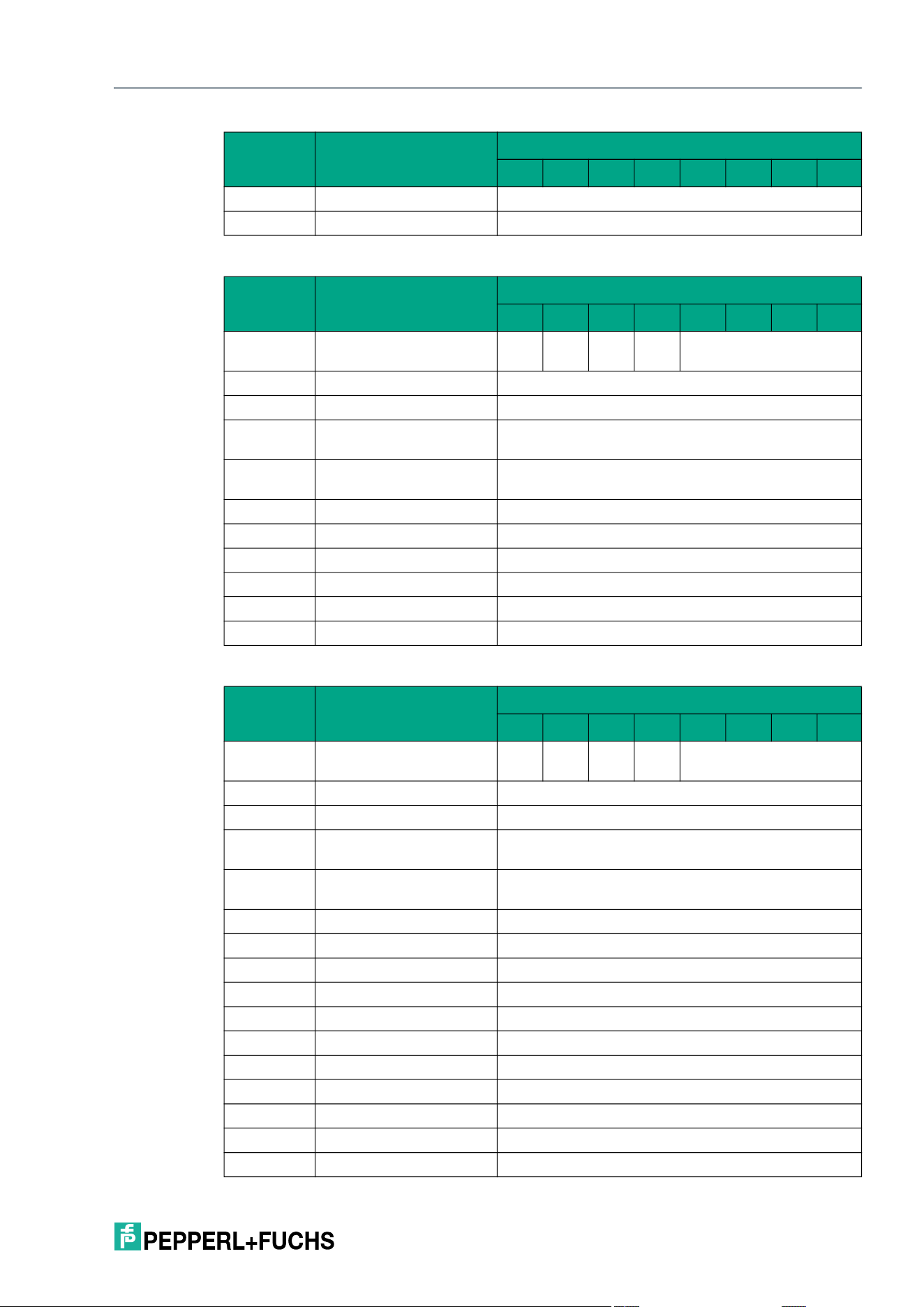
IQT3 / IQT4 Series
ExpertMode
2026-05
101
Response telegram 2 – status 16#0B (information frame mode
Response telegram 3 – status 16#05 (long-form data format)
… Data 16#00
Byte 31 Data 16#00
Byte Content
Bit number
7 6 5 4 3 2 1 0
Byte 0 Control byte / frame
length
D
S
U
M
U
D
0 16#0
Byte 1 Frame length 16#09
Byte 2 Fragmentation counter 16#00
Byte 3 Telegram length (high
byte)
16#00
Byte 4 Telegram length (low
byte)
16#06
Byte 5 Command 16#DC
Byte 6 Status 16#0B
Byte 7 Data 16#01 <Info Type>
Byte 8 Data <RSSI>
… Data 16#00
Byte 31 Data 16#00
Byte Content
Bit number
7 6 5 4 3 2 1 0
Byte 0 Control byte / frame
length
D
S
U
M
U
D
0 16#0
Byte 1 Frame length 16#11
Byte 2 Fragmentation counter 16#00
Byte 3 Telegram length (high
byte)
16#00
Byte 4 Telegram length (low
byte)
16#0E
Byte 5 Command 16#DC
Byte 6 Status 16#05
Byte 7 Data 16#00 <Length UID in Bytes (High Byte)>
Byte 8 Data 16#08 <Length UID in Bytes (Low Byte)>
Byte 9 Data <UID Byte 1>
Byte 10 Data <UID Byte 2>
Byte 11 Data <UID Byte 3>
Byte 12 Data <UID Byte 4>
Byte 13 Data <UID Byte 5>
Byte 14 Data <UID Byte 6>
Byte 15 Data <UID Byte 7>
Byte Content
Bit number
7 6 5 4 3 2 1 0
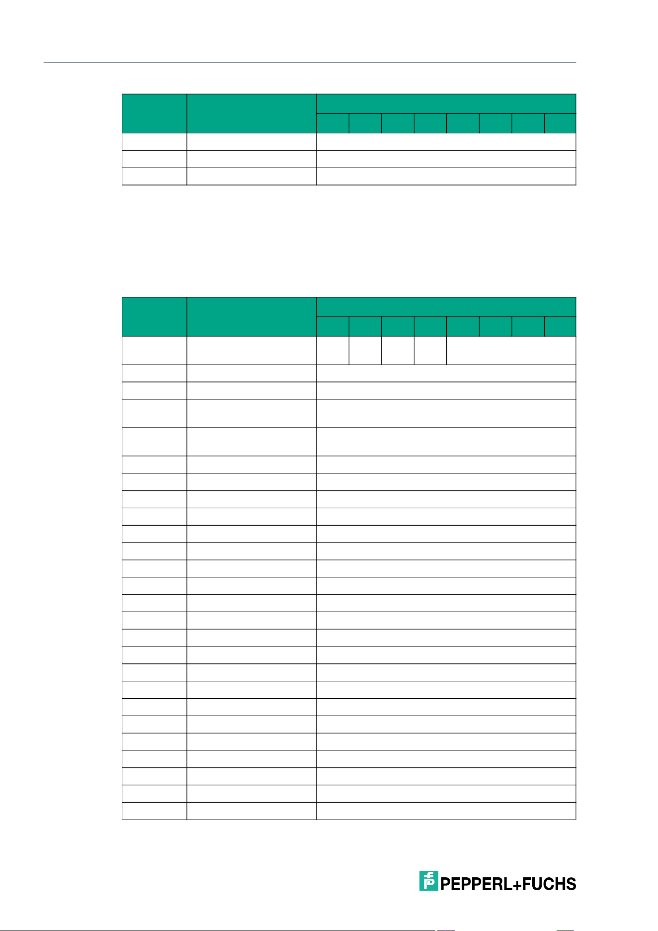
2026-05
102
IQT3 / IQT4 Series
ExpertMode
Selective Single Write 4-Byte Blocks with Lock (XSL)
The XSL command has the command code 16#E4. In principle, the command functions in
exactly the same way as the SL command (16#47), but is only executed for a selected tag.
The parameters <UID Mask Byte 1> to <UID Mask Byte 8> are used to specify the UID of the
selected tag. <Length UID Mask in Bit> specifies the length of the UID in bits.
Command telegram (8 byte UID mask, 4 byte user data)
Byte 16 Data <UID Byte 8>
… Data 16#00
Byte 31 Data 16#00
Byte Content
Bit number
7 6 5 4 3 2 1 0
Byte 0 Control byte / frame
length
D
S
U
M
U
D
0 16#0
Byte 1 Frame length 16#18
Byte 2 Fragmentation counter 16#00
Byte 3 Telegram length (high
byte)
16#00
Byte 4 Telegram length (low
byte)
16#15
Byte 5 Command 16#E4
Byte 6 Command parameter 16#00 <Length UID Mask in Bit (High Byte)>
Byte 7 Command parameter 16#40 <Length UID Mask in Bit (Low Byte)>
Byte 8 Command parameter <UID Mask Byte 1>
Byte 9 Command parameter <UID Mask Byte 2>
Byte 10 Command parameter <UID Mask Byte 3>
Byte 11 Command parameter <UID Mask Byte 4>
Byte 12 Command parameter <UID Mask Byte 5>
Byte 13 Command parameter <UID Mask Byte 6>
Byte 14 Command parameter <UID Mask Byte 7>
Byte 15 Command parameter <UID Mask Byte 8>
Byte 16 Command parameter 16#00 <Start Address (High Byte)>
Byte 17 Command parameter 16#00 <Start Address (Low Byte)>
Byte 18 Command parameter 16#00 <Number of Bytes (High Byte)>
Byte 19 Command parameter 16#04 <Number of Bytes (Low Byte)>
Byte 20 Command parameter <Data Byte 1>
Byte 21 Command parameter <Data Byte 2>
Byte 22 Command parameter <Data Byte 3>
Byte 23 Command parameter <Data Byte 4>
… Command parameters 16#00
Byte 31 Command parameter 16#00
Byte Content
Bit number
7 6 5 4 3 2 1 0
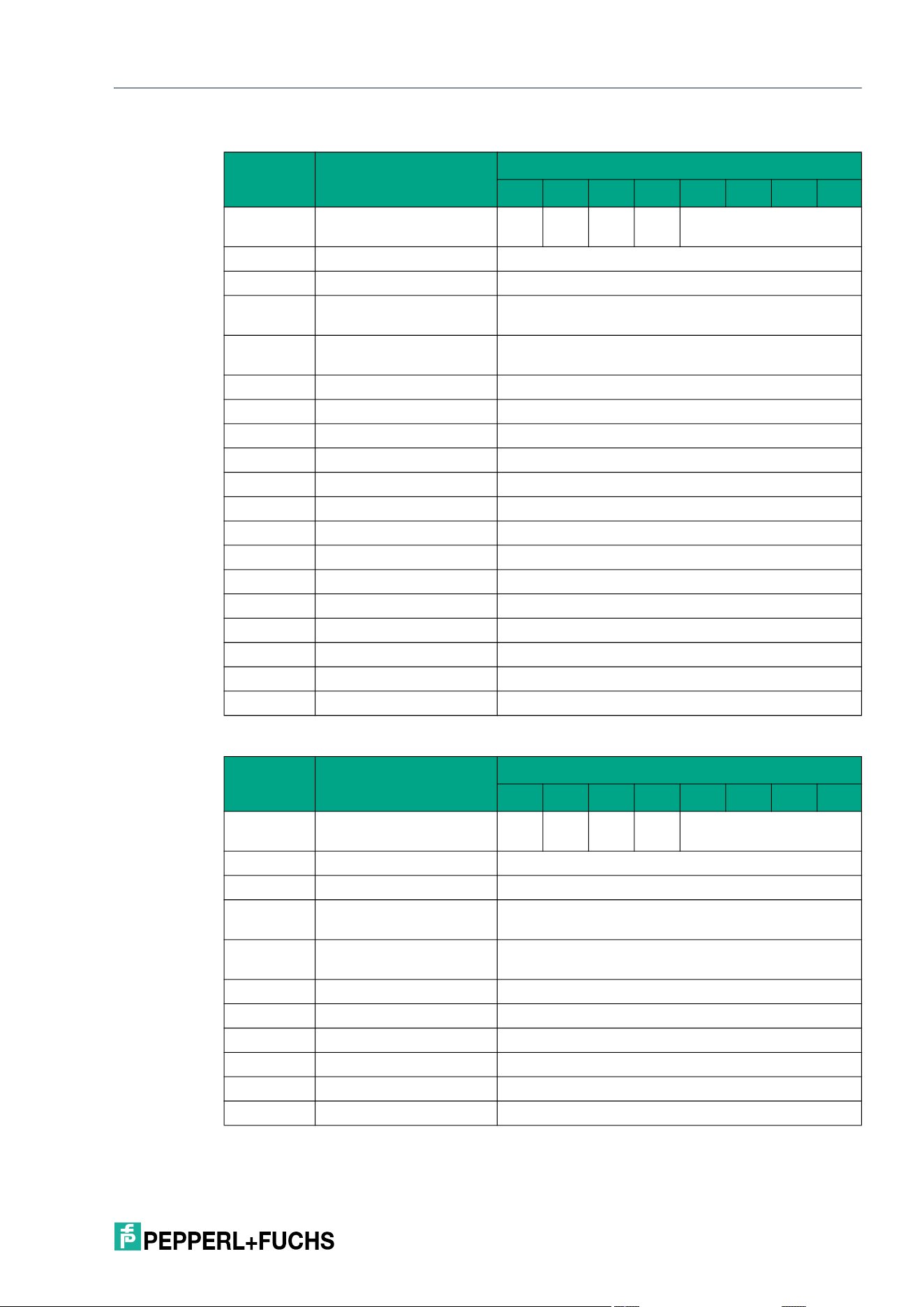
IQT3 / IQT4 Series
ExpertMode
2026-05
103
Response telegram 1 – status 16#00 (long-form data format)
Response telegram 2 – status 16#0B (information frame mode
Byte Content
Bit number
7 6 5 4 3 2 1 0
Byte 0 Control byte / frame
length
D
S
U
M
U
D
0 16#0
Byte 1 Frame length 16#11
Byte 2 Fragmentation counter 16#00
Byte 3 Telegram length (high
byte)
16#00
Byte 4 Telegram length (low
byte)
16#0E
Byte 5 Command 16#E4
Byte 6 Status 16#00
Byte 7 Data 16#00 <Length UID in Bytes (High Byte)>
Byte 8 Data 16#08 <Length UID in Bytes (Low Byte)>
Byte 9 Data <UID Byte 1>
Byte 10 Data <UID Byte 2>
Byte 11 Data <UID Byte 3>
Byte 12 Data <UID Byte 4>
Byte 13 Data <UID Byte 5>
Byte 14 Data <UID Byte 6>
Byte 15 Data <UID Byte 7>
Byte 16 Data <UID Byte 8>
… Data 16#00
Byte 31 Data 16#00
Byte Content
Bit number
7 6 5 4 3 2 1 0
Byte 0 Control byte / frame
length
D
S
U
M
U
D
0 16#0
Byte 1 Frame length 16#09
Byte 2 Fragmentation counter 16#00
Byte 3 Telegram length (high
byte)
16#00
Byte 4 Telegram length (low
byte)
16#06
Byte 5 Command 16#E4
Byte 6 Status 16#0B
Byte 7 Data 16#01 <Info Type>
Byte 8 Data <RSSI>
… Data 16#00
Byte 31 Data 16#00
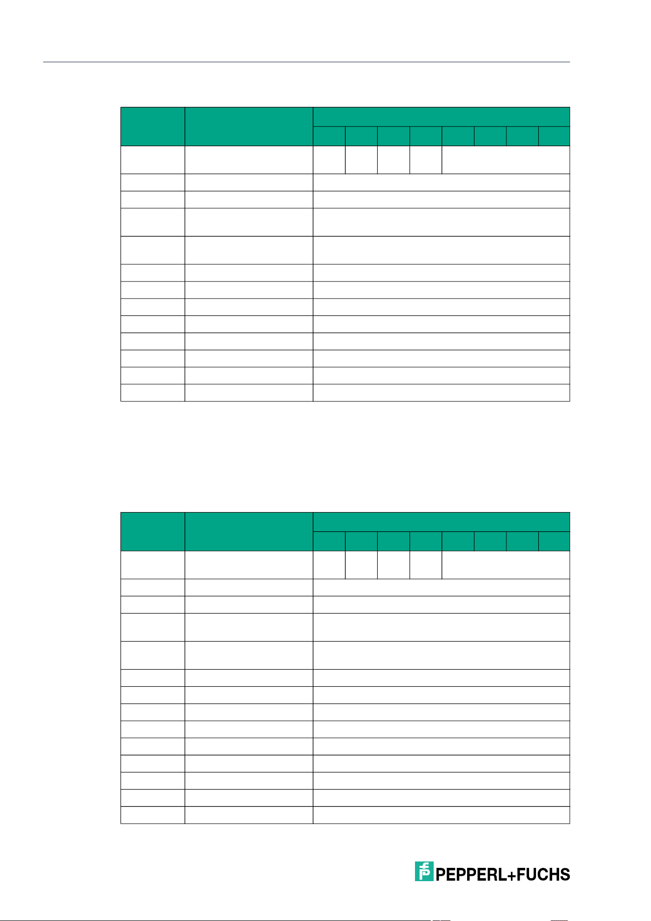
2026-05
104
IQT3 / IQT4 Series
ExpertMode
Response telegram 3 – status 16#0F (long-form data format)
Selective Enhanced Write 4-Byte Blocks with Lock (XEL)
The XEL command has the command code 16#E5. In principle, the command functions in
exactly the same way as the SL command (16#48), but is only executed for a selected tag.
The parameters <UID Mask Byte 1> to <UID Mask Byte 8> are used to specify the UID of the
selected tag. <Length UID Mask in Bit> specifies the length of the UID in bits.
Command telegram (8 byte UID mask, 4 byte user data)
Byte Content
Bit number
7 6 5 4 3 2 1 0
Byte 0 Control byte / frame
length
D
S
U
M
U
D
0 16#0
Byte 1 Frame length 16#0B
Byte 2 Fragmentation counter 16#00
Byte 3 Telegram length (high
byte)
16#00
Byte 4 Telegram length (low
byte)
16#08
Byte 5 Command 16#E4
Byte 6 Status 16#0F
Byte 7 Data <Number of Tags Byte 1>
Byte 8 Data <Number of Tags Byte 2>
Byte 9 Data <Number of Tags Byte 3>
Byte 10 Data <Number of Tags Byte 4>
… Data 16#00
Byte 31 Data 16#00
Byte Content
Bit number
7 6 5 4 3 2 1 0
Byte 0 Control byte / frame
length
D
S
U
M
U
D
0 16#0
Byte 1 Frame length 16#18
Byte 2 Fragmentation counter 16#00
Byte 3 Telegram length (high
byte)
16#00
Byte 4 Telegram length (low
byte)
16#15
Byte 5 Command 16#E5
Byte 6 Command parameter 16#00 <Length UID Mask in Bit (High Byte)>
Byte 7 Command parameter 16#40 <Length UID Mask in Bit (Low Byte)>
Byte 8 Command parameter <UID Mask Byte 1>
Byte 9 Command parameter <UID Mask Byte 2>
Byte 10 Command parameter <UID Mask Byte 3>
Byte 11 Command parameter <UID Mask Byte 4>
Byte 12 Command parameter <UID Mask Byte 5>
Byte 13 Command parameter <UID Mask Byte 6>
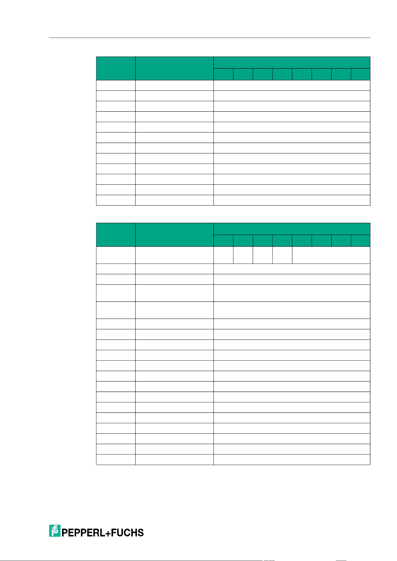
IQT3 / IQT4 Series
ExpertMode
2026-05
105
Response telegram 1 – status 16#00 (long-form data format):
Byte 14 Command parameter <UID Mask Byte 7>
Byte 15 Command parameter <UID Mask Byte 8>
Byte 16 Command parameter 16#00 <Start Address (High Byte)>
Byte 17 Command parameter 16#00 <Start Address (Low Byte)>
Byte 18 Command parameter 16#00 <Number of Bytes (High Byte)>
Byte 19 Command parameter 16#04 <Number of Bytes (Low Byte)>
Byte 20 Command parameter <Data Byte 1>
Byte 21 Command parameter <Data Byte 2>
Byte 22 Command parameter <Data Byte 3>
Byte 23 Command parameter <Data Byte 4>
… Command parameters 16#00
Byte 31 Command parameter 16#00
Byte Content
Bit number
7 6 5 4 3 2 1 0
Byte 0 Control byte / frame
length
D
S
U
M
U
D
0 16#0
Byte 1 Frame length 16#11
Byte 2 Fragmentation counter 16#00
Byte 3 Telegram length (high
byte)
16#00
Byte 4 Telegram length (low
byte)
16#0E
Byte 5 Command 16#E5
Byte 6 Status 16#00
Byte 7 Data 16#00 <Length UID in Bytes (High Byte)>
Byte 8 Data 16#08 <Length UID in Bytes (Low Byte)>
Byte 9 Data <UID Byte 1>
Byte 10 Data <UID Byte 2>
Byte 11 Data <UID Byte 3>
Byte 12 Data <UID Byte 4>
Byte 13 Data <UID Byte 5>
Byte 14 Data <UID Byte 6>
Byte 15 Data <UID Byte 7>
Byte 16 Data <UID Byte 8>
… Data 16#00
Byte 31 Data 16#00
Byte Content
Bit number
7 6 5 4 3 2 1 0
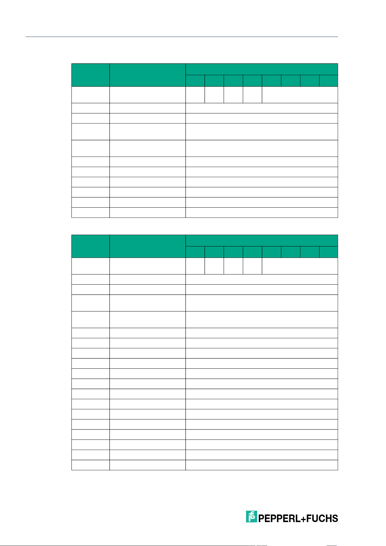
2026-05
106
IQT3 / IQT4 Series
ExpertMode
Response telegram 2 – status 16#0B (information frame mode
Response telegram 3 – status 16#05 (long-form data format)
Byte Content
Bit number
7 6 5 4 3 2 1 0
Byte 0 Control byte / frame
length
D
S
U
M
U
D
0 16#0
Byte 1 Frame length 16#09
Byte 2 Fragmentation counter 16#00
Byte 3 Telegram length (high
byte)
16#00
Byte 4 Telegram length (low
byte)
16#06
Byte 5 Command 16#E5
Byte 6 Status 16#0B
Byte 7 Data 16#01 <Info Type>
Byte 8 Data <RSSI>
… Data 16#00
Byte 31 Data 16#00
Byte Content
Bit number
7 6 5 4 3 2 1 0
Byte 0 Control byte / frame
length
D
S
U
M
U
D
0 16#0
Byte 1 Frame length 16#11
Byte 2 Fragmentation counter 16#00
Byte 3 Telegram length (high
byte)
16#00
Byte 4 Telegram length (low
byte)
16#0E
Byte 5 Command 16#E5
Byte 6 Status 16#05
Byte 7 Data 16#00 <Length UID in Bytes (High Byte)>
Byte 8 Data 16#08 <Length UID in Bytes (Low Byte)>
Byte 9 Data <UID Byte 1>
Byte 10 Data <UID Byte 2>
Byte 11 Data <UID Byte 3>
Byte 12 Data <UID Byte 4>
Byte 13 Data <UID Byte 5>
Byte 14 Data <UID Byte 6>
Byte 15 Data <UID Byte 7>
Byte 16 Data <UID Byte 8>
… Data 16#00
Byte 31 Data 16#00
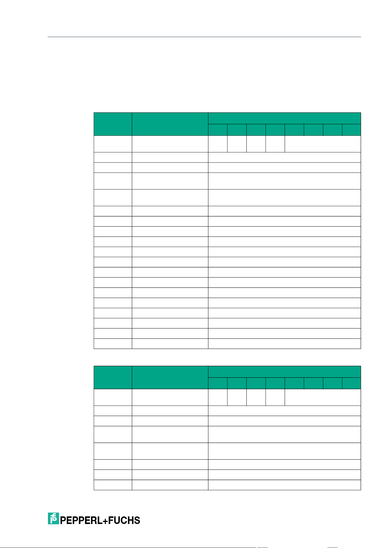
IQT3 / IQT4 Series
ExpertMode
2026-05
107
Selective Single Get Configuration (XSG)
The XSG command has the command code 16#DD. In principle, the command functions in
exactly the same way as the SG (16#61) command, but is only executed for a selected tag.
The parameters <UID Mask Byte 1> to <UID Mask Byte 8> are used to specify the UID of the
selected tag. <Length UID Mask in Bit> specifies the length of the UID in bits.
Command telegram (8 byte UID mask)
Response telegram 1 – status 16#00 (long-form data format)
Byte Content
Bit number
7 6 5 4 3 2 1 0
Byte 0 Control byte / frame
length
D
S
U
M
U
D
0 16#0
Byte 1 Frame length 16#11
Byte 2 Fragmentation counter 16#00
Byte 3 Telegram length (high
byte)
16#00
Byte 4 Telegram length (low
byte)
16#0E
Byte 5 Command 16#DD
Byte 6 Command parameter 16#00 <Length UID Mask in Bit (High Byte)>
Byte 7 Command parameter 16#40 <Length UID Mask in Bit (Low Byte)>
Byte 8 Command parameter <UID Mask Byte 1>
Byte 9 Command parameter <UID Mask Byte 2>
Byte 10 Command parameter <UID Mask Byte 3>
Byte 11 Command parameter <UID Mask Byte 4>
Byte 12 Command parameter <UID Mask Byte 5>
Byte 13 Command parameter <UID Mask Byte 6>
Byte 14 Command parameter <UID Mask Byte 7>
Byte 15 Command parameter <UID Mask Byte 8>
Byte 16 Command parameter 16#00 <Config Address>
… Command parameters 16#00
Byte 31 Command parameter 16#00
Byte Content
Bit number
7 6 5 4 3 2 1 0
Byte 0 Control byte / frame
length
D
S
U
M
U
D
0 16#0
Byte 1 Frame length 16#20
Byte 2 Fragmentation counter 16#01
Byte 3 Telegram length (high
byte)
16#00
Byte 4 Telegram length (low
byte)
16#1E
Byte 5 Command 16#DD
Byte 6 Status 16#00
Byte 7 Data 16#00 <Length UID in Bytes (High Byte)>
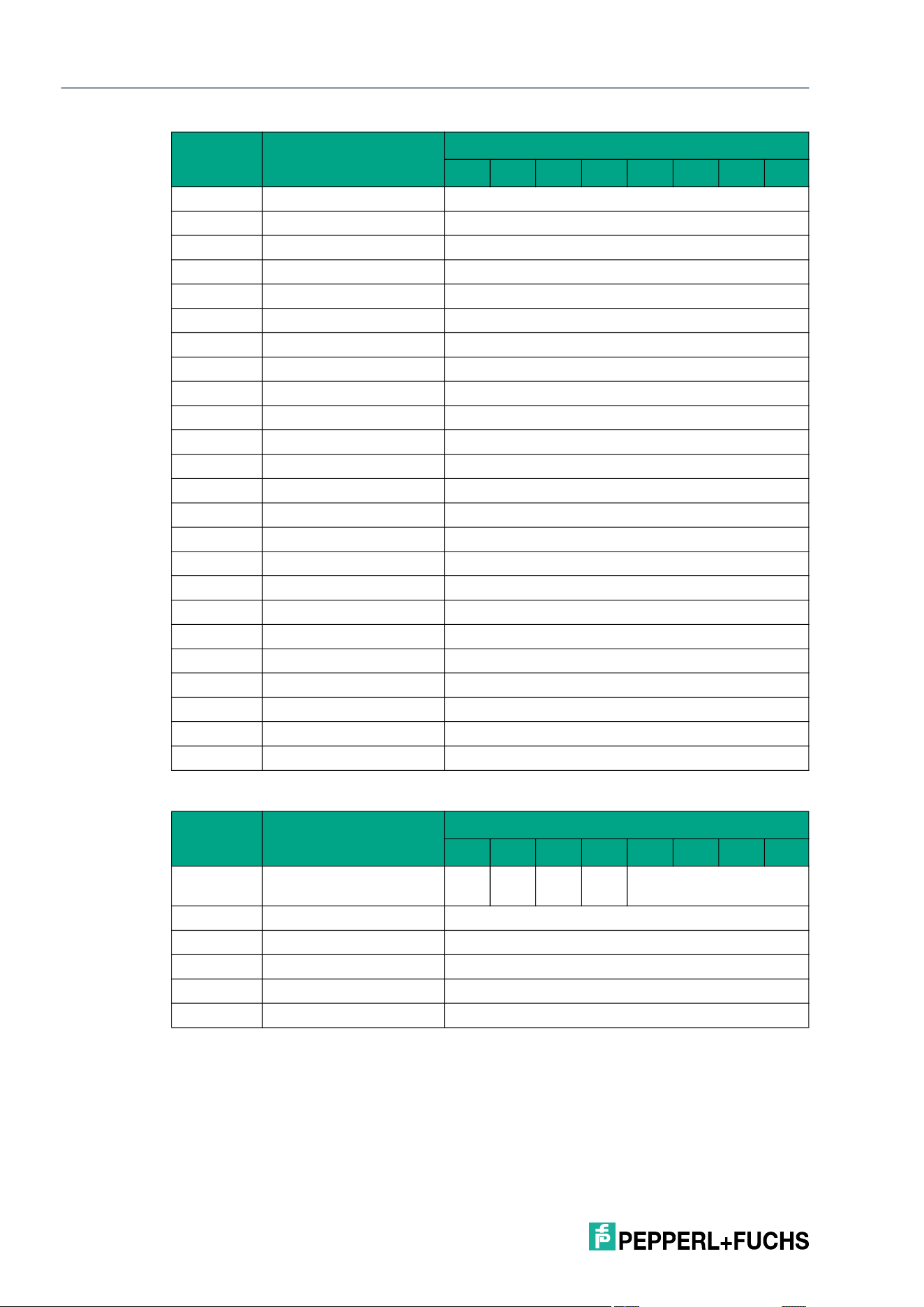
2026-05
108
IQT3 / IQT4 Series
ExpertMode
Response telegram 2 – status 16#00 (long-form data format)
Byte 8 Data 16#08 <Length UID in Bytes (Low Byte)>
Byte 9 Data <UID Byte 1>
Byte 10 Data <UID Byte 2>
Byte 11 Data <UID Byte 3>
Byte 12 Data <UID Byte 4>
Byte 13 Data <UID Byte 5>
Byte 14 Data <UID Byte 6>
Byte 15 Data <UID Byte 7>
Byte 16 Data <UID Byte 8>
Byte 17 Data 16#00
Byte 18 Data 16#0E
Byte 19 Data <Info Flags>
Byte 20 Data <UID Byte 8>
Byte 21 Data <UID Byte 7>
Byte 22 Data <UID Byte 6>
Byte 23 Data <UID Byte 5>
Byte 24 Data <UID Byte 4>
Byte 25 Data <UID Byte 3>
Byte 26 Data <UID Byte 2>
Byte 27 Data <UID Byte 1>
Byte 28 Data <DSFID>
Byte 29 Data <AFI>
Byte 30 Data <VICC Memory Size (Number of Blocks -1)>
Byte 31 Data <VICC Memory Size (Block Size -1)>
Byte Content
Bit number
7 6 5 4 3 2 1 0
Byte 0 Control byte / frame
length
D
S
U
M
U
D
0 16#0
Byte 1 Frame length 16#04
Byte 2 Fragmentation counter 16#00
Byte 3 Data <IC Reference>
… Data 16#00
Byte 31 Data 16#00
Byte Content
Bit number
7 6 5 4 3 2 1 0
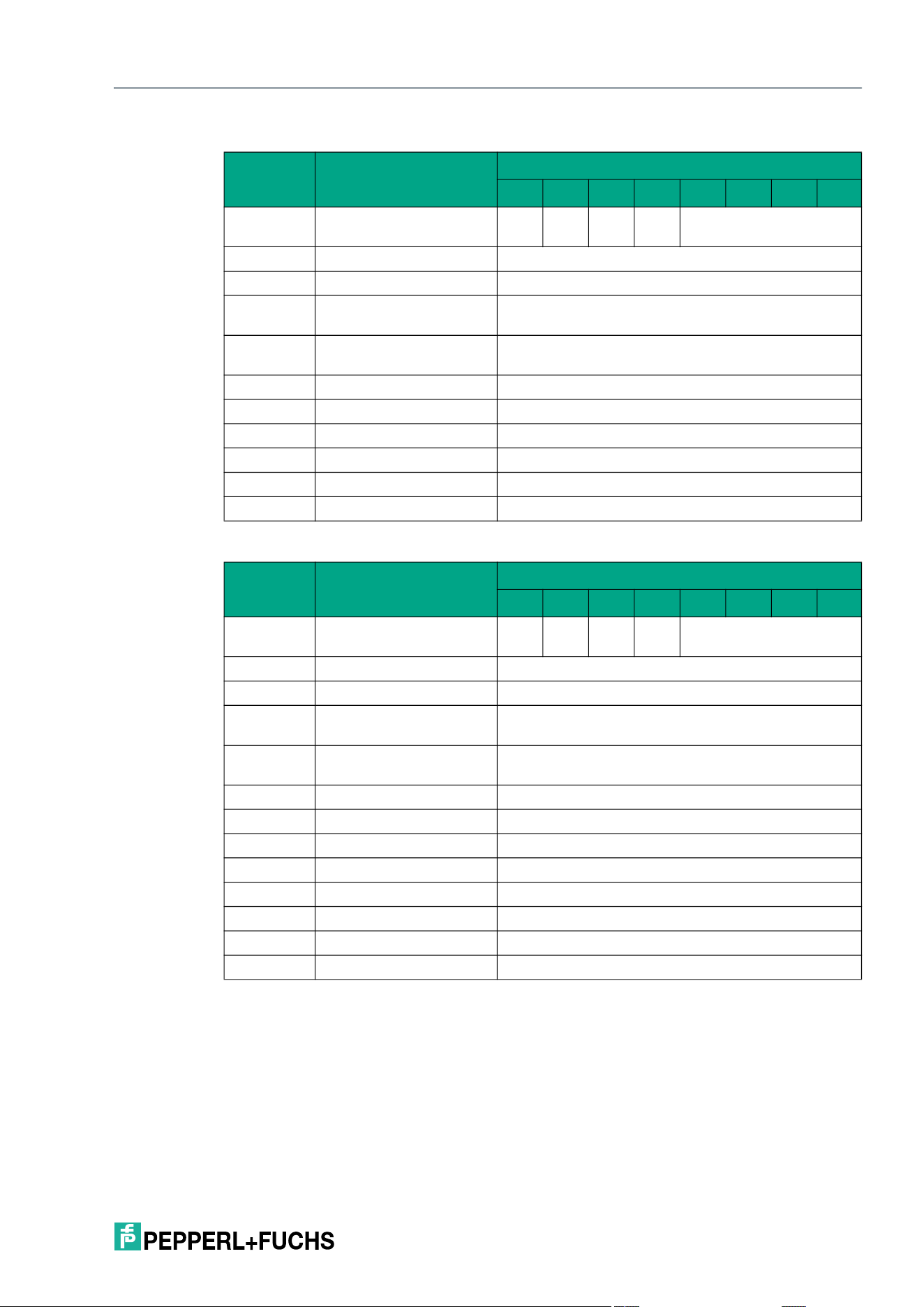
IQT3 / IQT4 Series
ExpertMode
2026-05
109
Response telegram 3 – status 16#0B (information frame mode)
Response telegram 4 – status 16#0F (long-form data format)
Selective Enhanced Get Configuration (XEG)
The XEG command has the command code 16#D6. In principle, the command functions in
exactly the same way as the EG command (16#68), but is only executed for a selected tag.
The parameters <UID Mask Byte 1> to <UID Mask Byte 8> are used to specify the UID of the
selected tag. <Length UID Mask in Bit> specifies the length of the UID in bits.
Byte Content
Bit number
7 6 5 4 3 2 1 0
Byte 0 Control byte / frame
length
D
S
U
M
U
D
0 16#0
Byte 1 Frame length 16#09
Byte 2 Fragmentation counter 16#00
Byte 3 Telegram length (high
byte)
16#00
Byte 4 Telegram length (low
byte)
16#06
Byte 5 Command 16#DD
Byte 6 Status 16#0B
Byte 7 Data 16#01 <Info Type>
Byte 8 Data <RSSI>
… Data 16#00
Byte 31 Data 16#00
Byte Content
Bit number
7 6 5 4 3 2 1 0
Byte 0 Control byte / frame
length
D
S
U
M
U
D
0 16#0
Byte 1 Frame length 16#0B
Byte 2 Fragmentation counter 16#00
Byte 3 Telegram length (high
byte)
16#00
Byte 4 Telegram length (low
byte)
16#08
Byte 5 Command 16#DD
Byte 6 Status 16#0F
Byte 7 Data <Number of Tags Byte 1>
Byte 8 Data <Number of Tags Byte 2>
Byte 9 Data <Number of Tags Byte 3>
Byte 10 Data <Number of Tags Byte 4>
… Data 16#00
Byte 31 Data 16#00
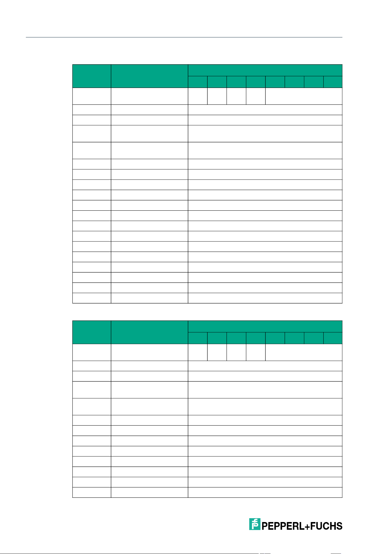
2026-05
110
IQT3 / IQT4 Series
ExpertMode
Command telegram (8 byte UID mask)
Response telegram 1 – status 16#00 (long-form data format)
Byte Content
Bit number
7 6 5 4 3 2 1 0
Byte 0 Control byte / frame
length
D
S
U
M
U
D
0 16#0
Byte 1 Frame length 16#11
Byte 2 Fragmentation counter 16#00
Byte 3 Telegram length (high
byte)
16#00
Byte 4 Telegram length (low
byte)
16#0E
Byte 5 Command 16#D6
Byte 6 Command parameter 16#00 <Length UID Mask in Bit (High Byte)>
Byte 7 Command parameter 16#40 <Length UID Mask in Bit (Low Byte)>
Byte 8 Command parameter <UID Mask Byte 1>
Byte 9 Command parameter <UID Mask Byte 2>
Byte 10 Command parameter <UID Mask Byte 3>
Byte 11 Command parameter <UID Mask Byte 4>
Byte 12 Command parameter <UID Mask Byte 5>
Byte 13 Command parameter <UID Mask Byte 6>
Byte 14 Command parameter <UID Mask Byte 7>
Byte 15 Command parameter <UID Mask Byte 8>
Byte 16 Command parameter 16#00 <Config Address>
… Command parameters 16#00
Byte 31 Command parameter 16#00
Byte Content
Bit number
7 6 5 4 3 2 1 0
Byte 0 Control byte / frame
length
D
S
U
M
U
D
0 16#0
Byte 1 Frame length 16#20
Byte 2 Fragmentation counter 16#01
Byte 3 Telegram length (high
byte)
16#00
Byte 4 Telegram length (low
byte)
16#1E
Byte 5 Command 16#D6
Byte 6 Status 16#00
Byte 7 Data 16#00 <Length UID in Bytes (High Byte)>
Byte 8 Data 16#08 <Length UID in Bytes (Low Byte)>
Byte 9 Data <UID Byte 1>
Byte 10 Data <UID Byte 2>
Byte 11 Data <UID Byte 3>
Byte 12 Data <UID Byte 4>
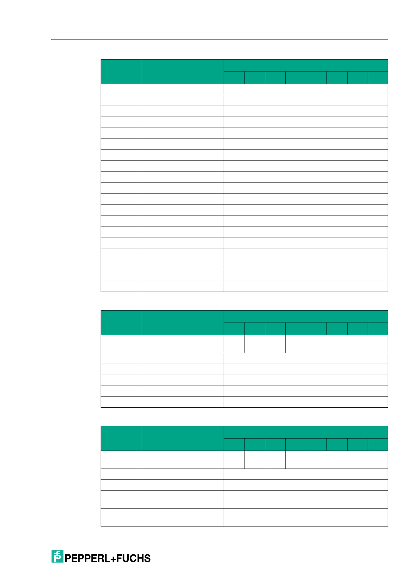
IQT3 / IQT4 Series
ExpertMode
2026-05
111
Response telegram 2 – status 16#00 (long-form data format):
Response telegram 3 – status 16#0B (information frame mode)
Byte 13 Data <UID Byte 5>
Byte 14 Data <UID Byte 6>
Byte 15 Data <UID Byte 7>
Byte 16 Data <UID Byte 8>
Byte 17 Data 16#00
Byte 18 Data 16#0E
Byte 19 Data <Info Flags>
Byte 20 Data <UID Byte 8>
Byte 21 Data <UID Byte 7>
Byte 22 Data <UID Byte 6>
Byte 23 Data <UID Byte 5>
Byte 24 Data <UID Byte 4>
Byte 25 Data <UID Byte 3>
Byte 26 Data <UID Byte 2>
Byte 27 Data <UID Byte 1>
Byte 28 Data <DSFID>
Byte 29 Data <AFI>
Byte 30 Data <VICC Memory Size (Number of Blocks -1)>
Byte 31 Data <VICC Memory Size (Block Size -1)>
Byte Content
Bit number
7 6 5 4 3 2 1 0
Byte 0 Control byte / frame
length
D
S
U
M
U
D
0 16#0
Byte 1 Frame length 16#04
Byte 2 Fragmentation counter 16#00
Byte 3 Data <IC Reference>
… Data 16#00
Byte 31 Data 16#00
Byte Content
Bit number
7 6 5 4 3 2 1 0
Byte 0 Control byte / frame
length
D
S
U
M
U
D
0 16#0
Byte 1 Frame length 16#09
Byte 2 Fragmentation counter 16#00
Byte 3 Telegram length (high
byte)
16#00
Byte 4 Telegram length (low
byte)
16#06
Byte Content
Bit number
7 6 5 4 3 2 1 0
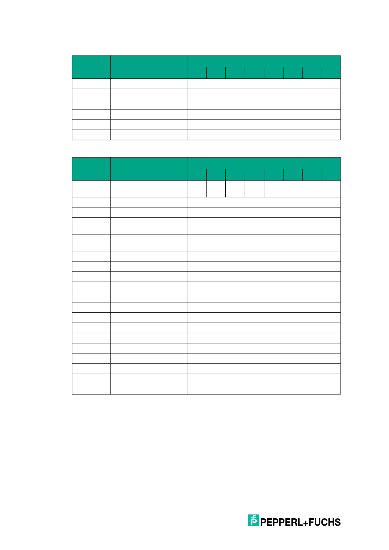
2026-05
112
IQT3 / IQT4 Series
ExpertMode
Response telegram 4 – status 16#05 (long-form data format)
Selective Single Set Configuration (XSC)
The XSC command has the command code 16#E1. In principle, the command functions in
exactly the same way as the SC command (16#12), but is only executed for a selected tag.
The parameters <UID Mask Byte 1> to <UID Mask Byte 8> are used to specify the UID of the
selected tag. <Length UID Mask in Bit> specifies the length of the UID in bits.
Byte 5 Command 16#D6
Byte 6 Status 16#0B
Byte 7 Data 16#01 <Info Type>
Byte 8 Data <RSSI>
… Data 16#00
Byte 31 Data 16#00
Byte Content
Bit number
7 6 5 4 3 2 1 0
Byte 0 Control byte / frame
length
D
S
U
M
U
D
0 16#0
Byte 1 Frame length 16#11
Byte 2 Fragmentation counter 16#00
Byte 3 Telegram length (high
byte)
16#00
Byte 4 Telegram length (low
byte)
16#0E
Byte 5 Command 16#D6
Byte 6 Status 16#05
Byte 7 Data 16#00 <Length UID in Bytes (High Byte)>
Byte 8 Data 16#08 <Length UID in Bytes (Low Byte)>
Byte 9 Data <UID Byte 1>
Byte 10 Data <UID Byte 2>
Byte 11 Data <UID Byte 3>
Byte 12 Data <UID Byte 4>
Byte 13 Data <UID Byte 5>
Byte 14 Data <UID Byte 6>
Byte 15 Data <UID Byte 7>
Byte 16 Data <UID Byte 8>
… Data 16#00
Byte 31 Data 16#00
Byte Content
Bit number
7 6 5 4 3 2 1 0
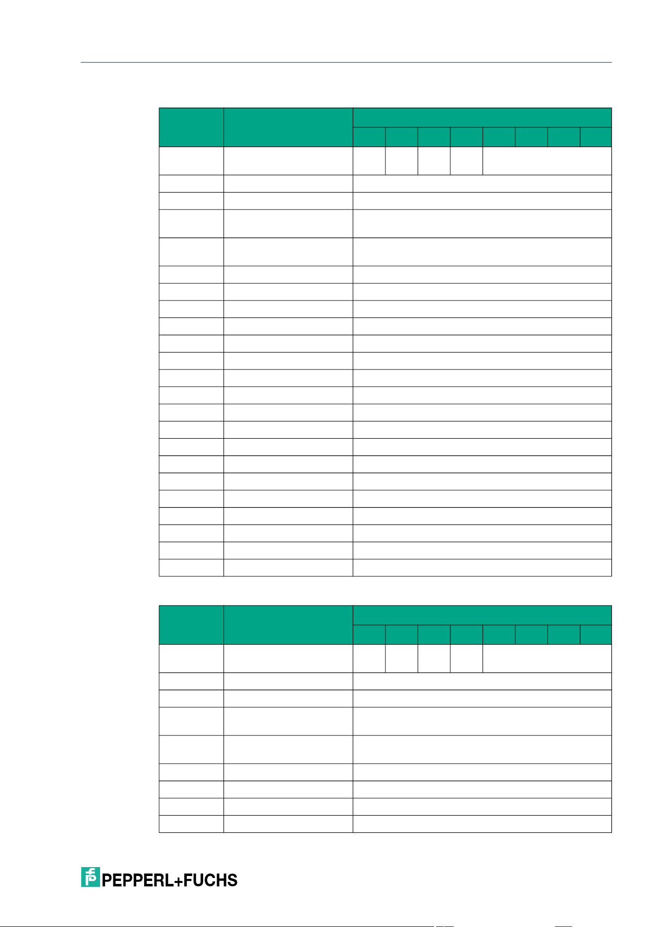
IQT3 / IQT4 Series
ExpertMode
2026-05
113
Command telegram (8 byte UID mask)
Response telegram 1 – status 16#00 (long-form data format)
Byte Content
Bit number
7 6 5 4 3 2 1 0
Byte 0 Control byte / frame
length
D
S
U
M
U
D
0 16#0
Byte 1 Frame length 16#15
Byte 2 Fragmentation counter 16#00
Byte 3 Telegram length (high
byte)
16#00
Byte 4 Telegram length (low
byte)
16#12
Byte 5 Command 16#E1
Byte 6 Command parameter 16#00 <Length UID Mask in Bit (High Byte)>
Byte 7 Command parameter 16#40 <Length UID Mask in Bit (Low Byte)>
Byte 8 Command parameter <UID Mask Byte 1>
Byte 9 Command parameter <UID Mask Byte 2>
Byte 10 Command parameter <UID Mask Byte 3>
Byte 11 Command parameter <UID Mask Byte 4>
Byte 12 Command parameter <UID Mask Byte 5>
Byte 13 Command parameter <UID Mask Byte 6>
Byte 14 Command parameter <UID Mask Byte 7>
Byte 15 Command parameter <UID Mask Byte 8>
Byte 16 Command parameter 16#00 <Config Address>
Byte 17 Command parameter <Lock>
Byte 18 Command parameter <DSFID / AFI>
Byte 19 Command parameter 16#00 (always)
Byte 20 Command parameter 16#00 (always)
… Command parameters 16#00
Byte 31 Command parameter 16#00
Byte Content
Bit number
7 6 5 4 3 2 1 0
Byte 0 Control byte / frame
length
D
S
U
M
U
D
0 16#0
Byte 1 Frame length 16#11
Byte 2 Fragmentation counter 16#00
Byte 3 Telegram length (high
byte)
16#00
Byte 4 Telegram length (low
byte)
16#0E
Byte 5 Command 16#E1
Byte 6 Status 16#00
Byte 7 Data 16#00 <Length UID in Bytes (High Byte)>
Byte 8 Data 16#08 <Length UID in Bytes (Low Byte)>
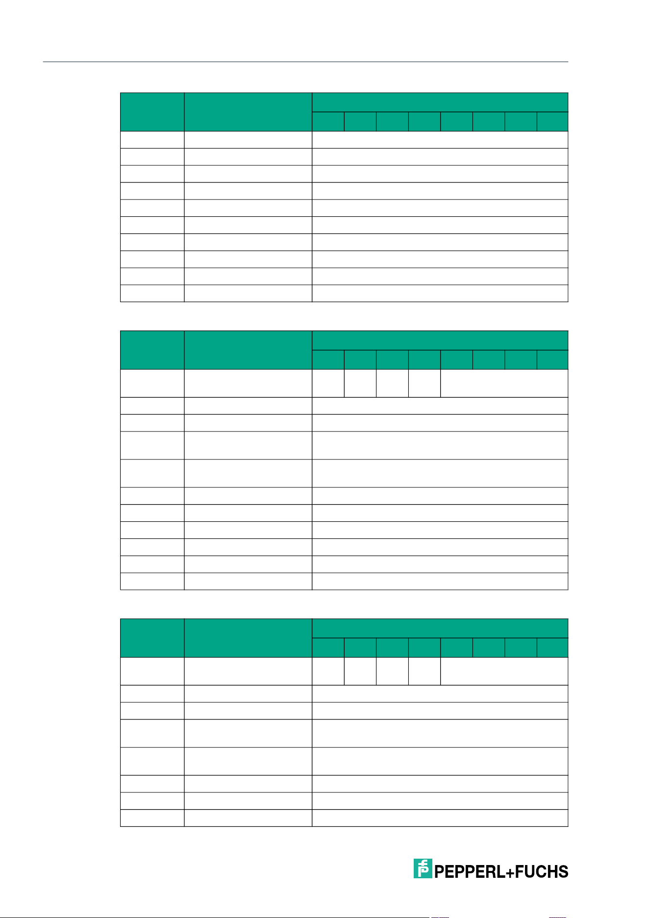
2026-05
114
IQT3 / IQT4 Series
ExpertMode
Response telegram 2 – status 16#0B (information frame mode
Response telegram 3 – status 16#0F (long-form data format)
Byte 9 Data <UID Byte 1>
Byte 10 Data <UID Byte 2>
Byte 11 Data <UID Byte 3>
Byte 12 Data <UID Byte 4>
Byte 13 Data <UID Byte 5>
Byte 14 Data <UID Byte 6>
Byte 15 Data <UID Byte 7>
Byte 16 Data <UID Byte 8>
… Data 16#00
Byte 31 Data 16#00
Byte Content
Bit number
7 6 5 4 3 2 1 0
Byte 0 Control byte / frame
length
D
S
U
M
U
D
0 16#0
Byte 1 Frame length 16#09
Byte 2 Fragmentation counter 16#00
Byte 3 Telegram length (high
byte)
16#00
Byte 4 Telegram length (low
byte)
16#06
Byte 5 Command 16#E1
Byte 6 Status 16#0B
Byte 7 Data 16#01 <Info Type>
Byte 8 Data <RSSI>
… Data 16#00
Byte 31 Data 16#00
Byte Content
Bit number
7 6 5 4 3 2 1 0
Byte 0 Control byte / frame
length
D
S
U
M
U
D
0 16#0
Byte 1 Frame length 16#0B
Byte 2 Fragmentation counter 16#00
Byte 3 Telegram length (high
byte)
16#00
Byte 4 Telegram length (low
byte)
16#08
Byte 5 Command 16#E1
Byte 6 Status 16#0F
Byte 7 Data <Number of Tags Byte 1>
Byte Content
Bit number
7 6 5 4 3 2 1 0
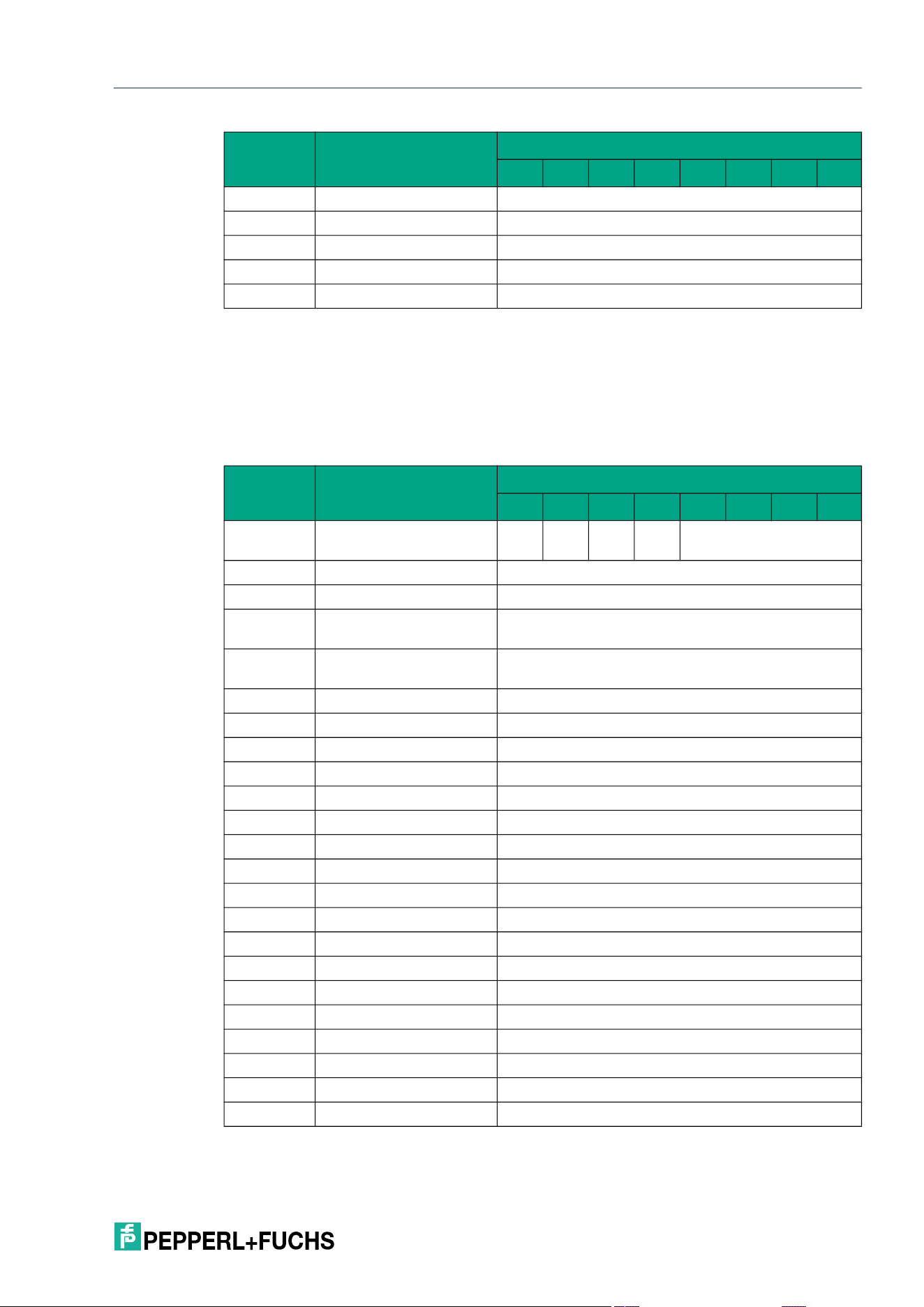
IQT3 / IQT4 Series
ExpertMode
2026-05
115
Selective Enhanced Set Configuration (XEC)
The XEC command has the command code 16#DA. In principle, the command functions in
exactly the same way as the EC command (16#66), but is only executed for a selected tag.
The parameters <UID Mask Byte 1> to <UID Mask Byte 8> are used to specify the UID of the
selected tag. <Length UID Mask in Bit> specifies the length of the UID in bits.
Command telegram (8 byte UID mask)
Byte 8 Data <Number of Tags Byte 2>
Byte 9 Data <Number of Tags Byte 3>
Byte 10 Data <Number of Tags Byte 4>
… Data 16#00
Byte 31 Data 16#00
Byte Content
Bit number
7 6 5 4 3 2 1 0
Byte 0 Control byte / frame
length
D
S
U
M
U
D
0 16#0
Byte 1 Frame length 16#15
Byte 2 Fragmentation counter 16#00
Byte 3 Telegram length (high
byte)
16#00
Byte 4 Telegram length (low
byte)
16#12
Byte 5 Command 16#DA
Byte 6 Command parameter 16#00 <Length UID Mask in Bit (High Byte)>
Byte 7 Command parameter 16#40 <Length UID Mask in Bit (Low Byte)>
Byte 8 Command parameter <UID Mask Byte 1>
Byte 9 Command parameter <UID Mask Byte 2>
Byte 10 Command parameter <UID Mask Byte 3>
Byte 11 Command parameter <UID Mask Byte 4>
Byte 12 Command parameter <UID Mask Byte 5>
Byte 13 Command parameter <UID Mask Byte 6>
Byte 14 Command parameter <UID Mask Byte 7>
Byte 15 Command parameter <UID Mask Byte 8>
Byte 16 Command parameter 16#00 <Config Address>
Byte 17 Command parameter <Lock>
Byte 18 Command parameter <DSFID / AFI>
Byte 19 Command parameter 16#00 (always)
Byte 20 Command parameter 16#00 (always)
… Command parameters 16#00
Byte 31 Command parameter 16#00
Byte Content
Bit number
7 6 5 4 3 2 1 0
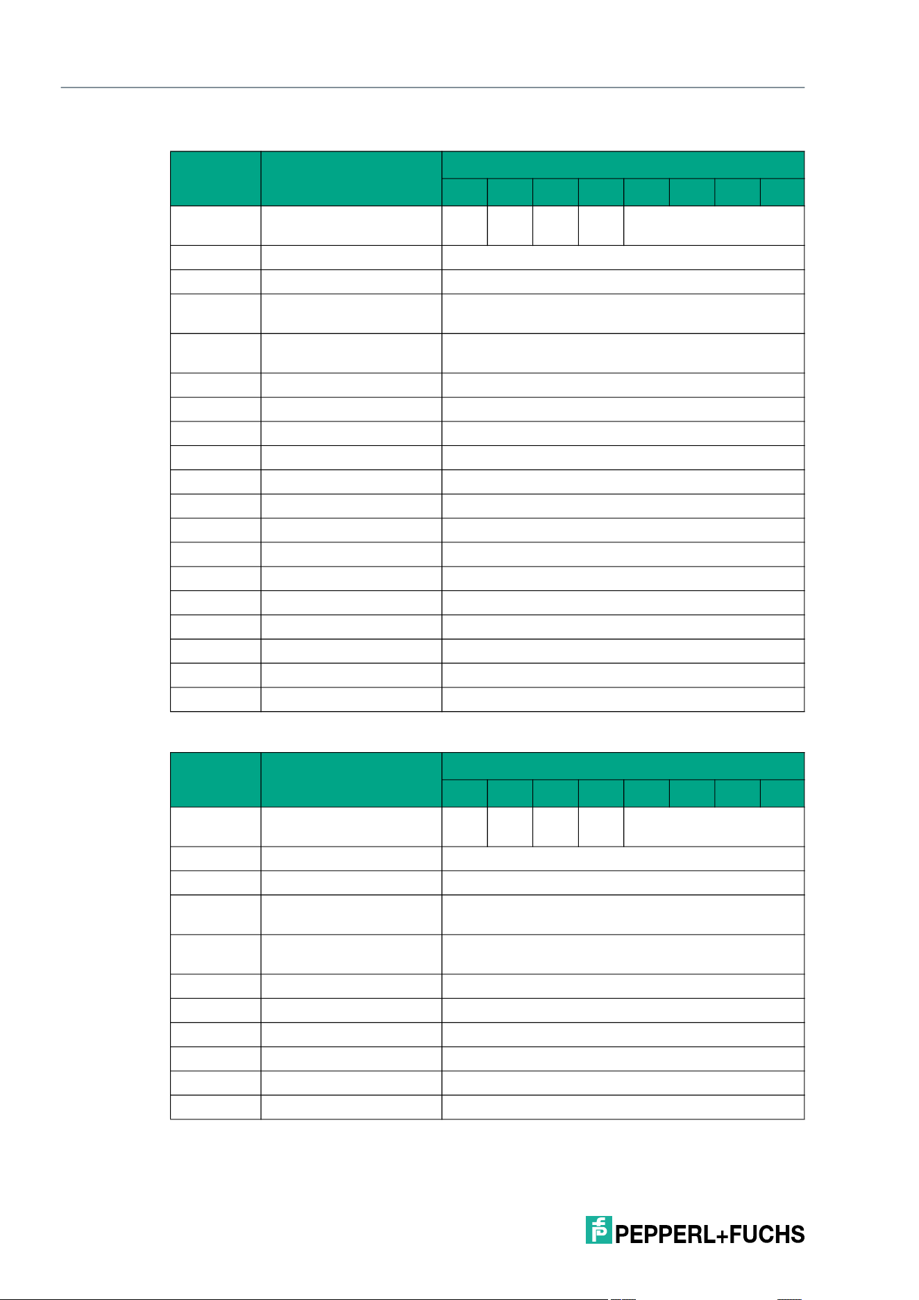
2026-05
116
IQT3 / IQT4 Series
ExpertMode
Response telegram 1 – status 16#00 (long-form data format)
Response telegram 2 – status 16#0B (information frame mode
Byte Content
Bit number
7 6 5 4 3 2 1 0
Byte 0 Control byte / frame
length
D
S
U
M
U
D
0 16#0
Byte 1 Frame length 16#11
Byte 2 Fragmentation counter 16#00
Byte 3 Telegram length (high
byte)
16#00
Byte 4 Telegram length (low
byte)
16#0E
Byte 5 Command 16#DA
Byte 6 Status 16#00
Byte 7 Data 16#00 <Length UID in Bytes (High Byte)>
Byte 8 Data 16#08 <Length UID in Bytes (Low Byte)>
Byte 9 Data <UID Byte 1>
Byte 10 Data <UID Byte 2>
Byte 11 Data <UID Byte 3>
Byte 12 Data <UID Byte 4>
Byte 13 Data <UID Byte 5>
Byte 14 Data <UID Byte 6>
Byte 15 Data <UID Byte 7>
Byte 16 Data <UID Byte 8>
… Data 16#00
Byte 31 Data 16#00
Byte Content
Bit number
7 6 5 4 3 2 1 0
Byte 0 Control byte / frame
length
D
S
U
M
U
D
0 16#0
Byte 1 Frame length 16#09
Byte 2 Fragmentation counter 16#00
Byte 3 Telegram length (high
byte)
16#00
Byte 4 Telegram length (low
byte)
16#06
Byte 5 Command 16#DA
Byte 6 Status 16#0B
Byte 7 Data 16#01 <Info Type>
Byte 8 Data <RSSI>
… Data 16#00
Byte 31 Data 16#00
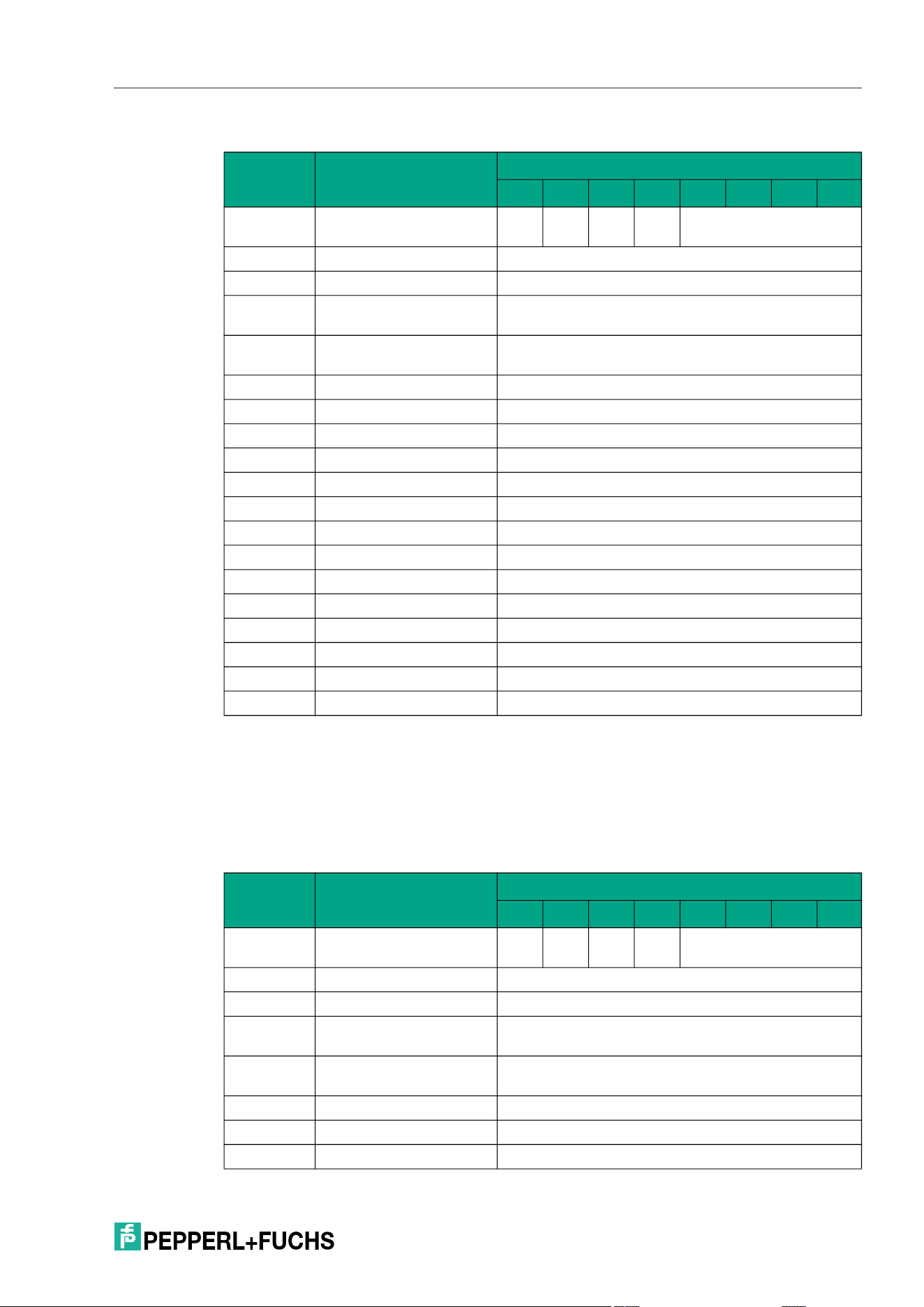
IQT3 / IQT4 Series
ExpertMode
2026-05
117
Response telegram 3 – status 16#05 (long-form data format):
Selective Fill Tag (XS#)
The XS# command has the command code 16#E7. In principle, the command functions in
exactly the same way as the S# command (16#AA), but is only executed for a selected tag.
The parameters <UID Mask Byte 1> to <UID Mask Byte 8> are used to specify the UID of the
selected tag. <Length UID Mask in Bit> specifies the length of the UID in bits.
Command telegram (8 byte UID mask)
Byte Content
Bit number
7 6 5 4 3 2 1 0
Byte 0 Control byte / frame
length
D
S
U
M
U
D
0 16#0
Byte 1 Frame length 16#11
Byte 2 Fragmentation counter 16#00
Byte 3 Telegram length (high
byte)
16#00
Byte 4 Telegram length (low
byte)
16#0E
Byte 5 Command 16#DA
Byte 6 Status 16#05
Byte 7 Data 16#00 <Length UID in Bytes (High Byte)>
Byte 8 Data 16#08 <Length UID in Bytes (Low Byte)>
Byte 9 Data <UID Byte 1>
Byte 10 Data <UID Byte 2>
Byte 11 Data <UID Byte 3>
Byte 12 Data <UID Byte 4>
Byte 13 Data <UID Byte 5>
Byte 14 Data <UID Byte 6>
Byte 15 Data <UID Byte 7>
Byte 16 Data <UID Byte 8>
… Data 16#00
Byte 31 Data 16#00
Byte Content
Bit number
7 6 5 4 3 2 1 0
Byte 0 Control byte / frame
length
D
S
U
M
U
D
0 16#0
Byte 1 Frame length 16#15
Byte 2 Fragmentation counter 16#00
Byte 3 Telegram length (high
byte)
16#00
Byte 4 Telegram length (low
byte)
16#12
Byte 5 Command 16#E7
Byte 6 Command parameter 16#00 <Length UID Mask in Bit (High Byte)>
Byte 7 Command parameter 16#40 <Length UID Mask in Bit (Low Byte)>
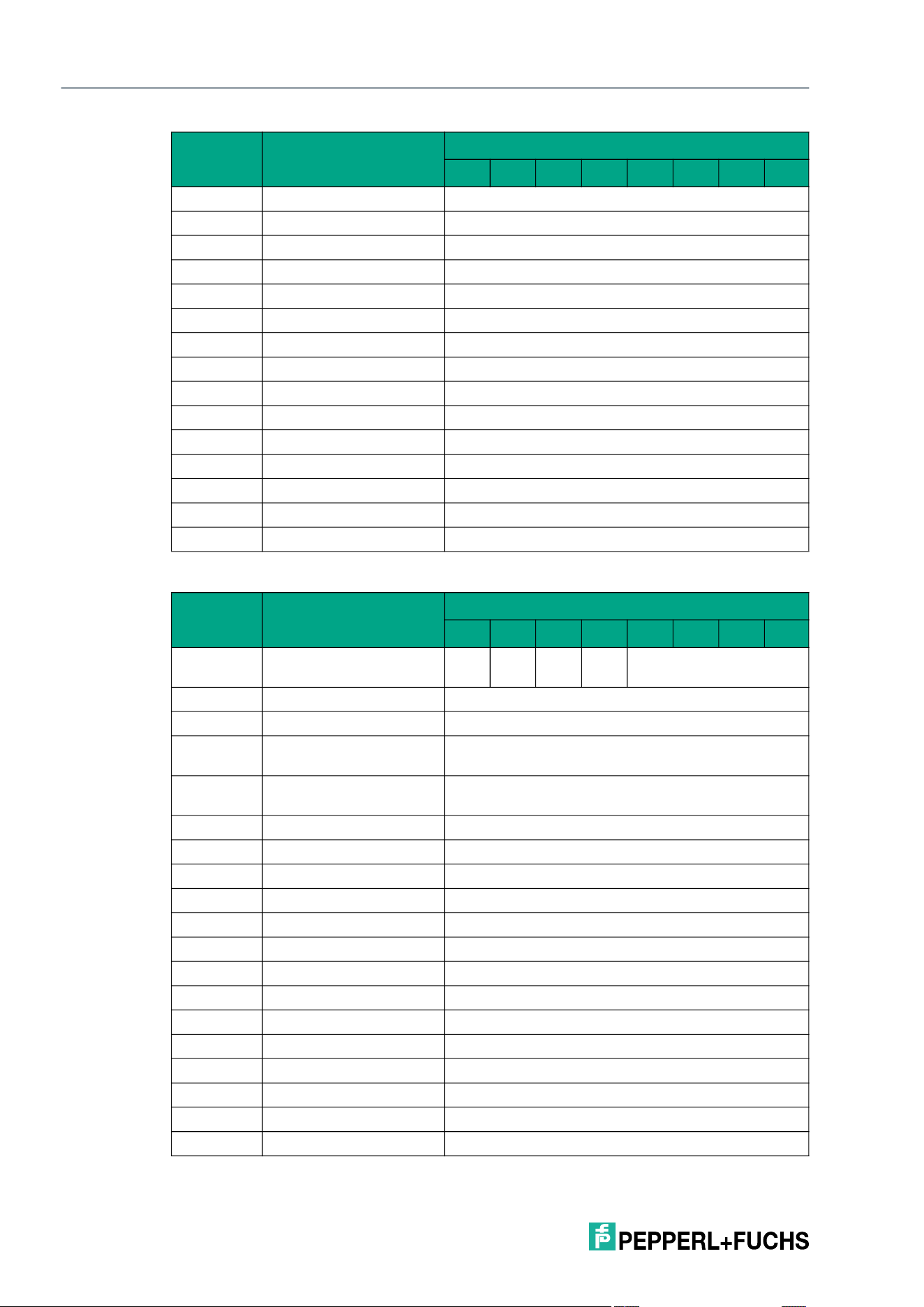
2026-05
118
IQT3 / IQT4 Series
ExpertMode
Response telegram 1 – status 16#00 (long-form data format)
Byte 8 Command parameter <UID Mask Byte 1>
Byte 9 Command parameter <UID Mask Byte 2>
Byte 10 Command parameter <UID Mask Byte 3>
Byte 11 Command parameter <UID Mask Byte 4>
Byte 12 Command parameter <UID Mask Byte 5>
Byte 13 Command parameter <UID Mask Byte 6>
Byte 14 Command parameter <UID Mask Byte 7>
Byte 15 Command parameter <UID Mask Byte 8>
Byte 16 Command parameter 16#00 <Start Address (High Byte)>
Byte 17 Command parameter 16#00 <Start Address (Low Byte)>
Byte 18 Command parameter 16#00 <Number of Bytes (High Byte)>
Byte 19 Command parameter 16#04 <Number of Bytes (Low Byte)>
Byte 20 Command parameter <FillSign>
… Command parameters 16#00
Byte 31 Command parameter 16#00
Byte Content
Bit number
7 6 5 4 3 2 1 0
Byte 0 Control byte / frame
length
D
S
U
M
U
D
0 16#0
Byte 1 Frame length 16#11
Byte 2 Fragmentation counter 16#00
Byte 3 Telegram length (high
byte)
16#00
Byte 4 Telegram length (low
byte)
16#0E
Byte 5 Command 16#E7
Byte 6 Status 16#00
Byte 7 Data 16#00 <Length UID in Bytes (High Byte)>
Byte 8 Data 16#08 <Length UID in Bytes (Low Byte)>
Byte 9 Data <UID Byte 1>
Byte 10 Data <UID Byte 2>
Byte 11 Data <UID Byte 3>
Byte 12 Data <UID Byte 4>
Byte 13 Data <UID Byte 5>
Byte 14 Data <UID Byte 6>
Byte 15 Data <UID Byte 7>
Byte 16 Data <UID Byte 8>
… Data 16#00
Byte 31 Data 16#00
Byte Content
Bit number
7 6 5 4 3 2 1 0
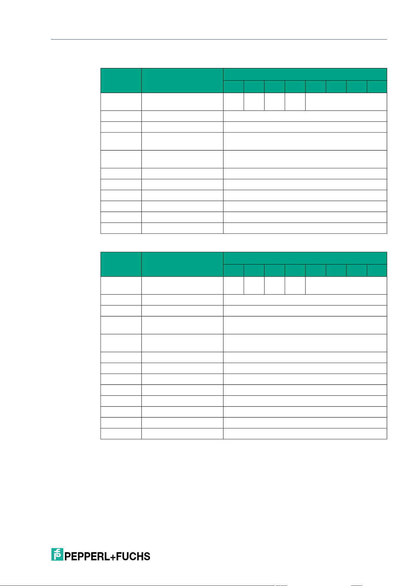
IQT3 / IQT4 Series
ExpertMode
2026-05
119
Response telegram 2 – status 16#0B (information frame mode
Response telegram 3 – status 16#0F (long-form data format)
8.6.2 System Commands
Quit (QU)
The "Quit" command has the command code 16#02 and stops the execution of an active com-
mand on the device. This terminates the Enhanced Read or Enhanced Write commands. Suc-
cessful execution of the command is indicated by a telegram with the status value 16#00.
Byte Content
Bit number
7 6 5 4 3 2 1 0
Byte 0 Control byte / frame
length
D
S
U
M
U
D
0 16#0
Byte 1 Frame length 16#09
Byte 2 Fragmentation counter 16#00
Byte 3 Telegram length (high
byte)
16#00
Byte 4 Telegram length (low
byte)
16#06
Byte 5 Command 16#E7
Byte 6 Status 16#0B
Byte 7 Data 16#01 <Info Type>
Byte 8 Data <RSSI>
… Data 16#00
Byte 31 Data 16#00
Byte Content
Bit number
7 6 5 4 3 2 1 0
Byte 0 Control byte / frame
length
D
S
U
M
U
D
0 16#0
Byte 1 Frame length 16#0B
Byte 2 Fragmentation counter 16#00
Byte 3 Telegram length (high
byte)
16#00
Byte 4 Telegram length (low
byte)
16#08
Byte 5 Command 16#E7
Byte 6 Status 16#0F
Byte 7 Data <Number of Tags Byte 1>
Byte 8 Data <Number of Tags Byte 2>
Byte 9 Data <Number of Tags Byte 3>
Byte 10 Data <Number of Tags Byte 4>
… Data 16#00
Byte 31 Data 16#00
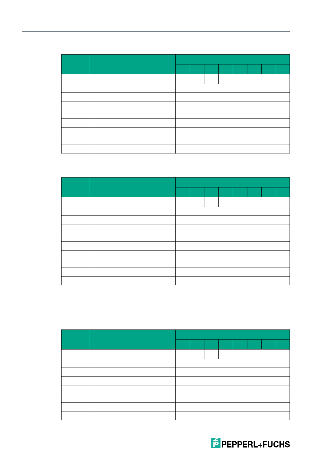
2026-05
120
IQT3 / IQT4 Series
ExpertMode
Command telegram
Response telegram 1 – status 16#00
Version (VE)
The "VE" command has the command code 16#03 and reads out the device firmware version.
Command telegram
Byte Content
Bit number
7 6 5 4 3 2 1 0
Byte 0 Control byte / frame length D
S
U
M
U
D
0 16#0
Byte 1 Frame length 16#06
Byte 2 Fragmentation counter 16#00
Byte 3 Telegram length (high byte) 16#00
Byte 4 Telegram length (low byte) 16#03
Byte 5 Command 16#02
Byte 6 Not relevant 16#00
... Not relevant 16#00
Byte 31 Not relevant 16#00
Table 8.3
Byte Content
Bit number
7 6 5 4 3 2 1 0
Byte 0 Control byte / frame length D
S
U
M
U
D
0 16#0
Byte 1 Frame length 16#07
Byte 2 Fragmentation counter 16#00
Byte 3 Telegram length (high byte) 16#00
Byte 4 Telegram length (low byte) 16#04
Byte 5 Command 16#02
Byte 6 Status 16#00
Byte 7 Not relevant 16#00
... Not relevant 16#00
Byte 31 Not relevant 16#00
Table 8.4
Byte Content
Bit number
7 6 5 4 3 2 1 0
Byte 0 Control byte / frame length D
S
U
M
U
D
0 16#0
Byte 1 Frame length 16#06
Byte 2 Fragmentation counter 16#00
Byte 3 Telegram length (high byte) 16#00
Byte 4 Telegram length (low byte) 16#03
Byte 5 Command 16#03
Byte 6 Not relevant 16#00
... Not relevant 16#00
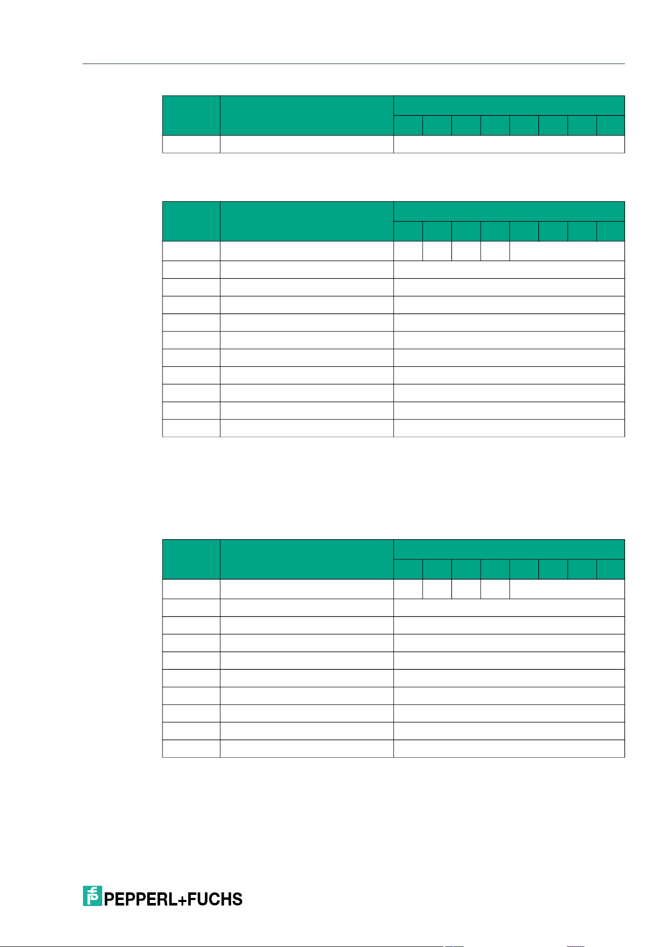
IQT3 / IQT4 Series
ExpertMode
2026-05
121
Response telegram 1 – status 16#00
Change Tag (CT)
The "CT" command has the command code 16#04 and sets the tag type with which the
read/write device communicates the read unit. The delivery status is type "20."
Command telegram
Byte 31 Not relevant 16#00
Table 8.5
Byte Content
Bit number
7 6 5 4 3 2 1 0
Byte 0 Control byte / frame length D
S
U
M
U
D
0 16#0
Byte 1 Frame length <Frame Length>
Byte 2 Fragmentation counter 16#00
Byte 3 Telegram length (high byte) <Telegram Length (High Byte)>
Byte 4 Telegram length (low byte) <Telegram Length (Low Byte)>
Byte 5 Command 16#03
Byte 6 Status 16#00
Byte 7 Version byte 1 16#XX
... ... 16#XX
Byte X Version byte X 16#XX
Byte 31 Not relevant 16#00
Table 8.6
Byte Content
Bit number
7 6 5 4 3 2 1 0
Byte 0 Control byte / frame length D
S
U
M
U
D
0 16#0
Byte 1 Frame length 16#07
Byte 2 Fragmentation counter 16#00
Byte 3 Telegram length (high byte) 16#00
Byte 4 Telegram length (low byte) 16#04
Byte 5 Command 16#04
Byte 6 Tag type 16#14
Byte 7 Not relevant 16#00
... Not relevant 16#00
Byte 31 Not relevant 16#00
Table 8.7
Byte Content
Bit number
7 6 5 4 3 2 1 0
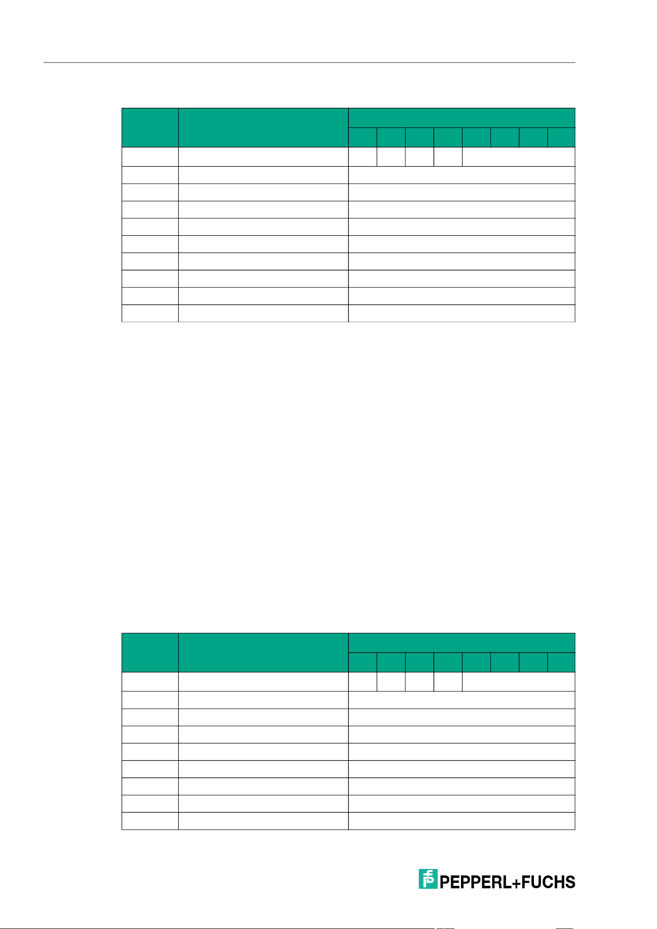
2026-05
122
IQT3 / IQT4 Series
ExpertMode
Response telegram 1 – status 16#00
The tag type can be set via a parameter, see "Tag type (CT)" on page 128.
8.6.3 Configuration Commands
The "Read Parameter" and "Write Parameter" configuration commands can be used to read or
change the parameters of the device.
All parameter values except parameter "TI" are stored in a non-volatile memory and remain
unchanged after a power interruption. The response to a configuration command is a status
message from the read/write device. During the read operation, a status message and the cor-
responding data are received as the response.
A system code is required to access the parameters on the device. This distinguishes between
other systems in which parameters can be changed. This device uses the system code "Q"
(16#51).
8.6.3.1 Basic Command Structure
Read Parameter (RP)
The "Read Parameter" (RP) command has the command code 16#BE and reads a device
parameter. The response to the configuration command is a status message from the RFID
read/write device and the corresponding data.
Command telegram
Byte Content
Bit number
7 6 5 4 3 2 1 0
Byte 0 Control byte / frame length D
S
U
M
U
D
0 16#0
Byte 1 Frame length 16#07
Byte 2 Fragmentation counter 16#00
Byte 3 Telegram length (high byte) 16#00
Byte 4 Telegram length (low byte) 16#04
Byte 5 Command 16#04
Byte 6 Status 16#00
Byte 7 Not relevant 16#00
... Not relevant 16#00
Byte 31 Not relevant 16#00
Table 8.8
Byte Content
Bit number
7 6 5 4 3 2 1 0
Byte 0 Control byte / frame length D
S
U
M
U
D
0 <FrameLength>
Byte 1 Frame length <FrameLength>
Byte 2 Fragmentation counter 16#00
Byte 3 Telegram length (high byte) <TelegramLength (High Byte)>
Byte 4 Telegram length (low byte) <TelegramLength (Low Byte)>
Byte 5 Command 16#BE
Byte 6 System Code 16#51 "Q"
Byte 7 Parameter name (high byte) <ParameterName (High Byte)>
Byte 8 Parameter name (low byte) <ParameterName (Low Byte)>
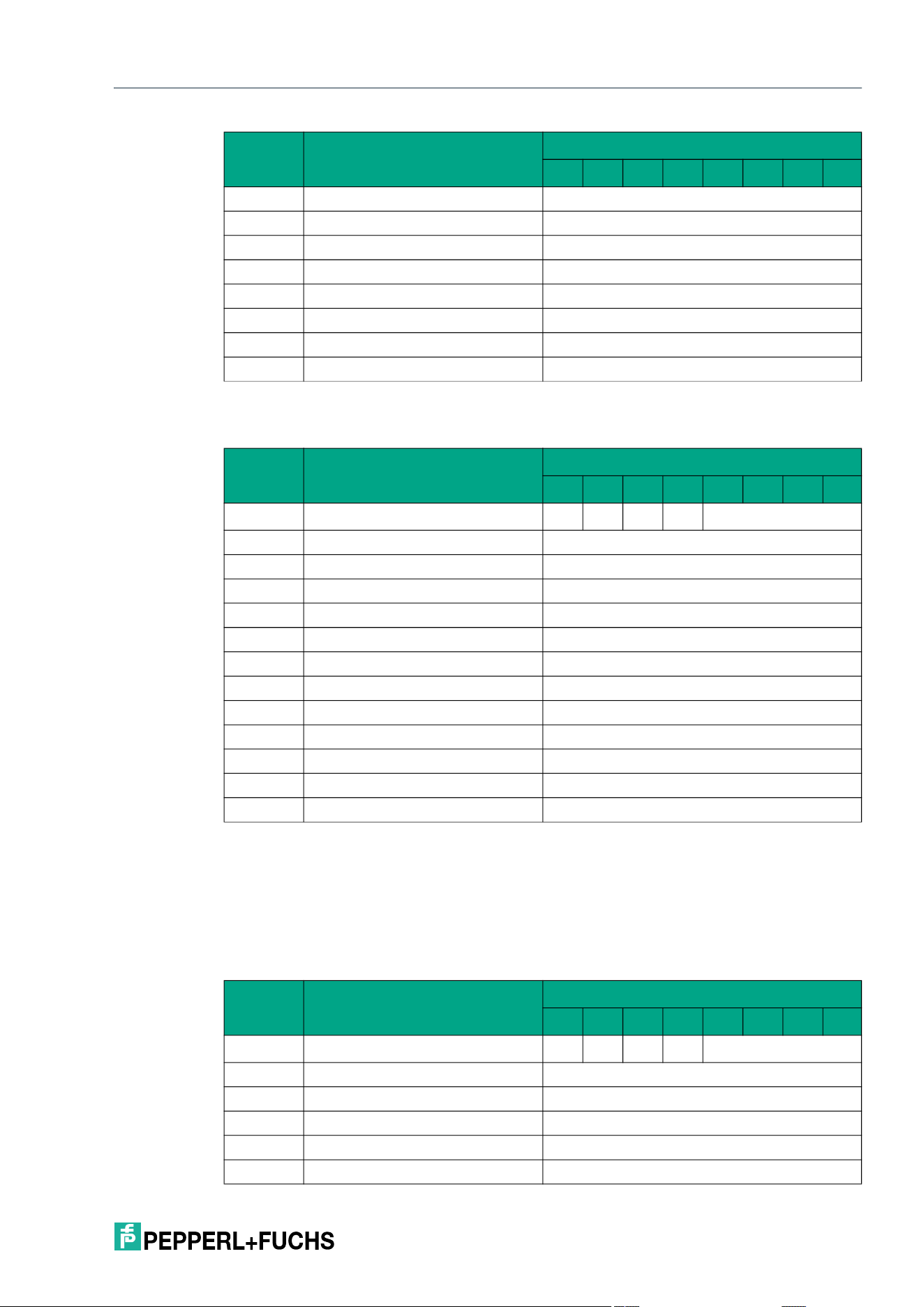
IQT3 / IQT4 Series
ExpertMode
2026-05
123
Response telegram
Write Parameter (WP)
The "Write Parameter" (WP) command has the command code 16#BF. The command can be
used to change device parameters. The response to the configuration command is a status
message from the RFID read/write device.
Command telegram
Byte 9 Length Parameter (High Byte) <ParameterLength (High Byte)>
Byte 10 Length Parameter (Low Byte) <ParameterLength (Low Byte)>
Byte 11 Parameter Data Byte 1 <Parameter Data Byte 1>
Byte 12 Parameter Data Byte 2 <Parameter Data Byte 2>
... ... ...
... Parameter Data Byte X <Parameter Data Byte X>
... Not relevant 16#00
Byte 31 Not relevant 16#00
Table 8.9
Byte Content
Bit number
7 6 5 4 3 2 1 0
Byte 0 Control byte / frame length D
S
U
M
U
D
0 <FrameLength>
Byte 1 Frame length <FrameLength>
Byte 2 Fragmentation counter <FragmentationCounter>
Byte 3 Telegram length (high byte) <TelegramLength (High Byte)>
Byte 4 Telegram length (low byte) <TelegramLength (Low Byte)>
Byte 5 Command 16#BE
Byte 6 Status <Status>
Byte 7 Parameter name (high byte) <Parameter Data Byte 1>
Byte 8 Parameter name (low byte) <Parameter Data Byte 2>
... ... ...
... Parameter data byte X <Parameter Data Byte X>
... Not relevant 16#00
Byte 31 Not relevant 16#00
Table 8.10
Byte Content
Bit number
7 6 5 4 3 2 1 0
Byte 0 Control byte / frame length D
S
U
M
U
D
0 <FrameLength>
Byte 1 Frame length <FrameLength>
Byte 2 Fragmentation counter 16#00
Byte 3 Telegram length (high byte) <TelegramLength (High Byte)>
Byte 4 Telegram length (low byte) <TelegramLength (Low Byte)>
Byte 5 Command 16#BF
Byte Content
Bit number
7 6 5 4 3 2 1 0
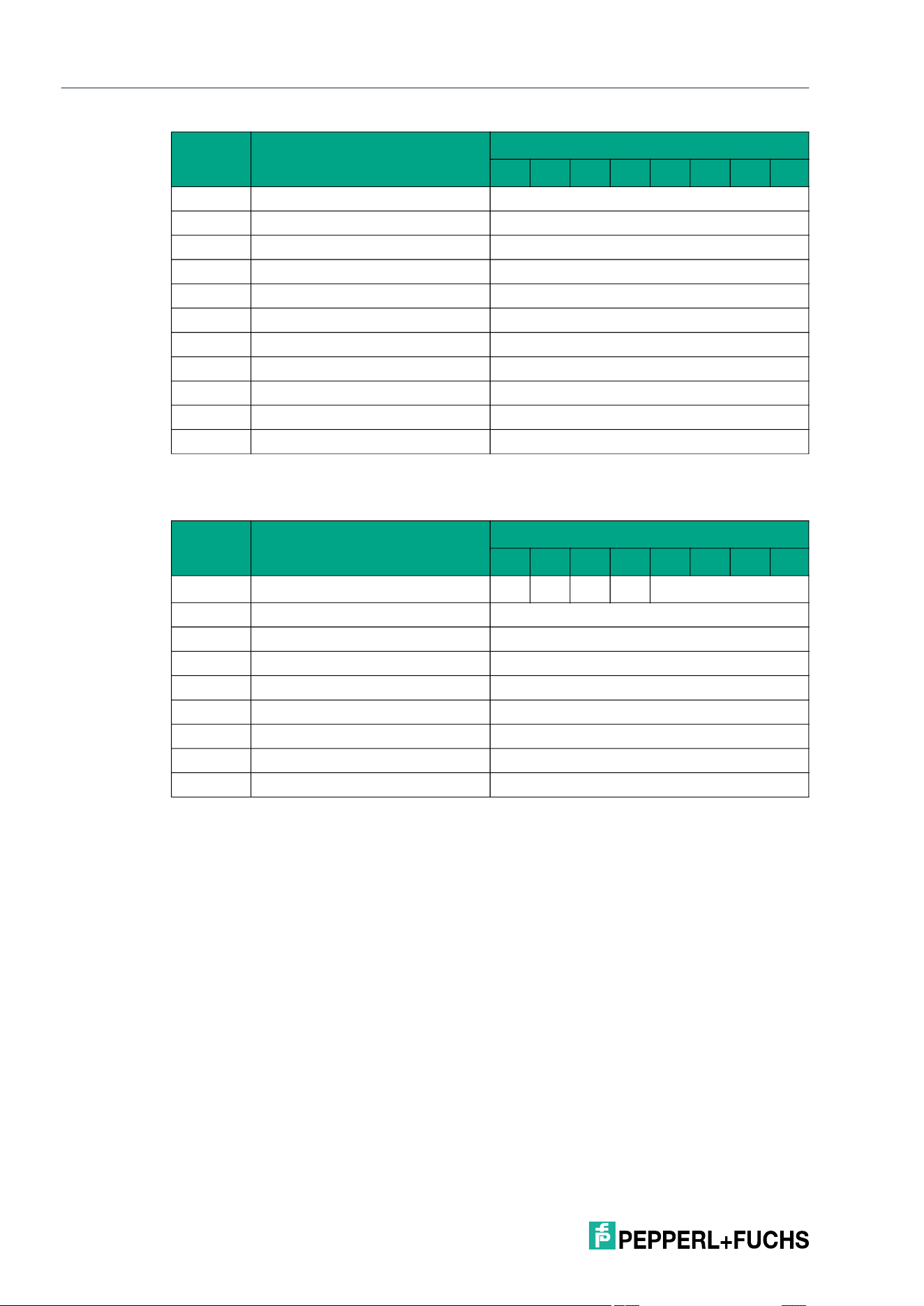
2026-05
124
IQT3 / IQT4 Series
ExpertMode
Response telegram
Byte 6 System code 16#51 "Q"
Byte 7 Parameter name (high byte) <ParameterName (High Byte)>
Byte 8 Parameter name (low byte) <ParameterName (Low Byte)>
Byte 9 Length parameter (high byte) <LengthParameter (High Byte)>
Byte 10 Length parameter (low byte) <LengthParameter (Low Byte)>
Byte 11 Parameter data byte 1 <Parameter Data Byte 1>
Byte 12 Parameter data byte 2 <Parameter Data Byte 2>
... ... ...
... Parameter data byte X <Parameter Data Byte X>
... Not relevant 16#00
Byte 31 Not relevant 16#00
Table 8.11
Byte Content
Bit number
7 6 5 4 3 2 1 0
Byte 0 Control byte / frame length D
S
U
M
U
D
0 16#0
Byte 1 Frame length 16#07
Byte 2 Fragmentation counter 16#00
Byte 3 Telegram length (high byte) 16#00
Byte 4 Telegram length (low byte) 16#04
Byte 5 Command 16#BF
Byte 6 Status 16#00
... Not relevant 16#00
Byte 31 Not relevant 16#00
Table 8.12
Byte Content
Bit number
7 6 5 4 3 2 1 0
IQT3 / IQT4 Series
ExpertMode
2026-05
125
8.6.3.2 Parameter Overview
With the Read Parameter RP and Write Parameter WP configuration commands, you can read
or write the following parameters:
Abbrevi-
ation
Command
code Parameter description Read/write
Default
value System
AF 16#4146 AFI
Filter on AFI for tag
access
Read + write 16#00 IQT3, IQT4
BB 16#4242 Back to Box
Reset all parameters to
factory setting
Write -
IQT3
1
, IQT4
CT 16#4654 Tag Type (Service)
Set tag type
Read + write 16#14 IQT3, IQT4
DA 16#4441 Device Address
Set device address
Read + write 16#FF
IQT3
1<Default
¬¹ Font>
, IQT4
DD 16#4444 Diagnosis Data (Service)
Read the combined diag-
nostic data of parameters
OH, ST, TE, and VO
Read -
IQT3
1<Default
¬¹ Font>
, IQT4
DN 16#444E Device Serial Number
Read the device serial
number
Read -
IQT3
1<Default
¬¹ Font>
, IQT4
DR 16#4452 Data Rate
Set transmission rate
Read + write 16#00 IQT3, IQT4
DS 16#4453 Data Swap
Rotate data blocks in
blocks
Read + write 16#01
IQT3
1<Default
¬¹ Font>
, IQT4
E5 16#4535 Tag Lost Smoothing
Set the number of unsuc-
cessful attempts to
access a tag before a Sta-
tus 5 message is issued
Read + write 16#05 IQT3, IQT4
ED 16#4544 Standalone End Delimiter
(Service)
Select the end delimiter
Read + write 16#xx
IQT3
1<Default
¬¹ Font>
, IQT4
FR 16#4652 Sequence Mode (Ser-
vice)
Set the behavior for write
accesses
Read + write 16#01
IQT3
1<Default
¬¹ Font>
, IQT4
IF 16#4946 Information Frame Mode
Output additional informa-
tion about access to the
tag
Read 16#01 IQT3, IQT4
LM 16#4C4D LED Masking
Setting for displaying the
operating status via LEDs
Read + write 16#0000
IQT3
1<Default
¬¹ Font>
, IQT4
MF 16#4D46 Reflected Power (Service)
Measurement of the
reflected transmitter radi-
ated power
Read -
IQT3
1<Default
¬¹ Font>
, IQT4
ND 16#4E44 Noise Detection Level
Setting for displaying the
threshold for noise via
LED
Read + write 16#32
IQT3
1<Default
¬¹ Font>
, IQT4
2026-05
126
IQT3 / IQT4 Series
ExpertMode
NT 16#4E54 Number of Tags to Find
Setting for the abort crite-
rion for read/write com-
mands
Read + write 16#FF IQT3, IQT4
OH 16#4F48 Operating Hours
Read the operating hours
counter
Read - IQT3, IQT4
PT 16#5054 Transmission Power
Setting for the device's
transmitter radiated power
Read + write 16#0004 /
16#0001
IQT3, IQT4
QV 16#5156 Reply Frame Mode
Protocol mode setting
Read 16#4D IQT3, IQT4
QW 16#5157 Q-Value
Setting for the time slots
for access to tags
Read + write 16#00 IQT3, IQT4
RC 16#5243 Region Code (Service)
Reading the country code
Read 16#01
IQT3
1<Default
¬¹ Font>
, IQT4
RD 16#5244 Reset to Default
Resetting certain parame-
ters to factory setting
Write - IQT3, IQT4
RL 16#524C RSSI Lower Limit
Setting the lower RSSI
threshold value
Read + write 16#00
IQT3
1<Default
¬¹ Font>
, IQT4
RU 16#5255 RSSI Upper Limit
Setting the upper RSSI
threshold value
Read + write 16#64
IQT3
1<Default
¬¹ Font>
, IQT4
RV 16#5256 SVN Revision (Service)
Reading the software revi-
sion number
Read -
IQT3
1<Default
¬¹ Font>
, IQT4
SN 16#534E Serial Number (Service)
Reading the serial num-
ber of the microcontroller
Read -
IQT3
1<Default
¬¹ Font>
, IQT4
ST 16#5354 Frontend State
Reading the front-end sta-
tus
Read 16#00 IQT3, IQT4
T2 16#5432 Application Tag
Setting the application
identifier
Read + write Your auto-
mation,
our pas-
sion.
IQT3
1<Default
¬¹ Font>
, IQT4
T3 16#5433 Function Tag
Setting the function identi-
fier
Read + write ***
IQT3
1<Default
¬¹ Font>
, IQT4
T4 16#5434 Location Tag
Setting the location identi-
fier
Read + write ***
IQT3
1<Default
¬¹ Font>
, IQT4
T5 16#5435 Installation Tag
Setting the installation
identifier
Read + write ***
IQT3
1<Default
¬¹ Font>
, IQT4
TA 16#5441 Tries Allowed
Setting the number of
attempts to access tags
Read + write 16#02 IQT3, IQT4
TE 16#5445 Temperature
Reading the device tem-
perature
Read - IQT3, IQT4
Abbrevi-
ation
Command
code Parameter description Read/write
Default
value System
IQT3 / IQT4 Series
ExpertMode
2026-05
127
The parameters are saved in the read/write device as nonvolatile.
8.6.3.3 Parameters
AFI (AF)
The AF parameter can be used to filter tags based on the AFI. Read/write commands are only
executed for tags whose AFI matches the filter value.
Back to Box (BB)
The BB parameter can be used to reset all read/write device settings to the factory setting.
Tag type (CT)
The CT parameter sets the type of tag with which the read/write device communicates.
For supported read/write tags, please see see chapter 6.2.
TI 16#5449 Tag ID Filter
Setting the filter to the UID
Read + write - IQT3, IQT4
TO 16#544F Overtemperature Han-
dling
Setting the device behav-
ior in the event of excess
temperature
Read + write 16#00 IQT3, IQT4
UB 16#5542 Host Uart Baudrate (Ser-
vice)
Setting the baud rate
Read + write 16#00009
600
IQT3
1<Default
¬¹ Font>
, IQT4
UT 16#5554 Host Uart Timeout (Ser-
vice)
Setting the timeout
Read + write 16#0064
IQT3
1<Default
¬¹ Font>
, IQT4
VO 16#564F Voltages
Reading internal voltage
and current values
Read -
IQT3
1<Default
¬¹ Font>
, IQT4
1.from SW Rev. 26
Abbrevi-
ation
Command
code Parameter description Read/write
Default
value System
Parameter abbre-
viation:
AF
Parameter length: 1 byte
Default: 16#00 = all tags respond
Value range: 16#00 … 16#FF
Parameter abbre-
viation:
BB
Factory setting: See chapter 8.6.3.2
Parameter abbre-
viation:
CT (16#4354)
Parameter length: 1 byte
Default: 16#14
Value range: 16#14 ... 16#26; 16#32; 16#33

2026-05
128
IQT3 / IQT4 Series
ExpertMode
Device Address (DA)
The DA parameter can be used to set the device address of the read/write device.
P+F Serial Number (DN)
The DN parameter can be used to read the serial number of the read/write device.
Data Rate (DR)
The DR parameter sets the data transmission rate between the read/write device and the tag.
The "fast read mode" data transmission rate is supported by
• Pepperl+Fuchs tag types IQC21,-33, -37, and -50, see chapter 6.2.
• Tag with access to at least 2 memory blocks
Data Swap (DS)
The DS parameter can be used to set the orientation of the data in a block of the user memory.
For a tag with a block size of 4 bytes, the data can be oriented as follows.
Note
The tag type can be changed using the CT system command see "Change Tag (CT)" on page
121.
Parameter abbre-
viation:
DA
Parameter length: 1 byte
Default: 16#FF
Value range: 16#00 … 16#FF
Parameter abbre-
viation:
DN
Parameter length: 14 bytes
Parameter abbre-
viation:
DR (16#4452)
Parameter length: 1 byte
Default: 16#00
Value range: 0 (16#00) = normal [26 kilobit/s]
1 (16#01) = fast read mode in accordance with ISO/IEC 15693-2 X2
[53 kilobit/s]
Parameter abbre-
viation:
DS
Parameter length: 1 byte
Default: 16#01
Value range: 16#00 = No byte-by-byte exchange of data in the user memory
16#01 = Byte-by-byte exchange of blocks in the user memory (compatible
with IQT1)
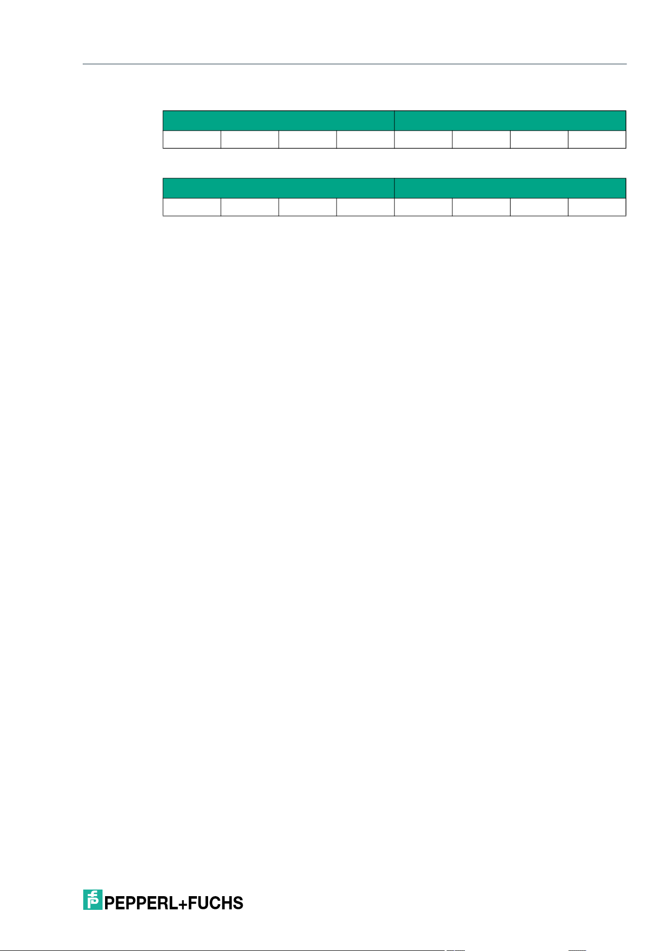
IQT3 / IQT4 Series
ExpertMode
2026-05
129
Normal orientation, DS = 16#00
Reverse orientation, DS = 16#01
Tag Lost Smoothing (E5)
The E5 parameter sets the number of unsuccessful write/read attempts when executing an
Enhanced command before the device outputs the telegram with the status value 16#05. Via
the telegram with the status 16#05 the device indicates that a tag has left the sensing range or
could no longer be identified.
This parameter is only used when performing enhanced commands. When executing single
commands, the parameter has no significance.
The value for the E5 parameter can be increased if communication between the tag and the
device is unstable. This reduces the number of telegrams with status 16#05 received. In
dynamic applications, this parameter can be used to bridge gaps in the sensing range without
receiving a status 16#05 message if there are minor interruptions in the tag communication.
The sensing zone appears more homogeneous.
If a large number of tags are detected at the same time during a dynamic application, receipt of
the telegram with status 16#05 can be delayed by increasing the parameter value of E5. This
allows the status 16#00 telegrams with the read-in information of the tags to be transmitted first.
The status 16#05 telegrams are transmitted with a time delay.
Reducing the E5 parameter value shortens the reaction time of the system when a tag leaves
the sensing range. The status 16#05 telegrams are sent quicker.
The transmission of the following telegrams is not affected by the E5 parameter setting and
they are transmitted immediately:
• Status 16#00: Execution successful; data read or written
Information Frame Mode (IF)
The IF parameter is set to 16#01 by default and cannot be changed. It signals that additional
information about the RSSI value of the reading is output for each read access to a tag.
Data block 0 Data block 1
Byte 0 Byte 1 Byte 2 Byte 3 Byte 0 Byte 1 Byte 2 Byte 2
Data block 0 Data block 1
Byte 3 Byte 2 Byte 1 Byte 0 Byte 3 Byte 2 Byte 1 Byte 0
Parameter abbreviation: E5 (16#4535)
Parameter length: 1 byte
Default: 16#05
= 5 unsuccessful read/write attempts
Value range: 16#00 ... 16#0A
= 0 ... 10 unsuccessful read/write attempts
Parameter abbre-
viation:
IF
Parameter length: 1 byte
Default: 16#01
Value range: 16#01
2026-05
130
IQT3 / IQT4 Series
ExpertMode
LED Masking (LM)
The LM parameter can be used to set which operating status should be displayed via the LEDs
of the RFID read/write device.
Noise Detection Level (ND)
The ND parameter sets the threshold value (0–100 %) from which the status message LED is
activated by reducing the read/write range (e.g., due to detuning).
For example, if the value is set to 50 dec, the LED lights up as soon as the read/write distance
of the device drops by 50 % compared to the ideal value.
Number of Tags to Find (NT)
The NT parameter specifies the number of tags that the device searches for within the sensing
range. Each command is repeated according to the Number of Attempts (TA) parameter. If the
number of tags found during the repeat operations reaches or exceeds the NT value, all further
runs are canceled. The command is canceled, and the data is output.
If the number of tags is set to 255 (= 16#FF), the function is deactivated. This parameter only
affects single commands. It does not affect enhanced commands.
Parameter abbre-
viation:
LM
Parameter length: 2 bytes
Default: 16#0000
Value range
1
:
1.Binary combinations are possible
16#0000 = All operating statuses are output via LED
16#0001 = Operating status "Fault due to external signals in the useful
spectrum" is suppressed
16#0002 = Operating status "Detuning due to surrounding metal" is sup-
pressed
16#0004 = Operating status "Excess temperature warning" is suppressed
Note
The operating statuses "Excess temperature error" (ST = 16#0008) and
"Undervoltage/overvoltage error" (ST = 16#0010) cannot be suppressed.
The operating status of the RFID read/write device can still be read at any time via the ST
parameter.
Parameter abbre-
viation:
ND
Parameter length: 1 byte
Default: 16#32 (50
dec
)
Value range: 16#00 … 16#64 (0
de
... 100
dec
)
Parameter abbre-
viation:
NT (16#4E54)
Parameter length: 1 byte
Default: 16#FF
Value range: 16#01 … 16#14; 16#FF

IQT3 / IQT4 Series
ExpertMode
2026-05
131
Operating Hours (OH)
The OH parameter outputs the information about how long the read/write device is in operation
and how long a read/write command is running.
The operating time of the read/write device is 83
dec
hours (16#00000053). The duration of the
read/write commands is 3
dec
hours (16#00000003).
Transmission Power (PT)
The PT parameter can be used to set the transmitter radiated power of the read/write device.
The transmitter radiated power affects the detection range of a tag's sensing zone. Increasing
the transmitter radiated power extends the detection range for read and write access to a tag.
A transmitter radiated power level of PT1 is preset in the factory setting. It is possible to set up
to 4 power levels (PT1 … PT4) in the device. This enables a ramp to be generated for a contin-
uous increase in the transmitter radiated power. When used in conjunction with a "Single Read"
or "Single Write" command and the definition of the cancellation criterion (NT parameter), the
read or write operation is canceled as soon as the set number of tags is detected.
Setting multiple transmitter radiated power levels increases the execution time of a read or write
operation. This is due to the inventory runs that are executed for each power level. The NT can-
cellation criterion can be set to reduce the execution time.
By reducing the transmitter radiated power, the device can be operated permanently at higher
ambient temperatures. The self-heating of the device is reduced. If the device is operated in
continuous operation with "enhanced" read/write commands with maximum transmitter radi-
ated power, the ambient temperature must not exceed 55 °C. In Eco mode, the ambient tem-
perature can be increased to a maximum of 70 °C. In addition to setting the transmitter radiated
power, the read/write device has additional protection mechanisms that prevent the device
from overheating.
Parameter abbre-
viation:
OH(16#4F48)
Parameter length: 8 bytes
• Byte 1–4: Read/write device operating time in hours
1
• Byte 5–8: Operating time read/write commands in hours
2
1.IO-Link communication active
2.Read/write command active
Parameter abbreviation: PT (16#5054)
Parameter length: 1 byte
Default: IQT3: 16#0004;
IQT4: 16#0001
Value range: 16#0001 (Min)
16#0002 (Eco)
16#0003 (Normal)
16#0004 (Maximum)
Note
By reducing the transmitter radiated power, the RFID read/write device can be operated in
continuous operation at a higher ambient temperature (for more information, see Chapter 5.6
Ambient temperature range).see "Overtemperature Handling (TO)" on page 136.

2026-05
132
IQT3 / IQT4 Series
ExpertMode
Reply Frame Mode (QV)
The QV parameter is set to 16#4D by default and cannot be changed. It signals that the multi-
frame protocol is activated. This causes every tag that has responded to be output.
Q-Value (QW)
The QW parameter defines the number of tags expected in the sensing range. This setting
affects the time slot when communicating with a tag to avoid collisions due to simultaneous
communication between multiple tags.
The Q value influences the execution time of write/read commands. Reducing the Q value
shortens the execution time for accessing tags.
Reset to Default (RD)
The RD parameter resets the device to the factory setting. The RD parameter is written in the
process. Read access to this parameter is not possible.
RSSI Lower Limit (RL)
The RL parameter can be used to set the lower RSSI threshold value. As soon as the RSSI
value of a read tag falls below the set threshold value, it is no longer output.
Parameter abbre-
viation:
QV
Parameter length: 1 byte
Default: 16#4D
Value range: 16#4D
Parameter abbre-
viation:
QW (16#5157)
Parameter length: 1 byte
Default: 16#00
Value range: 16#00 = one tag
16#01 = two tags
16#02 = multiple tags (approx. 4)
16#03 = many tags (approx. 8)
16#04 = very many tags (approx. 16)
Parameter abbre-
viation:
RD (16#5244)
Table 8.13
Parameter abbre-
viation:
RL
Parameter length: 1 byte
Default: 16#00
Value range: 16#00 … 16#64 (0
de
... 100
dec
)
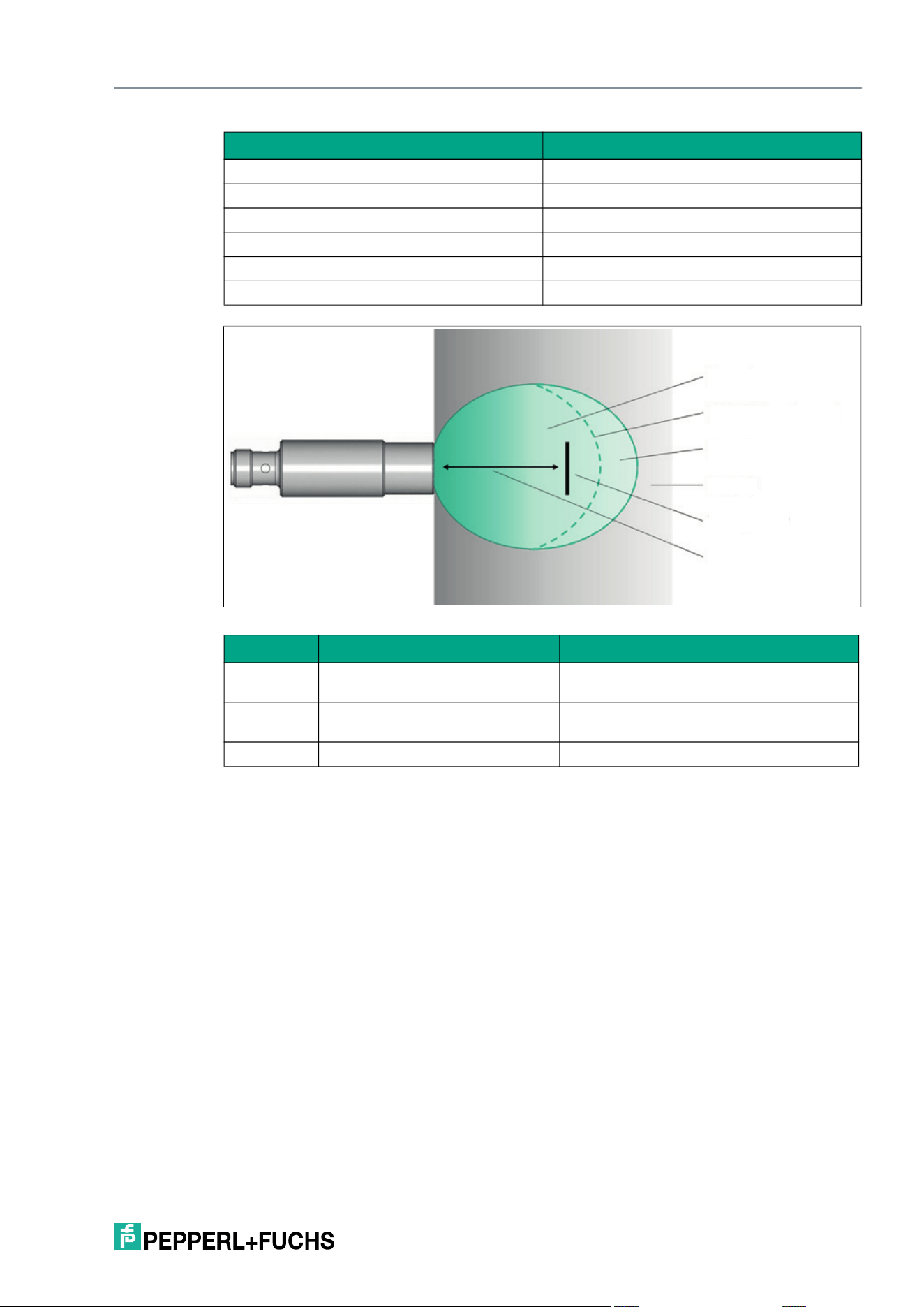
IQT3 / IQT4 Series
ExpertMode
2026-05
133
Figure 8.1 Schematic representation of the read range of the IQT4-18GM-IO-V1, based on RSSI
RSSI Upper Limit (RU)
The RL parameter can be used to set the upper RSSI threshold value. As soon as the RSSI
value of a read tag exceeds the set threshold value, it is no longer output.
Legend Designation
1 Zone A
2 RSSI threshold value
3 Zone B
4 Zone C
5 Tag
6 Read/write distance
Zone RSSI Note
A RSSI tag RSSI threshold value The tag is in the sensing range and is out-
put.
B RSSI tag < RSSI threshold value The tag is within the maximum sensing
range, but is not output.
C - The tag is outside the sensing range.
Parameter abbre-
viation:
RU
Parameter length: 1 byte
Default: 16#64
Value range: 16#00 … 16#64 (0
de
... 100
dec
)
1
2
3
4
5
6
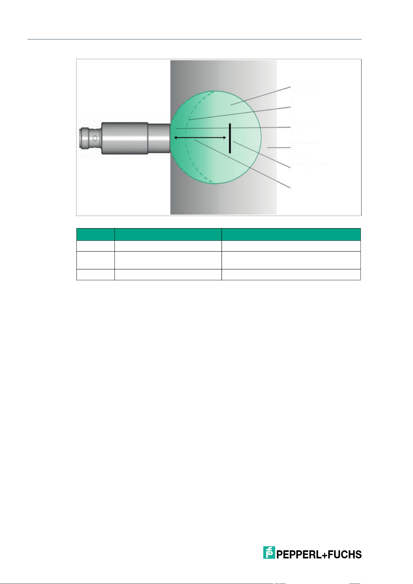
2026-05
134
IQT3 / IQT4 Series
ExpertMode
Figure 8.2 Schematic representation of the read range of the IQT4-18GM-IO-V1, based on RSSI
Frontend State (ST)
The ST parameter reads the operating status of the read/write device.
Application Specific Tag (T2)
The T2 parameter can be used to mark the device with an application identifier to store applica-
tion-specific information on the device.
Zone RSSI Note
A RSSI tag RSSI threshold value The tag is in the sensing range and is output.
B RSSI tag > RSSI threshold value The tag is in the sensing range but is not out-
put.
C - The tag is outside the sensing range.
Parameter abbre-
viation:
ST (16#5354)
Parameter length: Byte 1: current status
Byte 2: status saved since the last read
Value range: 16#01 = Fault
16#02 = Detuning due to surrounding metal
16#04 = Excess temperature warning, internal temperature between
80–85 °C.
16#08 = Excess temperature error, internal temperature > 85 °C.
16#10 = Under/overvoltage error, voltage < 17.5 V DC or > 30.5 V DC
Parameter abbre-
viation:
T2
Parameter length: max. 32 bytes
Default: Your automation, our passion.
1
2
3
4
5
6

IQT3 / IQT4 Series
ExpertMode
2026-05
135
Function Tag (T3)
The T3 parameter can be used to mark the device with a function tag to store function-specific
information on the device.
Location Tag (T4)
The T4 parameter can be used to mark the device with a location tag to store location-specific
information on the device.
Installation Tag (T5)
The T5 parameter can be used to mark the device with an installation identifier to store installa-
tion-specific information (e.g., date or data of the initial commissioning) on the device.
Tries Allowed (TA)
The Tries Allowed (TA) parameter sets the number of access attempts during execution of a
read/write operation on a tag.
This parameter affects the execution time of write and read commands. If the Tries Allowed
parameter value is increased, the execution time for a command increases, because more
access attempts are made.
By increasing the parameter value, the reliability for writing and reading tag data can be
increased if communication between the device and the tag is unstable.
To limit the increase in execution time caused by increasing tries allowed, it is recommended to
parameterize the NT cancellation criterion. This will stop the command execution as soon as
the set number of tags has been identified.
Temperature (TE)
The TE parameter indicates the internal temperature of the read/write device.
Parameter abbreviation: T3
Parameter length: max. 32 bytes
Default: ***
Parameter abbreviation: T4
Parameter length: max. 32 bytes
Default: ***
Parameter abbreviation: T5
Parameter length: max. 32 bytes
Default: ***
Parameter abbreviation: TA (16#5441)
Parameter length: 1 byte
Default: 16#02 2 access attempts
Value range: 16#01 … 16#0A
Parameter abbre-
viation:
TE (16#5445)
Parameter length: 2 bytes
• Byte 1: Temperature on the power amplifier
• Byte 2: Temperature on the microcontroller

2026-05
136
IQT3 / IQT4 Series
ExpertMode
Tag ID Filter (TI)
The TI parameter sets a filter to the UID of a tag. The read/write commands are therefore only
executed for tags with the UID that corresponds to the set filter. The filter can be set to the entire
UID (8 bytes) or the leading bytes.
Overtemperature Handling (TO)
The TO parameter defines the behavior of the read/write device in the event of excess tempera-
ture. Setting the parameter can protect the device against overheating.
Voltages (VO)
The VO parameter can be used to read the input voltage and other internal voltage and current
values.
Parameter abbre-
viation:
TI (16#5449)
Value range: 0 ... 8-byte UID
Note
The TI parameter is stored in the volatile memory.
Parameter abbreviation: TO (16#544F)
Parameter length: 1 byte
Default: 16#00
Value range: 16#00 = Switch off
16#01 = Reduce power
16#02 = Reduce duty cycle
Value Mode Function
0 Switch off The device switches off automatically if an internal temperature >
85 °C is measured.
If the internal temperature falls below 80 °C, the device switches on
automatically.
1 Reduce power The device automatically reduces the transmitter radiated power
when an internal temperature is measured between 80–85 °C.
The device switches off automatically if an internal temperature >
85 °C is measured.
2 Reduce duty
cycle
The device pauses for 0.5 ms–1 s after a transmission cycle when
the internal temperature is measured between 80–85 °C.
The length of the pause time depends on the internal temperature
and the duration of the last read/write command.
The device switches off automatically if an internal temperature >
85 °C is measured.
Note
Note that in "Reduce duty cycle" mode, the read/write device does not identify any tags during
the pause time.
Consider this pause for applications with tags that move dynamically through the sensing
range. If necessary, use a different protection mechanism.
Parameter abbreviation: VO
Parameter length: 14 bytes
IQT3 / IQT4 Series
ExpertMode
2026-05
137
8.6.3.4 Parameter Examples
Read Parameter
Command telegram
Byte Content
Example
parame-
ter AF
Example
parame-
ter CT
Example
parame-
ter DN
Example
parame-
ter DR
Example
parame-
ter DS
Example
parame-
ter E5
Example
parame-
ter IF
Example
parame-
ter LM
Example
parame-
ter ND
Example
parame-
ter NT
Example
parame-
ter OH
Example
parame-
ter PT
Example
parame-
ter QV
0 Control
byte /
frame
length
16#x0 16#x0 16#x0 16#x0 16#x0 16#x0 16#x0 16#x0 16#x0 16#x0 16#x0 16#x0 16#x0
1 Frame
length
16#0B 16#0B 16#0B 16#0B 16#0B 16#0B 16#0B 16#0B 16#0B 16#0B 16#0B 16#0B 16#0B
2 Fragmen-
tation
counter
16#00 16#00 16#00 16#00 16#00 16#00 16#00 16#00 16#00 16#00 16#00 16#00 16#00
3 Telegram
length
(high byte)
16#00 16#00 16#00 16#00 16#00 16#00 16#00 16#00 16#00 16#00 16#00 16#00 16#00
4 Telegram
length
(low byte)
16#08 16#08 16#08 16#08 16#08 16#08 16#08 16#08 16#08 16#08 16#08 16#08 16#08
5 Command 16#BE 16#BE 16#BE 16#BE 16#BE 16#BE 16#BE 16#BE 16#BE 16#BE 16#BE 16#BE 16#BE
6 System
Code
16#51 "Q" 16#51 "Q" 16#51 "Q" 16#51 "Q" 16#51 "Q" 16#51 "Q" 16#51 "Q" 16#51 "Q" 16#51 "Q" 16#51 "Q" 16#51 "Q" 16#51 "Q" 16#51 "Q"
7 Parame-
ter name
(high byte)
16#41 "A" 16#43 "C" 16#44 "D" 16#44 "D" 16#44 "D" 16#45 "E" 16#49 "I" 16#4C "L" 16#4E "N" 16#4E "N" 16#4F "O" 16#50 "P" 16#51 "Q"
8 Parame-
ter name
(low byte)
16#46 "F" 16#54 "T" 16#4E "N" 16#52 "R" 16#53 "S" 16#35 "5" 16#46 "F" 16#4D "M" 16#44 "D" 16#54 "T" 16#48 "H" 16#54 "T" 16#56 "V"
9 Length
parame-
ter (high
byte)
16#00 16#00 16#00 16#00 16#00 16#00 16#00 16#00 16#00 16#00 16#00 16#00 16#00
10 Length
parame-
ter (low
byte)
16#00 16#00 16#00 16#00 16#00 16#00 16#00 16#00 16#00 16#00 16#00 16#00 16#00
11 Com-
mand
parameter
12 Com-
mand
parameter
13 Com-
mand
parameter
...
31 Com-
mand
parameter
Byte Content
Example
parame-
ter QW
Example
parame-
ter RL
Example
parame-
ter RU
Example
parame-
ter ST
Example
parame-
ter T2
Example
parame-
ter T3
Example
parame-
ter T4
Example
parame-
ter T5
Example
parame-
ter TA
Example
parame-
ter TE
Example
parame-
ter TI
Example
parame-
ter TO
Example
parame-
ter VO
0 Control
byte /
frame
length
16#x0 16#x0 16#x0 16#x0 16#x0 16#x0 16#x0 16#x0 16#x0 16#x0 16#x0 16#x0 16#x0
1 Frame
length
16#0B 16#0B 16#0B 16#0B 16#0B 16#0B 16#0B 16#0B 16#0B 16#0B 16#0B 16#0B 16#0B
2 Fragmen-
tation
counter
16#00 16#00 16#00 16#00 16#00 16#00 16#00 16#00 16#00 16#00 16#00 16#00 16#00
3 Telegram
length
(high
byte)
16#00 16#00 16#00 16#00 16#00 16#00 16#00 16#00 16#00 16#00 16#00 16#00 16#00
4 Telegram
length
(low byte)
16#08 16#08 16#08 16#08 16#08 16#08 16#08 16#08 16#08 16#08 16#08 16#08 16#08
5 Com-
mand
16#BE 16#BE 16#BE 16#BE 16#BE 16#BE 16#BE 16#BE 16#BE 16#BE 16#BE 16#BE 16#BE
6 System
code
16#51 "Q" 16#51 "Q" 16#51 "Q" 16#51 "Q" 16#51 "Q" 16#51 "Q" 16#51 "Q" 16#51 "Q" 16#51 "Q" 16#51 "Q" 16#51 "Q" 16#51 "Q" 16#51 "Q"
7 Parame-
ter name
(high
byte)
16#51 "Q" 16#52 "R" 16#52 "R" 16#53 "S" 16#54 "T" 16#54 "T" 16#54 "T" 16#54 "T" 16#54 "T" 16#54 "T" 16#54 "T" 16#54 "T" 16#56 "V"
2026-05
138
IQT3 / IQT4 Series
ExpertMode
Response telegram—status 16#00
8 Parame-
ter name
(low byte)
16#57 "W" 16#4C "L" 16#55 "U" 16#54 "T" 16#32 "2" 16#33 "3" 16#34 "4" 16#35 "5" 16#41 "A" 16#45 "E" 16#49 "I" 16#4F "O" 16#4F
"O"
9 Length
parame-
ter (high
byte)
16#00 16#00 16#00 16#00 16#00 16#00 16#00 16#00 16#00 16#00 16#00 16#00 16#00
10 Length
parame-
ter (low
byte)
16#00 16#00 16#00 16#00 16#00 16#00 16#00 16#00 16#00 16#00 16#00 16#00 16#00
11 Com-
mand
parame-
ter
12 Com-
mand
parame-
ter
13 Com-
mand
parame-
ter
...
31 Com-
mand
parame-
ter
Byte Content
Example
parame-
ter QW
Example
parame-
ter RL
Example
parame-
ter RU
Example
parame-
ter ST
Example
parame-
ter T2
Example
parame-
ter T3
Example
parame-
ter T4
Example
parame-
ter T5
Example
parame-
ter TA
Example
parame-
ter TE
Example
parame-
ter TI
Example
parame-
ter TO
Example
parame-
ter VO
Byte Content
Example
parame-
ter AF
Example
parame-
ter CT
Example
parame-
ter DN
Example
parame-
ter DR
Example
parame-
ter DS
Example
parame-
ter E5
Example
parame-
ter IF
Example
parame-
ter LM
Example
parame-
ter ND
Example
parame-
ter NT
Example
parame-
ter OH
Example
parame-
ter PT
Example
parame-
ter QV
0 Control
byte /
frame
length
16#00 16#x0 16#00 16#00 16#00 16#00 16#00 16#00 16#00 16#x0 16#00 16#x0 16#x0
1 Frame
length
16#08 16#08 16#15 16#08 16#08 16#08 16#08 16#09 16#08 16#08 16#0F 16#09 16#08
2 Fragmen-
tation
counter
16#00 16#00 16#00 16#00 16#00 16#00 16#00 16#00 16#00 16#00 16#00 16#00 16#00
3 Telegram
length
(high byte)
16#00 16#00 16#00 16#00 16#00 16#00 16#00 16#00 16#00 16#00 16#00 16#00 16#00
4 Telegram
length
(low byte)
16#05 16#05 16#12 16#05 16#05 16#05 16#05 16#06 16#05 16#05 16#0C 16#06 16#05
5 Command 16#BE 16#BE 16#BE 16#BE 16#BE 16#BE 16#BE 16#BE 16#BE 16#BE 16#BE 16#BE 16#BE
6 Status 16#00 16#00 16#00 16#00 16#00 16#00 16#00 16#00 16#00 16#00 16#00 16#00 16#00
7 Data 16#00 16#14 16#34 16#00 16#01 16#05 16#01 16#00 16#32 16#FF 16#00 16#00 16#4D
8 Data 16#30 16#03 16#00 16#04
9 Data 16#30 16#00
10 Data 16#30 16#11
11 Data 16#30 16#00
12 Data 16#31 16#00
13 Data 16#38 16#00
14 Data 16#30 16#03
15 Data 16#36
16 Data 16#38
17 Data 16#34
18 Data 16#34
19 Data 16#37
20 Data 16#30
...
31 Data
IQT3 / IQT4 Series
ExpertMode
2026-05
139
Byte Content
Example
parame-
ter QW
Example
parame-
ter RL
Example
parame-
ter RU
Example
parame-
ter ST
Example
parame-
ter T2
Example
parame-
ter T3
Example
parame-
ter T4
Example
parame-
ter T5
Example
parame-
ter TA
Example
parame-
ter TE
Example
parame-
ter TI
Example
parame-
ter TO
Exam-
ple
parame-
ter VO
0 Control
byte /
frame
length
16#x0 16#x0 # 16#00 16#00 16#00 16#00 16#00 16#x0 16#x0 16#x0 16#x0 16#00
1 Frame
length
16#08 16#08 16#08 16#09 16#0a 16#0a 16#0a 16#0a 16#08 16#08 16#0B 16#08 16#15
2 Fragmen-
tation
counter
16#00 16#00 16#00 16#00 16#00 16#00 16#00 16#00 16#00 16#00 16#00 16#00 16#00
3 Telegram
length
(high byte)
16#00 16#00 16#00 16#00 16#00 16#00 16#00 16#00 16#00 16#00 16#00 16#00 16#00
4 Telegram
length
(low byte)
16#05 16#05 16#05 16#06 16#07 16#07 16#07 16#07 16#05 16#05 16#08 16#05 16#12
5 Command 16#BE 16#BE 16#BE 16#BE 16#BE 16#BE 16#BE 16#BE 16#BE 16#BE 16#BE 16#BE 16#BE
6 Status 16#00 16#00 16#00 16#00 16#00 16#00 16#00 16#00 16#00 16#00 16#00 16#00 16#00
7 Data 16#00 16#00 16#50 16#00 16#2a 16#2a 16#2a 16#2a 16#02 16#20 16#E0 16#02 16#5D
8 Data 16#00 16#2a 16#2a 16#2a 16#2a 16#08 16#15
9 Data 16#2a 16#2a 16#2a 16#2a 16#01 16#14
10 Data 16#48 16#71
11 Data 16#0C
12 Data 16#DF
13 Data 16#85
14 Data 16#E8
15 Data 16#0C
16 Data 16#B9
17 Data 16#00
18 Data 16#00
19 Data 16#02
20 Data 16#96
...
31 Data
Example
Example parameter AF (16#00 = all tags respond)
Example parameter CT (16#14 = tag type 20)
Example parameter DN (Serial number 40000180684470)
Example parameter DR 16#00 = normal = 26 kilobit/s
Example parameter DS (16#01 = byte-by-byte exchange of blocks)
Example parameter E5 (16#05 = 5 unsuccessful read/write attempts
Example parameter IF (16#01 = Information Frame Mode activated)
Example parameter LM (16#0003 = "Fault due to external signals" and "Detuning
due to surrounding metal" is suppressed)
Example parameter ND (16#32 = status display from 50% range reduction)
Example parameter NT (16#FF = Off)
Example parameter OH (16#0000001100000003 = 17 hours operating time & 3
hours of active read/write commands)
Example parameter PT (16#04 = Maximum)
Example parameter QV (16#4D = multi-frame protocol)
Example parameter QW (16#00 = one tag)
Example parameter RL (16#00 = lower RSSI threshold of 0)
Example parameter RU (16#50 = upper RSSI threshold value of 80
dec
2026-05
140
IQT3 / IQT4 Series
ExpertMode
Example parameter ST (16#0000 = no fault)
Example parameter T2 (***)
Example parameter T3 (***)
Example parameter T4 (***)
Example parameter T5 (***)
Example parameter TA (16#02 = 2 access attempts)
Example parameter TE (IQT4: 16#20 = 32° at the microcontroller)
Example parameter TI (Filter on UID, starting with 16#E0080148)
Example parameter TO (16#02 = Duty Cycle)
Example parameter VO (16#5D15 = 23829 mV input voltage;
16#14710CDF85E80CB900000296 = other internal volt-
age and current values)
Example
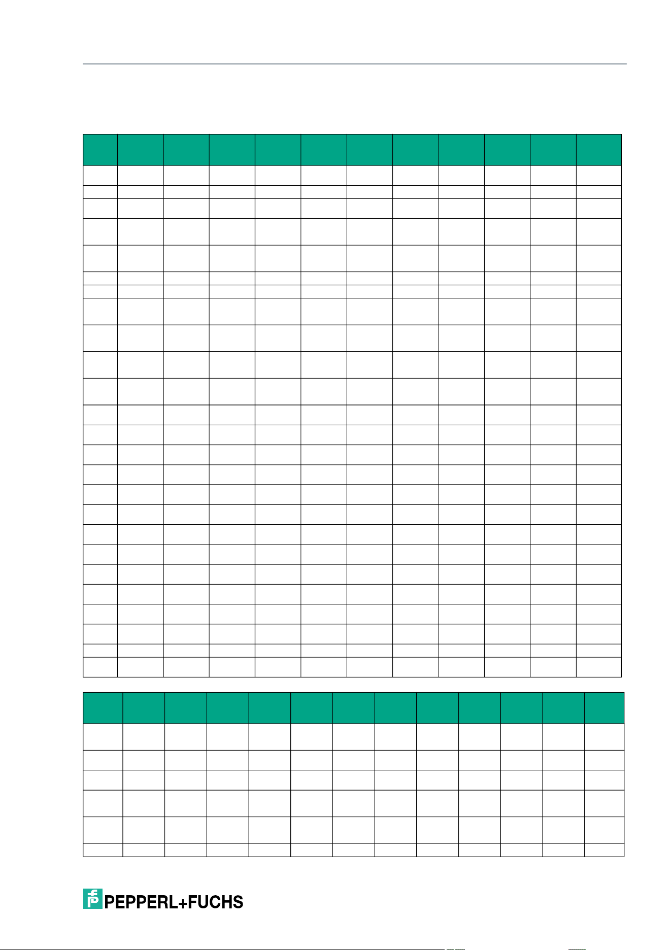
IQT3 / IQT4 Series
ExpertMode
2026-05
141
Write Parameter
Command telegram
Byte Content
Example
parameter
AF
Example
parameter
BB
Example
parameter
CT
Example
parameter
DR
Example
parameter
DS
Example
parameter
E5
Example
parameter
LM
Example
parameter
ND
Example
parameter
NT
Example
parameter
PT
0 Control byte /
frame length
16#x0 16#x0 16#x0 16#x0 16#x0 16#x0 16#x0 16#x0 16#x0 16#x0
1 Frame length 16#0C 16#0B 16#0C 16#0C 16#0C 16#0C 16#0D 16#0C 16#0C 16#0D
2 Fragmenta-
tion counter
16#00 16#00 16#00 16#00 16#00 16#00 16#00 16#00 16#00 16#00
3 Telegram
length (high
byte)
16#00 16#00 16#00 16#00 16#00 16#00 16#00 16#00 16#00 16#00
4 Telegram
length (low
byte)
16#09 16#08 16#09 16#09 16#09 16#09 16#0A 16#09 16#09 16#0A
5 Command 16#BF 16#BF 16#BF 16#BF 16#BF 16#BF 16#BF 16#BF 16#BF 16#BF
6 System code 16#51 "Q" 16#51 "Q" 16#51 "Q" 16#51 "Q" 16#51 "Q" 16#51 "Q" 16#51 "Q" 16#51 "Q" 16#51 "Q" 16#51 "Q"
7 Parameter
name (high
byte)
16#41 "A" 16#42 "B" 16#43 "C" 16#44 "D" 16#44 "D" 16#45 "E" 16#4C "L" 16#4E "N" 16#4E "N" 16#50 "P"
8 Parameter
name (low
byte)
16#46 "F" 16#42 "B" 16#54 "T" 16#52 "R" 16#53 "S" 16#35 "5" 16#4D "M" 16#44 "D" 16#54 "T" 16#54 "T"
9 Length
parameter
(high byte)
16#00 16#00 16#00 16#00 16#00 16#00 16#00 16#00 16#00 16#00
10 Length
parameter
(low byte)
16#01 16#00 16#01 16#01 16#01 16#01 16#02 16#01 16#01 16#02
11 Command
parameter
16#39 16#15 16#01 16#00 16#05 16#00 16#32 16#FF 16#00
12 Command
parameter
16#01 16#01
13 Command
parameter
14 Command
parameter
15 Command
parameter
16 Command
parameter
17 Command
parameter
18 Command
parameter
19 Command
parameter
20 Command
parameter
21 Command
parameter
22 Command
parameter
...
31 Command
parameter
Byte Content
Example
parameter
QW
Example
parameter
RD
Example
parameter
RL
Example
parameter
RU
Example
parameter
T2
Example
parameter
T3
Example
parameter
T4
Example
parameter
T5
Example
parameter
TA
Example
parameter
TI
Example
parameter
TO
0 Control byte
/ frame
length
16#x0 16#x0 16#x0 16#x0 16#x0 16#x0 16#x0 16#x0 16#x0 16#x0 16#x0
1 Frame
length
16#0C 16#0B 16#0C 16#0C 16#16 16#13 16#13 16#14 16#0C 16#0F 16#0C
2 Fragmenta-
tion counter
16#00 16#00 16#00 16#00 16#00 16#00 16#00 16#00 16#00 16#00 16#00
3 Telegram
length (high
byte)
16#00 16#00 16#00 16#00 16#00 16#00 16#00 16#00 16#00 16#00 16#00
4 Telegram
length (low
byte)
16#09 16#08 16#09 16#09 16#13 16#10 16#10 16#11 16#09 16#0C 16#09
5 Command 16#BF 16#BF 16#BF 16#BF 16#BF 16#BF 16#BF 16#BF 16#BF 16#BF 16#BF
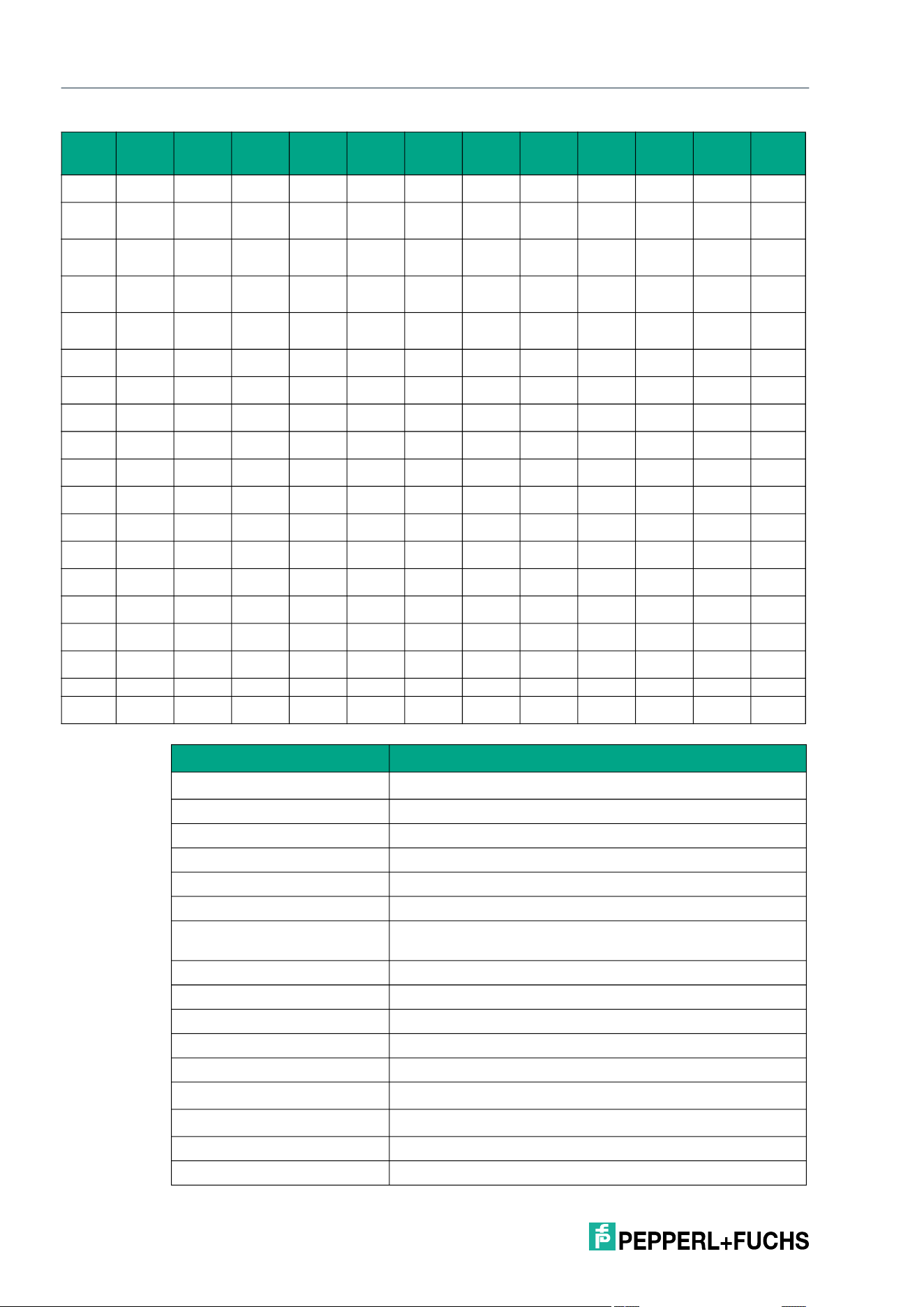
2026-05
142
IQT3 / IQT4 Series
ExpertMode
6 System
code
16#51 "Q" 16#51 "Q" 16#51 "Q" 16#51 "Q" 16#51 "Q" 16#51 "Q" 16#51 "Q" 16#51 "Q" 16#51 "Q" 16#51 "Q" 16#51 "Q"
7 Parameter
name (high
byte)
16#51 "Q" 16#52 "R" 16#52 "R" 16#52 "R" 16#54 "T" 16#54 "T" 16#54 "T" 16#54 "T" 16#54 "T" 16#54 "T" 16#54 "T"
8 Parameter
name (low
byte)
16#57 "W" 16#44 "D" 16#55 "L" 16#4C "U" 16#32 "2" 16#33 "3" 16#34 "4" 16#35 "5" 16#41 "A" 16#49 "I" 16#4F "O"
9 Length
parameter
(high byte)
16#00 16#00 16#00 16#00 16#00 16#00 16#00 16#00 16#00 16#00 16#00
10 Length
parameter
(low byte)
16#01 16#00 16#01 16#01 16#0B 16#08 16#08 16#09 16#01 16#04 16#01
11 Command
parameter
16#04 16#14 16#50 16#41 16#46 16#4C 16#49 16#02 16#E0 16#02
12 Command
parameter
16#70 16#75 16#6F 16#6E 16#08
13 Command
parameter
16#70 16#6E 16#63 16#73 16#01
14 Command
parameter
16#6C 16#63 16#61 16#74 16#48
15 Command
parameter
16#69 16#74 16#74 16#61
16 Command
parameter
16#63 16#69 16#69 16#6C
17 Command
parameter
16#61 16#6F 16#6F 16#6C
18 Command
parameter
16#74 16#6E 16#6E 16#61
19 Command
parameter
16#69 16#74
20 Command
parameter
16#6F 16#69
21 Command
parameter
16#6E 16#6F
22 Command
parameter
16#6E
...
31 Command
parameter
Byte Content
Example
parameter
QW
Example
parameter
RD
Example
parameter
RL
Example
parameter
RU
Example
parameter
T2
Example
parameter
T3
Example
parameter
T4
Example
parameter
T5
Example
parameter
TA
Example
parameter
TI
Example
parameter
TO
Example
Example parameter AF (16#39 = 57
dec
)
Example parameter BB
Example parameter CT (16#15 = tag type 21)
Example parameter DR (16#01 = fast read mode)
Example parameter DS (16#00 = no data exchange)
Example parameter E5 (16#05 = 5 attempts up to status 5)
Example parameter LM (16#0001 = operating status "Fault due to external signals in
the useful spectrum" is suppressed)
Example parameter ND (16#32 = threshold value 50%)
Example parameter NT (16#FF = "Off")
Example parameter PT (16#0001 = "Min")
Example parameter QW (16#04 = "very many tags")
Example parameter RD
Example parameter RL (16#14 = lower RSSI threshold value 20
dec
)
Example parameter RU (16#50 = upper RSSI threshold value 80
dec
)
Example parameter T2 ("Application")
Example parameter T3 ("Function")
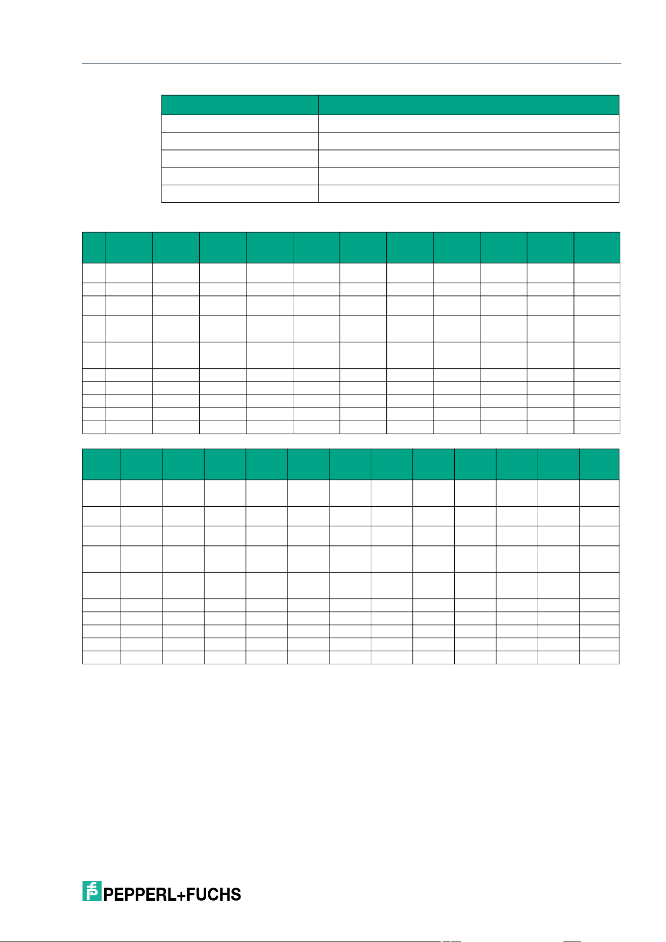
IQT3 / IQT4 Series
ExpertMode
2026-05
143
Response telegram—status 16#00
Example parameter T4 ("Location")
Example parameter T5 ("Installation")
Example parameter TA (16#02 = 2 attempts)
Example parameter TI (16#E0080148 = UID starting with .E0.08.01.48
Example parameter TO (16#02 = "Reduce Duty Cycle")
Example
Byte Content
Example
parameter
AF
Example
parameter
BB
Example
parameter
CT
Example
parameter
DR
Example
parameter
DS
Example
parameter
E5
Example
parameter
LM
Example
parameter
ND
Example
parameter
NT
Example
parameter
PT
0 Control byte /
frame length
16#00 16#00 16#00 16#00 16#00 16#00 16#00 16#00 16#00 16#00
1 Frame length 16#07 16#07 16#07 16#07 16#07 16#07 16#07 16#07 16#07 16#07
2 Fragmenta-
tion counter
16#00 16#00 16#00 16#00 16#00 16#00 16#00 16#00 16#00 16#00
3 Telegram
length (high
byte)
16#00 16#00 16#00 16#00 16#00 16#00 16#00 16#00 16#00 16#00
4 Telegram
length (low
byte)
16#04 16#04 16#04 16#04 16#04 16#04 16#04 16#04 16#04 16#04
5 Command 16#BF 16#BF 16#BF 16#BF 16#BF 16#BF 16#BF 16#BF 16#BF 16#BF
6 Status 16#00 16#00 16#00 16#00 16#00 16#00 16#00 16#00 16#00 16#00
7 Data
...
31 Data
Byte Content
Example
parameter
QW
Example
parameter
RD
Example
parameter
RL
Example
parameter
RU
Example
parameter
T2
Example
parameter
T3
Example
parameter
T4
Example
parameter
T5
Example
parameter
TA
Example
parameter
TI
Example
parameter
TO
0 Control byte
/ frame
length
16#00 16#00 16#00 16#00 16#00 16#00 16#00 16#00 16#00 16#00 16#00
1 Frame
length
16#07 16#07 16#07 16#07 16#07 16#07 16#07 16#07 16#07 16#07 16#07
2 Fragmenta-
tion counter
16#00 16#00 16#00 16#00 16#00 16#00 16#00 16#00 16#00 16#00 16#00
3 Telegram
length (high
byte)
16#00 16#00 16#00 16#00 16#00 16#00 16#00 16#00 16#00 16#00 16#00
4 Telegram
length (low
byte)
16#04 16#04 16#04 16#04 16#04 16#04 16#04 16#04 16#04 16#04 16#04
5 Command 16#BF 16#BF 16#BF 16#BF 16#BF 16#BF 16#BF 16#BF 16#BF 16#BF 16#BF
6 Status 16#00 16#00 16#00 16#00 16#00 16#00 16#00 16#00 16#00 16#00 16#00
7 Data
...
31 Data
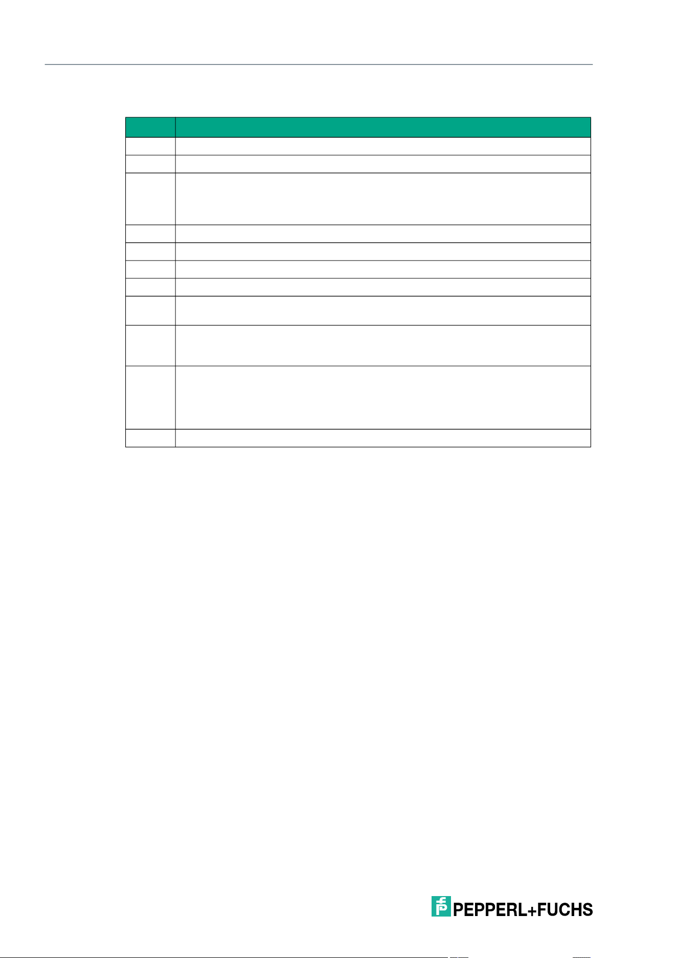
2026-05
144
IQT3 / IQT4 Series
ExpertMode
8.7 Error / Status Messages
Status Meaning
16#00
The command was executed successfully.
16#01
Excess temperature
16#04
Parameter error
If this status message is received immediately after the command is sent, a param-
eter within the command is outside the value range or the telegram structure is
incorrect.
16#05
The tag has left the sensing zone.
16#06
Hardware error, e.g., error on self test or faulty device.
16#07
Internal device fault
16#09
The programmed tag type is not compatible with the connected read/write device.
16#0A
Short-form data format: multiple tags in the sensing range.
Long-form data format: multiple tags in the sensing range with the same UID.
16#0B
Telegram with additional information
This additional information (e.g., RSSI value) is transmitted in a telegram with this
status.
16#0E
Buffer overflow
The size of the internal telegram buffer has been exceeded. The device has gener-
ated telegrams faster than they could be transmitted to the controller. The telegram
buffer is cleared by inverting the Delete bit. In addition, the function of the hand-
shake procedure must be checked.
16#0F
Indicates the end of an output in the long-form data format.
2026-05
152
IQT3 / IQT4 Series
Appendix
9 Appendix
9.1 Troubleshooting
Index Description Solution
1 No blue LED on; only the green LED
flashes
Is the auto-start function active?
2 No orange LED if read/write tag is
within the sensing range
Is the correct tag type set? Read the IO-Link
parameter "Tag Type" (Index 106) and com-
pare the result with the tag list.
Does the number of bytes fit with the block
length of the tag?
3 No flashing green LED Is the IO-Link configuration of the master cor-
rect? Is the IO-Link version V1.1 supported?
Is the connection cable connected correctly?
4 Byte 0 of the input data field contains
0x40
This value indicates that the Expert Mode is
enabled. In this case, the value of the "Opera-
tion Mode" IO-Link parameter is 0x00 (Expert
Mode).
Change the "Operation Mode" IO-Link param-
eter to the value 0x80 (Easy Mode).
The higher nibble always has the value 0x00 in
Easy Mode.
5 The tag IQC33 cannot be read or
written
Is the number of bytes within the "Read job" or
"Write job" IO-Link parameter a multiple of 8?
6 Tag IQC37 cannot be read or written IQC37 is only supported when using the
Expert Mode.
7 No change of the read data despite
change of the start address
The address is counted by bytes.
Note the correct block length of the tag type: 4
or 8 bytes.
The data will be changed when the address is
increased by the block length.
8 After setting the tag type IQC33,
"invalid command" is displayed
Set the number of bytes to 8 or a multiple
thereof.
9 An unknown tag cannot be read Reset the RFID read/write device to the factory
setting.
Switch the execution of the read job to the
fixed code: Change the IO-Link parameter
"Read job."
Can the fixed code be read? If the fixed code is
readable, the tag can be accessed. You may
need to change the tag type; if access is not
possible, the tag is incompatible with
ISO15693.
IQT3 / IQT4 Series
Appendix
2026-05
153
9.2 ASCII Table
hex dec ASCII hex dec ASCII hex dec ASCII hex dec ASCII
00 0 NUL 20 32 Space 40 64 @ 60 96 '
01 1 SOH 21 33 ! 41 65 A 61 97 a
02 2 STX 22 34 " 42 66 B 62 98 b
03 3 ETX 23 35 # 43 67 C 63 99 c
04 4 EOT 24 36 $ 44 68 D 64 100 d
05 5 ENQ 25 37 % 45 69 E 65 101 e
06 6 ACK 26 38 & 46 70 F 66 102 f
07 7 BEL 27 39 ' 47 71 G 67 103 g
08 8 BS 28 40 ( 48 72 H 68 104 h
09 9 HT 29 41 ) 49 73 I 69 105 I
0A 10 LF 2A 42 * 4A 74 J 6A 106 j
0B 11 VT 2B 43 + 4B 75 K 6B 107 k
0C 12 FF 2C 44 , 4C 76 L 6C 108 l
0D 13 CR 2D 45 - 4D 77 M 6D 109 m
0E 14 SO 2E 46 . 4E 78 N 6E 110 n
0F 15 SI 2F 47 / 4F 79 O 6F 111 o
10 16 DLE 30 48 0 50 80 P 70 112 p
11 17 DC1 31 49 1 51 81 Q 71 113 q
12 18 DC2 32 50 2 52 82 R 72 114 r
13 19 DC3 33 51 3 53 83 S 73 115 s
14 20 DC4 34 52 4 54 84 T 74 116 t
15 21 NAK 35 53 5 55 85 U 75 117 u
16 22 SYN 36 54 6 56 86 V 76 118 v
17 23 ETB 37 55 7 57 87 W 77 119 w
18 24 CAN 38 56 8 58 88 X 78 120 x
19 25 EM 39 57 9 59 89 Y 79 121 y
1A 26 SUB 3A 58 : 5A 90 Z 7A 122 z
1B 27 ESC 3B 59 ; 5B 91 [ 7B 123 {
1C 28 FS 3C 60 < 5C 92 \ 7C 124 |
1D 29 GS 3D 61 = 5D 93 ] 7D 125 }
1E 30 RS 3E 62 > 5E 94 ^ 7E 126 ~
1F 31 US 3F 63 ? 5F 95 _ 7F 127 DEL

www.pepperl-fuchs.com
Industrial Sensors
Industrial Communication and Interfaces
Enterprise Mobility
Products and Solutions for Hazardous Areas
Pepperl+Fuchs Quality
Download our latest policy here:
www.pepperl-fuchs.com/quality
© Pepperl+Fuchs · Subject to modifications
/ DOCT-9980

