
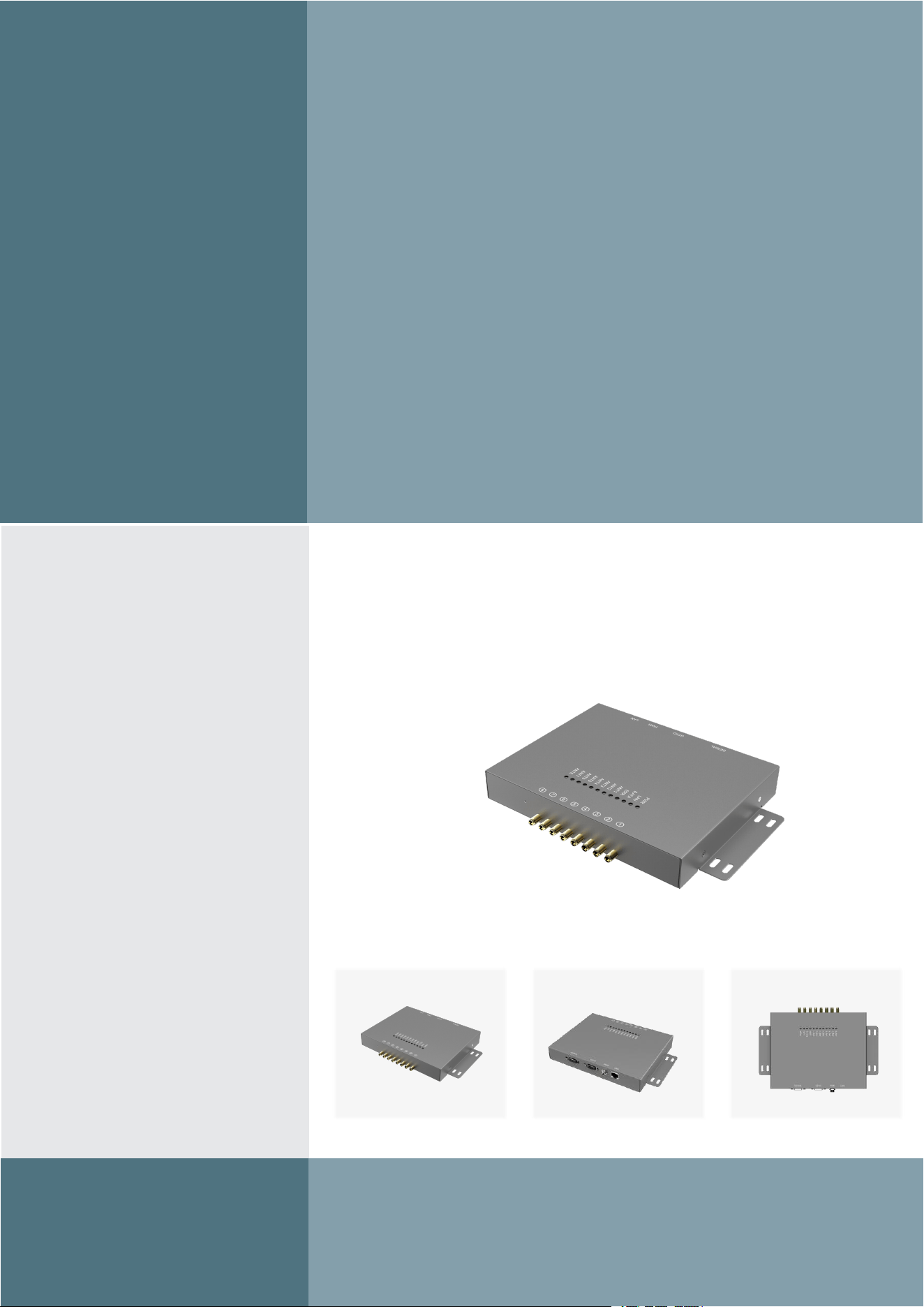
HW-RX-E8P Reader
UHF RFID Operation Manual
Operation
manual

catalogue
1 Introduction
..............................................................................................................................3
1.1 Overview
.......................................................................................................................3
1.2 Electrical Parameters
.................................................................................................... 4
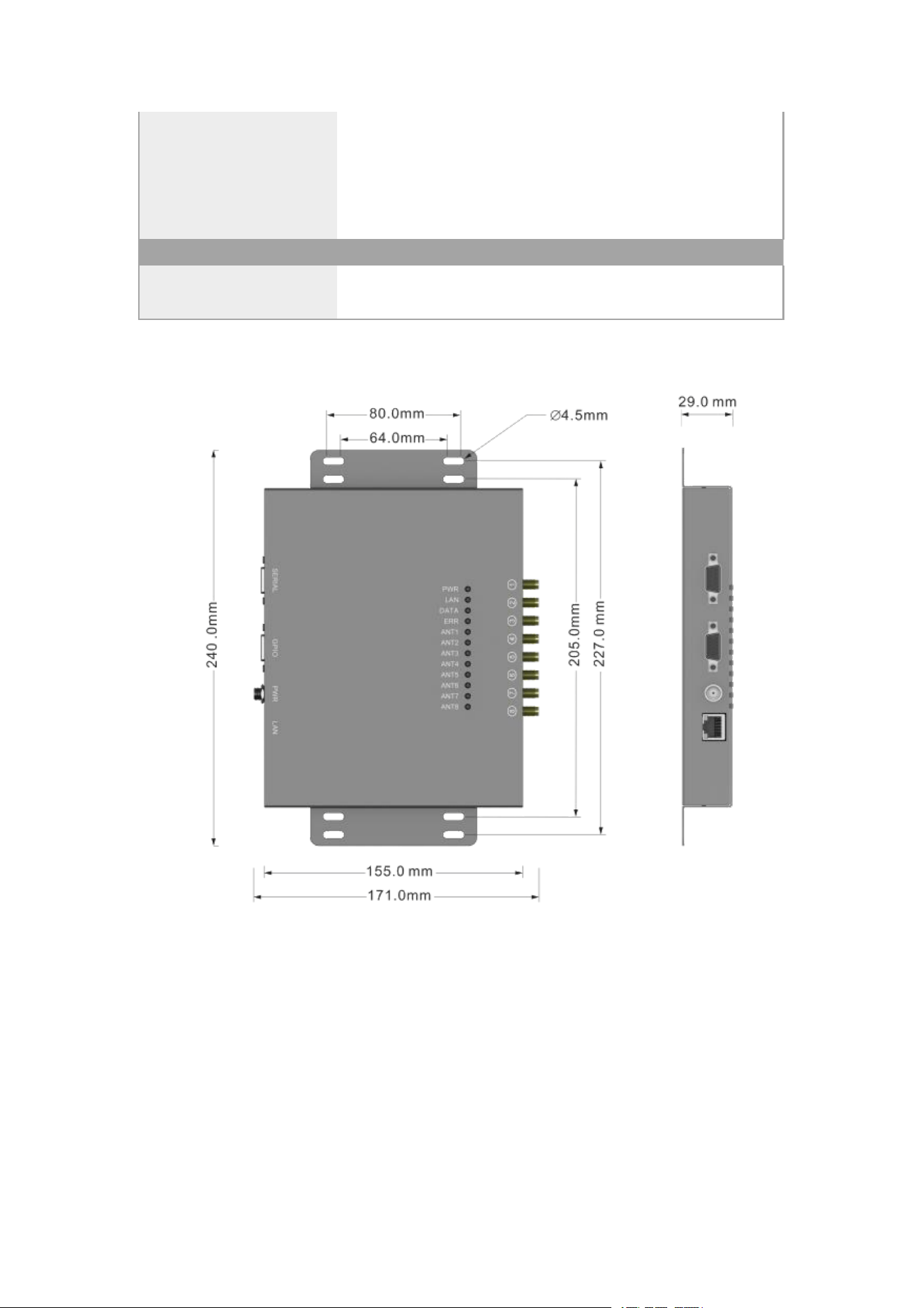
1.3 RFID Device Dimensions
.............................................................................................5
1.4 Antenna options
............................................................................................................ 6
2 Device Interface
.......................................................................................................................7
2.1 Power Interface
.............................................................................................................8
2.2 Serial Interface
..............................................................................................................9
2.3 TCP/IP Network Port
..................................................................................................10
2.4 GPIO interface
............................................................................................................10
2.5 Status Indicator Light
................................................................................................. 11
2.6 Bee-buzzing Indicator
................................................................................................ 12
2.7 Reset Hole
...................................................................................................................12
3 Equipment Installation
...........................................................................................................13
3.1 Installation Preparation
...............................................................................................13
3.2 Hardware Connection
................................................................................................. 14
3.2.1 GPIO Pin Sequence
......................................................................................... 15
3.2.2 Antenna Usage
.................................................................................................16
3.2.3 GPI Input Peripheral Devices
..........................................................................17
3.2.4 GPO Output Peripheral
................................................................................... 19

1 Introduction
1.1 Overview
The HW-RX-E8P is an ultra-high-frequency (UHF) eight-channel reader developed in-house
by our company. Featuring exceptional sensitivity, superior channel isolation, and reliable
inventory management capabilities, it delivers stable performance with a wide voltage supply
range. The device integrates multiple communication interfaces including RJ45, RS232. Its 8 RF
antenna ports significantly reduce peripheral hardware requirements, making it fully compatible
with complex environments such as warehousing, logistics, and manufacturing.
Excellent reading sensitivity, with a sensitivity as high as-85dBm
With an excellent reading range and antenna, it can identify tags up to 12 meters away.
Excellence in collision avoidance algorithms, with a maximum tag recognition rate of 900
pcs/s
Multiple communication modes with integrated RJ45, RS232 interfaces
High power output, with a maximum output power of 25.32dBm
8-Bit RF Interface for Multi-node Recognition Applications
Ultra-thin body design, ideal for applications with specific size requirements
Global Gen2 Platform, Adapting to RFID Application Needs in Different Countries and
Regions

1.2 Electrical Parameters
Radio frequency characteristics
RF Protocol
EPC Global Class1 Gen2(ISO 18000-6C)
Transmit Peak Power
25.32dBm
Frequency
United States: 902.75-927.25MHz
Inventory Rate
Max.900tag/s
Reading Range
12 meters (read range varies by tag type)
Antenna Interface
8-channel SMA-K (external thread, internal hole) connector
RSSI
support
Receiving Sensitivity
-85dbm
Interface
Ethernet
TCP Server,TCP Client,UDP
Serial
RS232
GPO
Terminal block with 4-channel optocoupler isolated outputs
(compatible with 5-24V voltage levels), featuring low-level
current tolerance Max.500mA
GPI
Terminal block with 4-channel optocoupler isolated inputs,
supports PNP opto-coupler connection, compatible with 5-24V
voltage levels
Electronics
Supply Voltage
24VDC
Mechanics
Dimensions
No interfaces or fittings included:
240.0mm(L)*155.0mm(W)*29.0mm (H)
Includes interface and mounting parts:
240.0mm(L)*171.0mm(W)*29.0mm (H)
Weight
850g
Housing
metal plate
Housing Color
dark grey
Status indication
Indicator Definition
PWR: Power Supply Indicator. If it remains illuminated, the
power supply is functioning normally.
LAN: Network status indicator. If it stays on, the network is
connected.
DATA: Data indicator, flashing indicates data interaction
ERR: Error indicator. A persistent light indicates a device failure.
Work Environment
Operating Temp.
-25
℃
~60
℃
1.3 RFID Device Dimensions
Storage Temp.
-40
℃
~85
℃
Operating Humidity
10%~95% RH, no condensation
Application
various complex environments such as warehousing logistics and
production manufacturing
Others
upgrade
Support firmware upgrade
Development
Provide a C# SDK

1.4 Antenna options
RFID Portal Antenna: HW-AB10010
Bottom Antenna NO.12: HW-AP8040
Specification
parameter
Frequency Range
902.75MHz-927.25MHz
Gain
10dBi
VSWR
≤1.5:1
Polarization
circular polarization
Input Impedance
50Ω
Material
FR4
Connector
SMA-J
Dimension
480.0mm *420.0mm *2.0mm
Specification
Parameter
Frequency Range
902.75MHz-927.25MHz
Gain
10.5dBi
VSWR
≤1.3:1
Polarization
circular polarization
Input Impedance
50Ω
Material
Steel, aluminum alloy, RF4
Connector
SMA-K
Dimension
460.0mm×220.0mm×32.5mm
2 Device Interface
The HW-RX-E8P reader features a comprehensive array of interface resources, providing
users with multiple communication solutions:
24VDC wide voltage DC power supply interface;
TCP/IP network interface function;
RS232 serial interface;
8-channel SMA-K antenna interface;
An external lead-in port with 4 input and 4 output opto-isolated GPIO interfaces, compatible
with 24VDC.
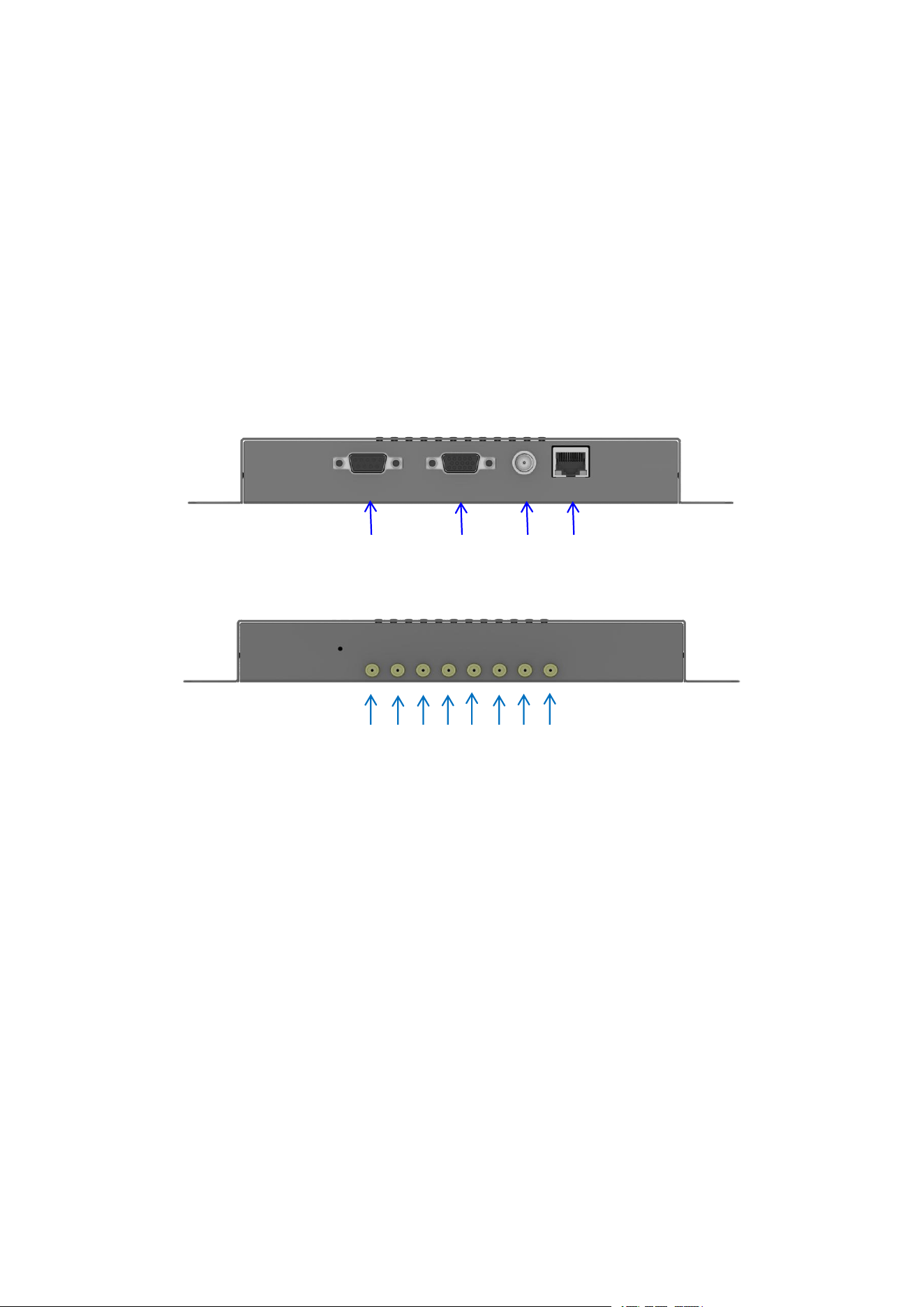
The HW-RX-E8P interface is shown in the figure below:
Figure 2-1 Schematic diagram of device interface
SERIAL GPIO PWR LAN
ANT8 7 6 5 4 3 2 1
2.1 Power Interface
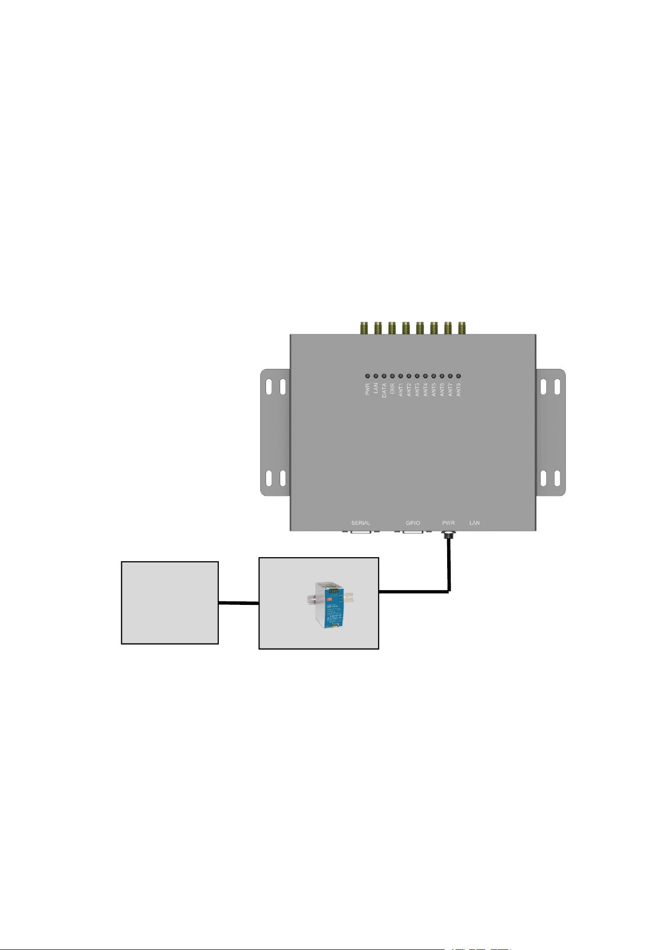
The device features a 24VDC power input and can be powered through the PWR interface
(connector terminal).
24VDC wide voltage DC power supply. We recommend switching power supplies for
optimal performance.
brand
:
MW
,
Model
:
NDR-240-24
Input: 100-240VAC 2.8A 50/60Hz
Output:24VDC,10A
Figure 2.1-1 Schematic diagram of power supply wiring
24VDC/10A adapter
100-240VAC
2.8A
50/60Hz
2.2 Serial Interface
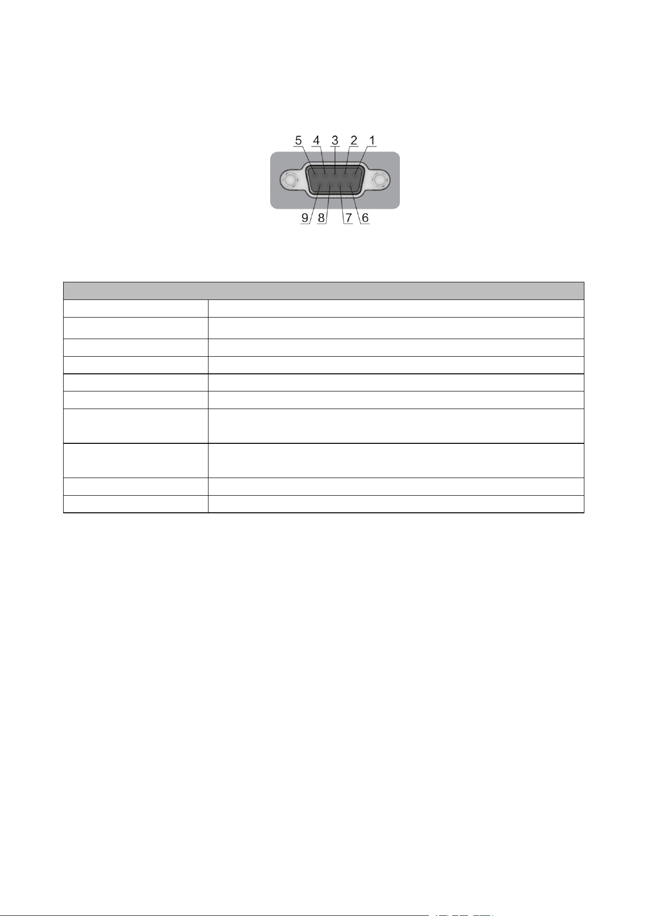
The serial interface uses a DB9 female connector, as shown in the diagram below.
Figure 2.2-1 Schematic diagram of serial interface
This serial port supports multiple communication protocols, with RS232 as the default
interface. The pin definitions are as follows:
DB9 Motherboard Pin Definitions
Pin number
Interface function: Isolated RS232
PIN 1
485A (Customizable)
PIN 2
RS232TXD
PIN 3
RS232RXD
PIN 4
485B (Customizable)
PIN 5
GND
PIN 6
RFU(Reserved for Future Use)
PIN 7
RFU(Reserved for Future Use)
PIN 8
CANL (Customizable)
PIN 9
Customizable CANH
Table 2.2-1 DB9 Serial Interface Pin Definitions
2.3 TCP/IP Network Port
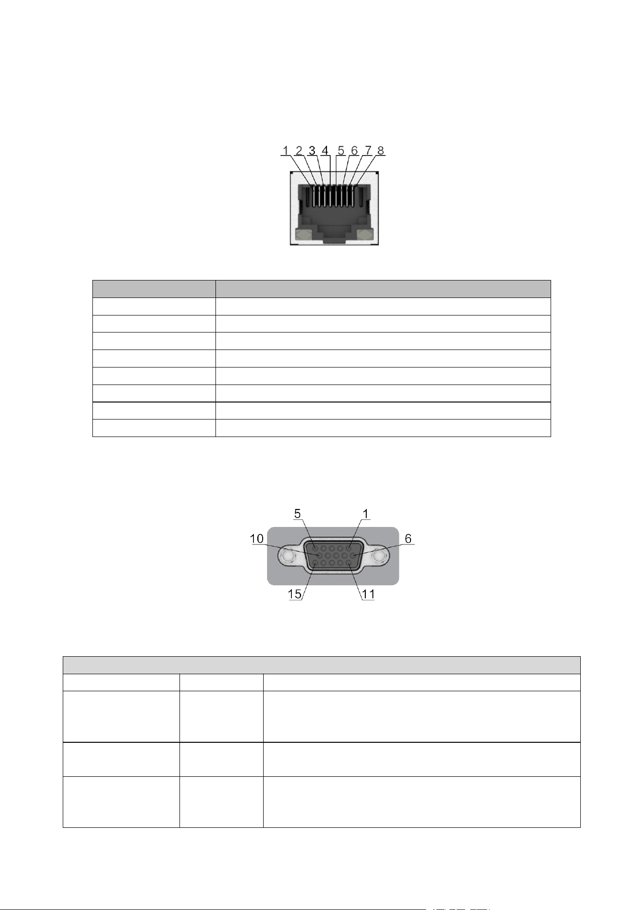
The RFly-R6 reader supports TCP/IP communication through an RJ-45 aviation-grade
network port, as shown in the interface diagram below.
Figure 2.3-1 Schematic diagram of TCP/IP interface
The TCP/IP network port definitions are shown in the table below:
Pin number
Interface function: TCP/IP network communication
PIN 1
TX+
PIN 2
TX-
PIN 3
RX+
PIN 4
POE V+
PIN 5
POE V+
PIN 6
RX-
PIN 7
POE V-
PIN 8
POE V-
Table 2.3-1 TCP/IP Network Port Definitions
2.4 GPIO interface
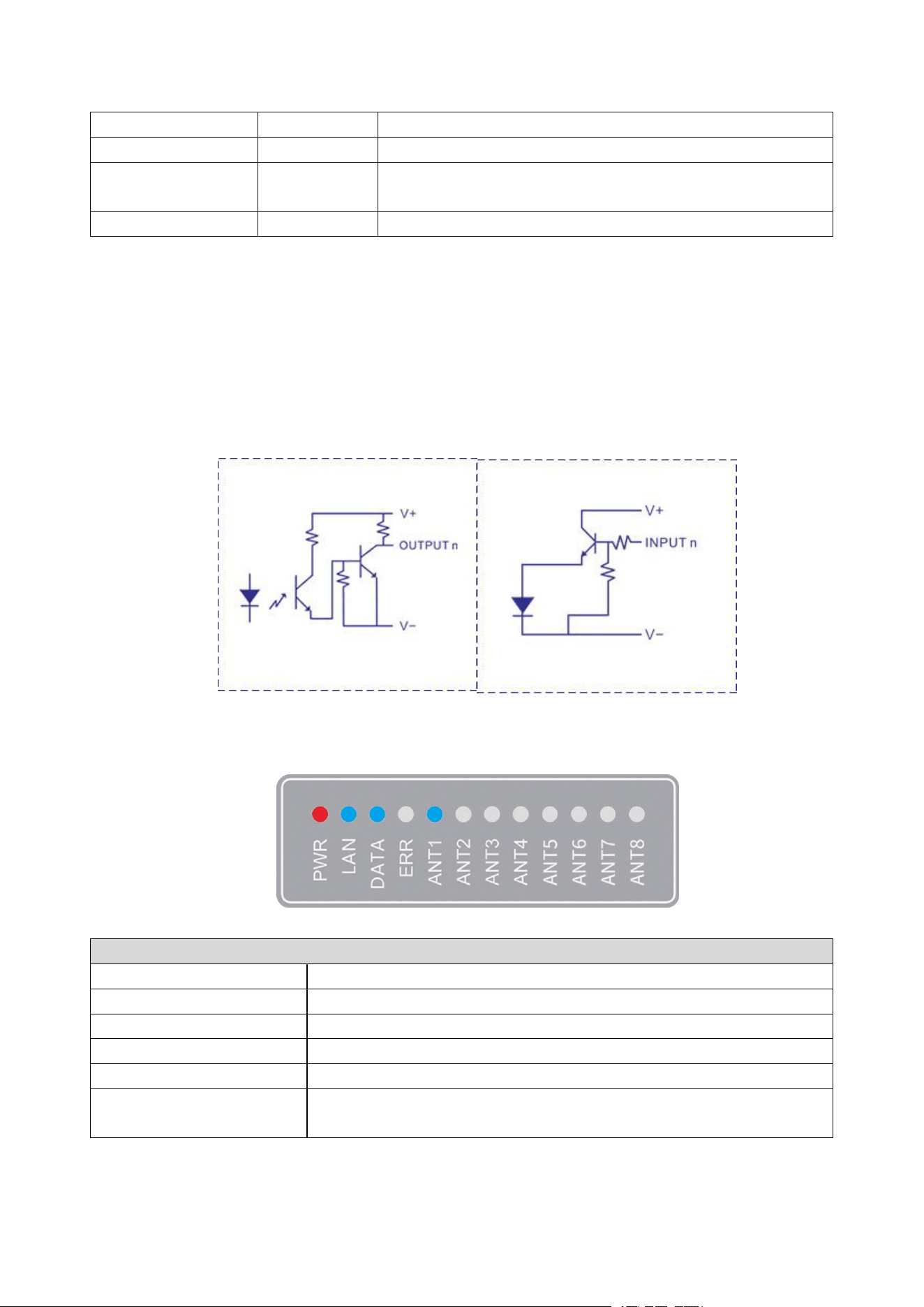
The GPIO interface uses a DB15 female connector for output.
Figure 2.4-1 Schematic diagram of the GPIO interface
The GPIO interface features 4 input and 4 output channels, with its configuration details as
shown in the table below:
GPIO Pin Definitions
quotation marks
definition
function
PIN 1
~
PIN4
GPO1
~
GPO4
A universal logic output port compatible with 5-24V voltage
levels, featuring a low-level current tolerance of up to 500mA.
This capability is not available for high-level outputs.
PIN 5
OPT VCC
Input of opto-isolated power supply (external power source),
operating voltage range: 5-24V
PIN6
PWR OUT
The auxiliary power output delivers a voltage of approximately
PWR voltage minus 0.5V, providing an external power supply
with a maximum output of 18W (depending on the power adapter)
and a maximum output current of 750mA.
PIN 10
OPT GND
ground of photoelectric isolation (external power supply)
PIN 11~PIN14
GPI1~GPI4
General-purpose logic input port, compatible with 5-24V voltage
levels
PIN 15
GND
Equipment location
Table 2.4-1 GPIO Pin Definitions
PIN 5 and PIN 10 are external power input terminals, which provide power to the GPIO and
its connected peripherals (e.g., alarm).
PIN6 and PIN15 (PWR OUT) serve as auxiliary power outputs, providing internal power to
the device. When external power is unavailable for the GPIO ports (PIN5 and PIN10), these pins
can be connected to supply power to the GPIOs. Note that the opto-isolation function is disabled
when the GPIOs are powered externally, but remains active when powered through PIN6 and
PIN15's PWR OUT.
The principle of GPI and GPO circuit is as follows.
Figure 2.4-2 GPIO Circuit
2.5 Status Indicator Light
Figure 2.5-1 Schematic diagram of status indicator lights
state indicator definition
pilot lamp
state definition
PWR
Power indicator: The red light remains on when power supply is normal.
LAN
The network port is connected and always on
DATA
Data is flashing
ERR
Error message: The red light stays on for device abnormalities
ANT1-ANT8
Antenna indicator: displays the current open antenna port number in
blue
Table 2.5-1 Status Indicator Definitions
GPO Circuit
GPI Circuit

2.6 Bee-buzzing Indicator
bell definition
warning tone
deictic function
Ding-dong-ding
The device started normally
1 short (one sound)
network malfunction
1 long, 1 short (two
sounds)
RF module failure
1 long, 2 short (three
sounds)
Both the network and RF modules are experiencing simultaneous
failures
Table 2.6-1 Definition of Beezer
2.7 Reset Hole
The device has a reset hole on the back, as shown in the figure below. Press the reset button
in the hole to restart the product.
Figure 2.7-1 Schematic diagram of reset hole
RESET
3 Equipment Installation
3.1 Installation Preparation
Before setting up the test platform, you need to prepare the following equipment and
materials:
1 HW-RX-EXP reader/writer;
Includes a standard 24V switch-mode power supply;
Includes 1 standard network cable.
1 GPIO communication line;
1 RS232 serial cable
1 power cable;
8 antenna feed lines;
UHF antenna: RFID Portal Antenna (model HW-AB10010), quantity: 1 to 8 units
UHF antenna: Bottom Antenna No.12 (HW-AP8040), quantity: 1-8 units
1 digital peripheral
EPC C1G2/ISO 18000-6C: Several UHF tags;
One PC running Windows XP or later;
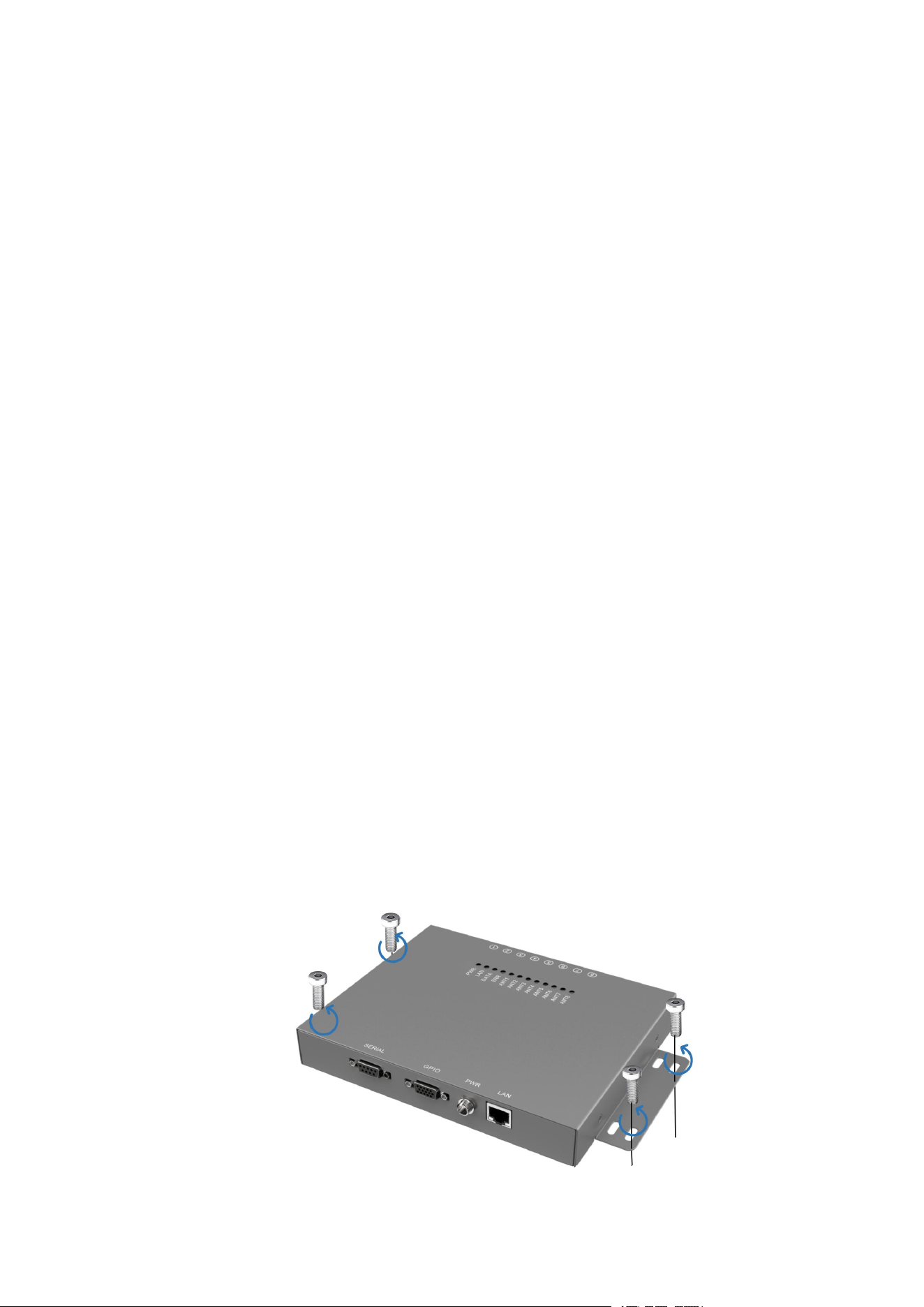
Before connecting the device, install it in a secure and reliable location on-site. As shown in
the figure below:
Recommended screw size: M4*12
Figure 3.1-1 RFID Reader Installation Diagram
3.2 Hardware Connection
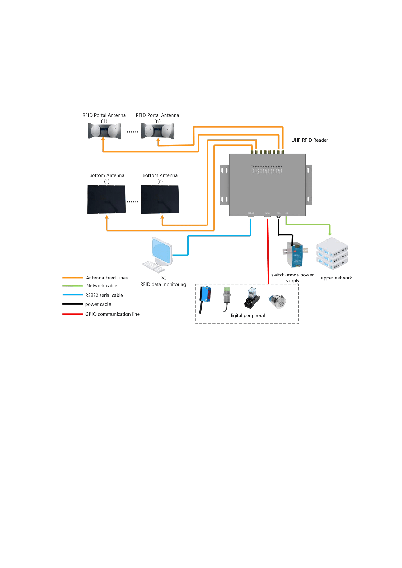
Recommended hardware connection sequence: Antenna feeder → Communication network
cable → Power adapter → RS232 serial port. The connection diagram is shown below:
Figure 3.2-1 Schematic diagram of UHF RFID Reader connection
3.2.1 GPIO Pin Sequence
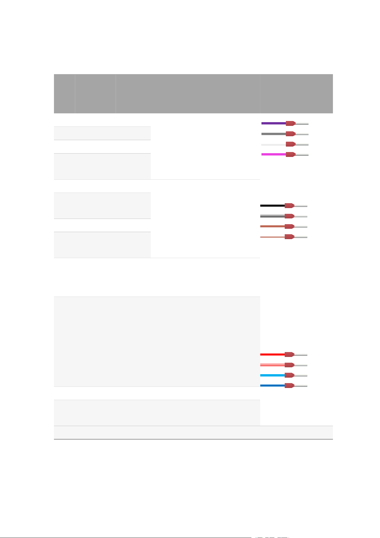
order
num
ber
wire
marking
Line
Color
Sequence definition
1
GPI1
purple
General-purpose logic input port,
compatible with 5-24V voltage levels
2
GPI2
gray
3
GPI3
white
4
GPI4
pink
colour
5
GPO1
black
A universal logic output port
compatible with 5-24V voltage levels,
featuring a low-level current
tolerance of up to 500mA. This
capability is not available for
high-level outputs.
6
GPO2
black and
white
7
GPO3
brown
8
GPO4
Brown
and white
9
VCC_IN
red
Input of opto-isolated power supply
(external power source), operating
voltage range: 5-24V
10
PWR_OUT
Red and
white
The auxiliary power output delivers a
voltage of approximately PWR
voltage minus 0.5V, providing an
external power supply with a
maximum output of 18W (depending
on the power adapter) and a
maximum output current of 750mA.
11
GND
sky blue
Equipment location
12
OP_GND
blue
ground of photoelectric isolation
(external power supply)
Note: The final line number is subject to the line number label.
VCC-IN
PWR-OUT
GND
OP-GND
GPO1
GPO2
GPO3
GPO4
GPI1
GPI2
GPI3
GPI4

3.2.2 Antenna Usage
The HW-RX-E8P UHF RFID Reader supports two antenna configurations: either the
HW-AB10010 RFID Portal Antenna or the HW-AP8040 Bottom Antenna No.12. Users can adjust
the number of antennas based on their specific operational needs.
Number
Antenna name
Antenna
model
key
parameter
way to install
1
RFID Portal
Antenna
HW-AB10010
Antenna
gain :
10.5 dBi
It can be mounted on a metal
backplate bracket, with its upper
surface covered by either a plastic
or POM (polyoxymethylene)
casing, and connected via a
feeder.
2
Bottom Antenna
NO.12
HW-AP8040
Antenna
gain
:
10 dBi
It can be mounted on a metal
backplate bracket, with its upper
surface covered by either a plastic
or POM (polyoxymethylene)
casing, and connected via a
feeder.
3.2.3 GPI Input Peripheral Devices
The GPI input pins of the HW-RX-E8P UHF RFID Reader primarily support external devices
with switchable outputs, including PNP/NPN photoelectric switches, proximity sensors, and
push-button switches. Alternatively, these pins can connect to either normally open (NO) or
normally closed (NC) contacts of relays.
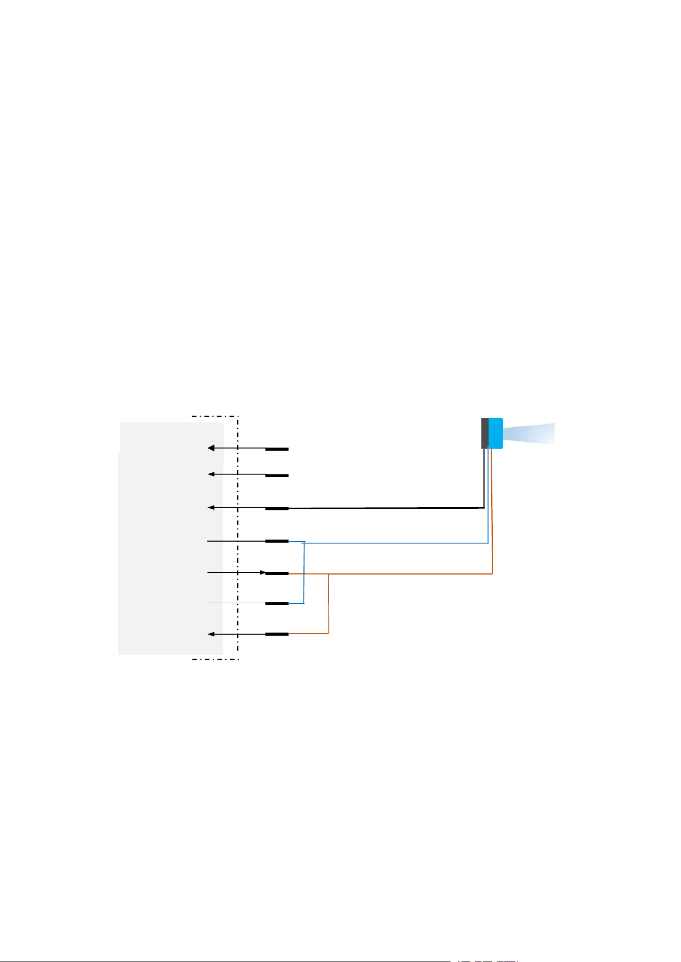
3.2.3.1 Photoelectric Sensor or PLC Q-point wiring (non-isolated
type)
Non-isolated GPIO: The power supply for the photoelectric sensor is provided by the
reader’s internal power source. Pay attention to the reader supply voltage should not exceed the
limit range of the photoelectronic sensor (usually DC10 ~ DC30V).
PLC Q-points can also be used to trigger the reader, pay attention to level matching and
signal common ground.
Q
GPI3
GPI2
GPI1
GND-
PWR-OUT
OP-GND
VCC-IN
M
L+
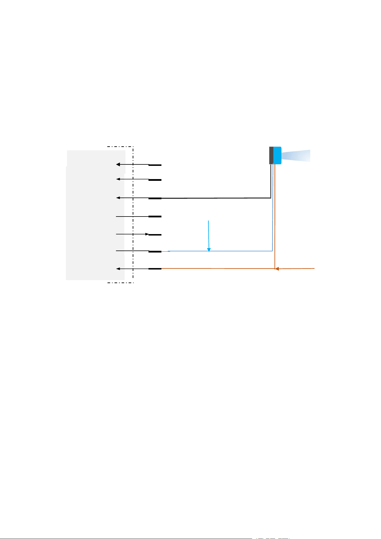
3.2.3.2 Photoelectric Sensor or PLC Q-point wiring (isolated
type)
Isolated GPIO: The power supply for the photoelectric sensor is provided by the external
power source.Pay attention to the external supply voltage should not exceed the limit range of the
photoelectronic(usually DC10~30V).
PLC Q-point can also be used to trigger the reader, pay attention to the level matching and
signal common ground.
Q
GPI3
GPI2
GPI1
GND
PWR-OUT
OP-GND
VCC-IN
M
L+
External power negative(DC 0V)
External power positive(DC 5~24V)
3.2.4 GPO Output Peripheral
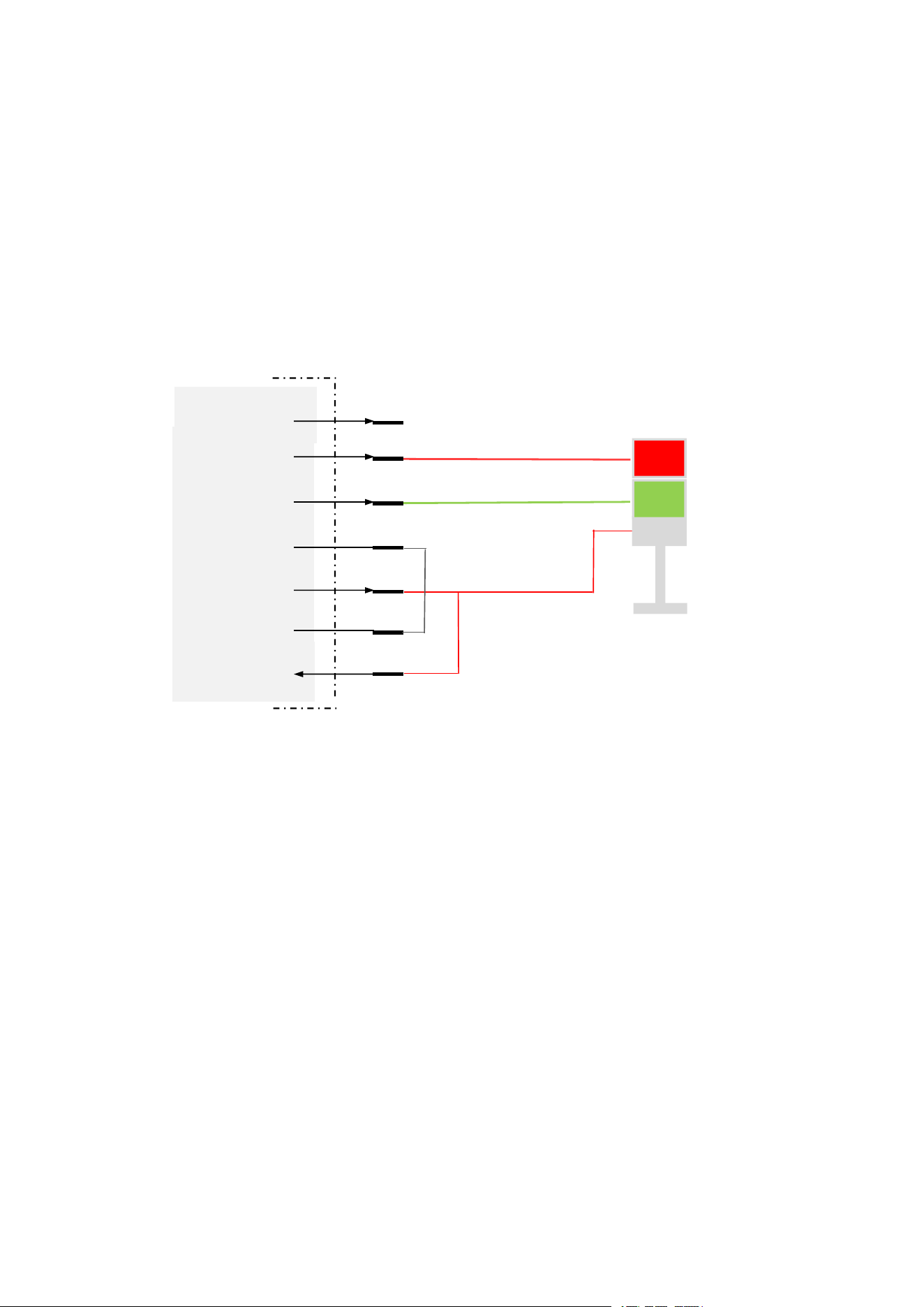
3.2.4.1 Alarm Lamp Wiring Diagram
(1)Non-isolated GPIO: The power supply for the Alarm lamp is provided by the reader’s
internal power source.If the reader is powered by DC12V or POE, the voltage of the alarm lamp
should be 12V; if the reader is powered by 24V, the voltage of the alarm lamp should be DC24V.
After connecting the cables, the corresponding GPO can be set to low level to light up the alarm
lamp.
RED
GREEN
COMMON
GPO3
GPO2
GPO1
GND
PWR-OUT
OP-GND
VCC-IN
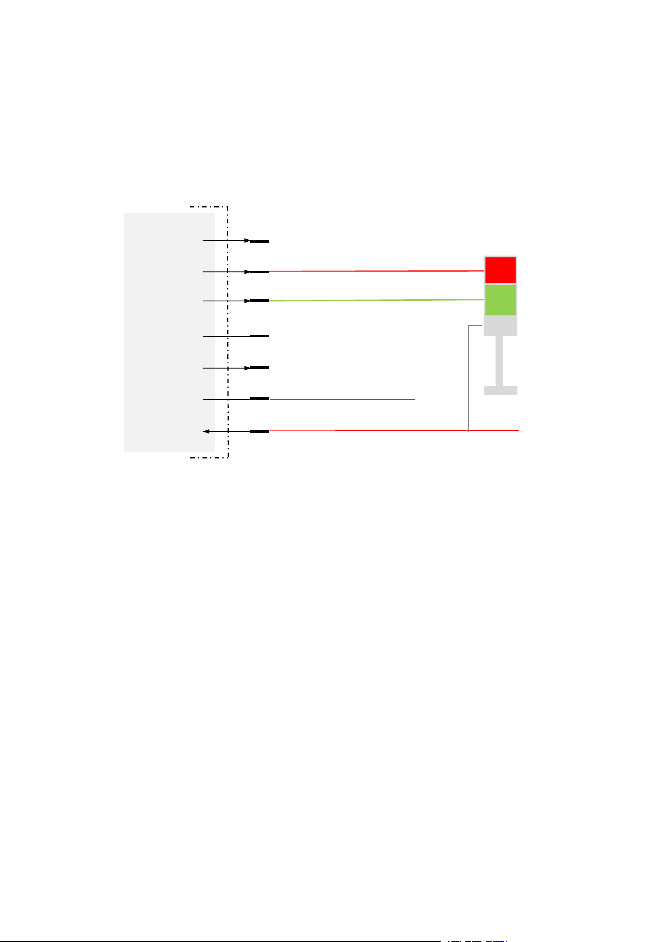
(2)Isolated GPIO: The power supply for the Alarm lamp is provided by the external power
source.The voltage of the alarm lamp should be the same as that of the external isolated power
supply (range DC5V-24V), and the recommended voltage is DC12V or DC24V; the external
isolated power supply should be independent of the main power supply of the device, or else it
will not be able to isolate the power supply. After connecting the cable, the corresponding GPO
can be set to low level to light up the alarm lamp.
GPO3
GPO2
GPO1
GND
PWR-OUT
OPT-GND
VCC-IN
RED
GREEN
COMMON
External power positive(DC 5~24V)
External power negative(DC 0V)
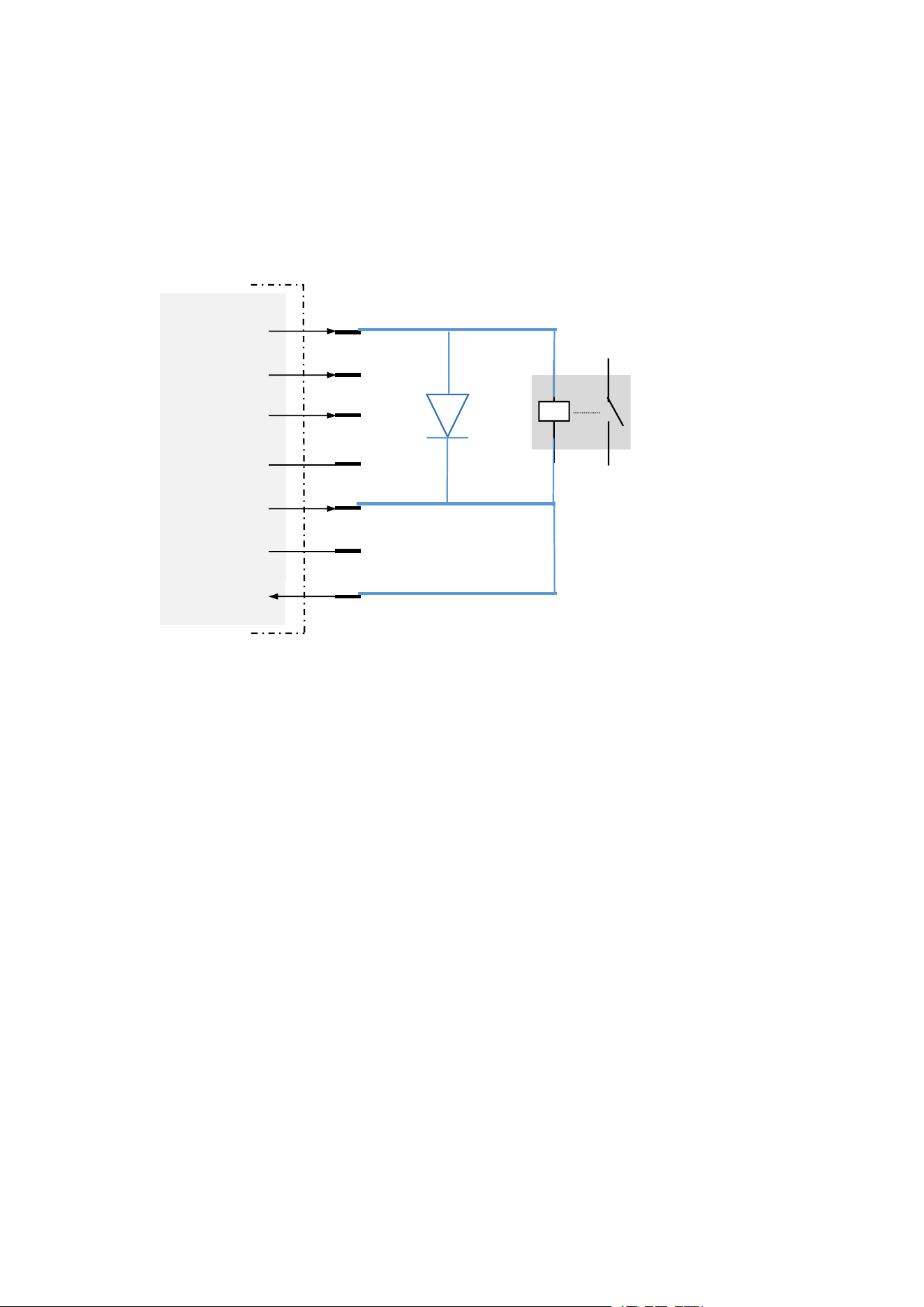
3.2.4.2 Relay Wiring Diagram
When the reader GPO current driving capability is insufficient, it can be connected to an
external SSR(Solid State Relay), and drive the relay through GPO low level (default set high) to
indirectly drive the work of higher power appliances. (Here take GPO non-isolated power supply
as an example).
GPO3
GPO2
GPO1
GND
PWR-OUT
OPT-GND
VCC-IN
A1
A2
T2-
T1+
Solid State Relay