1
Installation Guide & User Manual
FR1300
Version: 1.0.1
Date: November, 2014
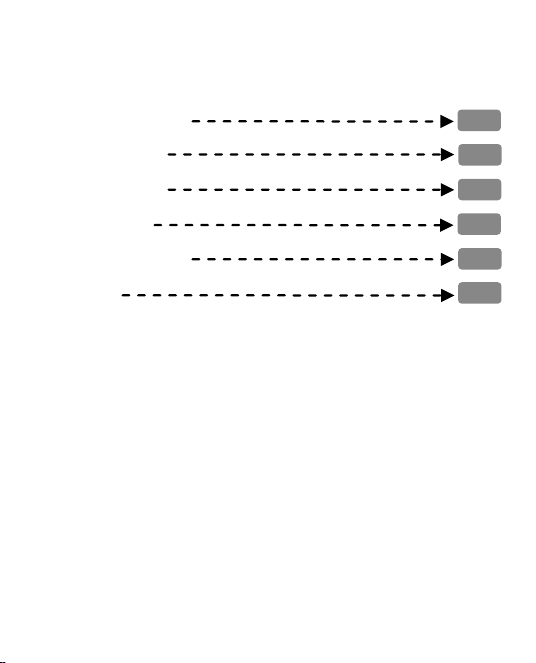
Contents
1. Device Installation
2. Work Principle
3. Other Functions
4. Verify Mode
5. List of Parameters
6. Cautions
1
1
3
4
8
9
1
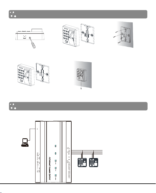
1. Device Installation
(2) Take away the
back cover.
(3) Fix the back cover on
the wall according to
the mounting paper.
(4) Fix the device to the
back cover.
(5) Fix the screw.
2. Work Principle
(1) Connection with Control Panel
Less than 9 Readers can be connected
with the Control Panel at present.
+12V
GND
485-
485+
PC
Access Control Panel
(1) Remove the screw on
the bottom of device.
EX T
RS4 85
PC
RS4 85
S TATE
P WR
REA DER 2REA D ER1
SW ITC H
OUT
A C T
2
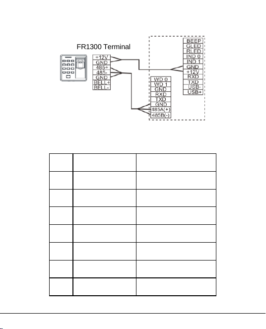
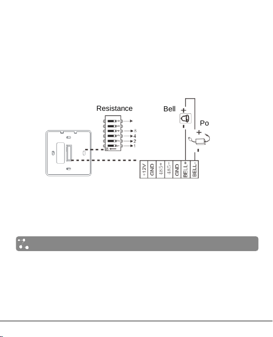
(2) Connection with Standalone Access Control
(3) The terminal definition table of Reader
No.
Terminal Name
Function
1
12V
12V Power Input
2
GND
Power GND
3
485+
485 Communication+
4
485-
485 Communication-
5
GND
Signal GND
6
BELL+
Door-Bell+
7
BELL-
Door-Bell-
FR1300 Terminal
Standalone Access Control
3
3. Other Functions
(1) Reset Switch
If the device does not work properly because of misoperation or other
abnormalities, you can use ‘Reset’ function.
Operation: Remove the black rubber cap, then stick the Reset button hole
with a sharp tool (diameter is less than 2mm).
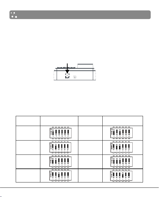
(2) Dip Switch Setting
It is adopted binary coding and little endian. Number 1~4 switches are
used to set the 485 address number (device number). The address
numbers setting by place these 4 switches are shown as the table below.
Address
Switch Setting
Address
Switch Setting
1
5
2
6
3
7
4
8
Reset Switch
Bottom View
4
Note:
1. Number 5 switch is idle.
2. The sixth switch is used to set the terminal resistance in RS485
communication: When the sixth dip switch is set in ON state, it means a
terminal resistance of 120Ω is between 485+ and 485- in parallel.
(3) Wiring Terminals
Note: When connecting With Standalone Access Control, please set
the dial code address "1" to "ON" position.
4. Verify Mode
After the reader is powered on independently, the reader can not identify
the fingerprint, password or card. In other words, the reader can not
receive data or send data without connectiong with Control Panel or
Standalone Access Control.
Operation Tips:
Wiring Terminals
Back View
Terminal
Resistance
Power Supply
Bell

5
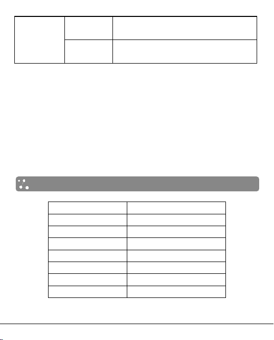
Operation
Description
Verify successfully
The indicator turns green and the buzzer
makes a long beep.
Verify failed
The indicator turns red and the buzzer makes
two short beeps.
Verify state
The indicator turns green once every two
seconds and the buzzer makes no beep.
Non-privileged
The indicator turns red and the buzzer makes
three short beeps.
Press [*] to input
password
The indicator turns off and the buzzer makes
a long beep.
A verify mode is finished
and then into next
verification
The indicator turns green three times (when a
verify mode is finished, the indicator turns
green three times,and then into next
verification when in combined verification.
The inputted user ID (or
password) is valid
The indicator turns off and the buzzer makes
a long beep.
User ID (or password) is
inputted and press [*] to
exit verification
The indicator turns red and the buzzer makes
two short beeps.
Incorret verify mode
The indicator turns red, the buzzer makes two
short beeps, and then makes a long beep.
Data transmission
abnormally
The indicator turns red, the buzzer makes a
short beep, and then makes a long beep.
Communication failed
The indicator turns red, the buzzer makes four
short beeps.

6
Validation steps:
1. When the reader connected with the access control panel, it is in
verification state.
2. Start user verification. The reader supports fifteen Verify modes: only
card, only fingerprint, card and fingerprint, card or fingerprint and so on.
Verify modes are as the follows:
Verify modes
Description
Card,
Fingerprint
and Password
First way
Punch card for verification.
Second way
Press finger for verification.
Third way
Input password for verification.
Fourth way
Press [*], and then input duress password,
press [#] to confirm at last.
Only
Fingerprint
Press finger for verification only.
Only User ID
Input user ID for verification only.
Only
Password
First way
Input password for verification only.
Second way
Press [*], and then input duress password,
press [#] to confirm at last.
Only Card
First way
Punch card for verification.
Second way
Press [*], input duress password, and then
press [#] to confirm, punch card at last.
Fingerprint or
Password
First way
Press finger for verification.
Second way
Input password for verification.
Third way
Press [*], and then input duress password,
press [#] to confirm at last.

7
Card or
Fingerprint
First way
Punch card for verification.
Second way
Press finger for verification.
Third way
Press [*], input duress password, and then
press [#] to confirm, punch card at last.
Card or
Password
First way
Punch card for verification.
Second way
Input password for verification.
Third way
Press [*], and then input duress password,
press [#] to confirm at last.
User ID and
Fingerprint
Input user ID and press finger for verification, and there is
no order.
Password and
Fingerprint
Input password and press finger for verification, and there
is no order.
Card and
Fingerprint
Punch card and press finger for verification, and there is
no order.
Card and
Password
First way
Punch card and input password for
verification, and there is no order.
Second way
Press [*], input duress password, and then
press [#] to confirm, punch card at last.
Card,
Fingerprint
and Password
Punch card, press finger and input password for
verification, and there is no order.
User ID,
Password and
Fingerprint
First way
Input user ID, and then input password,
press finger for verification at last.
Second way
Press finger, and then input password,
press user ID for verification at last.
8
Fingerprint,
Card or User
ID
First way
Press finger and punch card for
verification, and there is no order.
Second way
Press finger and input user ID for
verification, and there is no order.
Note:
1. No matter which verify mode is setted, emergency password is
effective on Control Panel. The emergency password is alse effective
on the reader when connecting with Standalone Access Control which
supports emergency password.
2. When connecting with Control Panel or Standalone Access Control,
the firmware on device decides verify modes.
3. For how to set verify modes, please read the software user manual.
5. List of Parameters
Item
Note
Power Supply
DC 12V/3A
Fingerprint Collecter
IR fingerprint reader
Key Type
Sensitive switch
Verify Mode
Fifteen verify modes
Communication
RS485
Buzzer
Prompt "di-di"
Indicator
Two colour: red and green

9
6. Cautions
Connect GND cable firstly, and power cable is connected after all the
other wiring.
It is recommend to use the DC 3A/12V power supply.
Keep the exposed part of wire is less than 5mm to avoid unexpected
connection, and result in machinery damage.
Recommend operating temperature range: 0°C ~ 45°C.
It is recommend that the distance of 485 communication is less than
200 meters when power supply independently; It is recommend that
the distance between power supply and decvice is less than 100
meters, and connecting less than 5 readers when sharing power with
Control Panel.


