Operator’s Manual
www.mechmaxx.com
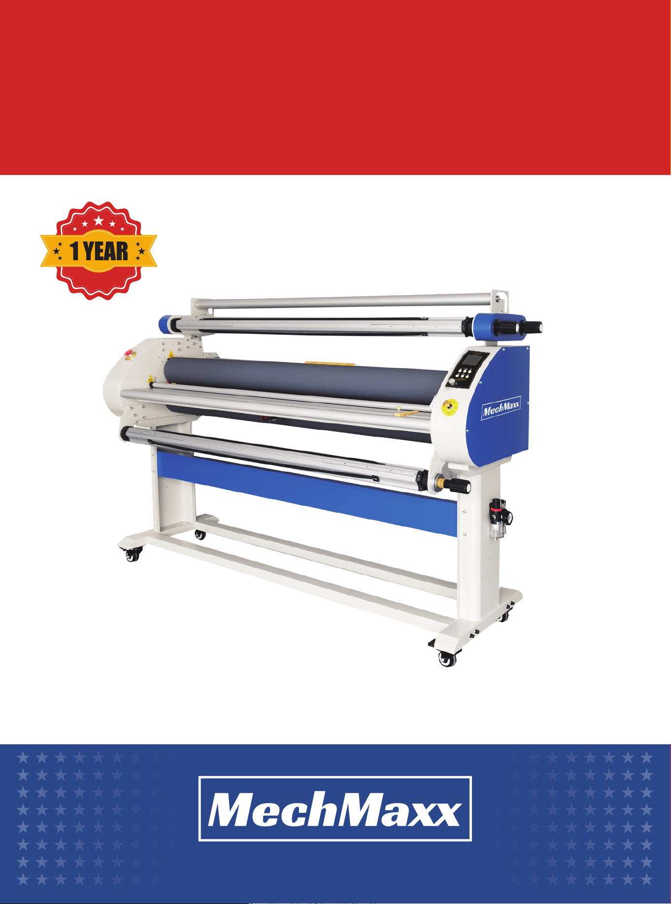
WARRANTY
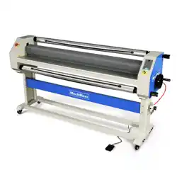
FULLY AUTOMATIC COLD
AND WARM LAMINATOR

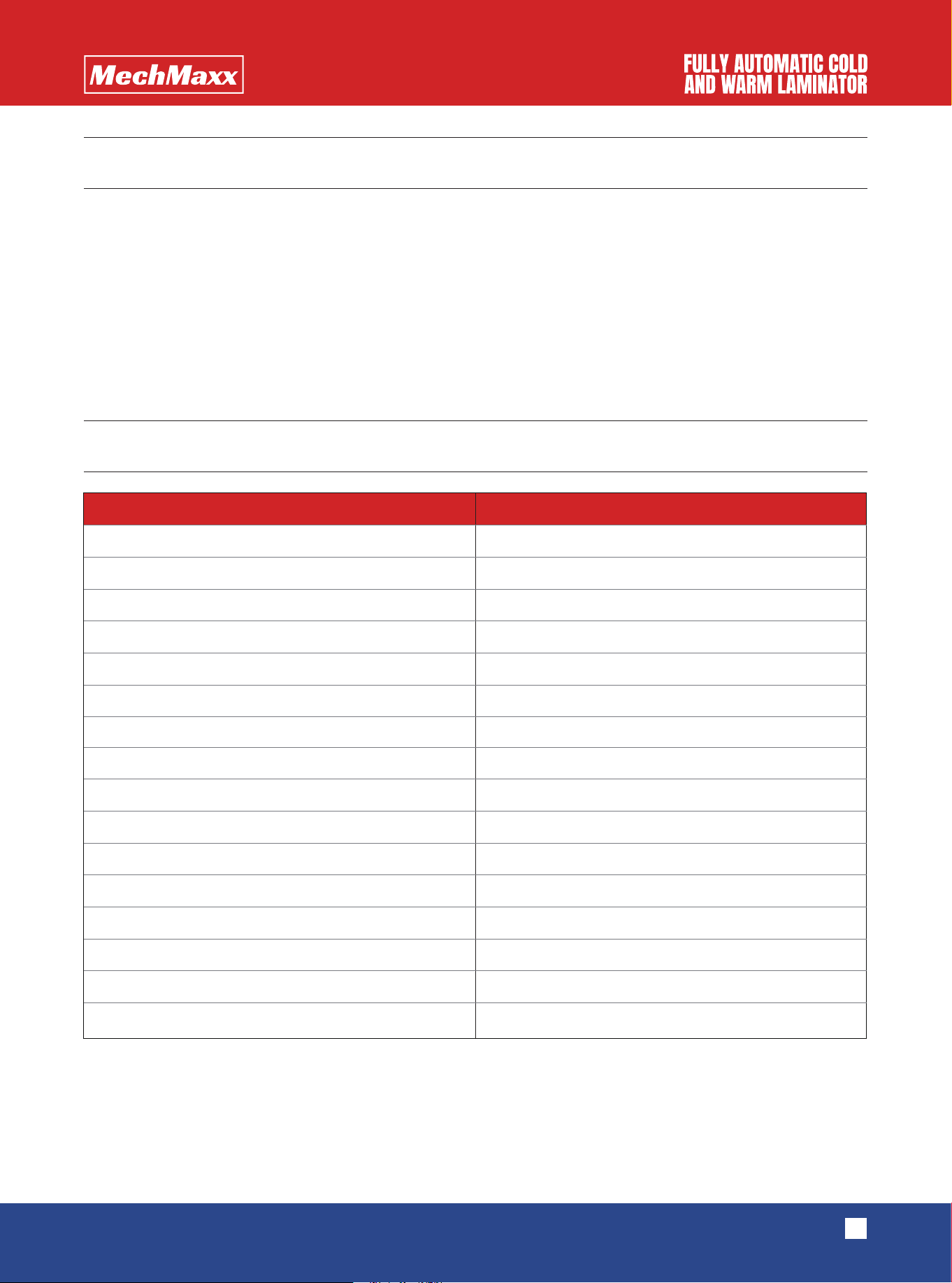
EQUIPMENT DESCRIPTION
TECHNICAL PARAMETERS
1
www.mechmaxx.com
This WK1700-A3 full automatic cold and warm laminating machine is a new type of coating equipment, which has the
functions of automatic stripping of paper lining and photo winding. The bottom roll is driven by a motor, and the film with
rubber surface and the picture are pressed and driven by the top roll and the bottom roll to form an automatic stripping of
lining paper, which is to form the linear internal force movement of the printed image between the main rolls and avoid
the tedious manual winding. Labor saving and simple operation. Because of its innovative structure, it has been
welcomed by users since its launch.
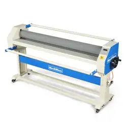
The machine has four film mandrels and two silicone rollers to support continuous film or long picture film coating. And
through the rolling force of the main roll, the automatic stripping and photo winding of the lining are realized. It is easy to
use, efficient, energy-saving and easy to adjust speed.
Maximum Width
Maximum speed
Max Lifting Height
Roller material
Top Roller Diameter
Bottom roller diameter
Heating Mode
Max Temperature
Heating Power
Lifting Method
Motor Power
Voltage
Equipment Size
Packaging Size
Net Weight
Gross Weight
63.78 in(1620mm)
16 m/min
1.1 in(28 m)
Silica Roller
5.12 in(130 mm)
5.12 (130 mm)
Infrared Heating
158 ℉(70 ℃)
2000 W
Pneumatic Lifting
140 W
110V
78.74*31.5*53.54 in (2000X800X1360 mm)
86.61*31.5*29.13 in (2200X800X740 mm)
429.9 lbs(195 kg)
485.02 lbs(220 kg)
Model
1700-A3
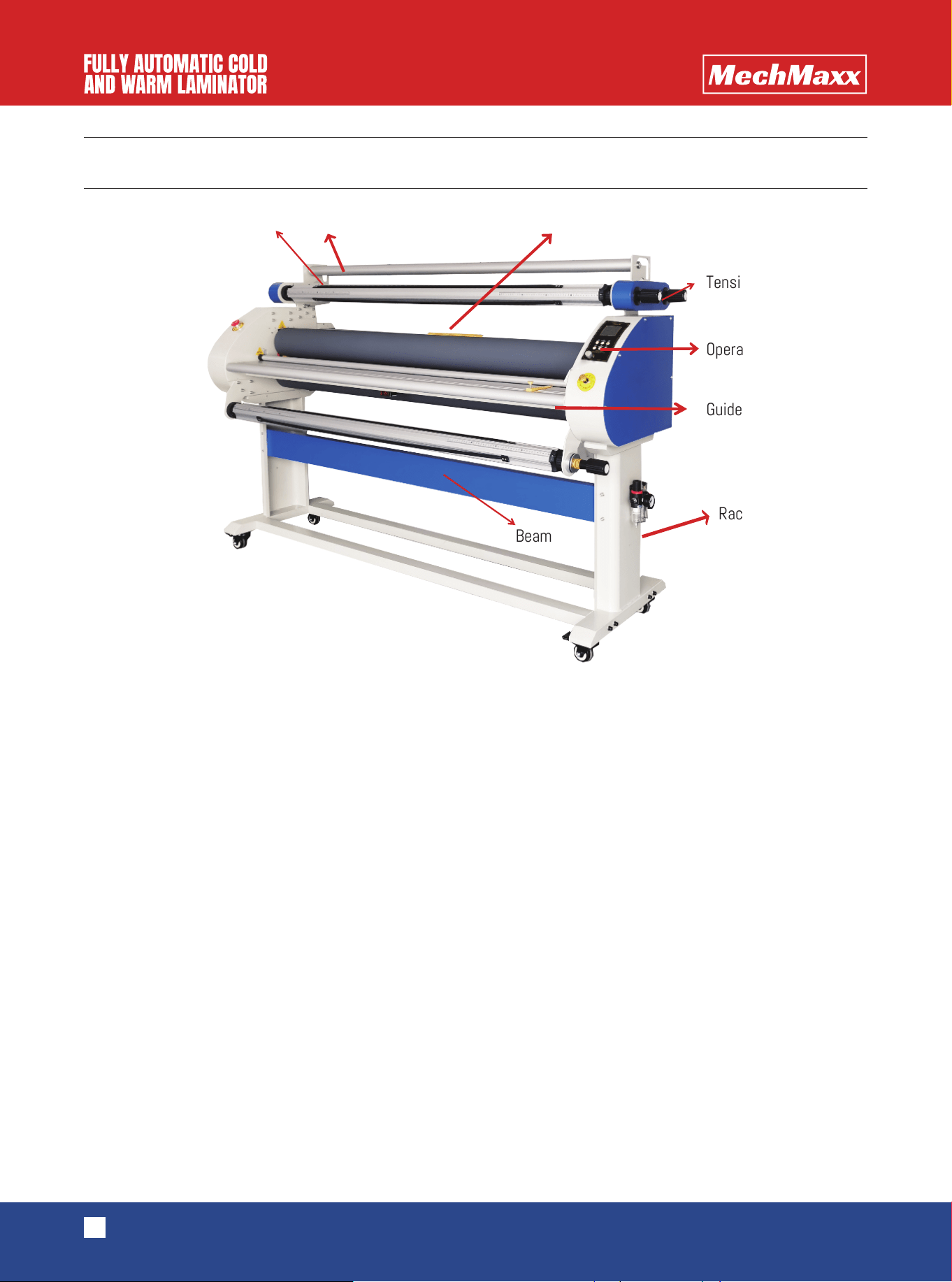
PART NAME
2
www.mechmaxx.com
1. Top and bottom rollers
The top roll and bottom roll are one of the most important parts of the film covering machine, whose material is silica gel.
Silica gel has the characteristics of high temperature resistance, wear resistance, corrosion resistance and non-sticky.
2. Drawing axis, film axis, paper axis and finished product axis
The four mandrels are composed of aluminium rods, aluminium heads, bearings, rubber strips and other components. The
outer diameter is controlled within 3 inches, which facilitates the loading and unloading of conventional film products on
the market, such as yellow film, laminating film and so on. In the operation process, rubber strips play a slippery role to
ensure that there is no sliding, too loose, too tight and so on.
3.Pneumatic switch and cylinder
Pneumatic switch has upper, middle and lower three gears. In the case of air in the equipment, the top roll can be lifted
up, the top roll can be lowered down, and the middle gear can temporarily lock the air inflow and output. The cylinder type
of this equipment is SDA50-30, which makes the lifting height of top roll more than 28 mm. With the use of pneumatic
system, the lifting and descending of top rollers are synchronized, and the re-pressure plays a key role.
4.Emergency stop switch
When the machine is in an emergency or dangerous state, the power supply can be cut off by the emergency stop switch
and the equipment can be stopped to protect the safety of the person and equipment.
5.Cutter (optional)
The use of cutting knife can make it possible to cut vertically and white edges at the same time in the process of film
covering.
6.Tighten your grip.
Aluminum bar Pressed aluminum rod Cutting knife
Tension handle
Operation panel
Guide rod
Rack foot
Beam
ppane

3
www.mechmaxx.com
7.The tightening handle is mainly used to adjust the tightening force of four mandrels. Before leaving the factory, the
four handles have been debugged accordingly. Users can use them directly. The tightening force is increased by twisting
clockwise; the tightening force is reduced by twisting counterclockwise.
8.Simple panel
(1)
“
Ready” ” means start to laminating
(2)
” “Stop”” means pause, and the pedal switch can only be used in this state
(3)
” “Forward”” means laminating
(4)
“ “Backward” ” means reverse laminating
(5)
“ “Cold””The machine operates in room temperature
(
6
)
” “Hot””It means that the temperature is too low during the process of laminating, and the
rubber rollers should be heated
(
7
)
“
Speed” Control Knob: speed can adjust from 1-9 gear
4
www.mechmaxx.com
OPERATION INSTRUCTIONS
1.Operation steps
(1)Turn on the main power supply.
(2)If the room temperature is higher, cold mounting is preferred. If the room temperature is low or can not reach the
temperature required for film covering, press the single roll heating key, then press the temperature setting key, press the
rising key, set the required temperature to wait for heating, and then proceed to the next operation.
(3)Before coating, put the film and picture on the corresponding mandrel, the mandrel of receiving lining paper and
finished products should be lined with paper cylinder. The mandrel has digital display. The material has 914, 1070, 1270,
1520 mm specifications. The material, picture and carton are all in the middle appropriate position, and the position of
the same digital display is guaranteed.
(4)When the heating is over, press the foot pedal key and the covering key, and adjust the speed setting to low gear, such
as 1 gear.
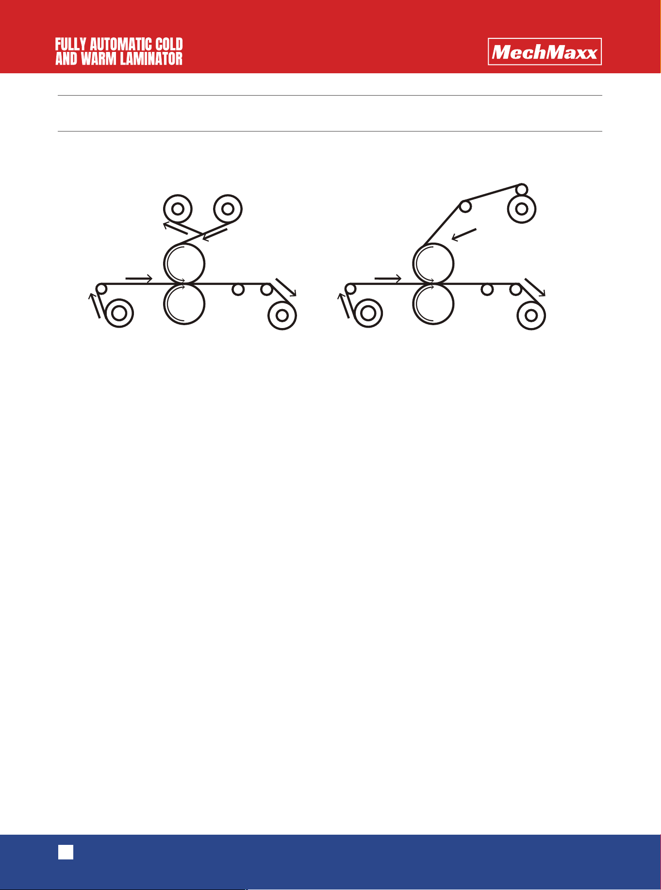
(5)According to the working sketch, peel off the film and lining, make the picture and film flat and fit, press the pneumatic
switch.
(6)Step on the foot switch and cover the film slowly. After a short distance, the finished product is taped onto the carton.
At the same time, the cutting knife is positioned. Continue to step on the foot switch and continue to cover the film.
(7)In the process of film-covering, we should carefully observe whether the film and the picture are arched. If the picture
is arched, we need to adjust the tension of the drawing mandrel. If the lining is rolled too slowly, we need to increase the
tension of the lining mandrel.
If there is a deviation in cutting, it can be adjusted by adjusting the knife to fine-tune the knob.
(8) When everything is normal, the foot control key is pressed again. When the foot control indicator lights are off, the
film can be covered continuously and the speed can be increased. When the coating is finished, press the stop button to
finish the operation and continue the coating of the next roll of materials.
WORKING SKETCH MAP
Picture Take-up shaft
Liner film laminating Bottomless film laminating
Picture Take-up shaft
Liner Film Aluminum pole
Aluminum pole
Bottomless film

INSTALLATION INSTRUCTIONS
FEEDBACK ON PROBLEMS
5
www.mechmaxx.com
(1)If the power switch is on, but the screen is not. Firstly, check whether the emergency stop switch is pressed. If it is
pressed, the machine will be out of power, which is one of the situations. If it is a problem with the emergency stop
switch, it is likely to be a problem with the controller, and the controller needs to be replaced.
(2)If there is a misalignment of the laminating, firstly check whether the sheet metal structure at both ends of the paint-
ing rod is tightly seamed with the fuselage, so there is a shift (with a gap), and the probability of misalignment will be
greatly increased. If it is not this problem, it is necessary to consider whether the aluminum rod of the screen and the
friction pads at both ends of the aluminum rod of the film are worn. If it is damaged, it needs to be replaced.
(3)If the backing paper is not collected in time, it is necessary to check whether the friction plate of the film rod and the
bottom paper rod is worn, which is basically the problem.
(4)If the finished product can't be collected , it is necessary to check whether the friction plate is worn and replaced
regularly.
(5)If the finished product was collected very quickly, which broke the picture, indicating that the finished product tight-
ened the device part, the shaft and sprocket were stuck, and the parts needed to be replaced.
(6)Put your hand directly in front of the roller, if the roller does not stop, mean the photoelectric switch is damaged and
needs to be replaced in time.
(7)For other questions, please contact the dealer or manufacturer.
1. Open the package. The list is as follows.
2.Remove the quartz tube gently.
3.Installing rack feet
4.Install oil-water separator.
5.Install the left and right brackets of the drawing mandrel. When installing the brackets, pay attention to the tightness
of the seams.
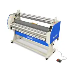
6.Install pedal switch.
7.Install quartz tube.
Drawing mandrel left bracket
Drawing mandrel right bracket
Frame foot
Quartz tube
Foot pedal
Screw bag
User manual
1
1
2
2
1
1
1
Left and right general
only needs one installation to prevent damage during transportation.
Name Quantity Remark

MAINTENANCE
6
www.mechmaxx.com
(1)Pay special attention : the rubber roller must not be scratched by hard objects or blades.
(2)Clean up the residual glue on the roller in time and keep clean.
(3)The maintenance of sprockets and chains requires regular lubrication.