III. Installation
(Figure 3-1) (Figure 3-2) (Figure 3-3)
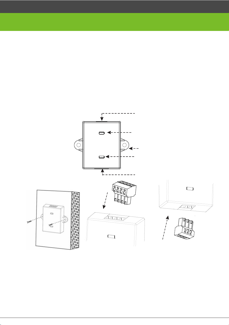
1. Fasten the SRB controller to the c e iling or wall (as shown in Figure 3-1).
2. Connect the access control terminal wit h the SRB controller (as shown in Figure 3-2)
3. Connect the lock with the SRB controller (as shown in Figure 3- 3)
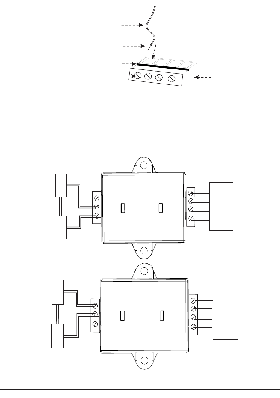
4. The connection between the cable and wiring terminal is shown in Figure 3-4. Insert
t h e exposed copper end of the wire into terminal hole to butt against the plastic
bottom from the top of sheet metal and fasten the screw to clamp the exposed
copper end.
3-pin output port
Green LED indicator
Fixing hole
Red LED indicator
4-pin input port
SRB Simple Access Controller Connection Guide
I. Electrical Parameters and Features
1. The SRB access controller works with th e access control function. After receiving the
Wiegand signals from the access control terminal, the SRB access controller outputs
relay signals to trigger the relay to unlock.
2. The input port of the SRB controller i s connected to the access control terminal to receive
the unlock/lock signals from it.
3. The output port of the SR B controller is connected to the lock to output unlock/lock
signals.
4. The input power (12V) supports reve r se polarity and over-voltage protection.
5. Both the input and output end s support the ESD protection function.
II. Appearance
12
V
IWD0
IWD1
GND
NO
COM
NC
1
(Figure 3-4)
IV. LED Indicator Status Description
After the SRB controller is connected with the 12V power supply, the red LED indicator is
on. After the correct Wiegand signals are input, the green LED indicator is on and the red
LED indicator is off at the same time. The LED indicator will be restored to its original
status in two seconds.
V. Definition of Terminal Block
Exposed copper
Sheet
Screw
Wiring Terminal
Power supply
Access
control
terminal
Power supply
Lock
Connection for unlock at power-on
Connection for unlock at power-off
Wire
(Strip the wire to expose a section of
copper core of 1-2 cm in length)
Lock
12V
WD 0
WD 1
12V
IWD 0
IWD 1
NO
+
+
-
-
COM
NC
GND
GND
12V
WD 0
WD 1
12V
IWD 0
IWD 1
NO
+
+
-
-
COM
NC
GND
GND
control
terminal
Access
2


