Pet-Immune PIR Detector
User Manual
Before using this device, carefully read and understand all
contents of this manual.Incorrect installation or use may lead to
device malfunction, false alarms, or failure to provide effective
protection.Retain this manual for future reference.Images are for
reference only; actual product features and appearance may vary.
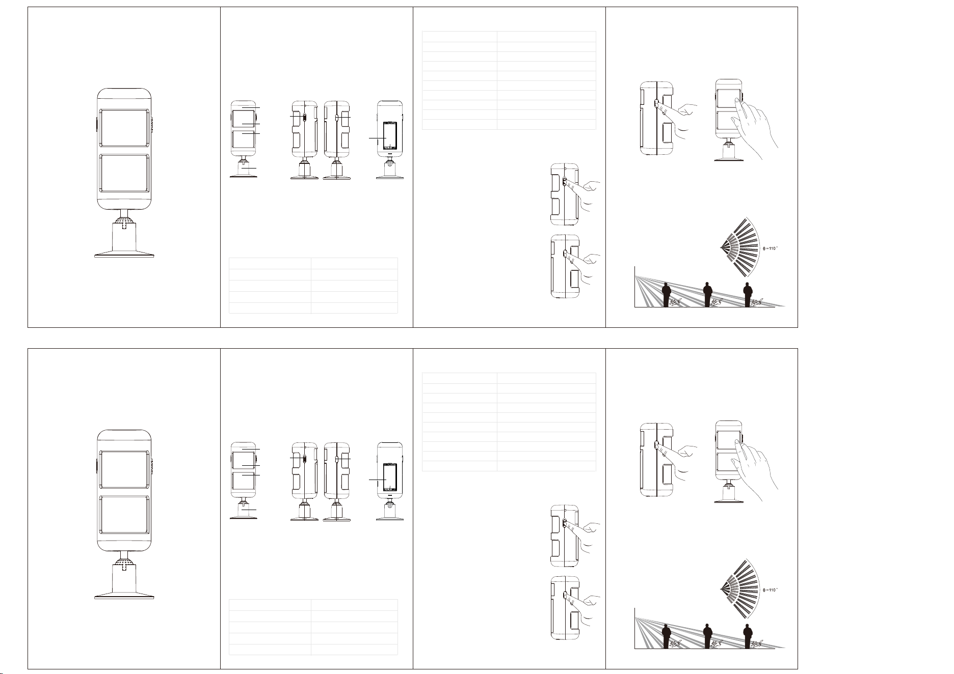
I. Product Overview II. Technical Specifications
III. Using the Infrared Detector
V. Installation & Calibration
IV. Pairing with Alarm Control Panel
1.1 Product Components Description
Indicator Light
Test Button
Detection
Window
Detection
Window
Power Switch
Mounting Bracket
Battery
Compartment
①Powering On the Device
• Slide the detector's Power Switch to ON.
• Normal Response: Red LED blinks
twice, confirming operational status.
• No Response? Open the Battery
Compartment and replace with new
batteries.
②Testing the Alarm
• Briefly press the Test Button once.
• Normal Response: Red LED blinks
once, indicating proper function.
• No Response? Open the Battery
Compartment and replace with new
batteries.
①Follow the Alarm Control Panel User Manual to
activate its Learning Mode for detectors.
② Place the detector near the control panel. Press the
Test Button or trigger motion directly in front of the
detector to transmit the pairing signal.
③ The detector and control panel will pair successfully.
NOTE:
• If the alarm control panel fails to pair with the detector
within 20 seconds, it will automatically exit pairing mode.
• Should pairing fail, repeat steps ① to ③ to retry the
process.
1.2 Visual Indicators
• Indicator Light: Displays the operating status of the detector.
• Detection Window: Receives human infrared radiation
for PIR detection.
• Mounting Bracket: Used for installing the detector.
• Test Button: For device testing and pairing operations.
• Power Switch: Turns the detector ON/OFF.
• Battery Compartment: Holds 2×AAA batteries.
Status
Power On
Test Alarm Triggered
Infrared Alarm Triggered
Low Battery
LED Indication
Red LED blinks 2 times
Red LED blinks 1 time
Red LED blinks 1 time
Red LED blinks 3 times
Operating Voltage
Standby Current
Alarm Current
Detection Range
Detection Angle
Transmission Freq.
Wireless Range
Operating Environment
Mounting Height
Pet Immunity
DC 3V (2×1.5V AAA batteries)
< 20 μA
< 25 mA
8~12 m
110°
433.92MHz (ASK)
> 100 m (open area)
-20℃~55℃, <95%RH
1.8 m ~ 2.2 m
≤25kg (55lbs)
Mounting Height
2m
Detection Range:8~12m PIR Coverage Diagram
This product employs two infrared detection sensors,
effectively resolving the issue of false alarms caused by
small pets. Simultaneously, it utilizes the operating principle
of dual infrared signal symmetry to significantly enhance
product stability. To ensure optimal performance, we
strongly recommend users thoroughly review the product
instruction manual.
Pet-Immune PIR Detector
User Manual
Before using this device, carefully read and understand all
contents of this manual.Incorrect installation or use may lead to
device malfunction, false alarms, or failure to provide effective
protection.Retain this manual for future reference.Images are for
reference only; actual product features and appearance may vary.
I. Product Overview II. Technical Specifications
III. Using the Infrared Detector
V. Installation & Calibration
IV. Pairing with Alarm Control Panel
1.1 Product Components Description
Indicator Light
Test Button
Detection
Window
Detection
Window
Power Switch
Mounting Bracket
Battery
Compartment
①Powering On the Device
• Slide the detector's Power Switch to ON.
• Normal Response: Red LED blinks
twice, confirming operational status.
• No Response? Open the Battery
Compartment and replace with new
batteries.
②Testing the Alarm
• Briefly press the Test Button once.
• Normal Response: Red LED blinks
once, indicating proper function.
• No Response? Open the Battery
Compartment and replace with new
batteries.
①Follow the Alarm Control Panel User Manual to
activate its Learning Mode for detectors.
② Place the detector near the control panel. Press the
Test Button or trigger motion directly in front of the
detector to transmit the pairing signal.
③ The detector and control panel will pair successfully.
NOTE:
• If the alarm control panel fails to pair with the detector
within 20 seconds, it will automatically exit pairing mode.
• Should pairing fail, repeat steps ① to ③ to retry the
process.
1.2 Visual Indicators
• Indicator Light: Displays the operating status of the detector.
• Detection Window: Receives human infrared radiation
for PIR detection.
• Mounting Bracket: Used for installing the detector.
• Test Button: For device testing and pairing operations.
• Power Switch: Turns the detector ON/OFF.
• Battery Compartment: Holds 2×AAA batteries.
Status
Power On
Test Alarm Triggered
Infrared Alarm Triggered
Low Battery
LED Indication
Red LED blinks 2 times
Red LED blinks 1 time
Red LED blinks 1 time
Red LED blinks 3 times
Operating Voltage
Standby Current
Alarm Current
Detection Range
Detection Angle
Transmission Freq.
Wireless Range
Operating Environment
Mounting Height
Pet Immunity
DC 3V (2×1.5V AAA batteries)
< 20 μA
< 25 mA
8~12 m
110°
433.92MHz (ASK)
> 100 m (open area)
-20℃~55℃, <95%RH
1.8 m ~ 2.2 m
≤25kg (55lbs)
Mounting Height
2m
Detection Range:8~12m PIR Coverage Diagram
This product employs two infrared detection sensors,
effectively resolving the issue of false alarms caused by
small pets. Simultaneously, it utilizes the operating principle
of dual infrared signal symmetry to significantly enhance
product stability. To ensure optimal performance, we
strongly recommend users thoroughly review the product
instruction manual.
VI.Battery Replacement
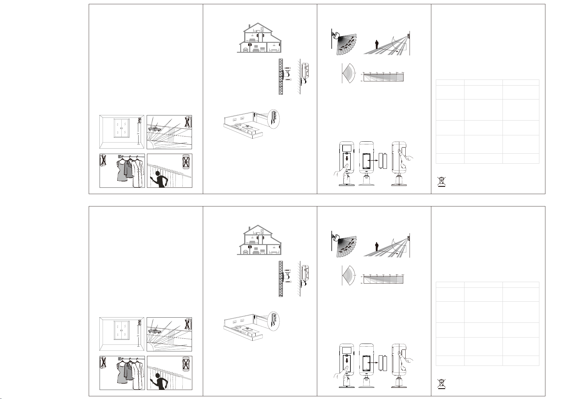
1. Installation Requirements
1.1 Optimal Motion Detection
Infrared detection sensitivity is highest when detecting
lateral movement relative to the sensor lens, while axial
movement (approaching/receding) yields reduced sensitivity.
Select installation locations accordingly.
1.2 Mounting Height
Installation height critically impacts both coverage range
and pet-immunity functionality. Recommended height:
Approximately 2 meters. (Fig. 1)
1.3 The detector should be avoided being directly facing the
sun, roads with heavy vehicle traffic, or other similar places.
(Fig. 2)
1.4 Within the protection range of the detector, there should
be no obstacles such as clothes or trees in its direct line of
sight. (Fig. 3)
1.5 The detector should not be directed at objects with
reflective properties such as metal walls or glass. (Fig. 4)
1.6 The wall where the detector is installed should be stable
without shaking, and the installed detector should not wobble.
2. Installation & Calibration
2.1 Recommended Locations
Install in vulnerable entry points:
2.2 Mounting Procedure
• Secure the mounting bracket at
~2m height using self-tapping screws.
• Align the detector's grooves with
the bracket and snap into place.
When the battery power is low, the red LED of the detector
will flash quickly three times and send a low-battery alarm to
your alarm control panel to remind you to replace the battery.
How to replace the battery:
① Remove the back cover and open the battery compartment.
② Take out the old batteries and replace them with new
ones of the same type (2 AAA batteries).
③ Close the battery compartment cover and test whether
the detector works normally.
2.3 Angle Adjustment
Maintain vertical installation (detector-to-bracket
angle ≤0°) for optimal pet-immunity performance.
2.4 Walking Test
1)Turn on the power switch on the side of the detector. The
red LED will flash twice and then turn off, indicating that it
has entered the detection state.
2)When a person moves horizontally at a normal walking
speed (0.7m/s) within the detection area, 8 meters away
from the detector, an alarm should be triggered within 8
meters (i.e., the alarm indicator light turns on), which means
the installation is normal. If not, you must adjust the vertical
angle of the detector and perform debugging according to
the above test method until the test result is normal.
2.5 Detection Range
VII.Maintenance
1.Do not touch the surface of the infrared sensor or the filter
lens with hands or other objects, as this may affect the
sensitivity of the detector. If it is necessary to clean the
sensor or filter lens, disconnect the power first and wipe them
with a dust-free cloth dipped in a small amount of alcohol.
2.Regular walking tests should be conducted on the detector.
Warning: As a high-tech product, this detector can effectively
reduce the occurrence of theft incidents, but it cannot
guarantee absolute safety. For your safety, in addition to
using this product correctly, you should also stay alert in
daily life and strengthen your safety awareness.
VIII.Troubleshooting
2m
Detector
Fig. 1 Fig. 2
Fig. 3 Fig. 4
study
Bedroom
Bedroom
KitchenGarage Living Room
① ②
① ② ③
Top View Side View
AAA
batteries
Environmental Protection
角度≤0°
垂直安装
Note: The horizontal direction is mainly used to adjust the
detection area, while the vertical direction is mainly used to
adjust the sensitivity and detection distance. It is
recommended to perform a walking test every 3 months.
Problem Cause Solution
Power ON the
device with no
response.
Battery depletion or
incorrect installation
detected.
Reinstall existing
batteries or replace
with new ones.
A false alarm
Occurs.
Incorrect
installation.
Adjust the
installation location
and mounting angle.
The red LED
blinks
periodically
three times.
Reduced
wireless range
The battery level
is low.
Replace the
batteries.
The battery level
is low.
Replace the
batteries.
The device
does not
respond when
the Test button
is pressed.
The batteries have
run out.
Replace the
batteries.
Waste electrical products should not be disposed
of with household waste.Please recycle where
facilities exist.Check with Local Authority or retailer
for recycling advice.
VI.Battery Replacement
1. Installation Requirements
1.1 Optimal Motion Detection
Infrared detection sensitivity is highest when detecting
lateral movement relative to the sensor lens, while axial
movement (approaching/receding) yields reduced sensitivity.
Select installation locations accordingly.
1.2 Mounting Height
Installation height critically impacts both coverage range
and pet-immunity functionality. Recommended height:
Approximately 2 meters. (Fig. 1)
1.3 The detector should be avoided being directly facing the
sun, roads with heavy vehicle traffic, or other similar places.
(Fig. 2)
1.4 Within the protection range of the detector, there should
be no obstacles such as clothes or trees in its direct line of
sight. (Fig. 3)
1.5 The detector should not be directed at objects with
reflective properties such as metal walls or glass. (Fig. 4)
1.6 The wall where the detector is installed should be stable
without shaking, and the installed detector should not wobble.
2. Installation & Calibration
2.1 Recommended Locations
Install in vulnerable entry points:
2.2 Mounting Procedure
• Secure the mounting bracket at
~2m height using self-tapping screws.
• Align the detector's grooves with
the bracket and snap into place.
When the battery power is low, the red LED of the detector
will flash quickly three times and send a low-battery alarm to
your alarm control panel to remind you to replace the battery.
How to replace the battery:
① Remove the back cover and open the battery compartment.
② Take out the old batteries and replace them with new
ones of the same type (2 AAA batteries).
③ Close the battery compartment cover and test whether
the detector works normally.
2.3 Angle Adjustment
Maintain vertical installation (detector-to-bracket
angle ≤0°) for optimal pet-immunity performance.
2.4 Walking Test
1)Turn on the power switch on the side of the detector. The
red LED will flash twice and then turn off, indicating that it
has entered the detection state.
2)When a person moves horizontally at a normal walking
speed (0.7m/s) within the detection area, 8 meters away
from the detector, an alarm should be triggered within 8
meters (i.e., the alarm indicator light turns on), which means
the installation is normal. If not, you must adjust the vertical
angle of the detector and perform debugging according to
the above test method until the test result is normal.
2.5 Detection Range
VII.Maintenance
1.Do not touch the surface of the infrared sensor or the filter
lens with hands or other objects, as this may affect the
sensitivity of the detector. If it is necessary to clean the
sensor or filter lens, disconnect the power first and wipe them
with a dust-free cloth dipped in a small amount of alcohol.
2.Regular walking tests should be conducted on the detector.
Warning: As a high-tech product, this detector can effectively
reduce the occurrence of theft incidents, but it cannot
guarantee absolute safety. For your safety, in addition to
using this product correctly, you should also stay alert in
daily life and strengthen your safety awareness.
VIII.Troubleshooting
2m
Detector
Fig. 1 Fig. 2
Fig. 3 Fig. 4
study
Bedroom
Bedroom
KitchenGarage Living Room
① ②
① ② ③
Top View Side View
AAA
batteries
Environmental Protection
角度≤0°
垂直安装
Note: The horizontal direction is mainly used to adjust the
detection area, while the vertical direction is mainly used to
adjust the sensitivity and detection distance. It is
recommended to perform a walking test every 3 months.
Problem Cause Solution
Power ON the
device with no
response.
Battery depletion or
incorrect installation
detected.
Reinstall existing
batteries or replace
with new ones.
A false alarm
Occurs.
Incorrect
installation.
Adjust the
installation location
and mounting angle.
The red LED
blinks
periodically
three times.
Reduced
wireless range
The battery level
is low.
Replace the
batteries.
The battery level
is low.
Replace the
batteries.
The device
does not
respond when
the Test button
is pressed.
The batteries have
run out.
Replace the
batteries.
Waste electrical products should not be disposed
of with household waste.Please recycle where
facilities exist.Check with Local Authority or retailer
for recycling advice.
§ 15.19 Labelling requirements.
This device complies with part 15 of the FCC Rules. Operation is subject to the following two
conditions:(1) This device may not cause harmful
interference, and (2) this device must accept any interference received, including interference
that may cause undesired operation.
§ 15.21 Information to user.
Any Changes or modifications not expressly approved by the party responsible for compliance
could void the user's authority to operate the
equipment.
§ 15.105 Information to the user.
Note: This equipment has been tested and found to comply with the limits for a Class B digital
device, pursuant to part 15 of the FCC Rules. These
limits are designed to provide reasonable protection against harmful interference in a
residential installation. This equipment generates uses and can radiate radio frequency energy
and, if not installed and used in accordance with the instructions, may cause harmful
interference to radio
communications. However, there is no guarantee that interference will not occur in a
particular installation. If this equipment does cause harmful
interference to radio or television reception, which can be determined by turning the
equipment off and on, the user is encouraged to try to correct
the interference by one or more of the following measures:
-Reorient or relocate the receiving antenna.
-Increase the separation between the equipment and receiver.
-Connect the equipment into an outlet on a circuit different from that to which the receiver is
connected. -Consult the dealer or an experienced radio/TV technician for help.