1.4 Remote Operation
1. Viewing Alarm Sound Files
1) Turn off the alarm’s battery power switch.
IV. How to View and Replace Alarm Sounds
III. Accessory Configuration
Solar Alarm User's Manual
I. Product Overview
Pictures are for reference only; please refer to the actual product.
(Optional)
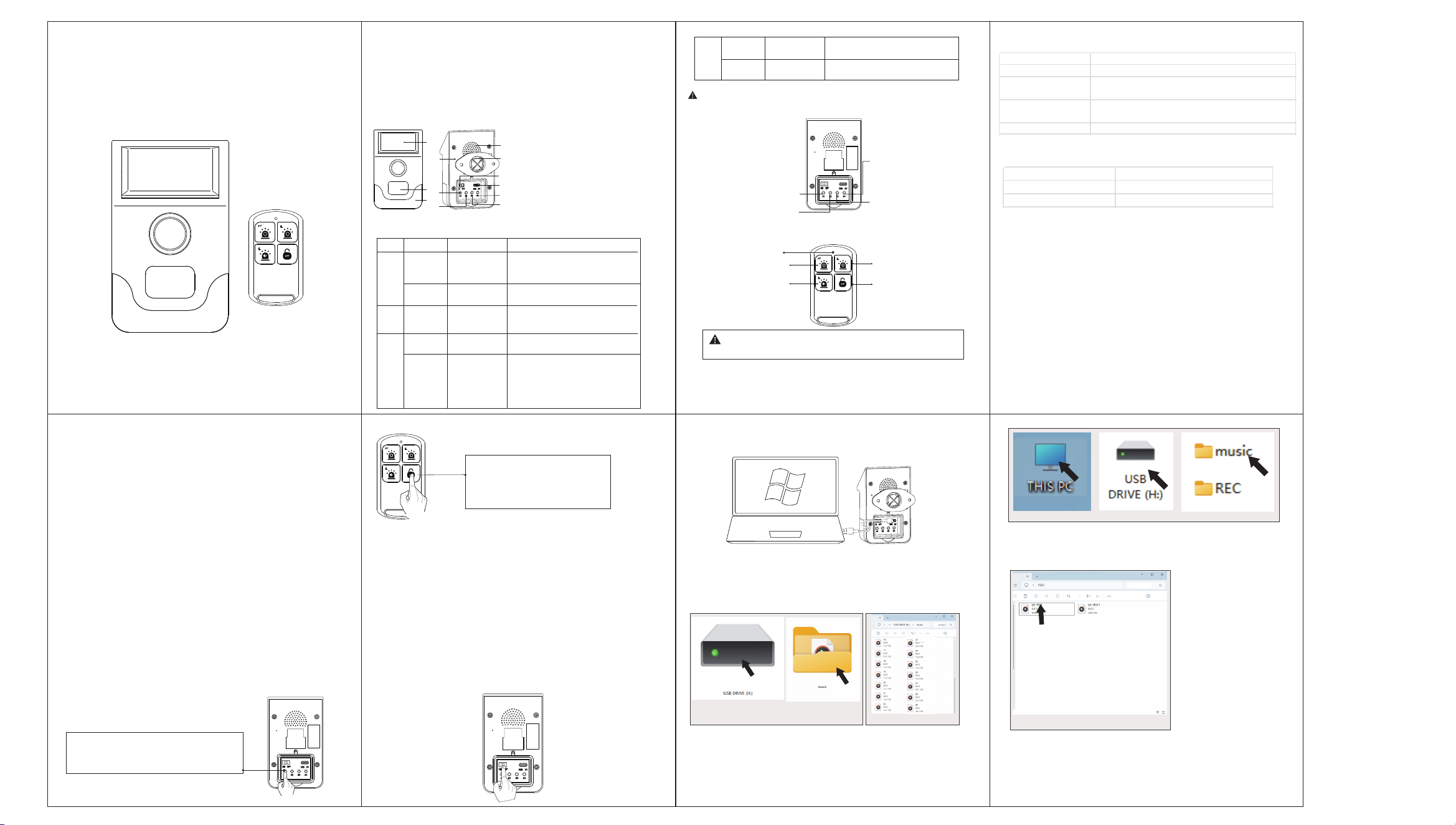
1.1 Product Functional Diagram
1.3 Operation View
II. First T
ime Use
1. Powering On the Alarm
1)Open the waterproof cover on the back of the alarm. Slide the battery
power switch to the ON position to supply power to the device.
2. Infrared Sensor Test
After power-on, wave your hand in front of the infrared detection
window. The alarm will immediately trigger with both sound and light
upon detection.
3. Set Playback Times
Long press the S3 key to cycle through playback times: 3 times / 5 times
/ 10 times / 15 times (default: 3 times).
6.Recording and Playback
1) Preparation: Open the waterproof cover on the back of the alarm
and slide the battery power switch to the ON position.
2.)Start: Press and hold button S4. After hearing the " start Recording"
prompt, speak towards the microphone to record (max. 30 seconds).
3)Stop: Release button S4. The recording will be saved automatically.
4)Playback: Press button S4 briefly to play the last recording.
A single alarm unit supports pairing with up to 10 remote controls. To
control multiple alarms with one remote, please pair them using the
following procedure.
①Short press the S1 button, the indicator
light will flash continuously, and the
Speaker will play "Sensor pairing mode.
2) Connect one end of a Type-C USB cableto the alarm’s USB port
and the other end to a computer’s USB port.
3.1 Pairing the Alarm with the Remote Control
3.2 Pairing the Alarm with the Alarm Control Panel
3) On the computer, double-click "This PC" to locate a "USB Drive".
4) Double-click the "USB Drive" to open it. You will see two folders:
"music" and "REC". the "music" folder contains alarm sound files.
the "REC" folder contains recorded audio files. Double-click the
"music" folder to view the alarm sound files.
① ③②
①
②
③
② Press any key on the remote
control within a range of less than
5m. After successful pairing,
the buzzer will beep once.
4. Accessory Pairing Mode
Entering: After power-on, briefly press S1 to enter a 20-second pairing
mode. The mode will exit automatically upon timeout.
Exiting: Press any button during the process to exit immediately.
Note: This method also applies for quick exit if you accidentally enter
the pairing mode.
5.Setting the Working Mode and Alarm Tone
1)Press S2 briefly to switch the Working mode.
2)Press S3 briefly to set the alarm tone.
2.Replace the Alarm Sound
1)Turn off the alarm's battery power switch, connect one end of a
Type-C USB data cable to the alarm's USB port, and the other end to a
computer's USB port (as in the "Viewing Alarm Sound Files" operation).
On the computer, open the following in sequence: This PC → USB Drive
→ "music" folder (see the figure below).
① Rename the MP3 file to "18"
1. Solar Charging Panel
2. Infrared Window
3. Indicator Light
4. Microphone
5. Learning/Factory Reset Button
6. Work Mode Switch
7. Speaker Sound Outlet
8. Mounting Bracket
9. Battery Power Switch
10. Type-C Port
11. Record/Playback Function
12.Switch alarm sound / Playback times
2
3
1
8
7
5
10
11
9
12
4
6
This outdoor solar alarm combines solar charging, custom recording, and
quick-control operation into one integrated system. With excellent
anti-interference capabilities, it effectively prevents false alarms and missed
detections. The product is widely suitable for various outdoor security
applications including homes, farms, orchards, factories, warehouses, and
perimeter protection, providing reliable 24/7 warning protection.
1.2 Button Functions Description
Warning: The device must not be powered off immediately after
operation, as this may terminate the data saving process abnormally.
S1: Short press to pair
accessory,long press to
restore factory settings.
S4: Short press to play
recording. Long press to
start recording, release
to stop.
S3: Short press to cycle
through alarm sounds,
long press to switch
playback times.
S2: Short press to cycle
through working modes.
Led Light
Mode 1: 24 hours
sound and light
Mode 3: Night flash mode
Mode 2: Night sound
and light mode
Mode 4: Close the alarm
Note: When the alarm is turned off, the device will stop all
sensor functions. To reactivate it, briefly press the S2 button
or use the remote control to set a working mode.
1.5 Working Mode Description
Working Mode Status Description
24-hr Sound & Light Triggers Sound and Light alarm upon detection, 24/7.
Night sound & light
Mode
The device sleeps during daytime, triggers audible and
visual alarm at night.
Night Flash Mode
Triggers Sound and Light alarm during daytime, Light
(flash) alarm only at night.
Close the Alarm Disables detection function; device enters standby state.
1.6 USB Port Function Description
Function Description
Charging Provides power to the alarm
Data Management Read and replace alarm sound files
1) Set Up the Control Panel Follow the instructions in the control panel's
manual to set it to "Accessory Pairing" mode.
2) Power On the Alarm and Initiate Pairing
i. Power on the alarm: Open the waterproof cover on its back and slide
the battery switch to the ON position.
ii. Trigger the signal: Immediately after power-on, wave your hand in
front of the infrared detection window. The alarm will transmit a wireless
pairing signal.
3) Confirm Pairing Result: A successful pairing will be confirmed by the
control panel via a message, sound, or indicator light flash.
S4
Short
press
Long
press
Play
recording
Indicator flashes + Plays the
recorded audio
Indicator stays lit + Voice
prompt: "Start recording"
Start
recording
Button
S1
Operation
Short
press
Long
press
Main Function
Learn
accessory
Indicator flashes + Voice prompt:
"Entered accessory learning mode,
please trigger the accessory"
Indicator flashes 4 times + Voice
prompt: "Factory reset successful"
Restore factory
settings
S2
Short
press
Switch
working
mode
Indicator flashes 1–4 times
(corresponding to mode) +
Voice announces current mode
S3
Short
press
Long
press
Switch alarm
sound
Indicator flashes once + Plays
current alarm sound
Indicator flash count / prompt
tone count corresponds to:
3 times: flash 1 / beep 1
5 times: flash 2 / beep 2
10 times: flash 3 / beep 3
15 times: flash 4 / beep 4
Switch
playback
times
Audio & Visual Feedback
2)Rename
①Rename the alarm sound file of the new MP3 format to any
number from 18 to 33.For example, name the audio file as 18.
3)Replace the Alarm Sound
① Copy the sound file renamed as 18 to the music folder, replacing the
original alarm sound file.
Power Supply
Alarm Sound Level
Charging Time
Detection Angle
Detection Range
Battery Parameter
Transmit/Receive Frequency
Remote Control Range
Control Panel Reception Range
Operating Temperature
Working Humidity
IP Rating
Dimension
WARNING:
Do not use other adapters with higher voltages,otherwise
it will damage the product and dangerous!
Important Notice: When the battery voltage of the alarm is too
low, the indicator light will flash three times as a low-battery alert,
after which the device will stop operating. Please charge it in a
timely manner!!
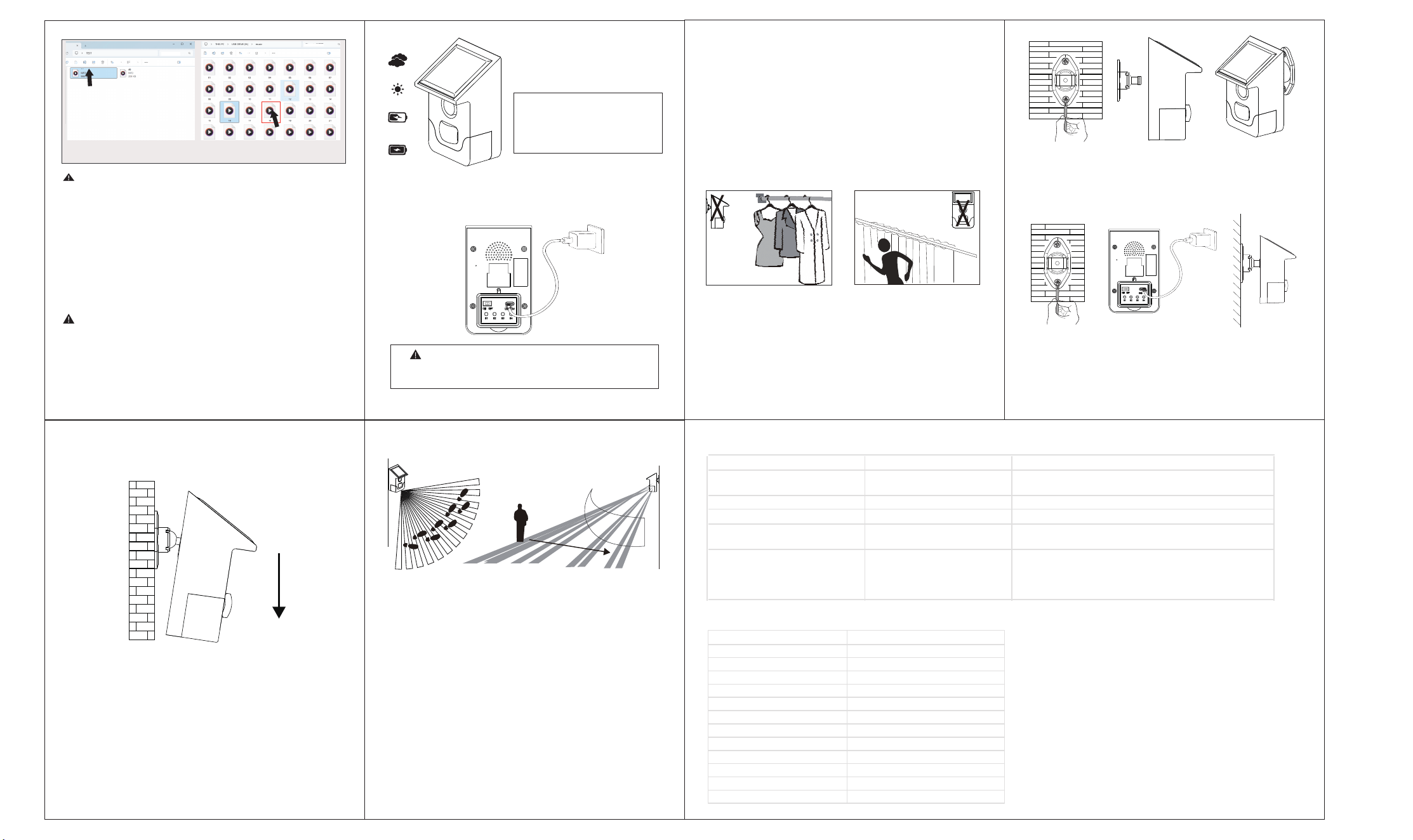
1. Solar Charging
Install the alarm in a location with strong sunlight exposure for
solar charging, as shown:
V. Charging Instructions
1. Installation Requirements
1.1 The alarm achieves highest sensitivity when detecting lateral
movement across its sensor window. Sensitivity decreases for
movement directly toward/away from the unit. Select installation
location accordingly.
1.2 Maintain a direct line of sight to protected areas without
obstructions (clothing, trees, etc.). (Fig.1)
1.3 MUST NOT be directed toward reflective surfaces (e.g., metal
walls, glass). (Fig.2)
1.4 Mount on stable, vibration-free surfaces. Installed unit must
remain rigid.
2. Installation & Adjustment
2.1 Location: Install at potential entry points.
2.2 Installation Procedure
2.2.1 Outdoor Installation
Secure mounting bracket at ~2m height using self-tapping screws.
Align alarm’s rear slots with bracket and snap into place.
2.3 Angle Adjustment
Optimize detection coverage by tilting the alarm vertically/horizontally.
2.4 Walk Test
Enable battery power switch to activate detection mode.Walk laterally
across detection zone at 0.7m/s from 8m distance.
Correct installation: Triggers audible/visual alarm within 8m range.
If no alarm: Adjust vertical angle and retest until successful.
Note:
1)Horizontal adjustment: Modifies detection area coverage.
2)Vertical adjustment: Controls sensitivity/detection range.
3)Perform walk tests quarterly.
2.Regular walking tests should be conducted on the detector.
Warning: As a high-tech product, this alarm can effectively reduce the
occurrence of theft accidents, but it cannot guarantee absolute safety.
For your safety, in addition to using this product correctly, you should
also stay alert in daily life and enhance your safety awareness.
VI. Solar Alarm Installation
VII. Maintenance
VIII. Troubleshooting
IX. Technical Specifications
Fig.1 Fig.2
Solar Alarm
2.2.2 Indoor Installation
Secure mounting bracket at ~2m height using self-tapping screws.
Connect alarm to USB DC5V power source.
Align alarm’s rear slots with bracket and snap into place.
2. Power Adapter Charging
Charge the alarm using a USB-DC 5V/1A adapter, as shown:
③
1.Do not touch the surface of the infrared sensor or the filter lens with
hands or other objects, as this may affect the sensitivity of the detector.
If it is necessary to clean the sensor or filter lens, disconnect the power
supply first and wipe with a dust-free cloth dipped in a small amount
of alcohol.
① ② ③
① ② ③
Notes:
1.Among the audio files in the music folder, those numbered 18–33 are
alarm prompt sounds and can be customized and replaced. Other
numbered files are operation prompt sounds, which are closely related
to system functions. Do not modify them arbitrarily to avoid affecting
normal use.
2.The maximum replaceable alarm sound files are MP3 format files within
the USB drive's capacity.
3.When the alarm is connected to a USB data cable, it remains in normal
detection mode. During the process of reading or replacing alarm sound
files, the alarm's indicator light will flash, which is a normal phenomenon.
①Copy the new sound file that
has been renamed to "18"
②Into the "music" folder to replace
the original alarm sound file.
18
Note: Different weather and
seasonal light intensity can affect
charging efficiency, The installation
position should meet the direct
sunlight over 5hrs at least.
Problem Cause Solution
Alarm unresponsive when battery
switch is turned on
Battery depleted Charge the alarm
No response when pressing buttons Battery depleted Charge the alarm
False alarms triggered Improper installation Adjust installation position and angle
The alarm has no response when
the remote control is pressed
The remote has been unpaired/
disconnected from the alarm
Repair according to the chapters of "Accessory Configuration"
and "Pairing the Alarm with the Remote Control"
The alarm is triggering an alert,
but the alarm control panel
shows no response
1.The alarm and the alarm host
are not paired
2.The distance between the alarm
and the alarm host is too far
1.Re-pair according to the chapters "Accessory Configuration"
and "Pairing the Alarm with the alarm control panel"
2.Please ensure that the wireless distance between the alarm
and the alarm control panel is within the specified range
Solar charging/DC 5V
≥100dB
Solar:>10 hours, USB:2 hours
110°
8–12m
DC 3.7V/500mAh lithium battery
433.9MHz / ASK
≥100 meters (open area)
≥100 meters (open area)
-20℃ ~ 55℃
≤95%RH (no condensation)
IP54
118.5x72x62mm

§
15.19 Labelling requirements.
This device complies with part 15 of the FCC Rules. Operation is subject to the following two
conditions:(1) This device may not cause harmful
interference, and (2) this device must accept any interference received, including interference
that may cause undesired operation.
§
15.21 Information to user.
Any Changes or modifications not expressly approved by the party responsible for compliance
could void the user's authority to operate the
equipment.
§
15.105 Information to the user.
Note: This equipment has been tested and found to comply with the limits for a Class B digital
device, pursuant to part 15 of the FCC Rules. These
limits are designed to provide reasonable protection against harmful interference in a
residential installation. This equipment generates uses and can radiate radio frequency energy
and, if not installed and used in accordance with the instructions, may cause harmful
interference to radio
communications. However, there is no guarantee that interference will not occur in a
particular installation. If this equipment does cause harmful
interference to radio or television reception, which can be determined by turning the
equipment off and on, the user is encouraged to try to correct
the interference by one or more of the
following measures:
-Reorient or relocate the receiving antenna.
-Increase the separation between the equipment and receiver.
-Connect the equipment into an outlet on a circuit different from that to which the receiver is
connected. -Consult the dealer or an experienced radio/TV technician for help.
* RF warning for Portable device:
The device has been evaluated to meet general RF exposure requirement. The device can be
used in portable exposure condition without restriction.