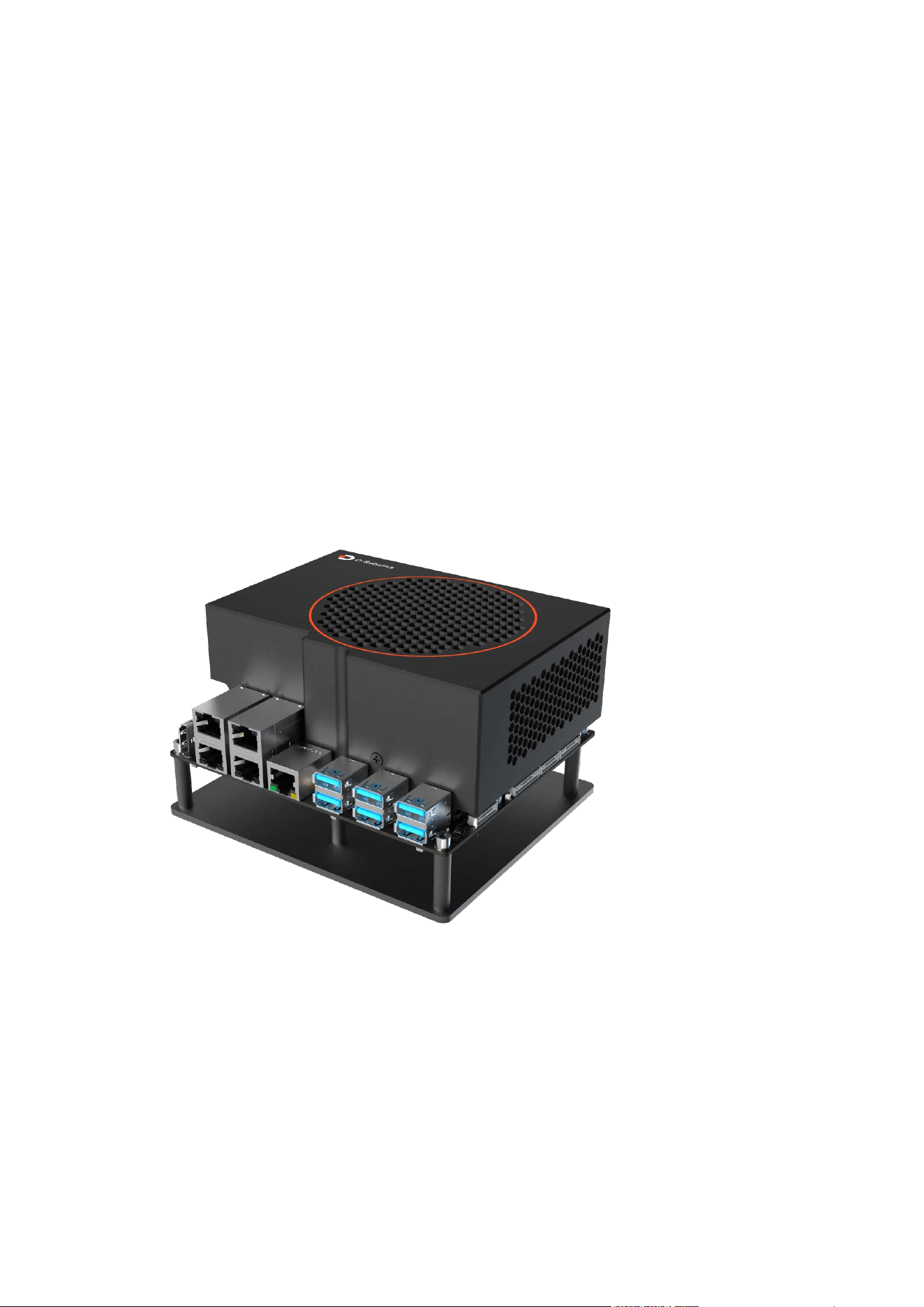
D-Robotics RDK Kit
This document serves as the user manual for the D-Robotics RDK Kit Super series,
providing developers with usage instructions and development guidance for products
such as the RDK S600. The content covers multiple aspects including hardware design,
system customization, application development, and algorithm toolchains.
Product Introduction
The RDK S600 Series is a high-performance development kit featuring 560 TOPS of
on-device AI inference capability and a 18-core ARM Cortex-A78AE processor. It supports
six MIPI camera inputs, six USB 3.0 ports, and four PCIe 3.0 interfaces, fully meeting the
requirements of various application scenarios.
Quick Start
1.1 Hardware Introduction
1.1 Developer Kit
Product Introduction

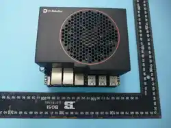
The D-Robotics RDK S600 Series Developer Kit is equipped with the S600 intelligent
computing chip, with the BPU providing up to 560 TOPS of computing power. It is a
development board designed for intelligent computing and robotics applications,
featuring rich interfaces and extreme ease of use. Its unique heterogeneous design can
simultaneously handle perception inference and real-time motion control needs, reducing
the volume and complexity of the control system.
Key Specifications
Category
Specifications
CPU
• 18x Arm® Cortex®-A78AE CPU 2.0GHz
MCU
• 6x Arm® Cortex®-R52+ MCU (1× DCLS, 2× Split-Lock)
BPU
• 4x BPU Nash core provides up to 560 TOPS
Memory
• 32/64GB LPDDR5, 256-bit, up to 6400MT/s
Storage
• 64/256GB UFS 3.1
• M.2 Key M Connector for NVMe SSD
USB
• 6x USB 3.2 Gen 1x1 Type-A
• 1x USB 2.0 Type-C (for flashing and debugging)
Network
• M.2 Key E Connector for Wi-Fi&BT Module
• 2x 1GbE RJ45 Ports
• 2x 10GbE RJ45 Ports
• 1x 1GbE RJ45 Ports (MCU-Domain)
Display
• 1x HDMI
Expansion
• 2x Camera Expansion Connector
• 1x MCU Port Expansion Connector
Connectors
• 1x 2-pin RTC Battery Connector
• 1x 4-pin Fan Connector
• 1x 12-pin Automotive Connector
• 1x JTAG Debug Connector (for Main and MCU)
• 1x 12-pin MCU-Domain CAN(5x) Connector
• 1x 10-pin Main-Domain CAN(4x) Connector

Category
Specifications
• 1x 10-pin MCU-Domain UART(2x) & Main-Domain UART(2x) Connector
• 1x 10-pin PCM Connector
• 2x 22-pin MIPI Connector
Power
• 12~28V
• 4-pin Connector
Size
• 140mm x 123mm x 78mm
Model Description
Product Name
Model
Memory
Storage
Notes
RDK S600 32G
KS6X032064C
32GB LPDDR5
64GB UFS
Official Model
RDK S600 64G
KS6X064256C
64GB LPDDR5
256GB UFS
Official Model

Inter
face Description
Interface Definition: D-Robotics_RDK_S600_Connector_Application_Note_V1P0.xlsx
FCC Compliance Notice
This device complies with part 15 of the FCC Rules. Operation is subject to the following two conditions:
(1) This device may not cause harmful interference, and
(2) this device must accept any interference received, including interference that may cause undesired
operation.
Any changes or modifications not expressly approved by the party responsible for compliance could void
the user's authority to operate the equipment.
This equipment has been tested and found to comply with the limits for a Class B digital device, pursuant
to part 15 of the FCC Rules. These limits are designed to provide reasonable protection against harmful
interference in a residential installation. This equipment generates, uses and can radiate radio frequency
energy and, if not installed and used in accordance with the instructions, may cause harmful interference
to radio communications. However, there is no guarantee that interference will not occur in a particular
installation. If this equipment does cause harmful interference to radio or television reception, which can
be determined by turning the equipment off and on, the user is encouraged to try to correct the
interference by one or more of the following measures:
‐
Reorient or relocate the receiving antenna.
‐Increase the separation between the equipment and receiver.
‐Connect the equipment into an outlet on a circuit different from that to which the receiver is connected.
‐Consult the dealer or an experienced radio/TV technician for help.
FCC Radiation Exposure Statement
This equipment complies with FCC radiation exposure limits set forth for an uncontrolled environment .
This transmitter must not be co-located or operating in conjunction with any other antenna or transmitter.
This equipment should be installed and operated with minimum distance 20cm between the radiator& your
body.

Main Board Power Interface (J1)
NOTE
The RDK S600 Developer Kit supports 12V-28V power supply, with a maximum current of
16A, using a 4-pin Microfit Connector.
D-Robotics provides a power adapter with a rated output voltage of 24V and a maximum
output current of 8A.
699-Pin B2B Connector (J2)
The RDK S600 Developer Kit provides a 699-pin connector for connecting to the RDK S600
Compute Module.
NOTE
To use the 699-Pin B2B Connector, please contact FAE in advance for more detailed
information.
JTAG Interface MCU&MAIN (J3)
The RDK S600 Developer Kit provides a 10-pin connector for JTAG debugging of the RDK
S600 Compute Module's MCU.
Flash, Main&MCU Debug (J4)
The USB Type-C (J16) is used only for flashing and debugging. It is not a standard
full-featured USB Type-C port and includes the following functions:
•
Debug Serial Port. Hardware-wise, two CH340 chips convert the debug serial ports of the
Main domain and MCU domain of the compute module into USB interfaces. Users can use
this interface for various debugging tasks. The first time you use this interface, you need
to install the CH340 driver on your computer. You can search for the keyword CH340 serial

driver to download and install it. The parameters of the computer's serial tool need to be
configured as follows:
•
o Baud rate: 921600
o Data bits: 8
o Parity: None
o Stop bits: 1
o Flow Control: None
•
USB Download Interface. The download interface provided by the RDK S600 development
board is used for firmware download. For details, please refer to 1.2 System Flashing
•
NOTE
The USB Type-C port provided by the RDK S600 Developer Kit only supports Device mode.
M.2 Key E Interface (J5)
Default configuration for connecting a PCIe Wi-Fi and USB 2.0 BT module, also supports
UART 4-wire BT modules. PCIe supports Gen3x1. Also provides SDIO interface, PCM audio
interface, no LED or ALERT signals.
NOTE
1. If support for Wi-Fi/Bluetooth sleep/wake-up of the S600 is required, please contact
D-Robotics engineers for support.
2. When the system is in light sleep and deep sleep modes, the VDD_AON_PERI_3V3 power
supply remains on, with a maximum supply current of 750mA.
M.2 Key M Interface (J6)

Used for connecting a PCIe solid-state drive (SSD), supports Gen4x2, has an ALERT signal,
no LED signal.
NOTE
Sleep/wake-up functionality is not supported.
NOTE
When the system is in light sleep and deep sleep modes, the VDD_PERI_3V3 power supply
is turned off, with a maximum supply current of 700mA.
USB 3.0 Type-A Interface (J7/J8/J9)
The RDK S600 development board provides six USB 3.0 standard interfaces extended via
PCIe, capable of supporting six USB peripherals simultaneously. Each USB 3.0 interface
supports a maximum output power of 5V/1A.
NOTE
• The USB 3.0 interfaces provided by the RDK S600 development board only support Host
mode.
• Pay attention to USB 2.0 Camera Access Limitations.
HDMI Interface (J10)
The RDK S600 Developer Kit provides one HDMI display interface, supporting display
modes up to 2k at 60 frames per second. Upon power-on, the developer kit outputs the
Ubuntu graphical interface via the HDMI interface. With specific example programs, it also
supports preview display of camera and video stream feeds.
MIPI Camera Interface (J11/J13)

The RDK S600 includes 2 camera expansion interfaces, which can be used to connect
monocular or binocular cameras. Each MIPI camera interface provides 1 MIPI DPHY, 1 IIC,
and 1 3.3V power supply. See Interface Description
for MIPI camera interface signal
definitions.
NOTE
• IIC level standard is 3.3V.
• Maximum current for the 3.3V supply is 1A.
Camera Expansion Interface (J12/J14)
The RDK S600 Developer Kit includes 2 camera expansion interfaces. The camera
expansion interface uses an 80-pin board-to-board connector. Each camera expansion
interface can provide the following functions. See Interface Description
for camera
expansion interface signal definitions.
• 2x D-PHY or configurable to 1x D-PHY + 1x C-PHY.
• 2x IIC interfaces.
• 4x PWM signals for camera triggering.
• 2x sensor error signals.
• 2x deserializer lock signals.
• 2x deserializer error signals.
• 2x deserializer PWRON signals.
• 2x POC EN signals.
• 2x POC INT signals.
• 12V power supply, max 2A.
• 3.3V power supply, max 1A.
• 1.8V power supply, max 50mA, used for signal pull-up/pull-down.
NOTE
The maximum power supply capability for 12V is 2A, please pay attention to the total
power consumption of the sensors used.

MCU Expansion Interface (J15)
The RDK S600 Developer Kit includes an 80-Pin expansion interface, referred to as the
MCU 80-Pin Connector.
• Power signals: VDD_MCU_PERI_5V, VDD_MCU_PERI_3V3, VDDIO_MCU_3V3,
VDDIO_MCU_1V8
• Communication interfaces:
o I2C13, configured with an equivalent 2.2K pull-up resistor on the mainboard.
o I2C14, configured with an equivalent 2.2K pull-up resistor on the mainboard.
o SPI4, SPI6, SPI8, SPI13.
• CAN interfaces: CAN1, CAN2, CAN3, CAN4, CAN10
• Other signals: GPIO, PWM, ADC, PPS signal
NOTE
1. The MCU 80-Pin Connector includes IOs with both 1.8V and 3.3V logic levels. For detailed
information, please refer to Interface Description.
2. When the system is in light sleep, the VDD_MCU_PERI_5V and VDD_MCU_PERI_3V3 power
supplies remain on, with a maximum supply current of 1000mA each.
3. When the system is in deep sleep, the VDD_MCU_PERI_5V and VDD_MCU_PERI_3V3 power
supplies are turned off.
4. VDDIO_MCU_3V3 and VDDIO_MCU_1V8 have a maximum supply current of 50mA each,
suitable only for low-power applications such as level shifting, pull-up/down resistors,
ADC voltage dividers, etc. When the system is in light sleep mode, VDDIO_MCU_3V3 and
VDDIO_MCU_1V8 remain on. When the system is in deep sleep mode, VDDIO_MCU_3V3
and VDDIO_MCU_1V8 are turned off.
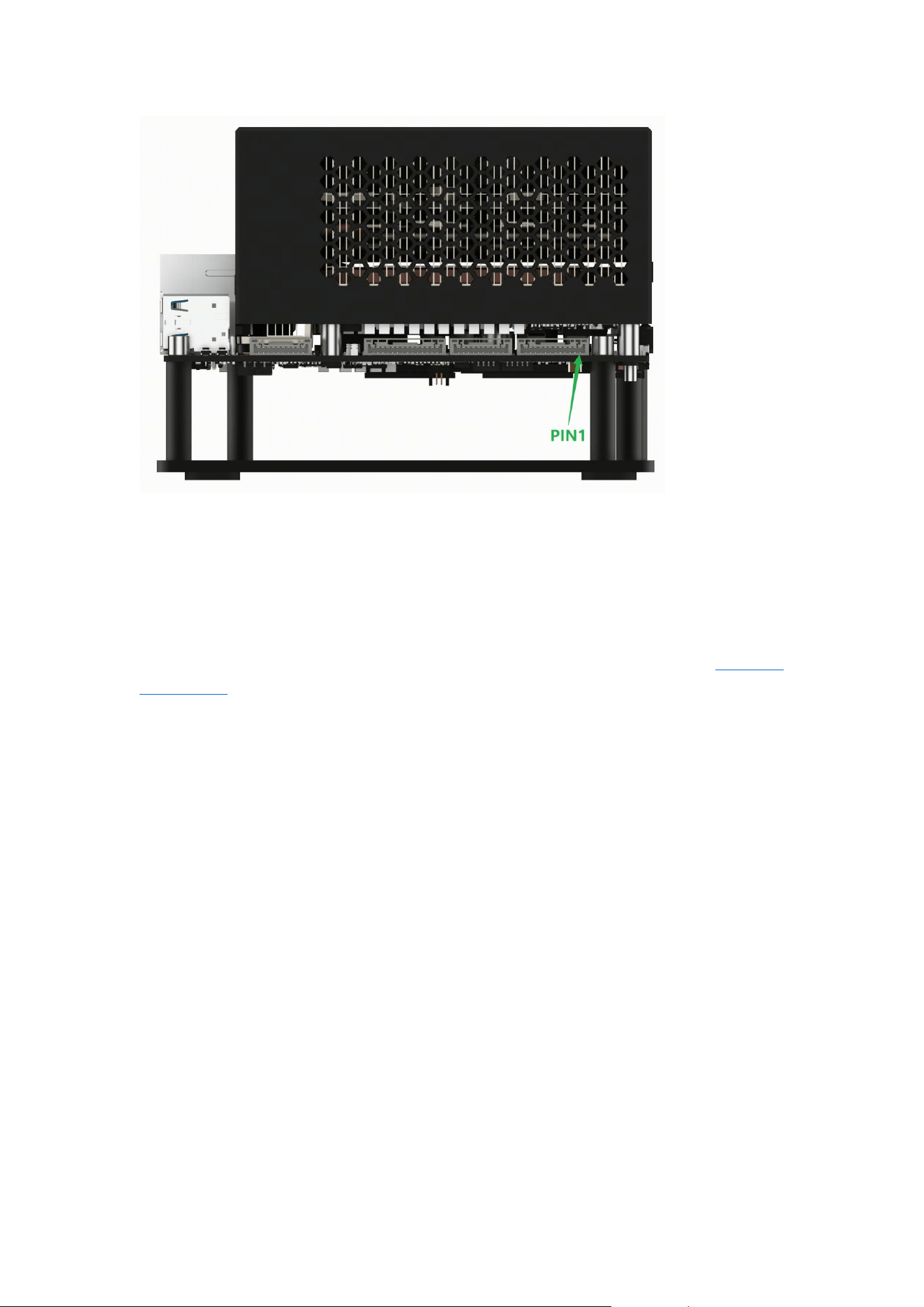
MCU-CAN Interface (J16)
The RDK S600 Developer Kit includes a CAN bus interface for the MCU domain. This
interface uses a 12-pin latching connector, providing 5 MCU domain CAN interfaces. The
120Ω termination resistor can be enabled or disabled using the SW6 switch. See
Interface
Description for MCU-CAN interface signal definitions.
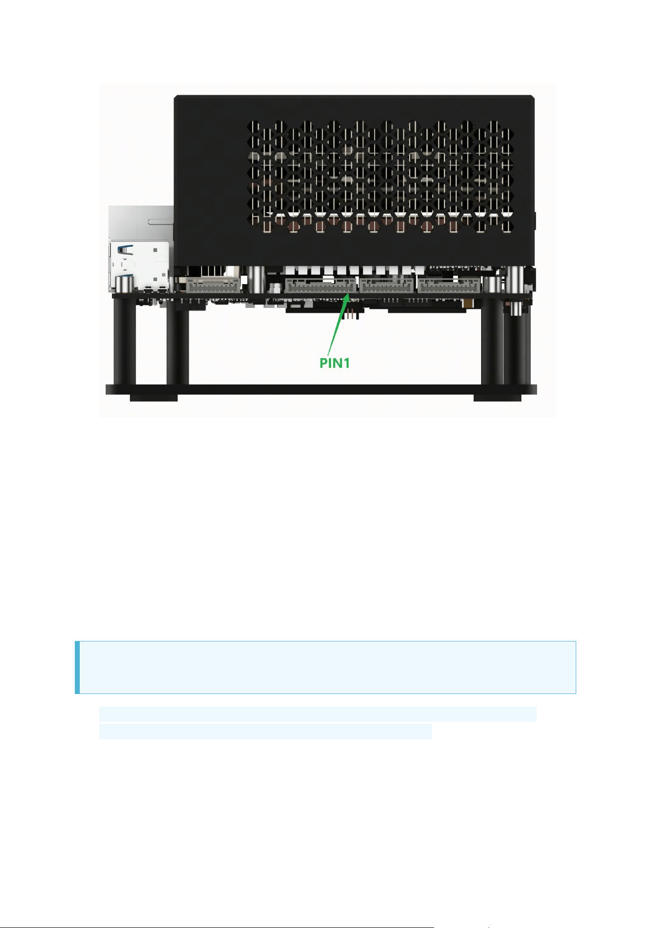
MAIN-CAN Interface (J17)
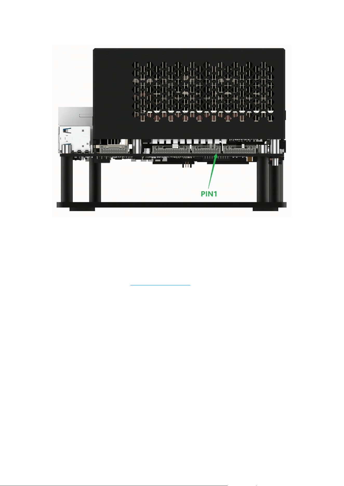
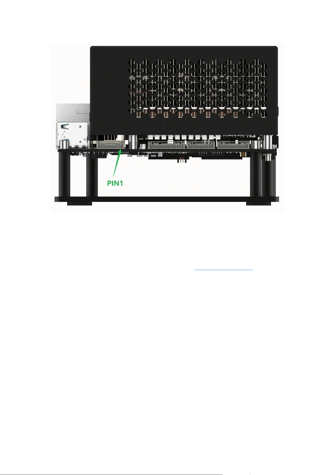
The RDK S600 Developer Kit includes a CAN bus interface for the MAIN domain. This
interface uses a 10-pin latching connector, providing 4 MAIN domain CAN interfaces. The
120Ω termination resistor can be enabled or disabled using the SW7 switch. See
Interface
Description for MAIN-CAN interface signal definitions.
RTC Battery Interface (J20)
The RDK S600 Developer Kit includes a battery interface for connecting an external RTC
battery.
Fan Interface (J21)
The FAN Connector is used to connect a cooling fan and supports fan speed control.
NOTE
The maximum supply current for 12V is 200mA. When the system is in light sleep and
deep sleep modes, the VDD_PERI_12V power supply is turned off.
Main Board Function Interface (J22)
The RDK S600 Developer Kit main board has an Automatic EXT CTRL Connector 12-Pin
connector, primarily for the following purposes:

• Extend the system operation LED and power indicator LED from the main board to the
outside for easy observation of the main board's operating status.
• Extend the flash switch, sleep button, reset button, and power switch to the outside of the
main board for convenient manual operation after final assembly.
NOTE
1. The green LED indicates whether the main board's small system has completed power-on.
The orange LED indicates whether the MAIN domain system of the main board is
operating normally.
2. The power supply of the Automatic EXT CTRL Connector 12-Pin interface is only allowed
to connect circuits described in the functional description. Connecting high-power loads is
prohibited.
3. When the system is in light sleep and deep sleep modes, the VDD_AON_PERI_5V and
DCIN_CONN power supplies remain on, while the VDD_PERI_3V3 power supply is turned
off. When connecting daughter boards, short-circuit protection circuits should be 预留 to
prevent power supply abnormalities on the main board caused by short circuits in the
external daughter board.
4. The maximum output currents for VDD_AON_PERI_5V, DCIN_CONN, and VDD_PERI_3V3
are 50mA, 5mA, and 100mA respectively.
2x 1GbE (U44)
Two Gigabit Ethernet interfaces, compatible with 1000BASE-T and 100BASE-T standards,
supporting auto-negotiation speed switching.
Pos
itio
n
Iden
tifie
r
Function Description
IP Configuration
Method
Default
IP
Address
Low
er
eth0
General-purpose Ethernet, user
needs to configure IP
External DHCP
assignment or manual
static config
None
Up
per
eth1
Management or dedicated
communication interface, built-in
static IP
Fixed static IP
192.168.1
27.10

2x 10GbE (U45)
This interface provides 2 10-Gigabit Ethernet ports.
1x 1GbE MCU (U80)
This interface is the MCU domain Gigabit Ethernet port.
Switch, Button, and LED Description
Indicator LEDs (D59/D60/D61)
Referenc
e
Name Off (State) On (State) Blinking (State)
D59
System
LED
System
abnormal
System
abnormal
System running
normally
D60
Power
LED
Power off Power on -
D61 Flash LED
Normal boot
mode
DFU flashing
mode
-
Switches (SW2/SW3)
Referenc
e
Name OFF ON Notes
SW2 Flash Switch
Normal boot
mode
DFU flashing
mode
-
SW3
Power
Switch
Power off Power on
△ p o sitio n is
ON
DIP Switches (SW6/SW7)
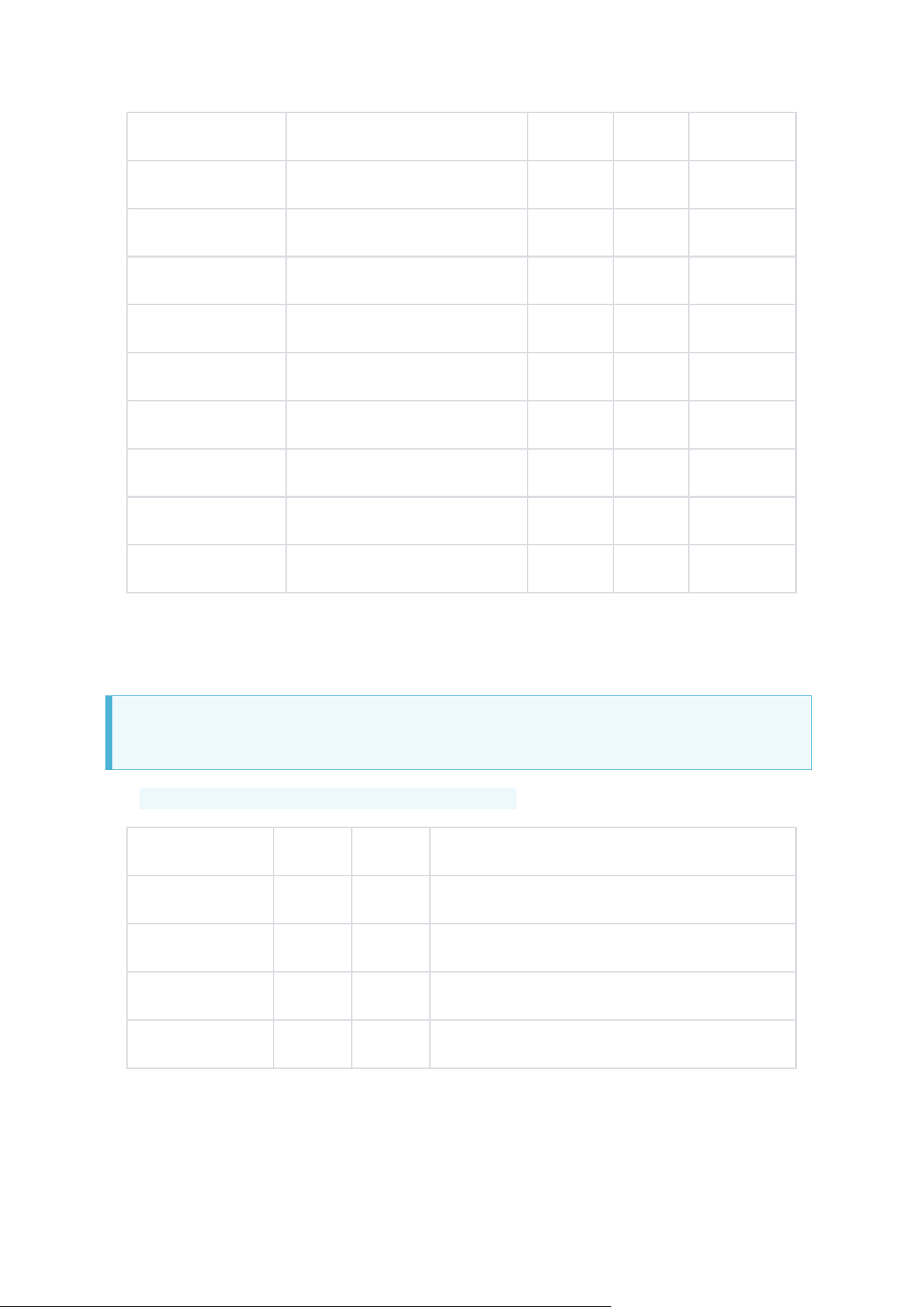
Reference
Name
OFF
ON
Notes
SW6
MCU-CAN1 120Ω
OFF
ON
-
MCU-CAN2 120Ω
OFF
ON
-
MCU-CAN3 120Ω
OFF
ON
-
MCU-CAN4 120Ω
OFF
ON
-
MCU-CAN5 120Ω
OFF
ON
-
SW7
MAIN-CAN1 120Ω
OFF
ON
-
MAIN-CAN2 120Ω
OFF
ON
-
MAIN-CAN3 120Ω
OFF
ON
-
MAIN-CAN4 120Ω
OFF
ON
-
BOOT (SW8)
NOTE
For SW8 DIP switch, set to 1 for ON, set to 0 for OFF.
Reference
D12
D13
Function
SW8
OFF
ON
System image boots from NVMe
ON
OFF
-
ON
ON
System image boots from UFS
OFF
OFF
System image boots from UFS
Buttons (K1/K2)

Refer
ence
Name Description Operation Method
K1
RST
Button
Resets the S600 system Pressing the button resets the system
K2
WAKE
Button
Controls S600 system
sleep or wake-up
Single-press button interrupt triggers
sleep and wake-up functions
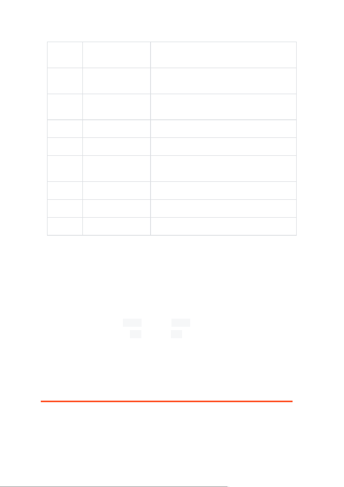
Connector Models
Connect
or
Connector Model Manufacturer
J1
430450400
Molex
J2
2034560003
Molex
J3 356-110A0CMBB1
Shenzhen Guangdezhong Electronics Technology
Co., Ltd.
J4
U262-161N-4BVC11
XKB Connectivity
J5
X1302WVS-67CE-LPV
01
XKB Connectivity
J6
X1302WVS-67CM-LP
V01
XKB Connectivity
J7/J8/J9
USB-303WSD-BRY
XUNPU
J10
A71-06H0-111N1
XKB Connectivity
J11/J13
AFC01-S22FCA-00
JS (Ju Shuo Electronics)
J12/J14
DY01-080S-B
KEL Corporation
J15
DY01-080S-B
KEL Corporation
J16
X1251WRS-12HF-LPS
W
XKB Connectivity
Connect
or
Connector Model Manufacturer
J17/J18
X1251WRS-10HF-LPS
W
XKB Connectivity
J19
X1251WRS-14HF-LPS
W
XKB Connectivity
J20
HDGC1002WV-S-2P
HDGC (Huade Gongchuang)
J21
470531000
Molex
J22
HX JN1.27-2X6 WZ
H4.9
Hanxia
U44
LPJG17561BGNL
LINK-PP
U45
LPJM17012BHNL
LINK-PP
U80
LPJG4806FBNL
LINK-PP
1.2Getting Started Configuration
Default Login Accounts
Before configuring the system, you need to log in first. The RDK S600 system provides two
default accounts:
Standard user: username sunrise, password sunrise
Superuser (root): username root, password root
Connecting to Wi-Fi
• Desktop
• Server
Refer to the Ubuntu 24.04 Wi-Fi connection tutorial.

Enabling SSH Service
The current system version has the SSH login service enabled by default. You can use the
following methods to turn the SSH service on or off.
• Desktop
• Server
For using SSH, please refer to Remote Login - SSH Login.
Setting Login Mode
Automatic Login on Character Terminal
Modify the serial-getty@ttyS0.service file to set up password-less login as follows:
1. Open serial-getty@ttyS0.service
# Log in as root user
vim /usr/lib/systemd/system/serial-getty@ttyS0.service
# Log in as sunrise user
sudo vim /usr/lib/systemd/system/serial-getty@ttyS0.service
1. Change the line containing ExecStart=-/sbin/agetty to:
ExecStart=-/sbin/agetty -a root --keep-baud 921600,115200,38400,9600 %I $TERM
Parameter explanation: The -a parameter specifies the username for automatic login. -o
'-p -- \\u' adds additional customization to the login process: preserves the current
environment variables and displays the username in the login prompt.
1. After restarting, the user will be logged in automatically.
Automatic Login on Graphical Terminal
To be updated.

Setting Up Chinese Environment
1. Install the command packages:
sudo apt install language-pack-zh-hans language-pack-zh-hans-base fonts-wqy-microhei
• language-pack-zh-hans: Contains Chinese language translation files, allowing the system
interface to display in Chinese.
• language-pack-zh-hans-base: Base language pack providing basic Chinese support.
• fonts-wqy-microhei: Installs Chinese fonts.
1. Open the terminal and enter the following command to open the language configuration
file:
sudo vim /etc/default/locale
Add or modify the following content in the file:
LANG=zh_CN.UTF-8
LANGUAGE=zh_CN:zh
LC_ALL=zh_CN.UTF-8
1. Execute the following command to update the configuration:
fc-cache -fv
source /etc/default/locale
Setting Up Chinese Input Method
After setting up the Chinese environment, the system's built-in input method is supported
by default. Press the Super (Windows key) + Space key combination to switch between
different input methods.
Setting Up RDK Studio
RDK Studio is an AI-native desktop workspace designed for robotics development. It
integrates Moss conversation, project workspace, device connection, remote development,
flashing, local models, and on-board agents into a single native window.
For the usage instructions of RDK Studio, please refer to the RDK Studio User Manual
.
NoMachine Configuration
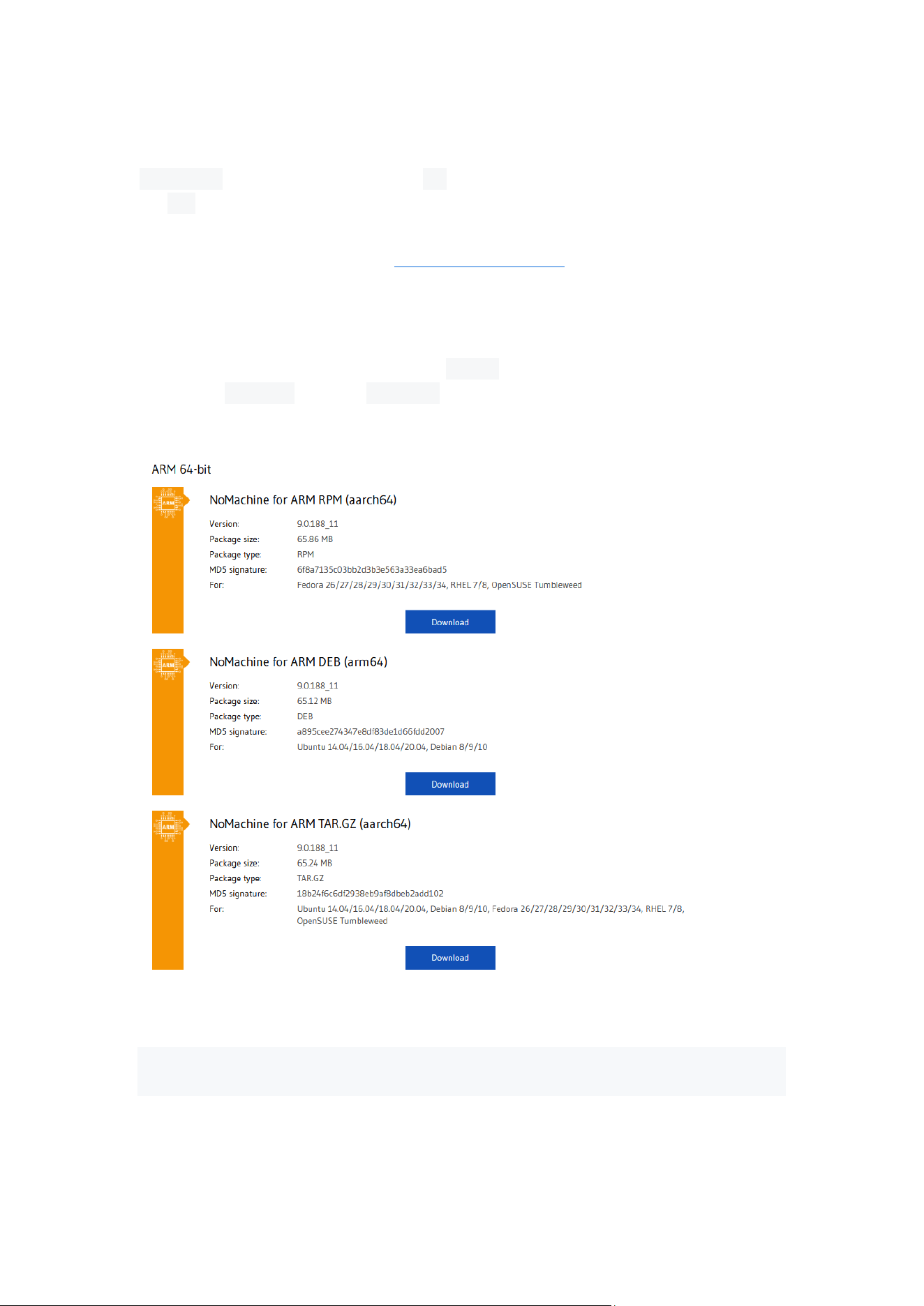
NoMachine currently does not support apt download. You need to obtain
the deb package from the official website.
Official NoMachine download URL: NoMachine Download
Download the installation package
After entering the official website, find the ARM64 version of the installation package
suitable for RDK S600 and click Download.
Installation
sudo apt update; sudo apt upgrade -y // Ensure the current software is up to date
dpkg -i nomachine_*_arm64.deb
Configuration and Startup

Configure the server to allow remote connections:
sudo systemctl start nxserver
Set NoMachine to start on boot:
sudo systemctl enable nxserver
Set EGL Capture to yes. This is a screen capture feature provided by NoMachine, mainly
used to improve the remote desktop experience in specific display server environments:
sudo /etc/NX/nxserver --eglcapture yes
This command takes effect after a reboot. You can double-check with the following
command; EGL Capture has been enabled indicates that the feature has been written to
the configuration file.
if [ -f "/usr/lib/systemd/user/org.gnome.Shell@wayland.service" ] && grep -q
"nxpreload.sh" "/usr/lib/systemd/user/org.gnome.Shell@wayland.service" && [ -f
"/usr/share/applications/org.gnome.Shell.desktop" ] && grep -q "nxpreload.sh"
"/usr/share/applications/org.gnome.Shell.desktop" && [ -f "/usr/NX/etc/node.cfg" ] &&
grep -q "EnableEGLCapture 1" "/usr/NX/etc/node.cfg"; then echo "EGL Capture has been
enabled"; else echo "Not enabled"; fi
Restart the NoMachine service:
sudo systemctl restart nxserver
Restart the S600
Due to NXServer configuration issues, connecting directly after performing the above
operations will result in a black screen. A reboot is required before use.
For using NoMachine, please refer to Remote Login - NoMachine Login.

User Management
Changing the username
Using the new username usertest as an example:
# Terminate all processes of the sunrise user
sudo pkill -u sunrise
# Rename the sunrise user to usertest
sudo usermod -l usertest sunrise
# Change the user's home directory to /home/usertest
sudo usermod -d /home/usertest -m usertest
# Change the user password
sudo passwd usertest
Finally, update the automatically logged-in username for the desktop service:
• gdm: RDK S100 default desktop service. Change AutomaticLogin = sunrise in
the /etc/gdm3/custom.conf file to AutomaticLogin = usertest.
• lighttdm: Change autologin-user=sunrise in
the /etc/lightdm/lightdm.conf.d/22-hobot-autologin.conf file to autologin-user=usertest.
Adding a new user
Using the new user usertest as an example:
sudo useradd -U -m -d /home/usertest -k /etc/skel/ -s /bin/bash -G
disk,kmem,dialout,sudo,audio,video,render,i2c,lightdm,vpu,gdm,weston-launch,graphics,j
pu,ipu,vps,misc,gpio usertest
sudo passwd usertest
sudo cp -aRf /etc/skel/. /home/usertest
sudo chown -R usertest:usertest /home/usertest
You can also refer to the username change method to set the newly added user as the
automatically logged-in user.