1
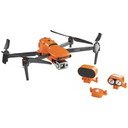
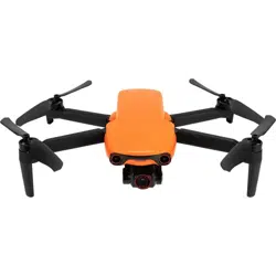
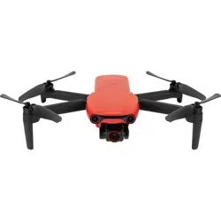
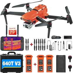
EVO II Enterprise
User Manual

2
Legend keys
Please pay attention to the legend keys in this Manual.
Warning: remind the possible danger
Important: Matters needing attention in flight operation.
Remark: supplementary information
Reminding: reminding information to get the best operating experience of the EVO Ⅱ
Enterprise series.
References: Page numbers to help you find chapters that contain relevant information in
this Manual.
Trademark Information
Trademarks EVO Ⅱ Dual 640T Enterprise™, EVO Ⅱ Pro Enterprise™, Autel Explorer™,
Starpoint™ and Autel Robotics® are registered trademarks of the Shenzhen Autel Robotics Co.,
Ltd (hereinafter referred to as “Autel Robotics”) in China and other countries/regions. All other
products and company name mentioned in this Manual are the registered trademark of their
respective owners.
Copyright
Without the explicit consent of Autel Robotics, do not copy or forward any part of the Manual in
or by any form (electronic, mechanical, reproducing, recording or other forms).
Patent Information
This product was obtained according to patent procedures. The patent numbers are as follows:
US7979174
IL192490
US9260184
CA2815885
US9979000
US10224526
US10044013
US10115944
US10090496
US10074836
US10341573

3
US10399699
US10414514
Disclaimer
In order to ensure successful operation of your EVO Ⅱ Enterprise aircraft, please abide by the
operating instructions and procedures of this Manual.
Children must use this aircraft under the supervision of an adult. The aircraft shall be kept out of
the reach of children when it is not used.
If user fails to abide by the safe operating instructions, Autel Robotics will assume no
responsibility for any product damage or loss--direct or indirect, legal, special or economic loss
(including but not limited to profit loss) during use, and will not provide warranty service. Never
modify your product by using any incompatible component or any method that is not required in
Autel Robotics official description.
This Manual will show you the safe operating procedures of aircrafts. Please acknowledge that
your operation will not endanger your and other personal and property safety. In order to ensure
your use of the latest version, please visit: www.autelrobotics.cn/download/8.
Data Storage and Use
The backup service function of this product is disabled by default, so user and flight information
will not be uploaded or propagated through mobile device. When Autel Explorer is connected with
an aircraft, the flight log including the flight remote sensing data will be uploaded and saved in the
Autel Robotics data server. All remote sensing data and flight logs are stored in the data server in
the United States, but the data can be uploaded automatically only when the flight log backup
option is enabled. Without the explicit authorization of user through Autel Explorer, Autel
Robotics customer service team has no right to access to the flight log data. With the authorization,
it is only allowed to access to the flight logs within the selected time.
Various still images, motion images and data from the aircraft sensor will be stored in the internal
drive of aircraft. If your UAV needs repair, then the information stored in the internal memory unit
can be used for problem diagnosis. This information will not be retained, unless for processing
service or repair. Never delete or change any data stored in the internal memory unit in any form,
otherwise Autel Robotics will not provide warranty. The data collected by Autel Robotics are for
providing support and service and improving product performance. We will treat your privacy
seriously. We can agree to disclose any uploaded data only when the law requires. For privacy
right policy, please visit www.autelrobotics.cn/page/privacy.
Safe operation guide
Battery safety
The EVO II Enterprise UAV is powered by lithium-ion polymer batteries. Danger may be caused
by improper use of lithium-polymer/lithium-ion batteries. Please ensure that all the following
battery use, charging and storage guidelines are strictly followed.

4
Warning
Only the battery and charger provided by Autel Robotics are allowed. Neither modify battery
and its charger nor use replace them with the third party equipment.
The electrolyte in the battery has strong corrosion. If the electrolyte accidentally touches your
eye or skin, immediately rinse with clear water and timely see a doctor.
Battery use
When the aircraft battery is installed or removed, be sure to turn off the aircraft power. Other
precautions are as follows:
Only the battery and charger sold or provided by Autel Robotics for the EVO Ⅱ Enterprise
series are allowed. The use of any unapproved battery or charger may cause fire, explosion,
leakage or other dangers. Autel Robotics will assume no responsibility for any consequence
of using the battery or charger of third party.
Never decompose, scratch, extrude, bend, pierce, cut, distort or damage the battery in other
forms. Otherwise the fire, explosion, leakage or other dangers may be caused.
Once the battery is found with bulge, smoke, leakage or any damage, it is necessary to stop
use or charging immediately and soak the battery into a vessel containing saline water.
Do not expose the battery to temperatures below -10℃ or above 40℃. Exposing the battery
to extreme temperatures will shorten its service life and may cause fire, explosion or other
permanent damage.
Exposing the battery below 5℃ may speed up battery discharge.
Do not use the battery in a strong electrostatic or electromagnetic environment.
Do not expose the battery in fire, explosion or other danger.
If the aircraft falls into water, the battery shall be taken out immediately after it is recovered.
Place the battery in an open space and keep a safe distance from flammable objects till that
the battery is fully dried. Stop the use of the battery, and contact the customer service center
for replacement.
Battery charging
At most 90 minutes are required to fully charge the aircraft battery, but the charging time is related
to the remaining battery level.
Other precautions are as follows:
Never use the damaged battery charger.
When the charger is not used, disconnect it from the aircraft battery and power supply.
The charging is allowed only after the battery is cooled to room temperature. If the battery is
connected with the charger immediately after flight, the overtemperature protection function
may be activated to stop battery charging till that the battery is fully cool.
Battery storage
The battery shall be protected from close contact with water source or heat source when storage.
The battery shall be stored in a dry and well-ventilated place in room temperature (ideal
temperature of 22°C-28°C.
Other precautions are as follows:
The battery shall be kept out of the reach of children and pets.
Never place the battery in direct sunlight or near sharp object, water, metal or reactive

5
chemical.
The storage of the battery in extreme temperature will shorten the battery service life.
If the battery is not used for 6 day above, it shall be stored in -10°C-30°C.
If the battery is not used for long, the battery service life will be shortened.
Battery disposal
The battery must be thoroughly discharged before it is discarded.
The battery shall be sent to designated recycling station for proper disposal.
Flight environment
Please abide by the local laws and regulations on UAV flight. Fly only in the designated
aircraft movement area, and use Autel Explorer App to set the satisfactory distance and
height limits.
Do not fly in dangerous situations or severe weather conditions such as tornadoes, rain, hail
and snow.
Do not fly this aircraft near facilities that can generate electromagnetic interference, such as
power plants, transmission lines, substations, wind power towers, and radio and television
towers.
Fly in an open and safe area. Stay away from obstacles that may interfere with GPS signals,
such as buildings and trees.
Be extremely careful when flying in an environment above sea level 7,000m, at which the
performance of the battery and power system of the aircraft may be affected.
Pre-flight
Before the UAV flies, it is always necessary to pay attention to the following matters:
The remote controller, flight battery and mobile device with Autel Explorer App should be
fully charged.
The propellers are correctly installed without damage.
Front and rear arms of the aircraft are completely extended.
The motor, gimbal and camera can work normally after the aircraft is powered on.
All warnings and errors displayed on App have been handled.
Only accessories provided with this aircraft or sold or authorized by Autel Robotics can be
used with this aircraft. Using unapproved accessories can bring serious safety risks and will
invalidate the product warranty.
In-flight
The aircraft shall keep away from people, vehicle and other moving object when taking off
and landing.
Do not let the aircraft out of your sight.
Do not fly near water.
Do not cancel the auto return process in the event of low battery alarm. Otherwise the aircraft
may return to the return point due to insufficient power.
When Autel Explorer App displays an alarm, immediately carry out operation according to
relevant specification.
Ensure that you are free of drunkenness, high blood pressure, dizziness, fatigue or any other
physical condition that may affect the safe operation of the aircraft.

6
Warning
If any part of the aircraft or the remote controller fails to work normally or is visibly
damaged, please do not fly any longer and contact the Autel Robotics customer service team:
www.autelrobotics.cn/page/service
Storage and maintenance
Carefully check each part of the aircraft after any collision or extrusion. Store the aircraft and its
accessories out of the reach of children and pets.
Store the aircraft and its accessories in a cool and dry place.
Keep the aircraft away from water source and heat source.
The recommended temperature of the aircraft shall be 22℃-28℃.

7
Catalog
Chapter 1
............................................................................................................................................
9
About the Manual
.............................................................................................................................
9
1.1 Instructions for the first flight
...................................................................................................
9
1.1.1 Documents
.........................................................................................................................
9
1.1.2 Autel Explorer App installation
......................................................................................
9
Chapter 2
..........................................................................................................................................
10
Be familiar with your smart UAV.
.................................................................................................
10
2.1 Aircraft
.......................................................................................................................................
10
2.2.1 Software instruction
.......................................................................................................
10
2.1.2 Flight indicator
...............................................................................................................
13
2.1.3 Aircraft battery
..............................................................................................................
14
2.1.4 Gimbal and camera
.......................................................................................................
16
2.1.5 Flight control system
......................................................................................................
22
2.1.6 Intelligent flight features
...............................................................................................
23
2.1.7 Omnidirectional binocular vision system
....................................................................
25
2.1.8 Extension accessories
.....................................................................................................
28
2.1.9 Industry application
......................................................................................................
30
2.2 Remote controller
......................................................................................................................
34
Chapter 3
..........................................................................................................................................
39
Flight preparation
...........................................................................................................................
39
3.1 Battery preparation
..................................................................................
错误!未定义书签。
3.2 Remote controller preparation
................................................................................................
41
3.2.1 Extend remote controller
..............................................................................................
41
3.2.2 Turn on/off remote controller
.......................................................................................
41
3.2.3 Aircraft and remote controller pairing
........................................................................
41
3.33.3 Aircraft preparation
............................................................................................................
42
Chapter 4
..........................................................................................................................................
45
Flight Operation
..............................................................................................................................
45
4.1 Check list before flight
..............................................................................................................
45
4.2 Flight operation
.........................................................................................................................
45
4.2.1 Motor start and aircraft takeoff (American manipulator)
................................................
45
4.2.2 Manipulator control (American manipulator)
...................................................................
46
Chapter 5
..........................................................................................................................................
49
Maintenance and service
................................................................................................................
49
5.2 Solutions to common faults
......................................................................................................
49
5.3 Storage and maintenance
.........................................................................................................
51
5.4 Warranty
....................................................................................................................................
51
5.5 Customer service
.......................................................................................................................
52
5.5.1 Customer support
..........................................................................................................
52
5.5.2 Maintenance service
......................................................................................................
53
Chapter 6
..........................................................................................................................................
54
Annex
................................................................................................................................................
54

8
6.1 Authentication information and restricted area
....................................................................
54
6.1.1 Authentication information
...........................................................................................
54
6.1.2Diagram of restricted area
.............................................................................................
55
6.2 Specifications
.............................................................................................................................
57

9
Chapter 1
About the Manual
Thank you for your purchase of EVO II Enterprise UAVs. With this Manual, you can understand
the features of EVO II Enterprise products and learn to operate this aircraft and remote controller
optimally. Before first use of EVO II Enterprise products, please read this Manual and attached
documents and get ready this Manual at any moment for reference.
1.1 Instructions for the first flight
1.1.1 Documents
The following documents provide a start guide for you to use the EVO Ⅱ Enterprise UAVfor the
first time.
1. Product List: a list of all items that shall be included in the packing box. For any missing,
please contact the Autel Robotics customer support or your local retailer.
2. User Manual: to instruct you to well learn operating methods of EVO Ⅱ Enterprise products.
3. Quick Start Guide: basic knowledge to operate VO Ⅱ Enterprise products.
4. Disclaimer and Safe Operation Guide: instructions to safely operate VO Ⅱ Enterprise
products.
5. Quick Start Guide for Batteries: basic knowledge of smart batteries.
Download website:www.autelrobotics.cn/download/8.
Warning
Please check the aircraft and other accessories listed on the Product List in packing box. Do
not modify this aircraft by using any incompatible component or any method that is not
required in official description.
1.1.2 Autel Explorer App installation
Autel Explorer App can provide the real-time image transport for your mobile device, and achieve
control on aircrafts and cameras.
Search Autel Explorer in App Store, Android App store or Google Play, and install and use.
10
Chapter 2
Be familiar with your smart UAV.
The EVO II Enterprise integrate a 16x zoom imaging system and customized extension
accessories to optimize the aerial operation mechanism to meet the flight needs of inspection,
search and rescue, law enforcement, and fire protection in various professional fields. The EVO II
Enterprise come standard with a 7.9-inch 2000nit high-brightness screen remote controller, which
can realize 1080P real-time picture return.
The EVO II Enterprise adopt the foldable body design. It is small and light, easy to carry to
operate, and can easily achieve a maximum speed of 72 km/h, a flight time of 42 minutes, and an
operating distance of 13km (FCC) in terms of performance. The EVO II Enterprise comprise two
models of EVO II Pro Enterprise and EVO II Dual 640T Enterprise. The EVO Ⅱ Dual 640T
Enterprise are equipped with a 640×512 thermal imaging camera and an 8K visible light camera,
which can take thermal imaging and visible light images at the same time, and support fused
display of the two, to provide more detailed images. The EVO II Enterprise are equipped with a
1-inch CMOS blessed 6K resolution ultra-high-definition lens, being easy to achieve
professional-level imaging experience.
The EVO II Enterprise are equipped with 12 vision sensors on the body, with advanced functions
such as intelligent flight and omnidirectional obstacle avoidance. The App provides users with
dozens of intelligent photography modes, as well as flight modes of multiple tasks such as
rectangular tasks, polygon tasks, waypoint tasks and oblique photography. Users can choose
corresponding modes for route planning according to actual needs.
2.1 Aircraft
2.2.1 Software instruction
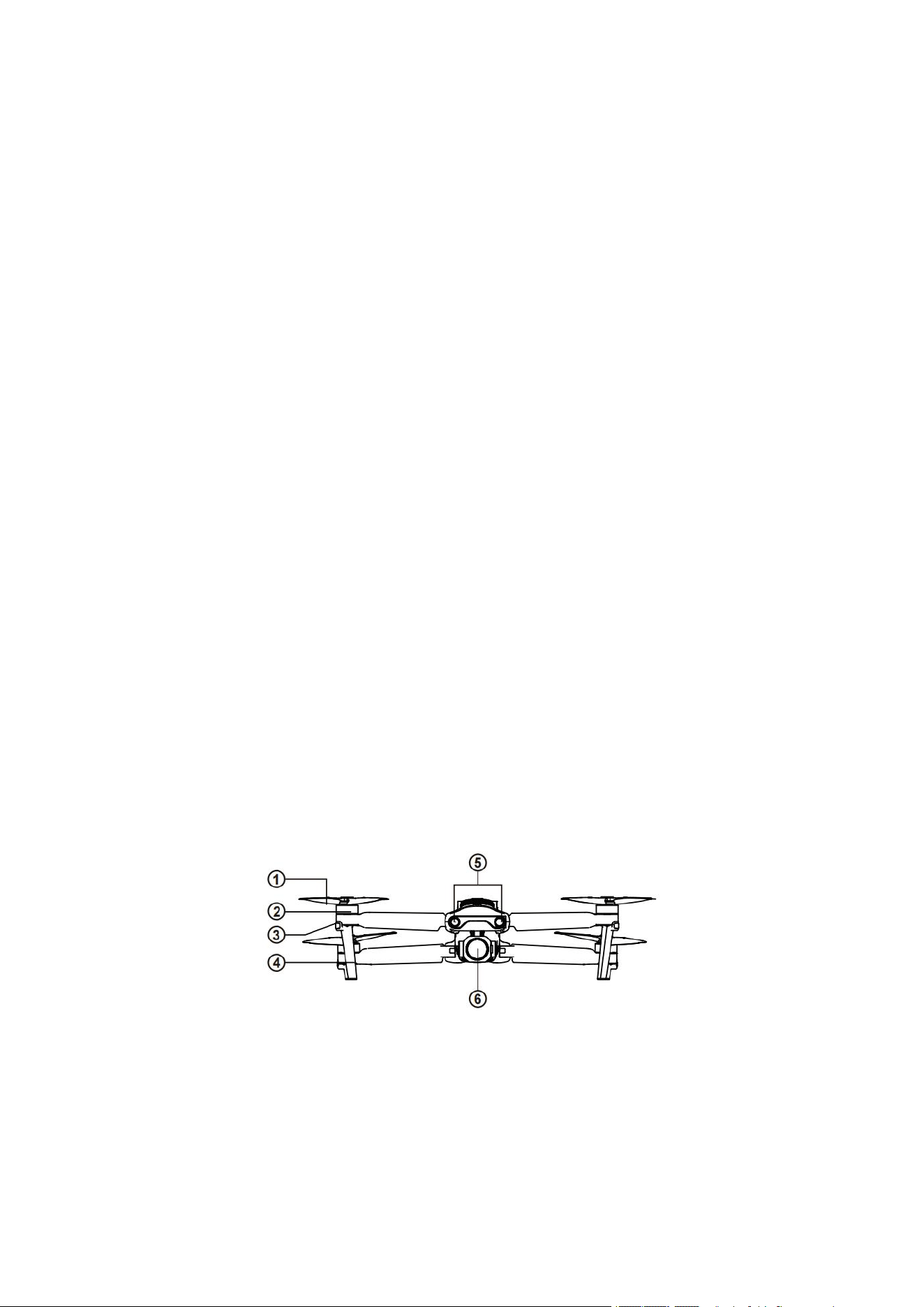
① Propeller
④ Undercarriage
② Motor
⑤ Forward vision system
③ Front LED indicator
⑥ Gimbal camera
11
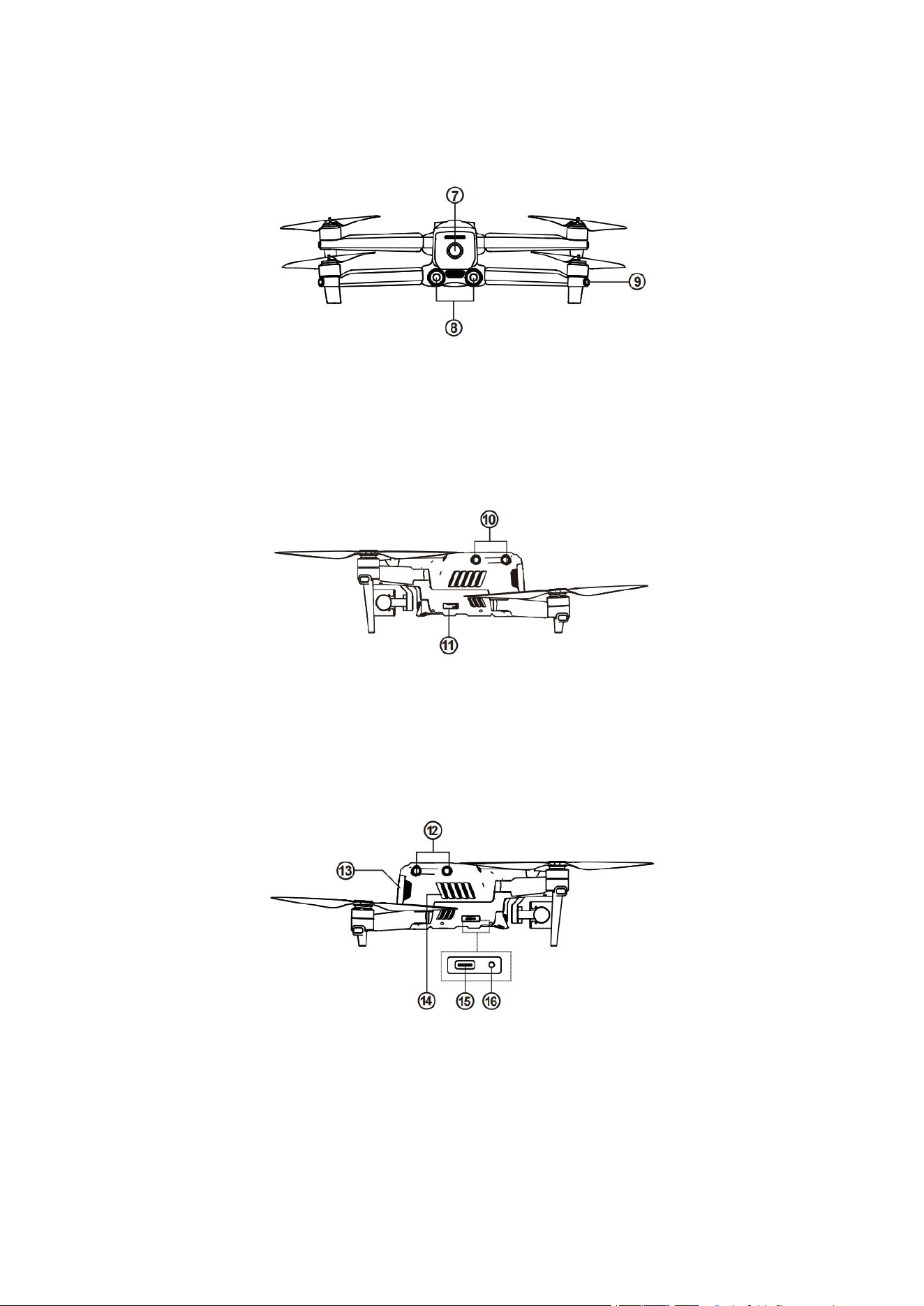
⑦ Power button
⑨ Rear LED indicator
⑧ Backward vision system
⑩ Left vision system
⑪ SD card slot
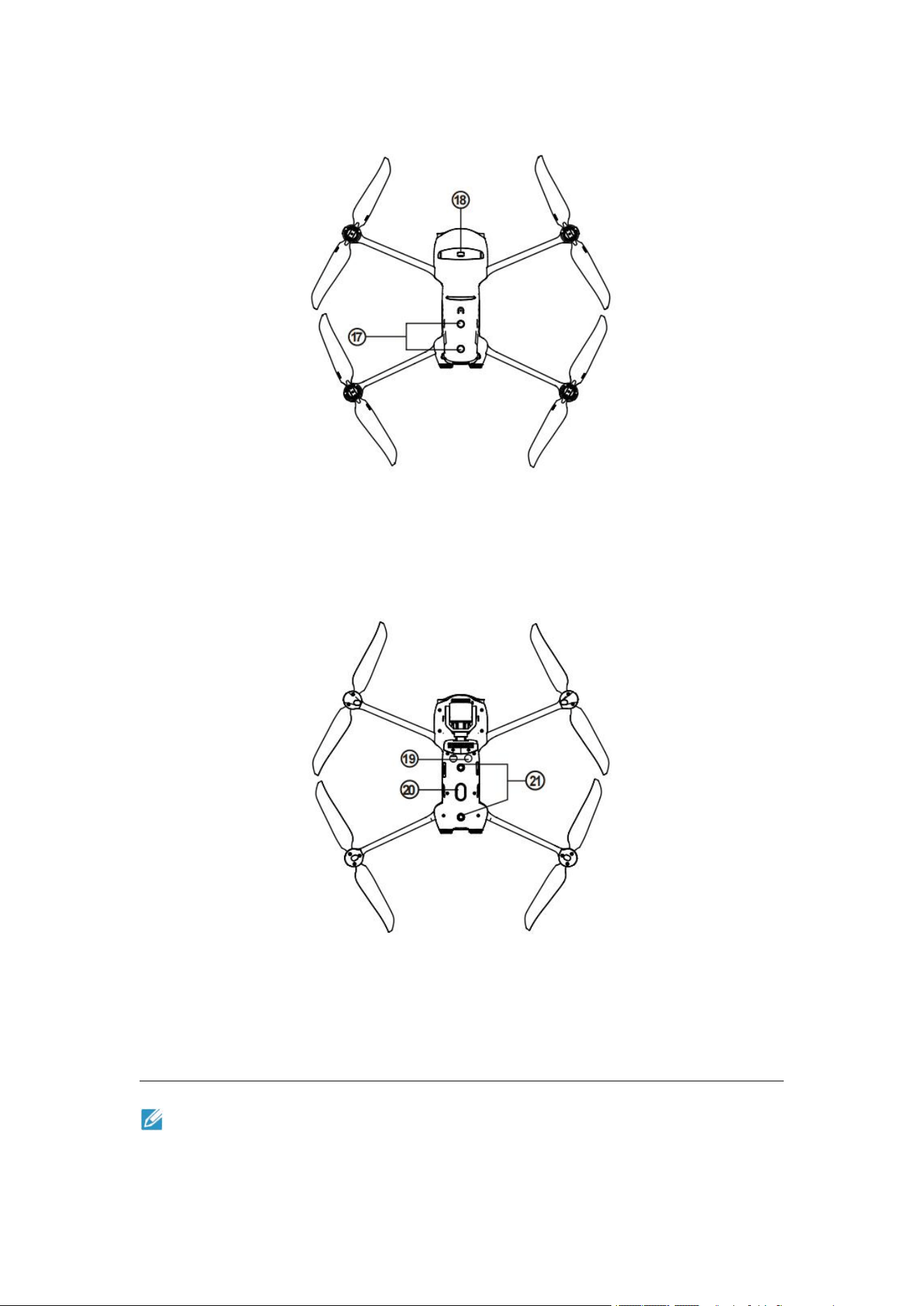
⑫ Right vision system
⑮ USB-C port
⑬ Aircraft battery
⑯ Remote controller pairing button/pairing
indicator
⑭ Fan outlet
12
⑰ Upper visual system
⑱ Extension accessory interface
⑲ Ultrasonic sensor
㉑ Lower visual system
⑳ LED fill-in light
Remark
The right side is equipped with a protective cover, for protecting the USB-C port and Remote
controller pairing button/pairing indicator. Ensure that the protective cover is kept in the

13
closed state during flight.
2.1.2 Flight indicator
The aircraft has one LED indicator at the end of each arm. The front LED shows steady red to
help you to find the head direction. The rear LED shows the current flight status of aircraft. The
following table shows the meaning of each status indicator.
Designated symbol of indicator:
Designated symbol of color:
Slow flash: flash once every two seconds
R
Red
Quick flash: flash twice per second
G
Green
Alternate flash: alternate flash in different colors
Y
Yellow
Status definition of flight LED indicator
Normal status
RGY - alternate flash
System self-test
YG - alternate flash
Preheat
G - slow flash
Aircraft in GPS mode
Warning
Y - slow flash
Aircraft in ATTI mode
Y - rapid flash
No connection between aircraft and remote controller
R - slow flash
Low battery warning
R - quick flash
Serious low battery warning
R - Normally on
Serious problem or IMU abnormality
RY - alternate flash
Compass is abnormal, and needs to be
calibrated/magnetometer interference
Compass calibration
Y - rapid flash
Prepare for compass calibration/aircraft under calibration
14
G - Normally on
Calibration successful
R - Normally red
Calibration failed
Gesture instructions
R - Quick flash
Receive gesture instructions
2.1.3 Aircraft battery
The rechargeable lithium polymer battery used in the EVO II RTK series has the characteristics of
high energy density and large capacity. It shall be charged with the provided special charger.
Basic functions
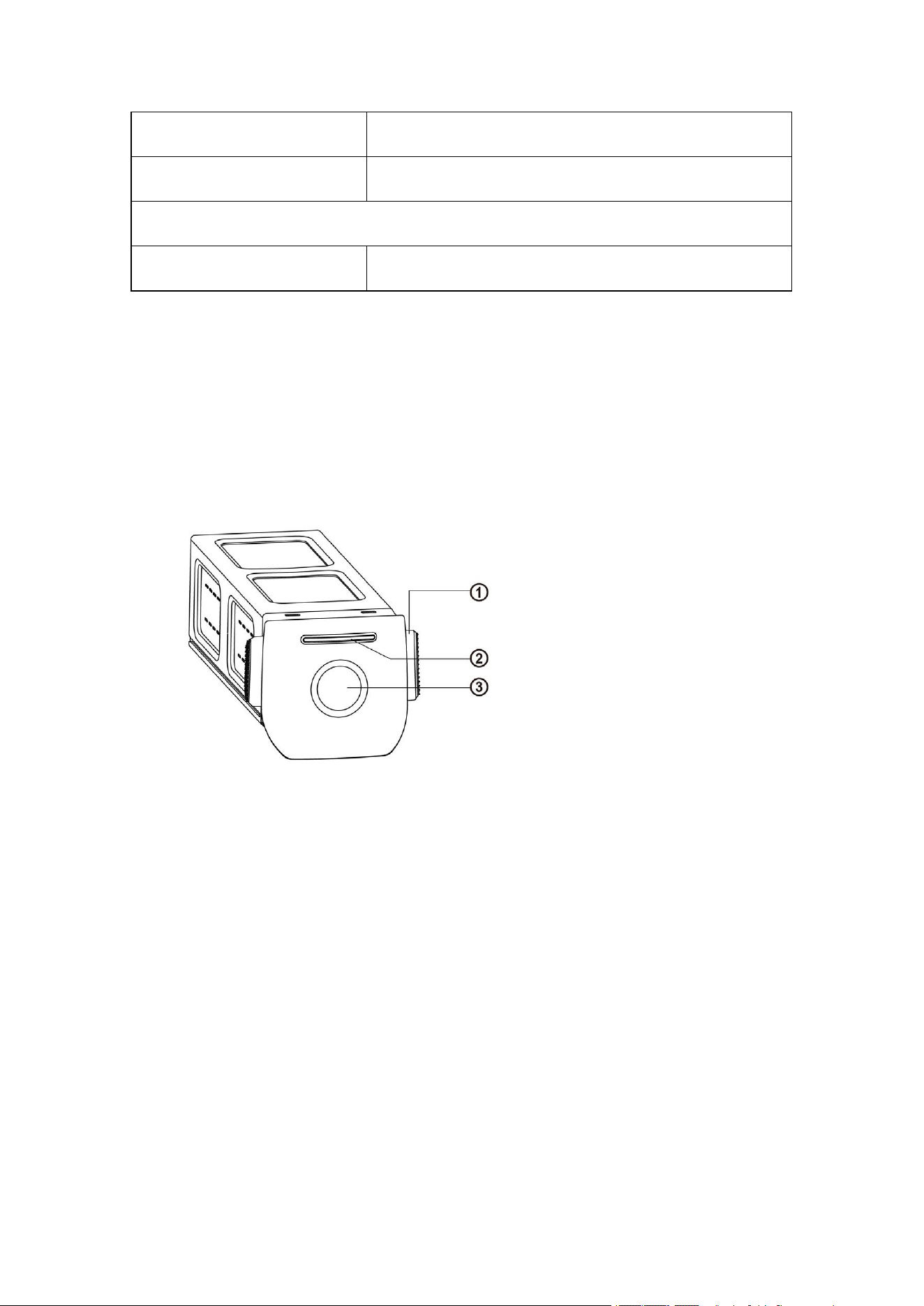
① Disconnect button
② Battery level indicator
③ Power button
Turn on battery
The battery shall be turned off before it is installed. After installation, long press the power
button for 3s. The battery level indicator will indicate the current battery level.
Turn off battery
Long press the power button for 3s to turn off battery. If the battery has been installed on aircraft,
The first and last LED lights will flash for five times to remind the shutting down. After all
battery level indicators are turned off, take the battery out of the aircraft.
Check battery level
When the battery is turned off, press the power button for 1 second and then release it quickly to
check the battery level. LED will indicate the current battery level, as shown below.
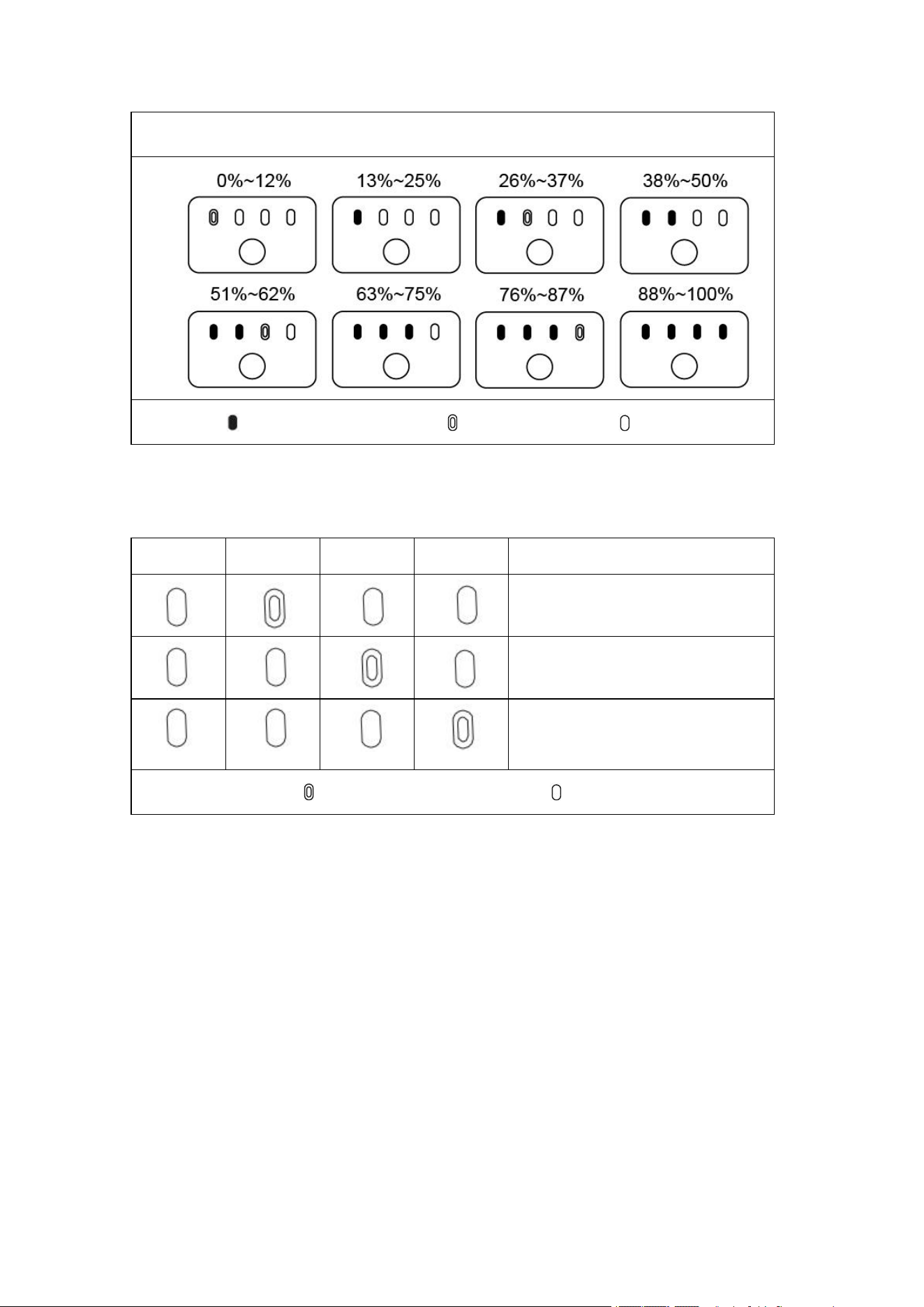
15
Battery level indicator status (non-charging status)
- Green is normally on - Green is flashing - Off
LED warning description
LED 1
LED 2
LED 3
LED 4
Warning description
The charging temperature is too high
or too low.
The charging current is high enough
to cause short circuit.
There is overcurrent, overload or
short circuit problem in the case of
discharging.
- Indicator is flashing - Off
Additional functions
The following functions can protect and prolong the battery service life.
Self-discharge protection for storage
If the battery is stored in high temperature environment or it is not used for 6 days and the battery
level is high, the self-discharge protection will be activated. The battery will automatically
discharge to a safe level, this is a default setting, and this discharging process takes 2-3 days.
Although the battery has no indication in the self-discharge period, it is normal that the battery
may be slightly hot. The discharge threshold can be self-defined with Autel Explorer App.
Low battery protection
in the case of low battery level, the battery will automatically enter sleep mode to avoid damage.
Under this mode, there will be no reaction when pressing the power button. To wake up the battery,
it is allowed to connect it with charger.

16
Charging temperature detection
the battery will stop charging in the case of charging temperature lower than 5℃ or higher than
45℃.
Overcurrent protection
The battery will stop charging if the charging current exceeds 8A.
Overcharge protection
The battery will automatically stop charging after it is fully charged.
Balanced protection
Each battery unit shall maintain voltage balance to avoid overcharge or overdischarge.
Overdischarge protection
The battery will automatically disconnect the power output function when it is not used and
completes the self-discharge period. This function is disabled in flight.
Short-circuit protection
The power supply will be disconnected once the short circuit is detected.
Power-down mode
The battery will turn off if there is no operation within 30 minutes.
Communication
During use, the aircraft will be continuously synchronous with battery to provide the real-time
information, including voltage, capacity, current, and temperature.
Low power consumption mode
To save power, this mode will be activated when the battery is idle for 6 days and the voltage is
lower than 11.6 V. After connected with the charger, the battery will resume normal functions.
2.1.4 Gimbal and camera
This aircraft is equipped with a high-precision 3-axis gimbal, which can keep the camera stable
while the aircraft is flying, thereby ensuring image stability and clarity. For normal working, the
gimbal must be at a temperature of -10℃ to 50℃. You can use the gimbal pitching thumbwheel of
remote controller or Autel Explorer App to adjust the gimbal pitch angle within the range of -30
degrees to 90 degrees.
EVO II RTK series provide replaceable gimbal modules for users:
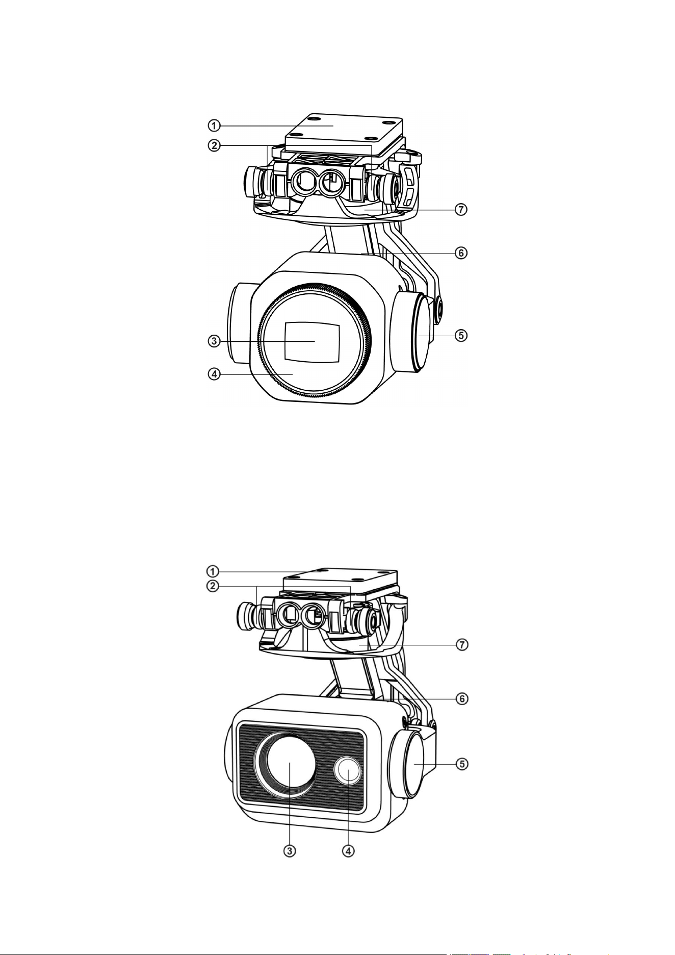
17
Gimbal of EVO II Pro Enterprise
① MCU installation disc
⑤ Pitching axis motor
② Shock absorber
⑥ Rolling axis motor
③ Camera
⑦ Yawing axis motor
④ Filter
Gimbal of EVO II Dual 640T Enterprise
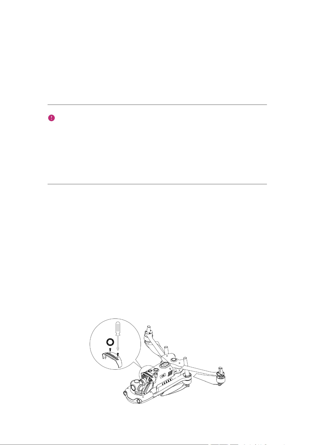
18
① MCU installation disc
⑤ Pitching axis motor
② Shock absorber
⑥ Rolling axis motor
③ Infrared ray camera
⑦ Yawing axis motor
④ 8K Camera
Important
The EVO II Enterprise camera gimbal is fixed by one gimbal protective cover that can
protect the gimbal from accidental rotation or damage during storage.
Please be sure to take down the gimbal protective cover before startup. Otherwise the gimbal
camera and circuit may be damaged.
When turning on the aircraft power switch, the gimbal will rotate automatically to carry out
self-test and calibration. Please ensure that there is no object that may hinder the gimbal
motion around the gimbal.
The gimbal includes two working modes:
Stabilization mode : The rolling axis remains horizontal while the pitching axis remains the
user-defined angle. This mode is used to capture stable image and video.
FPV mode: The rolling axis remains consistent with the rolling direction of the aircraft
while the pitching axis remains the user-defined angle. This mode is used for first-person
perspective.
Disassembly gimbal
1. The aircraft is placed on a horizontal surface, with the gimbal compartment facing upwards.
2. Unscrew the two screws that fix the gimbal protective cover with a T6 screwdriver, and then
remove the gimbal protective cover. Unscrew the screws that fix the FPC connector with a cross
screwdriver, and then pull out the connector cable interface from the slot.
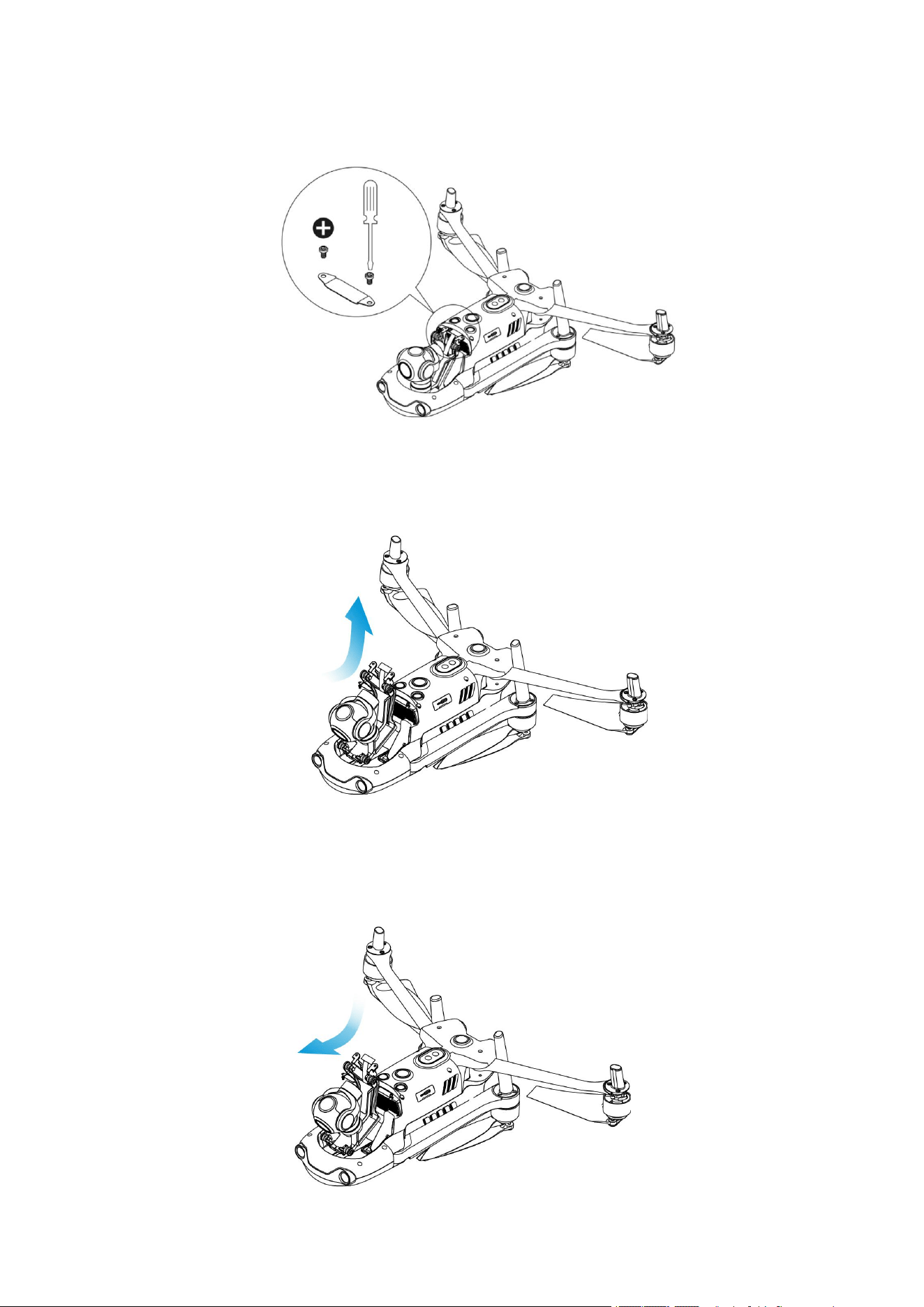
19
3. Gently pinch the tail of the shock absorber with your thumb and index finger. Slide the gimbal
back and up in a straight line along the gimbal compartment slot.
Gimbal installation
1. Pinch the tail of the shock absorber with your thumb and index finger. Slide the gimbal down
and forward in a straight line along the gimbal compartment slot.
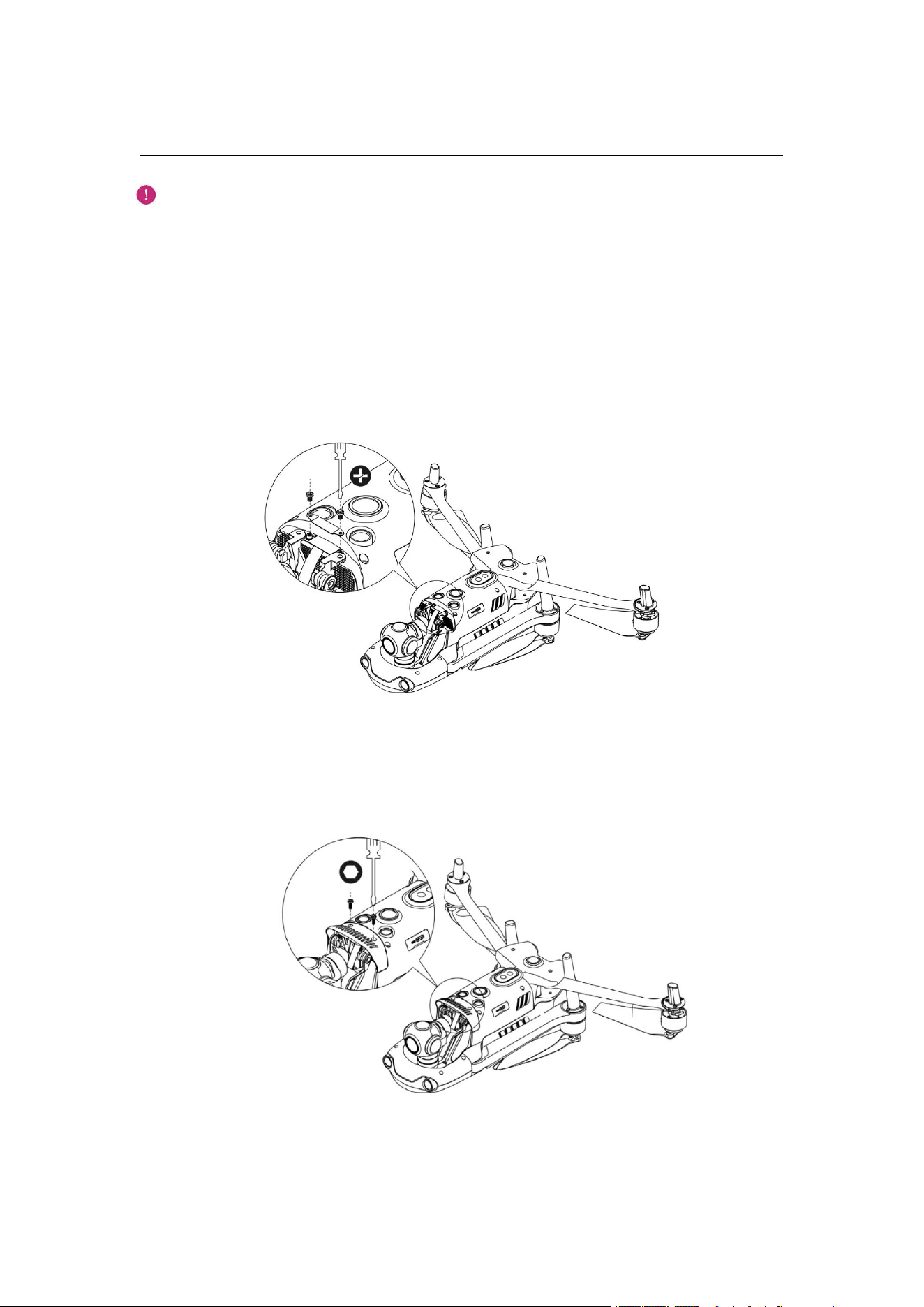
20
Important:
Please make sure that the ring at the front end of the gimbal is aligned with the two pins in
the gimbal compartment of the machine head.
Please make sure that the gimbal is in flush with the slot of the gimbal compartment.
2. Insert the connector cable port into its slot, and gently push it to the end when inserting. Place
the gimbal cover on the top of the gimbal compartment, and tighten the cover with a cross
screwdriver.
3. Insert a screw into a hole of the gimbal decorating part, and then screw it with a T6 screwdriver
until the screw is fixed but not being tightened. Repeat this step for other screws. Fully tighten the
two screws with the screwdriver.
4. Turn on the power switch of the aircraft. If the connector cable of the gimbal is connected
correctly, the gimbal will rotate automatically to carry out self inspection.
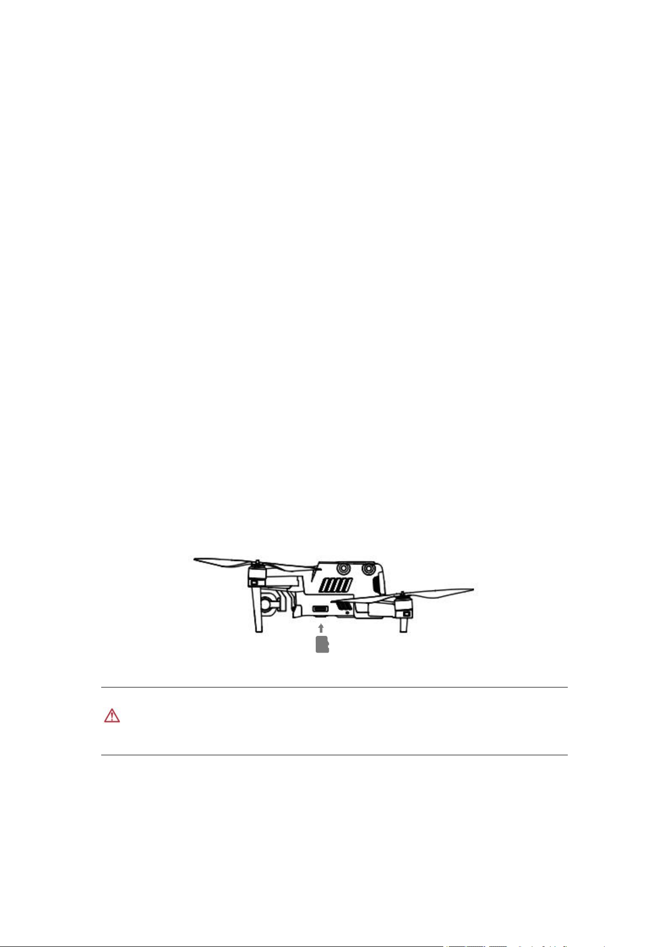
21
Camera
The EVO II Enterprise can be equipped with two cameras to use:
EVO II Dual 640T Enterprise: including 8K visible camera and an infrared camera. The
camera can work with visible light and infrared rays and in a dual-image mode. The 8K
camera can record 7680×4320 resolution video, which is 4 times 4K super-definition images,
and directly takes images of 48m pixels. The resolution of the infrared camera is up to 640x
512.
EVO II Pro Enterprise: the camera contains one 1 inch sensor, it can take images with a
resolution up to 20m (5472 x 3648) and record 5.5K videos of 30 frames, or 2.7K videos of
120 frames, and its code rate is up to 120 Mbps. The camera aperture is adjustable within
f/2.8 to f/11.
These two camera modules can support multiple shooting modes, including: Single shot,
Continuous shot, AEB, Time lapse, Pure night scene (in 4K JPEG format), Long exposure and
HDR imaging (in 4K JPEG format). The camera can save photos in DNG or JPG format and
record videos in MOV or MP4 format. The image and video can be saved in memory carried by
the aircraft or SD card.
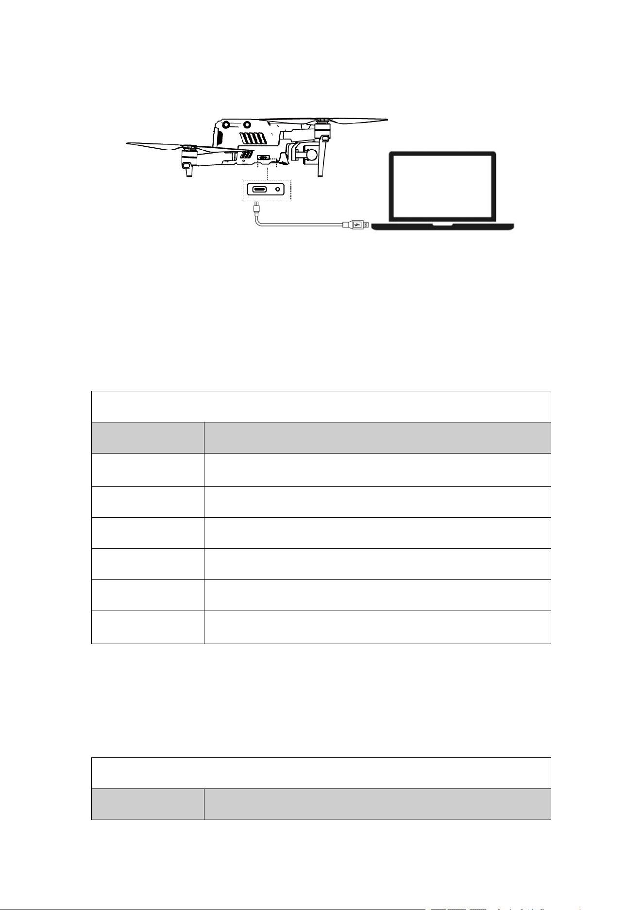
Use Micro SD card
Before the aircraft is turned on, first insert one Micro SD card in a port, as shown below.
EVO II Enterprise can support the SD card with the maximum storage capacity of 256GB. If you
want to shoot a high-definition video, you are recommended to use the Class 10 or UHS-3 Micro
SD card.
Warning
To prevent file loss, turn on the aircraft before the Micro SD card is taken out.
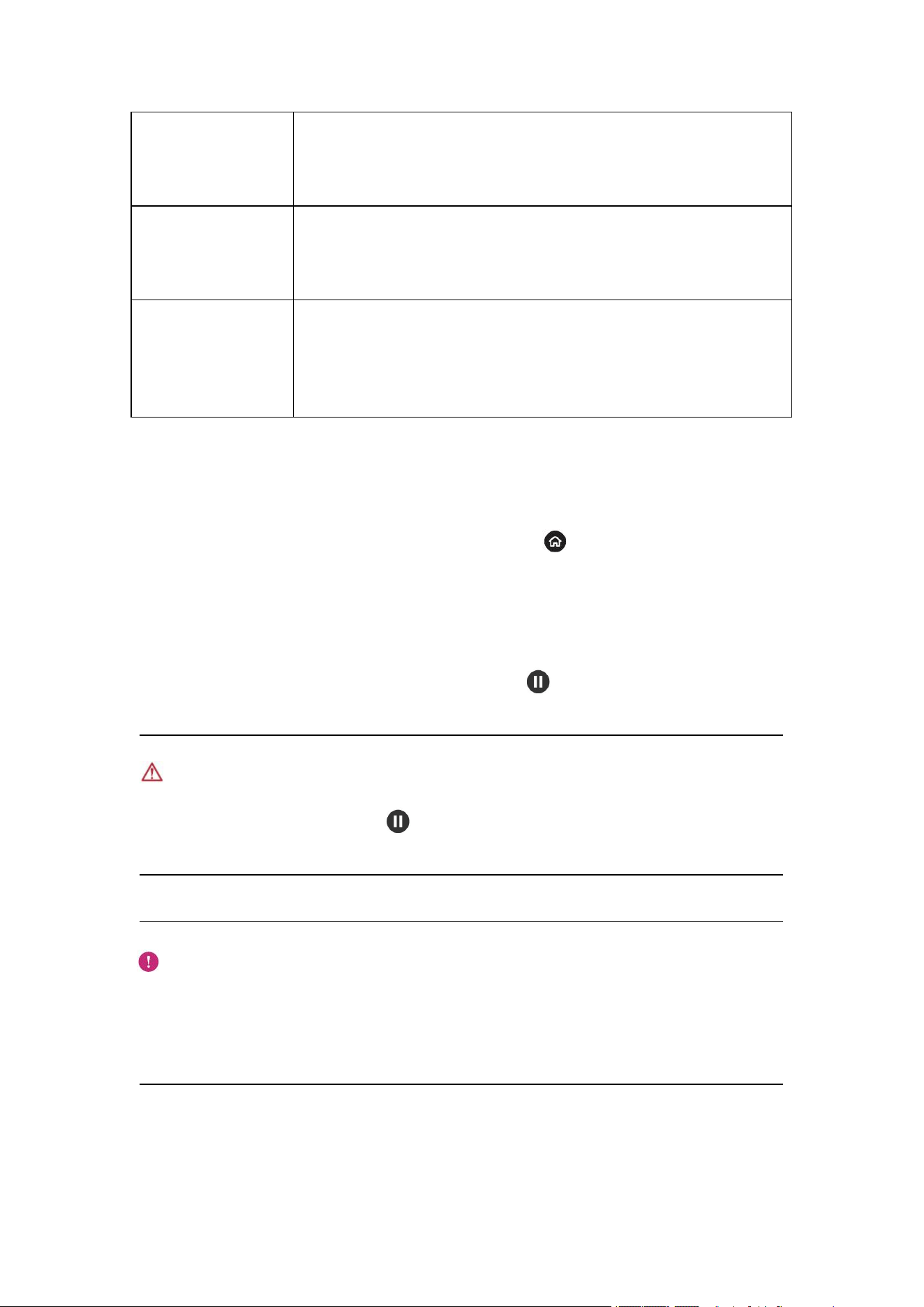
Transfer files to computer
To transfer images and videos to the computer, please connect the computer to the aircraft via the
USB-C port, as shown below.
22
2.1.5 Flight control system
EVO II Enterprise is to conduct stable and convenient flight control by its built-in intelligent flight
control system. This system can support multiple advanced functions, including course reversal,
fail-safe, Starpoint
TM
positioning system, etc. The working description of each module is as shown
in the table below.
Intelligent flight control system module
Module
Description
IMU
Use one 3-axis gyroscope and 3-axis accelerometer to measure
acceleration and angular speed.
Compass
Measure geomagnetic field and provide course reference of aircraft.
GNSS receiver
Receive the signal to determine longitude, latitude and altitude.
Barometer
Measure atmospheric pressure to determine the altitude of aircraft.
Ultrasonic sensor
Measure the distance between aircraft and ground.
Binocular vision
system
Support the forward, backward, left, right, upward and downward
binocular vision.
Flight Mode
According to GPS availability and flight conditions, EVO Ⅱ Enterprise series can automatically
switch between three flight modes.
Flight Mode
Flight Mode
Description
23
GPS mode
When the aircraft detects an appropriate GNSS signal, it will activate the
GPS mode. With the assistance of the forward and downward vision
systems, GPS can locate and avoid obstacles, provide stable and smooth
flight control, and support safety functions such as return, fail-safe, etc.
ATTI mode
When the GPS signal is weak and the light conditions cannot meet the
vision system, the ATTI mode is activated. The obstacle avoidance
function is disabled, and the altitude of the aircraft is controlled only
through its barometer.
Starpoint mode
In this mode, the aircraft works in the visual positioning mode, but the
environment and height are highly required. The environment must meet
the lighting conditions, that is, it must be bright and the ground texture
must be clear, and regrading height, the aircraft works in a vision module
capability range, and the aircraft enters the ATTI mode over the height.
2.1.6 Intelligent flight features
Auto return
The return function is enabled only when there is good GPS signal. To enable the auto return
function manually, long press the return button (Go Home) ( ) on the remote controller for 3s.
Upon receipt of the instruction, the aircraft will automatically return and land on the preset return
point.
EVO II Enterprise can use its forward vision system to detect and avoid the obstacles on the flight
course. When the aircraft is in the return state, the function of the remote controller are disabled,
you can activate it by pressing the Pause button ( ).
Warning
If the forward vision system is not enabled during return, the aircraft cannot automatically avoid
obstacles, press the pause button ( ) on the remote controller to exit the automatic return
function to recover the control on the aircraft.
Important
The return altitude is 30 m by default. If you activate the return function when the aircraft is
below this altitude, the aircraft will rise to 30 m before performing return.
If the auto return function is activated within a radius of 10 m of the return point, the aircraft
will land automatically.
Fail-safe
The fail-safe function is to help EVO II Enterprise UAVs to return automatically or land at its

24
current position when necessary. The fail-safe will be activated in the following situations.
Communication outage
If the communication between the aircraft and the remote controller interrupts for 3s, the fail-safe
function will be activated.
If there is available GPS signal when the fail-safe function is activated, the aircraft will enable the
auto return function. Otherwise the aircraft will land on the spot. After communication restoration,
you can still press the pause button ( ) to recover the control on the aircraft.
Low battery of aircraft
In any of the following low battery situations, the fail-safe will be activated.
A. The aircraft will continuously calculate the battery level required to the return point. When the
battery level reaches the maximum level required to the return point, App will show a notification.
The fail-safe will be activated to start the return process. Similarly, you can also press the pause
button ( ) to recover the control on the aircraft.
B. When the aircraft battery level reaches the set threshold (25% by default), you will receive
one low battery alarm, and the fail-safe will be activated to start the auto return of aircraft. If you
recover the control on your aircraft, when the battery level reaches 15%, you will receive one
serious low battery alarm, and the aircraft will automatically land on the spot. In emergency, you
can press the pause button ( ) to pause landing, and manually make the aircraft fly to the
nearest safe landing point.
Remark
When the aircraft battery level reaches 25% (low battery alarm), if the horizontal distance
between the aircraft and the return point is less than 50m (150 ft), the aircraft will not carry
out the auto return process.
If there is no available GPS in the case of low battery alarm, the aircraft will not carry out
the auto return process. The aircraft will enter the ATTI mode and continue to be controlled.
When the battery level reaches 15% (serious low battery alarm), the aircraft will land
automatically.
Landing features
Landing protection
When the aircraft arrives above the return point, the landing protection function will be activated
to detect the ground environment. If the ground is flat, the aircraft will land automatically.
Otherwise it will hover on the spot to wait for the next instruction.
Precise landing

25
When the precise landing function is activated, the aircraft will land as close to the take-off point.
Important
The aircraft will record the take-off point as the default return point. The precise landing can
take effect only when the return point is not refreshed during flight.
Select an open and well-lit area as the take-off point.
When the aircraft is ready for precise landing, it is necessary to ensure that the take-off
environment has no change.
Landing protection and precise landing can be activated with App.
2.1.7 Omnidirectional binocular vision system
The forward, backward, leftward, rightward, upward and downward vision systems of the EVO II
Enterprise use the image data to calculate the distance between the aircraft and the potential
obstacles. Once any obstacle is detected, the system will stop the aircraft. The forward, backward
and downward binocular vision systems also have a Starpoint positioning system. The system
uses an ultrasonic sensor to calculate the height of the aircraft, and at the same time the binocular
camera obtains position information through image analysis.
Binocular vision system
System
Position on aircraft
Sensing range of obstacle
Forward
The front of the aircraft
0.5 - 20 m (1.5 ft - 65 ft)
Backward
The tail of the aircraft
0.5 - 16 m (1.5 ft - 52 ft)
Left/Right
Respectively at the rear parts of the left
and right sides of the aircraft
0.5 - 12 m (1.5 ft - 39ft)
Upward
The upper part of the aircraft
0.5 - 12 m (1.5 ft - 39ft)
Downward
The lower part of the aircraft
0.5 - 11 m (1.5 ft - 36 ft)
The figure below shows the covering angle of each binocular vision system:
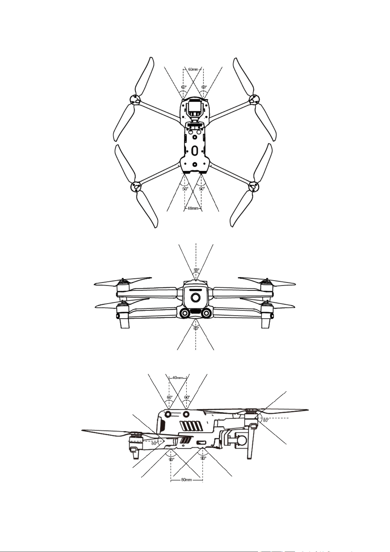
26

27
Remark
Omnidirectional obstacle sensing directions include front, back, up, down, left and right.
However, there are blind spots in the four diagonal directions. In manual flight, attention
should be paid to the surrounding environment and App prompts to guarantee safety.
Do not operate the aircraft in a complex environment where there is insufficient light, small
object (such as twig, line, net), moving object, transparent surface (such as window) or
reflected surface (such as mirror).
In the case of flight with car or other vehicles, please select a field or closed road for driving.
Never use it on highway.
Preconditions
Ensure that the aircraft is in GPS or vision positioning mode.
The aircraft shall take off when the flight LED indicator flashes green slowly or red twice.
When the GPS signal is weak or fails to meet the vision positioning requirement(e.g., when
there are small visible textures on the surface or when the aircraft flies at an altitude of more
than 12 m (36 ft) above sea level), it is necessary to be extremely careful.
The binocular vision sensation system and Starpoint positioning system are affected by the
brightness and texture of the surface below the aircraft. Avoid flying above the following
surfaces:
- Single color
- High reflectivity, such as water surface
- Particularly bright or dark surface
- Surface with frequently changing light
- Surface composed of highly repetitive pattern, such as tile
- Sound absorbing surface, such as thick carpet
- Moving surface, such as road with heavy traffic
The binocular camera lens and sensor shall be kept clean.
In order to avoid disturbing the Starpoint positioning system, do not use 40 kHz ultrasonic
device, such as ultrasonic range finder, fault detector, cleaner or welding machine.
Function description
Intelligent tracking
Intelligent tracking uses deep learning algorithms to detect six types of objects in real time:
pedestrians, cyclists, cars, trucks, boats and animals. Real-time tracking algorithms are used to
automatically track selected objects while avoiding obstacles in flight. This function can use three
modes to track objects.
Pointed flight
Pointed flight allows the user to set the flying direction of the aircraft by touching points on the
screen.
28
Gesture recognition
The main camera uses deep learning algorithms to recognize and respond to three gesture
instructions: straighten your arms up to set yourself as a target, raise your arms to take a photo,
and raise one arm to start or stop recording.
Precise landing
Regarding precise landing, the binocular vision system below the aircraft is used to record the
information at its take-off position. During the return and landing process, the visual algorithm is
used to calculate the position error between the aircraft and its take-off point in real time, so as to
control the aircraft to precisely land at its take-off position.
Safe landing
Regarding the safe landing function, the downward vision system of the aircraft is used to create a
density depth map, and the flatness and angle of the depth map are calculated to detect whether the
surface is flat enough to ensure a safe landing.
2.1.8 Extension accessories
The EVO II Enterprise can be compatible with accessories through the extension accessory
interface of the aircraft, adapting to different industry application scenarios.
Install accessory
1. Make sure that the aircraft power supply has been turned off.
2. Gently twist to take off the extension accessory interface protective cover.
3. Align screws on both sides of the accessory with the screw holes, and tighten the screws.
Disassemble accessory
1. Make sure that the aircraft power supply has been turned off.
2. Unscrew the screws on both sides of the accessory, and take off the accessory.
3. Insert both ends of the protective cover into corresponding slots.
Use accessory
The EVO II Enterprise is compatible with the following accessories:
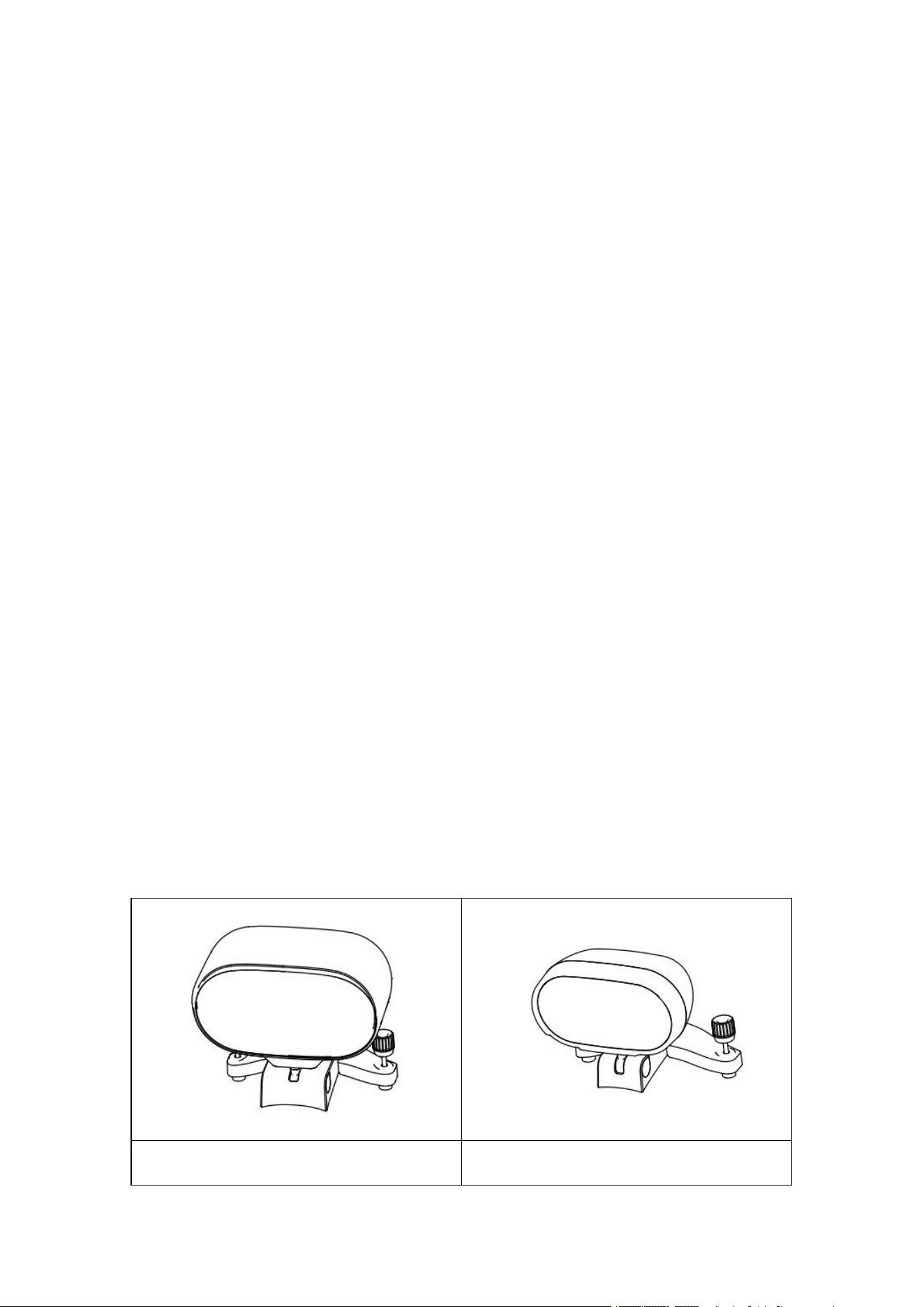
Megaphone
Searchlight
29
Night flight light
RTK module
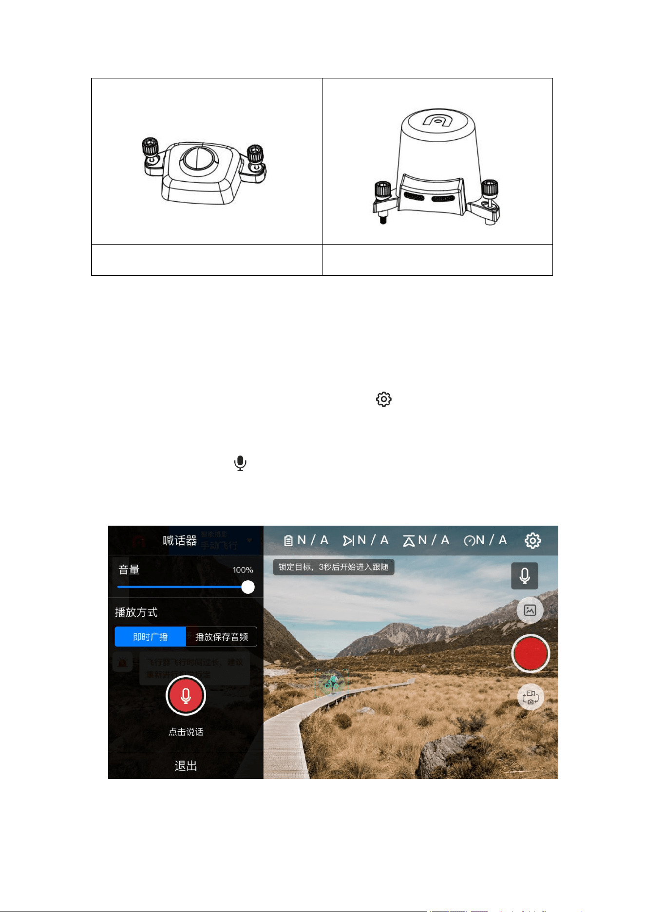
Megaphone
To realize long-distance massage transmission and loop playback of audio, and efficiently manage
on-site order in emergencies.
1. Record audio
Enter the App camera interface, select the settings button ( ) in the upper right corner, select
"Megaphone", click "Record Audio" to start recording directly, and select "Save" after recording.
2. Broadcast audio
Click the megaphone icon ( ) in the lower left corner of the camera interface, to pop up the
megaphone setting bar. The user can adjust the volume through the setting bar or select the audio
broadcast method (live broadcast/play saved audio).

30
Searchlight
To provide long-distance aerial lighting in a low-light environment to solve the lighting problem
when searching and shooting at night.
1. User searchlight
Enter the App camera interface, and click the searchlight icon ( ) in the lower left corner of the
camera interface. The user can turn off the searchlight or choose searchlights with different light
intensities (strong/medium/weak).
Night flight light
Through the constantly flashing high-intensity flashing light, the position of the aircraft is
indicated at night to avoid air traffic accidents.
1. User searchlight
Enter the App camera interface. The user can click the night flight light icon ( ) in the lower
left corner of the camera interface, and can turn off or turn on the night flight light.
RTK module
With network RTK service, centimeter-level positioning can be obtained.
1. Turn on/off RTK module
Enter the App camera interface> select the setting button ( )> RTK at the upper right corner, to
Turn on/off RTK.
2. Use with network RTK service
The network RTK server is connected to a third party to support NTRIP protocol to send and
receive differential data. Please always keep the remote controller on and connected to the Internet
during use.
1. Ensure that the remote controller has been connected to the aircraft and can access to the
Internet.
2. Enter the camera interface of Autel Explorer App> select the setting button ( )> RTK at the
upper right corner, and select the RTK service type as "Network RTK". Autel Robotics has given
users a designated network RTK package, which does not need to be purchased during the validity
period. If the package expires, users can renew the purchase by themselves.
3. Wait to establish a connection with the network RTK server, the network RTK status icon in the
setting is displayed as ( ), indicating that the network RTK data has been obtained and used.
2.1.9 Industry application
EVO Ⅱ Enterprise series can be widely used in Enterprise such as security and routing inspection .
Users can choose multiple task modes such as waypoint tasks, rectangular tasks, polygon tasks
and oblique photography through the Autel Explorer App.
Waypoint task
Add waypoints by users, set parameters and actions of the aircraft at each waypoint, and connect
the waypoints in order to form a route. After calling and executing operations, the aircraft will

31
automatically fly along the route and perform corresponding actions at each waypoint.
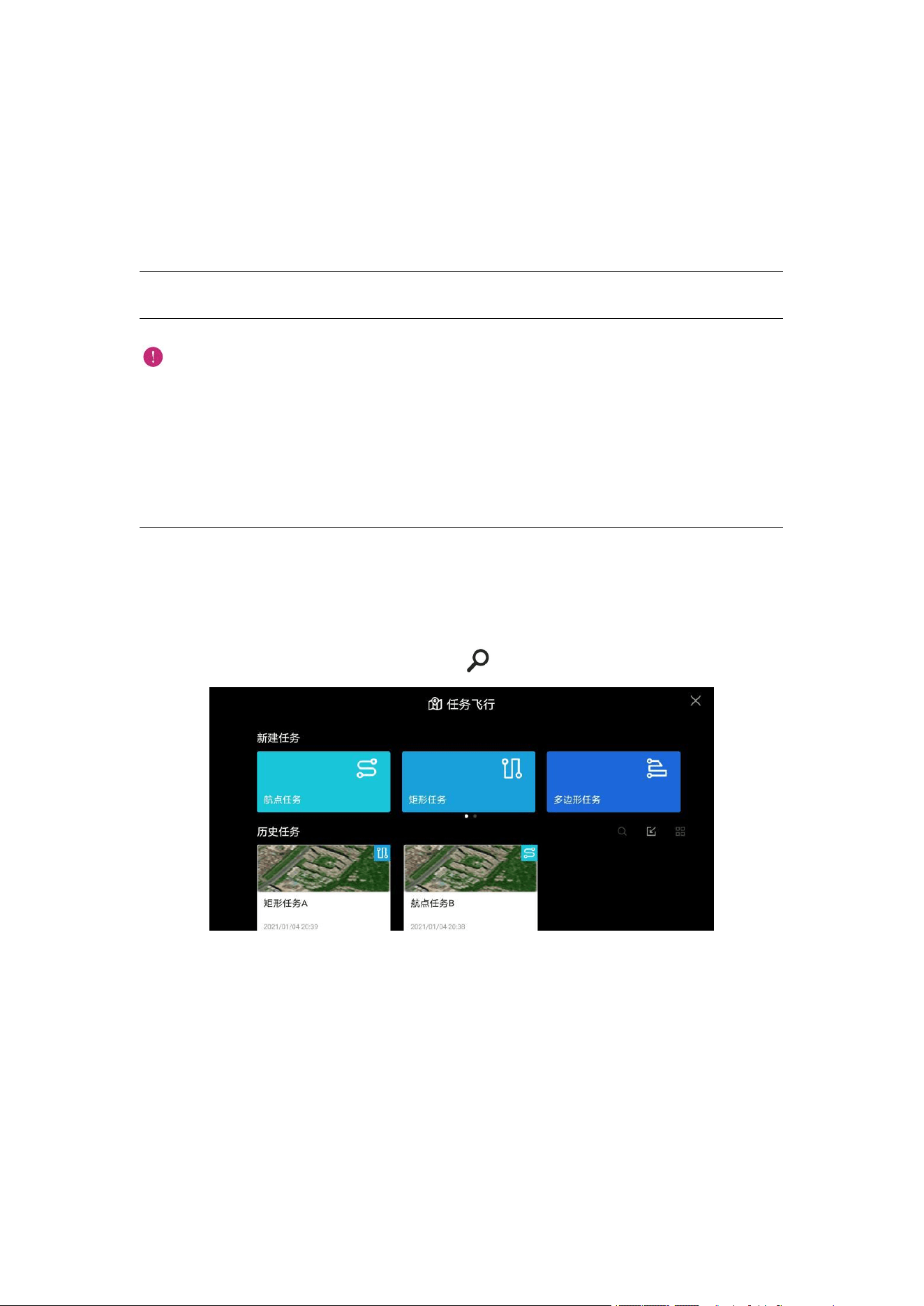
1. Click "Task Flight" on the main interface of the App, and select "Waypoint Task" to enter the
planning interface.
2. Add a waypoint on the map, and set corresponding parameters and actions of the aircraft at the
point.
Flight height: the height relative to that of the return point when the aircraft flies to this
waypoint. The aircraft will gradually adjust the flight height to the set value during the flight
to this waypoint. Click the waypoint> select "Flight Height"> slide left and right to change
the value.
Flight speed: the flight speed when the aircraft flies to this waypoint. The aircraft will
gradually adjust the flight speed to the set value during the flight to this waypoint. Click the
waypoint> select "Flight Speed"> slide left and right to change the value.
Action: Click the waypoint> select "Action"> set the waypoint action and camera action. The
waypoint action comprises "Fly Over" and "Hover".
A. When "Fly Over"is selected, camera actions of imaging, timed imaging, fixed distance
imaging, video recording start and video recording stop can be selected, or no action is
added.
B. When "Hover"is selected, camera actions of timed imaging and video recording (1-10s)
can be selected.
Gimbal pitch angle: the gimbal pitch angle (0°-90°) when the aircraft flies at the moment.
Click the waypoint> select "Action"> add camera action> slide left and right to adjust the
pitch angle.
Yawing angle: the heading direction of the aircraft flying to the waypoint. Click the the
waypoint> select "Action"> add camera action> select the yawing angle mode.
A. Along the route: the aircraft turns to a next waypoint according to a set route.
B. Manual: the user controls the course of the aircraft through the remote controller.
C. User-defined: the user can set the yawing angle of each waypoint.
Longitude and latitude: the longitude and latitude of the waypoint can be adjusted.
Associated points of interest: the main purpose of points of interest is to describe the address
of things or events, such as banks, schools, hospitals and other geographic entities. Edit
points of interest>click points of interest>associate with waypoints.
Regional task
The user can choose from three regional tasks (rectangular task, polygon task and oblique
photography). The user can set the flight parameters of the aircraft, and the system will calculate
and plan a flight route.
1. Click "Task Flight" on the main interface of the App, and select rectangular task, polygon task
and oblique photography to enter the planning interface.
2. Generate a project, you can manually move, zoom in, or zoom out the task area. After the area
is selected, click the bottom menu to modify the parameters.
Rectangular task: Generate a rectangular flight area. When the double grid is turned off, the
aircraft flies along a bow shape, which is applicable to orthophoto data acquisition. When the
double grid is turned on, it flies along a tic-tac-toe shape, which is applicable to 3D
modeling.

32
Polygon task: Generate an irregular rectangular flight area. When the double grid is turned
off, the aircraft flies along a bow shape, which is applicable to orthophoto data acquisition.
When the double grid is turned on, it flies along a tic-tac-toe shape, which is applicable to 3D
modeling.
Oblique photography: The generated route is composed of one orthographic route and four
oblique routes, applicable to accurate 3D modeling.
Rectangular task
Polygon task
Oblique photography
Flight altitude
√
√
√
Oblique height
√
√
√
Ground resolution
(GSD)
▲
▲
▲
Oblique ground
resolution
×
×
▲
Flight speed
√
√
√
Oblique speed
×
×
√
Forward overlap rate
√
√
√
Oblique forward overlap
rate
×
×
√
Sidelap rate
√
√
√
Oblique sidelap rate
×
×
√
Gimbal pitch angle
√
√
√
Oblique gimbal pitch
angle
×
×
√
Return action
Return/hover
Return/hover
Return/hover
Main rout angle
√
√
√
Double grid
√
√
×
Remark
√ - adjustable × - unadjustable ▲ - display value, unadjustable
Remark
Forward overlap rate: the overlap area rate of the ground taken by adjacent photos along the
33
flight direction; sidelap rate: the overlap rate between two adjacent flight imaging zones.
When the aircraft is shooting at a low altitude or shooting areas with uniform surfaces (such
as water, desert, fields and vegetation), increasing the overlap rate is conducive to image
splicing and processing later.
Ground resolution: it describes the actual physical size of a pixel. The smaller the value is,
the clearer the image is.
Important
If any of the following conditions are detected, the flight task ends automatically, and the UAV
will perform other operations on the basis of the following conditions.
Low battery level: A message will be popped up on the App interface to inform you that the
aircraft will return automatically.
Very low battery level: The aircraft will end the task and automatically land on the spot.
Too weak GPS signal: The UAV enters the ATTI mode and switches to manual control.
Historical task
The user can name and save the flight tasks, which are displayed in the order of creation time. The
most recently saved tasks are at the top of the list, and the earlier ones at the bottom. You can also
find corresponding historical tasks by searching ( ) file names.
34
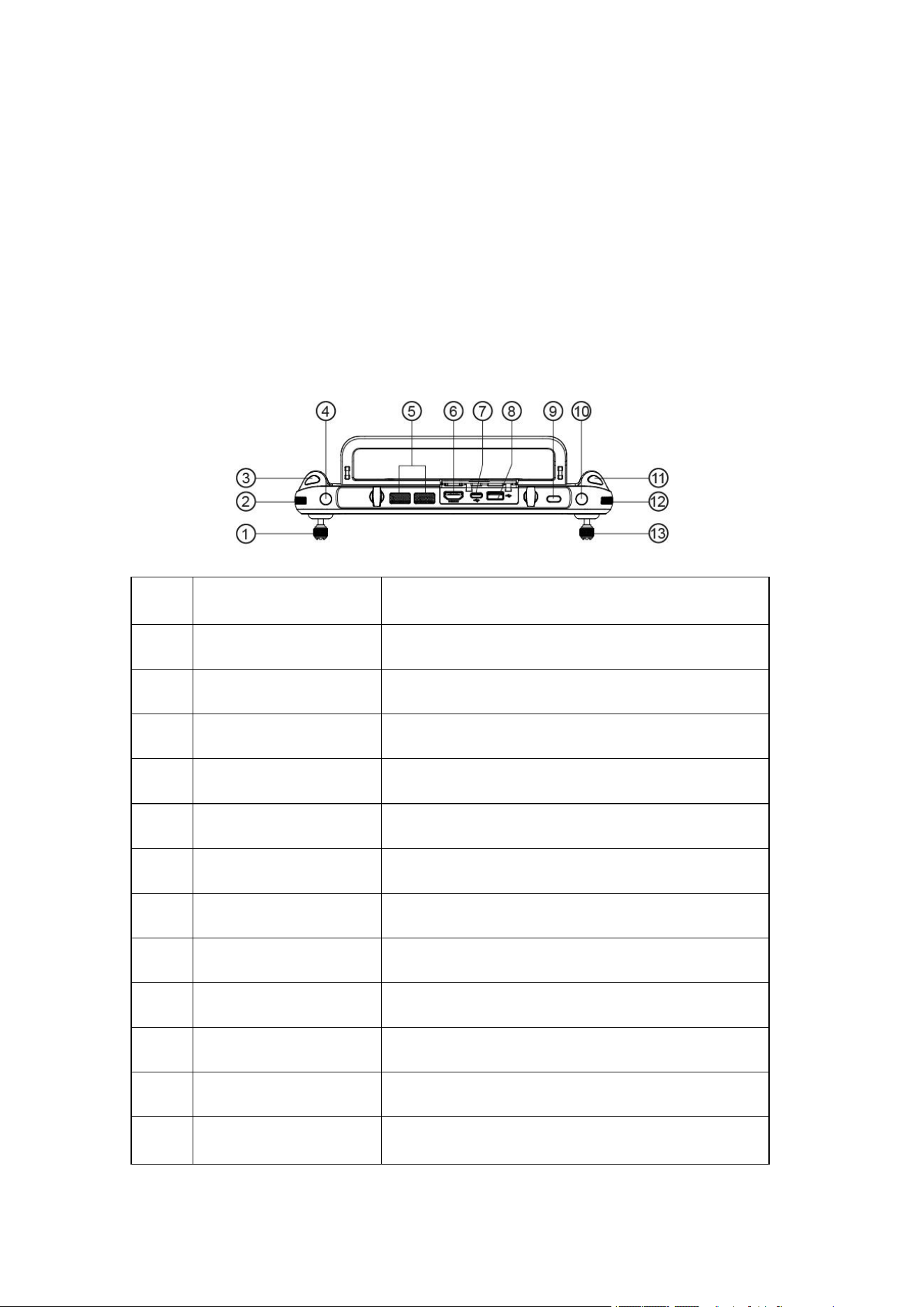
2.2 Remote controller
The Autel smart remote controller integrates portability and high reliability. A 7.9-inch
high-brightness display is not afraid of strong light, and clearly displays real-time information
about UAV flight. Due to the superior low temperature and heat dissipation performance, it is
perfectly adaptive to harsh environments. It has a long-lasting battery life of 4.5 hours, meeting
the needs of long-term outdoor operations. The customized Android system has built-in Autel
Explorer App, and supports the installation of third-party App, allowing you to create your own
exclusive operating platform.
2.2.1 Component description
1
Left rocker
To control raising, descending and heading of the
aircraft
2
Gimbal pitch thumbwheel
To adjust the pitch angle of gimbal
3
Video recording button
To start/stop video recording
4
User-defined key C1
To set functions with the Autel Explorer App
5
Air outlet
To dissipate heat of the remote controller
6
HDMI interface
To output image transmission signal
7
TYPE-C interface
To recharge the remote controller
8
USB interface
To expand 4G/5G module
9
Power supply button
Long-press for 2s to turn on/off the remote controller
10
User-defined key C2
To set functions with the Autel Explorer App
11
Shooting button
To take pictures
12
Zooming thumbwheel
To adjust the zooming multiples of camera
13
Right rocker
To control forward/backward/leftward/rightward
movement of the aircraft
35
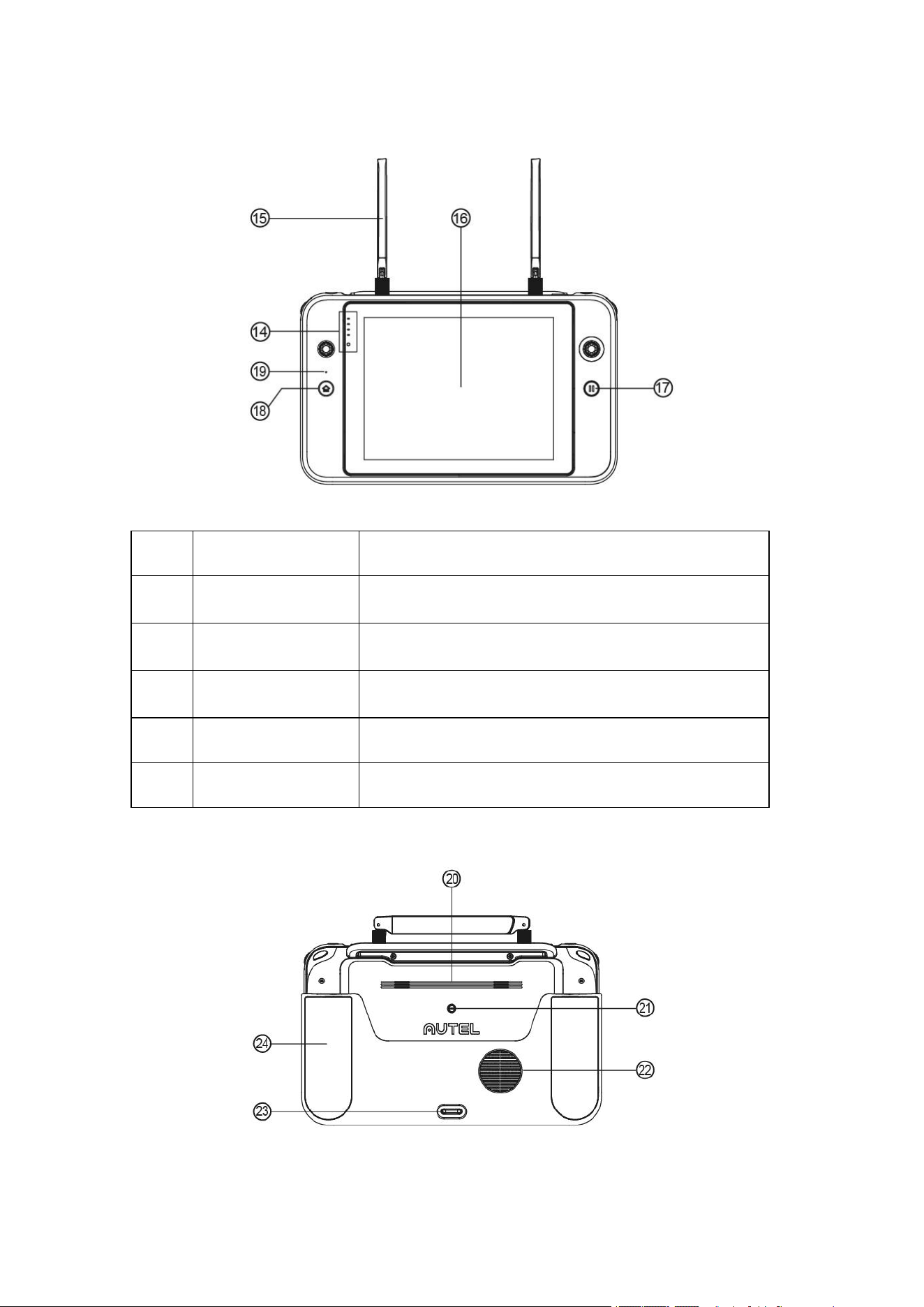
14
Battery level indicator
To display remaining remote controller battery level
15
Antenna
The frequency for communication with aircraft is
2.4GHz/5.8GHz
16
Display screen
To display image transmission screen, and support touch
control operation
17
Pause button
To control the aircraft to pause autonomous flight and hover
on the site, or recover autonomous flight
18
Return button
To order the aircraft to return to the takeoff point
19
Microphone
To receive and record sound
36
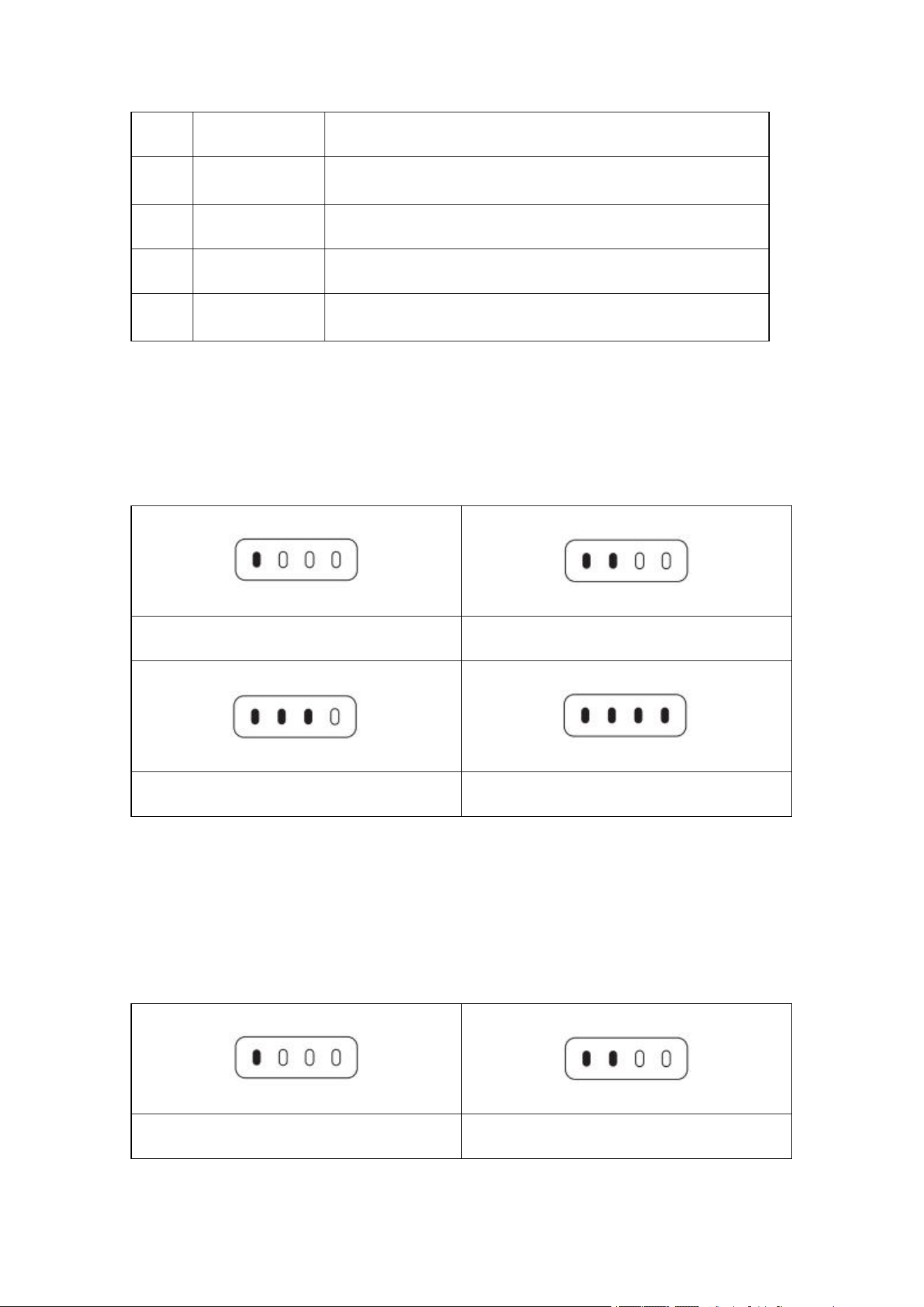
20
Horn hole
To broadcast the sound and aircraft status message
21
Standard 1/4
interface
To connect foot stool
22
Air inlet
To dissipate heat of the remote controller
23
Lower hook
To fix remote controller sling
24
Protective cover
To prevent the remote controller from external damage such as
collision and abrasion
2.2.2 Use remote controller
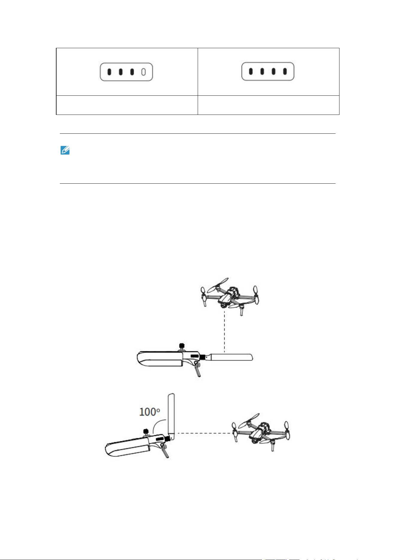
Check the battery level
Short-press the power supply button to check the remote controller battery level.
One light normally on: battery level ≥25%
Two lights normally on: battery level ≥50%
Three lights normally on: battery level ≥75%
Four lights normally on: battery level ≥100%
Turn on/off
Long-press the power supply button for 2s to turn on/off the remote controller.
Charge
Remote controller status indicator.
One light normally on: battery level ≥25%
Two lights normally on: battery level ≥50%
37
Three lights normally on: battery level ≥75%
Four lights normally on: battery level ≥100%
Remark
The indicators in the charging process flash sequentially, and are all normally on after full
charging.
Adjust antenna
Unfold the remote controller antenna and adjust the antenna position. Antennas in different
positions receive signals of different intensities. When the antenna and the back of the remote
controller are at an angle of 180° or 260°, and the antenna plane right faces the aircraft, the signal
quality of the remote controller and the aircraft can be in the optimal status. When controlling the
aircraft, be sure to keep the aircraft within the optimum communication range.

38
Remark
Do not use communication equipment of other frequency bands at the same time, otherwise
the remote controller signal may be interfered.
In actual operation, Autel Explorer prompts when the image transmission signal is poor,
please adjust the position of the antenna according to the prompt, and ensure that the When
controlling the aircraft, it is necessary to timely adjust the aircraft is in the optimum
communication range.
Frequency pairing
When purchased as a set, the remote controller and the aircraft have been in frequency pairing at
the factory, and can be used directly after activated.
In other situations, frequency pairing is carried out using the following methods.
1. Short-press the frequency pairing button next to the USB interface on the right side of the
aircraft body to make the aircraft enter into the frequency pairing state;
2. Turn on the remote control and run Autel Explorer, enter the task flight interface, click the gear
icon in the upper right corner, enter the setting menu, click "Remote Controller -> Digital and
Image Transmission Frequency Pairing> Start Frequency Pairing", and wait a few seconds until
frequency pairing succeeds.
Remote controller calibration
If the rocker is abnormal, the remote controller is recommended to be calibrated. You can calibrate
the remote controller by using Autel Explore App, or calibrated by the following steps.
1. Turn on the remote controller. Enter the App camera interface>set ( )>remote
controller>remote controller calibration. Two branched shapes and two horizontal bars show up on
the screen, representing the left and right rockers and the left and right thumbwheels respectively.
2. Rocker calibration: rush and hold the rockers in eight directions one by one until you hear a
beep.
3. Thumbwheel calibration: rotate the thumbwheel clockwise until you hear a beep. Then rotate
the thumbwheel counterclockwise until you hear a beep.
Rocker mode
This aircraft includes three rocker modes: Japanese manipulator, American manipulator and
Chinese manipulator and. You can set the rocker mode in the Autel Explorer based on your own
preference. The default manipulation mode of the remote controller is "American manipulator". At
the moment, the left rocker controls the elevation and direction of the flight, and the right rocker
controls the forward, backward, and leftward and rightward flight directions of the aircraft.
39
Chapter 3
Flight preparation
The EVO Ⅱ Enterprise series is convenient and unique in design and is fully assembled before
delivery. To ensure the safe operation of the UAV, please read the following instructions and
warnings before the first flight.
3.1 Battery preparation
3.1.1 Install aircraft battery
1. Turn off the battery power switch before installing battery.
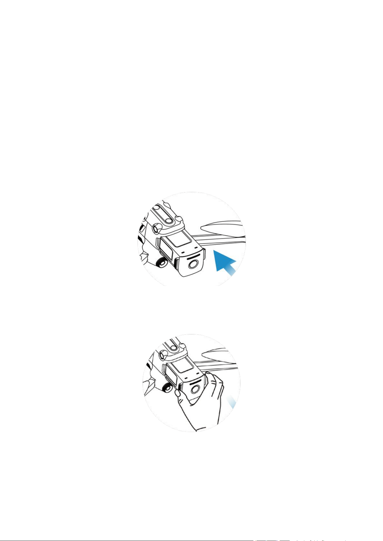
2. Insert the battery into the battery compartment. There will be clicking sound when the battery is
installed in place.
3.1.2 Disassemble aircraft battery
1. Turn off the aircraft battery power switch before taking out the battery.
2. Press the buckles at two sides of battery and slowly take out the battery.
3.1.3 Charging
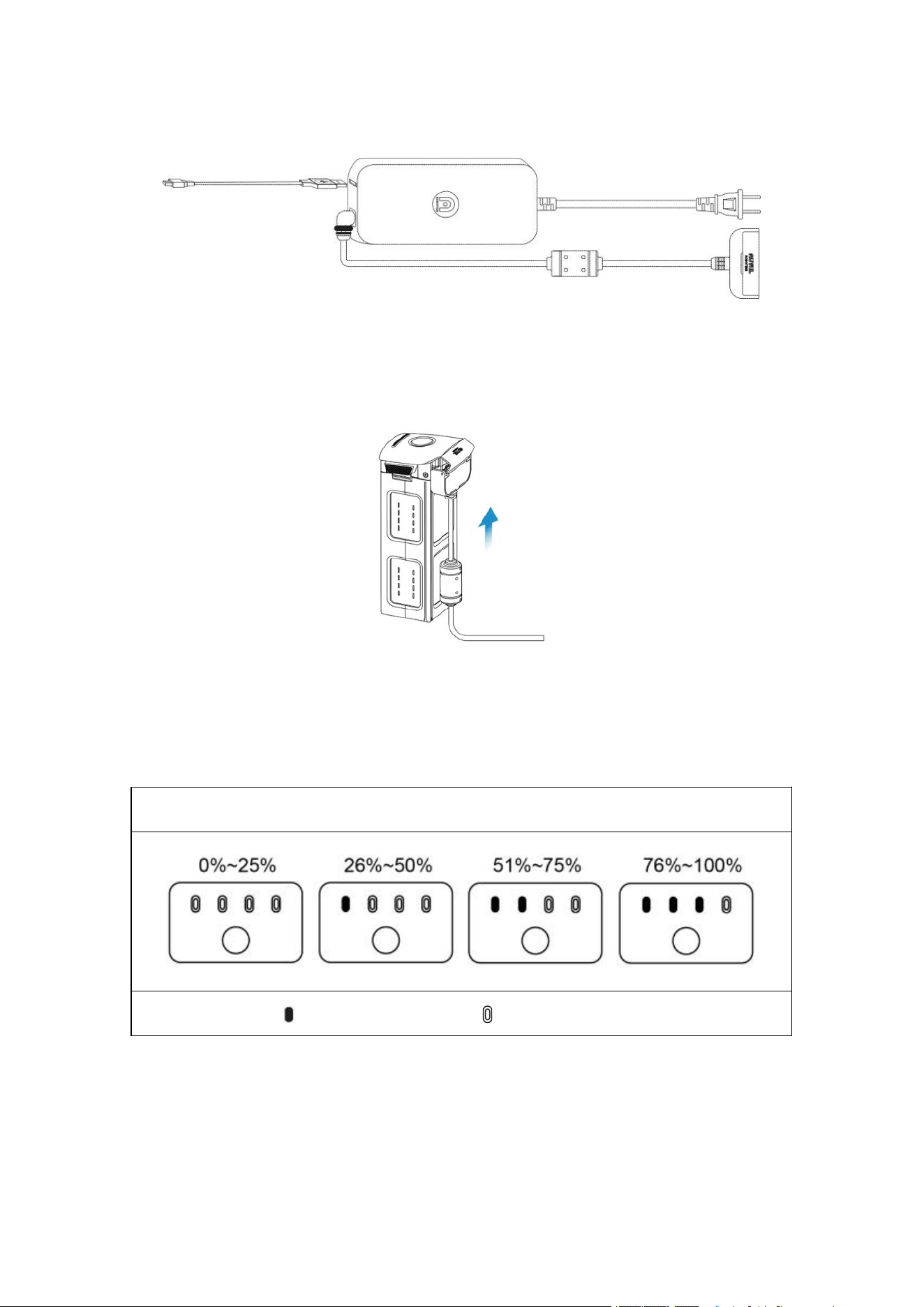
The aircraft battery and remote controller can use the charger for charging. The two connectors are
connected with the charger. As shown in the figure below, the fixed plug is connected with the
aircraft battery, and USB charge wire is used for charging the remote controller.
40
Charge the aircraft and the remote controller
1. Insert the charge wire by the following steps:
Aircraft battery: Insert the charge connector into the charge interface of the battery.
Battery level indicator: The LED indicators on the aircraft battery light up in order from left
to right to indicate the current battery level during the charging cycle, and turn off when the
battery is fully charged.
Battery level indicator status (Charging status)
- Green is normally on - Green is flashing
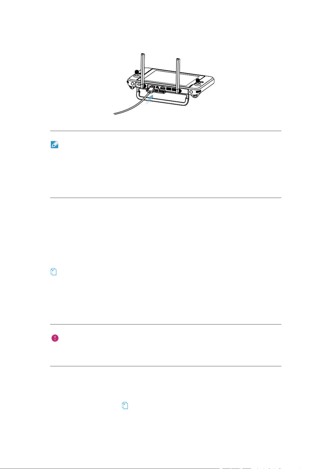
2. Remote controller: insert the Type-C power cable into the Type-C port of the remote
controller.
41
Remark
The batteries of the aircraft and the remote controller shall be always fully charged before
flying.
At most 90 minutes are required to fully charge the aircraft battery, and approximately 120
minutes are required for the remote controller.
After charging is complete, disconnect the charger from the aircraft battery/remote controller.
3.2 Remote controller preparation
3.2.1 Extend remote controller
The remote control is folded in the packing box. Please extend the antenna before use.
Antenna position adjustment
Please refer to Section 2.2.2.
3.2.2 Turn on/off remote controller
Power on/off
Press and hold the power button for 2s until you hear a short beep.
Important
Before the aircraft power switch is turned on, always turn on the remote control first.
Before the remote controller is turned off, always turn off the aircraft power switch first.
3.2.3 Aircraft and remote controller pairing
The remote controller and the aircraft have been paired in factory. If they need to be paired again,
please refer to Section 2.2.2 ( ).
42
3.3 Aircraft preparation
3.3.1 Extend aircraft
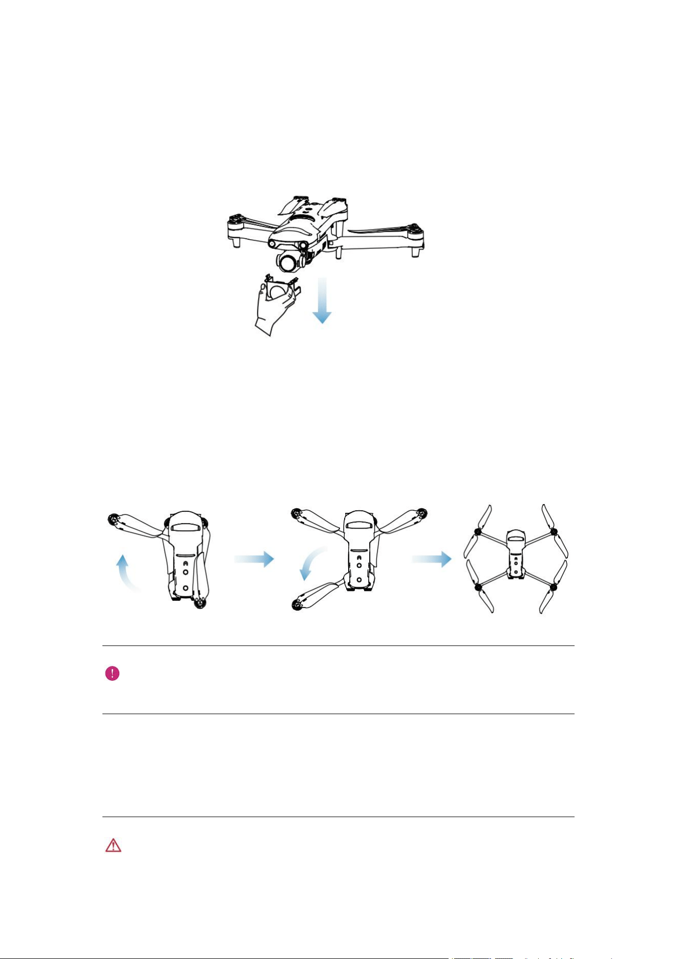
Take down and reinstall the gimbal protective cover
First take down the gimbal support, and turn on the aircraft. As shown in the figure below.
After the aircraft is used, the gimbal protective cover shall be reinstalled to prevent the gimbal
from damage.
Extend the arm and propeller
Please remember to always extend the arm of the aircraft before turning on the aircraft power
switch.
Please first extend the front arm, and then the rear arm.
Important
Before folding the arms, turn off the aircraft power switch.
3.3.2 Install the propeller
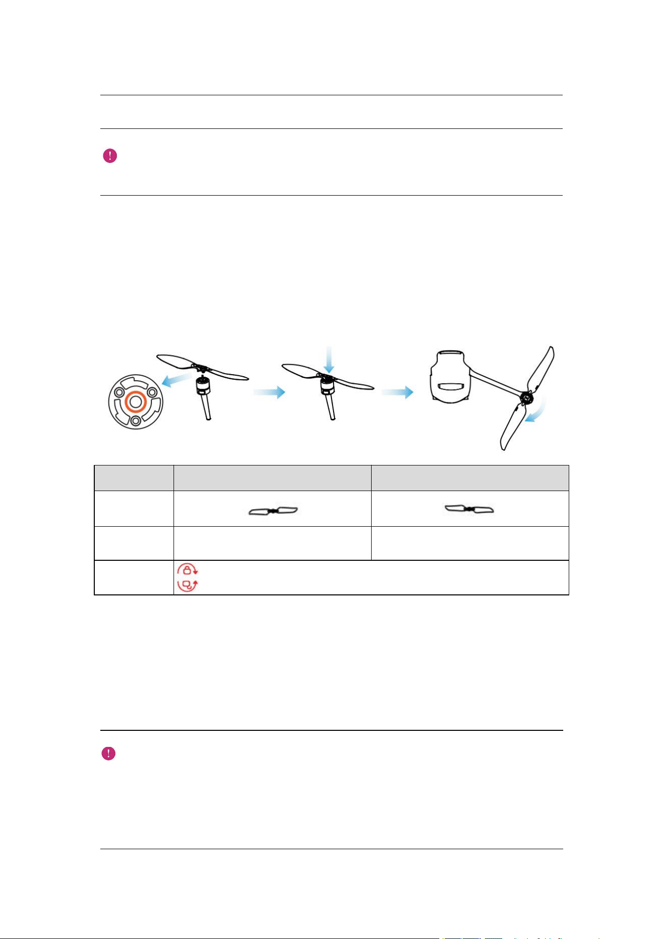
EVO II Enterprise use noise-reduction rapid-disassembled propellers.
Warning
Before installing or disassembling the propeller, please turn off the aircraft power switch.
43
Important
Wear protective gloves when installing or disassembling the propeller.
Install propeller
1. Confirm that the aircraft has been turned off.
2. Select the propeller matched for each motor.
3. Forcibly press down the propeller and rotate it along the locking direction till that it is installed
firmly.
Propeller
With white mark
Without white mark
Schematic
diagram
Installation
position
Installed to the mount with white mark
Installed to the mount without white
mark
Legend
Locking direction: rotate the propeller to tighten it as shown in the figure.
Unlocking direction: rotate the propeller to remove it as shown in the figure.
Disassemble propeller
1. Turn off the aircraft.
2. Forcibly press down the propeller and rotate it along the unlocking direction till that it is
removed.
Important
Check to confirm that each propeller has been installed firmly before flight.
Do not use the damaged propeller for flight.
It is forbidden to touch the rotating propeller or motor.
It is always necessary to take down the propeller before motor test.

44
3.3.3 Compass calibration
The compass has been calibrated in factory, with no need for calibration by user normally. If the
compass indicates the error information, or the flight direction of the aircraft is not consistent with
the control input, or the flight place is far from the calibrated distance, please carry out the
following calibration procedure.
Warning
The compass is very sensitive to the electromagnetic interference that may cause the compass
error and the flight quality reduction. If the company still fails to be used after calibration, it
is allowed to move the aircraft to other places for recalibration.
In the case of compass calibration, please pay attention to the following points:
Select an open outdoor area.
Keep away from the magnetic interference source, such as magnet or concrete reinforcement.
The calibration result may also be affected if close to a large structure.
Keep away from the underground and overhead power lines.
Never carry the ferromagnetic materials (such as key or magnetic ornaments) with you.
Keep away from all electronic devices (such as mobile device) that may interfere with the
calibration.
Calibration procedure:
1. Turn on the aircraft and remote controller, run the Autel Explorer>enter the camera
interface>click setting ( ). When the calibration process starts, the LED indicator on the back
of the aircraft turns yellow and flashes.
2. Hold the aircraft and make it horizontal, and then rotate the aircraft till the rear LED indicator
of the aircraft is normally on green.
3. Hold the aircraft and make it vertical with the head downwards, and then rotate the aircraft till
the rear LED indicator of the aircraft is normally on green.
4. Hold the aircraft with the head forwards and the side downwards, and then rotate the aircraft till
the rear LED indicator of the aircraft is normally on green.
Remark
If calibration fails, the LED indicator on the back of the aircraft turns red and is normally on.
At the moment, repeat the steps.

45
Chapter 4
Flight Operation
4.1 Check list before flight
Perform comprehensive check before flight by the following steps:
Fully charge the aircraft battery, remote controller and your mobile device.
Take down the gimbal protective cover.
Confirm that the propeller is intact and correctly installed.
Set the position of the remote controller antenna as per 2.2.2.
Pair the aircraft battery and the remote controller.
Check that the firmware has been upgraded to the latest version indeed.
Ensure that you are familiar with flight control operation.
Check whether the flight area is open without obstacle.
Check the weather, including the window and the air speed.
Check whether the camera lens and sensor of the aircraft is clean.
4.2 Flight operation
This aircraft includes three rocker modes: American manipulator, Chinese manipulator and
Japanese manipulator. Each mode has different control on the aircraft. The default mode is the
American manipulator. The user can switch in Autel Explorer App according to operation habits,
and the American manipulator is recommended for the beginner.
Basic flight
1. Place the aircraft at an open area. Stand at least 5 m (15 ft) from the tail of the aircraft.
2. Turn on the remote controller.
3. Turn on the aircraft, and wait the LED indicator at the tail to turn green and flash slowly.
4. Start the motor with the remote controller to take off.
5. Carefully navigate and manipulate the aircraft.
6. Land down the aircraft, and turn off the motor.
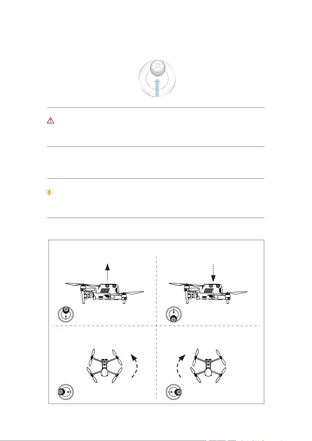
4.2.1 Motor start and aircraft takeoff (American manipulator)
As shown in figure, press the left and right rockers for 2s to start motor:
or
46
Slowly push up the left rocker:
Warning
Motor will generate heat during operation. Please operate with care.
The aircraft cannot fly when the battery level is 15% or below.
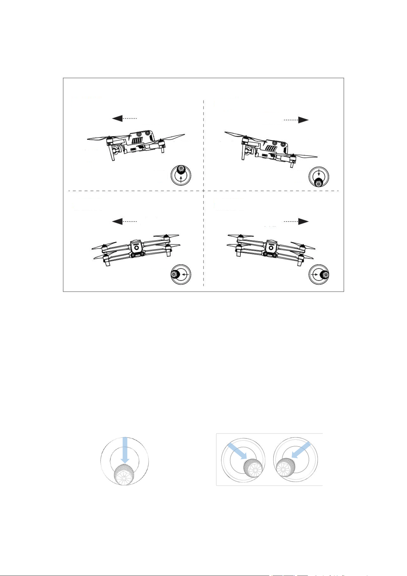
4.2.2 Manipulator control (American manipulator)
Reminding
If you are the first time to control the aircraft, please move the rocker gently till that you are
familiar with its operation.
Left rocker
Left view
Left rocker
Left view
Down
Up
Push up
Top view
Turn left
Push left
Push right
Turn right
Top view
Push down
47
Right rocker
4.2.3 Landing and motor off
EVO II Enterprise can be manually or passively landed. Steps to operate the aircraft to land down
are as follows:
Manual landing
1. Find an appropriate aircraft landing position (open and flat area).
2. When the aircraft arrive above the target position, release the rocker to make the aircraft hover.
3. Slowly push down the left rocker to land the aircraft.
4. When the aircraft lands on the ground, select one of the following methods to turn off the
motor:
or
Push the left rocker to the bottom and hold Push two rockers inwards
in the position for 2s and hold in the position for 2s
Left view
Left view
Push up
Push down
Push left
Push right
Rear view
Rear view
Leftward
Rightward
Head
Tail
Forward
Backward
Tail
Head
Right rocker

48
Remark
When the low battery level warning (25%) is displayed, the LED on the back of the aircraft
turns red and flashes, and the aircraft shall return to the safe landing point as soon as
possible.
Passive landing
When any of the following conditions are met, the fail-safe protection will be triggered and the
aircraft will automatically land from its current position.
The alarm of low battery level can be activated in a non-GPS environment.
Alarm of very low battery level is activated.

49
Chapter 5
Maintenance and service
5.1 Firmware update
In order to optimize the system performance of EVO II Enterprise UAVs, Autel Robotics will
update relevant firmware when necessary. You can download a unified firmware upgrade package
on the official website, which contains the latest versions of various firmware such as flight
controller, gimbal, camera, smart battery and remote controller. When the system detects new
firmware version, Autel Explorer APP will open a prompt box after it is connected with the
aircraft to remind you to download and install the new version.
Important
Before firmware update, please ensure that:
The aircraft motor is not powered on.
The power levels of the aircraft and the remote controller are not lower than 25%.
The SD card has enough space to store firmware files.
Download and update firmware
1. Download the firmware upgrade package from the official website of Autel Robotics:
www.autelrobotics.cn/download/8
2. Insert SD card into your computer, save the downloaded firmware package under the root
directory of SD card, and then remove the SD card from the computer.
3. Turn on your remote controller and aircraft.
4. Insert SD card into the aircraft for automatic update. User can view the upgrade process on
the flight information panel.
5. Restart the remote controller and the aircraft after update.
Important
The update takes about 15 minutes. During the update process, do not turn off the aircraft or
remote controller, start the motor, or remove the SD card from the camera.
After the upgrade, the remote controller may be disconnected from the aircraft. Please refer
to Section 2.2.2 to pair them again.
5.2 Solutions to common faults
Q1. The aircraft displays a fault during the self-inspection (the tail LED indicator is
normally on red):

50
Hardware problems are detected. Please contact the intelligent customer support of Autel
Robotics here: www.autelrobotics.cn/page/service
Q2. If the motor cannot be started, please check the following:
Whether the remote controller and the aircraft are paired.
Whether the remote controller is correctly calibrated.
Whether the aircraft battery is fully charged.
Whether the compass is correctly calibrated.
Whether the GPS can be used (when the beginner mode is started).
Q3. If the aircraft cannot take off after the motor is started, please check the following:
Whether the aircraft is in a restricted area.
Whether the aircraft is on a flat surface.
Q4. The flight time is shortened:
The most common reason for shortened flight time is the influence of low ambient
temperature, wind strength, etc.
Q5. The aircraft does not respond to the remote controller during pairing:
Confirm that there is no metallic object, mobile device or other remote controller nearby.
Q6. The video link has fault or is frequently disconnected:
Confirm that there are no sources of magnetism or signal interference around the aircraft and
remote controller.
Q7. The camera is automatically turned off in the video recording process:
Do not take out the Micro SD card from the camera, but restart the camera and wait that the
video files may be recovered as much as possible.
Q8. The video link is disconnected when the aircraft is not in the range of visibility:
Activate the auto return instruction to return the aircraft to the return point.
Q9. Cautions to use the omnidirectional binocular vision system:
Before flying, make sure that the 12 cameras are clean and free of obstructions.
Omnidirection refers to six directions, including forward, backward, leftward, rightward,
upward and downward.
There is a blind zone of 30º in the four diagonal directions of the aircraft. Please pay attention
to the surrounding environment and the safety instructions of the APP.
Obstacle detection is achieved by detecting the surface texture of the obstacle. In case of no
texture, repeated texture, pure color surface, moving object, tiny object, etc., the detection
function will not be realized normally.
Q10. The precise landing function is not realized normally:
The precise landing function is realized by detecting the texture of the ground when the
aircraft takes off with the binocular camera below.
If there is no texture on the ground, or the camera below is damaged, this function will not be

51
realized normally.
Q11. The omnidirectional binocular vision system cannot work normally:
Restart the aircraft, and check whether it can work normally or not again.
Q12. The video is obliqued during flight:
Horizontally place the aircraft and keep it steady.
Calibrate the gimbal according to the "Gimbal Calibration" function in the APP.
If the problem is still not solved, adjust the gimbal according to the instructions in the
"Gimbal Fine Tuning" function.
Q13. The lens of the binocular camera is stained:
Please wipe the lens with the glasses cloth gently. It is recommended to use the glasses cloth
provided in the packing box.
Q14. Vision errors in the flight process:
Please calibrate the binocular parameters by using the PC calibration tool which can be
downloaded from the official website.
5.3 Storage and maintenance
In order to ensure the optimal performance of EVO Ⅱ Enterprise series, please read and abide by
the maintenance instruction of this section carefully.
Store the aircraft, battery and remote controller in a clean, dry, cool and well-ventilated place.
Protect the aircraft from direct sunlight when it is not used.
Please wipe dry your two hands before operating the aircraft.
Clean the camera lens with the soft cloth with alcohol or gentle window cleanser. Do not use
any strong cleanser, detergent or chemical.
Keep the battery charger clear of other conducting materials.
Avoid the aircraft and its accessories falling, especially falling on a hard surface. Carefully
check all components after each collision or impact. Please contact the customer support of
Autel Robotics for any damage.
Only use the accessories authorized by Autel Robotics, such as charger. We will provide no
warranty for any accident due to the use of unapproved accessories.
5.4 Warranty
Autel Robotics Co., Ltd (hereinafter referred to as "the Company") promises to the original retail
buyer of the product that: under the normal use condition, if the product or its any part is certified
to have defect in material or technology, causing equipment fault, then you can, within the
warranty period (calculated from the date of delivery), carry your proof of purchase for free repair
or replacement service by the Company.
Scope of service:

52
Within the warranty period, the product has the non-human performance fault during normal
use;
The product is not disassembled without approval or modified or added as instructed by
non-official manual, or has other non-human faults;
The equipment serial number, factory label and other marks are not torn away or altered;
The effective proof of purchase, document and document number are provided;
This service is only applicable to the China mainland, and other countries and regions shall
be subject to local policies, laws and regulations.
This warranty clause will not be applied:
When the product is out of the warranty period;
When the battery has been charged for more than 200 times;
When the product doesn't use the official latest firmware;
When the fault is caused when product is used for unlawful activities;
When the product flight log has been changed or deleted without approval;
When the serial number label and waterproof mark of the product are damaged or altered;
When the product has appearance, decorative or structural (such as frame and non-operating
component) defects;
When the damage is caused because it is not installed, used and operated as instructed by the
manual;
When the product damage is caused because of the use of the self-programming or
non-official software;
When the damage is caused by the reliability and compatibility problems when the product is
used with the component of a third party other than Autel;
When the product suffers from abnormal use or environment, accident or improper handling,
unauthorized change, abuse, or improper installation, maintenance or storage;
When the product is damaged due to external factors, including but not limited to, natural
disaster, fire, water, dirt, dust, battery leakage, fuse burn-out, theft or any improper use of
power supply;
When user fails to send the product within 7 natural days after contacting Autel for warranty
service.
5.5 Customer service
This section includes the information on technical support, maintenance service, application for
replacement and spare parts.
5.5.1 Customer support
If you have any problem or question about our product, please contact the customer support of
Autel Robotics:
China
Tel: 400-800-1866
Website: www.autelrobotics.cn
North America/Europe

53
Tel: (844) 692-8835
Email: support@autelrobotics.com / support.eu@autelrobotics.com
Website: www.autelrobotics.com
5.5.2 Maintenance service
If you want to return your equipment for repair, please mail to support@autelrobotics.com or call
the customer support of Autel Robotic: 400-800-1866.
You are advisable to provide the following information:
Name
Email
Mailing address
Phone number
Product name
Complete problem description and photo
For warranty: provide the proof of purchase
For non-warranty: provide the preferred payment mode
The customer support personnel of Autel Robotic will evaluate the problem and give a reply
within 2 days.
Remark
All contents of the product may be deleted during maintenance. You are advisable to create a
backup copy for the product before delivering it for warranty service.

54
Chapter 6
Annex
6.1 Authentication information and restricted area
6.1.1 Authentication information
FCC Warning Message
Any Changes or modifications not expressly Approved by the party responsible for compliance
could void the user’s authority to operate the equipment.
This device complies with part 15 of the FCC Rules. Operation is subject to the following two
conditions:
(1) This device may not cause harmful interference
(2) this device must accept any interference received, including interference that
may cause undesired operation.
FCC Radiation Exposure Statement
This equipment complies with FCC radiation exposure limits set forth for an uncontrolled
environment. This equipment should be installed and operated with
minimum distance 20cm between the radiator & your body. This transmitter must
not be co-located or operating in conjunction with any other antenna or transmitter.
For EVO ⅡEnterprise with model EF7, SAR tests are conducted using standard operating
positions accepted by the FCC/ISEDC with the device. When used, please keep the distance
with a minimum of 10mm from the body.
Note: This equipment has been tested and found to comply with the limits for a Class B digital
device, pursuant to part 15 of the FCC Rules. These limits are designed to provide reasonable
protection against harmful interference in a residential installation. This equipment generates uses
and can radiate radio frequency energy and, if not installed and used in accordance with the
instructions, may cause harmful interference to radio communications. However, there is no
guarantee that interference will not occur in a particular installation. If this equipment does cause
harmful interference to radio or television reception, which can be determined by turning the
equipment off and on, the user is encouraged to try to correct the interference by one or more of
the following measures:
— Reorient or relocate the receiving antenna.
— Increase the separation between the equipment and receiver.
— Connect the equipment into an outlet on a circuit different from that to which the
receiver is connected.
— Consult the dealer or an experienced radio/TV technician for help.
ISEDC RSS Warning
This device complies with ISEDC licence-exempt RSS standard (s). Operation is subject to the
following two conditions:

55
(1) this device may not cause interference,
(2) this device must accept any interference, including interference that may cause undesired
operation of the device.
Le présent Appareil est conforme aux CNR d’Industrie Canada Applicables aux Appareils radio
exempts de licence.
L’exploitation est autorisée aux deux conditions suivantes:
(1) l’Appareil ne doit pas produire de brouillage, et
(2) l’utilisateur de l’Appareil doit accepter tout brouillage radioélectrique subi,
même si le brouillage est susceptible d’en compromettre le fonctionnement.
ISEDC Radiation Exposure Statement
This equipment complies with ISEDC RF radiation exposure limits set forth for an uncontrolled
environment. This transmitter must not be co-located or operating in conjunction with any other
antenna or transmitter. This equipment should be installed and operated with minimum distance
20cm between the radiator & your body.
For EVO Ⅱ Enterprise with model EF7, SAR tests are conducted using standard operating
positions accepted by the FCC/ISEDC with the device. When used, please keep the distance
with a minimum of 10mm from the body.
Any changes or modifications not expressly Approved by the party responsible for
compliance could void the user’s authority to operate the equipment.
6.1.2Diagram of restricted area
The EVO II Enterprise series can automatically identify restricted areas and avoid these areas by
default during flight. This function ensures that the aircraft complies with the legal flight area
requirements.
Flight restrictions are only enforced in some countries with mandatory legal requirements, such as
China. China is the only country that requires manufacturers to enforce flight restrictions.
Remark
Operator shall abide by all the local rules and regulations concerning flight.
The restricted area is classified into two.
Class I: main airport & low-altitude area for manned aircraft
Restricted area
A circular area centered on this area and with a radius of 2.4km (subject to government rules)
Height limit area
An annular area centered on this area and with a radius of 2.4-8km. The flight height of the
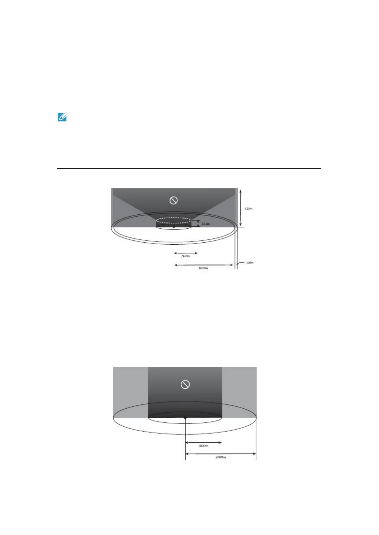
56
aircraft is limited and such height limit varies with the radius. When the radius decreases from
8km to 2.4km, the maximum flight height will decrease from 120m to 10.5m.
Warning area
APP will give a warning information when the aircraft enters the area of 8.1km from the airport.
Remark
When the aircraft enters any take-off restricted area, it will land automatically. When the
aircraft enters the altitude restricted area, its maximum allowable altitude will be lowered
accordingly. Please pay special attention to the warning message displayed by Autel
Explorer App.
Class II: Sensitive area or organization & military area & border between countries
Restricted area
A circular area centered on this area and with a radius of 1km
Warning area
APP will give a warning information when the aircraft enters the area of 2km from the airport.

57
6.2 Specifications
Aircraft
Weight (including propeller
and battery)
EVO II Pro Enterprise: 1110 g
EVO II Dual 640T Enterprise: 1136.5 g
Size (L*W*H)
508*634*111mm (including blades)
258*368*111mm (excluding blades)
Wheel base
427mm
Max. flight time (wind-free
environment)
42 minutes (excluding expansion accessories)
Hover time (wind-free
environment)
38 minutes (night flight light)
29 minutes (searchlight searchlight)
34 minutes (megaphone)
36 minutes (RTK module)
Max. horizontal flight speed
72km/h (Rage Mode)
Max. takeoff speed
8m/s (Rage Mode)
Max. landing speed
4m/s (Rage Mode)
Max. takeoff altitude
7000 m
Max. wind resistance
Grade 8
Working temperature scope
-10 to 40℃
*Working frequency
902-928MHz;
2.400GHz-2.4835GHz;
5.725GHz-5.850GHz
Transmission power
902-928 MHz
FCC: ≤30dBm
2.400-2.4835 GHz
FCC: ≤30dBm
CE: ≤20dBm
5.725-5.850 GHz
CE: ≤14dBm
Hover precision
When RTK module is equipped and RTK works normally:
Vertical: ±0.1m; Horizontal: ±0.1m
When RTK module is not equipped:

58
Vertical: ± 0.1m (vision positioning works normally);
± 0.5m (GNS positioning works normally)
Horizontal: ± 0.3m (vision positioning works normally);
± 1.5m (GNSS positioning works normally)
Gimbal
Mechanical range
Pitch: -135° to +45°
Course: -100° to +100°
Controllable range
Pitch: -90° to +30°
Course: -90° to +90°
Stability
3-axis stabilization
Max. control speed (Tilt)
300°/s
Angle vibration range (°)
±0.005°
Extension accessories
Megaphone
Size: 46*80*77 mm
Weight: 98.5 g
Interface: floating connector
Power: max. 18W
DB (ambient noise 65db): within 120dB @ 1m; 88dB @ 60m;
70dB @ 110m
Code rate: 36kbps
Adjustable angle: 0°-45°
Searchlight
Size: 48.5*72*63 mm
Weight: 77 g
Interface: floating connector
Power: max. 35W
Working scope: 30m
Adjustable angle: 0°-90°
Illuminance: FOV14°, max.: 11lux @ 30m direct light
Night flight light
Size: 39*72*34 mm
Weight: 19.5 g
Interface: floating connector
Power: 1.6W on average
Working scope: 5000m
Luminous intensity: minimum 50cd at upper hemisphere;
max. 486cd, 290cd on average
RTK module
Size: 55.5*72.5*57 mm
Weight: 59.5 g
Interface: floating connector

59
Power: about 3W
"Position accuracy:
1.5 cm + 1 ppm (vertical)
1 cm + 1 ppm (horizontal)"
Vision system
Type of video system
Omnidirectional binocular vision system
Forward vision
Accurate measurement range:0.5 - 20m
Detection range: 0.5 - 40m
Effective sensing speed:< 15m/s
Field of view:horizontal: 60°, vertical: 80°
Backward vision
Accurate measurement range:0.5 - 16m
Detection range: 0.5 - 32m
Effective sensing speed:< 12m/s
Field of view: horizontal: 60°, vertical: 80°
Upward vision
Accurate measurement range:0.5 - 12m
Detection range: 0.5 - 24m
Effective sensing speed:< 6m/s
Field of view: horizontal: 65°, vertical: 50°
Downward vision
Accurate measurement range:0.5 - 11m
Detection range: 0.5 - 22m
Effective sensing speed: < 6m/s
Field of view: horizontal: 100°, vertical:80°
Left and right vision
Accurate measurement range: 0.5 - 12m
Detection range: 0.5 - 24m
Effective sensing speed: < 10m/s
Field of view: horizontal: 65°, vertical:50°
Front effective use environment
The surface has rich textures under sufficient lighting
conditions (>15 lux, normal indoor fluorescent lighting
environment)
Above: the surface is made of diffuse reflection material and
the reflection rate is >20% (e.g. wall surfaces, trees, human,
etc.)
Below: the ground has rich textures under sufficient lighting
conditions (>15 lux, normal indoor fluorescent lighting
environment)
EVO II Pro Enterprise visible light camera
Image sensor
1" CMOS
Valid pixel
20 million

60
Field of view
82°
Lens
Equivalent focal length: 28.6 mm
Aperture: f/2.8 - f/11
Focusing range: 1 m to infinity (with automatic focusing)
ISO range
Video: 100-6400 (automatic)
Picture: 100-12800 (automatic)
Zoom
1-16 times (max. 3 times lossless zoom)
Picture taking mode
Single shot
Continuous shot: 3/5 frames
Auto exposure bracketing: 3/5 bracketing frame (under 0.7EV
offset)
Time lapse: 2s/5s/7s/10s/20s/30s/60s (JPG format);
5s/7s/10s/20s/30s/60s (DNGformat)
Pure night scene: support (in 4K JPEG format)
Long exposure: max. 8s
HDR imaging: (in 4K JPEG format)
Photographic resolution
5472*3648 (3:2)
5472*3076 (16:9)
3840*2160 (16:9)
Video format
MP4 / MOV (MPEG-4 AVC/H.264, HEVC/H.265)
Video resolution
6K 5472*3076 p30/p25/p24
4K 3840*2160 p60/p50/p48/p30/p25/p24
2.7K 2720*1528 p120/p60/p50/p48/p30/p25/p24
1080P 1920*1080 p120/p60/p50/p48/p30/p25/p24
Max. video bitrate
120Mbps
EVO II Dual 640T Enterprise thermal imaging camera
Infrared thermal imaging
sensor
Vanadium oxide uncooled infrared focal plane detector
Field of view
H33°V26°
Sensor resolution
640x512
Focal length
13mm
Wavelength scope
8-14μm

61
Precise temperature measuring
distance
2-20 m
Zoom
1-16 times
Picture taking mode
Single shot;
Continuous shot; 3, 5, 3 by default;
Timing: 2s/5s/7s/10s/20s/30s/60s, 5S by default.
Photographic resolution
Infrared mode: 640*512
Picture-in-picture: 1920*1080, 1280*720
Picture format
TIFF+JPG (with irg file)
Video format
MP4 / MOV (support H.264/H.265)
Video resolution
640*512 30fps
Temperature measuring
precision
±3℃ or ±3% of reading (which ever is larger)
@ ambient temperature -20℃-60℃
Temperature measuring scope
High gain mode: -20° to +150°
Low gain mode: 0° to +550°
EVO II Dual 640T Enterprise visible camera
Image sensor
1/2" CMOS
Valid pixel
48 million
Field of view
79°
Lens
Equivalent focal length: 25.6 mm
Aperture: f/1.8
Focusing range: 0.5m to infinity (with automatic focusing)
ISO range
Video: 100-6400 (automatic)
Picture: 100-3200 (automatic)
Zoom
1-16 times (max. 4 times lossless zoom)
Picture taking mode
Single shot
Continuous shot: 3/5 frames
Auto exposure bracketing: 3/5 bracketing frame (under 0.7EV
offset)
Time lapse: 2s/5s/7s/10s/20s/30s/60s (JPG format);
5s/7s/10s/20s/30s/60s (DNGformat)
Pure night scene: support (in 4K JPEG format)

62
Long exposure: max. 8s
HDR imaging: (in 4K JPEG format)
Photographic resolution
8000*6000 (4:3)
7680*4320 (16:9)
4000*3000 (4:3)
3840*2160 (16:9)
Video format
MP4 / MOV (MPEG-4 AVC/H.264, HEVC/H.265)
Video resolution
8K 7680*4320 p25/p24
6K 5760*3240 p30/p25/p24
4K 3840*2160 p60/p50/p48/p30/p25/p24
2.7K 2720*1528 p120/p60/p50/p48/p30/p25/p24
1080P 1920*1080 p120/p60/p50/p48/p30/p25/p24
Max. video bitrate
120Mbps
Remote controller
Max. desired signal distance
FCC: 13km, CE: 7km ( (no interference, no blockage)
*Working frequency
902-928MHz;
2.400GHz-2.4835GHz;
5.725GHz-5.850GHz
Transmission power
902-928 MHz
FCC:≤30dBm
2.400-2.4835 GHz
FCC:≤30dBm
CE:≤20dBm
5.725-5.850 GHz
CE:≤14dBm
Memory space
Built in 128GB
Video output interface
HDMI
Battery
Name: intelligent lithium-ion battery
Capacity: 5800mAh
Voltage: 11.55V
Battery type: Li-on
Energy: 67Wh
Charging time: 120 minutes
Battery life
3 hours (maximum brightness)
4.5 hours (50% of brightness)
Operating ambient temperature
-20℃ to 40℃

63
Size
303*190× 87mm (folded antenna)
303*273× 87mm (unfolded antenna)
Weight
1150G (excluding protective cover)
1250G (including protective cover)
Satellite positioning module
GPS+GLONASS+Galileo
Battery
Battery capacity(mAh)
7100mAh
Voltage (V)
11.55
Transmission power (2.4G)
13.2
Battery type
LiPo 3S
Battery energy
82Wh
Net weight (g)
365
Charging temperature range
(℃)
5- 45℃
Storage temperature & humidity
-10-30℃, 65±20%RH
Recommended storage
temperature
22-28℃
Max. charging power
consumption (W)
Charging time
90 minutes
Charger
Input
100-240V, 50/60Hz, 1.5A
Output
13.2V ⎓ 5A
5V⎓3A 9V⎓2A 12V⎓1.5A
Voltage (V)
13.2 ± 0.1V

64
Note:
* The working frequency band varies in different countries and regions.
Rated power
66W
Memory
SC card memory
Standard: 32G
Support max. 256G
Built-in memory
8G