For assembly assistance, visit haworth.com, call 800 426 8562, or email suppor[email protected]
Assembly Instructions
USB-C 22W
USB-A 18W
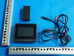
DP 5 LCD w. TOUCH and NFC (two color versions)
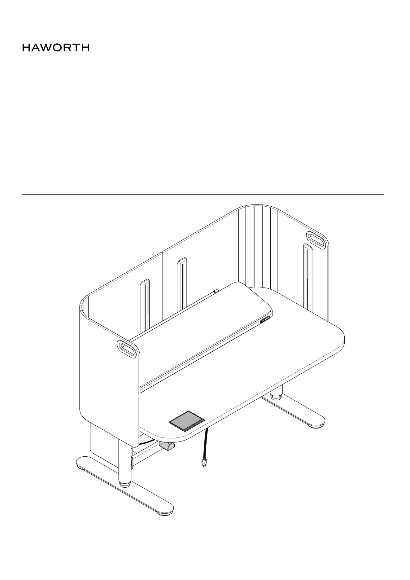
Myti Assembly Instructions
Customer Service: 800 426 8562
E.C.O. No 5-87728 Part No 6100-0xxx Rev 1 Page 2 of 49
Important Safety Instructions
Grounded
Outlet
Grounded
Pin
Grounded
Outlet Box
Figure 1
V6 Control Box
Electrical Rating:
2-leg table: 120V, 60Hz, 4.0A
Maximum load for 2 leg tables including surface: 300 lbs
For use with Myti Electric Height Adjustable Table
For Commercial Use Only
This product conforms to UL962, and is certied to CAN/CSA C22.2 No. 68
When using an electrical furnishing, basic precautions should always be followed, including the following:
Read all instructions before using this table.
DANGER - To reduce the risk of electric shock:
1. Always unplug this furnishing from the electrical outlet before cleaning or servicing.
WARNING: TO REDUCE THE RISK OF BURNS, FIRE, ELECTRIC SHOCK, OR INJURY TO PERSONS:
1. Unplug from outlet before putting on or taking o parts.
2. Close supervision is necessary when this furnishing is used by, or near children, invalids, or disabled persons.
3. Use this furnishing only for its intended use as described in these instructions. Do not use attachments not recom-
mended by the manufacturer.
4. Never operate this furnishing if it has a damaged cord or plug, if it is not working properly, if it has been dropped or
damaged, or dropped into water. Return the furnishing to a service center for examination and repair.
5. Keep the cord away from heated surfaces.
6. Do not use outdoors.
7. Do not operate where aerosol (spray) products are being used or where oxygen is being administered.
8. To disconnect, turn all controls to the o position, then remove plug from outlet.
9. WARNING: RISK OF ELECTRIC SHOCK - CONNECT THIS FURNISHING TO A PROPERLY GROUNDED
OUTLET ONLY. SEE GROUNDING INSTRUCTIONS.
10.
WARNING: RISK OF ELECTRIC SHOCK, FIRE, AND INJURY. REVIEW THE ASSEMBLY INSTRUCTIONS TO
CONFIRM THAT THE APPROPRIATE CRITICAL COMPONENTS AND ACCESSORIES ARE BEING USED WITH THE
FURNISHING.
SAVE THESE INSTRUCTIONS
This product must be grounded. If it should malfunction or breakdown, grounding provides a path of least resistance for
electric current to reduce the risk of electric shock. This product is equipped with a cord having an equipment-grounding
conductor and a grounding plug. The plug must be plugged into an appropriate outlet that is properly installed and
grounded in accordance with all local codes and ordinances.
DANGER - Improper connection of the equipment-grounding conductor can result in a risk of electric shock.
Check with a qualied electrician or serviceman if you are in doubt as to whether the product is properly grounded.
Do not modify the plug provided with the product - if it will not t the outlet, have a proper outlet installed by a
qualied electrician.
This product is for use on a nominal 120-volt circuit. The Power Module has a grounding plug that looks like the plug
illustrated in Figure 1. Make sure that the product is connected to an outlet having the same conguration as the plug. No
adapter should be used with this product.

Myti Assembly Instructions
Customer Service: 800 426 8562
E.C.O. No 5-62409 Part No 6100-0xxx Rev 1 Page 3 of 49
This device complies with Part 15 of the FCC Rules. Operation is subject
to the following two conditions: (1) this device may not cause harmful
interference, and (2) this device must accept any interference received,
including interference that may cause undesired operation.
Changes or modifications to this unit not expressly approved by the party
responsible for compliance could void the user’s authority to operate the
equipment.
NOTE: This equipment has been tested and found to comply with the limits
for a Class B digital device, pursuant to Part 15 of the FCC Rules. These
limits are designed to provide reasonable protection against harmful
interference in a residential installation. This equipment generates uses
and can radiate radio frequency energy and, if not installed and used in
accordance with the instructions, may cause harmful interference to radio
communications. However, there is no guarantee that interference will not
occur in a particular installation. If this equipment does cause harmful
interference to radio or television reception, which can be determined by
turning the equipment off and on, the user is encouraged to try to correct
the interference by one or more of the following measures:
-- Reorient or relocate the receiving antenna.
-- Increase the separation between the equipment and receiver.
-- Connect the equipment into an outlet on a circuit different from that to
which the receiver is connected.
-- Consult the dealer or an experienced radio/TV technician for help.
This device and its antenna(s) must not be co-located or operation in
conjunction with any other antenna or transmitter.
Radiation Exposure Statement
The device has been evaluated to meet general RF exposure requirement
in portable exposure condition without restriction.
Myti Assembly Instructions
Customer Service: 800 426 8562
E.C.O. No 5-62409 Part No 6100-0xxx Rev 1 Page 4 of 49
#2, #4, #5
Tools Required
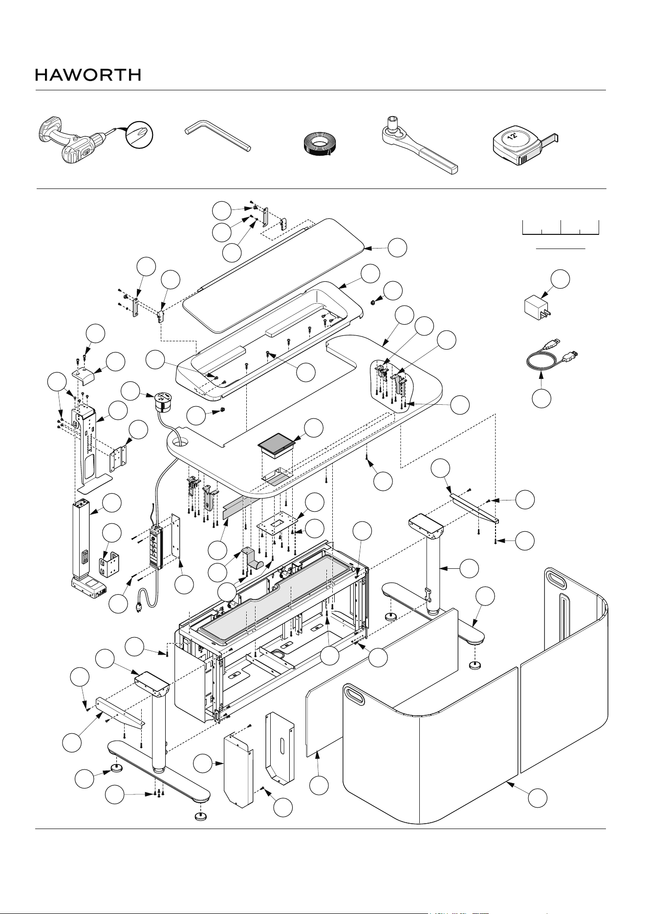
Assembly Overview
Magnetic Tip
3mm
4mm
5mm
6mm
Electrical Tape
Scale 1 : 1
011/2
1/4 1/4
F2
S200
M
L
M5
M1
M2
H
H1
S421
S423
S422
D3
D1
D
D2
L1
L1
D6
S147
M4
G
F1
S200
USB-C 22W
USB-
A 18W
C1
C2
A3
A
S199
N1
N2
S1
Q3
V
S1
P
N3
S1
S
S428
U1
R
K
S424
S428
K1
S427
S1
S1
S1
S200
S200
10mm
Myti Assembly Instructions
Customer Service: 800 426 8562
E.C.O. No 5-62409 Part No 6100-0xxx Rev 1 Page 5 of 49
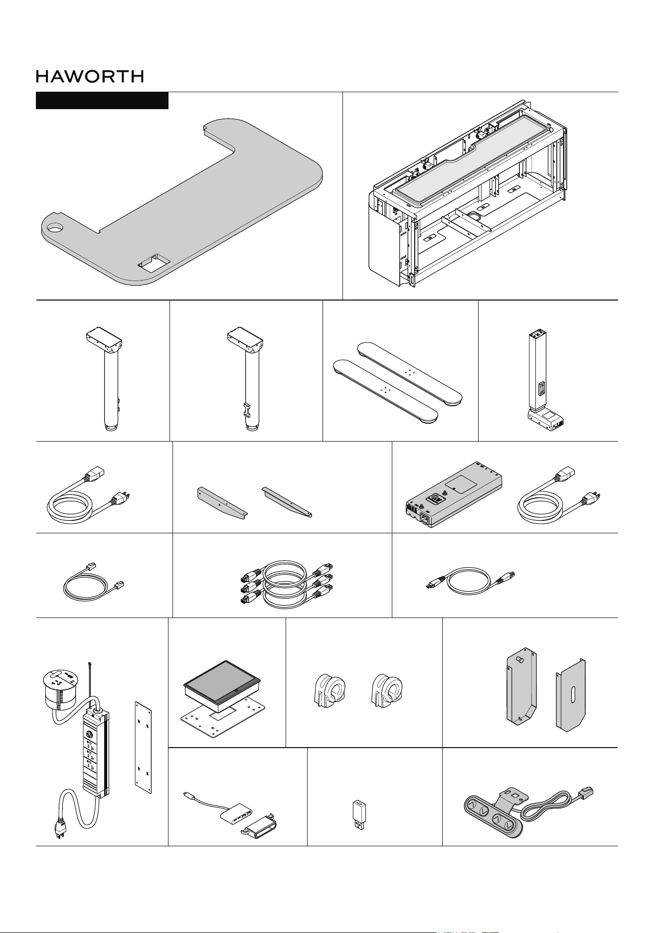
(G) Worksurface - Qty. 1
(C2) Column (Right) - Qty. 1(C1) Column (Left) - Qty. 1 (A) Leg Base - Qty. 2
(B) Frame - Qty. 1
(F) Control Box with power cord (J) - Qty. 1(J) Power Cord - Qty. 1
(CA, CB, CC) Leg Cables - Qty. 3
(D) Monitor Leg - Qty. 1
(F) Worksurface Bracket - Qty. 2
(F) RJ45 Cable - Qty. 1
(H) Power Module - Qty. 1
(H1) Bracket - Qty. 1
(F1) Left (F2) Right
(S) Cable Manager with Lid - Qty. 1(K) HMI Unit - Qty. 1
(K1) Bracket - Qty. 1
(K3) DC Cable - Qty. 1
USB-C 22W
USB-A 18W
(L1) Terrace Grommet - Qty. 2
(HH) Manual Hand Set - Qty. 1(L4) USBC to USBA
Adapter - Qty. 1
(L1) Peripheral Hub - Qty. 1
(L2) Housing - Qty. 1
PARTS LIST: COMPONETS
Myti Assembly Instructions
Customer Service: 800 426 8562
E.C.O. No 5-62409 Part No 6100-0xxx Rev 1 Page 6 of 49
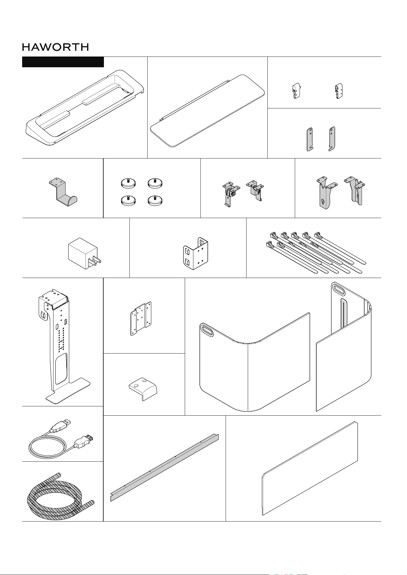
(M1) Hinge Blocks - Qty. 2(M) PET Lid
Left Right
(L) Terrace - Qty. 1
(M2) Hinge Brackets - Qty. 2
(N1) Hinge Blocks - Qty. 2
(N2) Hinge Blocks - Qty. 2(A3) Glides - Qty. 4
(D6) Monitor Cable Manager - Qty. 1 (D5) Zip Ties(V) USBC PowerAdapter - Qty. 1
(M3) Hanger - Qty. 1
(D2) Bracket - Qty. 1
(D3) Monitor Cap - Qty. 1
(P) Leg Cover - Qty. 1
(Q3) USB Extension - Qty. 1
(Q) Mesh Sleeve - Qty. 1
(U1) Frame Door - Qty. 1
(P) Screen - Qty. 2(D1) Monitor Tilt - Qty. 1
PARTS LIST: COMPONETS
Myti Assembly Instructions
Customer Service: 800 426 8562
E.C.O. No 5-62409 Part No 6100-0xxx Rev 1 Page 7 of 49
1
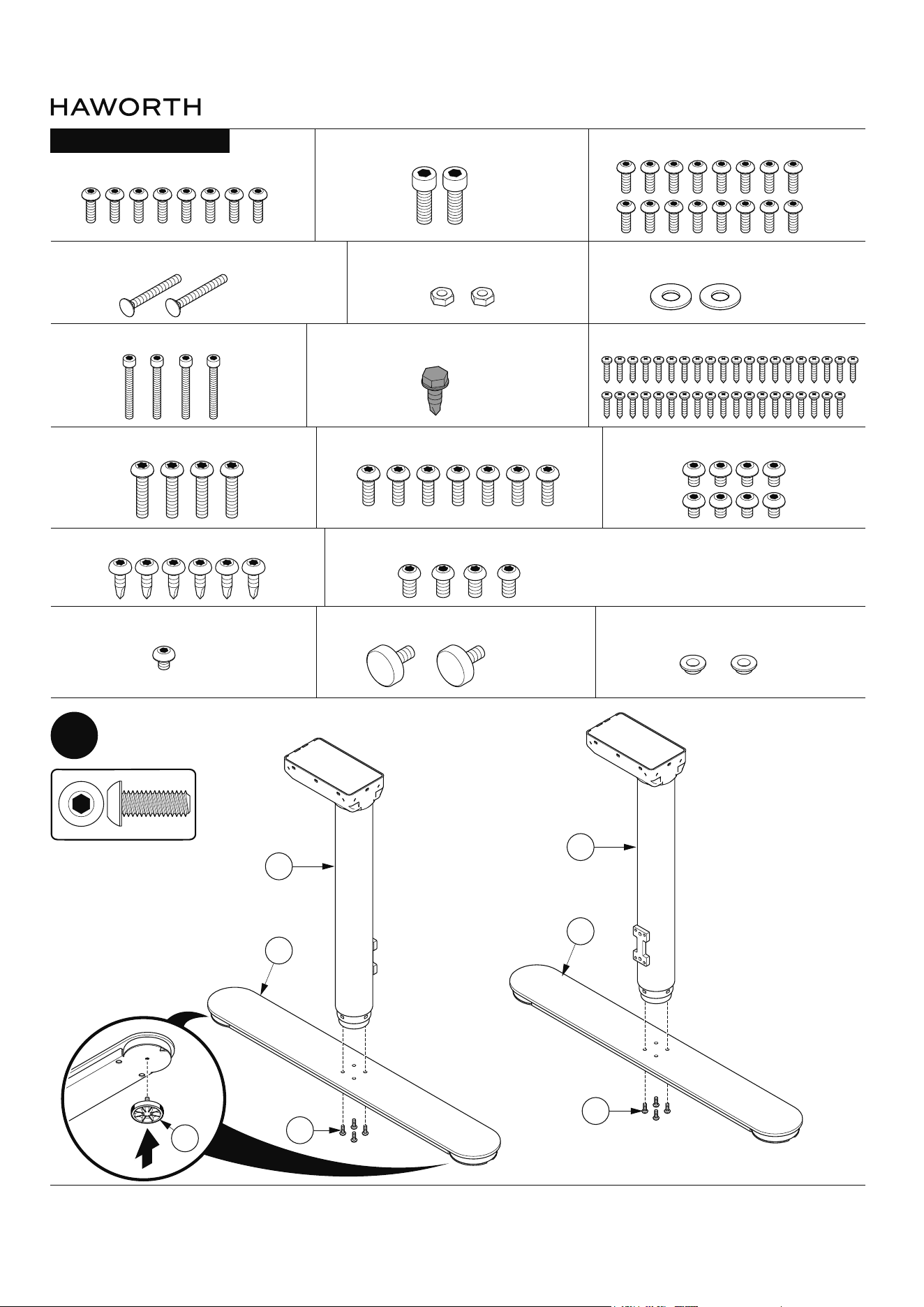
Mount table feet (A) to legs (C1 & C2) as shown
C1
S199
A
C2
S199
A
(S199) M6 X 16mm Button Head - Qty. 8
(S155) #10-24 Hex Nut - Qty. 2 (S215) #10 Flat Washer - Qty. 2
(S146) #10-32 x 3/8” Hex Head - Qty. 1
(S423) M8 X 15mm Socket Cap - Qty. 2 (S200) M6 X 10mm Button Head - Qty. 16
(S422) M6 X 8mm Button Head - Qty. 8
(S424) M5 X 12mm Button Head - Qty. 7
(S428) #10-16 x 1/2” Button Head - Qty. 6
(S420) #10-24 x 1-3/4” Carriage Bolt - Qty. 2
(S421) M4 x 35mm Socket Cap - Qty. 4 (S1) #10 x 1” Pan Head - Qty. 39
(S427) M4 x 20mm Button Head - Qty. 4
(S429) 1/4-20 x 1/4” Button Head - Qty. 1
(S147) M6 X 12mm Button Head - Qty. 4
(M5) M6 Thumb Screws - Qty. 2
(M4) M6 Plastic Bushings - Qty. 2
PARTS LIST: HARDWARE
(S199)
M6 X 16mm Button Head
A3
Myti Assembly Instructions
Customer Service: 800 426 8562
E.C.O. No 5-62409 Part No 6100-0xxx Rev 1 Page 8 of 49
2
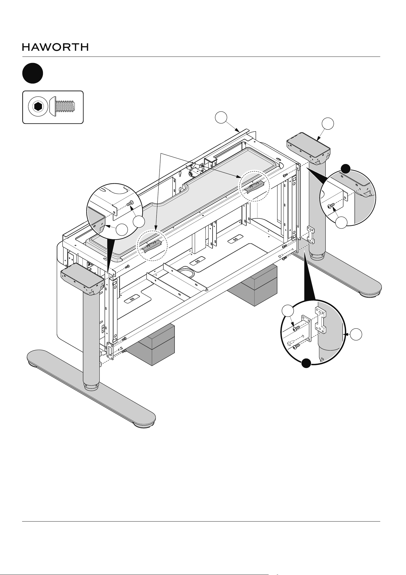
Mount legs (C1 & C2) to frame (B) as shown
B
C2
M6 X 10mm Button Head
(S200)
S200
C2
S200
S200
C1
1
2
NOTE: Raise frame (B) to
match height to assist
attaching legs (C1 & C2).
NOTE: To protect from sharp
objects cover exposed screws
with electrical tape as indicated.
Myti Assembly Instructions
Customer Service: 800 426 8562
E.C.O. No 5-62409 Part No 6100-0xxx Rev 1 Page 9 of 49
M6 X 10mm Button Head
(S200)
3
Mount monitor leg (D) to frame (B) as shown
B
D
C
D
B
S200
1
2
Myti Assembly Instructions
Customer Service: 800 426 8562
E.C.O. No 5-62409 Part No 6100-0xxx Rev 1 Page 10 of 49
B
C
4
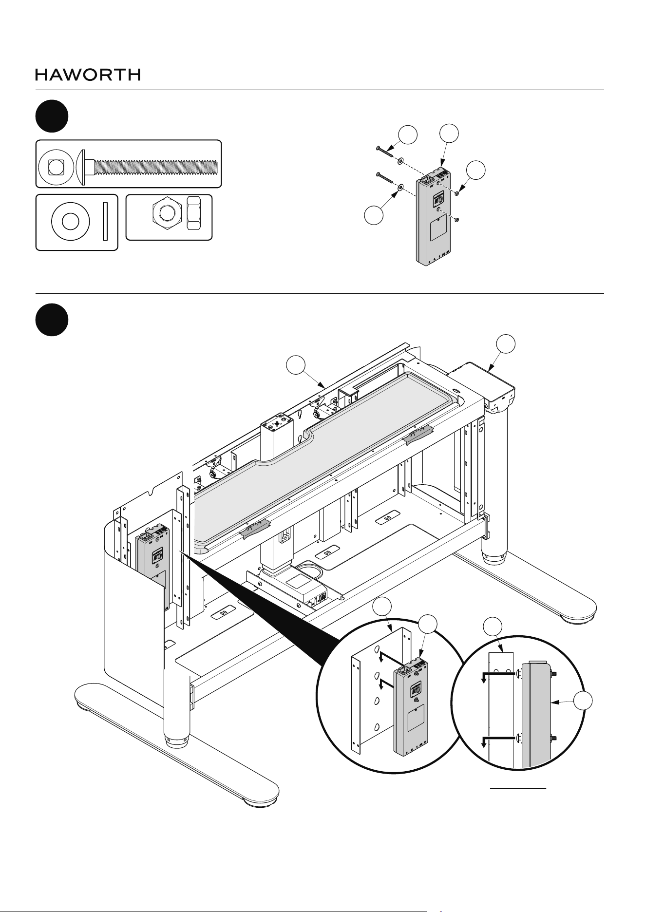
Mount control box (E) to frame (B) as shown
5
Mount control box (E) to frame (B) as shown
E
B
E
S155
S420
S215
#10-24 Hex Nut
(S155)
#10 Flat Washer
(S215)
SIDE VIEW
E
B
#10-24 x 1-3/4" Carriage Bolt
(S420)
Myti Assembly Instructions
Customer Service: 800 426 8562
E.C.O. No 5-62409 Part No 6100-0xxx Rev 1 Page 11 of 49
C
6
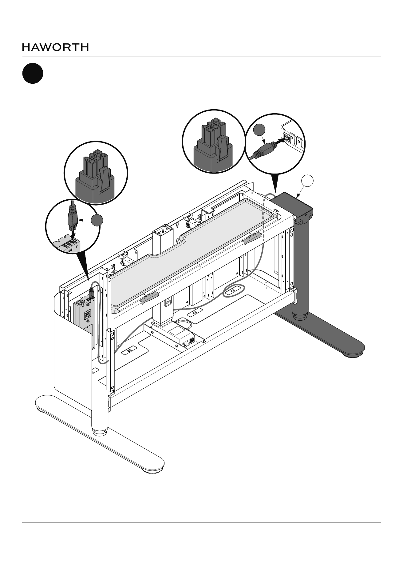
Attach right leg (C) cable (CA) as shown
NOTE: Route cable behind
monitor leg (D).
CA
CA
Myti Assembly Instructions
Customer Service: 800 426 8562
E.C.O. No 5-62409 Part No 6100-0xxx Rev 1 Page 12 of 49
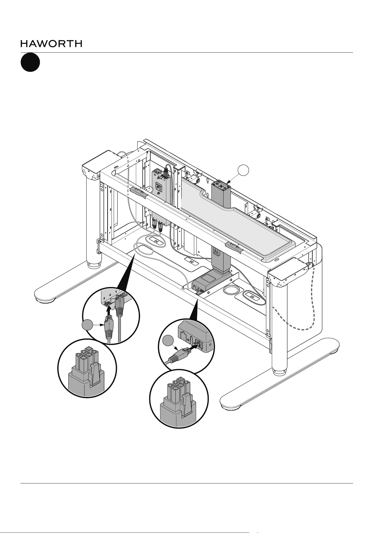
7
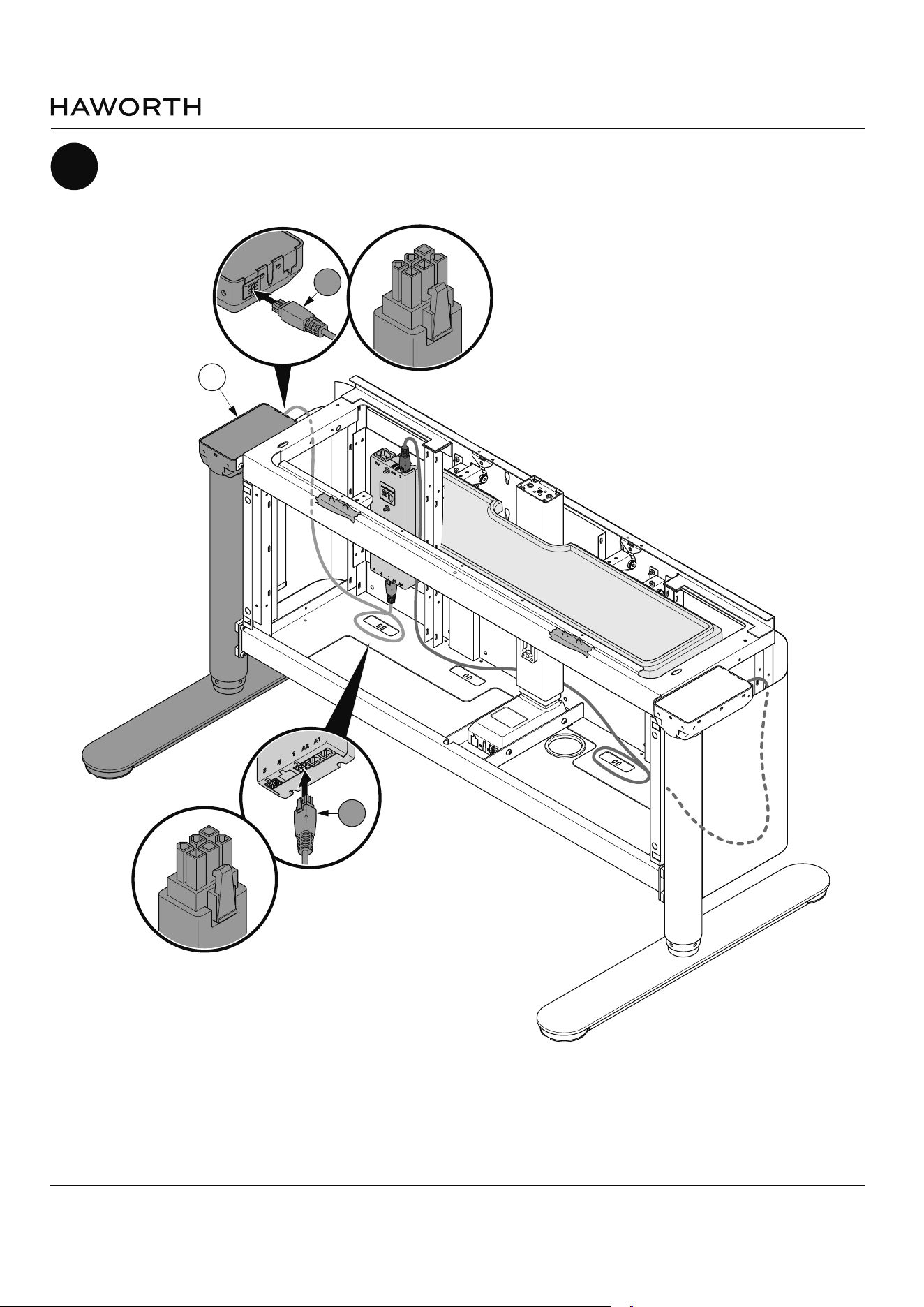
Attach left leg cable (CB) as shown
C
CB
CB
Myti Assembly Instructions
Customer Service: 800 426 8562
E.C.O. No 5-62409 Part No 6100-0xxx Rev 1 Page 13 of 49
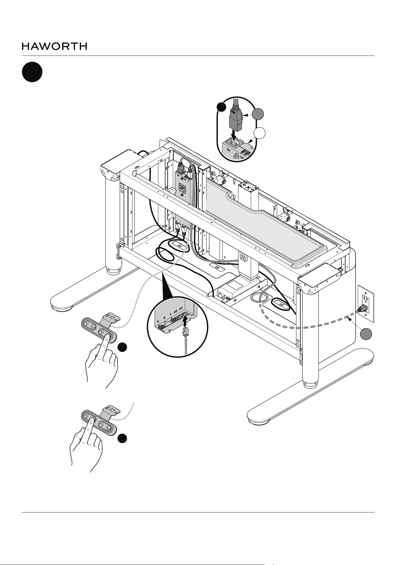
8
Attach monitor leg cable (CC) as shown
D
CC
CC
Myti Assembly Instructions
Customer Service: 800 426 8562
E.C.O. No 5-62409 Part No 6100-0xxx Rev 1 Page 14 of 49
1
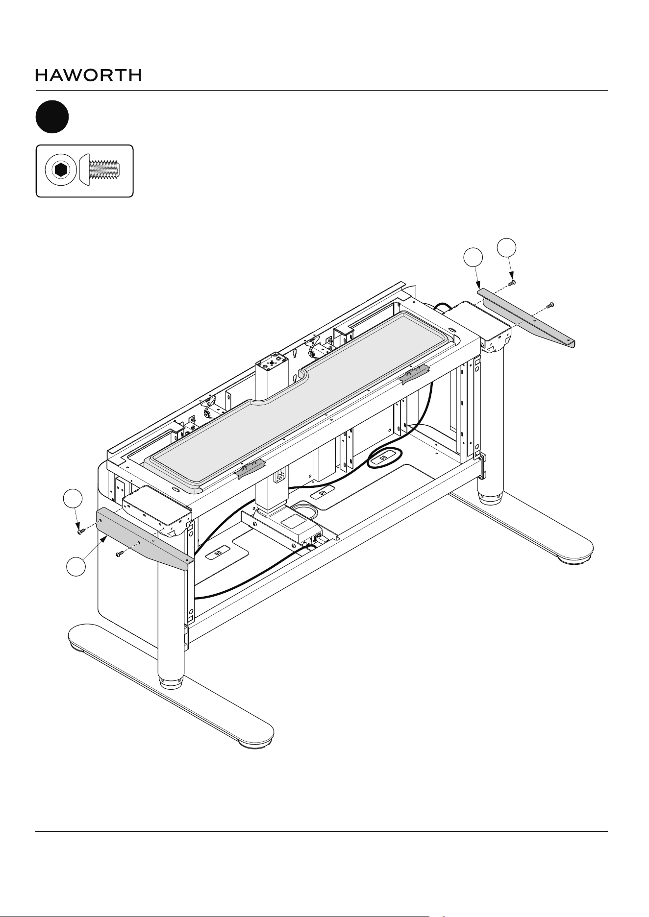
9
Attach manual hand set (HH) and connect power cord (J) to control box (E) as shown
1
E
J
J
NOTE: Temporarily plug
power into wall outlet
to initialize both
monitor and table.
NOTE: Press and hold
until table moves
slightly. Repeat for
Monitor.
2
3
MONITOR
INITIATION
TABLE
INITIATION
Myti Assembly Instructions
Customer Service: 800 426 8562
E.C.O. No 5-62409 Part No 6100-0xxx Rev 1 Page 15 of 49
F2
S200
F1
S200
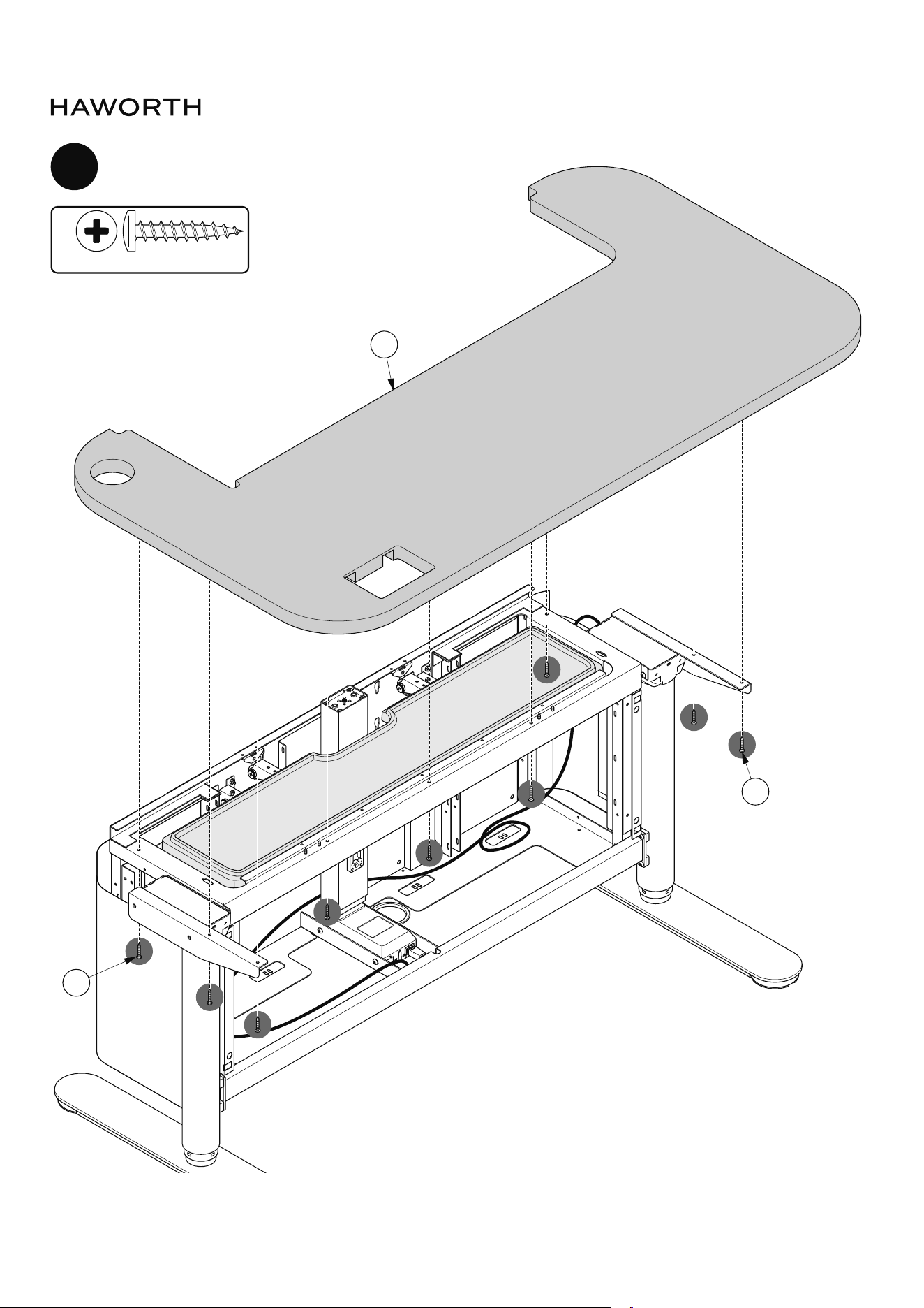
10
Attach top brackets (F1 & F2) as shown
M6 X 10mm Button Head
(S200)
Myti Assembly Instructions
Customer Service: 800 426 8562
E.C.O. No 5-62409 Part No 6100-0xxx Rev 1 Page 16 of 49
G
11
Attach top brackets (G) as shown
#10 x 1" Pan Head Screw
(S1)
S1
S1
Myti Assembly Instructions
Customer Service: 800 426 8562
E.C.O. No 5-62409 Part No 6100-0xxx Rev 1 Page 17 of 49
13
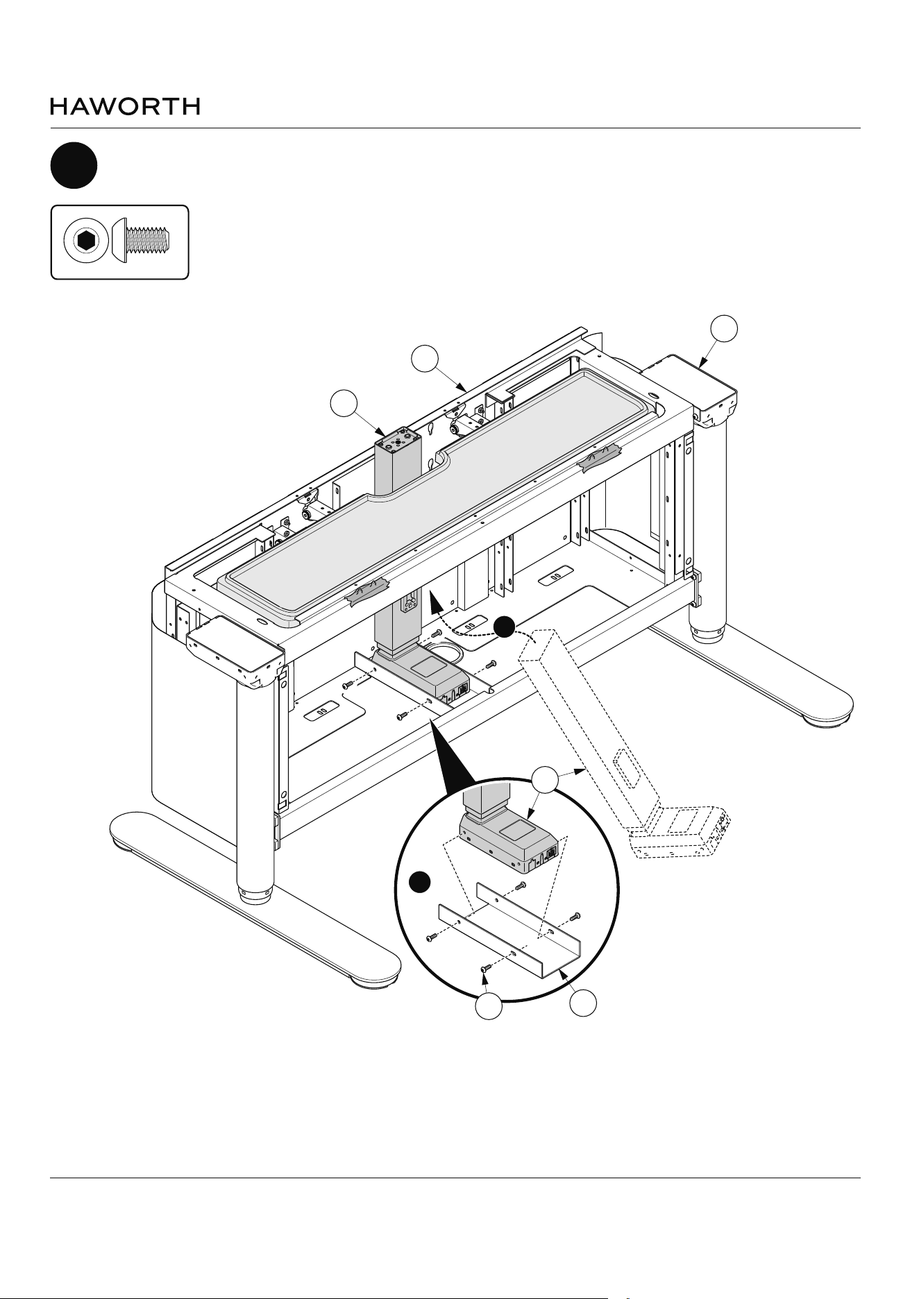
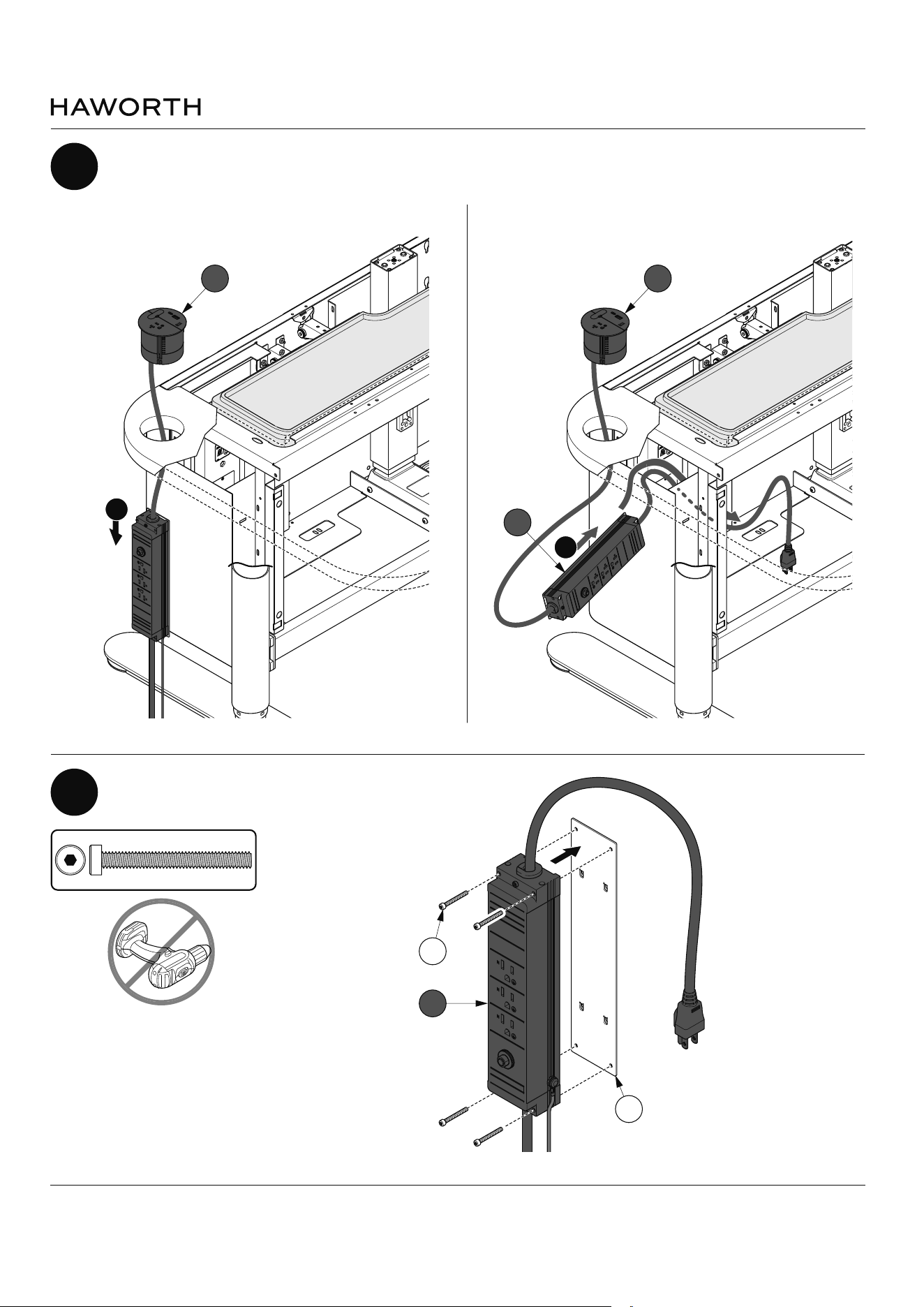
Attach bracket (H) to power module (H) as shown
H
H1
S421
H
12
Route power module (H) through top (G) as shown
H
USB-C 22W
U
SB-A
18W
1
H
USB-
C
22W
U
SB-A
18W
2
M4 x 35mm Socket Cap
(S421)
NOTE: No power
tools.
Myti Assembly Instructions
Customer Service: 800 426 8562
E.C.O. No 5-62409 Part No 6100-0xxx Rev 1 Page 18 of 49
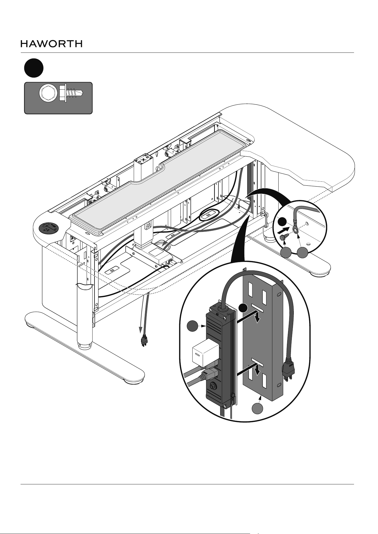
14
Attach power module (H) and route as shown
USB-C 22W
USB-A 18
W
1
H
2
H3
S430
H2
#10-32 x 3/8" Self Drilling
Hex Head Washer
(S430)
Myti Assembly Instructions
Customer Service: 800 426 8562
E.C.O. No 5-62409 Part No 6100-0xxx Rev 1 Page 19 of 49
USB-C 22W
USB-A 18W
USB-C 22W
USB-A 18W
USB-C 22W
USB-A 18W
USB-C 22W
USB-A 18W
USB-C 22W
USB-A 18W
USB-C 22W
USB-A 18W
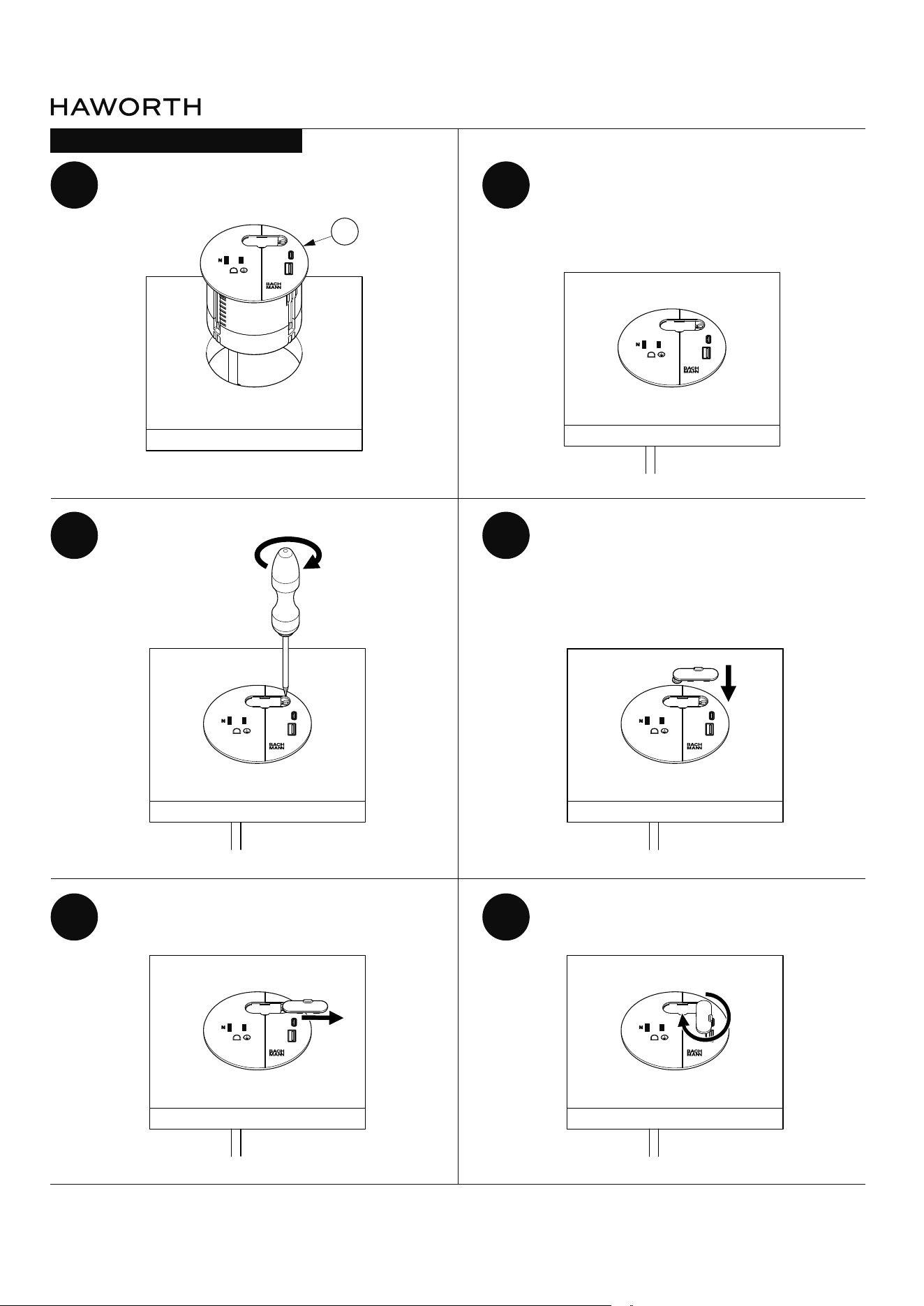
H
BACHMAN POWER UNIT ASSEMBLY
1 2
3 4
5 6
Myti Assembly Instructions
Customer Service: 800 426 8562
E.C.O. No 5-62409 Part No 6100-0xxx Rev 1 Page 20 of 49
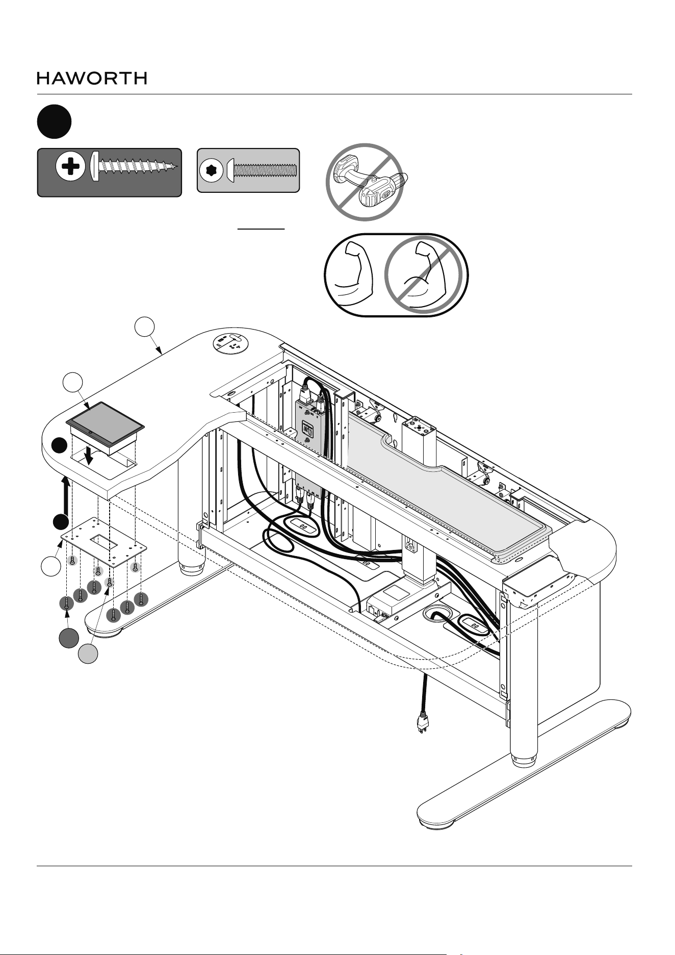
1
NOTE: DO NOT
over tighten plastic
screws (S129).
15
Install plate (K1) and then insert HMI unit (K) in top (G) as shown
G
USB-C 22W
U
SB-A 18W
#10 x 1" Pan Head Screw
(S1)
K1
S1
S427
K
2
M4 x 20mm Button Head
(S427)
Myti Assembly Instructions
Customer Service: 800 426 8562
E.C.O. No 5-62409 Part No 6100-0xxx Rev 1 Page 21 of 49
16
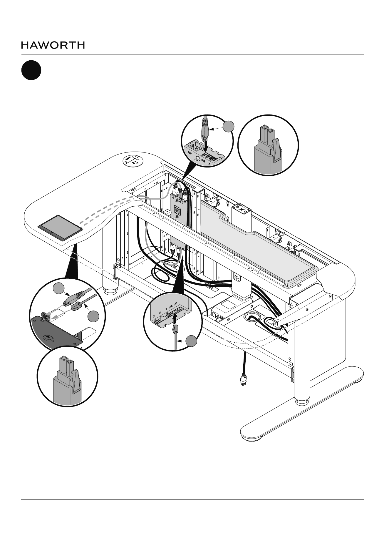
Attac DC cable (K3) and RJ45 cable (K4) as shown
USB-C 22W
U
SB-A 18W
K3
K3
K4
K4
Myti Assembly Instructions
Customer Service: 800 426 8562
E.C.O. No 5-62409 Part No 6100-0xxx Rev 1 Page 22 of 49
17
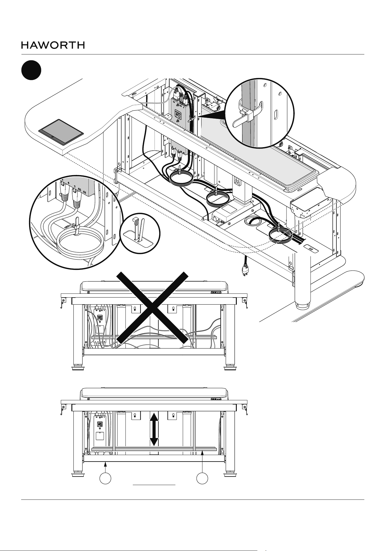
Organize cables and zip tie (example below) as shown
NOTE: Cables are routed and secured
to avoid interference or become
entangled with the monitor close out
as it moves up and down.
FRONT VIEW
B B5
Myti Assembly Instructions
Customer Service: 800 426 8562
E.C.O. No 5-62409 Part No 6100-0xxx Rev 1 Page 23 of 49
18
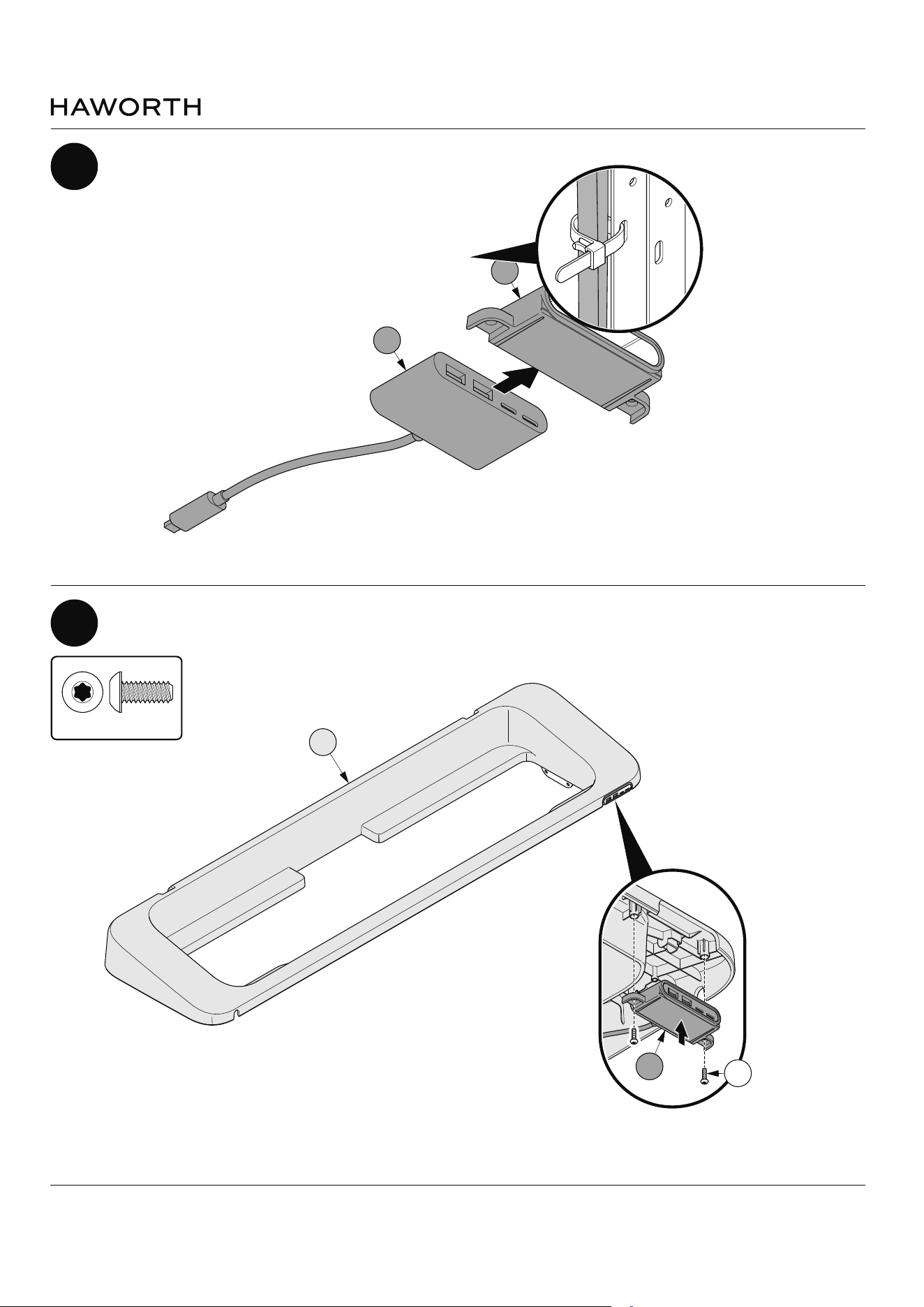
Insert peripheral hub (L1) in to housing (L2) as shown
L
L1
L2
L2
S424
19
Attach peripheral hub assembly (L2) to terrace (L) as shown
M5 X 12mm Button
Head Screw
(S424)
Myti Assembly Instructions
Customer Service: 800 426 8562
E.C.O. No 5-62409 Part No 6100-0xxx Rev 1 Page 24 of 49
20
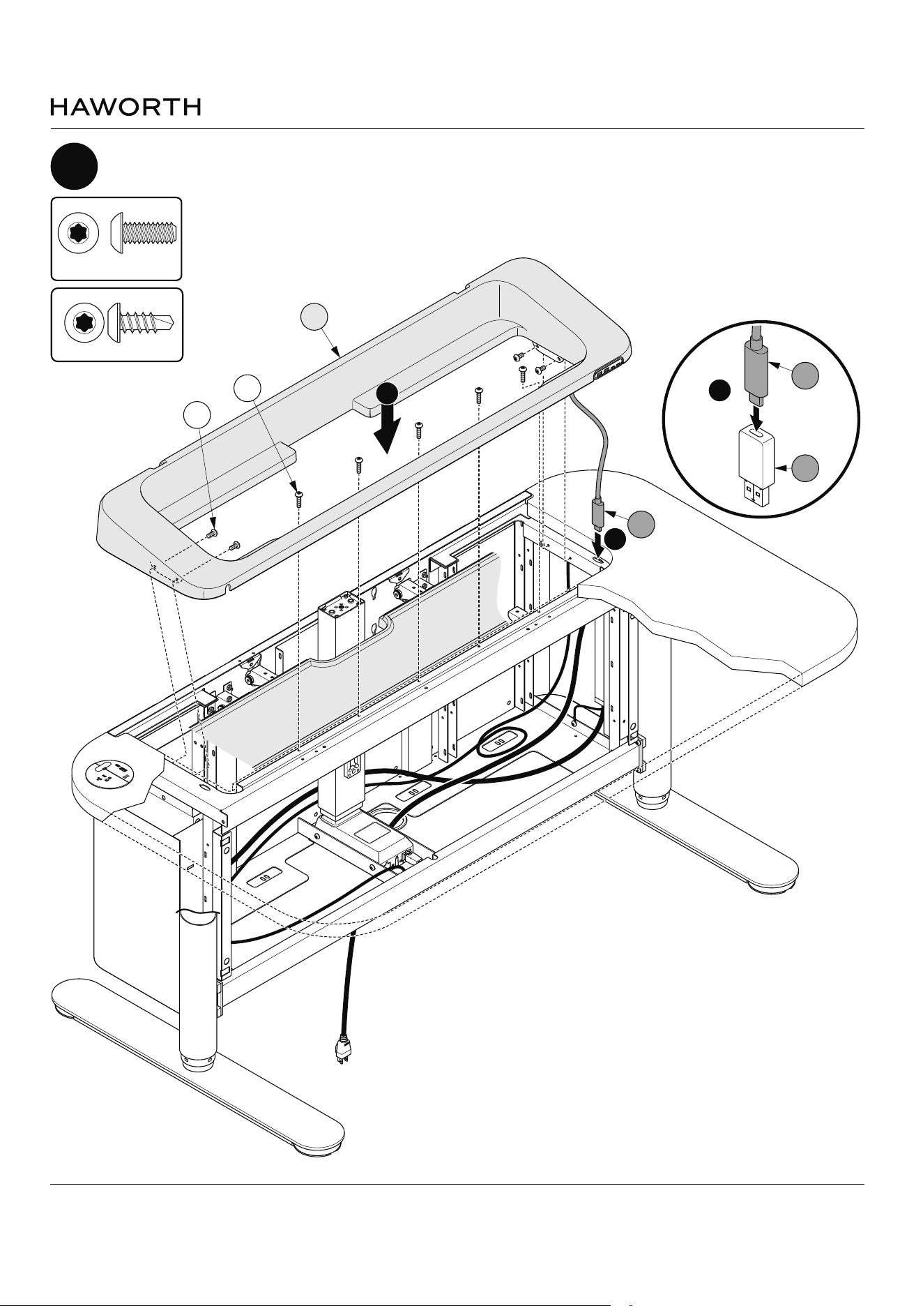
Route cord (L1) through the slot and attach terrace assembly (L) as shown
USB-C 22W
USB-A 18W
1
L1
3
L1
L4
L
2
M5 X 12mm Button
Head Screw
(S424)
S428
S424
#10-16 x 1/2" Screw
(S428)
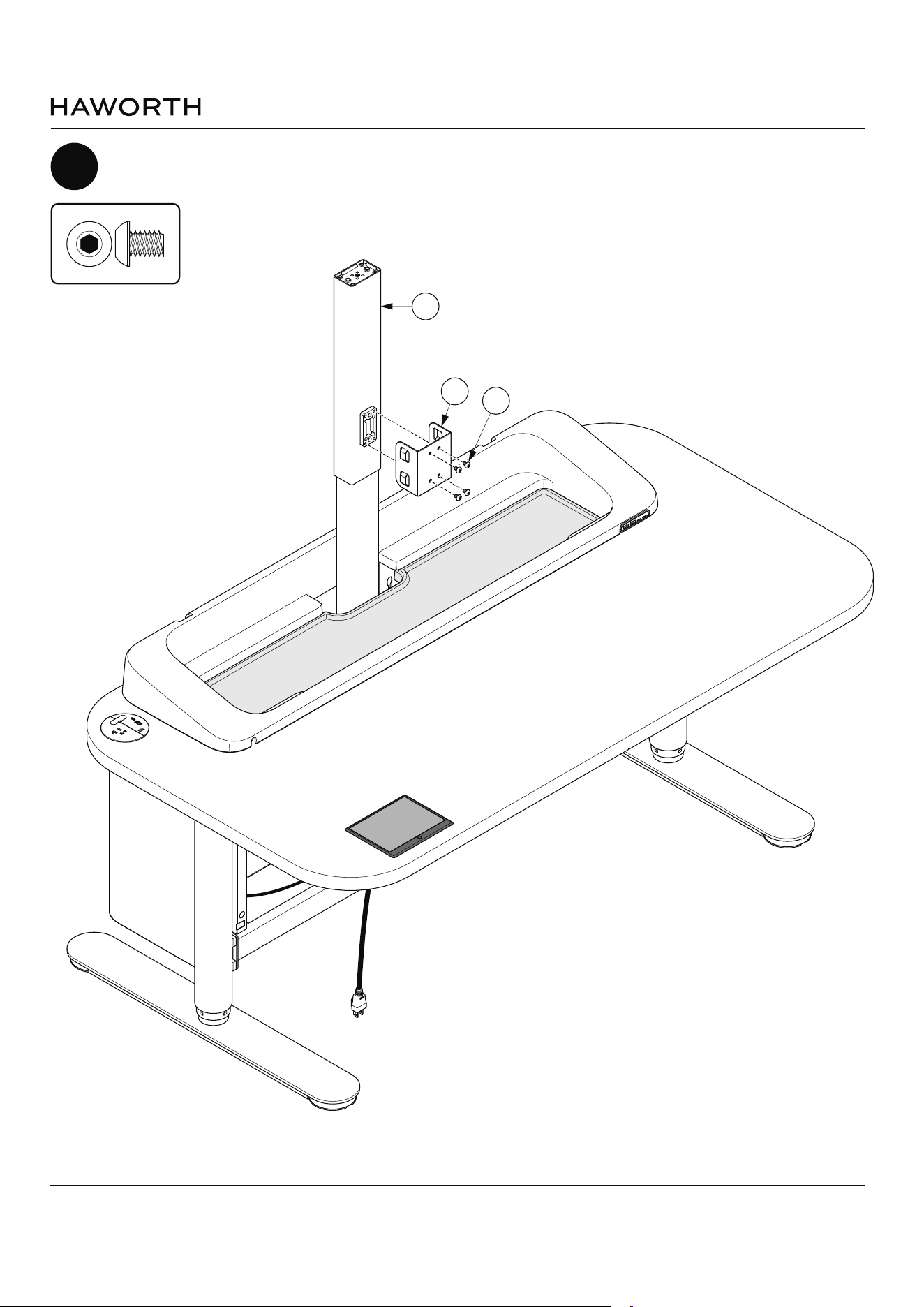
Myti Assembly Instructions
Customer Service: 800 426 8562
E.C.O. No 5-62409 Part No 6100-0xxx Rev 1 Page 25 of 49
21
Attach cable manager bracket (D5) as shown
USB-C 22W
USB-A 18W
D
D6
S422
M6 x 8mm Button Head
(S422)