
Boost Your Bars
User Manual
Mate Plus Series
4K Mate Plus
4K Mate Plus Pro
10K Mate Plus
10K Mate Plus Pro
(F10GTI-5S-IOT)
(F10GTI-5S-IOT.Pro)
(F15GTI-5S-IOT)
(F15GTI-5S-IOT.Pro)
Package Content
Introduction
Pre-Installation Instructions
light pattern
APP Assisted Installation
LCD Assisted Installation
Quick Troubleshooting Guide
Technical Specications
Authorized Accessories List
FCC and IC Statements
Return and Warranty Policies
01
03
04
12
13
29
43
46
47
48
51
CONTENTS
01
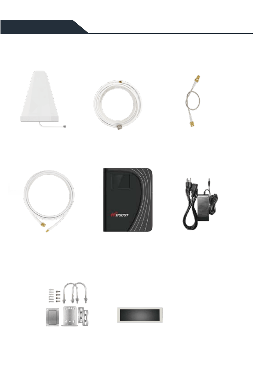
Package Content
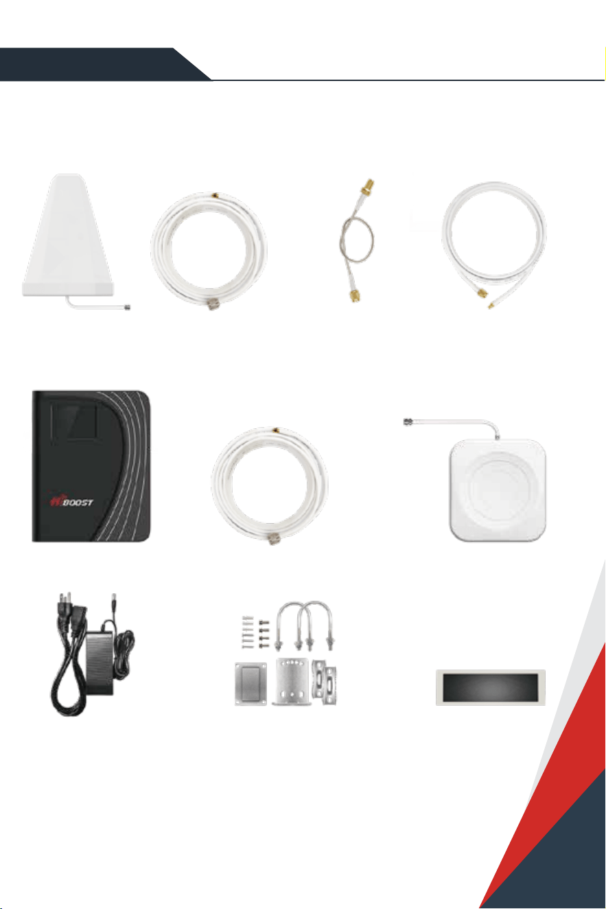
HIBoost 4K/10K Mate Plus
Outdoor Antenna
Outdoor Cable
49.2ft NM-SMAM SMA-Male to SMA-Female
(No drilled hole)
are all provided to protect connetctions
Outdoor Cable to Booster
16.4ft SMAF-SMAM
Booster Power Supply
Accessories for main parts Waterproof tape
Through-Window Cable
02
Package Content
NOTE: Available accessories can be purchased through HiBoost.com
Warning: Un-authorized antennas, cables, and/or coupling devices are prohibited by new FCC
rules. Please contact FCC for details: 1(888)-CALL-FCC
HiBoost 4K/10K Mate Plus Pro
Outdoor Cable to Booster
16.4ft SMAF-SMAM
Booster
Power Supply
are all provided to protect connetctions
Accessories for main parts Waterproof tape
Outdoor Antenna
Outdoor Cable
49.2ft NM-SMAM
Indoor AntennaIndoor Cable
30ft NM-SMAM
SMA-Male to SMA-Female
(No drilled hole)
Through-Window Cable
03
Introduction
Thanks again for purchasing HiBoost cell Booster. The HiBoost Mate Plus/Pro series is a collection of
precision-engineered products that improve cellular reception inside of homes and businesses by
amplifying incoming and outgoing cell phone signals.
Both HiBoost Mate Plus and Mate Plus Pro have built-in antennas, so both can directly receive and send
signals through boosters. But Plus Pro has one more indoor antenna to facilitate the need to cover more
rooms.
HiBoost Mate Plus/Pro exclusive cloud-based Signal Supervisor mobile application and LCD display allow
users to monitor the live status of HiBoost Mate Plus/Pro cell phone signal boosters directly from the LCD
display or remotely from a mobile device anywhere at any time.
If there are any issues while installing a HiBoost Mate Plus/Pro cell phone signal booster, please contact
the HiBoost technical support team through the following options:
Online Support: Create a ticket or chat via Signal Supervisor App
(972) 870-5666 (M-F from 9 am – 5 pm CST)
www.hiboost.com
04
We strongly recommend you to read the user guide completely before beginning the
installation.
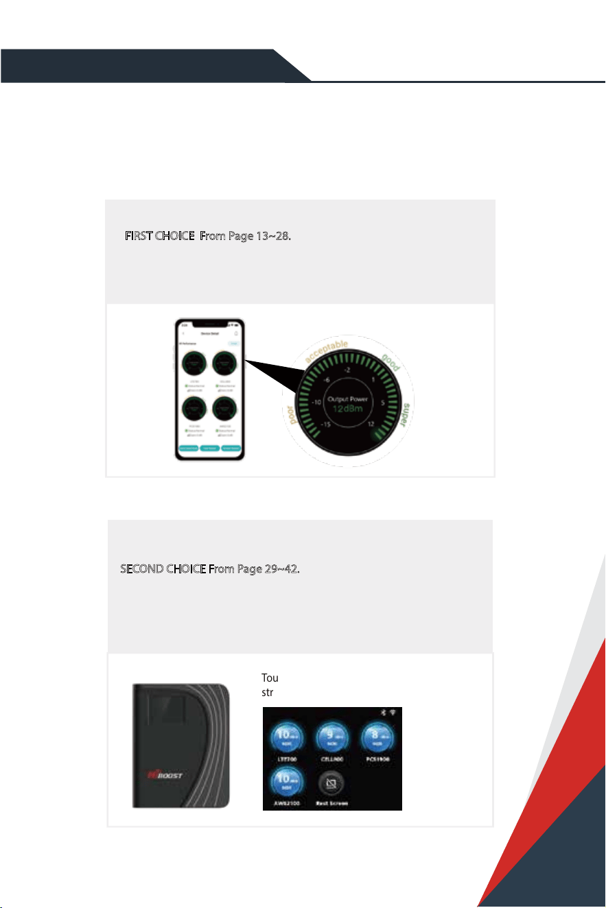
HiBoost 4K/10K Mate Plus/Plus Pro provide 2 options of booster installation,
APP and LCD installation ways are unique methods provided by HiBoost
1. App assisted installation,
FIRST CHOICE From Page 13~28.
It’s more convenient and many work could be done by ONE person,
and the most important is that the obtained signal can be very precise.
2. LCD assisted installation,
SECOND CHOICE From Page 29~42.
It can achieve the same precise eect as App guidance.
But it may need two people and the installation process is a little
cumbersome.
Touchable LCD meter tells how
strong the signal is
Pre-Installation Instructions
The App helps you nd the
best signal outside

05
Then why has HiBoost spent extra big eorts and costs to design APP and LCD signal
meters to help you install?
Out of the various reasons, the most important reason is that we would like you, our valuable client, to get
the maximum output power from the booster system in order to get optimal signal reception for all your
mobile devices.
As it is known and a big thanks, FCC makes signal boosters legal in 2014 so that every body can install
and benet from the signals;
But FCC regulations do limit the gain and output power of all consumer boosters to low values in
order to avoid any interference to the cell towers;
Furthermore FCC stipulates that any improper install should trigger immediately further reduction of
the booster’s already-limited gain and power to protect the towers.
Therefore, you can understand how important you need to nd the perfect outside signal from the
tower and how important to squeeze every last gain and power from the booster, even 1dB more
power is so precious when you suer from no signals.
HiBoost App & LCD signal meters will help you to ne tune the best power and get
as much cover of your spaces.
06
General Working Principle:
※
Please do spend sometime to read it fully, as it is crucial to get full bars for your rooms.
Before we start any of the two ways, please allow us to spend 3 pages to make you
understand how the booster system works for you.
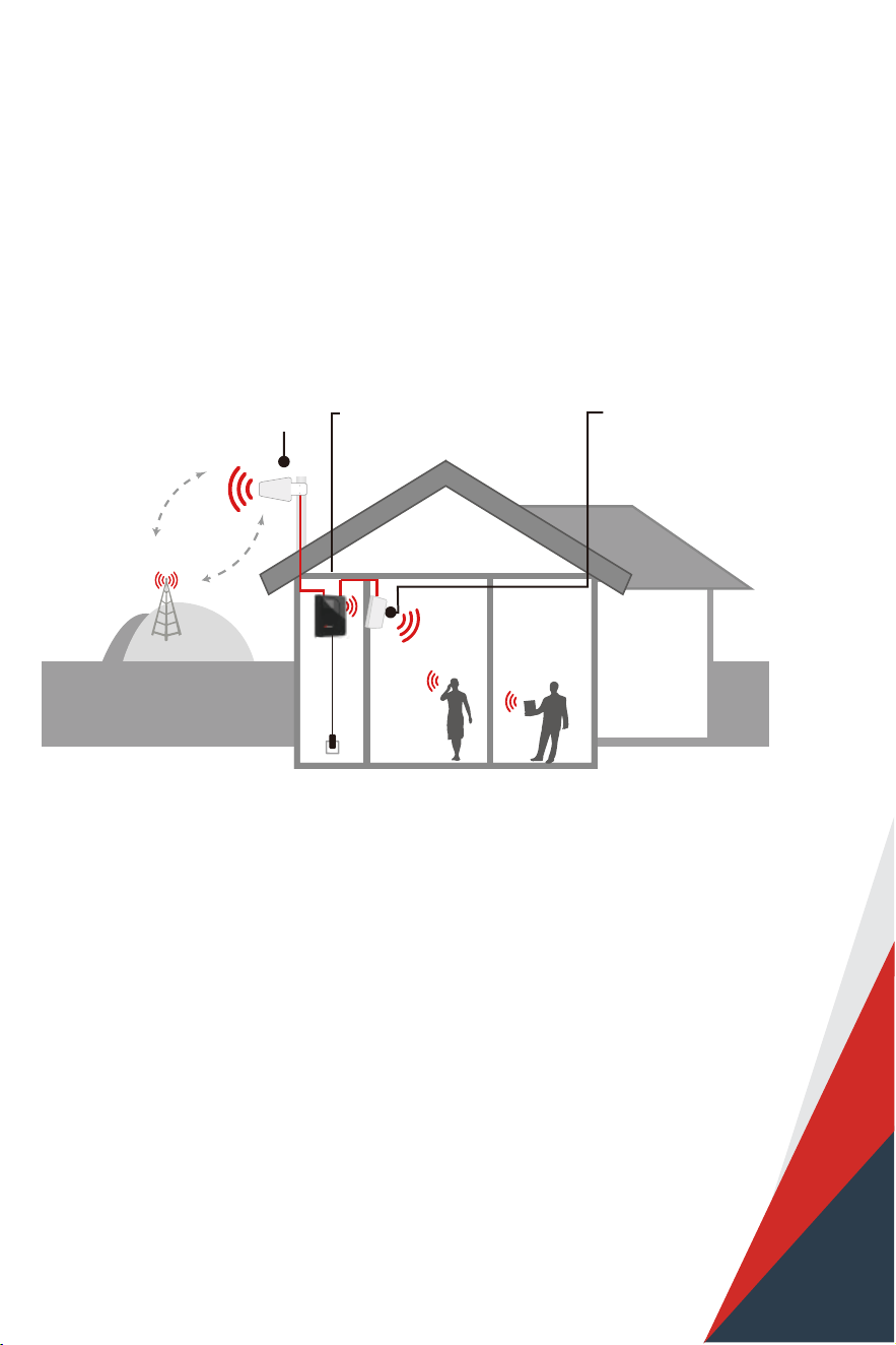
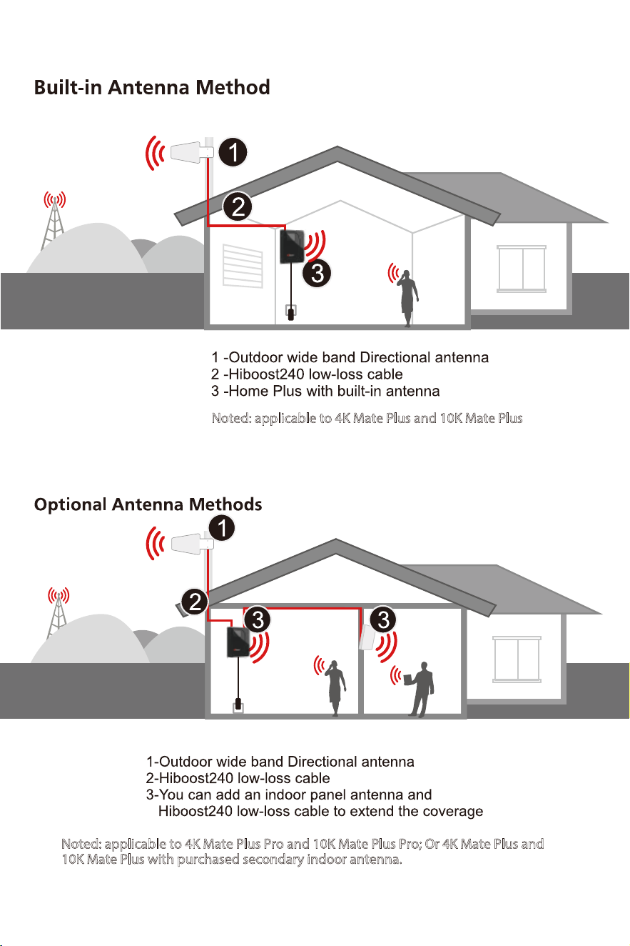
How HiBoost Booster works
1. Outdoor antenna receives
outside signal from the nearby
cell tower and sends it to
HiBoost Booster
2. The booster amplifies the
signal and sends to indoor
antenna(s);
3. Indoor antenna(s) receive
amplified signal and send it
throughout your rooms
Vice versa,booster(plus)/indoor antenna receices cellphone signal and sends to the booster
The booster then amplies the signal and sends it to outdoor antenna
Outdoor antenna sends signal to the cell tower
Then you can make phone calls and internet streaming.
07
Noted: applicable to 4K Mate Plus and 10K Mate Plus
Noted: applicable to 4K Mate Plus Pro and 10K Mate Plus Pro; Or 4K Mate Plus and
10K Mate Plus with purchased secondary indoor antenna.
08
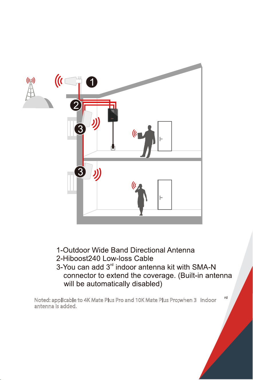
Noted: applicable to 4K Mate Plus Pro and 10K Mate Plus Pro;when 3 indoor
antenna is added.
09
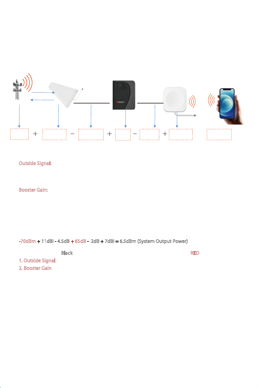
Working Principle in Formula
Outside
Signal
Outdoor
Antenna Gain
Outdoor
Cable Loss
Booster
Gain
Indoor
Cable Loss
Indoor
Antenna Gain
System
Output Power
Out of the Formula:
Outside Signal:
To be received by outdoor antenna from cell tower
Outdoor Antenna Gain: The gain of outdoor antenna
Outdoor Cable Loss: The loss of the outdoor cable
Booster Gain:
The actual working gain of the booster
Indoor Cable Loss: The loss of the indoor cable
Indoor Antenna Gain: The gain of indoor antenna
For example:
-70dBm + 11dBi - 4.5dB + 65dB - 2dB + 7dBi = 6.5dBm (System Output Power)
Since the gures in Black color are xed when you nish the purchase, thus the RED gures of
1. Outside Signal
2. Booster Gain
will play a vital role in reaching the best output power during the install, especially
when we know the FCC limits the booster system values.
So the user guide is focused on:
1. Getting the best outside signal.
2. Keeping the maximum booster gain.
=
10
More notes on how to keep the maximum booster gain
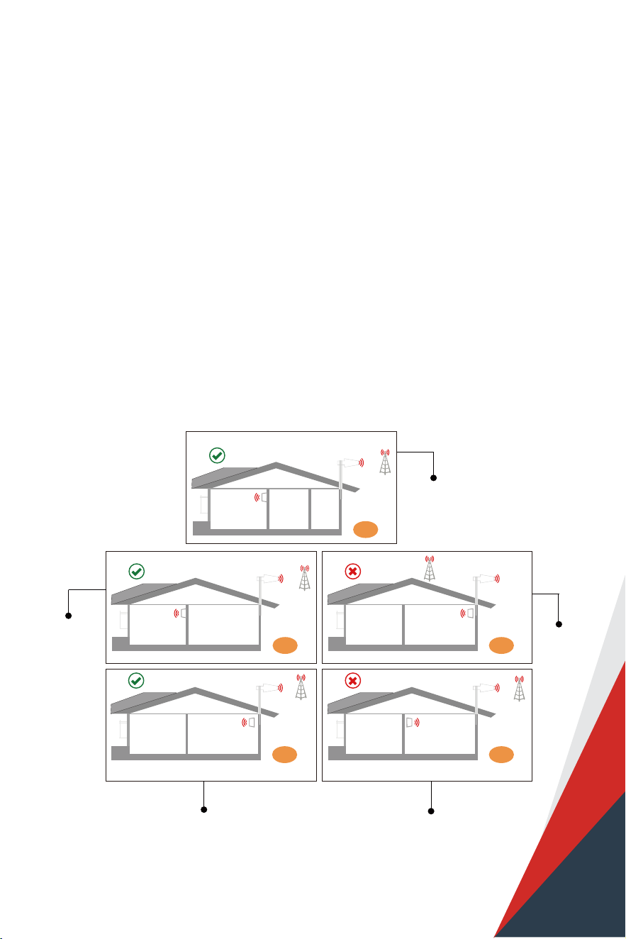
※ Please note: This separation is not an absolute mandate. The idea is to isolate the outdoor
antenna from the two indoor antennas.
1) Increase the distance between the outdoor and indoor antennas, generally the same vertical
distance generates more loss than horizontal, and to follow easily, a Typical Required Distance
Between Outdoor and Indoor Antennas Over 30 feet (10 meters) horizontal distance or 13 feet (4
meters) vertical distance.
2) The outdoor and indoor antennas shall be back to back.
3) Use barriers between the indoor and outdoor antennas.
The loop back from the outdoor antenna to the indoor antennas will reduce the gain, so the principle
to keep the maximum booster gain is to avoid the loop back from the outdoor antenna to the indoor
antennas.
2
54
3
1
1. Point to the tower
2. Antennas back to back
3. Three wall barriers
1. Not pointing
to the tower
1. Point to the tower
2. Antennas back to back
3. Two wall Barriers
1. Point to the tower
2. Antennas back to back
3. No barriers, make sure
vertical distance enough
1. Two antennas facing the same direction
2. Vertical distance might not be enough
Perfect
Super
Acceptable
Bad
Bad
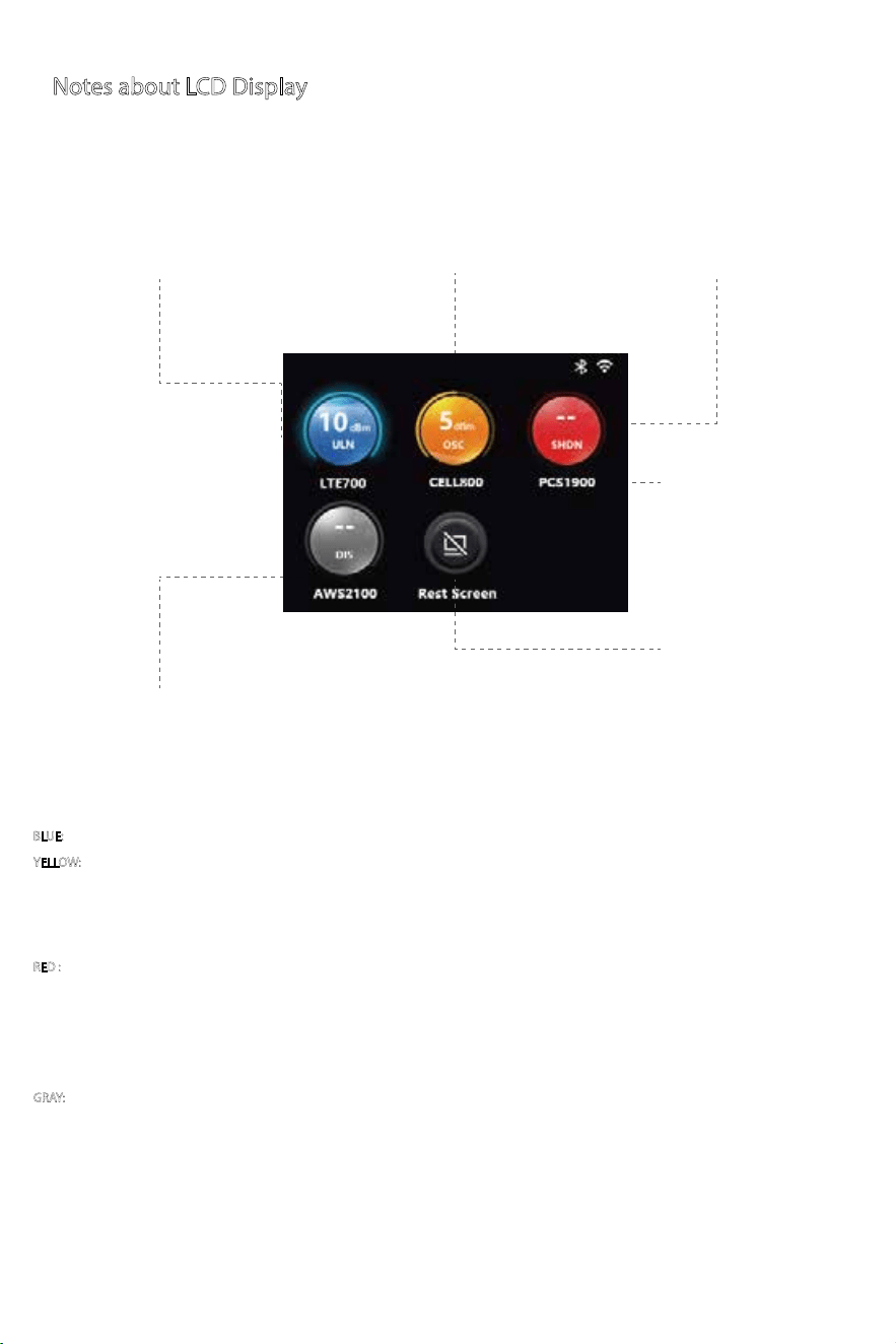
These are instructions that will allow users to install a Barsguar d cell phone
booster using the LCD Display .
Following LCD status indicators and control buttons on the booster .
Notes about LCD Display
DL Output Power Amount: Indicates the amount of DL
output power for this frequency band. 10dbm(4k) or
12dbm(10k) is the best .
DL Output Power Status: Indicates the status
of DL output power for this frequency band.
Details: Click the corresponding
frequency band (the hot area range is the
entire instrument panel + text) to enter
the frequency band parameter details
page;
Reset Screen: Click on the screen to turn
o the screen immediately, and the
touch screen lights up; if there is no
operation within 3 minutes, the screen
turns o, and the screen is turned on
again to display the home page by
default.
Frequency band status: full gain status (normal
status, blue), weak oscillation status (yellow),
oscillation shutdown status (red), and user active
shutdown status (gray).
Band: Shows the working
frequency bands the booster is
operating on.
BLUE: Blue icon with ULN/AOL (Normal/Overload) indicates that a band is working correctly with maximum allowable gain.
YELLOW:
Yellow icon with OSC (Oscillation) indicates band gain reduction because of a slight self-oscillation condition. Due to self-oscillation issue,
please check the antenna system. Reinstall antennas and increase the isolation between outdoor and indoor antennas, and then turn the booster
on to reactivate the band and maximize performance. After the proper isolation is done, the yellow icon will return to blue.
Note: when the icon is yellow, the band still works normally, but the gain is reduced.
RED :
Red icon with SHDN (Shutdown) indicates a band has been shut down because of a strong self-oscillation condition or an over load condition
(You could click the icon to see which condition now is). 1. For the strong self-oscillation condition, please check distance and direction of outdoor
antenna and indoor antenna, increase the isolation of both antennas. After the isolation is enough, the red icon will return to blue upon reboot. 2.
For the over load condition, It’s because of that the input signal is too strong, please adjust outdoor antenna’s direction to reduce the strength of the
input signal, then turn the booster on to reactivate the band. When the gain is reduced enough, the red icon will return to blue upon reboot.
GRAY:
Gray icon with DIS (Disabled) indicates band has been disabled..
11
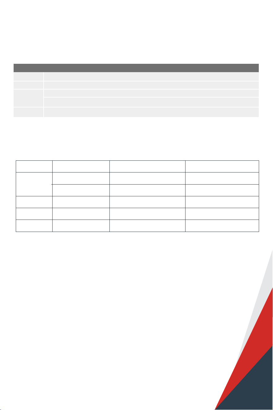
Booster Light Patterns
Bands contained in the Gauges
Gauge Band Uplink Downlink
LTE700
CELL800
PCS1900
AWS2100
4 1710-1755MHz 2110-2155MHz
12/17 698-716MHz 728-746MHz
13 776-787MHz 746-757MHz
5 824-849MHz 869-894MHz
25/2 1850-1915MHz 1930-1995MHz
Please just focus on the gauge that contains the band you are using.
COLOR
INDICATION
Blue
Yellow
Red
Gray
Band works correctly with maximum allowable gain
Band gain reduction because of a slight loopback condition
1. Band has been shut down because of a strong loopback condition
2. Band has been shut down because of an overload condition
Band has been disabled.
12
13
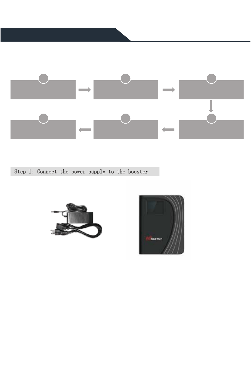
Flow chart of App Assisted Installation
Connect the power supply
to the booster
1 2 3
Connect the booster with
the app
Find the cell tower &
Determine the outdoor
6 5 4
Install the outdoor antenna
Install the booster and
cables
APP Assisted Installation
Step 1: Connect the power supply to the booster
Install the indoor
antenna(s)
Power Supply Signal Booster

14
Step 2: Connect the booster with the app
1) Search “Signal Supervisor” on Google Play/ App Store, or scan the above QR Code to download.
2) Register on the Signal Supervisor APP.
3) Plug in the booster
* The Bluetooth/WiFi antenna is of built-in type,
* There is no need to connect outdoor or indoor antennas at this moment.
4) Click “Add Device” to register the booster into the APP. And we recommend WiFi connection because
the Bluetooth connection can’t go beyond 30ft. Check more steps about the App uses as below.
Download the Signal Supervisor App,
register ID and booster.
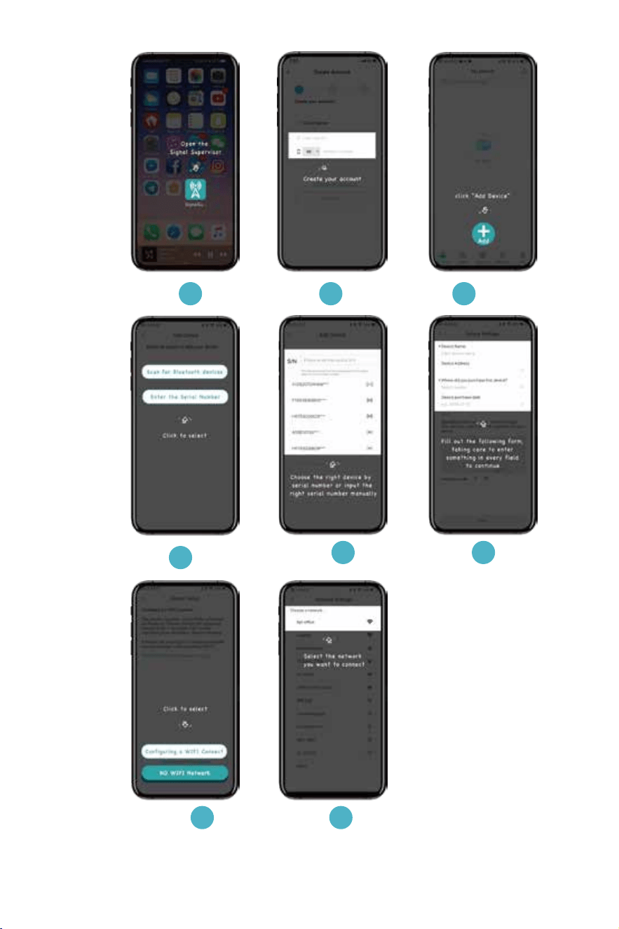
15
1 32
4
6
7 8
5
16
Due to the variety of phone models and the WiFi router types, there is a situation, though
it is rare, where the booster cannot be linked to the Signal Supervisor app successfully.
If such situation is encountered:
* You can alternatively use LCD signal meter to assist your installation.
And Bluetooth/WiFi disconnection won’t inuence the booster working status at all.
* Or please use another cell phone or change a WiFi router if you insist an app assisted installation.
Please contact our tech support if you have diculties in installation, and we will provide the
best solution for you.
Step 3: Find the cell tower & Determine the outdoor antenna’s position
3.1 Find the band you are using
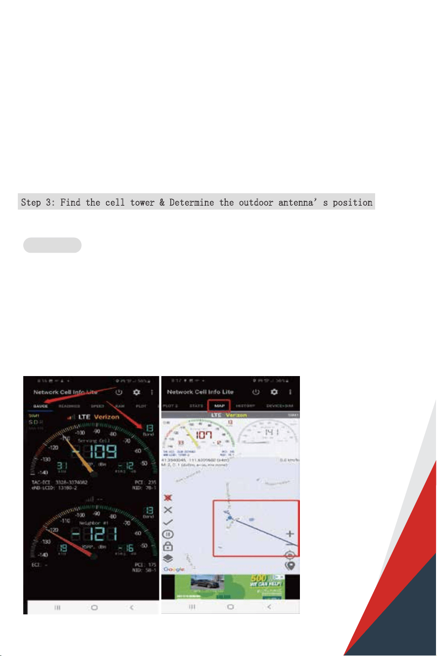
Download NetWork Cell Info Lite in the Google store and open it.
It can be seen from the example picture that the frequency band is band 13.
(According to the form before, you need to pay attention to Gauge LTE700)
Then click MAP. You can see your phone connecting to a tower, and you can try aiming your outdoor antenna
at it. But sometimes this is not accurate. You could also move to Step 3.2 to nd the tower
Note: Please take screenshots at this stage.
For Android
17
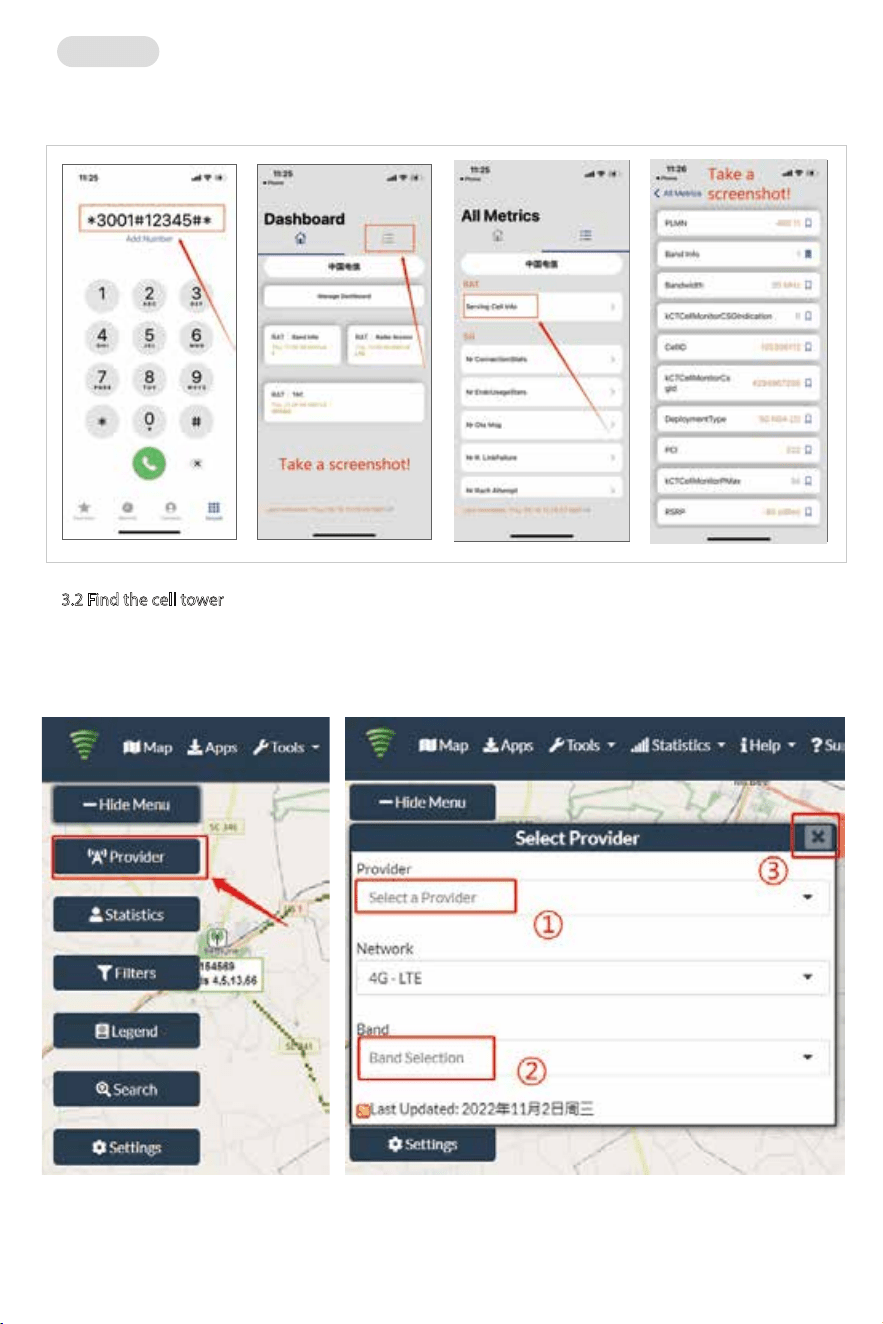
(1)Dial *3001#12345#*
(2)Follow the instructions, take the screenshot as required.
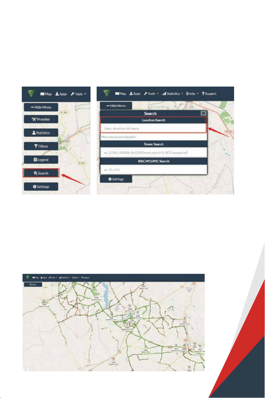
(1) Enter cellmapper.net
(2) Choose your own carrier and band here.
For ios
3.2 Find the cell tower
18
Note: If you need help nding the tower, please contact our tech support
and provide your carrier, band and screenshots taken in the last steps.
(4) After the map jumps to the location, you can scroll the mouse pulley
and zoom it out, then you will see the tower near the location.
It would be better to take a screenshot of this page to guide the following
installing steps. Should you have any questions, please contact our tech support.
(3) Then enter the coordinate of where you are trying to install the signal booster, and press Enter
key.
(In fact when you open Cellmapper, the map on the right will automatically
locate your area if you’ve given the site permission to access your location.
If you found tower sites not even displayed on the map, it might because the app
intercepts the locations for security reasons.)
19
4.1 Connect the booster with outdoor antenna
(1) Put the booster near to the location you would like to install in the future, or a place with power outlet
temporarily.
(2) Plug in the booster and make sure the Signal Supervisor app links with it smoothly.
(3)Connect the 16.4ft cable with the booster’s outdoor port. The booster supports hot plug.
(4) Then connect the window cable with 16.4ft cable and pull the window cable outside and connect it with
49.2ft cable. In case window cable is not needed, connect the 16.4ft cable with 49.2ft cable directly.
(5) Connect the other side of 49.2ft cable with the outdoor antenna.
Notes:
*Please do NOT to connect indoor antenna at this moment as it will inuence the outside
signal nding.
*Please place the booster within 30ft to the possible insatllation location of outdoor antenna
if Bluetooth connection is applied. This is to ensure the App can connect to the booster.
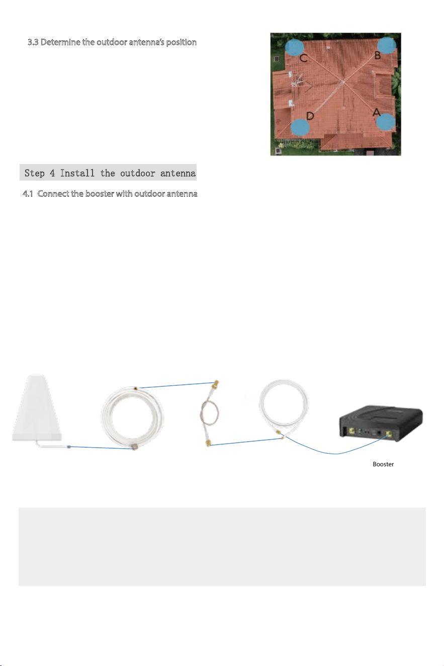
3.3 Determine the outdoor antenna’s position
The outdoor antenna is usually placed at one of the 4 ends
of the roof.
Please choose the position according to the tower’s
location.
Make sure there are no barriers between the antenna and
the tower.
Step 4 Install the outdoor antenna
Booster
Outdoor cable to Booster
16.4ft SMAF-SMAM
Outdoor Antenna
Outdoor Cable
49.2ft NM-SMAM
SMA-Male to SMA-Female
(No drilled hole)
Through-Window Cable
20
4.2 Adjust and x the outdoor antenna
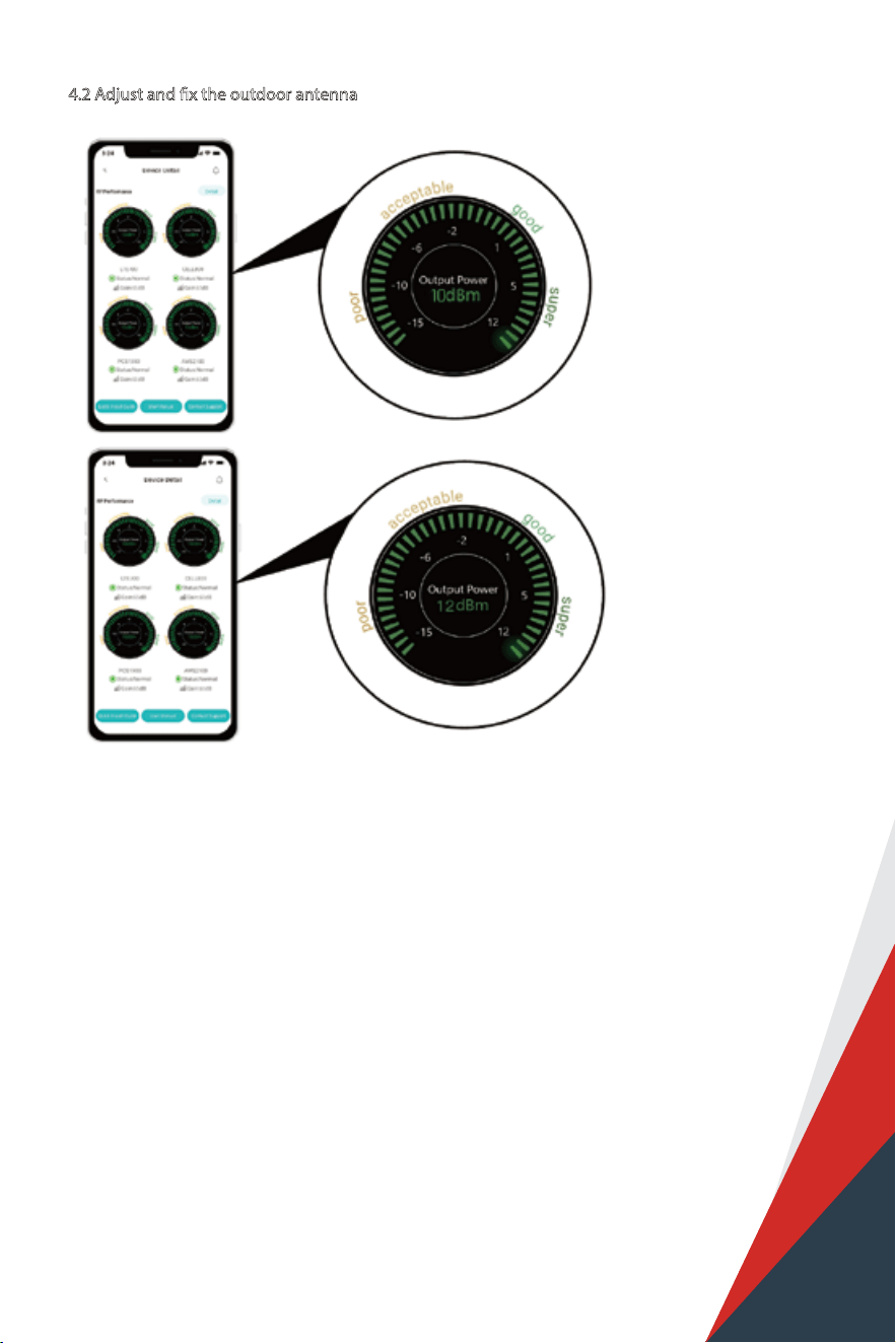
The full output power for 10K Mate Plus and 10K Mate Plus pro is 12dbm.
And the full gain is 68dB.
Have your outdoor antenna pointed to the cell tower you found before and observe the reading
on the app. Adjust the outdoor antenna accordingly.
Target: Try to get the highest possible output power for each band and try to make 2-3 gauges
turn green.
1) You can either look at the signal meter value, full output power is the best
2) Or you can look at the signal description, Super is the best
The full output power for 4K Mate Plus and 4K Mate Plus pro is 10dbm.
And the full gain is 65dB.
21
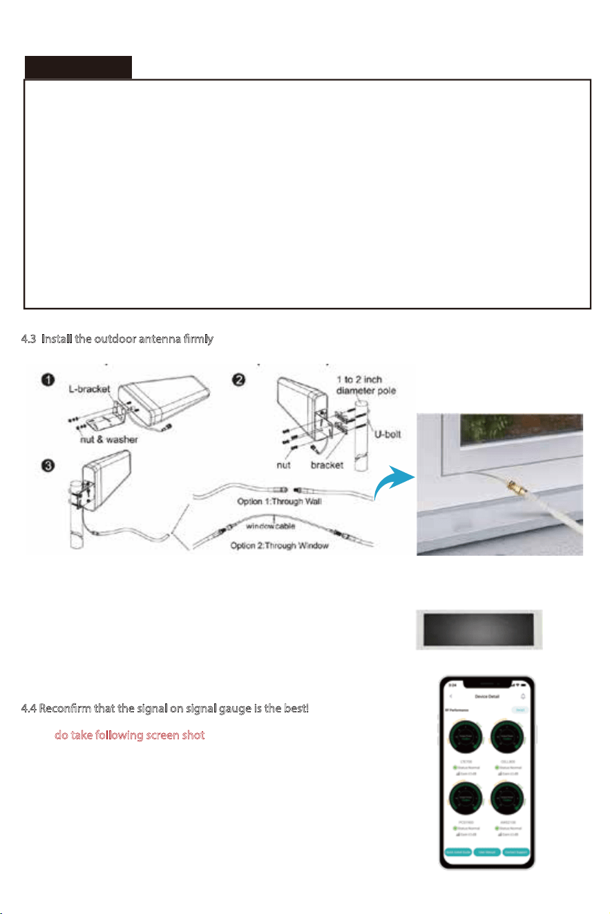
4.3 Install the outdoor antenna rmly
The connector of the cable connection part must be glued with black waterproof tape to prevent
long-term signal drop and reduce signal loss!
Please do take following screen shot for future comparison during indoor
antenna installation.
What you are going to be paying attention to here, is the gain values. If you
have interference between your indoor and outdoor antennas, then the
booster will lower the gain and these values will decrease.
4.4 Reconrm that the signal on signal gauge is the best!
Professional Tips
• Keep in mind that it is normal for the output values may vary dynamically between 1-3 dB
• To optimize the signal for one carrier, point the outdoor antenna towards the closest cell phone tower designated to that
carrier
• To optimize the signal for more than one carrier, point the outdoor antenna between multiple towers
• Make sure to slowly turn the antenna while taking the readings so the booster has time to adjust the reading
• Test and install the antenna at the same height where power outputs and gain values reach the booster‘s maximum
capacity
•
Professional Tips
If you can’t get a good output power, for instance, the value is below POOR level, it is highly likely that the installation
will fail. Please either nd a new place with better signal or drop the installation.
Step 5: Install the indoor antenna(s)
Note: It is better to have two people at this stage. One can go around to nd the best place for indoor
antenna. While the other can walk around to do test all over to make sure every spot is covered with
stable and high quality signal.
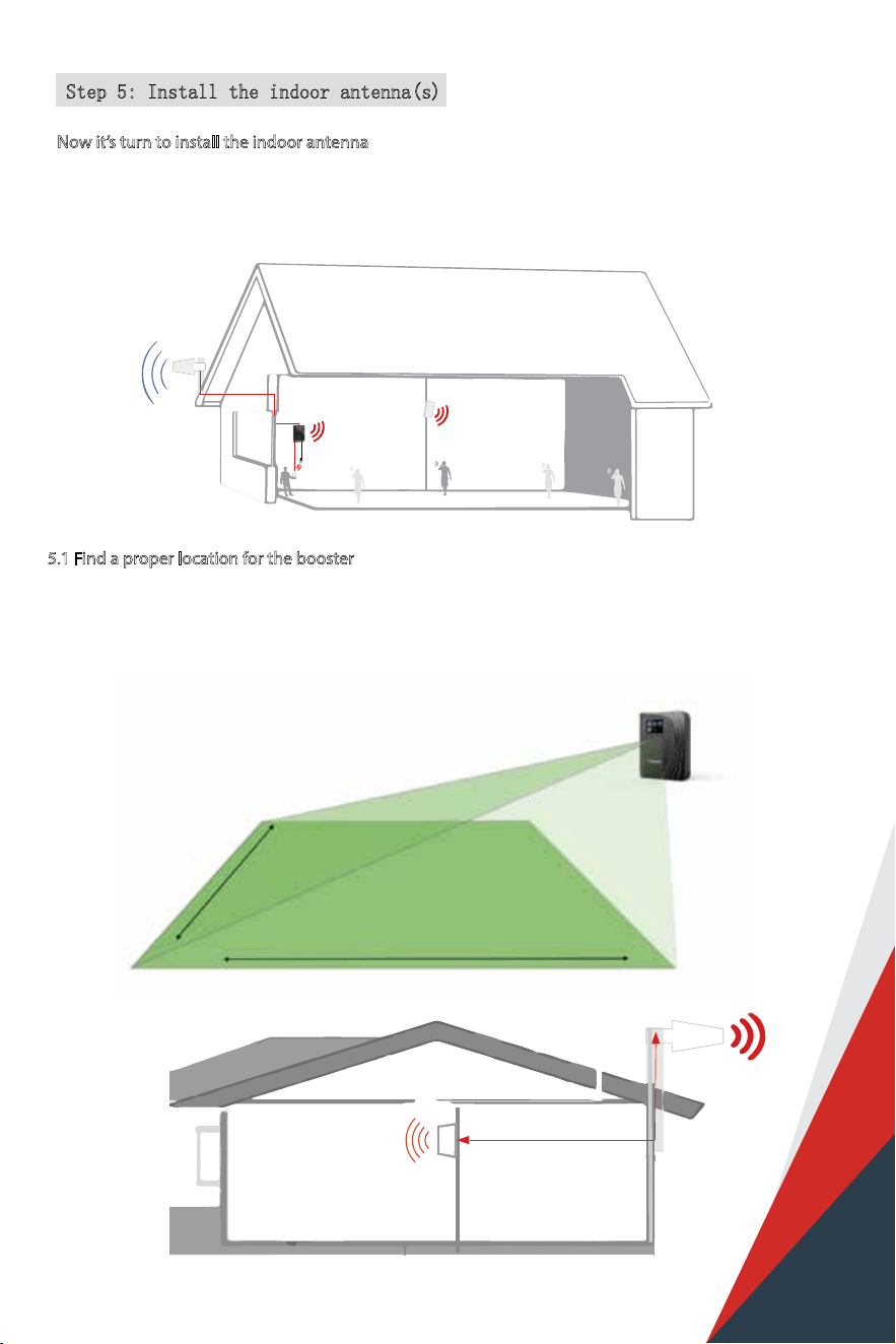
Now it’s turn to install the indoor antenna
5.1 Find a proper location for the booster
1) As 4K/10K Mate Plus and 4K/10K Mate Plus Pro are equiped with a built-in antenna, the booster
should be installed as a panel antenna.The radiation pattern is 80° horizontal and 70°vertical. So try to
make sure your indoor antenna pointed to the area you would like to cover with signal.
30ft horizontal
30ft
30ft
13ft vertical
22
5.2
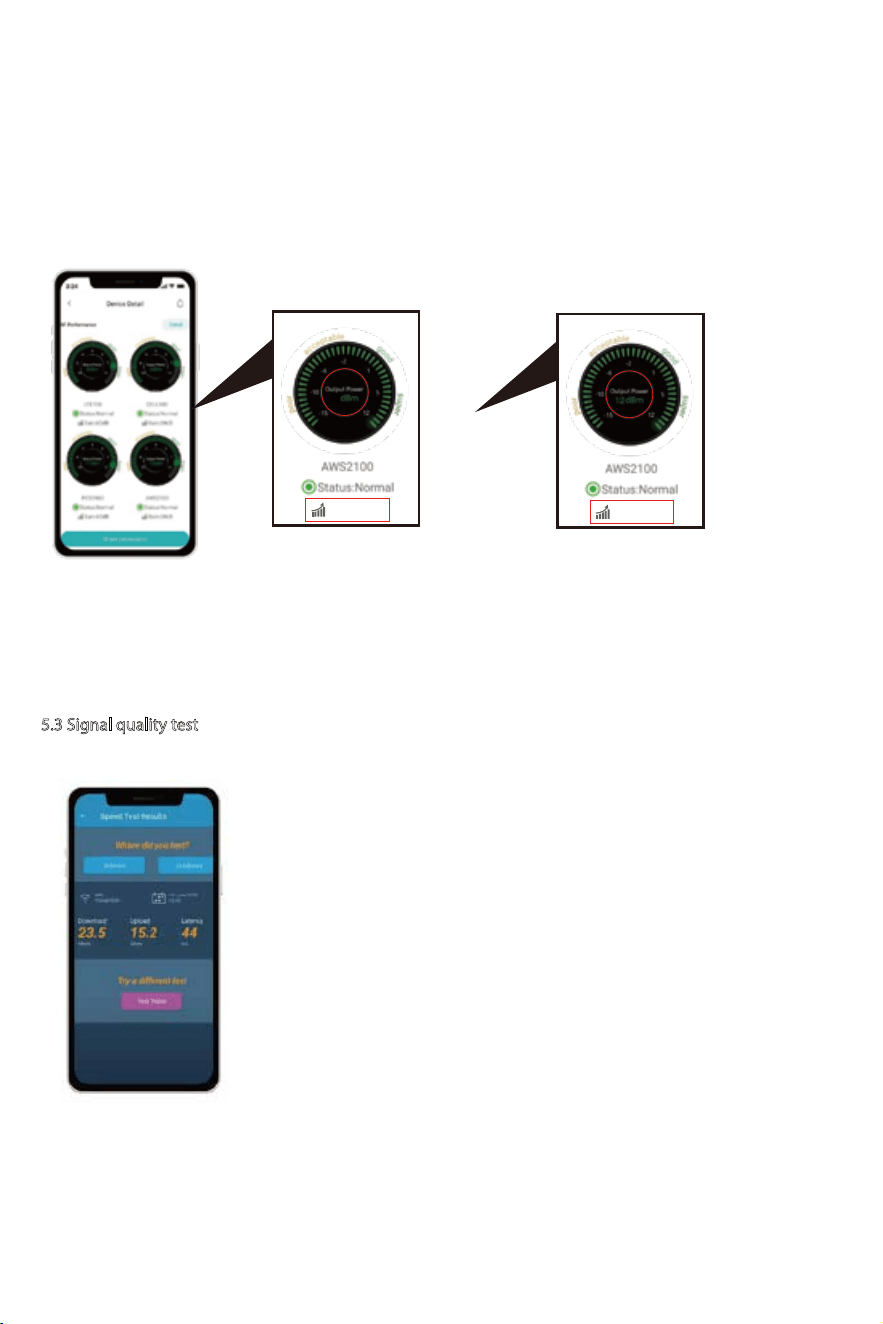
It would be best if you could make the two antennas face opposite directions.
For 4K Mate Plus and 4K Mate Plus Pro, make sure that the gain reaches about 60 dB; For 10K
Mate Plus and 10K Mate Plus Pro, make sure that the gain reaches about 65 dB. If not, please
adjust the direction of the indoor antenna/increase the vertical and horizontal distance between
the two antennas/add some barriers.
5.3 Signal quality test
You could do the following:
(1)First make sure the signal gauge value is unchanged from that during
the outdoor antenna installation.
(2)Do speed tests with the booster on and o, and make a comparison.
(3)Check if the number of signal bars increases.
(4)Make a phone call or send messages and check if the voice and
streaming are better.
Adjust the indoor antenna
Gain: 65dB
Gain: 68dB
23
10
Panel antenna
30ft
24
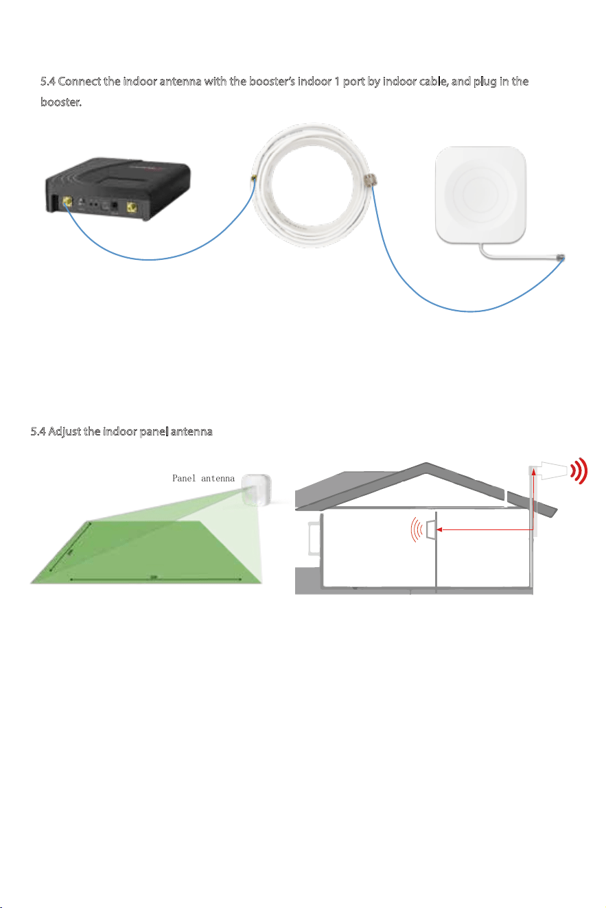
5.4 Connect the indoor antenna with the booster’s indoor 1 port by indoor cable, and plug in the
booster.
Indoor Cable
30ft SMAM-NM
Indoor Antenna NFBooster
Notes:4K/10K Mate Plus has a built-in antenna so you needn't to install indoor panel antenna(s),
4K/10K Mate Plus Pro is the same situation but if you need more rooms to be covered, follow
this step. (Each HiBoost Plus/Pro series has two additional indoor antennas' port, but it should
be noted that if indoor2 port is occupied, the built-in antenna will be disabled)
Please skip to Step6 if you use 4k/10k Mate Plus.
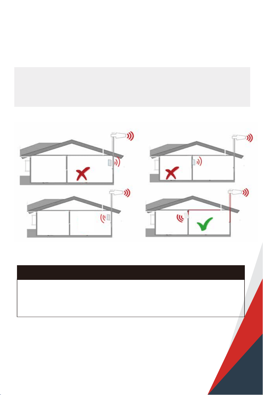
5.4 Adjust the indoor panel antenna
Notes:
It would be best if you could make the outdoor antenna and the two indoor antennas face opposite
directions.
For 4K Mate Plus Pro, please make sure the gain reaches about 60dB. If not, please adjust the
direction of the indoor antenna/increase the vertical and horizontal distance between the two
antennas/add some barriers.
For 10K Mate Plus Pro, please make sure the gain reaches about 65dB. If not, please adjust the
direction of the indoor antenna/increase the vertical and horizontal distance between the two
antennas/add some barriers.
(1)
(2)
(3)
Have your indoor antenna pointed to the area you would like to cover with signal.
30ft horizontal
13ft vertical
25
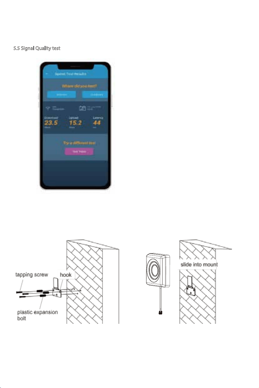
1. Increase the distance between the outdoor and indoor antennas
2. The outdoor and indoor antennas shall face opposite direstions
3. Utilize barriers between the indoor and outdoor antennas
Again the tips to avoid the loopback
Two requests of indoor antenna installation
A. Radiation shall be good enough to cover whole space
B. Loopback shall be avoided
Might be ok
26
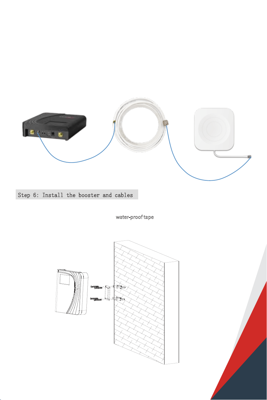
5.5 Signal Quality test
If the test is good, then congratulations, the indoor antenna position has been successfully found. Please install
the indoor panel antenna.
(1)Do speed tests with the booster on and o,
and make a comparison.
(2)Check if the number of signal bars increases.
(3)Make a phone call or send messages and
check if the voice and streaming are better.
You could do the following:
27
If you’d like to cover more rooms, a second indoor panel antenna can be used. Use the 30ft NM-SMAM
cable inside the package to connect indoor 2 port, and then repeat steps of 1st indoor antenna
installation.
Step 6: Install the booster and cables
Mount the signa l booster in a dry and cool area, and it shall be easily accessible for maintenance.
And run the cables neatly, please do use the water-proof tape
to protect all outside
connections from the weather.
Indoor Cable
30ft SMAM-NM
Indoor Antenna NFBooster
Note:
(1) The built-in antenna will be disabled when the indoor2 port is occupied.
(2) The connector of indoor2 port is SMA-Female, please make sure you buy the right cable.
28
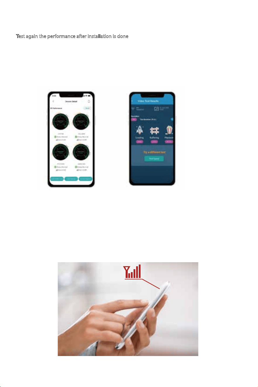
Test again the performance after installation is done
a. First make sure the Signal gauge value is unchanged from that during the outdoor antenna installation.
b. Test with a third-party app, make sure calls and network data iare smooth in most indoor signal coverage
areas.
Now everything is completed and you can enjoy the mobile services.
If the result is not satisfactory or you want better signal, you may repeat the whole or part of the
process to improve.
Should you have any queries during the installation, please kindly contact us via Signal Supervisor App
online support.
29
Connect the power supply
to the booster
1 2
Flow chart of LCD Assisted Install
Find the cell tower &
Determine the outdoor
antenna’s position
3
Install the outdoor antenna
4
Install the indoor antenna
5
Install the booster and
cables
LCD Assisted Installation
Step 1:
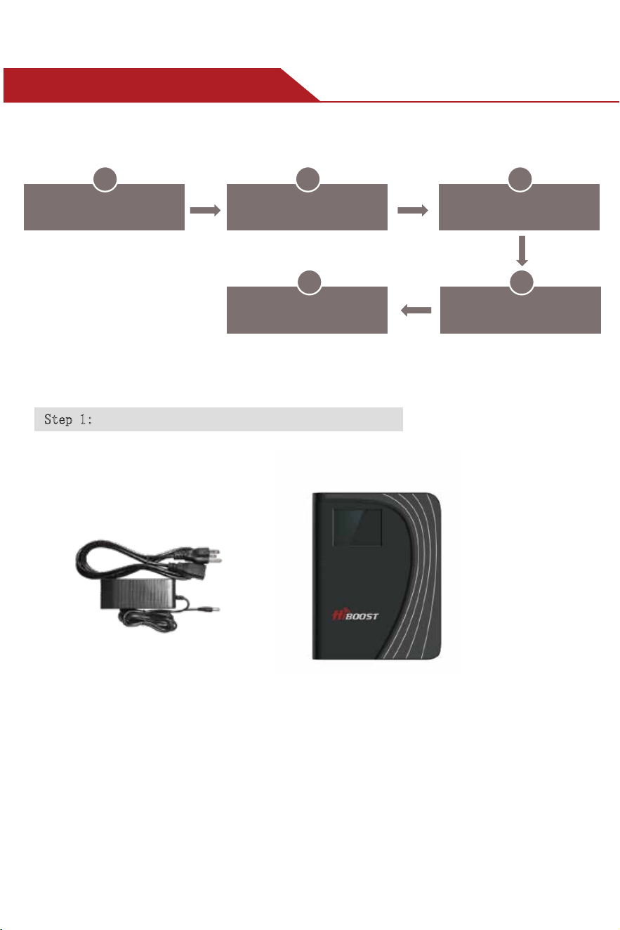
Connect the Power Supply to the Booster
BoosterPower Supply
30
Due to the variety of phone models and the WiFi router types, there is a situation, though
it is rare, where the booster cannot be linked to the Signal Supervisor app successfully.
If such situation is encountered:
* You can alternatively use LCD signal meter to assist your installation.
And Bluetooth/WiFi disconnection won’t inuence the booster working status at all.
* Or please use another cell phone or change a WiFi router if you insist an app assisted installation.
Please contact our tech support if you have diculties in installation, and we will provide the
best solution for you.
Step 2: Find the cell tower & Determine the outdoor antenna’s position
2.1 Find the band you are using
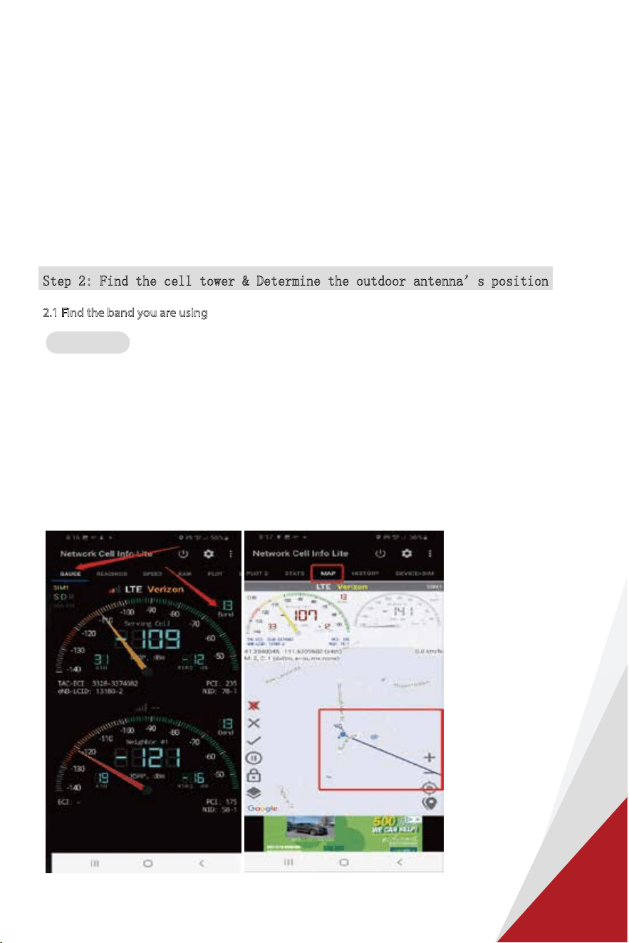
Download NetWork Cell Info Lite in the Google store and open it.
It can be seen from the example picture that the frequency band is band 13.
(According to the form before, you need to pay attention to Gauge LTE700)
Then click MAP. You can see your phone connecting to a tower, and you can try aiming your outdoor antenna
at it. But sometimes this is not accurate. You could also move to Step 3.2 to nd the tower
Note: Please take screenshots at this stage.
For Android
31
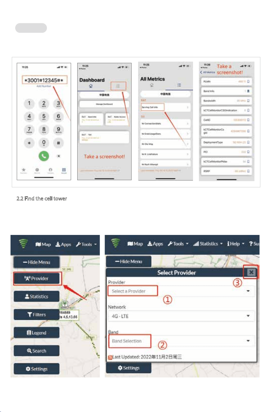
(1)Dial *3001#12345#*
(2)Follow the instructions, take the screenshot as required.
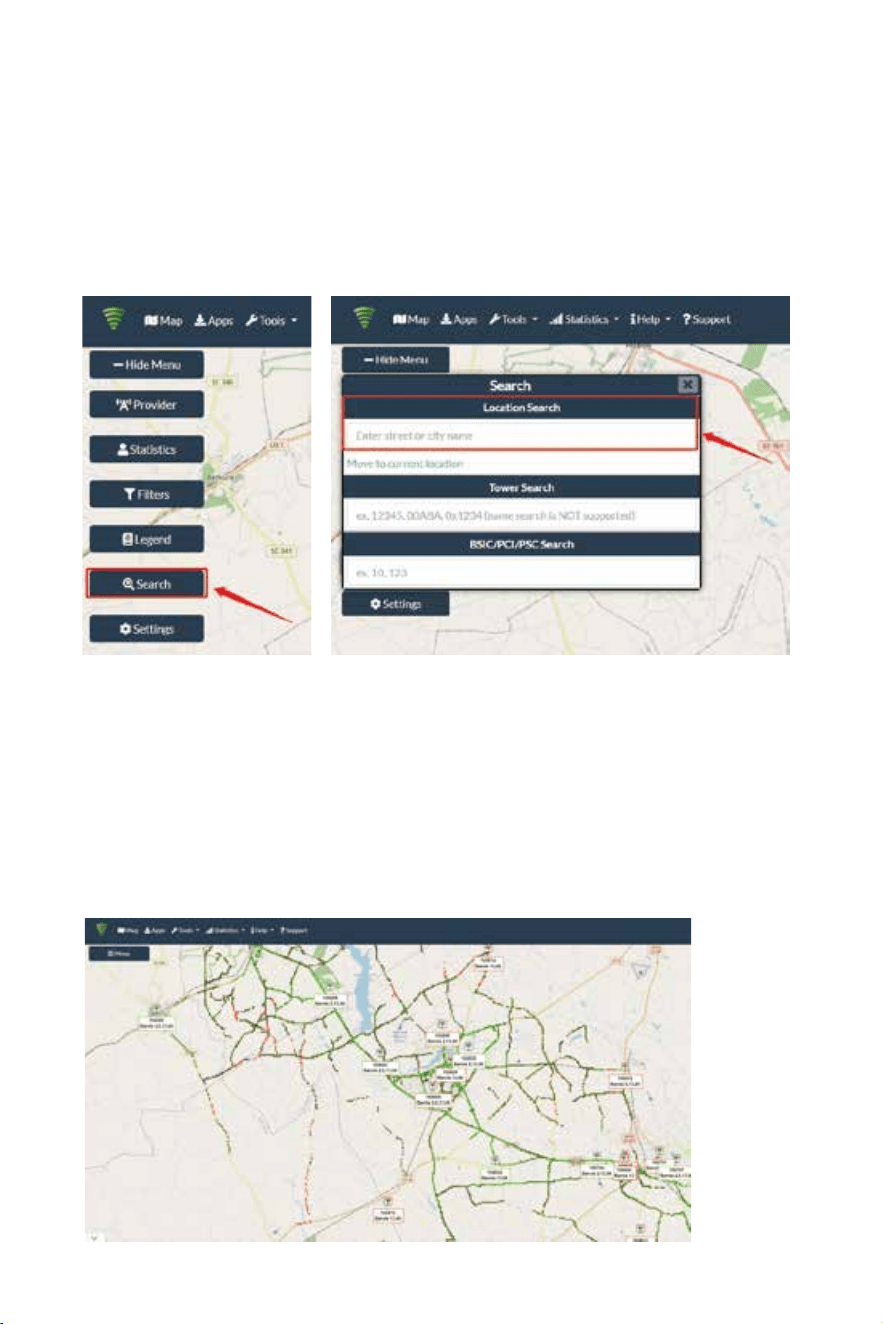
(1) Enter cellmapper.net
(2) Choose your own carrier and band here.
For ios
2.2 Find the cell tower
32
Note: If you need help nding the tower, please contact our tech support
and provide your carrier, band and screenshots taken in the last steps.
(4) After the map jumps to the location, you can scroll the mouse pulley
and zoom it out, then you will see the tower near the location.
It would be better to take a screenshot of this page to guide the following
installing steps. Should you have any questions, please contact our tech support.
(3) Then enter the coordinate of where you are trying to install the signal booster, and press Enter
key.
(In fact when you open Cellmapper, the map on the right will automatically
locate your area if you’ve given the site permission to access your location.
If you found tower sites not even displayed on the map, it might because the app
intercepts the locations for security reasons.)
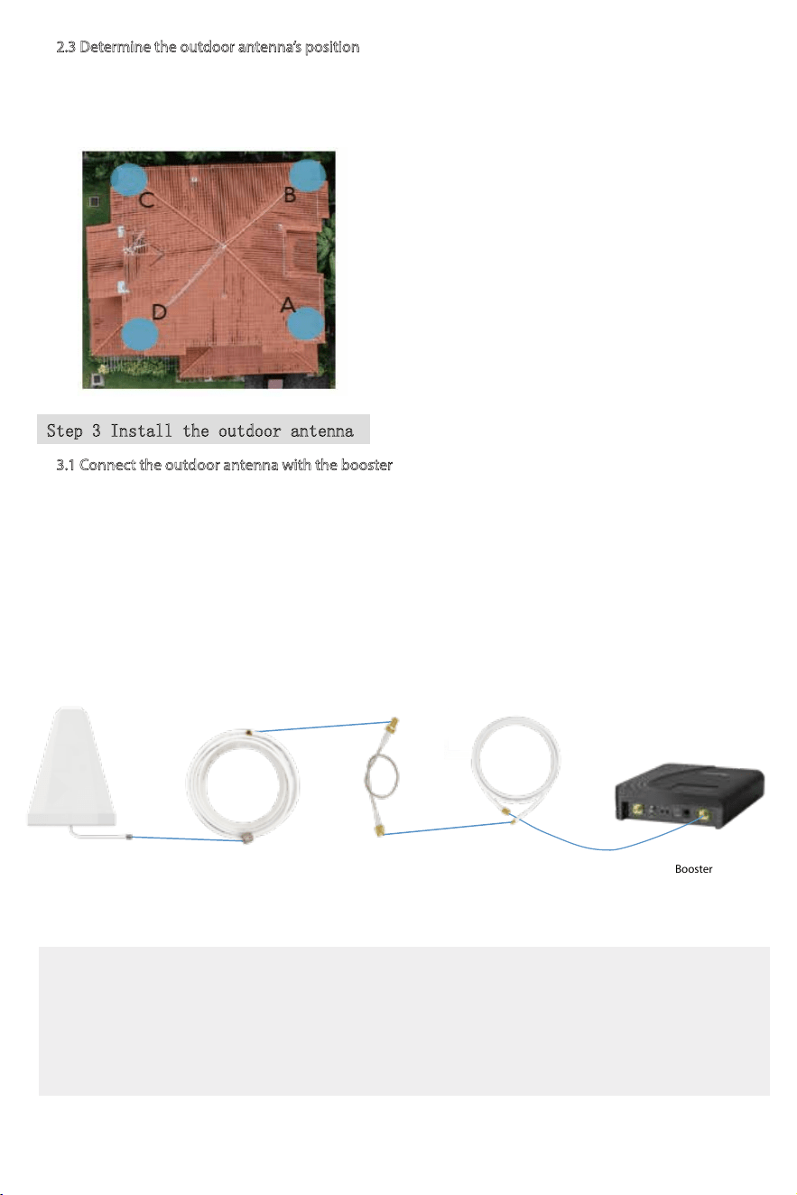
2.3 Determine the outdoor antenna’s position
The outdoor antenna is usually placed at one of the 4 ends of the roof.
Please choose the position according to the tower’s location.
Make sure there are no barriers between the antenna and the tower.
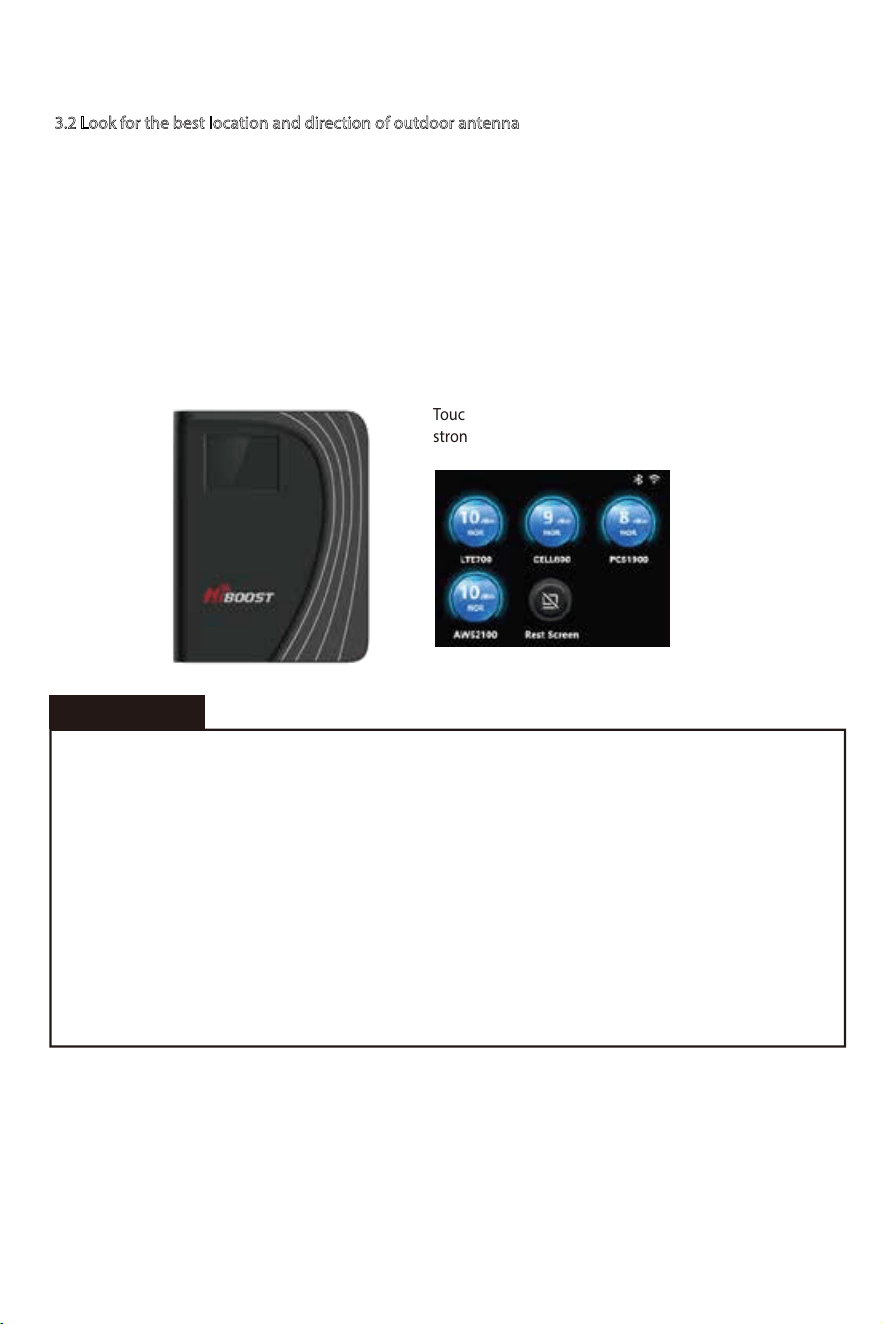
3.1 Connect the outdoor antenna with the booster
Notes:
*Please do NOT to connect indoor antenna at this moment as it will inuence the outside
signal nding.
*Please place the booster within 30ft to the possible insatllation location of outdoor antenna
if Bluetooth connection is applied. This is to ensure the App can connect to the booster.
Step 3 Install the outdoor antenna
(1) Put the booster near to the location you would like to install in the future, or a place with power outlet
temporarily.
(2) Power on the booster and make sure the signal supervisor app links with it smoothly.
(3) Connect the 16.4ft cable with the booster's outdoor port. The booster supports hot plug.
(4) Then connect the window cable with 16.4ft cable and pull the window cable outside and connect it
with 49.2t cable. In case window cable is not needed, connect the 16.4ft cable with 49.2ft cable directly.
(5) Connect the other side of 49.2ft cable with the outdoor antenna.
33
Booster
Outdoor cable to Booster
16.4ft SMAF-SMAM
Outdoor Antenna
Outdoor Cable
49.2ft NM-SMAM
SMA-Male to SMA-Female
(No drilled hole)
Through-Window Cable
34
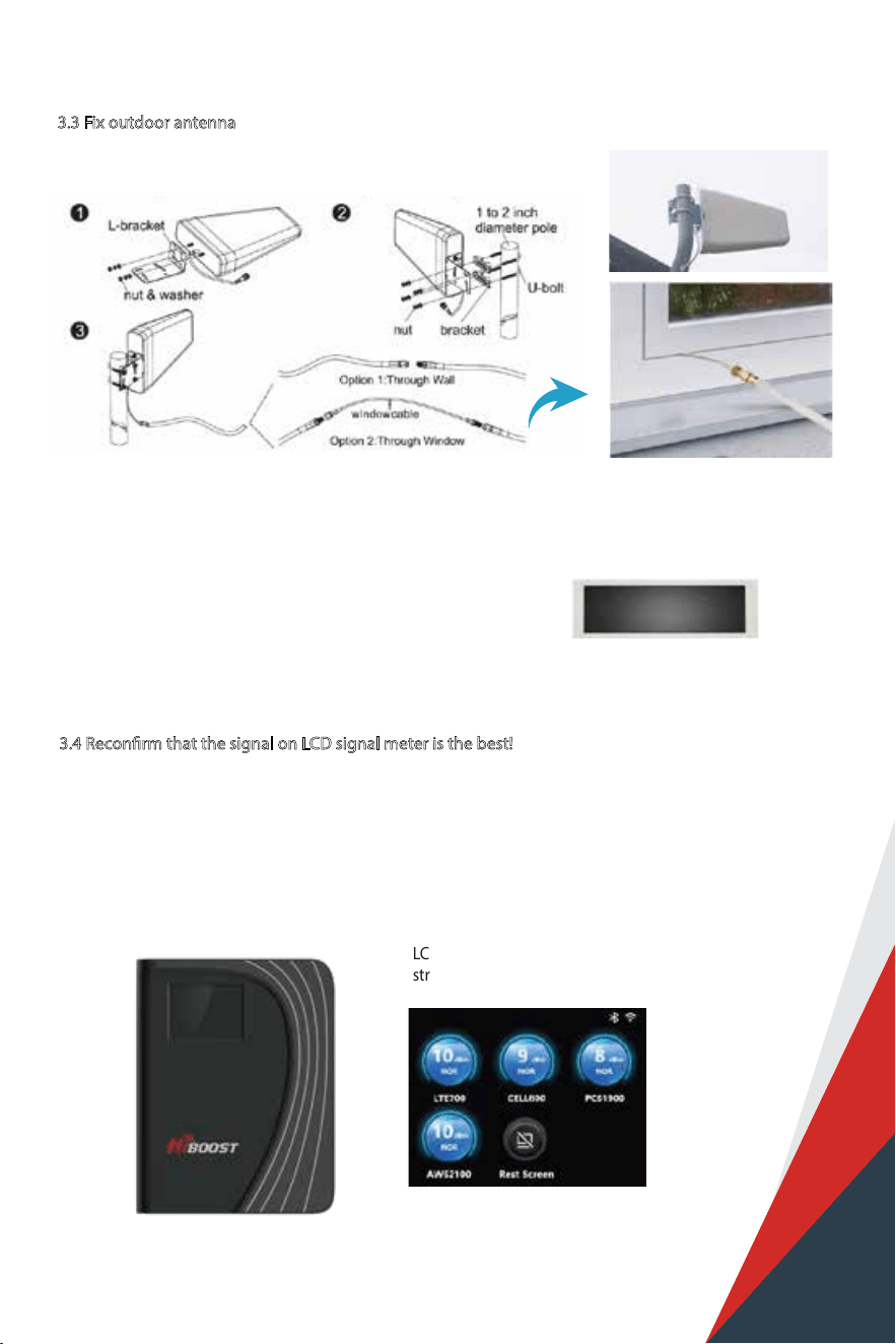
3.2 Look for the best location and direction of outdoor antenna
Now pick up the outdoor antenna and point to above cell tower and adjust its position precisely, ask
your partner to watch the LCD signal gauge to get a strongest possible output signal.
Ask your partner to look at the signal meter value, 10dbm(4k) or 12dbm(10k) is the best.
Notes: The output power level in the signal meter is the level for each of the two indoor antennas.
Fix the outdoor antenna direction when you get the best output power
• Keep in mind that it is normal for the output values may vary dynamically between 1-3 dB
• To optimize the signal for one carrier, point the outdoor antenna towards the closest cell phone tower
designated to that carrier
• To optimize the signal for more than one carrier, point the outdoor antenna between multiple towers
• Make sure to slowly turn the antenna while taking the readings so the booster has time to adjust the
reading
• Test and install the antenna at the same height where power outputs and gain values reach the booster’s
maximum capacity
Professional Tips
Touchable LCD meter tells how
strong the signal is
35
3.3 Fix outdoor antenna
Now install the outdoor antenna rmly
The connector of the cable connection part is glued with black waterproof tape to prevent
long-term signal drop and reduce signal loss!
3.4 Reconrm that the signal on LCD signal meter is the best!
And take photo of LCD signal meter for future comparison during indoor antenna install.
What you are going to be paying attention to here, is the gain values. If you have interference between
your indoor and outdoor antennas, then the booster will lower the gain and these values will decrease.
LCD touchable meter tells how
strong the signal is
36
30ft
30ft
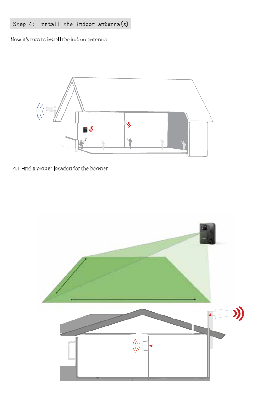
Step 4: Install the indoor antenna(s)
Note: It is better to have two people at this stage. One can go around to nd the best place for indoor
antenna. While the other can walk around to do test all over to make sure every spot is covered with
stable and high quality signal.
Now it’s turn to install the indoor antenna
4.1 Find a proper location for the booster
1) As 4K/10K Mate Plus and 4K/10K Mate Plus Pro are equiped with a built-in antenna, the booster should be
installed as a panel antenna.The radiation pattern is 80° horizontal and 70°vertical. So try to make sure your
indoor antenna pointed to the area you would like to cover with signal.
30ft horizontal
13ft vertical
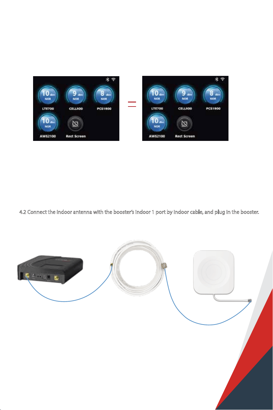
2) After nding the location, hold it there, and ask the other person to compare the gain and power on LCD
signal meter, they shall keep the same or very nearby with the photo taken during outdoor antenna install. This
is to avoid the loop back between outdoor and indoor antennas, please move the indoor antenna till you get
unchanged or slightly changed gain and power. This step is quite crucial for the booster’s best performance.
4.2 Connect the indoor antenna with the booster’s indoor 1 port by indoor cable, and plug in the booster.
Indoor Cable
30ft SMAM-NM
Indoor Antenna NFBooster
Notes:4K/10K Mate Plus has a built-in antenna so you needn't to install indoor panel antenna(s),
4K/10K Mate Plus Pro is the same situation but if you need more rooms to be covered, follow
this step. (Each HiBoost Plus/Pro series has two additional indoor antennas' port, but it should
be noted that if all of them are connected, the built-in antenna will disable)
37
Please skip to Step5 if you use 4k/10k Mate Plus.
38
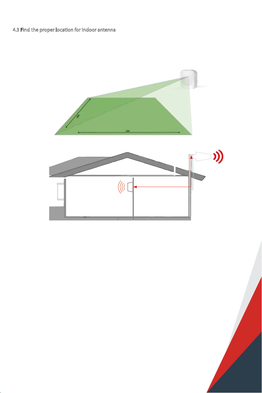
4.3 Find the proper location for indoor antenna
1) The radiation pattern is 80° horizontal and 70°vertical. So try to make sure your indoor antenna pointed to the
area you would like to cover with signal.
30ft horizontal
13ft vertical
Panel antenna
39
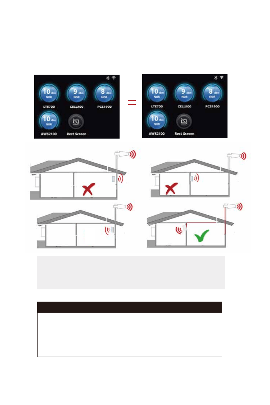
1. Increase the distance between the outdoor and indoor antennas
2. The outdoor and indoor antennas shall be back to back
3. Utilize barriers between the indoor and outdoor antennas
Again the tips to avoid the loop back
2) After nding the location, hold it there, and ask the other person to compare the gain and power on LCD
signal meter, they shall keep the same or very nearby with the photo taken during outdoor antenna install. This
is to avoid the loop back between outdoor and indoor antennas, please move the indoor antenna till you get
unchanged or slightly changed gain and power. This step is quite crucial for the booster’s best performance.
Two requests of indoor antenna install
A. Radiation shall be good enough to cover whole space
B. Loop back shall be avoided
Might be ok
40
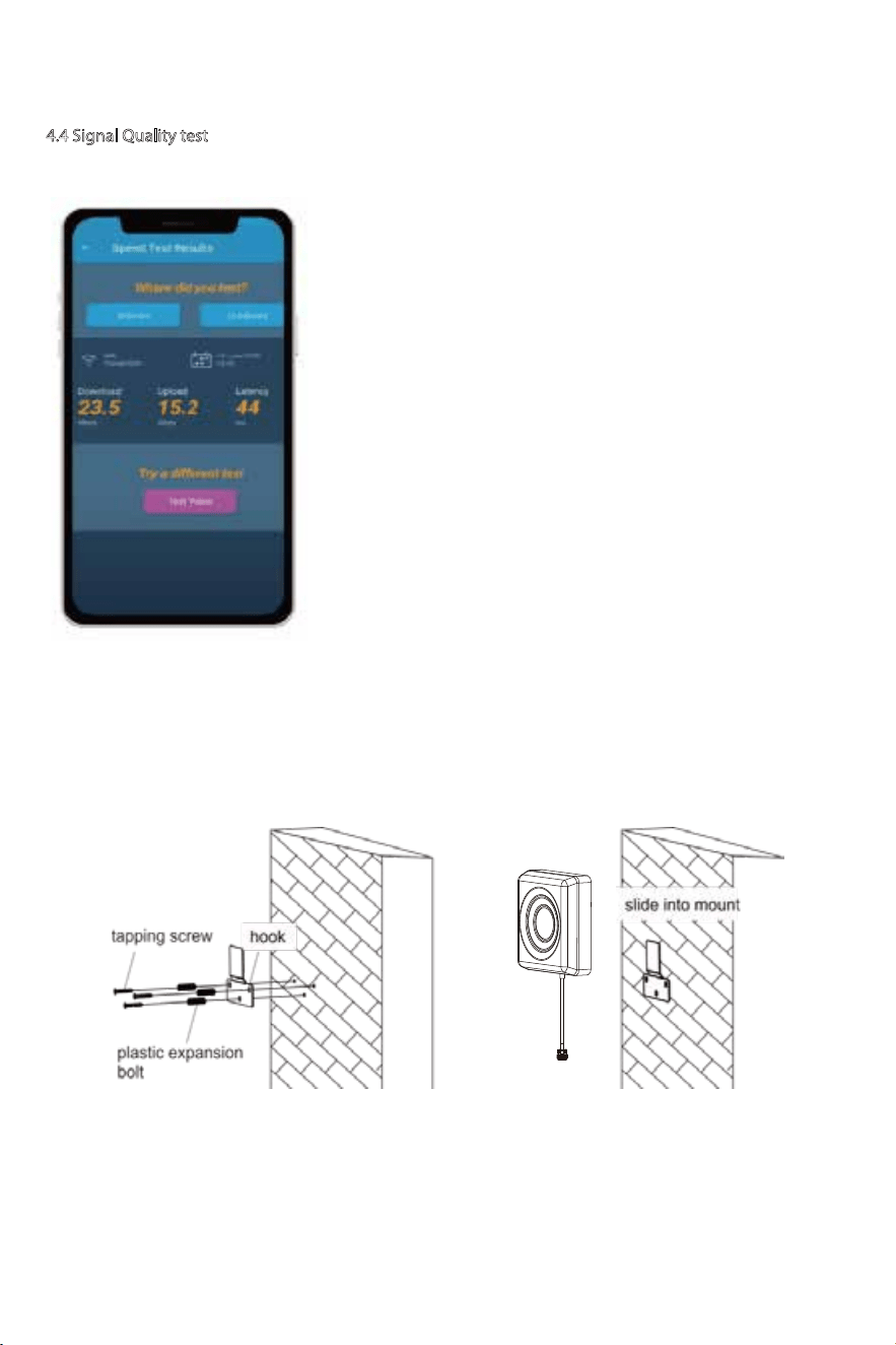
4.4 Signal Quality test
If the test is good, then congratulations, the indoor antenna position has been successfully found. Please install
the 1st indoor antenna.
You could do the following:
(1)First make sure the signal gauge value is unchanged from that during
the outdoor antenna installation.
(2)Do speed tests with the booster on and o, and make a comparison.
(3)Check if the number of signal bars increases.
(4)Make a phone call or send messages and check if the voice and
streaming are better.
41
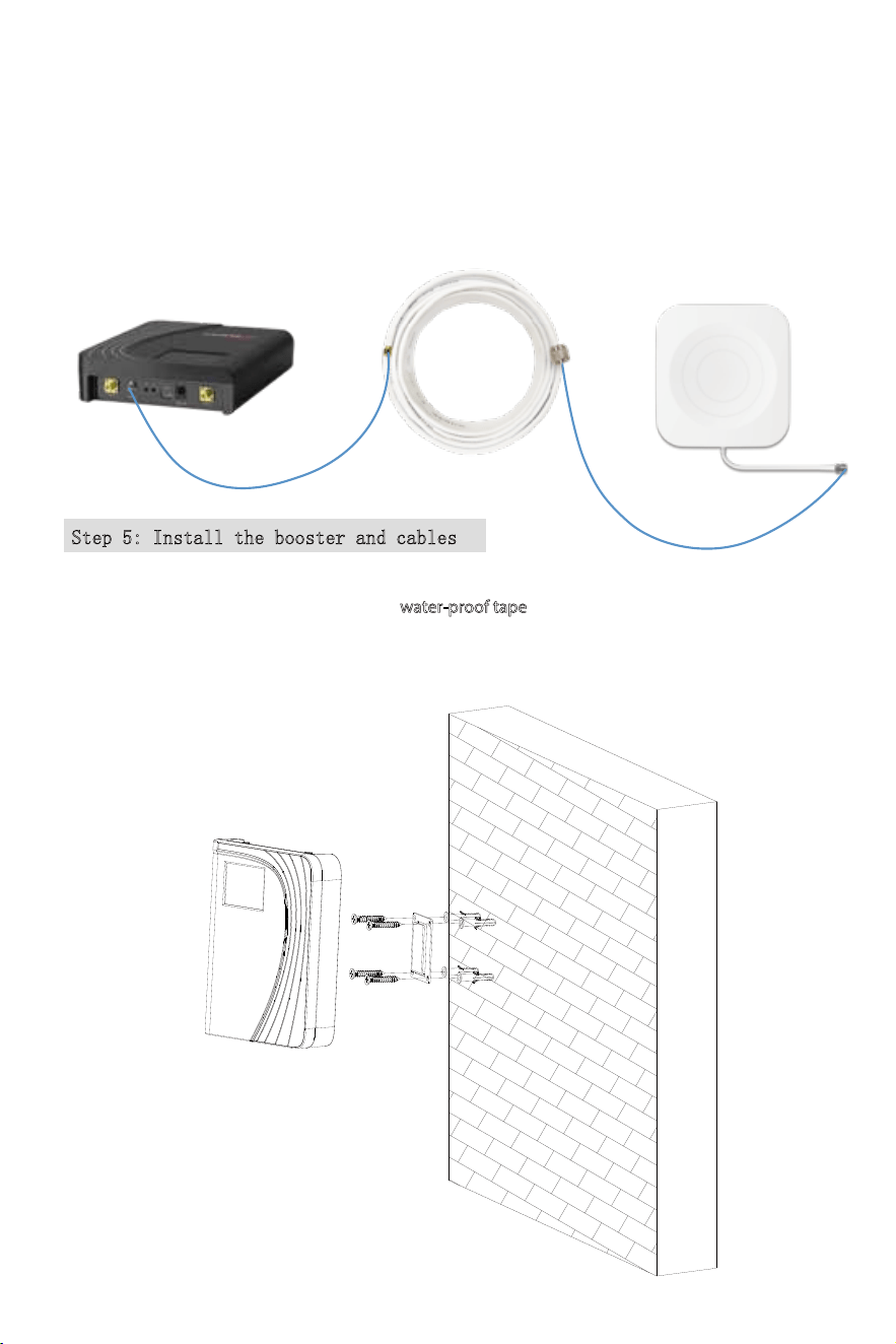
Step 5: Install the booster and cables
Mount the signal booster in a dry and cool area, and it shall be easily accessible for maintenance.
And run the cables neatly, please do use the water-proof tape
to protect all outside
connections from the weather.
If you’d like to cover more rooms, a second indoor panel antenna can be used. Use the 30ft NM-SMAM
cable inside the package to connect indoor 2 port, and then repeat steps of 1st indoor antenna
installation.
Indoor Cable
30ft SMAM-NM
Indoor Antenna NFBooster
Note:
(1) The built-in antenna will be disabled when the indoor2 port is occupied.
(2) The connector of indoor2 port is SMA-Female, please make sure you buy the right cable.
42
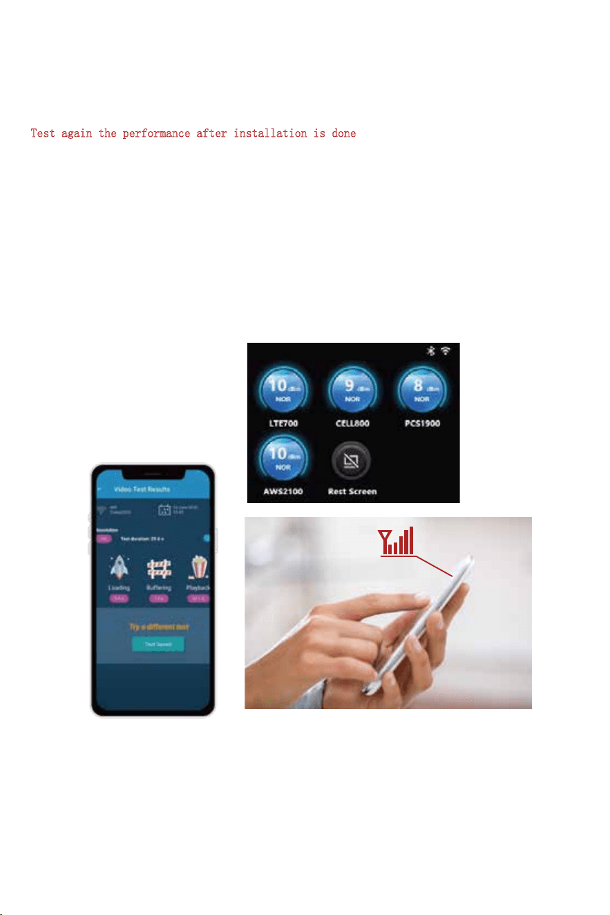
Test again the performance after installation is done
a. First make sure the Signal gauge value is unchanged from that during the outdoor antenna installation.
b. Test by a third-party app, calls and network data are smooth in most indoor signal coverage areas.
Now everything is completed and please start to enjoy the mobile services.
If the result is not satisfactory or you want to be better, you may repeat the whole or part of the process
to improve.
Should you have any queries during the installation, please kindly contact us via Signal Supervisor App
online support.
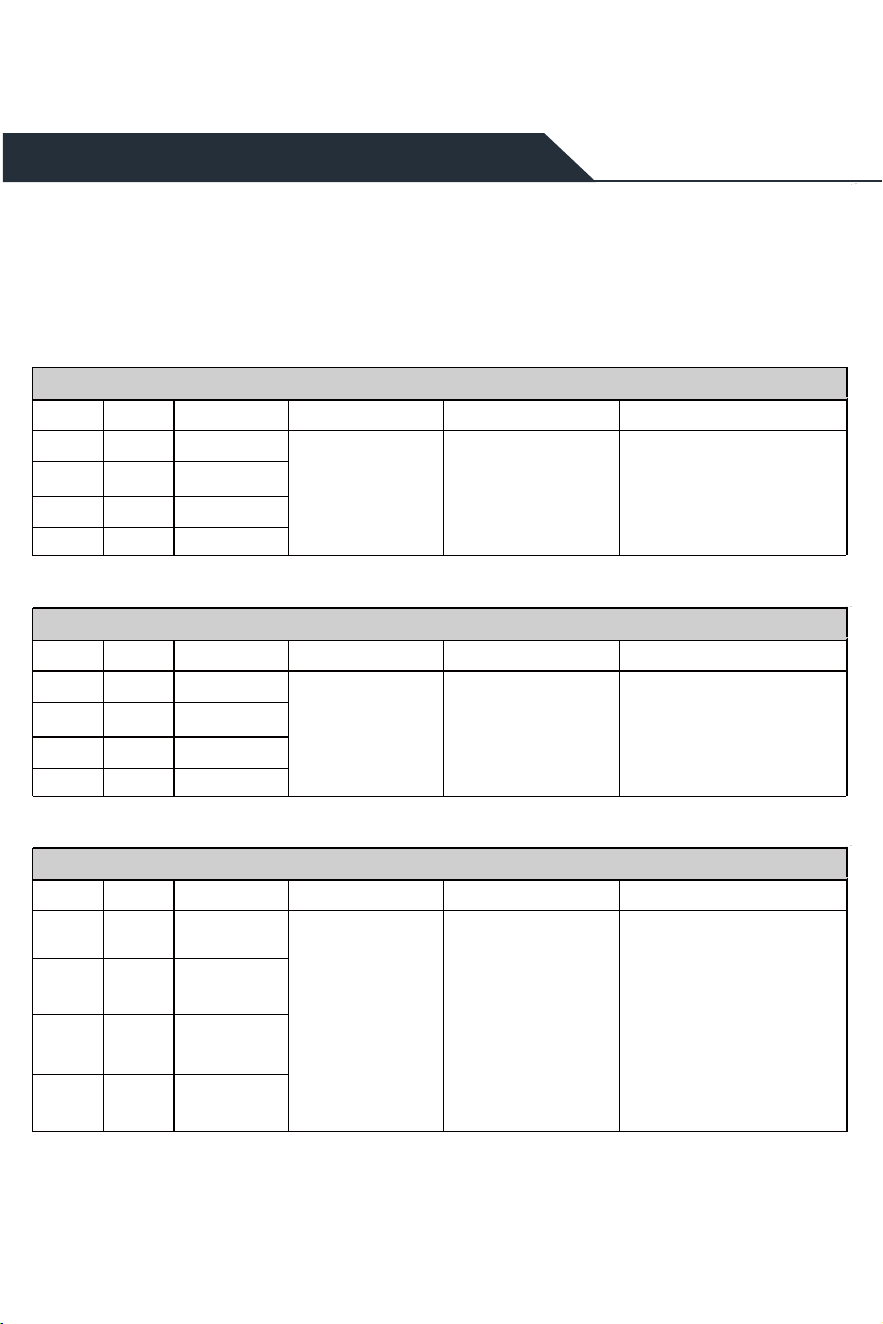
Quick Troubleshooting Guide
OVERLOAD
DL GAIN OUTPUT POWER REASON SOLUTIONLED LIGHT PATTERN
<60dB >=8dBm
Outdoor signal is too
strong
<60dB
<60dB
<60dB
>=8dBm
>=8dBm
>=8dBm
LTE700
CELL800
PCS1900
AWS2100
Have your outdoor antenna
pointed slightly away from the cell
tower
Red(SHDN)
LOOP BACK
DL GAIN OUTPUT POWER REASON SOLUTIONLED LIGHT PATTERN
<60dB <8dBm
<8dBm
<8dBm
<8dBm
<60dB
<60dB
<60dB
LTE700
CELL800
PCS1900
AWS2100
1、Increase vertical and horizontal
distance between the outdoor and
indoor antenna(s).
2、Make the outdoor antenna and the
indoor antenna back to back.
3、Add barriers(e.g. walls)
Yellow(OSC) or
Red(SHDN)
Inadequate separation of
the indoor and outdoor
antennas
POOR SIGNAL
DL GAIN OUTPUT POWER REASON SOLUTIONLED LIGHT PATTERN
>=60dB
>=60dB
>=60dB
>=60dB
--/NEGATIVE
--/NEGATIVE
--/NEGATIVE
--/NEGATIVE
LTE700
CELL800
PCS1900
AWS2100
1、Try adjusting the outdoor
antenna to the best direction
2、Try adjusting the outdoor
antenna to another cell tower
3、Try increasing the height of the
outdoor antenna and make sure
there are no barriers between the
tower and the outdoor antenna
Please try these solutions until the
output power reaches or is over
-5dBm.
Blue(ULN)
Input signal is too weak
Iftheboosterisworkingnormally,nofurtheradjustmentisrequired.
43
Mate 4k Plus / 4k Plus Pro
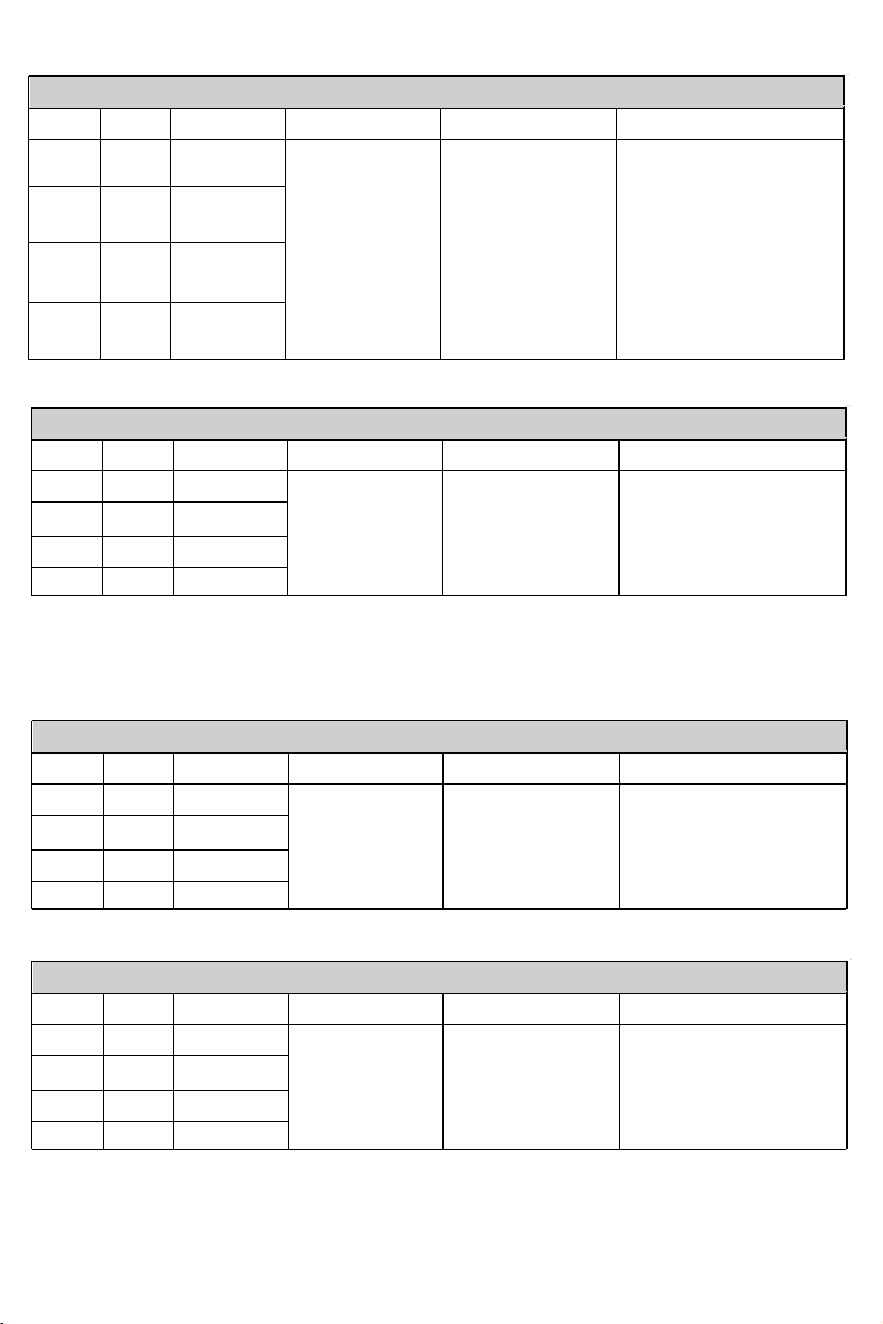
NORMAL
DL GAIN OUTPUT POWER REASON SOLUTIONLED LIGHT PATTERN
>=60dB
>=60dB
>=60dB
>=60dB
>=-5dBm
>=-5dBm
>=-5dBm
>=-5dBm
LTE700
CELL800
PCS1900
AWS2100
Blue(ULN)
Normal but No Boosted Signal
DL GAIN OUTPUT POWER REASON SOLUTIONLED LIGHT PATTERN
>=60dB
>=60dB
>=60dB
>=60dB
>=-5dBm
>=-5dBm
>=-5dBm
>=-5dBm
LTE700
CELL800
PCS1900
AWS2100
Check the band you are using again.
If it stays at band66, get into the
'detail'/ 'Setting' of gagues on Signal
Supervisor and switch o RF switch
of AWS2100, then adjust the
outdoor antenna again. It would be
better if there are two persons and
one can stay near the indoor
antenna to check if the signal is
boosted.
Blue(ULN)
1、The band is not
supported
2、The Signal is from
other Carriers
44
OVERLOAD
DL GAIN OUTPUT POWER REASON SOLUTIONLED LIGHT PATTERN
<60dB >=10dBm
Outdoor signal is too
strong
<60dB
<65dB
<65dB
>=10dBm
>=10dBm
>=10dBm
LTE700
CELL800
PCS1900
AWS2100
Have your outdoor antenna
pointed slightly away from the cell
tower
Red(SHDN)
LOOP BACK
DL GAIN OUTPUT POWER REASON SOLUTIONLED LIGHT PATTERN
<60dB <10dBm
<10dBm
<10dBm
<10dBm
<60dB
<65dB
<65dB
LTE700
CELL800
PCS1900
AWS2100
1、Increase vertical and horizontal
distance between the outdoor and
indoor antenna(s).
2、Make the outdoor antenna and
the indoor antenna back to back.
3、Add barriers(e.g. walls)
Yellow(OSC) or
Red(SHDN)
Inadequate separation of
the indoor and outdoor
antennas
Mate 10k Plus / 10k Plus Pro
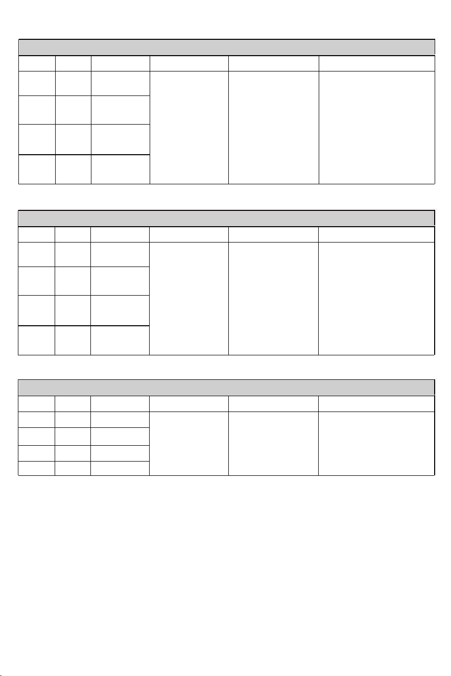
NORMAL
DL GAIN OUTPUT POWER REASON SOLUTIONLED LIGHT PATTERN
>=60dB
>=60dB
>=65dB
>=65dB
>=-5dBm
>=-5dBm
>=-5dBm
>=-5dBm
LTE700
CELL800
PCS1900
AWS2100
Blue(ULN)
Normal but No Boosted Signal
DL GAIN OUTPUT POWER REASON SOLUTIONLED LIGHT PATTERN
>=60dB
>=60dB
>=65dB
>=65dB
>=-5dBm
>=-5dBm
>=-5dBm
>=-5dBm
LTE700
CELL800
PCS1900
AWS2100
Check the band you are using again.
If it stays at band66, get into the
'detail'/ 'Setting' of gagues on Signal
Supervisor and switch o RF switch
of AWS2100, then adjust the
outdoor antenna again. It would be
better if there are two persons and
one can stay near the indoor
antenna to check if the signal is
boosted.
Blue(ULN)
1、The band is not
supported
2、The Signal is from
other Carriers
Note:
Some customers have some misunderstandings about boosters, and we would like to clarify it here:
If you can't even get a stable 1 bar outside the house or on the roof, then we suggest you return it as it won't
work in areas with very weak signal, the same is true of all boosters on the market.
45
POOR SIGNAL
DL GAIN OUTPUT POWER REASON SOLUTIONLED LIGHT PATTERN
>=60dB
>=60dB
>=65dB
>=65dB
--/NEGATIVE
--/NEGATIVE
--/NEGATIVE
--/NEGATIVE
LTE700
CELL800
PCS1900
AWS2100
1、Try adjusting the outdoor
antenna to the best direction
2、Try adjusting the outdoor
antenna to another cell tower
3、Try increasing the height of the
outdoor antenna and make sure
there are no barriers between the
tower and the outdoor antenna
Please try these solutions until the
output power reaches or is over
-5dBm.
Blue(ULN)
Input signal is too weak
46
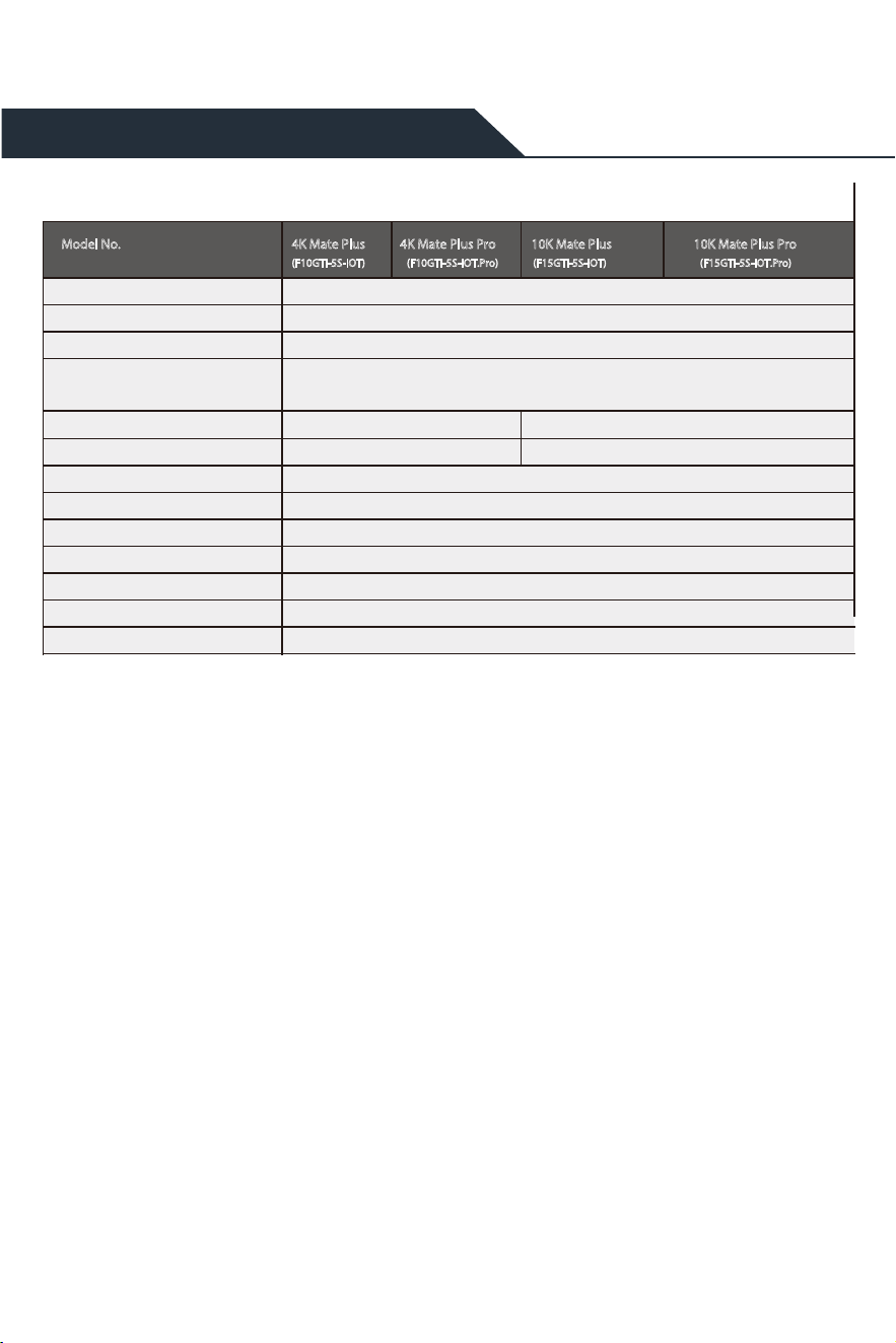
Technical Specications
Notes: Support 5G only that's been or will be deployed in current 4G by DSS
(Dynamic Spectrum Sharing) by carriers.
Working Band
UL F requency R ange(MHz)
DL F requency R ange(MHz)
Supported Standar ds
Max. Gain
Max. output power
MGC (Step Attenuation )
I/O P ort
Impedance
Environment Conditions
Dimensions
Weight
Power Supply
698-716 / 776 – 787 / 824-849 / 1850-1915 / 1710-1755
728-746 / 746 – 757 / 869-894 / 1930-1995 / 2110-2155
Band 12-17 / Band 13 / Band 5 / Band 25-2 / Band 4
65 dB
DL 10 dBm
≥ 25 dB / 1 dB step
50 ohm
IP40
8.0*6.3*1.6 in / 205*160*42mm
≤ 5.0 lbs / 2 kg
Input A C100~240 V , 50/60 Hz, Output DC 12 V / 3 A
70 dB
DL 12 dBm
CDMA , WCDMA , GSM, EDGE, HSP A+, EVDO , L , TE
and all cellular standar ds
4K Mate Plus
(F10GTI-5S-IOT) (F10GTI-5S-IOT.Pro) (F15GTI-5S-IOT) (F15GTI-5S-IOT.Pro)
Model No. 4K Mate Plus Pro 10K Mate Plus 10K Mate Plus Pro
5G
SMA-Female & SMA-Female

47
Authorized Accessories List
Outdoor Antenna & Cable Kit Options
Indoor Antenna & Cable Kit Options
Kit 9-5050
Yagi 9dbi Antenna & 50’ 5D Cable
Kit 11-100400
Yagi 11dbi Antenna & 100' 400 Cable
Kit 11-7550
Yagi 11dbi Antenna & 75' 5D Cable
Kit 11-100500
Yagi 11dbi Antenna & 100' 5D Cable
Kit 10-3050
Panel 10dbi Antenna & 30' 5D Cable
Kit 10-50400
Panel 10dbi Antenna & 50' 400 Cable
Kit 10-5050
Panel 10dbi Antenna & 50' 5D Cable
Kit 10-75400
Panel 10dbi Antenna & 75' 400 Cable
Kit 10-100400
Panel 10dbi Antenna & 100' 400 Cable
Kit 10-7550
Panel 10dbi Antenna & 75' 5D Cable
Kit 10-10050
Panel 10dbi Antenna & 100' 5D Cable
Kit 9-50400
Yagi 9dbi Antenna & 50' 400 Cable
Kit 9-75400
Yagi 9dbi Antenna & 75' 400 Cable
Kit 9-100400
Yagi 9dbi Antenna & 100' 400 Cable
Kit 9-7550
Yagi 9dbi Antenna & 75' 5D Cable
Kit 9-10050
Yagi 9dbi Antenna & 100' 5D Cable
Kit 7-3050
Panel 7dbi Antenna & 30' 5D Cable
Kit 7-50400
Panel 7dbi Antenna & 50' 400 Cable
Kit 7-5050
Panel 7dbi Antenna & 50' 5D Cable
Kit 7-75400
Panel 7dbi Antenna & 75' 400 Cable
Kit 7-100400
Panel 7dbi Antenna & 100' 400 Cable
Kit 7-7550
Panel 7dbi Antenna & 75' 5D Cable
Kit 7-10050
Panel 7dbi Antenna & 100' 5D Cable
Kit 5-30400
Omni 5dbi Antenna & 30' 400 Cable
Kit 5-3050
Omni 5dbi Antenna & 30' 5D Cable
Kit 5-50400
Omni 5dbi Antenna & 50' 400 Cable
Kit 5-5050
Omni 5dbi Antenna & 50' 5D Cable
Kit 5-75400
Omni 5dbi Antenna & 75' 400 Cable
Kit 5-10400
Omni 5dbi Antenna & 100' 400 Cable
Kit 5-7550
Omni 5dbi Antenna & 75' 5D Cable
Kit 5-10050
Omni 5dbi Antenna & 100' 5D Cable
Kit 72-5050-50
2 Panel 7dbi Antenna with50' 5D N male
& 2-Way Splitter
Kit 52-5050-50
2 Whip 5dbi Antenna &50' 5D Cable
& 2-Way Splitter
Kit 102-5050-50
2 Panel 10dbi Antenna with50'5D N male
& 2-Way Splitter
Kit 103-7550-50
3 Panel 10dbi Antenna & 75' 5D Cable
& 3-Way Splitter
kit 104-7550-50
4 Panel 10dbi Antenna & 75' 5D Cable
& 3 2-Way Splitter
Kit 73-7550-50
3 Panel 7dbi Antenna & 75' 5D Cable
& 3-Way Splitter
kit 74-7550-50
4 Panel 7dbi Antenna & 75' 5D Cable
& 3 2-Way Splitter
Kit 3-30400
Omni 3dBi Antenna with 30' 400 Cable
Kit 3-5050
Omni 3dBi Antenna & 50' 5D Cable
Kit 3-7550
Omni 3dBi Antenna & 75' 5D Cable
Kit 3-10050
Omni 3dBi Antenna & 100' 5D Cable
Kit 3-30400
Omni 3dBi Antenna with 30' 400 Cable
Kit 3-50400
Omni 3dBi Antenna & 50' 400 Cable
Kit 32-50400-50
2Omni 3dBi Antenna & 50' 400 Cable
& 2-Way Splitter
Kit 33-50400-50
3 Omni 3dBi Antenna & 50' 400 Cable
& 3-Way Splitter
Kit 34-50400-50
4 Omni 3dBi Antenna &50' 400 Cable
&3 2-Way Splitter

48
FCC RF EXPOSURE STATEMENT
This equipment complies with FCC radiation exposure limits set forth for an uncontrolled
environment. End users must follow the specic operating instruction for satisfying RF
exposure compliance. This transmitter must not be colocated or operating in conjunction
with any other antenna or transmitte.his equipment should be installed andoperated
with minimum distance 20cm between the radiator& your body.
ISEDC RF EXPOSURE STATEMENT
The devices is compliance with RF exposure limits. The minimum distance from body to
use the device is 20 CM.
Le présent appareil est conforme aux conformité ou aux limites d’intensité de champ
RF. La distance minimale du corps à utiliser le dispositif est de 20 CM.
This device complies with part 15 of the FCC Rules. Operation is subject to the follow-
ing two conditions: (1) This device may not cause harmful interference, and (2) this
device must accept any interference received, including interference that may cause
undesired operation.
FCC and ISEDC Statements
This equipment has been tested and found to comply with the limits for a Class B digital
device, pursuant to part 15 of the FCC Rules. These limits are designed to provide reason-
able protection against harmful interference in a residential installation. This equipment
generates, uses and can radiate radio frequency energy and, if not installed and used in
accordance with the instructions, may cause harmful interference to radio communica-
tions. However, there is no guarantee that interference will not occur in a particular
installation. If this equipment does cause harmful interference to radio or television
reception, which can be determined by turning the equipment o and on, the user is
encouraged to try to correct the interference by one or more of the following measures:
• Re-orient or relocate the receiving antenna.
• Increase the separation between the equipment and receiver
• Connect the equipment into an outlet on a circuit dierent from that to
which the receiver is connected
• Consult the dealer or an experienced radio/TV technician for help
Changes or modications not expressly approved by HiBoost could void the user’s
authority to operate the equipment. For a complete list of antennas and cables approved
for use with these boosters see Authorized Kitting Options

FCC 27.50(d)(4) Statement: Fixed, mobile, and portable (handheld) stations operat-
ing in the 1710-1755 MHz band are limited to 1-watt EIRP. Fixed stations operating in the
1710-1755 MHz band are limited to a maximum antenna height of 10 meters above
ground.
FURTHER INFORMATION ON SIGNAL BOOSTER END-USE REGISTRATION
The following links are the currently active contacts for booster registration with U.S.
wireless providers:
https://www.uscellular.com/uscellular/support/fcc-booster-registration.jsp https://ww-
w.sprint.com/legal/fcc_boosters.html
https://www.verizonwireless.com/solutions-and-services/acces-
sories/register-signal-booster/ https://support.t-mobile.com/docs/DOC-9827 https://se-
curec45.securewebsession.com/attsignalbooster.com/
ISEDC Statement: This device complies with Innovation, Science, and Economic
Development Canada licence-exempt RSS standard(s). Operation is subject to the
following two conditions:
(1) this device may not cause interference, and
(2) this device must accept any interference, including interference that may cause
undesired operation of the device.
Le présent appareil est conforme aux CNR d' Innovation, Sciences et Développement
économique Canada applicables aux appareils radio exempts de licence. L'exploitation
est autorisée aux deux conditions suivantes :
(1) l'appareil nedoit pas produire de brouillage, et
(2) l'utilisateur de l'appareil doit accepter tout brouillage radioélectrique subi, même si le
brouillage est susceptible d'en compromettre le fonctionnement.
This device complies with Innovation, Science and Economic Development Canada
ICES-003 Compliance Label: CAN ICES-3 (B)/ NMB-3(B). Le présent appareil est conforme
Innovation, science et développement économique Canada ICES-003 Étiquette de
conformité: CAN ICES-3 (B) / NMB-3 (B).
Please follow the link to access the CPC-2-1-05:
http://www.ic.gc.ca/eic/site/smt-gst.nsf/eng/sf08942.html
49
50
This is a CONSUMER device.
BEFORE USE, you MUST REGISTER THIS DEVICE with your wireless provider and have your
provider’s consent. Most wireless providers consent to the use of signal boosters. Some
providers may not consent to the use of this device on their network.If you are unsure,
contact your provider.
In Canada, BEFORE USE, you must meet all requirements set out in ISED CPC-2-1-05.
You MUST operate this device with approved antennas and cables as specified by the
manufacturer. Antennas MUST be installed least 20 cm(8 inches)from(i. e..MUST NOT be
installed within 20 cm of)any person.
You MUST cease operating this device immediately if requested by the FCC(or ISED in
Canada)or a licensed wireless service provider.
WARNING. E911 location information may not be provided or may be inaccurate for calls
served by using this device.
This device may be operated ONLY in a fixed location(i.e., may operate in a fixed location

51
30-Day Money-Back Guarantee: If for any reason the performance of any product is not
acceptable, the product may be returned to the reseller within 30-days with proof of
purchase. Please contact the customer support team.
3-Year Warranty: Signal boosters and kits are warranted for 3 years. We will repair or
replace the unit and will cover the cost of delivery back to consumers located within
the continental US and Canada. We will only cover shipping to our oce if the booster
was delivered to you recently, and was delivered defective.
Customers can choose to return the signal boosters and kits directly to the manufacturer at
the purchaser's expense with a dated proof of purchase and a Returned Material Authoriza-
tion (RMA) number supplied by us. RMA numbers may be obtained by contacting customer
support at 972-870- 5666 or support @hiboost.com
This warranty does not apply to any signal boosters or kits determined by us to have been
subjected to tampering, misuse, abuse, neglect, or mishandling that alters or damages
physical or electronic properties.
We are not liable for any Signal Supervisor application network connectivity issues. The cell
phone signal booster relies on a strong, continuous and reliable connection to the internet
in order to communicate with the cell phone application. For all Signal Supervisor Applica-
tion related issues, please check your network strength and call our technical support.
Failure to use a surge-protected AC power strip with at least a 1000 Joule rating will void
your warranty. Damage caused by lightning is not covered by this warranty.
All of the products that are packaged with other accessory products are intended for resale
and used as a single integrated system. Such product kits are required to be sold to the
end-users or subsequent reseller as packaged.
Return and Warranty Policies