
Technical Support and E-Warranty Certificate www.vevor.com/support
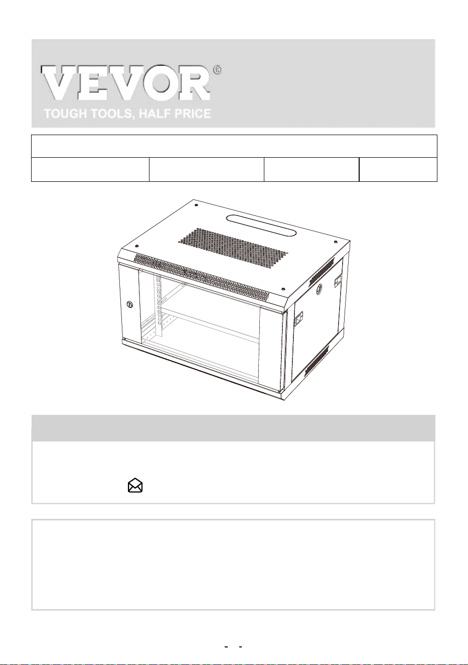
WALL MOUNT
SERVER ENCLOSURE
USER MANUAL
We continue to be committed to provide you tools with competitive price.
"Save Half", "Half Price" or any other similar expressions used by us only represents an estimate
of savings you might benefit from buying certain tools with us compared to the major top brands
and doses not necessarily mean to cover all categories of tools offered by us. You are kindly
reminded to verify carefully when you are placing an order with us if you are actually saving half
in comparison with the top major brands.
THIS MANUAL APPLIES TO THE FOLLOWING SKUS:
W26406 W26409 W26412 W36412
NEED HELP? CONTACT US!
Have product questions? Need technical support? Please feel free to
contact us:
CustomerService@vevor.com
This is the original instruction, please read all manual instructions
carefully before operating. VEVOR reserves a clear interpretation of
our user manual. The appearance of the product shall be subject to the
product you received. Please forgive us that we won't inform you again
if there are any technology or software updates on our product.
1
WALL MOUNT SERVER
ENCLOSURE

Thank you for purchasing the Performance Series Wall Mount Cabinet
from VEVOR.
Every effort has been made to ensure the accuracy of the information in
this product manual.
Keep the enclosure free from moisture, extremes of temperature, com-
bustible substances and gases, conductive pollutants, dust, and direct
sunlight in a controlled indoor environment. Allow sufficient room for
appropriate ventilation at the front and back of the enclosure. The
enclosure's external ventilation openings must not be blocked, covered,
or inserted with items.
Please call or email us if you have any concerns about the installation or
use of your product. Please inspect the product for any missing or
defective components. Ask VEVOR for help if any component is broken
or missing. If the product has been affected, do not try to install or use it.
To prevent harm during assembly, place the product contents on card-
board or another safe surface. Improper installation or use of this prod-
uct can result in product damage, other damage to equipment, or
personal injury.
It is advised that the installation be performed by a professional installer.
VEVOR cannot be held liable for equipment damage or physical injuries
resulting from inappropriate product usage or installation. Please ensure
that the equipment stored/mounted should not exceed the stated weight
capacity.
Use of Trademarks, Registered Trademarks, and other Protected
Names and Symbols
This manual may make reference to trademarks, registered trademarks,
and other protected names and/or symbols of third-party companies not
related in any way to VEVOR. These references are provided for infor-
mational purposes only and do not represent an endorsement of a
IMPORTANT SAFETY INSTRUCTIONS
2
5
1
F
A
3
4
D
E
2
6
8
7
9
4
10
B
C
product or service by VEVOR, or an endorsement of the product(s) to
which this manual applies by the third-party company in question.
Regardless of any direct acknowledgment elsewhere in the body of this
document, VEVOR hereby acknowledges that all trademarks, registered
trademarks, service marks, and other protected names and/or symbols
contained in this manual and related document are the property of their
respective holders.
Limitations of Liability: VEVOR will not be responsible for any injury or
damage, whether direct or indirect, special, punitive, incidental, or
consequential damages (including, but not limited to, lost profits or
revenue, loss of use, lost business opportunities, or loss of goodwill), or
the costs of procuring substitute products, arising out of or in connection
with the use of the product. In no case can seller's gross accumulated
liability, arising from all causes of action and theories of liability, exceed
the total sums actually charged by customer to seller under the order
giving rise to any liability hereunder.
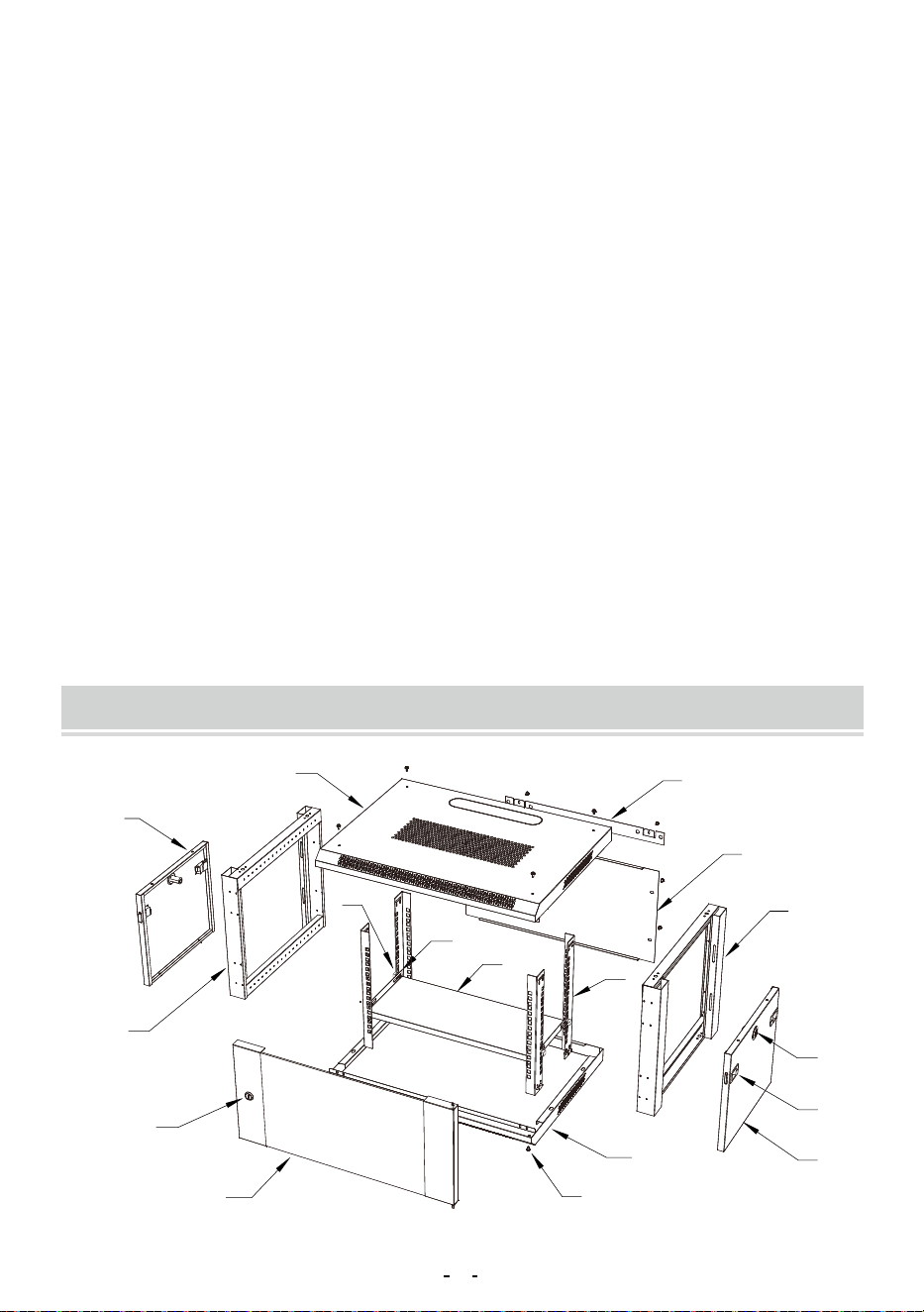
PARTS IDENTIFICATION
3
6
A
2
5
A
1. Top Panel
2. Bottom Panel
3. Front Door
4. Side Panels
5. Left Frame
6. Right Frame
7. Rear panel
8. Rear suspension
9. Vertical Mounting Rails
10 . Pallet
x1
x1
x1
x2
x1
x1
x1
x1
x4
x1
A: M5 Screws
B: M6 Hex Head Screws
C: M6 Cage Nuts
D: Side Panel Latches
E: Side Panel Lock Kitx2
F: Front Door Lock Kit
G: M10 Expansion screws
H:hex brass nut for screw bolt
I:expansion bolts
x40
x15
x15
x4
x2
x1
x4
x1
x4
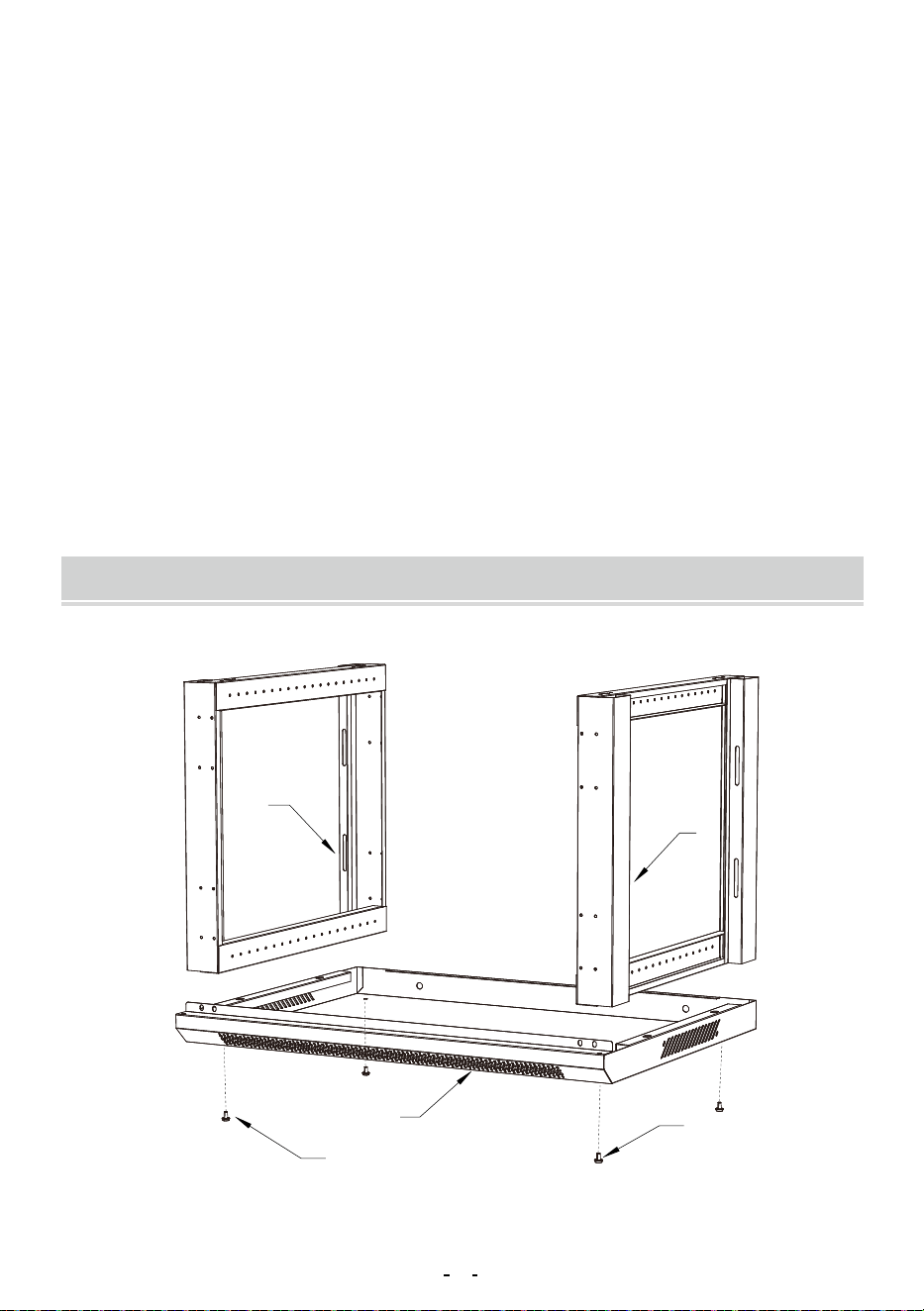
ENCLOSURE INSTALLATION
4
9
9
A
1
A
1: Insert the Left Frame (#5) and the Right Frame (#6) into the Bottom
Panel (#2), Secure with M5 Screws (A) .
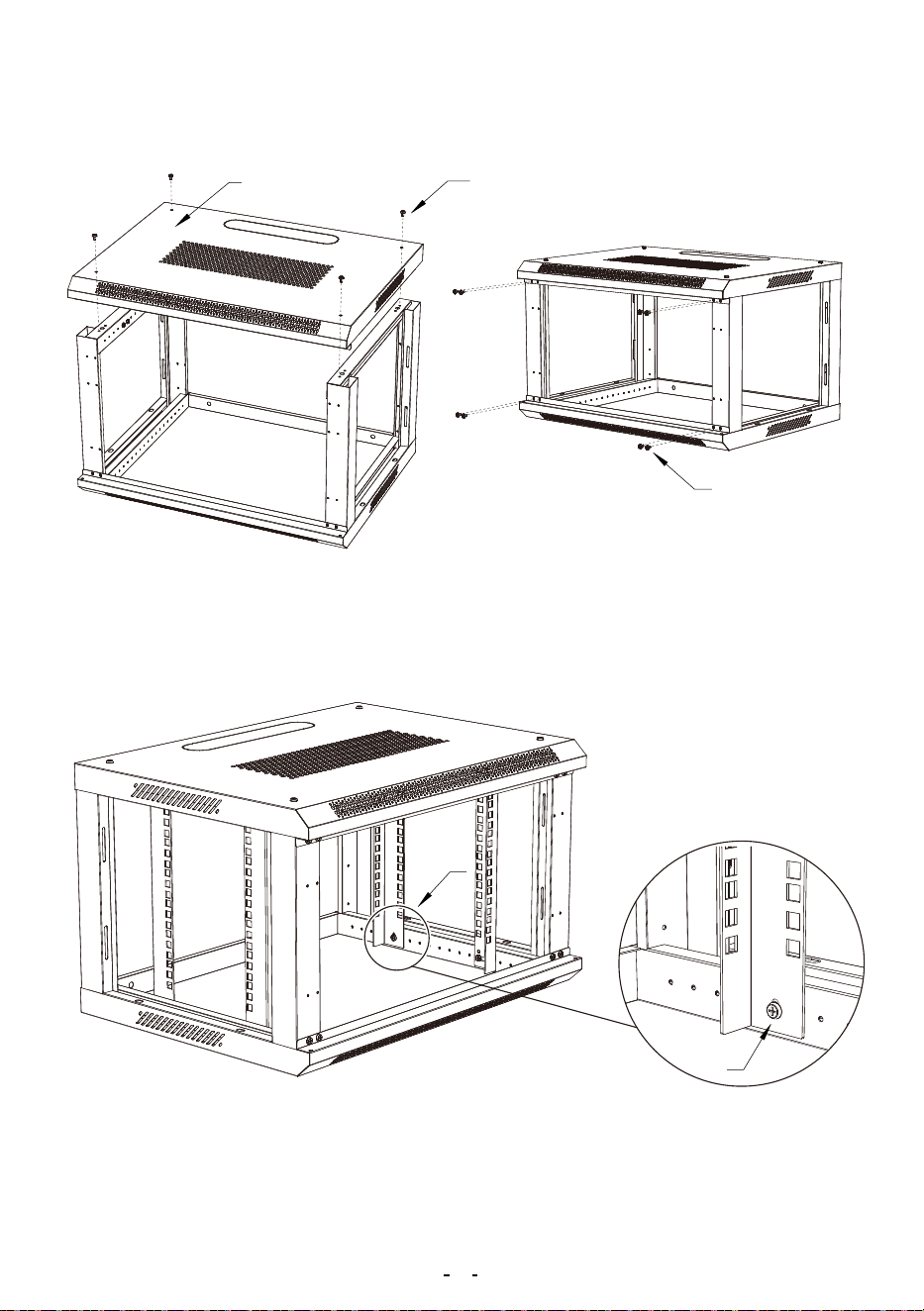
3: Install the 4 Vertical Mounting Rails (#9) into place at the desired depth
using M5 Screws(A)for each Vertical Mounting Rails (#9).
Note: Please consider the equipment you plan to install within the
2: Place the Top Panel (#1) onto the Left Frame (#5) and the Right
Frame (#6). Secure with M5 Screws(A) .
5
4
D
E
C
B
10
C
B
enclosure while deciding the appropriate mounting depth. Make sure the
rail depth on both sides of the cabinet is the same.
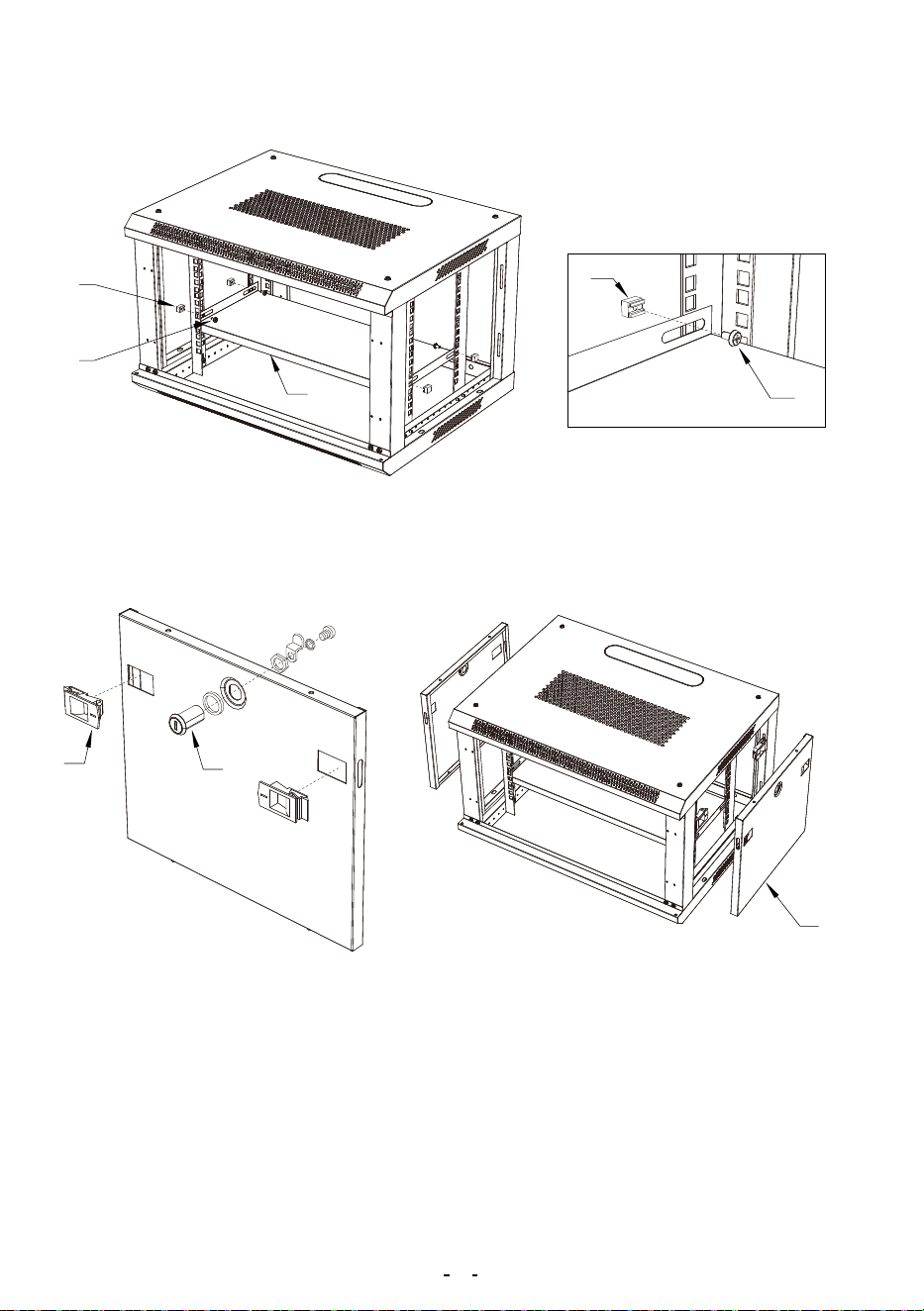
4: Install the Pallet (#10) into place at the desired height ,Secure with M6
Hex Head Screws (B) and M6 Cage Nuts (C).
5: Install the Side Panel Latches ( D) and the Side Panel Lock Kit ( E) on
the two Side Panels (#4).
6: Install the two Side Panels (#4) into place using the Side Panel Latch-
es(E). Once each Side Panel (#4) is in place, check to see whether the
Side Panel Lock locks properly.
6
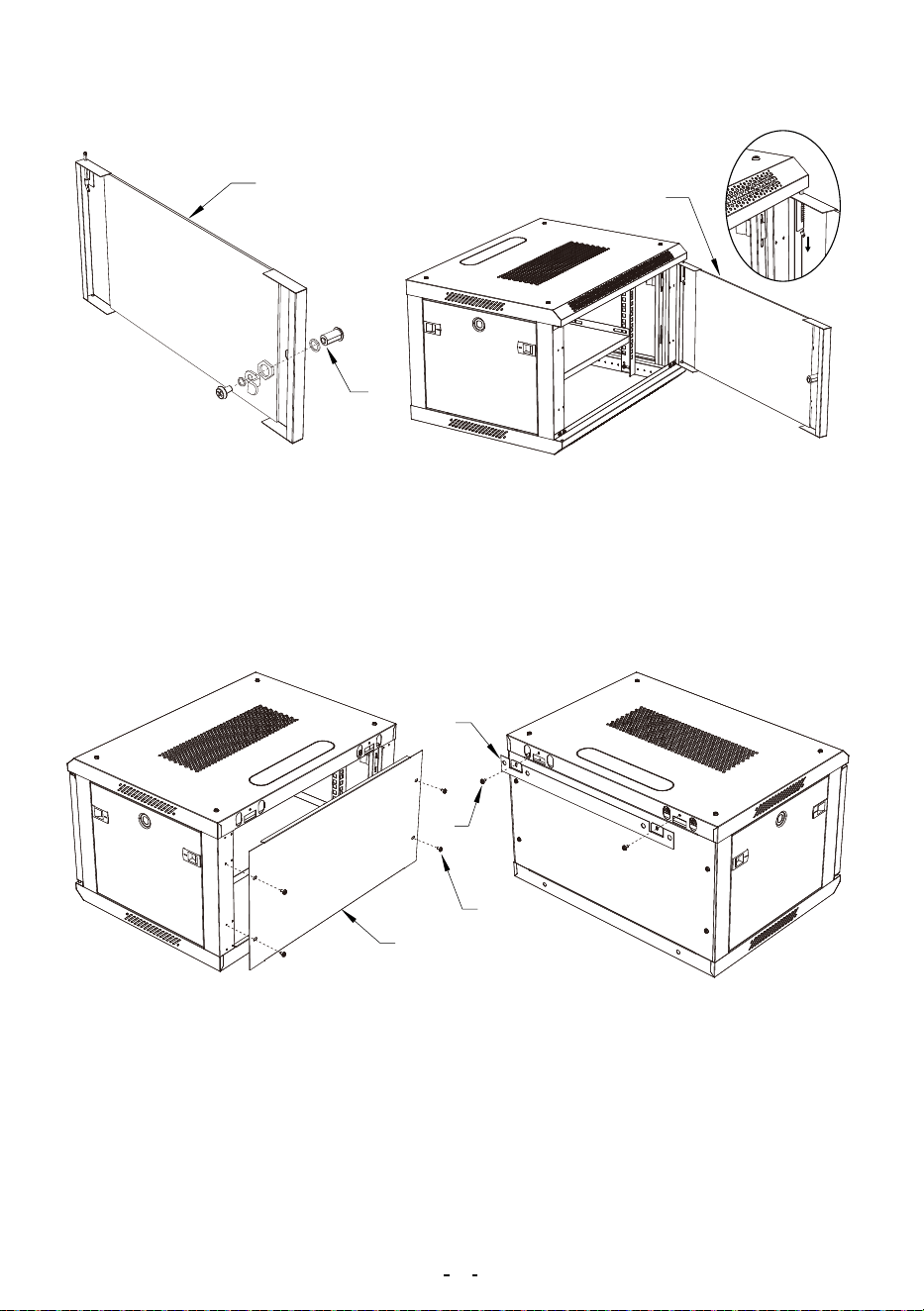
8
A
7
A
3
3
F
7: Install the Front Door Lock (F) on the Front Door (#3).
8: Position the Front Door (#3) so that the top and bottom pins are aligned
with the hinge hole located in the enclosure. Insert the bottom fixed pin
into the bottom hinge hole. Pull the top spring pin down into the hole in the
top corner and release it.
9: Install the Rear panel ( #7) and the Rear suspension (#8) ,Secure
with M5 Screws(A) .
7
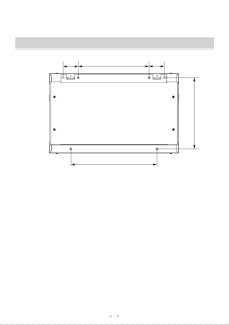
400
330
33070
70
WALL MOUNTING THE ENCLOSURE
1: Attach the rack to a wall or other suitable mounting surface using M10
Expansion screws(G). The mounting hole distance is shown in Fig, apart
to accommodate standard stud placement as reflected in the diagram.
Warning: Do not attempt to mount to wall when equipment is mount-
ed inside the enclosure. The enclosure has a weight capacity of 100
pounds. Make sure the type of wall structure and mounting hardware
that you are using will properly support the weight of the enclosure
and equipment.For the safety,two people to install.
8
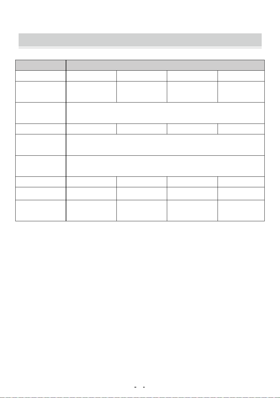
PRODUCT PARAMETER
Wall Mount Server EnclosureName
Model
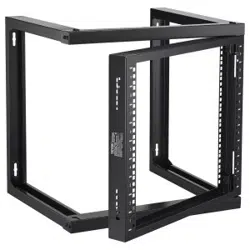
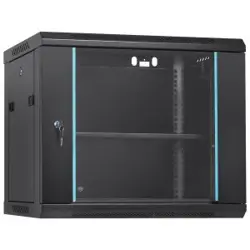
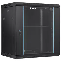
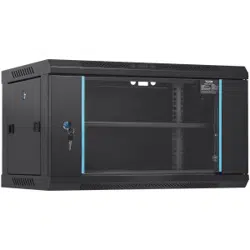
W26406 W26409 W36412
Tempered Glass
Door
Tempered Glass
Door
Tempered Glass
Door
Mesh Iron Door
W26412
6U 9U 12U 12U
350 *450*600mm 500*450*600mm 640*450*600mm
660*545*230mm 660*545*230mm 710*700*235mm
640*450*600mm
710*700*235mm
N.W.: 14.45 Kg N.W.: 17.76Kg
100 Ibs
200 Ibs
19''
N.W.: 19.28Kg
G.W.: 16.45 Kg G.W.: 19.76Kg
N.W.: 21.08Kg
G.W.: 23.43Kg G.w.: 21.63Kg
Door
Installation
Width Standard
Height
Ground-Mounted
Load-Bearing
Wall-Mounted
Load-Bearing
Product Size
Package Size
Weight
9

Address:Baoshanqu Shuangchenglu 803long 11hao 1602A-1609shi
Shanghai
Imported to USA: VEVOR STORE INC, 9448 RINCHMOND PL #E
RANCHO CUCAMONGA, California, 91730 United States of America
Made In China
10

Technical Support and E-Warranty Certificate
www.vevor.com/support