
Technical Support and E-Warranty Certificate
www.vevor.com/support
Model:
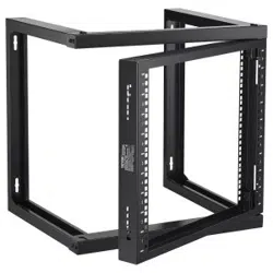
Wall Mount Server Rack
SPT-505-09
We continue to be committed to provide you tools with competitive price.
"Save Half", "Half Price" or any other similar expressions used by us only represents an
estimate of savings you might benefit from buying certain tools with us compared to the major
top brands and does not necessarily mean to cover all categories of tools offered by us. You
are kindly reminded to verify carefully when you are placing an order with us if you are
actually saving half in comparison with the top major brands.

- 1 -
Have product questions? Need technical support? Please feel free to
contact us:
Technical Support and E-Warranty Certificate
www.vevor.com/support
NEED HELP? CONTACT US!
This is the original instruction, please read all manual instructions
carefully before operating. VEVOR reserves a clear interpretation of our
user manual. The appearance of the product shall be subject to the
product you received. Please forgive us that we won't inform you again if
there are any technology or software updates on our product.
Warning-To reduce the risk of injury, user must read
instructions manual carefully.
Server Rack Shelf
Wall Mount Server Rack

- 2 -
PRODUCT DIAGRAM
SPECIFICATION DA
U Type Support x2
Crossbeam x2
Door Set x1
REQUIREMENT
Two People (for assembly)
Electrical Phillips Head Screwdriver x 1

- 3 -
SPECIFICATION DATA
SPECIFICATION DA

- 4 -
SERVER RACK INSTALLATION
1. Insert the Bottom Crossbeam into left U Type Support and right
U Type Support, Secure with 8pcs M5 assembly fix Screws .See Figure 1.
Notes:during assembly,need notice the Crossbeam direction,make sure
the vertical mounting holes are aligned.
2. Insert the Top Crossbeam into left U Type Support and right U
Type Support, Secure with 8pcs M5 assembly fix Screws .See Figure 2.
Notes:during assembly,need notice the Crossbeam direction,make sure
the vertical mounting holes are aligned.
Figure 1 Figure 2
3. Pull the Door Set’s 4pcs door latches on unlock position as
follows,ready to assembly door set on the Rack.See Figure 3
Figure 3
4. Put the Door Set on the frame showed position,then lock the right side

- 5 -
of door set’s 2pcs door latches on the Rack one by one,make sure the door
can be open and close smoothly.See Figure 4
Figure 4
5. Adopts same step as step 4.lock the left side of door set’s 2pcs door
latches on the frame one by one.make sure the door set is fixed.See
Figure 5
Figure 5
WALL MOUNT INSTALLATION
1. First put the server rack on the wall or other suitable mounting
surface,on the suitable position to mark mounting holes position by colored
pen.
Or can directly according to the wall mounting hole distance L*H
473*390mm to mark mounting holes position.
2. Adopts electric drill to drill marked 4pcs diameter 14mm holes,then

- 6 -
mounting and fix the M10 Expansion screws into the holes.
3. Fix the server rack on the the M10 Expansion screws,tight the
expansion screw’s nut.
EQUIPMENT INSTALLATION
Use the included M6 cage nuts,screws to install equipment into the wall
mount server rack.
4. Insert the wing(side)of an M6 cage nut into the back of the desired cage
nut hole.
5. Apply pressure by hand or with the cage nut tool,to insert the second
wing of the M6 cage nut into the desired cage nut hole.
6. Repeat steps 1 and 2 to insert the desired number of cage nuts for the
application.
7. Align the Mounting holes in the equipment with the M6 cage nuts
installed in steps 1-3.
8. Thread an M6 screws,Repeat until the desired number of M6 screws
have been prepared.
9. Tighten the screws,using a phillips head screwdriver.

Technical Support and E-Warranty Certificate
www.vevor.com/suppor

"Économisezlamoitié","Moitiéprix"outouteautreexpressionsimilairequenousutilisonsnereprésente
qu'uneestimationdeséconomiesdontvouspourriezbénéficierenachetantcertainsoutilscheznousparrapport
auxgrandesmarquesetnesignifiepasnécessairementcouvrirtouteslescatégoriesd'outilsproposés.parnous.
Nousvousrappelonsdebienvouloirvérifierattentivementlorsquevouspassezunecommandechez
noussivouséconomisezréellementlamoitiéparrapportauxgrandesmarques.
Nouscontinuonsànousengageràvousfournirdesoutilsàdesprixcompétitifs.
Modèle:
Assistancetechniqueetcertificatdegarantie
électroniquewww.vevor.com/support
SPT50509
Rackdeserveuràmontagemural
Machine Translated by Google

Étagèrederackdeserveur
Ils'agitdesinstructionsoriginales,veuillezlireattentivementtouteslesinstructionsdu
manuelavantdel'utiliser.VEVORseréserveuneinterprétationclairedenotremanueld'utilisation.
L'apparenceduproduitdépendduproduitquevousavezreçu.Veuilleznouspardonner
quenousnevousinformeronspluss'ilyadesmisesàjourtechnologiquesoulogiciellessurnotre
produit.
Vousavezdesquestionssurlesproduits?Besoind'uneassistancetechnique?N'hésitezpas
ànous
contacter:Supporttechniqueetcertificatdegarantieélectronique
www.vevor.com/support
Avertissement:Pourréduirelerisquedeblessure,l'utilisateurdoitlire
attentivementlemanueld'instructions.
BESOIND'AIDE?CONTACTEZNOUS!
Rackdeserveuràmontagemural
1
Machine Translated by Google

x1
Ensembledeporte
Deuxpersonnes(pourl'assemblage)
TournevisélectriqueàtêtePhillipsx1
SupportdetypeU
Traverse
x2
x2
SPÉCIFICATIONDA
EXIGENCE
SCHÉMADUPRODUIT
2
Machine Translated by Google

SPÉCIFICATIONDA
DONNÉESDESPÉCIFICATION
3
Machine Translated by Google

2.InsérezlatraversesupérieuredanslesupportdetypeUgaucheetdanslesupportUdroit.
Typedesupport,sécuriséavec8visdefixationd'assemblageM5.Voirlafigure2.
Remarques:lorsdel'assemblage,vousdeveznoterladirectiondelatraverse,assurezvous
3.Tirezles4loquetsdeportedel'ensembledeporteenpositiondedéverrouillagecomme
Remarques:lorsdel'assemblage,vousdeveznoterladirectiondelatraverse,assurezvous
lestrousdemontageverticauxsontalignés.
SupportdetypeU,sécuriséavec8visdefixationd'assemblageM5.Voirlafigure1.
1.InsérezlatraverseinférieuredanslesupportdetypeUgaucheetdroit
suit,prêtàassemblerlaportesurlerack.Voirlafigure3
Figure1
lestrousdemontageverticauxsontalignés.
figure3
4.Placezl'ensembledeportesurlapositionindiquéeparlecadre,puisverrouillezlecôtédroit.
Figure2
INSTALLATIONDURACKDESERVEUR
4
Machine Translated by Google

INSTALLATIONSURMONTAGEMURAL
Figure4
5.Adoptelamêmeétapequel'étape4.Verrouillezlecôtégauchedes2loquetsdeportede
l'ensembledeportesurlecadreunparun.Assurezvousquel'ensembledeporteestfixé.
VoirFigure5.
1.Placezd'abordlerackdeserveursurlemurousuruneautresurfacedemontage
appropriée,àl'endroitappropriépourmarquerlapositiondestrousdemontageàl'aided'unstylode
couleur.
Figure5
des2loquetsdeportedujeudeportessurlerackunparun,assurezvousquelaportepeutêtre
ouverteetferméeendouceur.Voirlafigure4.
OupeutdirectementenfonctiondeladistancedestrousdemontagemuralL*H
473*390mmpourmarquerlapositiondestrousdemontage.
2.Adopteuneperceuseélectriquepourpercer4trousmarquésde14mmdediamètre,puis
5
Machine Translated by Google

écrou.INSTALLATIONDEL'ÉQUIPEMENT
troud'écrou.
9.Serrezlesvisàl'aided'untourneviscruciforme.
4.Insérezl'aile(côté)d'unécrouàcageM6àl'arrièredelacagesouhaitée.
ontétépréparés.
3.Fixezlerackduserveursurlesvisd'extensionM10,serrezles
5.Appliquezunepressionàlamainouavecl'outild'écrouàcagepourinsérerledeuxième
6.Répétezlesétapes1et2pourinsérerlenombresouhaitéd'écrousàcagepourle
montageetfixezlesvisd'expansionM10danslestrous.
l'ailedel'écroucageM6dansletroud'écroucagesouhaité.
7.Alignezlestrousdemontagedel'équipementaveclesécrouscageM6.
visd'expansion
application.
monterlerackduserveur.
8.EnfilezunevisM6,répétezjusqu'àobtenirlenombresouhaitédevisM6.
UtilisezlesécrousàcageM6etlesvisincluspourinstallerl'équipementdanslemur.
installéauxétapes1à3.
6
Machine Translated by Google

Assistancetechniqueetcertificatdegarantie
électroniquewww.vevor.com/suppor
Machine Translated by Google

Wir sind weiterhin bestrebt, Ihnen Werkzeuge zu wettbewerbsfähigen Preisen anzubieten.
„Sparen Sie die Hälfte“, „Halber Preis“ oder andere ähnliche Ausdrücke, die wir verwenden, stellen nur eine
Schätzung der Ersparnis dar, die Sie beim Kauf bestimmter Werkzeuge bei uns im Vergleich zu den großen
Topmarken erzielen können, und decken nicht unbedingt alle von uns angebotenen Werkzeugkategorien ab. Wir
möchten Sie freundlich daran erinnern, bei Ihrer Bestellung bei uns sorgfältig zu prüfen, ob Sie im Vergleich
zu den großen Topmarken tatsächlich die Hälfte sparen.
Modell:
Technischer Support und E-Garantie-Zertifikat
www.vevor.com/support
SPT-505-09
Server-Rack zur Wandmontage
Machine Translated by Google

Server-Rack-Regal
Dies ist die Originalanleitung. Bitte lesen Sie alle Anweisungen sorgfältig durch, bevor Sie
das Gerät in Betrieb nehmen. VEVOR behält sich eine klare Auslegung unserer Bedienungsanleitung
vor. Das Erscheinungsbild des Produkts richtet sich nach dem Produkt, das Sie erhalten
haben. Bitte verzeihen Sie uns, dass wir Sie nicht erneut informieren, wenn es Technologie- oder
Software-Updates für unser Produkt gibt.
Haben Sie Fragen zum Produkt? Benötigen Sie technischen Support? Bitte kontaktieren Sie uns:
Technischer
Support und E-Garantie-Zertifikat www.vevor.com/support
Warnung: Um das Verletzungsrisiko zu verringern, muss der Benutzer
die Bedienungsanleitung sorgfältig lesen.
Brauchen Sie Hilfe? Kontaktieren Sie uns!
Server-Rack zur Wandmontage
- 1 -
Machine Translated by Google

x1
ÿ Türset
ÿ Zwei Personen (für die Montage)
ÿ Elektrischer Kreuzschlitzschraubendreher x 1
x2
x2
ÿ U-Typ-Unterstützung ÿ
Querträger
SPEZIFIKATION DA
PRODUKTDIAGRAMM
ERFORDERNIS
- 2 -
Machine Translated by Google

SPEZIFIKATION DA
SPEZIFIKATIONSDATEN
- 3 -
Machine Translated by Google

2. Setzen Sie den oberen Querträger in die linke U-Stütze und die rechte U-
Typunterstützung, Befestigung mit 8 M5-Montagebefestigungsschrauben. Siehe Abbildung 2.
Hinweise: Bei der Montage müssen Sie die Richtung des Querträgers beachten.
die vertikalen Befestigungslöcher sind ausgerichtet.
Hinweise: Bei der Montage müssen Sie die Richtung des Querträgers beachten.
die vertikalen Befestigungslöcher sind ausgerichtet.
U-Typ-Stütze, mit 8 M5-Montagebefestigungsschrauben sichern. Siehe Abbildung 1.
1. Den unteren Querträger in die linke U-Stütze und die rechte
Abbildung 1 Figur 2
folgt, bereit zur Montage der Tür am Rack. Siehe Abbildung 3
Figur 3
3. Ziehen Sie die 4 Türriegel des Türsets in die Entriegelungsposition.
4. Setzen Sie das Türset in die gezeigte Position des Rahmens und verriegeln Sie dann die rechte Seite
SERVER-RACK-INSTALLATION
- 4 -
Machine Translated by Google

WANDMONTAGE-INSTALLATION
Abbildung 5
1. Platzieren Sie das Server-Rack zunächst an der Wand oder einer anderen geeigneten
Montagefläche und markieren Sie die Position der Montagelöcher mit einem Farbstift an der entsprechenden
Stelle.
Abbildung 4
5. Führen Sie die gleichen Schritte wie in Schritt 4 aus. Verriegeln Sie die beiden Türriegel der linken Seite des
Türsets nacheinander am Rahmen. Stellen Sie sicher, dass das Türset befestigt ist. Siehe Abbildung 5.
Befestigen Sie die 2 Türriegel des Türsets nacheinander am Gestell, und stellen Sie sicher, dass sich die Tür problemlos
öffnen und schließen lässt. Siehe Abbildung 4.
Oder Sie markieren die Position der Montagelöcher direkt entsprechend dem Abstand der
Wandmontagelöcher L*H (473*390ÿmm).
2. Nimmt eine elektrische Bohrmaschine an, um markierte 4 Löcher mit einem Durchmesser von 14 mm zu bohren.
- 5 -
Machine Translated by Google

Mutter.INSTALLATION DER AUSRÜSTUNG
Nussloch.
9. Ziehen Sie die Schrauben mit einem Kreuzschlitzschraubendreher fest.
4. Stecken Sie den Flügel (Seite) einer M6 Käfigmutter in die Rückseite des gewünschten Käfigs
wurden vorbereitet.
3. Befestigen Sie das Server-Rack an den M10-Expansionsschrauben, ziehen Sie die
5. Mit der Hand oder dem Käfigmutternwerkzeug Druck ausüben, um die zweite
6. Wiederholen Sie die Schritte 1 und 2, um die gewünschte Anzahl Käfigmuttern für die
Montage und fixieren Sie die M10-Expansionsschrauben in den Löchern.
Flügel der M6-Käfigmutter in das gewünschte Käfigmutterloch.
7. Richten Sie die Montagelöcher im Gerät mit den M6-Käfigmuttern aus
Dehnschraube
Anwendung.
Server-Rack montieren.
8. Gewinde einer M6-Schraube eindrehen. Wiederholen Sie den Vorgang, bis die gewünschte Anzahl an M6-Schrauben vorhanden ist.
Verwenden Sie die mitgelieferten M6-Käfigmuttern und -Schrauben, um das Gerät in der Wand zu installieren
in den Schritten 1–3 installiert.
- 6 -
Machine Translated by Google

Technischer Support und E-Garantie-Zertifikat
www.vevor.com/suppor
Machine Translated by Google

Continuiamo a impegnarci per fornirvi strumenti a prezzi competitivi.
"Risparmia la metà", "Metà prezzo" o qualsiasi altra espressione simile da noi utilizzata rappresenta
solo una stima del risparmio che potresti trarre dall'acquistare determinati strumenti con noi rispetto ai
principali marchi più importanti e non significa necessariamente coprire tutte le categorie di strumenti
offerti da noi. Ti ricordiamo di verificare attentamente quando effettui un ordine con noi se stai
effettivamente risparmiando la metà rispetto ai migliori marchi principali.
Modello:
Supporto tecnico e certificato di garanzia elettronica
www.vevor.com/support
SPT-505-09
Rack per server con montaggio a parete
Machine Translated by Google

Ripiano per rack server
Queste sono le istruzioni originali, leggere attentamente tutte le istruzioni del manuale
prima dell'uso. VEVOR si riserva una chiara interpretazione del nostro manuale d'uso. L'aspetto
del prodotto sarà soggetto al prodotto ricevuto. Ti preghiamo di perdonarci se non ti
informeremo più se sono presenti aggiornamenti tecnologici o software sul nostro prodotto.
Hai domande sul prodotto? Hai bisogno di supporto tecnico? Non esitate a contattarci:
Supporto
tecnico e certificato di garanzia elettronica www.vevor.com/
support
Avvertenza: per ridurre il rischio di lesioni, l'utente deve leggere
attentamente il manuale di istruzioni.
HO BISOGNO DI AIUTO? CONTATTACI!
Rack per server con montaggio a parete
- 1 -
Machine Translated by Google

x1
ÿ Set porta
ÿ Due persone (per il montaggio)
ÿ Cacciavite elettrico con testa a croce x 1
x2
x2
ÿ Supporto tipo U ÿ
Traversa
SPECIFICA DA
REQUISITI
SCHEMA PRODOTTO
-2-
Machine Translated by Google

SPECIFICA DA
DATI DI SPECIFICA
- 3 -
Machine Translated by Google

2. Inserire la traversa superiore nel supporto di tipo U sinistro e nella U destra
Tipo di supporto, fissare con 8 viti di fissaggio del gruppo M5. Vedere la Figura 2.
Note: durante il montaggio, è necessario notare la direzione della traversa, assicurarsi
Figura 1
Note: durante il montaggio, è necessario notare la direzione della traversa, assicurarsi
i fori di montaggio verticali sono allineati.
Supporto di tipo U, fissato con 8 viti di fissaggio del gruppo M5. Vedere Figura 1.
1. Inserire la traversa inferiore nel supporto di tipo U sinistro e destro
3. Tirare i 4 fermi della porta del set di porte nella posizione di sblocco come
segue, set di porte pronto per il montaggio sul rack. Vedere la Figura 3
4. Posizionare il set porta sul telaio nella posizione mostrata, quindi bloccare il lato destro
figura 2
i fori di montaggio verticali sono allineati.
Figura 3
INSTALLAZIONE SERVER IN RACK
-4-
Machine Translated by Google

-5-
Figura 5
1. Posizionare innanzitutto il server rack sulla parete o su un'altra superficie di montaggio
adatta, nella posizione adatta per contrassegnare la posizione dei fori di montaggio con una penna
colorata.
Figura 4 5.
Adotta lo stesso passaggio del passaggio 4. Blocca il lato sinistro dei 2 fermi della porta sul telaio uno
per uno. Assicurati che il set della porta sia fissato. Vedi Figura 5
dei 2 fermi della porta del set di porte sul rack uno per uno, assicurarsi che la porta possa essere aperta e
chiusa senza problemi. Vedere la Figura 4
Oppure è possibile contrassegnare direttamente la posizione dei fori di montaggio in base
alla distanza dei fori di montaggio a parete L*H 473*390 mm.
2. Adotta un trapano elettrico per praticare fori contrassegnati da 4 pezzi di diametro 14 mm, quindi
INSTALLAZIONE A PARETE
Machine Translated by Google

-6-
foro del dado.
9. Stringere le viti,utilizzando un cacciavite a croce.
4. Inserire l'aletta (lato) di un dado a gabbia M6 nella parte posteriore della gabbia desiderata
sono stati preparati.
3. Fissare il rack del server sulle viti di espansione M10 e serrarle
5. Applicare pressione manualmente o con lo strumento per dadi a gabbia per inserire il secondo
6. Ripetere i passaggi 1 e 2 per inserire il numero desiderato di dadi in gabbia per
montaggio e fissare le viti di espansione M10 nei fori.
ala del dado in gabbia M6 nel foro del dado in gabbia desiderato.
7. Allineare i fori di montaggio nell'apparecchiatura con i dadi a gabbia M6
vite di espansione
applicazione.
montare il rack del server.
8. Infilare una vite M6, ripetere fino al numero desiderato di viti M6
Utilizzare i dadi a gabbia M6 e le viti inclusi per installare l'apparecchiatura nella parete
installato nei passaggi 1-3.
dado.INSTALLAZIONE DELL'APPARECCHIATURA
Machine Translated by Google

Supporto tecnico e certificato di garanzia
elettronica www.vevor.com/support
Machine Translated by Google

Rackdeservidordemontajeenpared
SPT50509
Soportetécnicoycertificadodegarantía
electrónicawww.vevor.com/support
Modelo:
"Ahorreamitaddeprecio","Amitaddeprecio"ocualquierotraexpresiónsimilarutilizadapornosotrossolo
representaunaestimacióndelosahorrosquepodríabeneficiarsealcomprarciertasherramientasconnosotrosen
comparaciónconlasprincipalesmarcasynosignificanecesariamentecubrirtodaslascategoríasdeherramientas
ofrecidas.pornosotros.Lerecordamosque,cuandorealiceunpedidoconnosotros,verifiquecuidadosamente
sirealmenteestáahorrandolamitadencomparaciónconlasprincipalesmarcas.
Seguimoscomprometidosaproporcionarleherramientasaprecioscompetitivos.
Machine Translated by Google

¿NECESITASAYUDA?¡CONTÁCTENOS!
Estassonlasinstruccionesoriginales;leaatentamentetodaslasinstruccionesdel
manualantesdeoperar.VEVORsereservaunainterpretaciónclaradenuestromanualde
usuario.Laaparienciadelproductoestarásujetaalproductoquerecibió.Perdonequeno
leinformaremosnuevamentesihayactualizacionesdetecnologíaosoftwareennuestroproducto.
¿Tienepreguntassobreelproducto?¿Necesitasoportetécnico?Nodudeencontactarnos:
Soporte
técnicoycertificadodegarantíaelectrónicawww.vevor.com/support
Advertencia:parareducirelriesgodelesiones,elusuariodebeleer
atentamenteelmanualdeinstrucciones.
Estanteparaservidores
Rackdeservidordemontajeenpared
1
Machine Translated by Google

Juegodepuertas
Dospersonas(paramontaje)
x1
SoportetipoU
Vigatransversal
x2
x2
ESPECIFICACIÓNDA
DestornilladoreléctricoPhillipsx1
REQUISITO
DIAGRAMADELPRODUCTO
2
Machine Translated by Google

ESPECIFICACIÓNDA
DATOSDEESPECIFICACIÓN
3
Machine Translated by Google

TipoSoporte,asegúrelocon8tornillosdefijacióndeensamblajeM5.ConsultelaFigura2.
Notas:duranteelmontaje,esnecesarioobservarladireccióndeltravesaño,asegúresede
2.InsertelavigatransversalsuperiorenelsoportetipoUizquierdoyenelsoportetipoUderecho.
Figura1
Notas:duranteelmontaje,esnecesarioobservarladireccióndeltravesaño,asegúresede
losorificiosdemontajeverticalesesténalineados.
SoportetipoU,asegúrelocon8tornillosdefijacióndemontajeM5.ConsultelaFigura1.
1.InsertelavigatransversalinferiorenelsoportetipoUizquierdoyderecho
3.Tiredelospestillosdelapuertade4piezasdeljuegodepuertasenlaposicióndedesbloqueocomo
Acontinuación,lapuertaestálistaparaensamblarenelbastidor.ConsultelaFigura3.
4.Coloqueeljuegodepuertasenlaposiciónquesemuestraenelmarcoyluegobloqueeelladoderecho.
Figura2
losorificiosdemontajeverticalesesténalineados.
figura3
INSTALACIÓNDELRACKDESERVIDOR
4
Machine Translated by Google

INSTALACIÓNDEMONTAJEENPARED
Figura5
1.Primerocoloqueelbastidordelservidorenlapareduotrasuperficiedemontajeadecuada,en
laposiciónadecuadaparamarcarlaposicióndelosorificiosdemontajeconunbolígrafodecolor.
Figura45.
Adopteelmismopasoqueelpaso4.Bloqueeelladoizquierdodelos2pestillosdepuertadeljuegode
puertasenelmarcounoporuno.Asegúresedequeeljuegodepuertasestéfijo.ConsultelaFigura5.
delos2pestillosdelapuertadeljuegodepuertasenelestanteunoporuno,asegúresedequelapuertase
puedaabrirycerrarsinproblemas.ConsultelaFigura4
2.Adoptauntaladroeléctricoparaperforarorificiosmarcadosde4piezasde14mmdediámetroyluego
Opuedehacerlodirectamentedeacuerdoconladistanciadelorificiodemontajeenlapared
L*H473*390mmparamarcarlaposicióndelosorificiosdemontaje.
5
Machine Translated by Google

tuerca.INSTALACIÓNDELEQUIPO
tornillosdeexpansión
3.FijeelbastidordelservidorenlostornillosdeexpansiónM10,aprieteel
6.Repitalospasos1y2parainsertarlacantidaddeseadadetuercasenjauladasparael
5.Apliquepresiónconlamanooconlaherramientaparatuercasenjauladasparainsertarlasegunda
aladelatuercaenjauladaM6enelorificiodelatuercaenjauladadeseada.
montajeyfijelostornillosdeexpansiónM10enlosorificios.
9.AprietelostornillosconundestornilladorPhillips.
agujerodetuerca.
4.Inserteelala(lateral)deunatuercaenjauladaM6enlaparteposteriordelajauladeseada.
hansidopreparados.
montarelbastidordelservidor.
8.EnrosqueuntornilloM6.RepitahastaobtenerelnúmerodeseadodetornillosM6.
UtilicelastuercasenjauladasM6ylostornillosincluidosparainstalarelequipoenlapared.
instaladoenlospasos13.
7.AlineelosorificiosdemontajeenelequipoconlastuercasenjauladasM6.
solicitud.
6
Machine Translated by Google

Soportetécnicoycertificadodegarantía
electrónicawww.vevor.com/suppor
Machine Translated by Google

Nadal dokładamy wszelkich starań, aby zapewnić Państwu narzędzia w konkurencyjnej cenie.
„Zaoszczędź o połowę”, „o połowę ceny” lub inne podobne wyrażenia używane przez nas przedstawiają jedynie
szacunkową oszczędność, jaką możesz zyskać kupując u nas określone narzędzia w porównaniu z głównymi najlepszymi
markami i niekoniecznie oznaczają uwzględnienie wszystkich kategorii oferowanych narzędzi przez nas. Przypominamy,
aby podczas składania zamówienia u nas dokładnie sprawdzić, czy rzeczywiście oszczędzasz połowę w
porównaniu z czołowymi markami.
Model:
Wsparcie techniczne i certyfikat e-gwarancji
www.vevor.com/support
SPT-505-09
Szafa serwerowa do montażu na ścianie
Machine Translated by Google

Półka serwerowa
To jest oryginalna instrukcja. Przed przystąpieniem do obsługi prosimy o dokładne
zapoznanie się ze wszystkimi instrukcjami. VEVOR zastrzega sobie jasną interpretację naszej
instrukcji obsługi. Wygląd produktu zależy od produktu, który otrzymałeś. Proszę
wybaczyć nam, że nie będziemy ponownie informować Państwa, jeśli pojawią się jakieś
aktualizacje technologii lub oprogramowania naszego produktu.
Masz pytania dotyczące produktu? Potrzebujesz wsparcia technicznego? Prosimy o kontakt:
Wsparcie
techniczne i certyfikat e-gwarancji www.vevor.com/support
Ostrzeżenie — aby zmniejszyć ryzyko obrażeń, użytkownik musi
uważnie przeczytać instrukcję obsługi.
POTRZEBUJĘ POMOCY? SKONTAKTUJ SIĘ Z NAMI!
Szafa serwerowa do montażu na ścianie
- 1 -
Machine Translated by Google

- 2 -
WYMÓG
SCHEMAT PRODUKTU
x1
Zestaw drzwi
Dwie osoby (do montażu)
x2
x2
Podpora typu U
Belka poprzeczna
SPECYFIKACJA DA
Elektryczny śrubokręt krzyżakowy x 1
Machine Translated by Google

SPECYFIKACJA DA
DANE SPECYFIKACYJNE
- 3 -
Machine Translated by Google

2. Włóż górną belkę poprzeczną do lewego wspornika typu U i prawego U
Wspornik typu, zabezpiecz 8 śrubami mocującymi M5. Patrz rysunek 2.
Uwagi: podczas montażu należy zwrócić uwagę na kierunek belki poprzecznej
poniżej, gotowy do montażu zestaw drzwi na stojaku. Patrz rysunek 3
Wspornik typu U, zabezpiecz 8 śrubami montażowymi M5. Patrz rysunek 1.
pionowe otwory montażowe są wyrównane.
Uwagi: podczas montażu należy zwrócić uwagę na kierunek belki poprzecznej
1. Włóż dolną belkę poprzeczną do lewego wspornika typu U i prawego
3. Pociągnij 4-częściowe zatrzaski drzwi zestawu drzwi do pozycji odblokowania
Rysunek 2
4. Umieść zestaw drzwi na ramie we wskazanej pozycji, a następnie zablokuj prawą stronę
Rysunek 3
Rysunek 1
pionowe otwory montażowe są wyrównane.
MONTAŻ W SZAFIE SERWEROWEJ
- 4 -
Machine Translated by Google

MONTAŻ NA ŚCIANIE
Rysunek 4
5. Wykonuje ten sam krok, co krok 4. Zablokuj lewą stronę 2-częściowych zatrzasków drzwiowych na
ościeżnicy, jeden po drugim. Upewnij się, że drzwi są zamocowane. Zobacz rysunek 5
1. Najpierw umieść szafę serwerową na ścianie lub innej odpowiedniej powierzchni
montażowej, w odpowiednim miejscu, zaznaczając położenie otworów montażowych kolorowym pisakiem.
Rysunek 5
z 2 zatrzaskami zestawu drzwi na stojaku jeden po drugim, upewnij się, że drzwi można płynnie otwierać i
zamykać. Zobacz rysunek 4
Lub można bezpośrednio zgodnie z odległością otworu do montażu na ścianie L*H 473*390
mm, aby oznaczyć położenie otworów montażowych.
2. Następnie przyjmuje wiertarkę elektryczną, aby wywiercić oznaczone 4 otwory o średnicy 14 mm
- 5 -
Machine Translated by Google

nakrętka.INSTALACJA SPRZĘTU
zamontować szafę serwerową.
8. Wkręć śruby M6. Powtarzaj tę czynność aż do uzyskania żądanej liczby śrub M6
Aby zainstalować sprzęt w ścianie, użyj dołączonych nakrętek klatkowych i śrub M6
zainstalowany w krokach 1-3.
7. Wyrównaj otwory montażowe urządzenia z nakrętkami klatkowymi M6
śruba rozprężna
aplikacja.
6. Powtórz kroki 1 i 2, aby włożyć żądaną liczbę nakrętek klatkowych
3. Zamocuj szafę serwerową na śrubach rozszerzających M10 i dokręć je
5. Dociśnij ręcznie lub za pomocą narzędzia do nakrętek klatkowych, aby włożyć drugą
montażu i wkręć śruby rozporowe M10 w otwory.
dziura na nakrętkę.
skrzydełko nakrętki klatkowej M6 w żądany otwór nakrętki klatkowej.
9. Dokręć śruby za pomocą śrubokręta krzyżakowego.
4. Włóż skrzydełko (bok) nakrętki klatkowej M6 z tyłu żądanej klatki
zostały przygotowane.
- 6 -
Machine Translated by Google

Wsparcie techniczne i certyfikat e-gwarancji
www.vevor.com/suppor
Machine Translated by Google

Serverrack voor wandmontage
SPT-505-09
Technische ondersteuning en e-garantiecertificaat
www.vevor.com/support
Model:
"Bespaar de helft", "Halve prijs" of andere soortgelijke uitdrukkingen die door ons worden gebruikt vertegenwoordigt
slechts een schatting van de besparingen die u zou kunnen profiteren als u bepaalde gereedschappen bij ons koopt in
vergelijking met de grote topmerken en betekent niet noodzakelijkerwijs dat deze alle categorieën van aangeboden
gereedschappen omvatten door ons. U wordt er vriendelijk aan herinnerd om bij het plaatsen van een bestelling bij
ons zorgvuldig te verifiëren of u daadwerkelijk de helft bespaart in vergelijking met de grote topmerken.
We blijven ons inzetten om u gereedschap tegen een concurrerende prijs te bieden.
Machine Translated by Google

HULP NODIG? NEEM CONTACT MET ONS OP!
Dit is de originele instructie. Lees alle instructies in de handleiding zorgvuldig door
voordat u ermee aan de slag gaat. VEVOR behoudt zich een duidelijke interpretatie van onze
gebruikershandleiding voor. Het uiterlijk van het product is afhankelijk van het product
dat u heeft ontvangen. Vergeef ons alstublieft dat we u niet opnieuw zullen informeren als er
technologie- of software-updates zijn voor ons product.
Heeft u productvragen? Technische ondersteuning nodig? Neem gerust contact met ons op:
Technische
ondersteuning en e-garantiecertificaat www.vevor.com/
support
Waarschuwing-Om het risico op letsel te verminderen, moet de
gebruiker de handleiding zorgvuldig lezen.
Serverrekplank
Serverrack voor wandmontage
- 1 -
Machine Translated by Google

x1
ÿ Deurset
ÿ Twee personen (voor montage)
ÿ U-type ondersteuning
ÿ Dwarsbalk
x2
x2
SPECIFICATIE DA
ÿ Elektrische kruiskopschroevendraaier x 1
VEREISTE
PRODUCTDIAGRAM
- 2 -
Machine Translated by Google

SPECIFICATIE DA
SPECIFICATIEGEGEVENS
- 3 -
Machine Translated by Google

2. Steek de bovenste dwarsbalk in de linker U-steun en de rechter U
Type steun, vastzetten met 8 stuks M5 montagebevestigingsschroeven. Zie afbeelding 2.
Opmerkingen: let tijdens de montage op de richting van de dwarsbalk, zorg ervoor dat
de verticale montagegaten zijn uitgelijnd.
Opmerkingen: let tijdens de montage op de richting van de dwarsbalk, zorg ervoor dat
de verticale montagegaten zijn uitgelijnd.
U-type ondersteuning, vastgezet met 8 stuks M5 montageschroeven. Zie afbeelding 1.
1. Steek de onderste dwarsbalk in de linker U-type steun en rechts
Figuur 1 Figuur 2
volgt, montageklare deurset op het rek. Zie afbeelding 3
figuur 3
4. Plaats de deurset op de getoonde positie van het frame en vergrendel vervolgens de rechterkant
3. Trek de 4-delige deurgrendels van de deurset in de ontgrendelingspositie zoals
INSTALLATIE VAN SERVER RACK
- 4 -
Machine Translated by Google

MUURBEVESTIGING INSTALLATIE
Figuur 4
5. Neemt dezelfde stap als stap 4. Vergrendel de linkerkant van de 2 stuks
deurvergrendelingen van de deurset één voor één op het frame. Zorg ervoor dat de
deurset vast zit. Zie figuur 5
1. Plaats het serverrek eerst op de muur of op een ander geschikt montageoppervlak,
op de geschikte positie om de positie van de montagegaten met een gekleurde pen te markeren.
Figuur 5
van de 2 stuks deursluitingen van de deurset op het rek één voor één, zorg ervoor dat de deur
soepel kan worden geopend en gesloten. Zie figuur 4
Of kan direct volgens de wandmontagegatafstand L * H 473 * 390 mm om de
positie van de montagegaten te markeren.
2. Keurt een elektrische boormachine goed om gemarkeerde gaten van 4 stuks met een diameter van 14 mm te boren
- 5 -
Machine Translated by Google

moer. INSTALLATIE VAN APPARATUUR
3. Bevestig het serverrek op de M10-uitbreidingsschroeven, draai ze vast
6. Herhaal stap 1 en 2 om het gewenste aantal kooimoeren voor de te plaatsen
montage en bevestig de M10-expansieschroeven in de gaten.
vleugel van de M6 kooimoer in het gewenste kooimoergat.
5. Oefen druk uit met de hand of met het kooimoergereedschap om de tweede te plaatsen
9. Draai de schroeven vast met een kruiskopschroevendraaier.
moer gat.
4. Steek de vleugel(zijde) van een M6 kooimoer in de achterkant van de gewenste kooi
zijn voorbereid.
serverrek monteren.
8. Draai een M6-schroef in, herhaal dit tot het gewenste aantal M6-schroeven
geïnstalleerd in stappen 1-3.
Gebruik de meegeleverde M6 kooimoeren en schroeven om apparatuur in de muur te installeren
7. Lijn de montagegaten in de apparatuur uit met de M6 kooimoeren
sollicitatie.
expansieschroeven
- 6 -
Machine Translated by Google

Technische ondersteuning en e-
garantiecertificaat www.vevor.com/suppor
Machine Translated by Google

Väggmonterad serverrack
Modell:
Teknisk support och e-garanticertifikat
www.vevor.com/support
SPT-505-09
"Spara hälften", "halva priset" eller andra liknande uttryck som används av oss representerar
bara en uppskattning av besparingar du kan dra nytta av att köpa vissa verktyg hos oss jämfört med
de stora toppmärkena och betyder inte nödvändigtvis att täcka alla kategorier av verktyg som erbjuds
av oss. Du påminns vänligen om att noggrant kontrollera när du gör en beställning hos oss om
du faktiskt sparar hälften i jämförelse med de främsta stora varumärkena.
Vi fortsätter att vara engagerade i att ge dig verktyg till konkurrenskraftiga priser.
Machine Translated by Google

BEHÖVS HJÄLP? KONTAKTA OSS!
Detta är den ursprungliga instruktionen, läs alla instruktioner noggrant innan du
använder den. VEVOR reserverar sig för en tydlig tolkning av vår användarmanual. Utseendet
på produkten är beroende av den produkt du fått. Ursäkta oss att vi inte kommer att
informera dig igen om det finns någon teknik eller mjukvaruuppdateringar på vår produkt.
Har du produktfrågor? Behöver du teknisk support? Kontakta oss gärna: Teknisk support och
e-
garanticertifikat www.vevor.com/support
Varning - För att minska risken för skada måste användaren läsa
instruktionerna noggrant.
Serverhylla
Väggmonterad serverrack
- 1 -
Machine Translated by Google

x1
ÿ Dörrsats
ÿ Två personer (för montering)
ÿ Elektrisk Phillips-skruvmejsel x 1
ÿ U Typstöd ÿ Tvärbalk
x2
x2
SPECIFIKATION DA
KRAV
PRODUKTDIAGRAM
- 2 -
Machine Translated by Google

SPECIFIKATION DA
SPECIFIKATIONSDATA
- 3 -
Machine Translated by Google

2. Sätt in den övre tvärbalken i vänster U-typstöd och höger U
Typstöd, säkra med 8 st M5 monteringsskruvar .Se figur 2.
Anmärkningar: under montering, måste du lägga märke till tvärbalkens riktning, se till
de vertikala monteringshålen är inriktade.
U Typ Stöd, Säkra med 8st M5 monteringsskruvar. Se figur 1.
de vertikala monteringshålen är inriktade.
Anmärkningar: under montering, måste du lägga märke till tvärbalkens riktning, se till
1. Sätt in den nedre tvärbalken i vänster U-typstöd och höger
Figur 1 figur 2
följer, färdig att montera dörrsatsen på stativet. Se figur 3
Figur 3
4. Sätt dörrsatsen på den visade ramen och lås sedan höger sida
3. Dra dörrsatsens 4 st dörrspärrar i upplåst läge som
INSTALLATION AV SERVERRACK
- 4 -
Machine Translated by Google

INSTALLATION AV VÄGGFÄSTE
Bild 5
1. Placera först serverstället på väggen eller annan lämplig monteringsyta, på lämplig
plats för att markera monteringshålens position med färgpenna.
Figur 4
5. Använder samma steg som steg 4. Lås den vänstra sidan av dörrsatsens
2 st dörrspärrar på ramen en efter en. Se till att dörrsatsen är fast. Se
figur 5
av dörrsetets 2 st dörrspärrar på stativet en efter en, se till att dörren kan
öppnas och stängas smidigt. Se figur 4
Eller kan direkt enligt väggmonteringshålets avstånd L*H
473*390mm för att markera monteringshålens position.
2. Använder elektrisk borr för att borra markerade 4st hål med diameter 14 mm, sedan
- 5 -
Machine Translated by Google

mutter.INSTALLATION AV UTRUSTNING
3. Fäst serverstället på M10-expansionsskruvarna, dra åt
6. Upprepa steg 1 och 2 för att sätta in önskat antal burmuttrar för
montera och fixera M10 expansionsskruvarna i hålen.
5. Tryck för hand eller med hållarmutterverktyget för att sätta in den andra
vinge på M6-burmuttern i det önskade burmutterhålet.
mutterhål.
9. Dra åt skruvarna med en stjärnskruvmejsel.
4. Sätt in vingen(sidan) på en M6-burmutter på baksidan av den önskade buren
har förberetts.
montera serverställ.
installeras i steg 1-3.
8. Trä en M6-skruv, Upprepa tills önskat antal M6-skruvar
Använd de medföljande M6-burmuttrarna, skruvarna för att installera utrustning i väggen
7. Rikta in monteringshålen i utrustningen med M6-burmuttrarna
expansionsskruvar
Ansökan.
- 6 -
Machine Translated by Google

Teknisk support och e-garanticertifikat
www.vevor.com/suppor
Machine Translated by Google