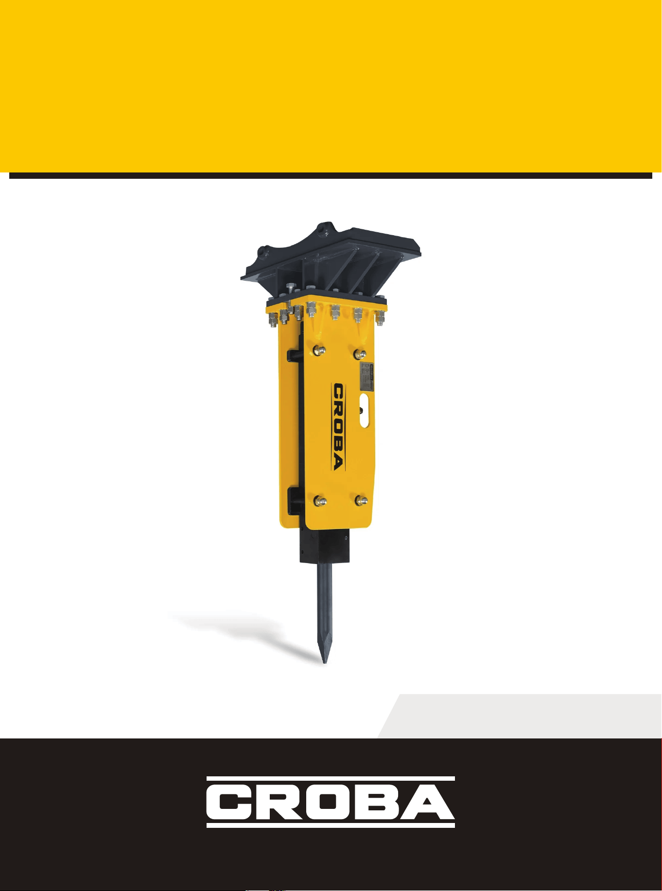
HYDRAULIC CONCRETE
BREAKER
BR300
Operator’s Manual
READ AND UNDERSTAND THE ENTIRE MANUAL BEFORE OPERATING MACHINE

TABLE OF CONTENTS
1
TABLE OF CONTENTS
SPECIFICATIONS 2
6
8
14
25
26
30
32
15
17
20
TRANSPORTATION
MAINTENANCE
TROUBLESHOOTING
SAFETY LABELS
GENERAL SAFETY
CONTENTS SUPPLIED
KNOW YOUR MACHINE
ASSEMBLY
OPERATING INSTRUCTIONS
PARTS DIAGRAM
SPECIFICATIONS
2
SPECIFICATIONS
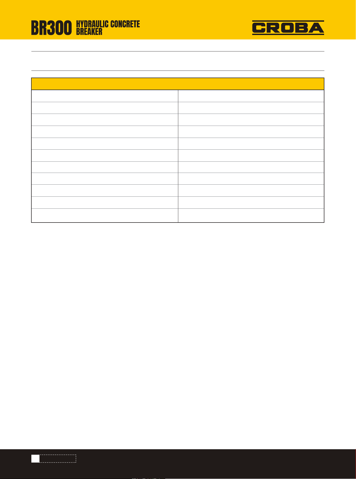
Specifications
Energy Class
Rod Dia.
Min Low
Operating Weight
Drive Pressure
Impact Frequency
Overall Size
Finish
Warranty
Packing Size
Weight (N.W./G.W.)
300ft-lbs
2 in
6.6 gal/min
375lbs
1750 psi
600-950 BPM
58x26x13 in
Powder Coating
1 Year
52x30x20 in
485/529 Ibs
3
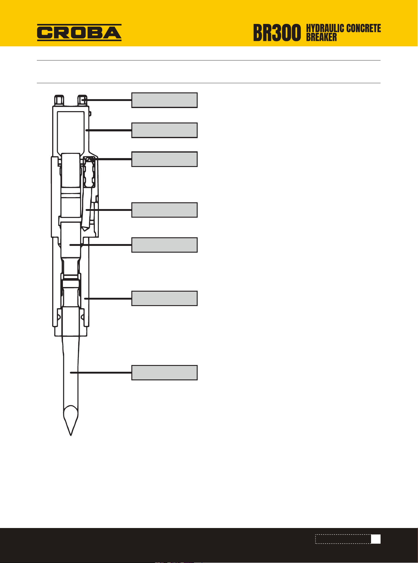
The four bolts connecting the upper steel-body, breaker
cylinder and lower steel-body together.
KNOW YOUR MACHINE
KNOW YOUR MACHINE
Thorough-Bolts
Thorough-Bolts
It is mainly used for storing nitrogen.
It controls piston to move up and down at certain
frequency.
As the heart of the breaker, it includes hydraulic circu-
lating system to control reciprocation of the piston.
It converts hydraulic kinetic energy into that of striking,
to strike the rod for breaking purpose.
It supports the oil cylinder and fixes the rod to prevent
oil cylinder from being damaged due to the counter
vibration force during striking.
The rod has received special strengthening treatment
to bear the friction from direct striking.
Upper Steel-Body
Upper Steel-Body
Reversing Valve
Reversing Valve
Oil Cylinder
Oil Cylinder
Piston
Piston
Lower Steel-Body
Lower Steel-Body
Steel-Rod
Steel-Rod
4
SAFETY
SAFETY
• Any equipment may have danger due to any careless or improper operation of breaking hammer.
• Read and understand the warning message of this manual to avoid any injury. Should you have any enquiry, please
consult your executive, Mechmaxx dealers, or A/S center.
• Safety is never anything to deal with warnings.
• You have to take into consideration the potential risks and how to avoid them when operating Mechmaxx breaking
hammer.
• Never operate a breaking hammer if you are not very sure about operation.
• Never start or operate a breaking hammer unless you are sure of a safe and reliable environment.
• Never make a reckless operation before you are pretty sure of how to operate a Mechmaxx breaking hammer.
Make a thorough check over the breaking hammer first.
a) Read this manual carefully prior to installation, operation and maintenance; should you have anything not clear,
please consult your executive, Mechmaxx dealers, or A/S center for detailed information.
b) Please keep this manual clean.
Warning
• Read carefully the following warning messages. These will make you aware of risk and how to stay
away from it.
• Injury could happen if proper prevention is not rendered.
Warning
• Read carefully the following safety messages. Neglect of the following safety practice will cause
injury of operator or related personnel, and lead to errors with equipment.
Manual
a)You must put on protective overalls to avoid any possible injury. Too loose clothes may be stuck into machine. E.g,
you have to wear helmet, safety goggles, earplugs, safety shoes, fitted overalls, gloves and mask.
b)Never use a necktie or a scarf. Wind up your long hair.
• Hoisting equipment.
• Injury may occur due to improper operation of a hoisting equipment.
• Make sure the hoisting equipment is in good condition.
• Make sure the hoisting equipment conforms to the local legal regulations and your operation requirements.
• Ensure that there is enough performance strength with the hoisting equipment and understand how to use the
hoisting equipment.
• Use of the equipment should follow local laws and regulations.
Overalls
Laws and Regulations
5
SAFETY
Caution
• Operate as required by safety regulations to avoid any potential risks.
• You may cause serious injury to yourself or others if you start operation you are not familiar with without due
practice.
• Practice on a piece of clean and flat ground, away from operating field.
• Make sure you are able to make safe operation for any new operation.
Practice
• A breaking hammer with defect may result in injury to you and others.Never operate or use a breaking hammer with
defect or any part missing.
• Follow the operation procedure of this manual strictly before use of this breaking hammer.
Status of Equipment
• Operation beyond the designed scope of breaking hammer is considered risky.
• Never operate a breaking hammer beyond the application scope.
• No refitting is allowed for the breaking hammer for purpose of improving performance, without permission.
Application Scope of Breaking Hammer
a)Failure to deliver correct message may lead to an accident.
b)Personnel should keep watch around where you are operating.d
c)Make sure your hand gesture can be understood while working with others.
d)Remember that loud noise often stays on the operating field. Never give an order by talking to each other.
Message delivering
a)Operating field is risky.
b)Make an inspection to the operating field prior to any operation.
c)Check if there is any pothole, anything not firmly fixed, or hidden stone, etc.
d)Check and take care of the public facilities nearby the operation (like cables, air or water tubes, etc)
Operating field
a)Fragments flying off during operation may hurt you.
b)You must wear safety goggles.
Crushed rocks and fragments
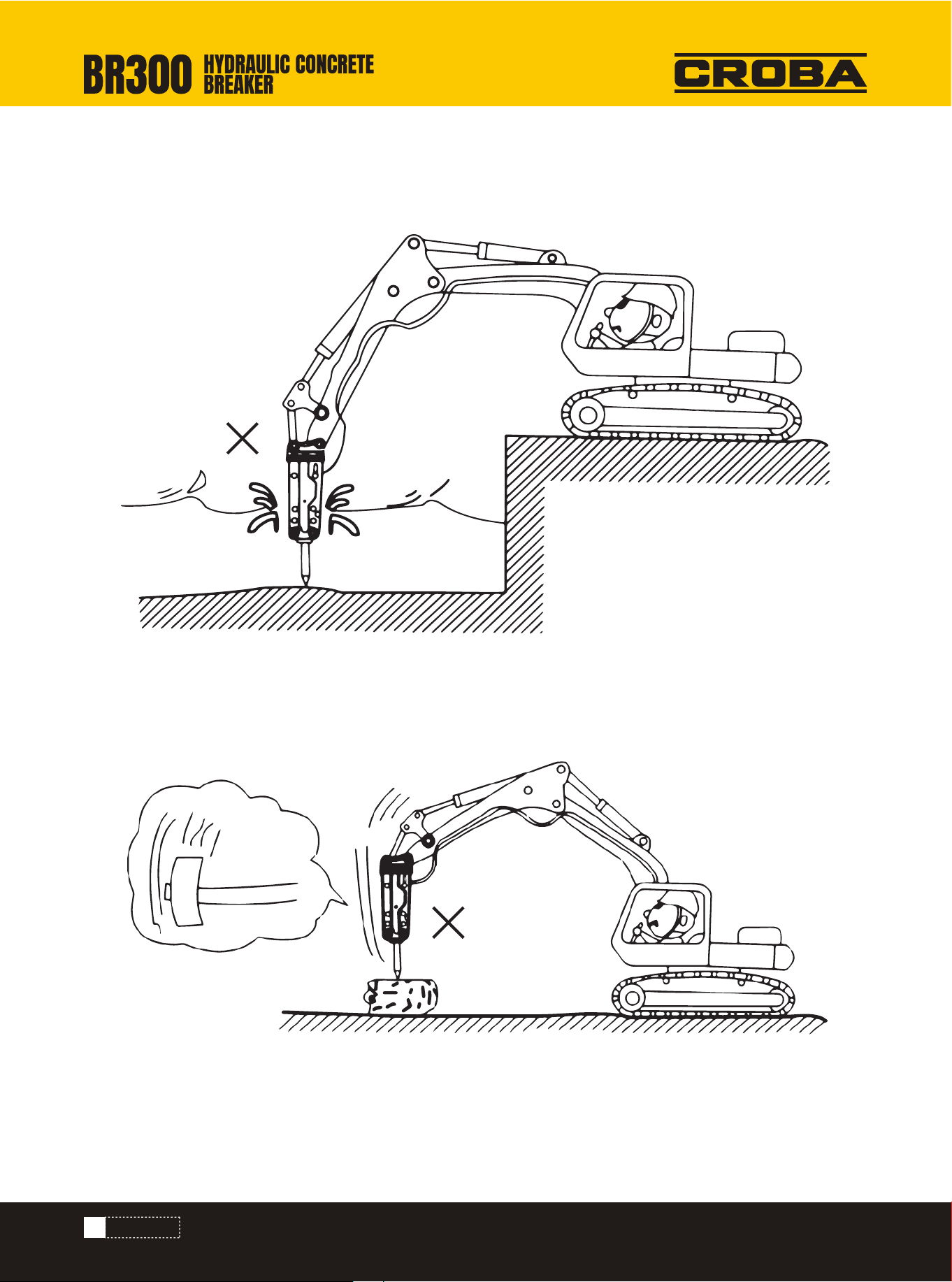
a)Collapse may happen due to operation at a hillock or ditch.
b)Never operate close to a hillock or ditch, which is risky and may cause a collapse.
Hillocks and ditches
a)It is very dangerous to operate in a public area without safety fence.
b)Set safety fence around breaking hammer to keep people from getting close whenoperating in a public area or
where operator cannot have a clear sight.
Safety fence
6
SAFETY
Caution
• Apply grease evenly to the breaking hammer when operating.
• Never operate the breaking hammer in water, which will cause malfunction.
• Take special care when lifting and delivering.
a)Never attempt any repairing or maintenance that you are clear of.
b)Never make any repairing or maintenance over breaking hammer without permission.Otherwise, injury or damage
may occur. Contact your MechMaxx center for consultation before any repairing or maintenance over a breaking
hammer.
Maintenance
a)Some redundant high-pressure enters the accumulator when breaking hammer is working.
b)The accumulator can compensate the pressure required for breaking hammer even if hydraulic loop is in lack of
pressure.
c)Never attempt to dismantle accumulator before pressure is discharged. Otherwise, serious injury/damage may
occur.
d)Never attempt to dismantle accumulator with pressure.
Accumulator
a)The pressure flowing in the hydraulic oil way is very risky.
b)Turn off engine and discharge the remaining pressure inside the tube controlling operation before dismantling and
connecting hydraulic oil tubes.
c)People concerned should keep away from hydraulic oil tubes while breaking hammer is working
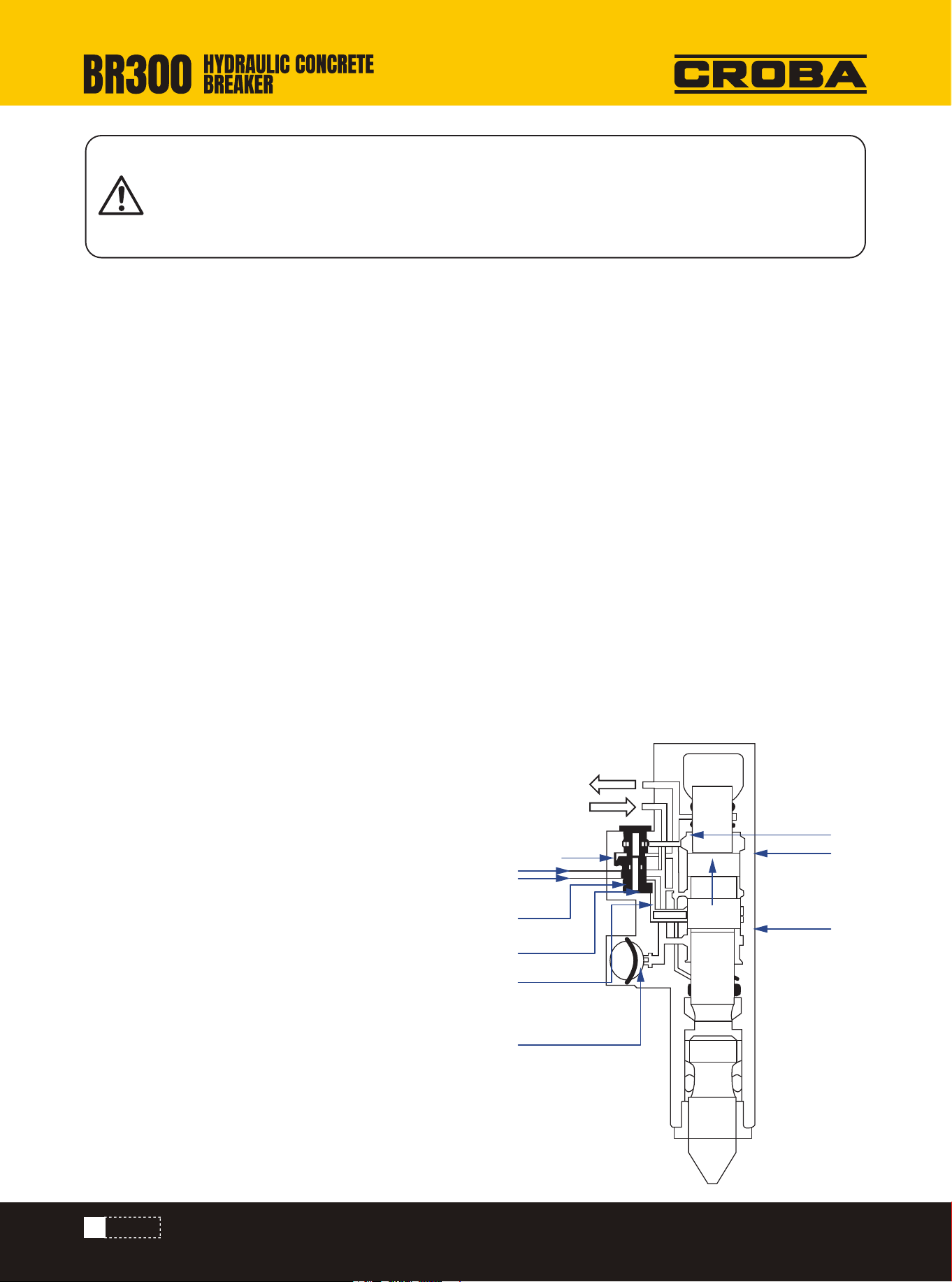
Pressure A1 in the back cavity of piston is greater than that
of A2 in the front cavity; high-pressure oil always acts on
cavity A2. When oil pressure is working, the pressure of A1
goes drops from a higher level, and vice versa. Piston C2 is
therefore reciprocating. Similarly, high-pressure cavity A3 of
valve <A4, then high-pressure oil continuously acts on cavity
A3 and A4. Valve then moves to A4 and vice versa. The shift
of valve C4 also changes pressure of piston's back cavity B1
from high-pressure side to the low one and vice versa. Valve
C4 and piston C2 are having the same reciprocation.
Besides, the upper body is filled with nitrogen. When piston
moves backward, the nitrogen is compressed and air-energy
is stored. When piston is working, the air energy is then
converted into kinetic energy of piston.
Hydraulic system
<Relation between pressure actions>
Operating Principle
OUT
IN
C4
B1
A2
A1
C2
A3
A4
V4
V1
B3
B4
7
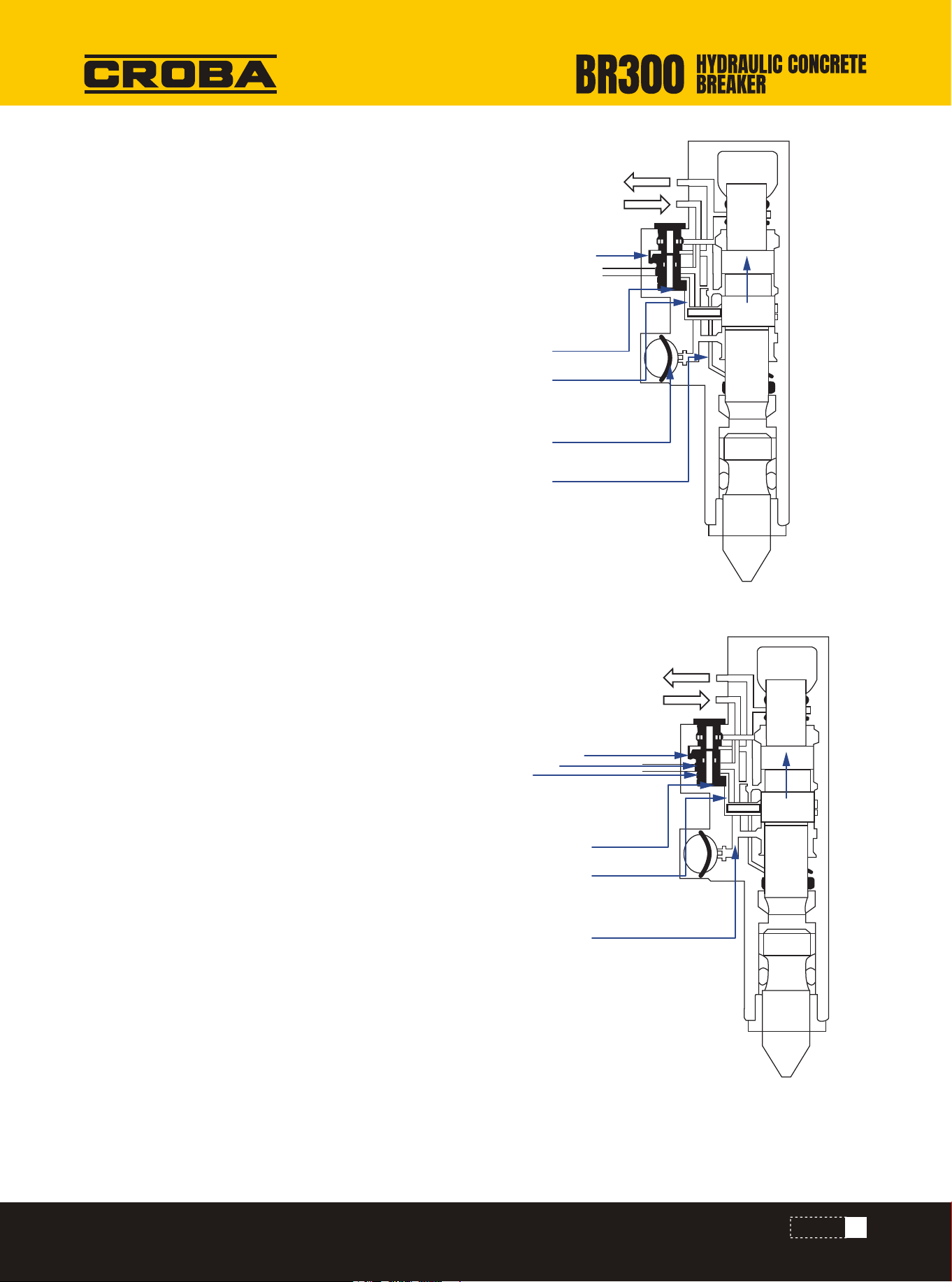
When high-pressure oil flows into the intake "IN" of hydraulic
braking hammer, high-pressure oil will act on the front cavity
A2 of piston. High-pressure cavity V1 will then control the
valve. And when back-cavity B1 is connected through "OUT"
oil outlet and changed to low-pressure, high-pressure oil will
act on the front cavity A2 of piston, and piston C2 will move
backward. Meanwhile, the nitrogen in the upper body will
then be compressed into air pressure and stored into accu-
mulator C5.
<Piston startup>
When piston moves backward, back-cavity B1 is connected
with valve shift-port B3, high-pressure oil will act on the
change-cavity V4 of the valve to effect changes over the
valve. In the mean time, back-cavity B1 is disconnected from
low-pressure cavity V3 and is connected with high-pressure
cavity of valve V1. The pressure inside back-cavity B1 will
then be increased.
<Valve pressure filling>
OUT
IN
C4
C2
V1
B3
C5
B4
OUT
IN
B3
V4
V3
C2
V1
B2
A2
SAFETY
8
Precautions
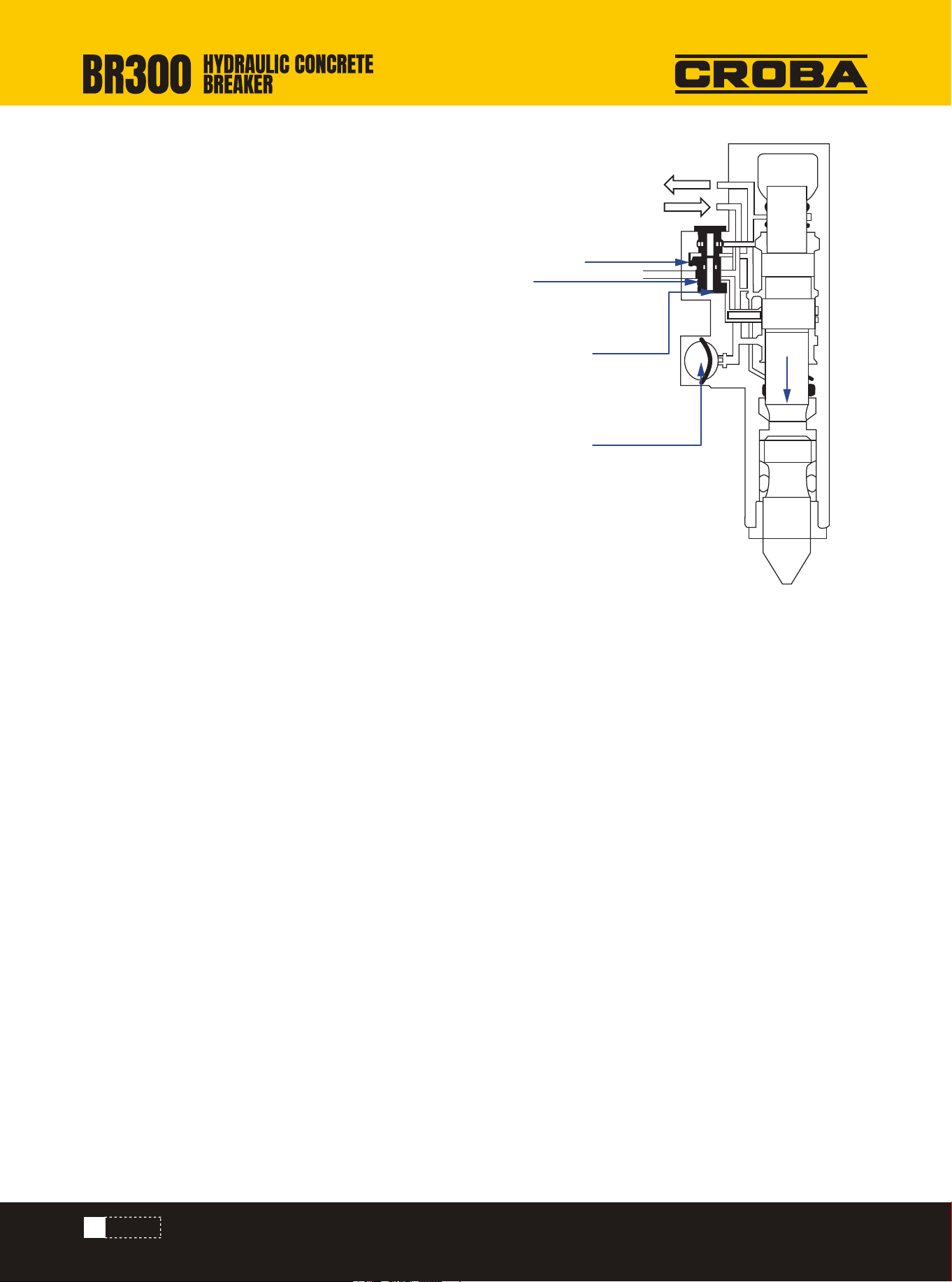
When piston C2 reaches the dead point at the top, the
high-pressure oil from high-pressure cavity of valve V1 will
continuously act on the back-cavity B1, which will make a
continuous striking of piston; meanwhile, the energy stored
inside accumulator C5 will then be converted into the energy
of compressed air and enter the upper body. The effect of
high-pressure oil of high-pressure cavity V1 and change-cav-
ity V4 of the valve leads to the efficient turn-on of the valve.
• Protective shield against fragments should be installed in front of the driver's cab to prevent from any injury/dam-
age due to shivers during operation.
• All personnel on site, including excavator driver, must wear earplugs and face-mask during the course of operation.
• The driver should operate the breaking hammer by sitting on the seat. Breaking hammer can only be used when
both excavator and breaking hammer are in normal state.
• In case anyone enters the dangerous area of operation, stop the breaking hammer immediately; compared with
excavator, the breaking hammer in operation may cause more possible injury to people with the fragments flying
off.
• Operate excavator as required by manufacturer's safe operation regulations when operating with a breaking
hammer. Ensure to use a well-installed and properly adjusted breaking hammer.
• Never operate a breaking hammer when reaction is shown due to drinking alcohol or taking drugs.
• Ensure stable working conditions and lower operating device when conducting maintenance and inspection/repair-
ing.
<Continuous striking of piston>
OUT
IN
V4
C4
C2
V1
C5
SAFETY
9
OPERATION
OPERATION
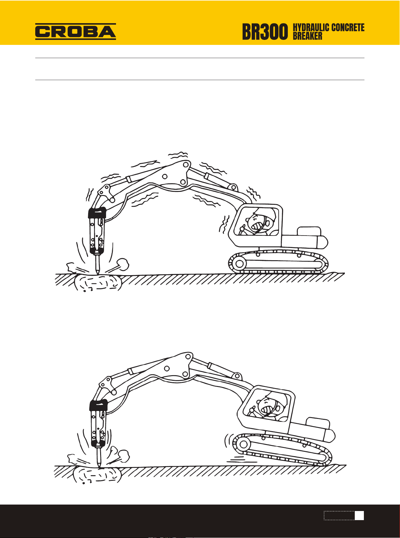
FIG 3-2
FIG 3-1
Proper Operation Mode
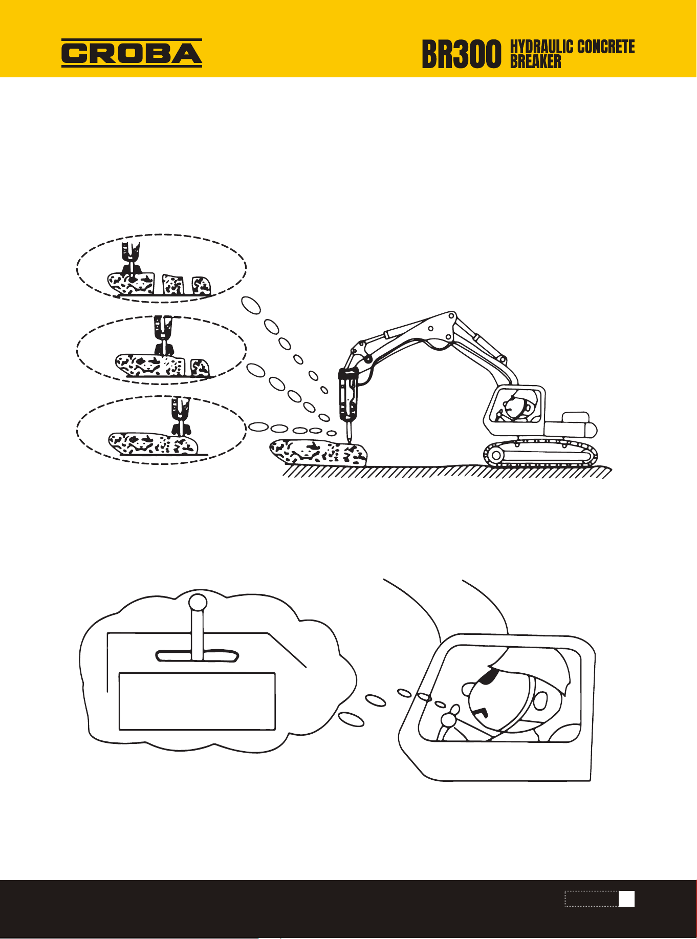
1) Appropriate Breakdown Power
To effectively break down, breaking hammer should be used with appropriate breakdown strength. If the breakdown
strength is not strong enough, the hammering energy of piston will not effectively crush stones; the counter force of
this kind of hammering will be transferred to the hammer itself, the large and small arms of excavator, and will there-
fore damage these components.
On the other hand, while lifting the large excavator arm, if using excessive breakdown strength during crushing oper-
ation, the machines may suddenly tilt during crushing stones, the fierce crash of hammer to the stones will cause
severe damage to the hammer; if crushing under these circumstances, the vibration will spread to the caterpillar
track of excavator, so in such a situation operation should be avoided in order to protect the track.
10
OPERATION
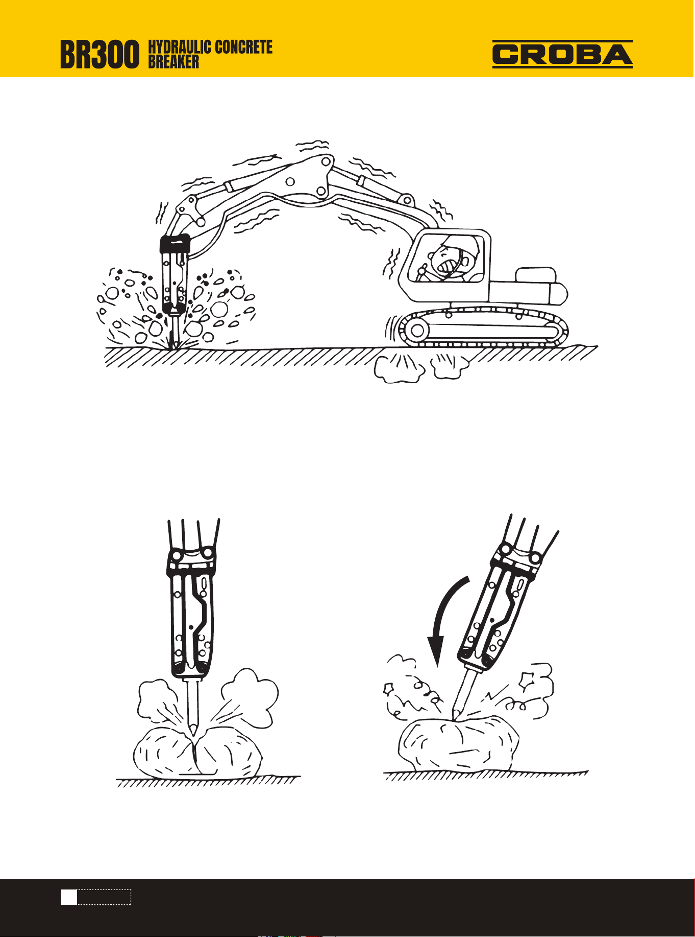
FIG 3-4
FIG 3-3
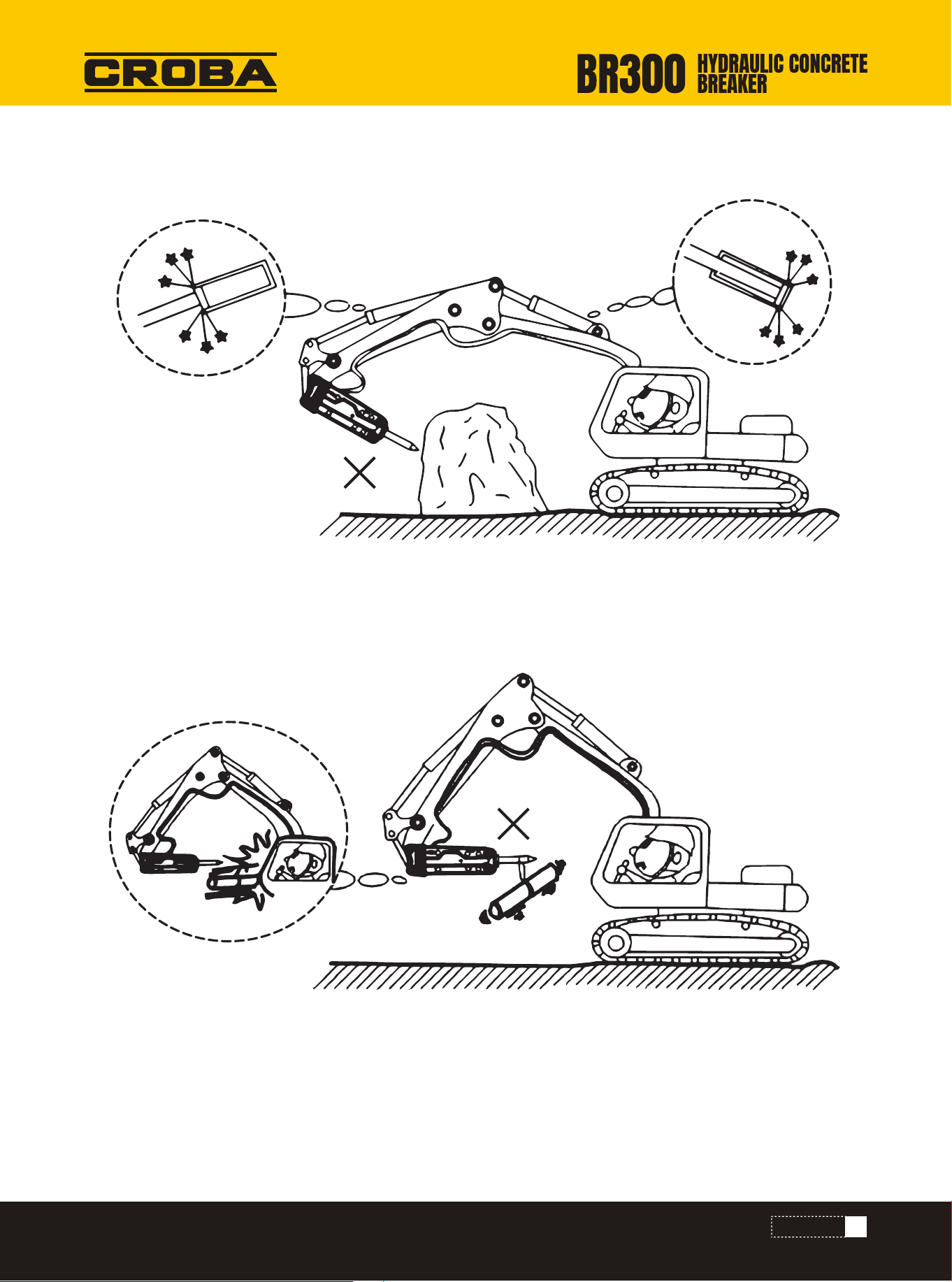
2) Breakdown Direction
Breakdown direction should be in a straight line with the steel-rod. When the steel-rod crushes rocks, it should main-
tain the vertical direction to carry on the work as much as possible. If hammering direction inclines, then during
hammering operation, the steel-rod may slide, causing the steel-rod and piston broken or to get stuck. Therefore
while carrying on crushing operation, breakdown points should be carefully chosen, in order to ensure the stable
hammering.
Therefore during striking period, attention must be paid to the breakdown strength of breaking hammer at all times.
Do not operate if breakdown strength is not appropriate.
11
OPERATION
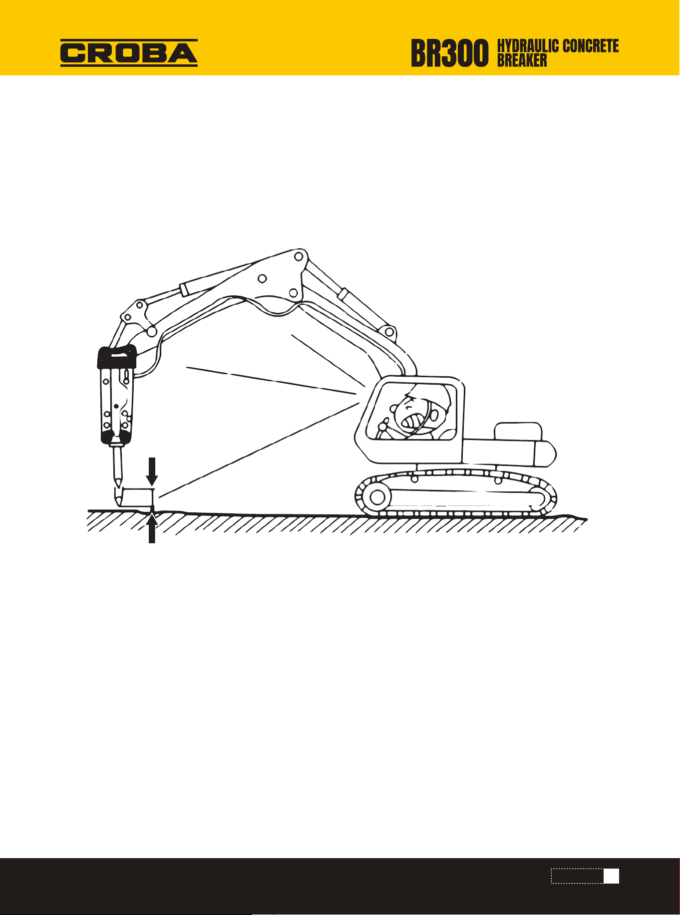
FIG 3-5
3) Precautionary Measures During Operation
During breaking hammer operation period, operators should pay attention to the followings:
a)Operation should be stopped if hoses are in severe vibration
Check if the vibration of high and low pressure hoses of breaking hammer is too drastic. If yes, it might be because
the accumulator fails, you should immediately contact your local service office authorized by us to obtain repair
service. You should further inspect if there is oil leaking at the hose joints, if so, re-tighten the joints. As illustrated
by Figure 3-5, visual check if there is some allowance of the steel-rod during operation; if there is no allowance, it
must be stuck in the lower body. Dismantle the lower body, check if the part needs repairing or the failed part needs
replacing.
b)Stop operations (to avoid excessive empty strikes)
Stop hammering immediately once stones are crushed. If continuing the empty strikes, the accumulator might be
damaged, bolts will be loosened or broken, even the excavator will be adversely affected. When using hammer with
improper breakdown strength or using steel-rod as a pry bar, it will cause empty strikes. (The crushing sound will
change when striking empty)
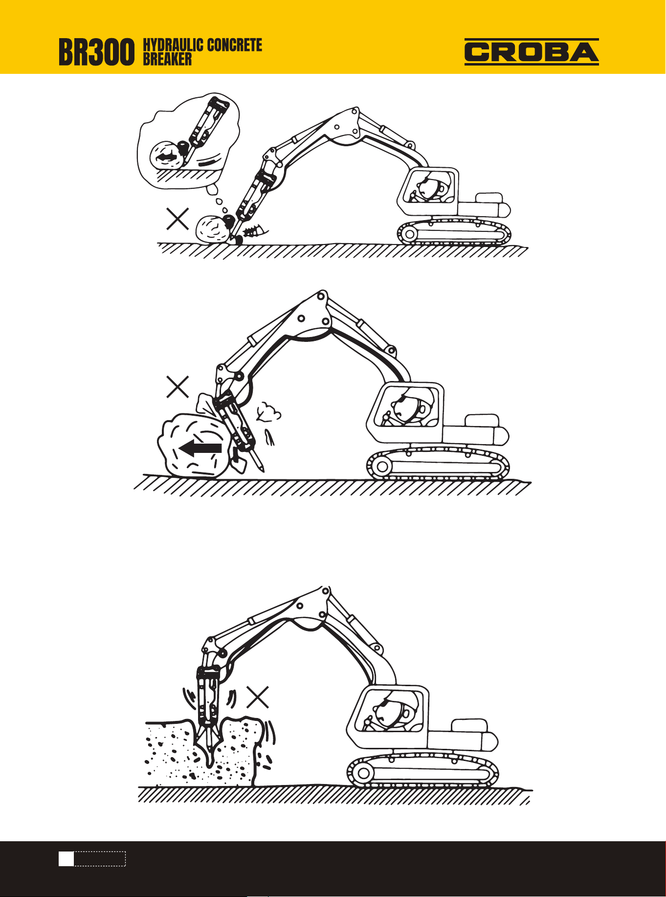
C)Breaking hammer can not be used to remove stones
As shown in Figure 3-6 and 3-7, do not use the end of steel-rod or the side of the support to roll or push stones.
Because at that moment, oil pressure comes from large and small arms, bucket, swinging or sliding operations of
excavator, therefore the large and small arms will be damaged. In the meantime, the bolts of breaking hammer may
be broken, support may be damaged, and steel-rod may be broken or scratched; one should avoid using breaking
hammer to move stones. In particular, excavator should never move when the steel-rod is inserted into the stones.
12
OPERATION
FIG 3-6
FIG 3-7
FIG 3-8
d)Never use steel-rod as a pry bar
As illustrated by the figure, if using steel-rod as a pry bar during crushing the stones, the bolts and steel-rod may
break.
13
e)Do not strike continuously for more than one minute
When striking hard rocks, do not continue crushing the same place for over one minute, then change to another
place. Prolonged operation will increase the oil temperature, which would lead to accumulator damage and exces-
sive wearing of steel-rod.
f)For long and hard large stones, start crushing it from the end.
For those longer stones, one may start the crushing from cracks or their ends, which is relatively easy to break
stones.
g)Breaking hammer should be operated at appropriate engine speed
During crushing operation, the engine speed should meet the required value; the engine speed over the operation
requirement will not increase breakdown strength, but the raised oil temperature will lead to damaging equipment.
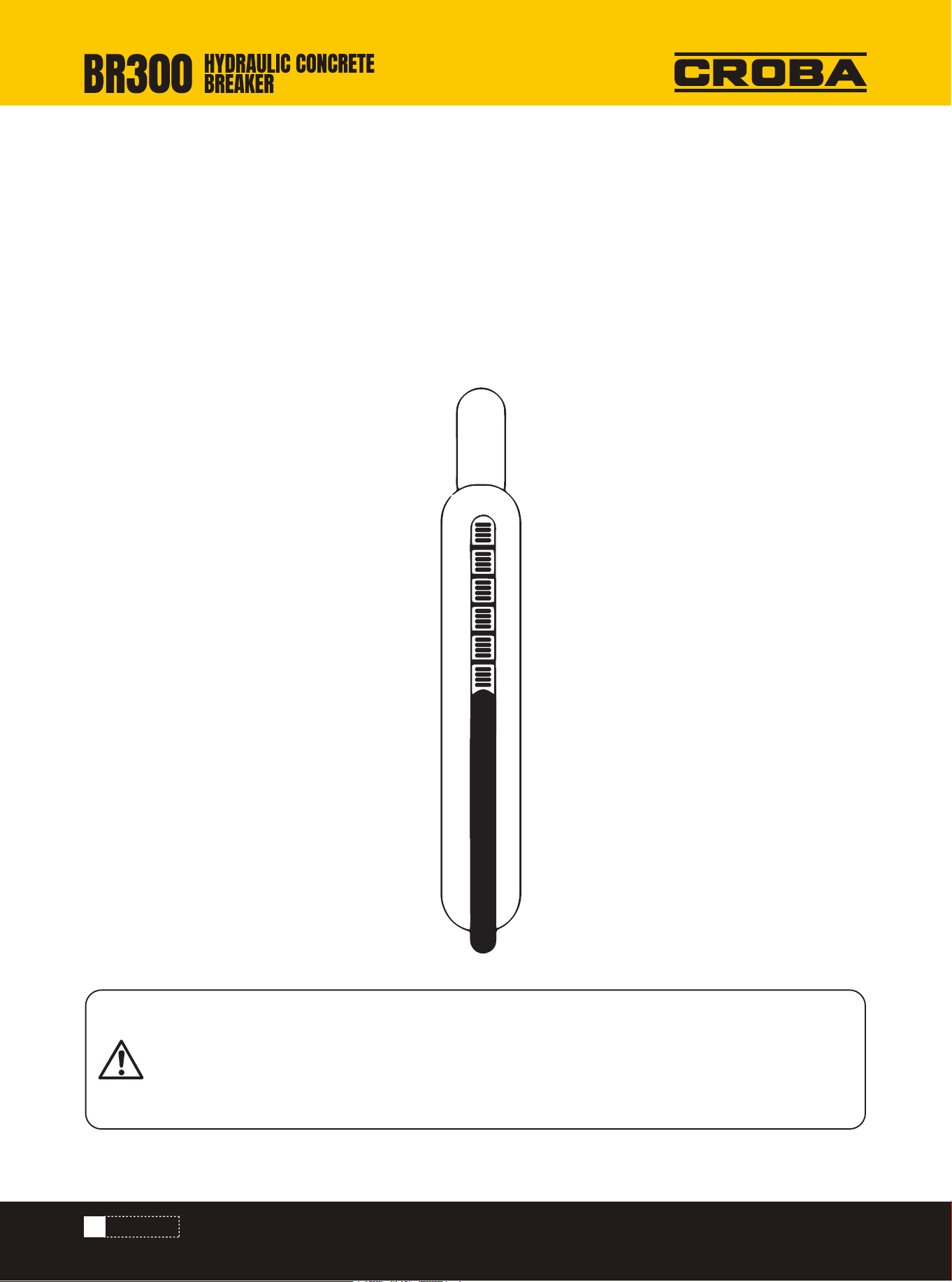
THROTTLE LEVER LIMIT
POSITION DURING HYDRAU-
LIC BREAKER OPERATION
FIG 3-9
FIG 3-10
OPERATION
14
h)Breaking hammer could not work in water or mud
Do not use breaking hammer in water or mud; Otherwise, the piston or similar components may rust and lead to
permanent damage. If in or under water operation is required, order special underwater breaking hammer.
I)Do not allow breaking hammer to fall directly to crush stones.
If the breaking hammer falls directly to crush stones, hammer or excavator will bear too much power, which will
easily damage excavator parts.
FIG 3-11
FIG 3-12
OPERATION
15
j)When oil cylinder rod on the excavator's large arm has its maximum stroke, do not start striking operation.
When oil cylinder rod has its maximum stroke (rod is fully extended or retracted), if Conducting crushing operation,
it will damage oil cylinders and various components of excavator.
k) Do not use breaking hammer to hang objects
Do not tie ropes to the breaking hammer, supports and steel-rod to hang objects; this will easily damage the breaking
hammer, supports and steel-rod, and this is also a very dangerous operation.
FIG 3-13
FIG 3-14
OPERATION
16
Important Notice
i)It is worth mentioning that in winter, the engine should be started for 5-20 minutes to warm up before operating the
breaking hammer.
The engine should be preheated according to the maintenance instructions of excavator; if without engine preheat-
ing and operating crushing at low temperature, it could easily damage various parts of breaking hammer, such as
piston and seals, etc.
Operating temperature should be between-20℃~80℃ (-40°F~176°F)
When temperature drops below-20℃(-40°F), preheat the breaking hammer and steel-rod before hammer starts oper-
ations, in order to avoid damage to accumulator, rubber cup and steel-rod; breaking hammer must maintain a normal
operating temperature during operation.
When the temperature is below-20℃, and hydraulic oil is in the state of low temperature, hydraulic
breaking hammer should not be put into use; otherwise, it will lead to hammer's oil seal broken and the
high pressure of accumulator will tear up the rubber cup. Pay attention to relevant provisions of exca-
vator manufacturers.
Operating Temperature
+80°C +176°F
-20°C -4°F
OPERATION
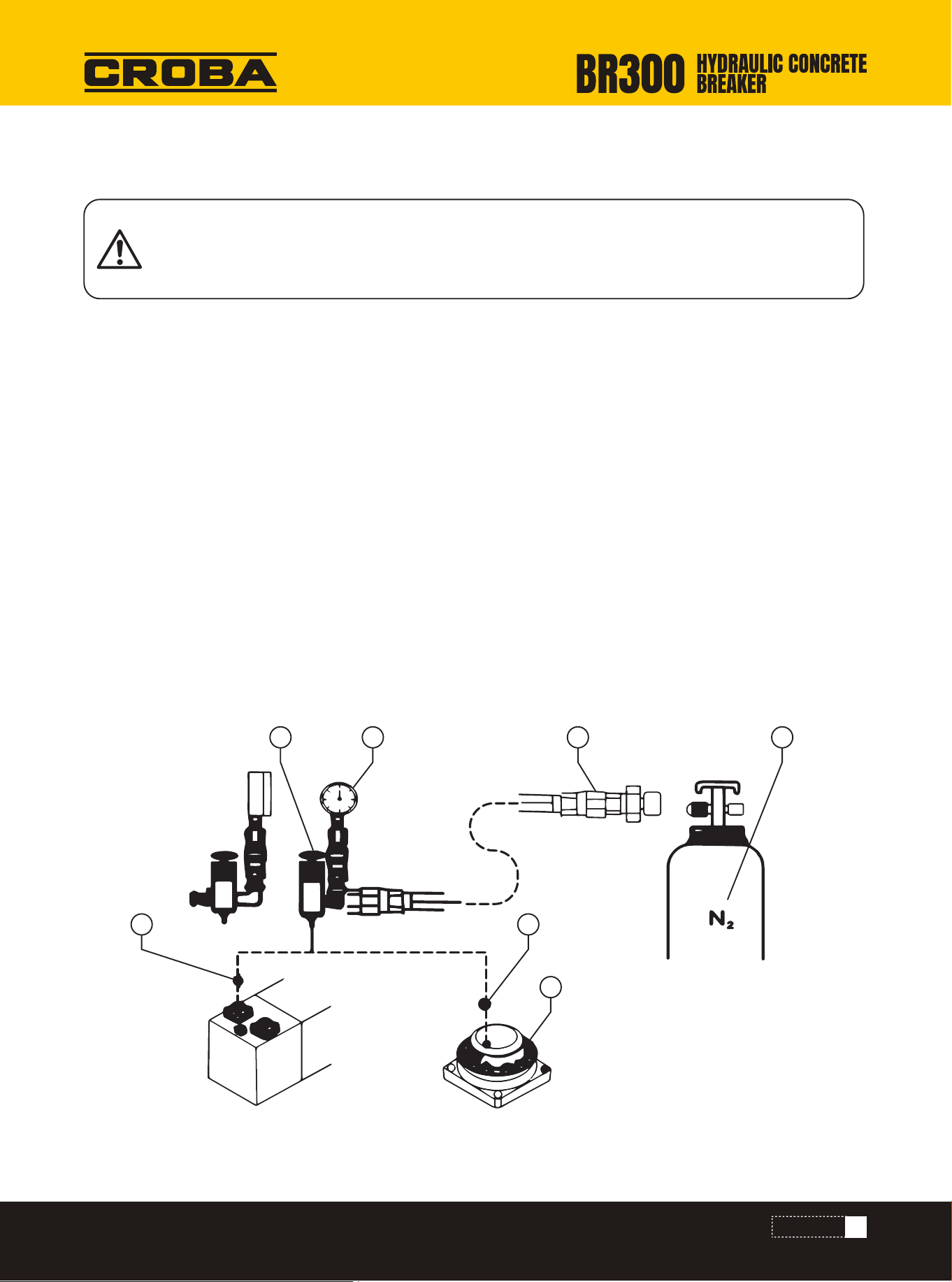
17
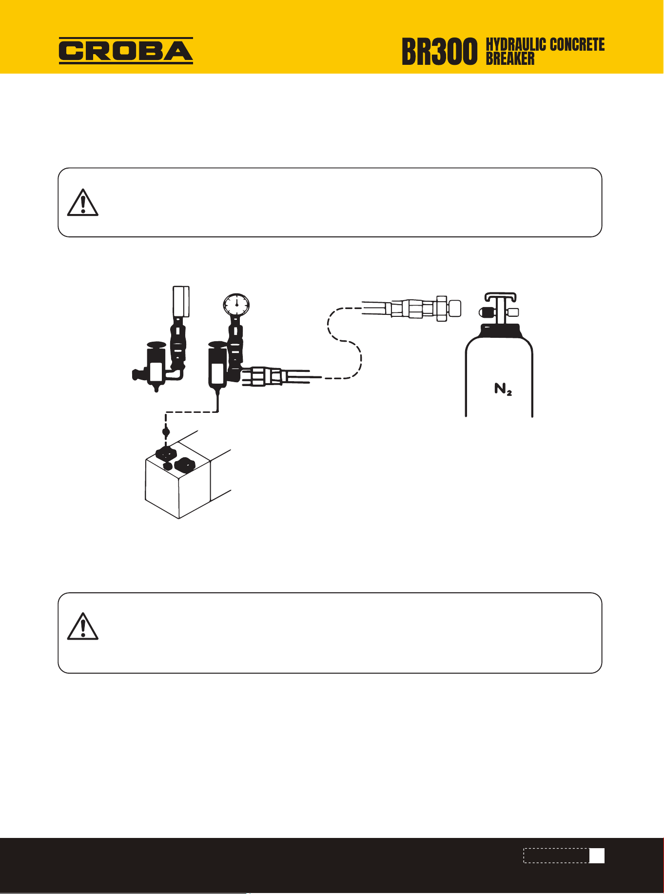
1.Connect the hose (5) on the nitrogen (N2) steel cylinder (6)
2. Loosen the charging valve cap (1)
3. Accumulator, connect the upper body to the charging equipment
4. Tighten the triple valve switch (2) on the charging equipment
5. Rotate the regulator switch (3), and observe the charging pressure value displayed on the pressure gauge (4)
6. When the nitrogen (N2) pressure is less than or close to the stipulated value, please slowly rotate the regulator
switch. (Warning: if there is no overflow valve in the charging equipment, the overflow air pressure is very danger-
ous.)
7. Tighten the triple valve on the charging equipment, the accumulator pressure value is 60 bar, and the upper body
pressure value is 6 bar.
8. Tighten the nitrogen (N2) charging switch.
9. Adjust accumulator and upper body to appropriate pressure value.
10. Release the pressure inside hoses and charging equipment.
11. Please check if there is any gas leak, check if there is oil leak from charging valve.
12. Tighten the charging valve cap (1).
13. Give appropriate pressure value (bar).
Warning
The accumulator can only be charged with nitrogen (N2). Charging other gas(es) is extremely danger-
ous, and the accumulator, the upper body can possibly explode.
How to Charge Nitrogen (N2)
Upper Body Accumulator
OPERATION
1 1
3
1 4 5 6
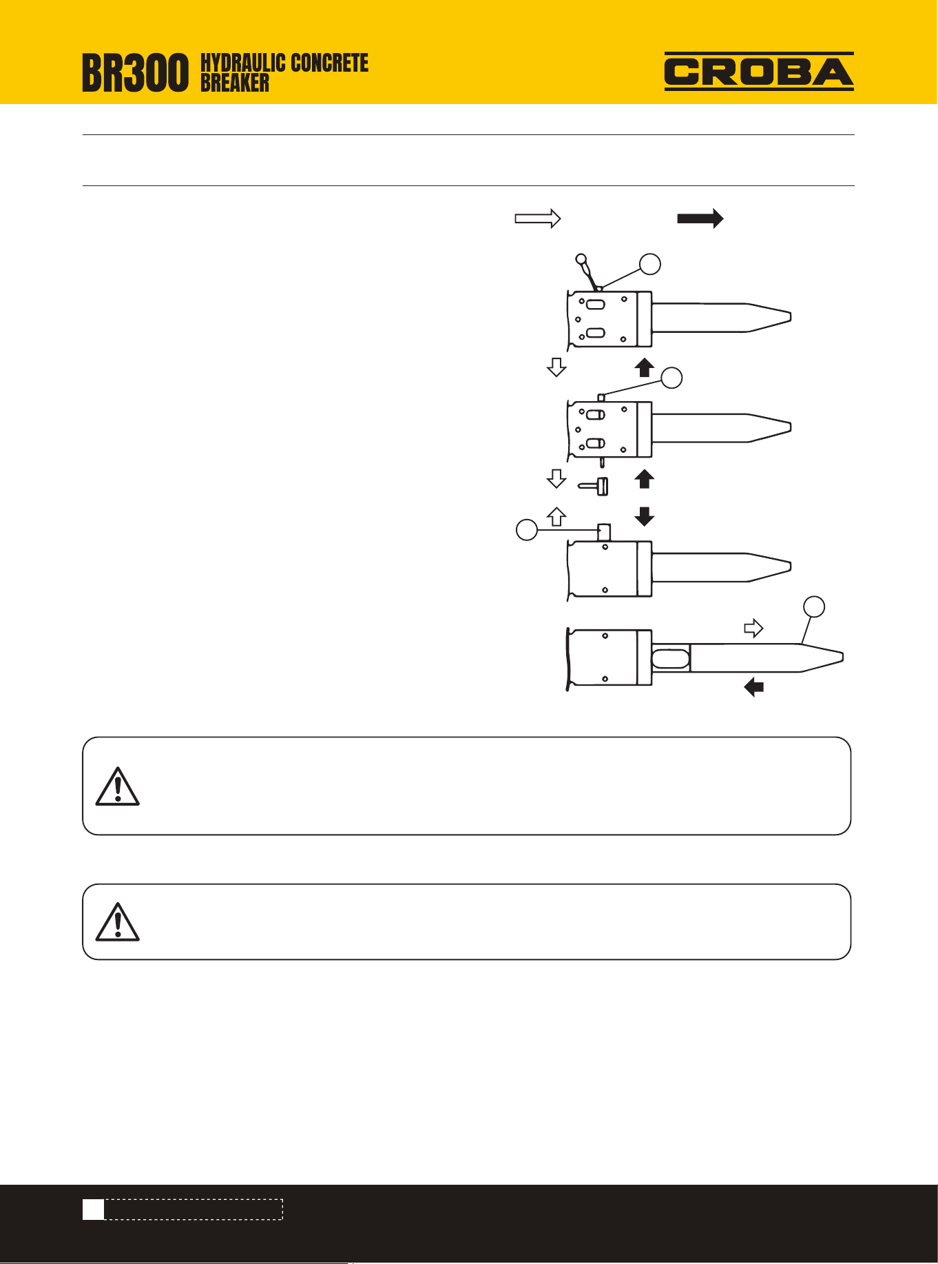
18
DISMANTLING & REASSEMBLING
DISMANTLING & REASSEMBLING
1) Dismantling
a)Place breaking hammer at a flat working field
b)Please confirm the gearbox of excavator is in neutral and
has fully stopped.
c)Turn off the engine.
d)Use screwdriver to dismantle the rubber plug screw a
e)Dismantle lock pin b of steel-rod
f)Dismantle flat pin c of steel-rod
g)Dismantle steel-rod d
2) Reassembling
a)Clean and lubricate steel-rod and flat pin
b)Install steel-rod d, flat pin c and lock pin b of steel-rod
c)Check if flat pin c is locked tightly by lock pin b.Screw on
rubber plug screw a
1) Upper body nitrogen (N2) discharging
• Completely discharge the nitrogen (N2) in upper body. Otherwise it might explode if bolts are loosened.
• Observe the following charging steps.
2) Upper body nitrogen (N2) charging
• Install the charging joints of charging valve, connect N2 steel cylinder and charge the upper body.
• Connect charging valve cap to the upper body
Warning
Do not attempt to disassemble or assemble the equipment until you have finished reading this chap-
ter.
Warning
Never attempt to dismantle or assembly upper body.
Dismantling and Reassembling of Steel-Rod
Charging and Discharging of Nitrogen (N2) for Upper Body
Dismantling Reassembling
FIG 4-1
a
b
c
d
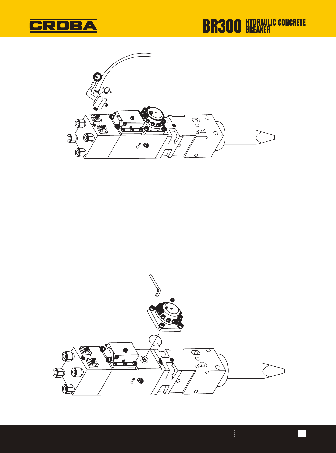
19
DISMANTLING & REASSEMBLING
1) Dismantling
• First, dismantle accumulator cap.
• Discharge nitrogen (N2).
• Place the accumulator ass'y flat as Figure 4-3, then use an inner hexagon spanner to dismantle them.
• Dismantle the O-ring.
2) Reassembling
• Fasten the O-ring.
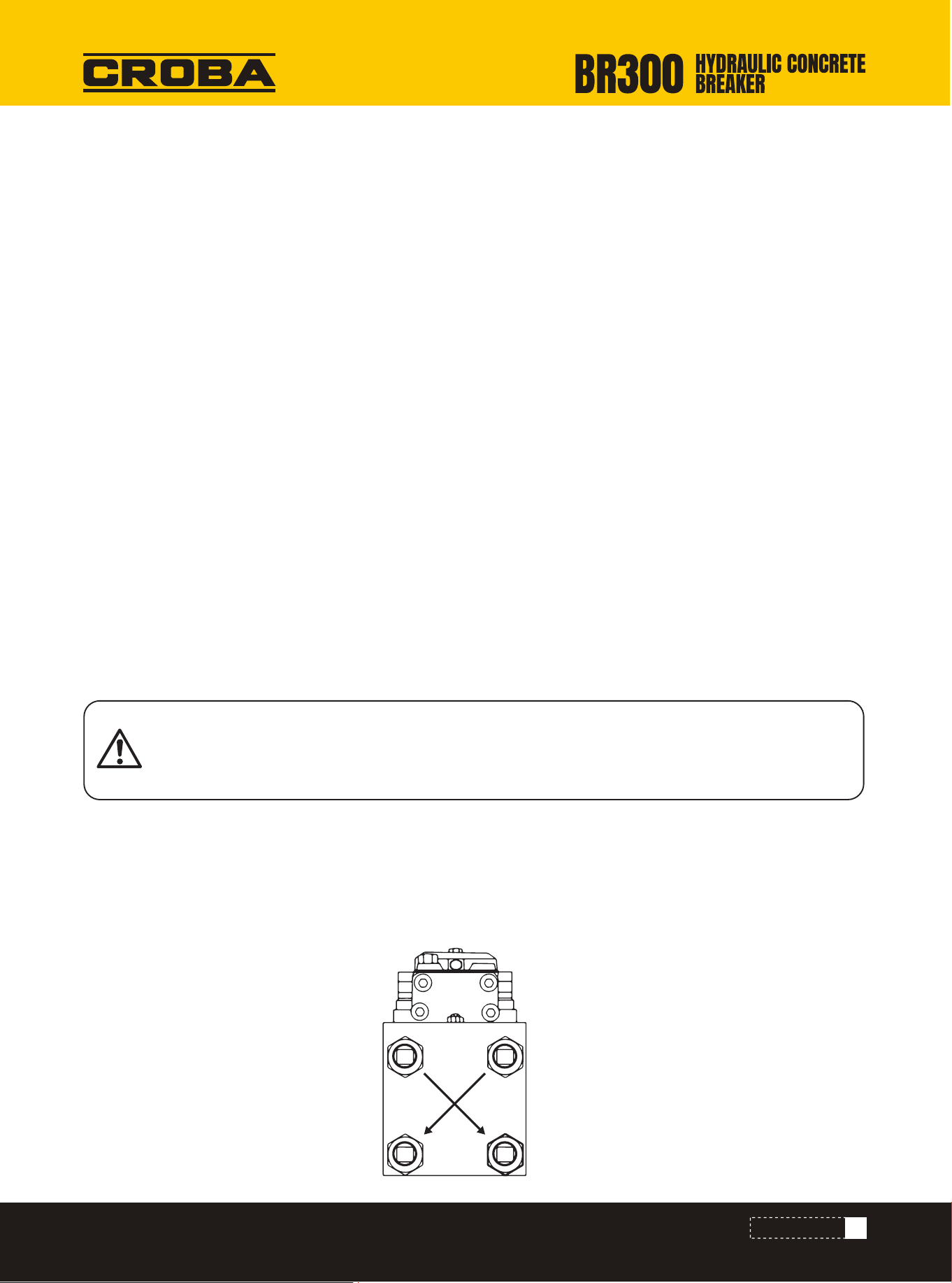
• Use torque spanner with the torque strength of 600N.M to screw up all the inner hexagon bolts in diagonal direc-
tion.
Dismantling and Reassembling of Accumulator Ass'y
FIG 4-2
FIG 4-3
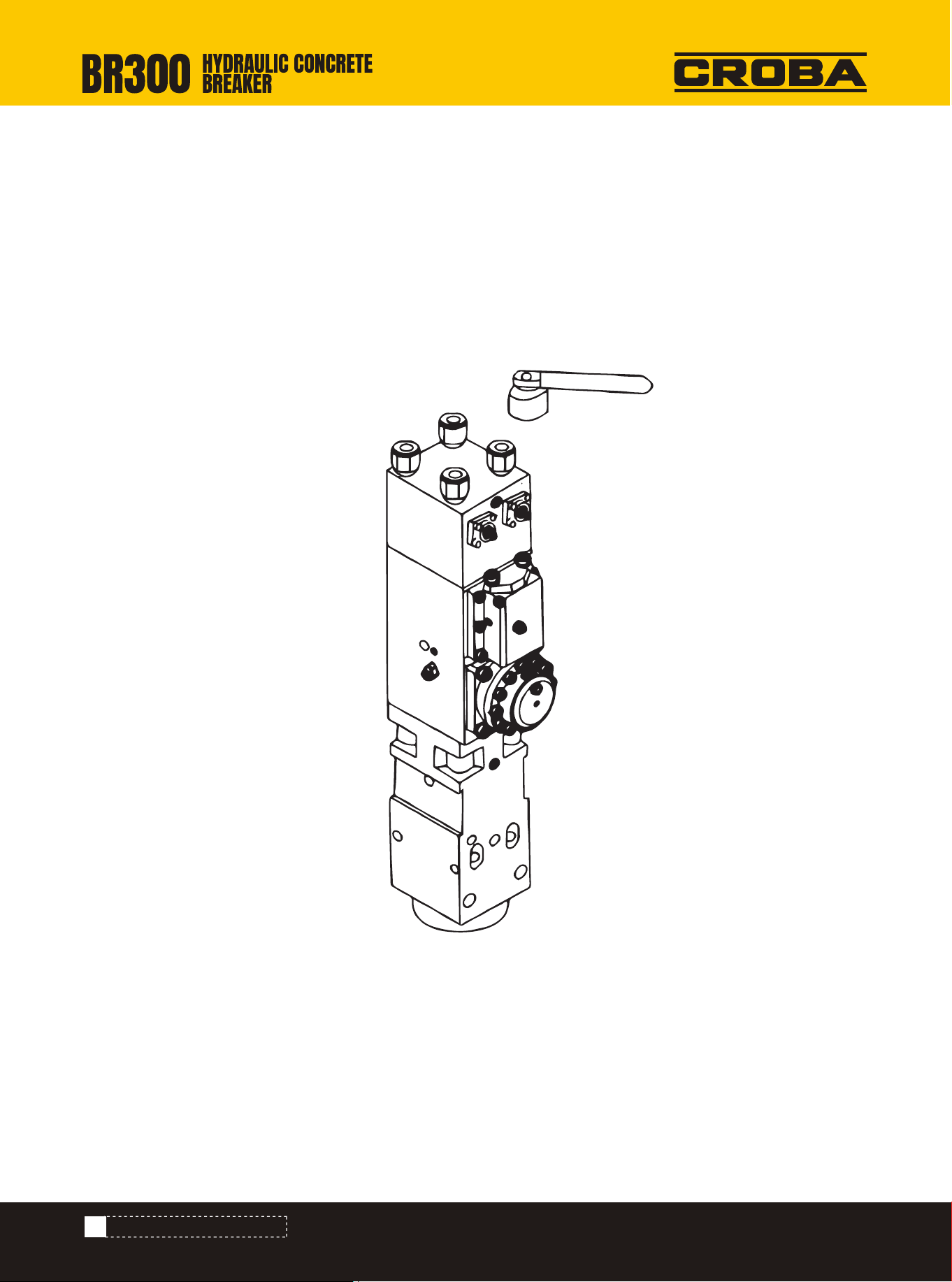
20
DISMANTLING & REASSEMBLING
1) Loosening
• To loosen the nuts of thorough bolts requires a strong spanner or percussion wrench. But once they get loosened,
we can use hands to screw them off.
2) Screwing up
• First, clean thorough bolts and their contact surface.
• Grease the thorough bolts.
• When the thorough bolts are screwed halfway, use the same degree of torque strength to screw them up in diago-
nal direction. Screwing up the thorough bolts requires torque wrench.
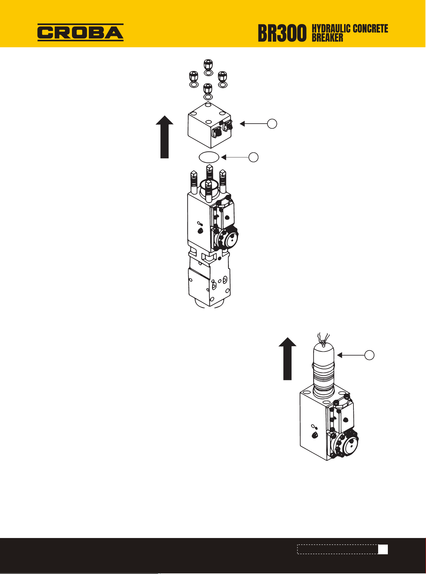
1) Dismantling
• Require crane/overhead trolley conveyor to dismantle the upper body-a
• Dig out O-ring-b
2) Assembling
• After greasing the O-ring of upper body, place it on the top of the oil cylinder, it should perfectly fit into b.
• Connecting the top of upper body and oil cylinder requires crane/overhead trolley conveyor a.
Loosening and Tightening of Thorough-Bolts
Dismantling and Reassembling of Upper-Body
FIG 4-4
21
DISMANTLING & REASSEMBLING
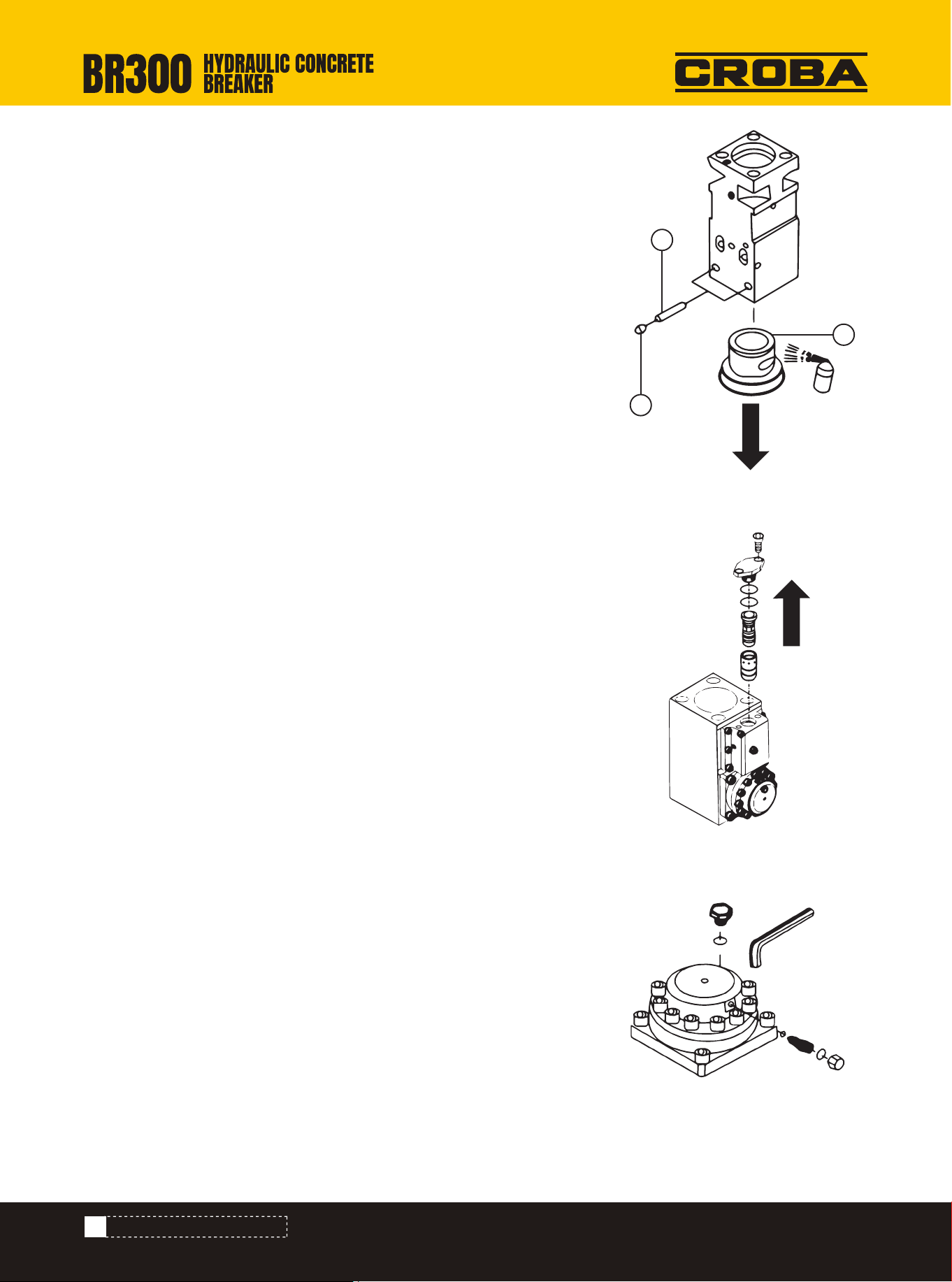
1) Piston and seal seat dismantling
• Use crane to vertically lift piston C. Choose position according to the
conditions of working room.
• Vertically place the dismantled piston, use rubber hammer to slowly
pound the seal seat from the bottom of the piston to the top, then
dismantle it.
2) Piston and Seal Seat Reassembling
• Use crane/ overhead trolley conveyor to put piston C slowly into the oil
cylinder
• Plastic or rubber hammer should be used to pound the seal seat to enter
it into the rubber groove and completely inserted inside.
Dismantling and Reassembling of Piston/Seal-Seat
FIG 4-5
FIG 4-6
A
B
C
22
DISMANTLING & REASSEMBLING
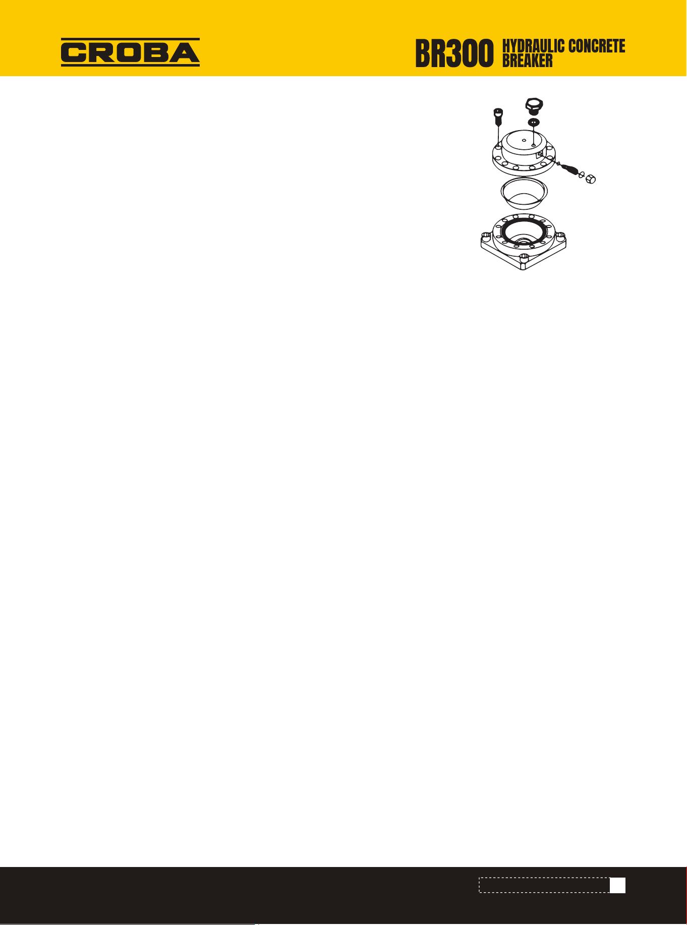
1) Dismantling
• Dismantle rubber plug screw D
• Dismantle lock pin E of under-bushing
• Dismantle under-bushing F of steel-rod
• If the under-bushing is hard to dismantle, please heat the bottom of the
lower body
• Check the degree of wearing of steel-rod and under-bushing.
2) Reassembling
• Clean all parts
• Spray supramoly over the contact surface between steel-rod
under-bushing and the lower body
• Install steel-rod under-bushing F
• Install lock pin E of lower-body
• Install rubber plug screw D
1) Dismantling
• Dismantle bolt (M24)
• Dismantle the seal cap of control valve
• Dismantle the O-ring of seal cap
• Dismantle valve plug and valve
2) Reassembling
• Brush off the hydraulic oil on seal cap of control valve and insert it into
the control valve.
• Grease the O-ring and place it in the seal cap.
• Use inner hexagon wrench to screw up the bolt of control valve cap.
Dismantling and Reassembling of Steel-Rod Under-Bushing
Dismantling and Reassembling of Control Valve Ass'y
1) Dismantling the accumulator
• When dismantling the accumulator, nitrogen (N2) should be completely
released before taking the next step.
• Fix the accumulator to the working table, then dismantle the charging
valve, dismantle the charging valve with a sleeve ratchet-handle wrench
of counter back-turning.
Dismantling and Reassembling of Accumulator Rubber-Cup
FIG 4-7
FIG 4-8
FIG 4-9
F
E
D
23
DISMANTLING & REASSEMBLING
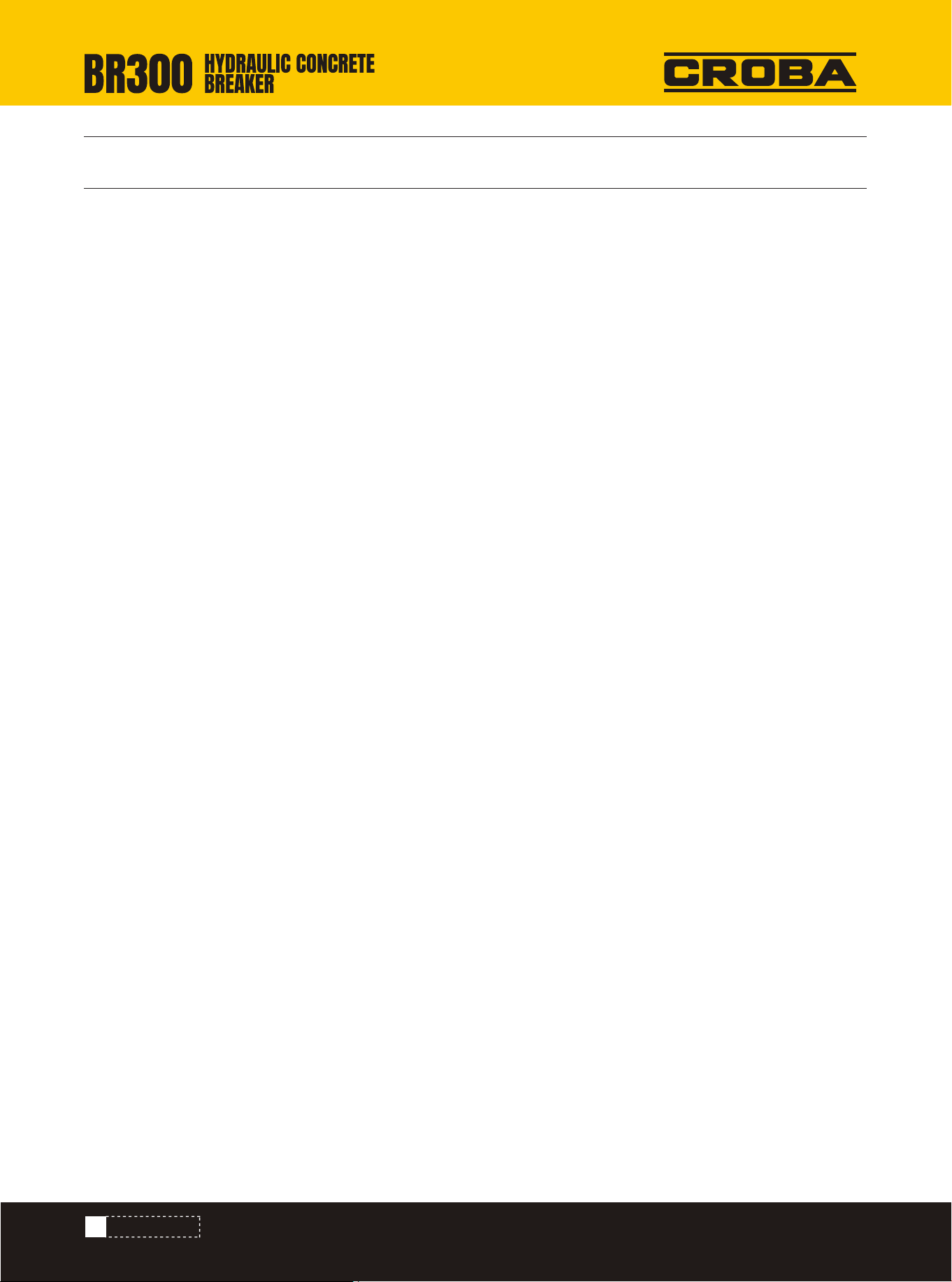
2) Rubber cup reassembling
• Place accumulator body on the working table, put it into the rubber cup,
fix it closely to the edge of accumulator with fingers.
• Assembly accumulator seal cap, put the cap on the top of rubber cup,
insert it and fix the bolts, use inner hexagon wrench to screw these bolts.
Use torque wrench with the exact same torque strength to screw up the
bolts in diagonal direction.
FIG 4-10
24
INSTALLATION
INSTALLATION
-Put the square shape wooden frame on the smooth ground, put breaking hammer on the wooden frame.
-Set up nitrogen pressure valve in the upper body according to the stipulated pressure value of the breaking hammer;
if it requires to regulate all pressure values of breaking hammer, please contact our technical personnel or autho-
rized personnel.
-If the breaking hammer has an accumulator, set up gas pressure in the accumulator to 60KG/CM.
-In the close state of stop valve of excavator, overflow valve should be regulated to control the set pressure of break-
ing hammer.
-If the excavator does not have an overflow valve for breaking hammer, please install one overflow valve to control
the set pressure.
-Use two support shaft pins, tightening bolts and nuts and stop ring to install breaking hammer onto the excavator;
during installation, use excavator carefully.
-Open stop valve, operate the breaking hammer after fully preheated.
-Check working pressure and striking frequency; if the striking frequency is relatively low, check the flow of working
oil.
-Check if there is oil leak at the joints of hard hose and soft hose, if so, please screw them up or replace the sealing
parts.
-Make sure to grease the steel-rod evenly, if necessary, grease it again.
-If excavator has quick connection system, the breaking hammer can be quickly installed to excavator as required
by the manufacturer of quick connection joint.
-After completing all the above steps, please fill in delivery report and installation report and mail them to our compa-
ny.
-The steps of dismantling the breaking hammer from the excavator are the exact opposite of the steps of installing.
Normal Installation
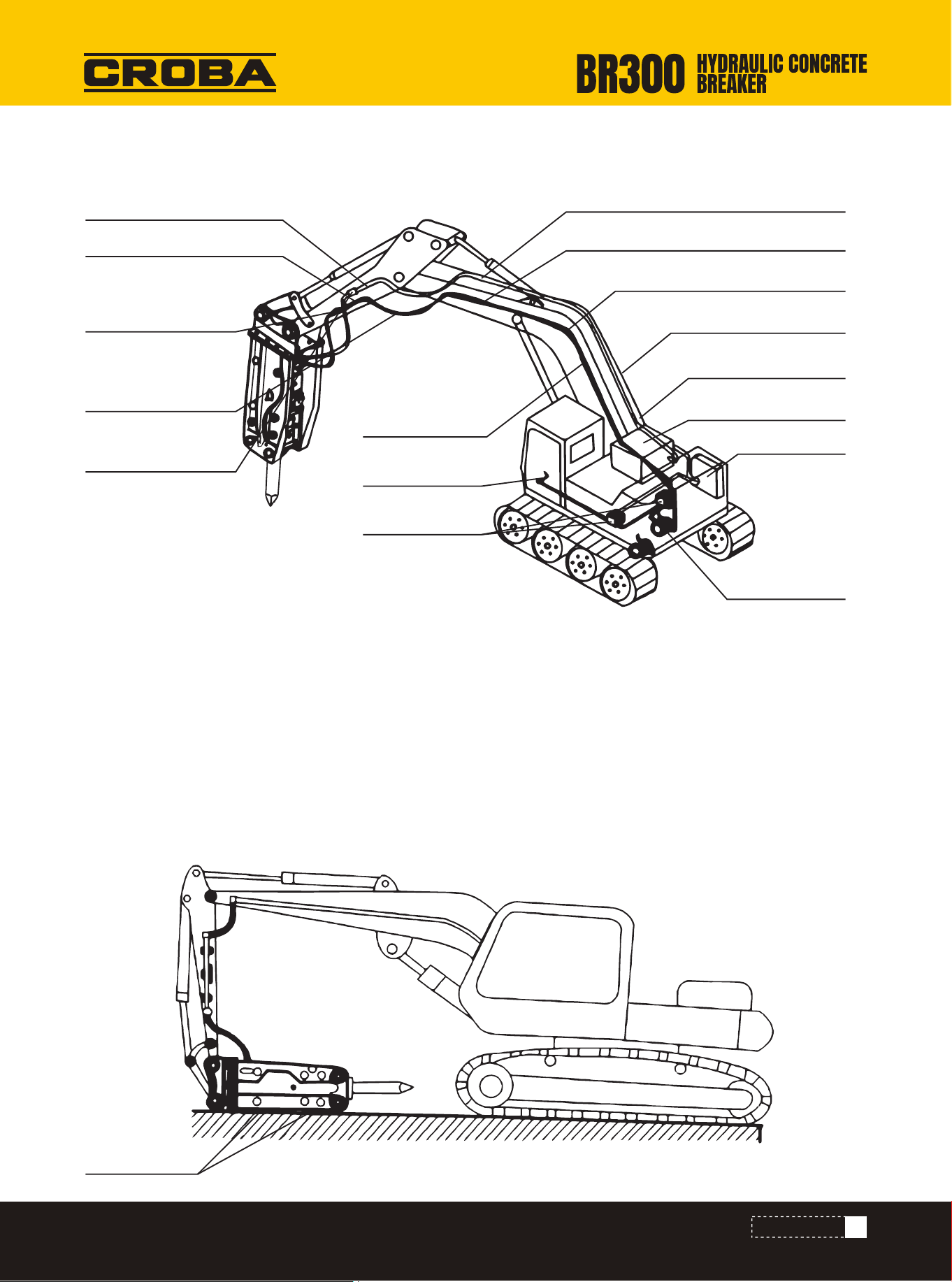
25
When bucket and breaking hammer work in turns, the breaking hammer is connected to excavator with two hydraulic
oil tubes and two shaft pins; therefore the bucket and the breaking hammer are very easy to replace each other. But
impurities are very easy to be mixed into the hydraulic oil duct, so follow the steps below when dissembling and
installing:
1) Choose a smooth and clean place, better in the repairing shop; after the excavator is driven in, turn off the engine
and master switch. After that, if the pressure of excavator hydraulic oil tank is high, then release the pressed air in
the tank. Then place the excavator according to Figure 5-1. This makes it very easy to replace breaking hammer and
bucket.
Installed onto an Excavator
Precautions for Installation
FIG 5-0
FIG 5-1
INSTALLATION
P1B (Steel Pipe 1B)
P1A (Steel Pipe1A)
P2B (Steel Pipe 2B)
P2A (Steel Pipe 2A)
H3 (Hose 3)
P3B (Steel Pipe 3B)
H2 (Hose 4)
Hydraulic Oil Tank
Oil Cooler
Hydraulic Pump
Operation Valve
Foot Valve
SA Stop Valve A
H2 (Hose 2)
H2 (Hose 2)
SB Stop Valve B
Wooden Block
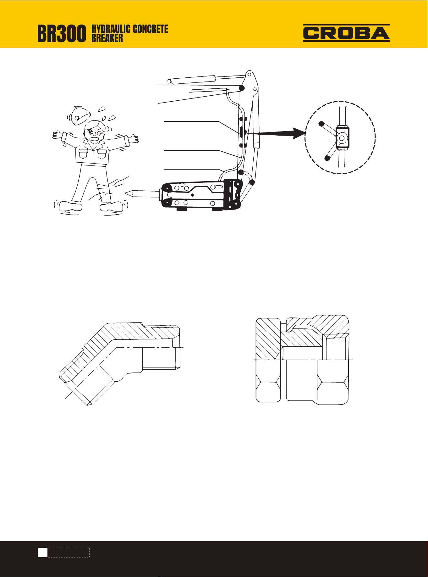
26
2) Rotate the stop valve at 90° which is installed at the end of the small arm to prevent hydraulic oil outflow.
3) Turn loose the hydraulic hose joints at the side of the small arm, at this time, there will be a small amount of
hydraulic oil overflow, use an empty container.
4) To prevent mud, soil, dust and other impurities from getting into the tubing and joints, caps should be put on
straight joints and 60° elbow joints and screwed up.
These joints are used to connect low pressure and high pressure hoses. While the bucket is working, use joint caps
to cover the joints at the side of the small arm and prevent the dust.
FIG 5-2
FIG 5-3 FIG 5-4
INSTALLATION
Stop Valve
Joint
Oil Tube
Wrench
Fully Open Position
Fully Close Position
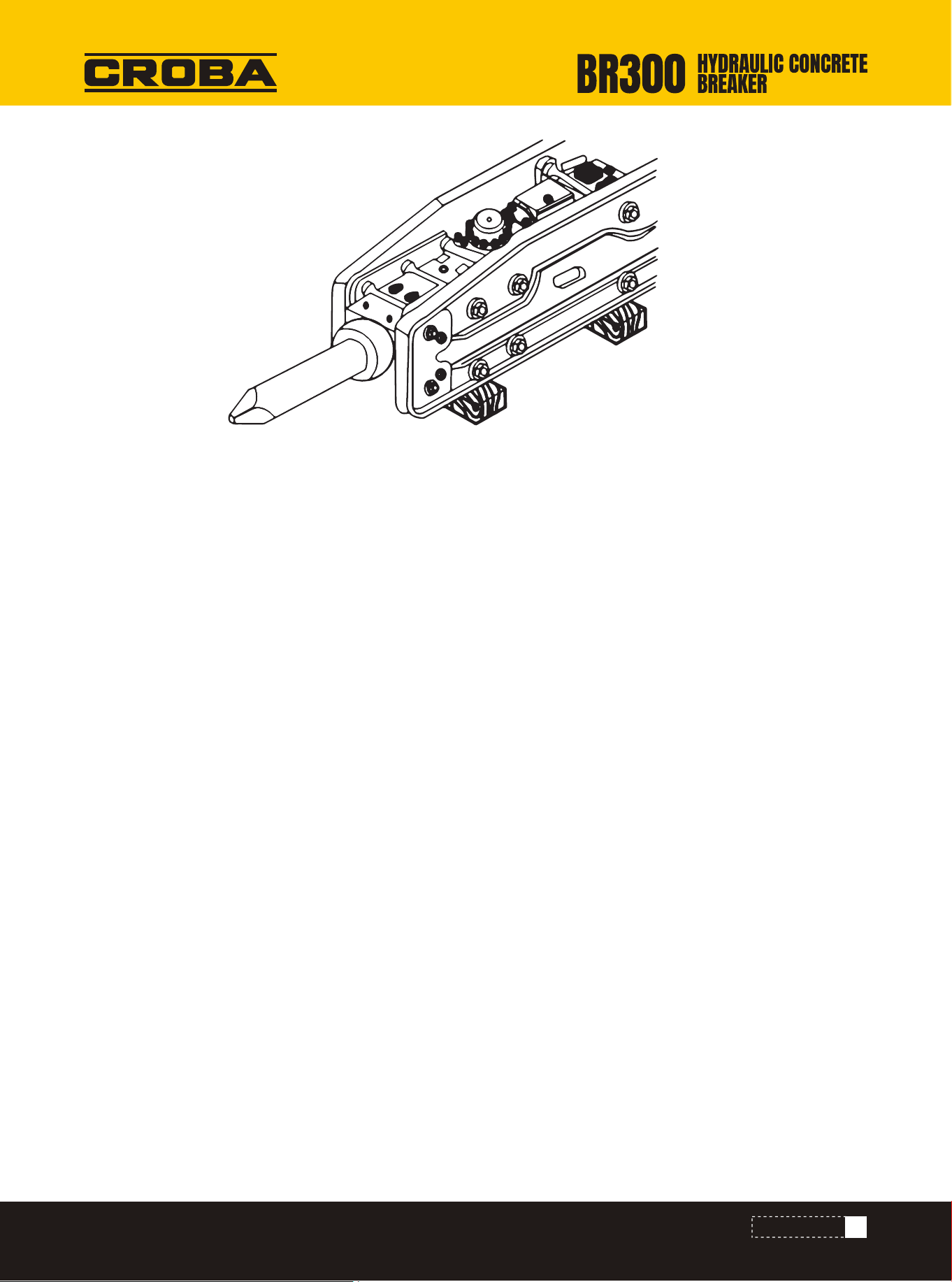
27
5) Draw out the shaft pin that connects the bucket and the small arm, then dismantle the breaking hammer, replace
the bucket and go back to work; when the hammer is placed outdoors, it should be cushioned with wooden blocks,
and covered with canvas or similar waterproof fabrics. Furthermore, if the hammer is not going to be used for a
while, all parts should be cleaned and lubricated and then stored indoors.
6) The steps of installing the breaking hammer are the exact opposite of the dismantling; clean the bucket or other
operational hoses and joints if they are dirty; please use authorized or recommended light oil or detergent for the
cleaning.
FIG 5-5
INSTALLATION
28
Check Items
MAINTENANCE
How to MaintainCheck Points
Loosening or Loss of
Bolts and Screw Caps
• Main Body Screw
• Guard Plate Screw
Check if it is loose
Screw up the bolts again
Hose parts are loose,
hose damaged and
oil leaking
Abnormal oil leakage
• Oil pressure duct of breaking device
• Oil pressure hose
• Connection part of back body and oil
cylinder
• Front body and steel-rod
Re-screw up the loose parts
Replace the severely damaged parts
Please contact your local sales or service
offices
Abnormal steel-rod
wearing and damage.
Lubrication
Volume and
contamination of
hydraulic oil
Loss of rubber pin
and fixing ring
Damaged, broken or worn-out steel-rod
should be immediately replaced or repaired.
The excessively damaged steel-rod should
be replaced and should not be used again.
The quality change of hydraulic oil varies
with different working environments. The
simplest way to judge the quality change is
to observe the oil color. If the quality
deterioration is severe, please get rid of the
oil from the tank immediately and after
cleaning the tank, fill new hydraulic oil.
Immediate repairing should be made to
avoid risk.
• Steel-rod
Pour lubricant from lubricant input hole
of front body
• Lubricate with lubricant both before
work and after working continuously
for two and three hours each time.
• Pour lubricant five to ten times
• Rubber Pin
• Buckle
• Conditions of hydraulic oil
MAINTENANCE
Before operation, please confirm the following points have been checked.
Routine Inspection
29
MAINTENANCE
Warning
When delivering breaking hammers, the following steps should be taken for filling its upper body with
N2 and operating it.
Warning
Prior to filling N2, check equipment surroundings to ensure its safety, and upper body does not allow
filling of other gas, except N2. As upper body is filled with N2, do not get close to the front part of
steel-rod. When finished, the steel-rod of breaking hammer will stretch out automatically.
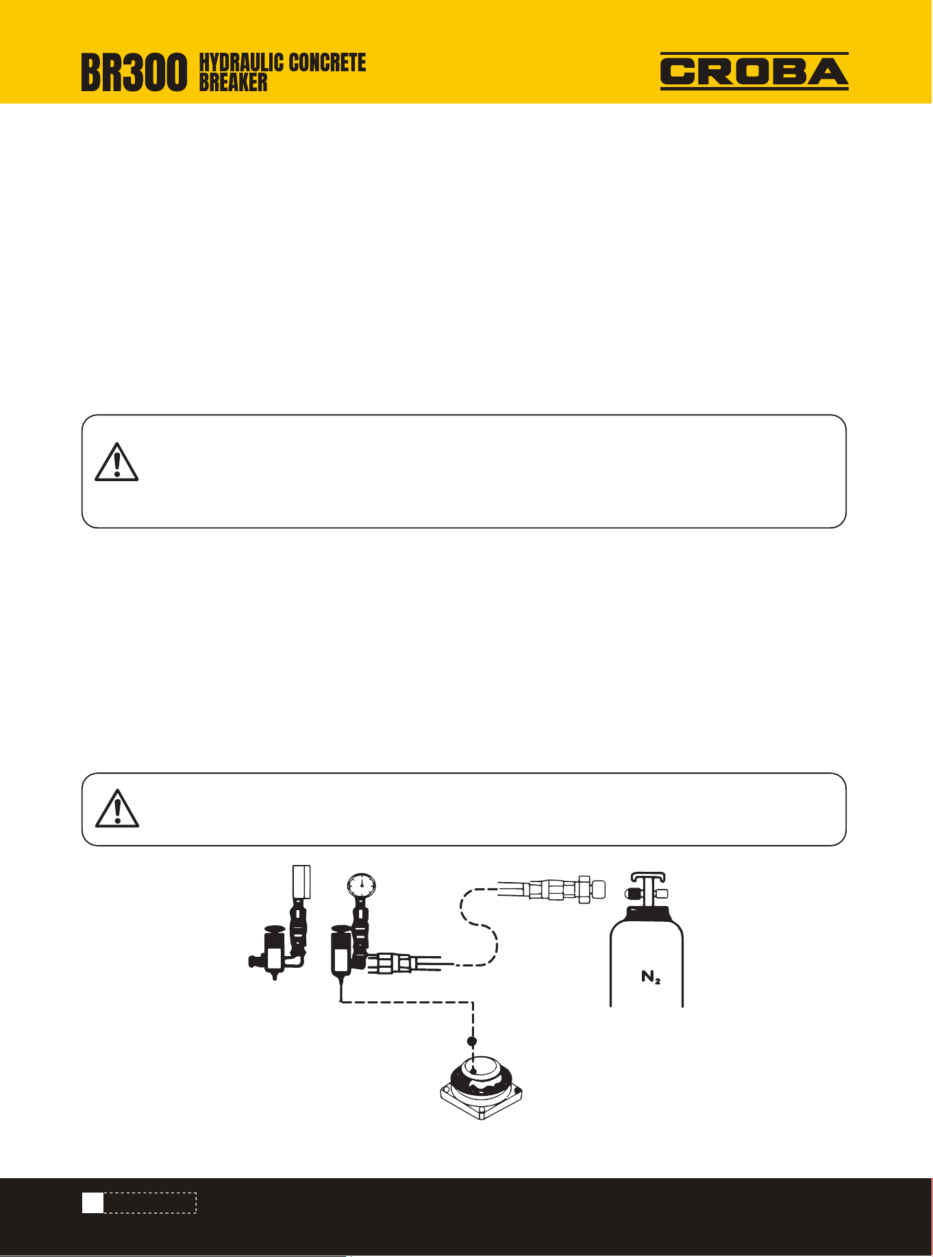
As hydraulic pressure breaking hammer is delivered out of the plant, its upper body has no N2 filled. Once its upper
body is filled with N2, the piston's front part will stretch out of cylinder. In such a case, the piston will get rusty as
breaking hammer is idling for a long time.
Precautions for Delivery
Check Nitrogen (N2)'s Refilled into Upper Body
FIG 6-1
Upper Body
30
MAINTENANCE
Notice
When finishing gas filling for upper body based on Step 1-8, turn the handle of triple valve anti-clock-
wise first, and remove the triple valve of charge valve of upper body later. However, if pressure in
upper body needs to be regulated, the next Step 9-13 should be taken.
Warning
Accumulator can only be used for N2, and other gases are not permitted
1) Connect a pressure gauge with triple valve, then turn the handle of triple valve anti-clockwise.
2) Connect charge hoses with nitrogen cylinder.
3) Dismantle plug screw from breaking hammer, then install triple valve on the charge valve of upper body. (Ensure
triple valve is installed with O-ring.)
4) Connect the other end of charge hose to triple valve.
5) Turn upper valve handle of anti-clockwise to discharge N2, then slowly turn the handle of triple valve clockwise to
the set charge pressure.
6) Turn the handle of triple valve counter-clockwise to close, then turn the valve handle of nitrogen cylinder clock-
wise to turn off N2.
7) Charge hose dismantled from triple valve should be covered with its cap.
8) Turn the handle of triple valve clockwise, and check the charge pressure in upper body again.
9) Remove charge hoses from triple valve.
10) Install triple valve tightly on charge valve.
11) When turn the handle of triple valve clockwise, pressure value in upper body will appear on pressure gauge.
12) If N2 pressure is a bit lower, Step 1-8 should be taken again till pressure rises to the set value.
13) If N2 pressure is too high, turn the regulator of triple valve anti-clockwise slowly, with atmospheric pressure
discharged out of upper body; when pressure gauge shows appropriate correct pressure value, close the regulator
clockwise. Once pressure too high, breaking hammer can not work normally. Ensure atmospheric pressure
conforms to the set pressure value, and ensure triple valve is installed with O-ring.
Check N2 filled into accumulator
Accumulator
FIG 6-2
31
MAINTENANCE
Notice
Prior to loosening fastening bolts, discharge all gas pressure in upper body Entirely. Otherwise, when
fastening bolts are removed, upper body will spring out and lead to severe consequences.
1) Check charge pressure
(1) Install adaptor and pressure gauge to triple valve.
(2) Turn the handle of triple valve anti-clockwise.
(3)Remove the plug screw of accumulator and turn triple valve tightly.
(4) Turn the regulator (2) anti-clockwise slowly, and observe the charge pressure value indicated on pressure gauge.
(5) Ensure the charge pressure value, and tighten the regulator (2) completely.
(6) Loosen the regulator (2) to discharge N, in triple valve.
(7) Remove triple valve, and tighten plug screw and cap. (Ensure plug screw and cap is installed with O-ring.)
2) Fill accumulator with N2
(1) Check charge pressure based upon the above-mentioned same steps, then remove the cap of triple valve.
(2) Connect both ends of charge hose with triple valve and N2 steel cylinder separately.
(3) Turn the handle of triple valve clockwise.
(4) Turn the valve handle of N2 tank anti-clockwise to fill accumulator with N2.
(5) Tighten the regulator (2) entirely.
(6) Turn the valve handle of N2 tank clockwise till tap is turned off.
(7) Loose the regulator of triple valve to discharge the rest Nain charge hose.
(8) Remove charge hoses out of triple valve and N2 cylinder.
(9) Remove charge hose, then regulate pressure according to the method stated on Step 1 <Check charge pressure>.
(10) Fill accumulator with N2, check each screw hole, regulation valve, etc. on its main body to see if there is gas
leaking.
1)Before loosening the fastening bolts, discharge N2 in upper body entirely.
2)Remove all fastening bolts and meanwhile check them whether cracked and damaged.
3)When fastening bolts are installed, tighten them at diagonal direction one after another, rather than tighten a bolt
at one go.
4) Use the set spanning torque wrench, see the moment form at Section 6-4(2)
Check and Replace Fastening Bolts
3
2
1
4
FIG 6-3
32
MAINTENANCE
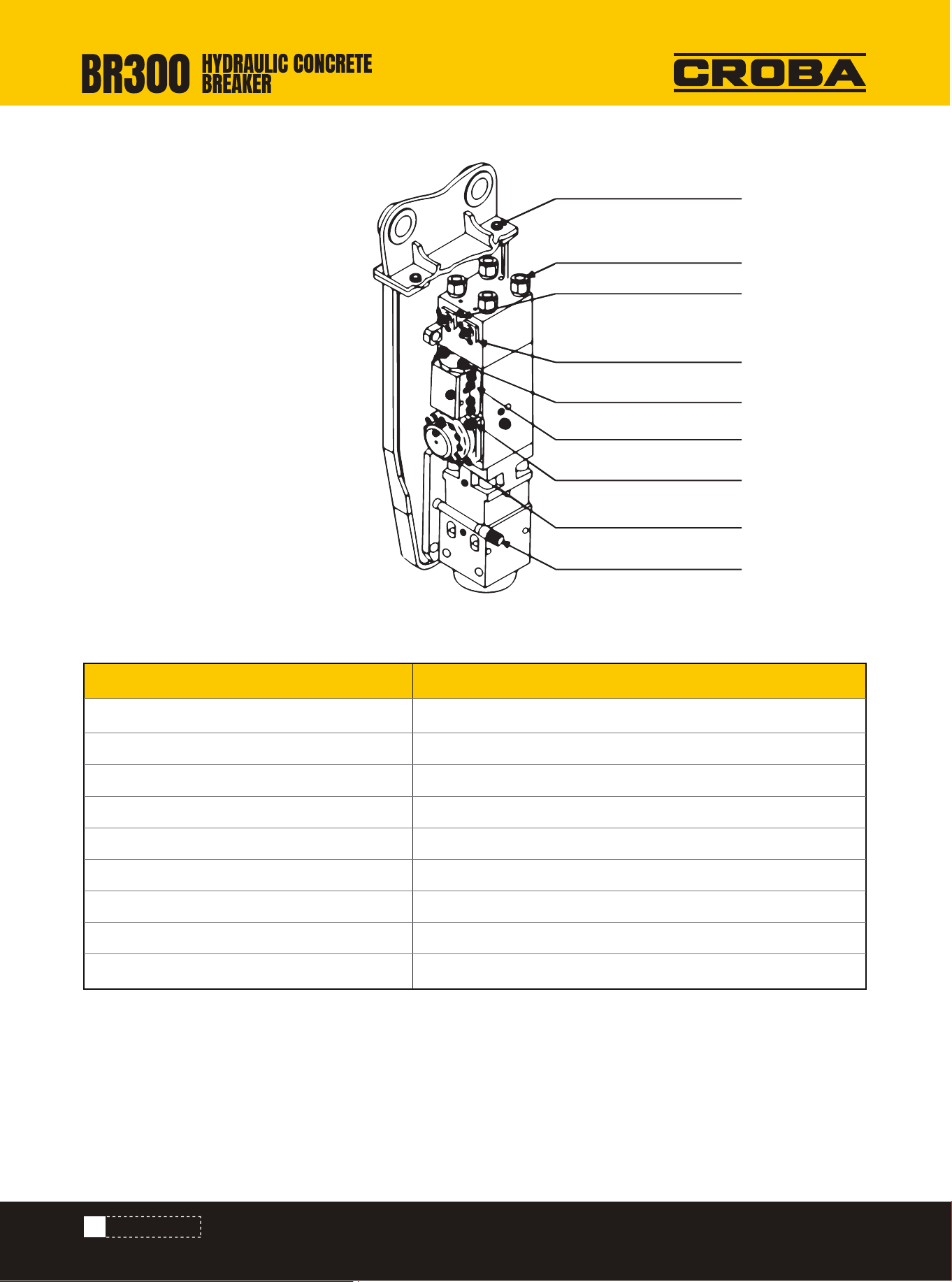
CLASSIFICATION
Install cap bolt K.g.m (N.m)
Thorough bolt K.g.m (N.m)
Charge valve ass'y K.g.m (N.m)
Flange bolt K.g.m (N.m)
Valve cap bolt K.g.m (N.m)
Valve body bolt K.g.m (N.m)
Bolt of accumulator K.g.m (N.m)
Coyer board bolt of accumulator K.g.m (N.m)
Clamp bolt K.g.m (N.m)
225(2250)
150(1500)
35(350)
20(200)
60(600)
45(450)
60(600)
45(450)
250(2500)
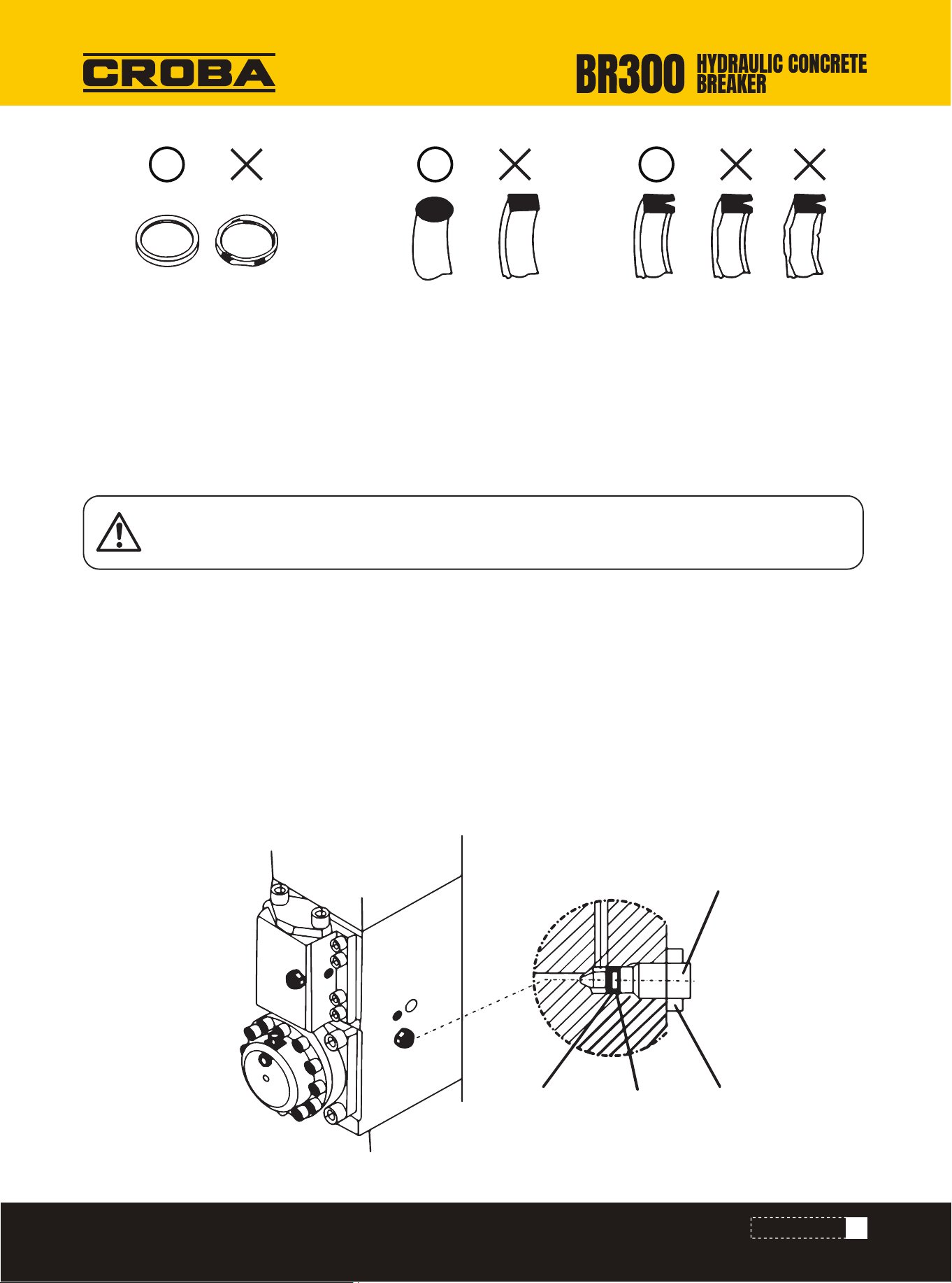
1) Once hydraulic oil leaking is found with breaking hammer, change damaged sealing elements immediately. To
clearly identify the damaged place of sealing elements, please see the picture blow:
Check and Replace Sealing Elements
Moment
FIG 6-4
Install cap bolt
Thorough bolt
Charge valve ass'y
Flange bolt
Valve cap bolt
Valve body bolt
Bolt of accumulator
Cover board bolt of
accumulator
Clamp bolt
33
MAINTENANCE
Notice
In actual work, sealing elements should be changed every 1000h.
2) When sealing elements is found damaged, causes must be trased and handled in time.
3) When exchanging sealing elements, apply grease on sealing elements and sockets, and tow by middle finger
based on marks, grasp with thumb and insert the sealing socket tightly. Never use too much strength to deform
sealing elements.
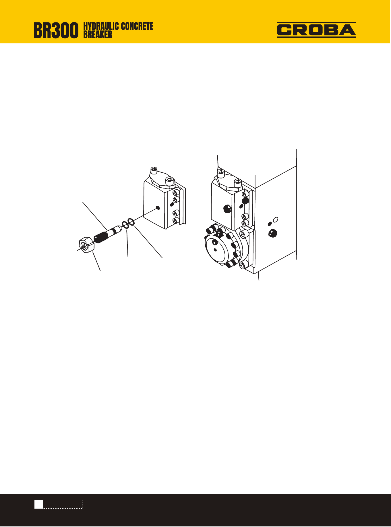
Regulator that is used for regulating striking frequency is the authorized equipment for our breaking hammer.
Striking frequency should be changed at any time as per work condition for a more efficient striking operation. And
its basic theory is to regulate striking frequency through changing piston stroke, and at the same time, keeping work
pressure and hydraulic oil flow unchanged. Regulator should be installed on the right side of oil cylinder of breaking
hammer.
For regulating striking frequency, use wrench to remove the nut at the front part of regulating screw of regulator, and
then revolve regulating screw to the inside bottom so as to get the lowest striking frequency, and at the time, turn
the regulating screw externally 2 circles to get the max striking frequency.
After necessary striking frequency regulation, please install the nut at the front part of regulating screw to its original
place and tighten it
How to Reset the Striking Frequency
Supporting ring-worn out O-ring and dust-proof seal
ring worn out and damaged
U type expansion ring, damping vibration
reduction ring and sealing ring
deformed, worn out, twisted and damaged
FIG 6-6
FIG 6-5
O-ring NutSupporting ring
Regulator (screw)
34
MAINTENANCE
How to operate:
When excavator provides breaking hammer with insufficient oil, control valve receives rated operating pressure by
lowering striking frequency. On the contrary, when there is too much oil supply is, control valve keeps rated operat-
ing pressure by improving striking frequency.
How to regulate control valve:
When control valve closes entirely to stop operating oil flow, regulate the notch on control valve aiming at the place
marked with "1" as shown in the following picture. For the present place, we generally recognize it as "O" operating
oil flow condition. If the regulator on control valve is loosened, then operating oil capacity can be started to increase.
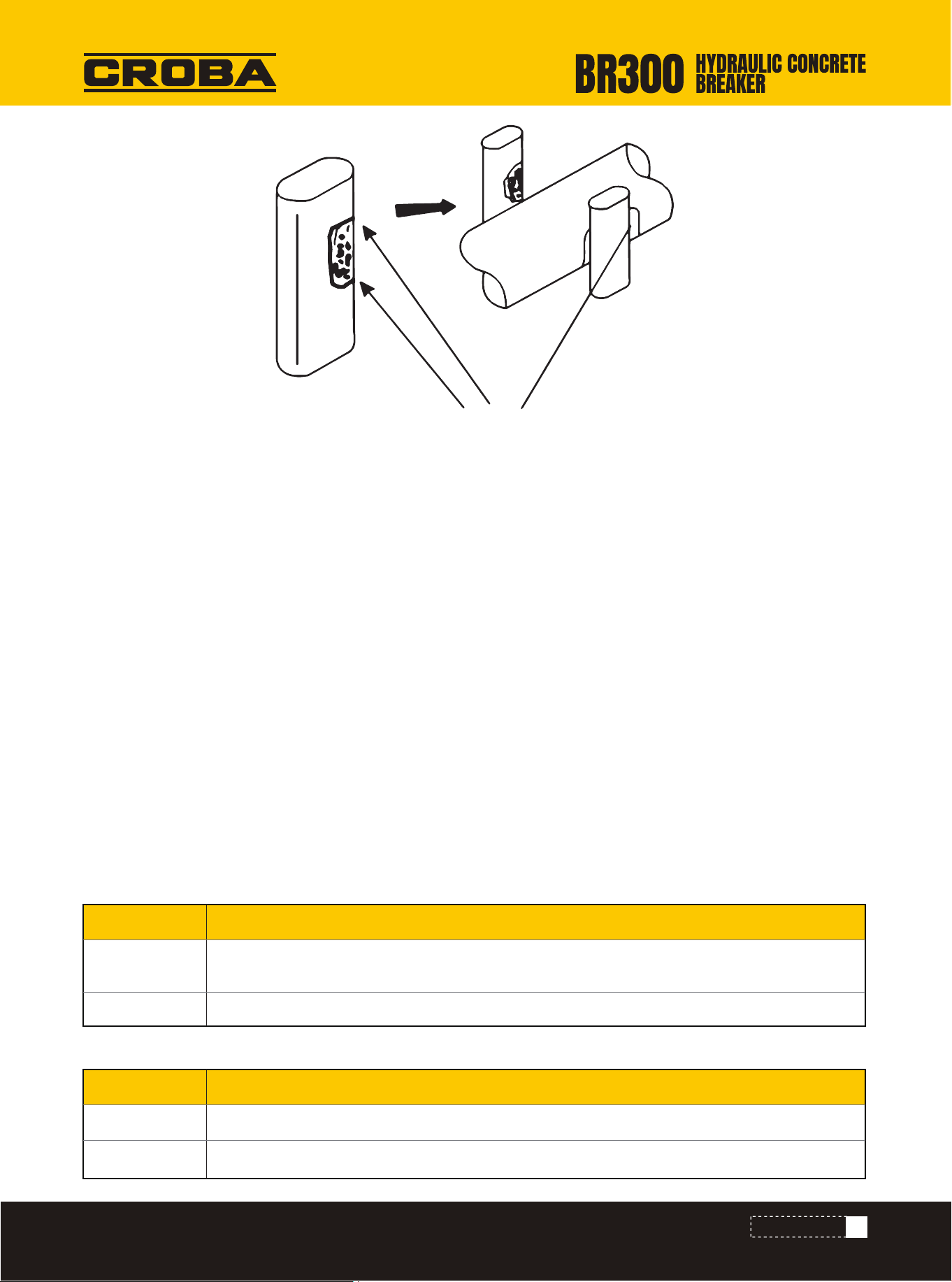
1) When they are damaged or worn out, we greatly recommend you to change the following items:
-Steel-rod
-Lower body (it has to be replaced in maintenance shop)
- Flat-pin of steel-rod Lock pin (lock pin of steel-rod)
-Rubber plug screw (lock pin) Hydraulic sealing elements
-Bolt at support side
-Hydraulic hoses
2) We recommend users should prepare wearing spare parts, such as flat-pin and lock pin of steel-rod, rubber plug
screw, bolt and hydraulic hoses.
3) When actual work reaches every 600h, hydraulic sealing elements change is required.
4) Flat-pin of steel-rod
-When flat-pin of steel-rod is seriously deformed, the change becomes quite difficult.
Therefore, the interface between its flat-pin and steel-rod should be changed after every 100-150h operation, thus
both surfaces of flat-pin of steel-rod can be totally used. If the used steel-rod is not a genuine one, we can not guar-
antee the good operation condition of relevant parts for breaking hammer.
Adjust Oil Supply with Control Valve
Wearing Parts
FIG 6-7
Valve regulator (screw)
Nut
Supporting ring O-ring
35
MAINTENANCE
CYCLE MEASURES
Every 3 months
Every 6 months
To ensure good operation condition with sealing elements, leave the breaking hammer top
side down
Check corrosion condition of all sealing parts and bolts inside oil cylinder
CYCLE MEASURES
Every 3 months
Every 6 months
Check sealing elements
Check sealing elements and corrosion condition
As regulating the direction of flat-pin of steel-rod, its surface should be placed on the side of steel-rod.
-As changing wearing parts, check the worn condition of wearing elements such as crack and scrach, particularly
after abrading burr of flat-pin and high spot on the surface, more check should be done carefully.
-First of all, abrade worn parts of lower body and flat-pin of steel-rod, and then change steel-rod; abrade bruised and
damaged parts of lower body, then change new flat-pin of steel-rod.
-Breaking hammer should be stored at the place with little temperature change.
-Remove steel-rod and discharge N2 inside.
-Apply grease on piston end, and steel-rod and lining should be applied with anti-rust oil.
-As no lubricating can be done, steel-rod must be constricted so that piston can enter oil cylinder.
-The adapter connecting excavator and main parts should be covered with cap so as to prevent dust from oil ducts.
-Leave the breaking hammer upright. If impossible, breaking hammer should lie on the flat floor with square timber
sticks underneath.
-If breaking hammer lies above square timer sticks more than 6 months, please check the corrosion condition of all
sealing parts and bolts in oil cylinder before operation.
1) Storage method
2) Prior to work
Notice for Long-Term Storage
Abrade burr and high spot on the surface by grinder or dresser
FIG 6-8
36
MAINTENANCE
Notice
If breaking hammer lies above square timer sticks more than 6 months, please check the corrosion
condition of all sealing parts and bolts in oil cylinder before operation.
1) Operation oil
-Breaking hammer uses the same operation oil as excavator does.
-When breaking hammer operates continuously, oil temperature will rise, so please check oil viscosity at this
moment.
-The too high viscosity of operation oil will result in un-smooth operation, irregular strike while air pocket in operation
pump and viscose with big valve may occur.
-If the viscosity of operation oil is too thin, low operation efficiency may occur due to inner leaking, and oil seal and
liner may be damaged due to high temperature.
-In the operating period of breaking hammer, supply operation oil before dipper works, because impurity oil can
cause operation disorder with hydraulic parts, breaking hammer and excavator, which will lower their operation
efficiency.
-Operation hydraulic oil should be added after breaking hammer's initial operation work for 250 hand every 500 h
later on.
2) Oil duct filter
-Because impurity in hydraulic oil will shorten the service life of hydraulic parts and even cause oil duct stop, oil filter
should be used for removing impurity from oil.
-Oil duct filter should be changed Initial operation work for 50h and the next every 125h.
-Because of spare parts worn out, repair and maintenance as well as oil change and recoiling, impurity, dusts and
others can enter hydraulic tubes.
-Installing oil duct filter, the rated capacity of filter should suit to the maximum oil-return capacity of operation
pressure.
3) Oil duct cooler
-The purpose of using oil duct cooler is to lower operation temperature of hydraulic oil.
-During hammering operation, it is recommended to change the original oil duct cooler or install auxiliary cooler if oil
temperature rises too high.
Operating Oil and Filter
Oil leaking area Causes and measuresCondition
Between steel-rod and
front cover
Between main valve and the
surface of oil cylinder
Between oil cylinder and
upper body
Between oil cylinder and
upper and lower bodies
Breaking hammer surface
Valve body and bolt cap
For severe oil leak, check whether it
is hydraulic oil or grease
Oil leaking at the connection
between big valve and hose
Oil leaking with re installed valve
body after overhaul
Oil leaking with reinstalled valve
body after overhaul
Oil leaking due to loose thorough-bolt
and nut
Oil leakage
Oil leaking now
Change damaged sealing elements
Tighten again the loosened hose
and bolt of breaking hammer
Normal condition: outflow of
lubricant and anti-rust oil applied
during installation
Normal condition:
Clean the oil used, and if checking
finds
damaged oil seal, change anther
seal.
Installed bolts on oil cylinder
surface are loosened and should be
tightened again while oil seal
should be changed.
Re-tighten
Change damaged O-ring
37
TROUBLE SHOOTING
TROUBLE SHOOTING
Even if oil leakage occurs, it's unnecessary to change parts in every case; check the leaking condition as per the
following form. Users can handle it by themselves before calling their distributors.
Leakage of Hydraulic Oil
A
B
C
D
E
F
38
TROUBLE SHOOTING
Breaking Hammer Not Performing Well
MeasuresMain causesCondition
Breaking hammer can't strike
Striking frequency gets normal
first, but strikes irregularly
later on.
weak striking power
Too low oil temperature
Inappropriate operation of main valve
Pressure in upper body and over flow
Lower pressure set for valve
Hydraulic oil pump is not working
with good performance
Oil shortage resulting in rising oil
temperature
Too lower pressure set for overflow
valve
Insufficient lowering pressure of
steel-rod
Too big clearance between steel-rod
and front cover
Hydraulic oil pump is not working
with good performance with much
higher back pressure
Lower atmospheric pressure in upper
body
Main valve with impurity inside
Piston and oil cylinder getting stuck
Excessive wearing on the top of
steel-rod
Too higher pressure in upper body
Oil temperature must reach at least
30℃
Check the operating buttons of
breaking hammer in driver's cab
Check pressure of N2 and overflow
valve
Contact excavator manufacturer
immediately
Check small and big arms of
excavator to supply enough
lowering pressure
Check the clearance between steel-
rod and front cover
Ask excavator manufacturers to
check oil way
Remove main valve for cleaning
Check atmospheric pressure
Check and overhaul
Remove steel-rod to check
Add hydraulic oil
Check atmospheric pressure
Check overflow valve pressure

39
TROUBLE SHOOTING
Preconditions for normal operation and prolonged service life for Mechmaxx series breaking hammers:
-use such grades of hydraulic oils (Grade P with frequency Q)
-use clean hydraulic oils
-conduct proper maintenance as per operation and maintenance manual.
When an agent receives a user's malfunction report, user would normally request agent for the quickest possible
actions for trouble shooting. The experienced engineer(s) dispatched by the agent shall check for possible causes,
confirm the trouble state so that sufficient measures can be taken to eliminate the malfunction. It is recommended
to entrust user to remove small trouble(s). should they fail to find out the causes, separate proper counter-actions
can be taken to solve it.
You may follow the corresponding measures for checking and solving problems in case there is any:
Frequent Problems
MeasuresMain causesCondition
Low striking frequency Atmospheric pressure too high
Insufficient lowering pressure of
steel-rod
Pressure set by overflow valve is
too low
Hydraulic oil pump does not operate
with proper performance
Too higher operation pressure
Check atmospheric pressure
Check small and big arms of
excavator to supply enough
lowering pressure
Check overflow valve pressure
Ask excavator manufacturer to
check oil way
Check set pressure
ActionsState CausesItems
Main
Body
Breaking hammer
not working
Striking gets
abnormal or stops
& grease enters
cylinder during
30-90 min
operation
-Insufficient power (PXQ)
-Insufficient falling pressure with rod
-Blocked tube
-Breaking hammer stuck
-Hydraulic oil sinking into upper cover
cavity
- Insufficient hydraulic oil
-Insufficient power (PXQ)
-Blocked tube
-Too high pressure in upper body cavity
-Oil seal damaged
- Immense grease flows into cylinder
-Check power
-Follow correct instructions
-Inspect and repair
-Check and replace worn parts
-Replace sealing components
-Add hydraulic oil
-Check power
-Inspect and repair
-Make adjustment
-Replace oil seal
-Discharge grease as required
40
TROUBLE SHOOTING
ActionsState CausesItems
Main
Body
Rod broken
Rod-head softened
Difficult to
dismantle or install
rod flat-pin
Excessive clearance
between the
support and the
breaking hammer.
Prematurely worn
front cover
Low striking
frequency
Weak striking force
Rod-head broken
Conduct striking slantwise, removing
stones with the rod as crowbar
Continuous striking at a certain spot for
long time
-Insufficient power (PXQ)
-Insufficient falling pressure with rod
-Too high pressure in upper body cavity
-Pressure drop in upper body cavity
-Oil leak at the I/O
tube
-Oil leak between
the control valve
and the cylinder
-Oil leak between
the rod and the
front cover
-Oil leak between
the upper cover
and the cylinder
-Insufficient falling pressure with rod
-Insufficient power (PXQ)
-Rod broken in front cover
-Adopter loose and O-ring & support ring
damaged
-Adopter loose and O-ring & support ring
damaged
-Oil seal worn and damaged
-Hexagon-socket bolt damaged or
thorough bolt nut loosened
-Check power
-Follow correct instructions
-Set to required air pressure value
-Add again Nitrogen (N2)
-Follow correct instructions
-Check power
-Replace rod and piston
-Tighten adopter and replace O-ring
& support ring
-Tighten adopter and replace O-ring
& support ring
-Replace oil seal
-Replace hexagon-socket bolt and
tighten thorough bolt nut
Max force used for striking from beginning
Flat-pin deformed
Bolts of clip plate loosened
Lacking grease lubrication
Exert force downward along the
direction of rod to check the
clearance of small-arm,
connecting-rod and flat-pin.
Find another breaking spot
Striking with lower speed for the
first 30min
Check whether normal
Re-tighten the bolts
Replace lower bushing or bushing
41
TROUBLE SHOOTING
ActionsState CausesItems
Main
Body
See if breaking
hammer operates
with fluctuation
Too fast with oil
temperature rise
Emulsification with
hydraulic oil
Too much drop
with engine rotation
Hose vibrating
from oil input
Hose vibrating
from oil return
Not well positioned
while breaking
stone with rod
Error in setting pressure of overflow valve
Not well ventilated with excavator.
Hydraulic pump worn prematurely and
tube blocked
Air-pressure too low or too high
Too big clearance betwn smallarm,
connecting-rod or flat-pin and shaft lining,
causing premature wearing.
Check rod and fix it tightly to
breaking hammer
-Insufficient output power
-Drop with engine performance
-Too low oil temperature
-Reduce pressure inside upper-body
cavity
-Lower position of accelerator
-Ask for check by excavator
manufacturer
-Pre-heat operation
Too low oil input
Water in oil
Check and slowly increase pressure
Reset breaking hammer Check
and replace hydraulic pump
Check oil quantity
Reset air-pressure
Replace hydraulic oil immediately
42
MAINTENANCE INSTRUCTIONS
MAINTENANCE INSTRUCTIONS
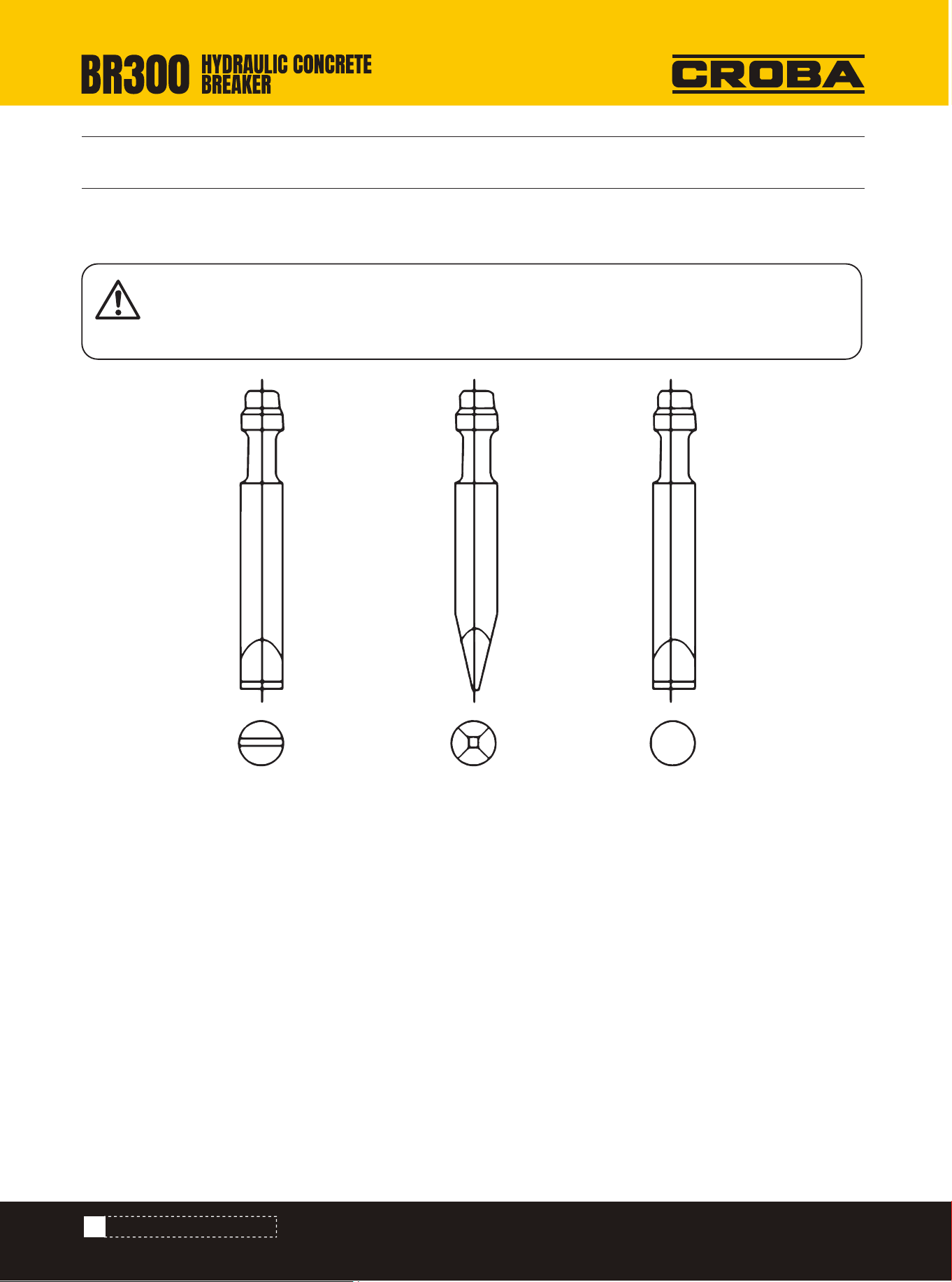
A: "-” head type of steel-rod
- applicable for excavation and ditch-digging with various soft and neutral lamination rocks
B: "+" head type of steel-rod
-applicable for crashing granule and neutral concrete or soft non lamination rocks.
- also applicable for secondary blasting and crashing for soft and neutral hard rocks
C: Tack steel-rod
-Applicable for crashing medium-hardness racks or small cracking rocks, making them even smaller.
1) Selection of steel-rod
Attention
A proper selection of steel-rod suitable for operation is extremely important not only for improving the
working efficiency of breaking hammer but for prolonging the service life of the steel-rod as well.
Warranty Instructions for Steel-Rod
A B C
43
MAINTENANCE INSTRUCTIONS
2) Claim standards for steel-rods
Mechmaxx steel-rods are manufactured through strict process and quality control, not only in terms of acceptance
of materials processed but grinding and even final finishing as well. Documents of steel-rods are well preserved,
covering the whole quality tracing records from shipment of steel-rods up to their normal service life. However, the
service life of rods vary greatly with the working conditions, operation mode or the types of rocks to be crushed,
apart from the factors related to rod quality itself. It is therefore difficult to determine the standard service life of
steel-rods.
The following claim standards apply to each of the malfunctions listed below during use of breaking hammers, so
that users may have a proper use of our products and their service life can be maintained.
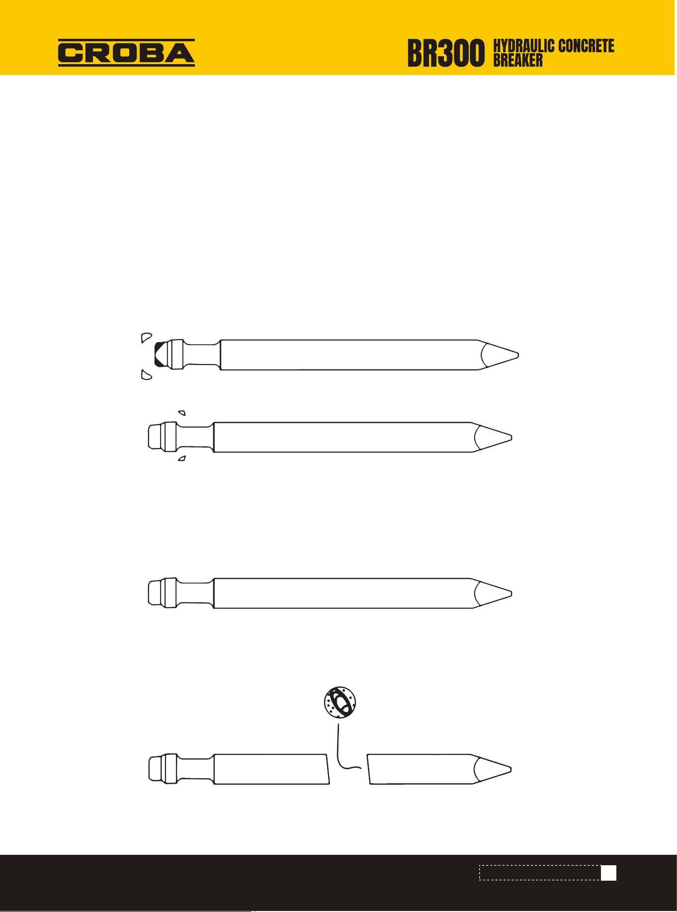
(1) Damage with the striking face of plunger or with contact point of rod flat-pin (Fig 8-2, 3)
It rarely happens that the striking face of plunger or with contact point of rod flat-pin is damaged. This damage
occurs because there is not a proper parallelism with the striking point of plunger and rod, which has resulted in an
excessively concentrated striking force to the angle of rod. Claim can be made in this case.
(2) Damage with the striking face of plunger or with contact point of rod flat-pin (Fig 8-4)
Adopting first-class material, Mechmaxx steel-rods receives proper heat treatment and therefore possesses great
strength against stress. In case of a too thin and long plunger, the rod tip may have plastic deformation. Brittleness
occurs due to insufficient strength or improper heat treatment. All these contribute to malfunction, which can be
claimed for.
If fatigue crack start appears inside the rod as shown in Fig 8-5, this indicates defects with material. It is therefore
claimable in this case.
FIG 8-2
FIG 8-3
FIG 8-4
FIG 8-5
44
MAINTENANCE INSTRUCTIONS
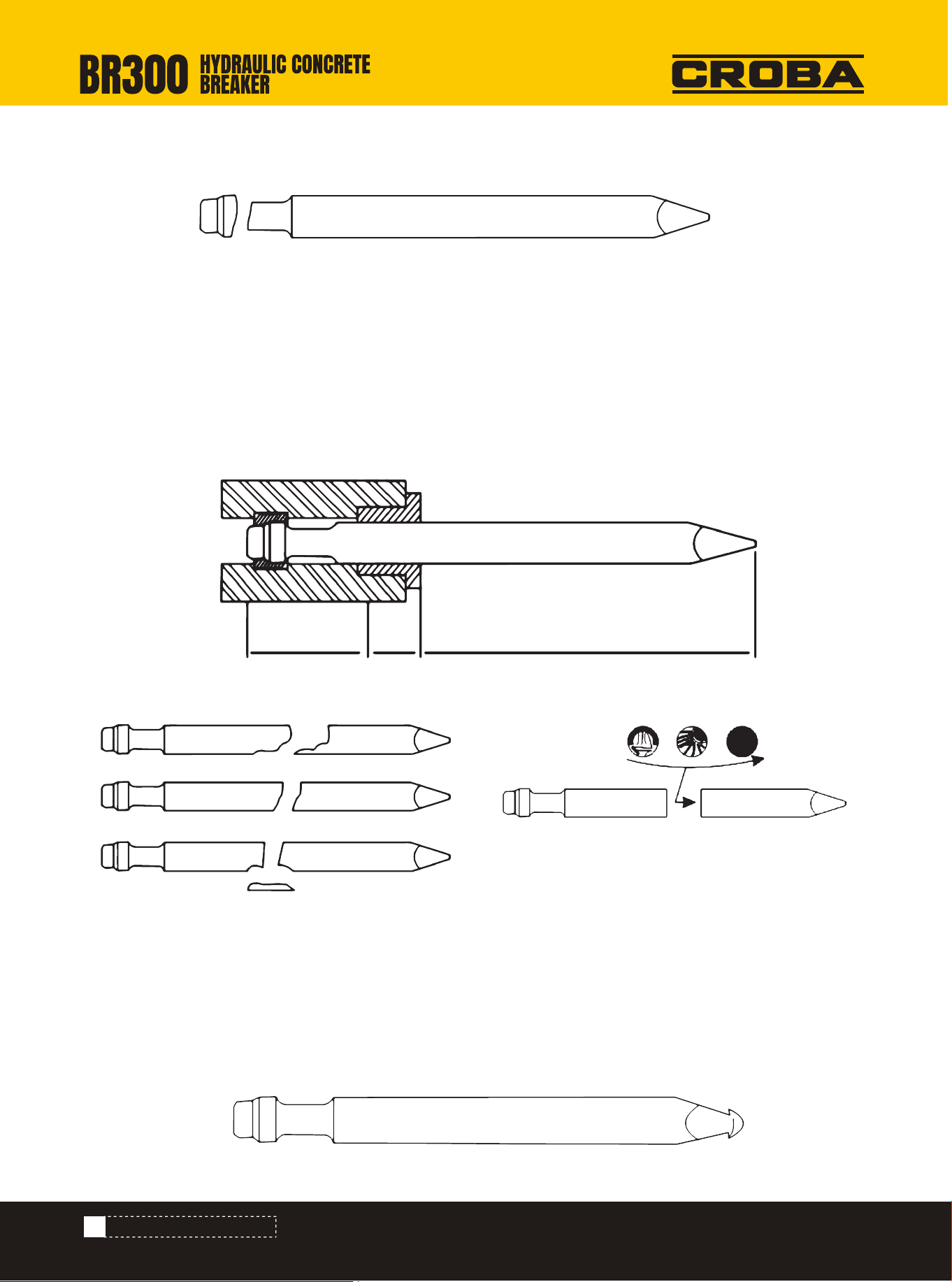
(3) Crack/Damage beyond reference line (Figs 8-8, 9)
If there is any crack/damage somewhere beyond the front bush of the rod (as shown in Fig 8-8, refer to the reference
line Fig 8-7). This may be due to the excessive bending overload the rod has taken. When the rod in inserted into
something crashed and pulled or pushed, or when the rod cannot strike in from the surface of the crashed articles
and get stuck to receive pushing, the rod then will take bending load. Generally, cracks would appear as shown in Fig
8-9, together with crack/damage of clam-shape due to concentrated stress because of bending load. They will
spread around quickly from the crack. This may also happen if cracks occur to the rod during operation. Claim for
crack/damage beyond the reference line will not be accepted.
(1) Steel-rod head is squeezed flat (Fig 8-10)
With good heat-treatment, the steel-rod of Mechmaxx breaking hammer has a sound performance against wearing
and cracking, and therefore it cannot be squeezed flat (Fig 8-10) in normal working condition. However, if the rod
strikes continuously for a long time but still cannot crush or penetrate the object, plastic deformation (squeezed flat)
may occur, rather than worn-out. Therefore, improper operation is the main reason for the above phenomenon. And
consequently this does not fall into the scope of claim.
If there is any crack in any direction somewhere with the sleeve of the steel-rod, as indicated in Fig 8-6, this shows
defects with material or improper heat treatment. Use can claim for this breakage problem.
FIG 8-6
FIG 8-7/8/9
FIG 8-10
Beyond reference line
Reference linene
Within reference
line