MANUAL 10094-SB REV 0 (04/21)
$21.00
GAS SKILLETS
MANUAL SECTION CO
IMPORTANT FOR FUTURE REFERENCE
Please complete this information and retain this
manual for the life of the equipment:
Model #:
___________________________
Serial #:
___________________________
Date Purchased:
_____________________
WARNING
Improper installation, adjustment, alteration, service or maintenance can cause property damage, injury
or death. Read the installation, operating and maintenance instructions thoroughly before installing or
servicing this equipment.
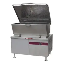
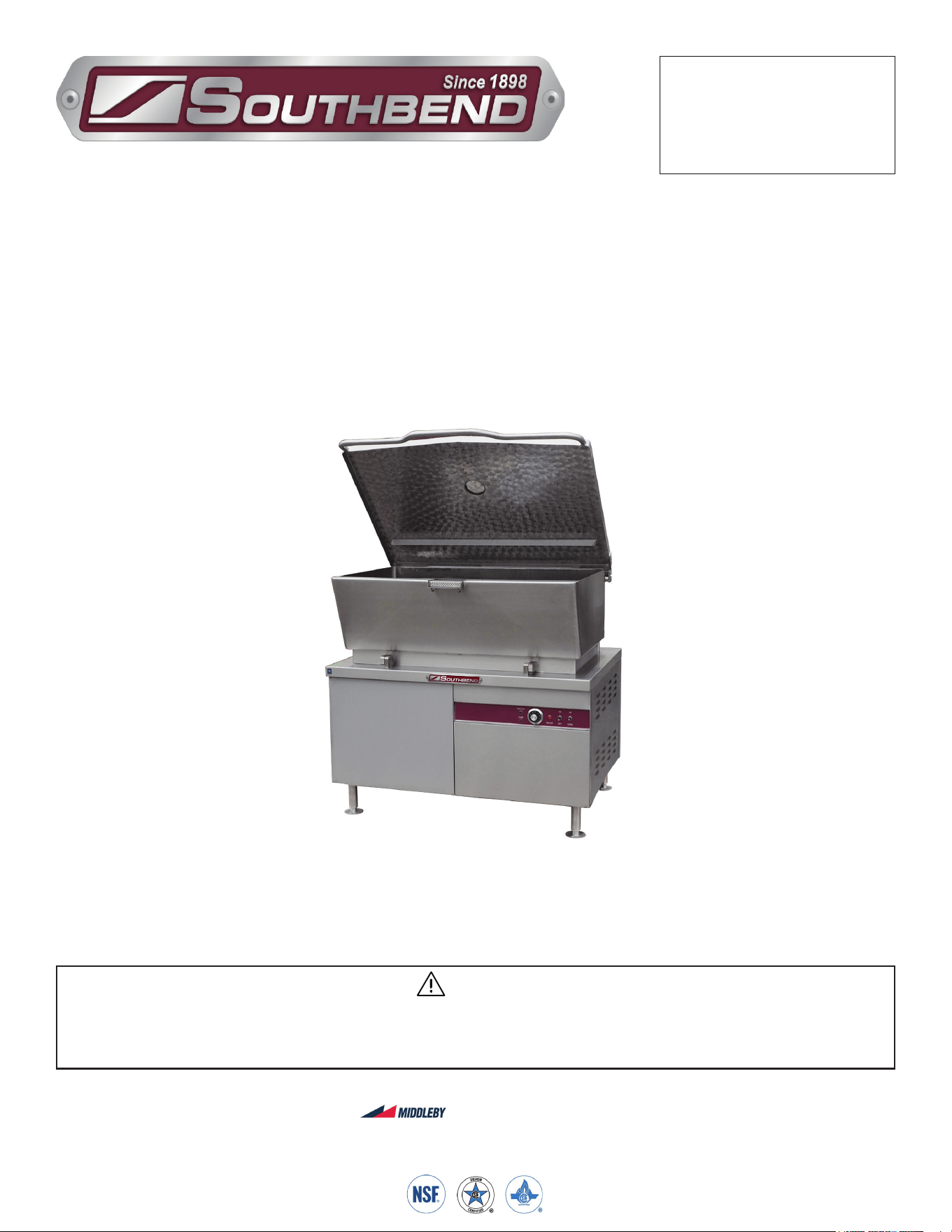
Model BGMTS-60
Gas Skillets
BGMTS-30, BGMTS-40 & BGMTS-60
Installation & Operation Manual
SOUTHBEND STEAM
A Middleby Company
1100 Old Honeycutt Road Fuquay-Varina, North Carolina 27526 USA
www.southbendnc.com
INSTALLATION & OPERATION MANUAL 10094-SB REV 0 (08/21)
PAGE
2
OF 24
Gas Skillets
SAFETY PRECAUTIONS
Before installing and operating this equipment, be sure everyone involved in its operation is fully trained and aware of
precautions. Accidents and problems can be caused by failure to follow fundamental rules and precautions.
The following symbols, found throughout this manual, alert you to potentially dangerous conditions to the operator,
service personnel, or to the equipment.
CAUTION
WARNING
NOTICE
This symbol warns of immediate hazards that will result in severe injury or death.
This symbol refers to a potential hazard or unsafe practice that could result in injury or death.
This symbol refers to a potential hazard or unsafe practice that could result in injury, product
damage, or property damage.
This symbol refers to information that needs special attention or must be fully
understood, even though not dangerous.
DANGER
WARNING
Improper installation, operation, adjustment, alteration, service or maintenance can cause property damage, injury or death.
Read the installation, operating and maintenance instructions thoroughly before installing, operating or servicing this equipment.
NOTICE
This manual should be retained for future reference.
NOTICE
This product is intended for commercial use only. NOT FOR HOUSEHOLD USE.
Copyright © 2021 by Southbend Steam. All rights reserved. Published in the United States of America.
SPECIFICATIONS
IMPORTANT NOTES FOR INSTALLATION AND OPERATION
WARNING
This is the safety alert symbol. It is used to alert you to potential personal injury hazards. Obey all safety messages
that follow this symbol to avoid possible injury or death.
WARNING
FOR YOUR SAFETY:
Do not store or use gasoline or other ammable vapors or liquids in the vicinity of this or any other appliance.
PURCHASER: Instructions to be followed in the event the operator of this appliance smells gas must be posted
in a prominent location. This information shall be obtained by consulting the local gas supplier.
The appliance area MUST be kept free and clear of combustibles.
DO NOT obstruct the ow of combustion and ventilation air.
Adequate clearances MUST be maintained for servicing and proper operation.
Contact the factory, the factory representative or a local service company to perform maintenance and repairs
should the appliance malfunction. Refer to warranty terms.
NOTICE
Do not attempt to operate this unit in the event of a power failure.
WARNING
In the event you smell gas, shut down equipment at the main shut o valve and
contact the local gas company or gas supplier for service.

INSTALLATION & OPERATION MANUAL 10094-SB REV 0 (08/21)
PAGE
3
OF24
Gas Skillets
RETAIN THIS MANUAL FOR FUTURE REFERENCE.
Table of Contents
Important Notes For Installation and Operation .................................................................... 2
Service Connections ............................................................................................................. 4
Installation Instructions ......................................................................................................... 6
Operating Instructions ........................................................................................................... 8
Cleaning ................................................................................................................................ 10
Cooking Guidelines ............................................................................................................... 11
Maintenance ......................................................................................................................... 12
Troubleshooting .................................................................................................................... 14
Material Safety Data Sheets ................................................................................................. 16
Table of Contents
INSTALLATION & OPERATION MANUAL 10094-SB REV 0 (08/21)
PAGE
4
OF 24
Gas Skillets
SERVICE CONNECTIONS
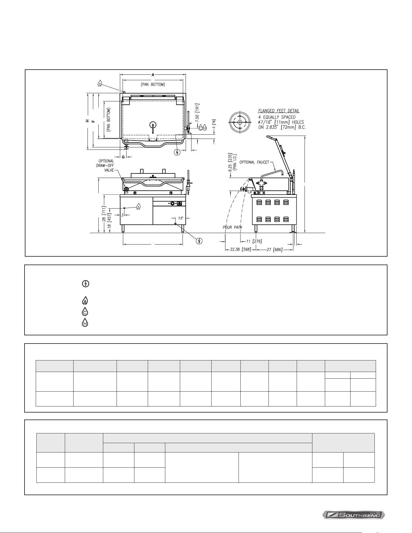
Service Connections
DIMENSIONS
As continued product improvement is a policy of Southbend Steam, specications are subject to changge without notice.
GAS CHARACTERISTICS
* For use on non-combustible floors only.
Model
Shipping
Weight
Gas Supply
Minimum Clearance *
BTU/HR kW/HR Supply Pipe Pressure (W.C)
BGMTS-30
550 lbs.
[249 kg]
80,000 23.4
Natural
6” - 14”
(152 mm - 356 mm)
Propane
11” - 14”
(279 mm - 356 mm)
Sides
3”
(76 mm)
BGMTS-40
736 lbs.
[334 kg]
100,000 29.3 Back
6”
(152 mm)
33.25 (845)
40.50 (1029)
3.75 (95)
2.38 (60)
D
B
E
C
SERVICE CONNECTIONS
–
ELECTRICAL CONNECTIONS: Unless otherwise specied, Field Wire Electrical Connection to be
120 Volts, 60 Hz, single phase with grounding wire. 10 Amp minimum supply.
- GAS CONNECTION: 3/4” IPS. A gas shut-o valve is installed in supply piping.
- COLD WATER: 3/8” O.D. tubing to faucet (OPTIONAL)
– HOT WATER: 3/8” O.D. tubing to optional faucet (OPTIONAL)
Model Capacity A B C D E F G H
BGMTS-30
30 Gallons
(114 liters)
36”
(914 mm)
30”
(762 mm)
72.38”
(1838 mm)
33.75”
(857 mm)
23.5”
(597 mm)
40”
(1016 mm)
3.75”
(95 mm)
Ø2 Ø3
42.63”
(1083 mm)
46.5”
(1181 mm)
BGMTS-40
40 Gallons
(152 liters)
48”
(1219 mm)
42”
(1067 mm)
71.75”
(1822 mm)
43.75”
(1111 mm)
23”
(584 mm)
40.38”
(1026 mm)
4.75”
(121 mm)
42.63”
(1083 mm)
46.5”
(1181 mm)
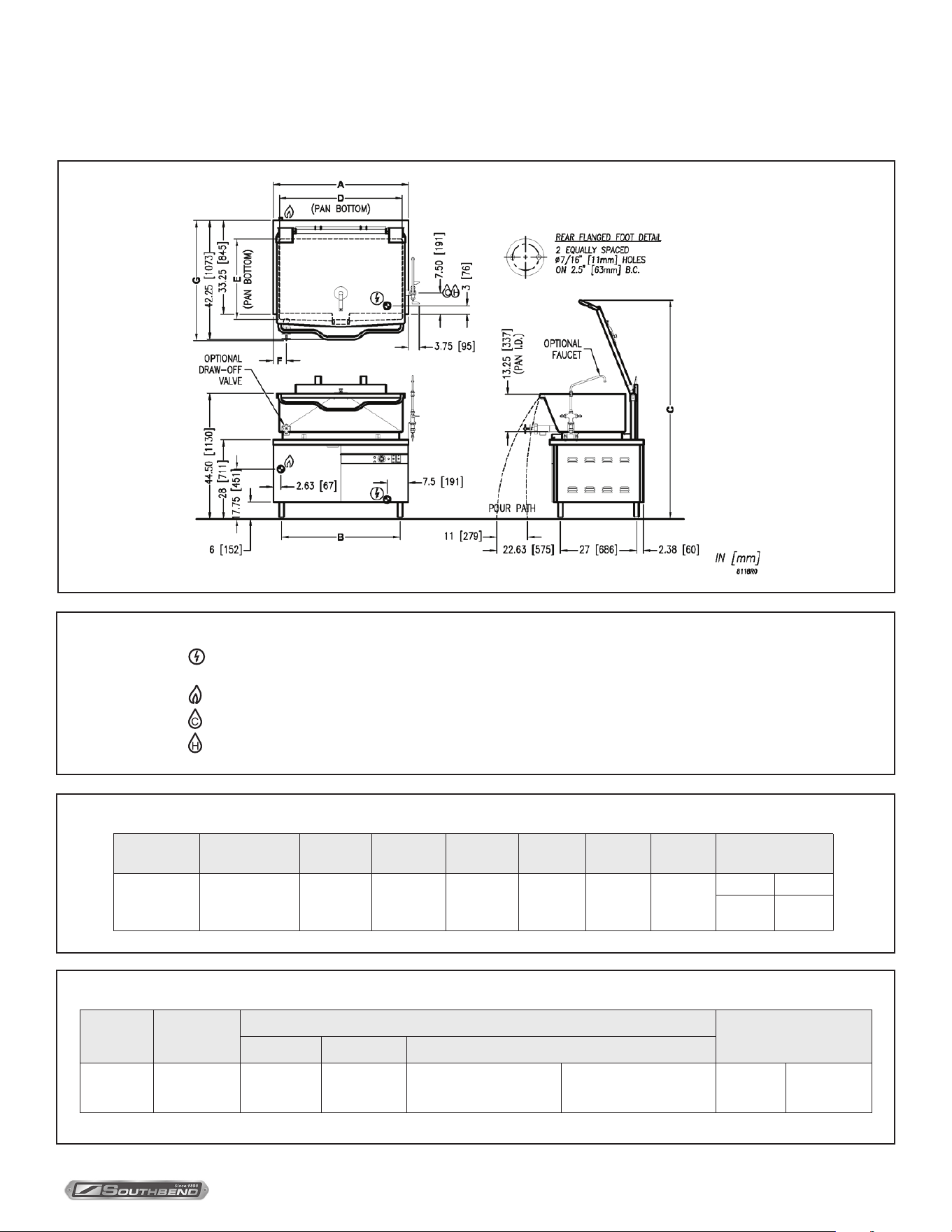
INSTALLATION & OPERATION MANUAL 10094-SB REV 0 (08/21)
PAGE
5
OF24
Gas Skillets
As continued product improvement is a policy of Southbend Steam, specications are subject to changge without notice.
DIMENSIONS
GAS CHARACTERISTICS
* For use on non-combustible floors only.
Service Connections
SERVICE CONNECTIONS
–
ELECTRICAL CONNECTIONS: Unless otherwise specied, Field Wire Electrical Connection to be
120 Volts, 60 Hz, single phase with grounding wire. 10 Amp minimum supply.
- GAS CONNECTION: 3/4” IPS. A gas shut-o valve is installed in supply piping.
- COLD WATER: 3/8” O.D. tubing to faucet (OPTIONAL)
– HOT WATER: 3/8” O.D. tubing to optional faucet (OPTIONAL)
Model Capacity A B C D E F G
BGMTS-60
60 Gallons
(227 liters)
48”
(1219 mm)
42”
(1067 mm)
77.50”
(1969 mm)
42.88”
(1089 mm)
23”
(584 mm)
4.75”
(121 mm)
Ø2 Ø3
42.63”
(1083 mm)
46.5”
(1181 mm)
Model
Shipping
Weight
Gas Supply
Minimum Clearance *
BTU/HR kW/HR Supply Pipe Pressure (W.C)
BGMTS-60
925 lbs.
[420 kg]
100,000 29.3
Natural
6” - 14”
(152 mm - 356 mm)
Propane
11” - 14”
(279 mm - 356 mm)
Side
Back
3”[ 76 mm ]
6”[152 mm]

INSTALLATION & OPERATION MANUAL 10094-SB REV 0 (08/21)
PAGE
6
OF 24
Gas Skillets
UNPACKING
IMMEDIATELY INSPECT FOR SHIPPING DAMAGE
Immediately after unpacking the appliance, check for possible shipping damage. If the gas red tilting skillet is found to
be damaged, save the packaging material and contact the carrier within 15 days of delivery.
Prior to installation, verify that the type of gas supply (natural or propane) and electrical service agree with the
specications on the rating plate located on the left side panel as you face the front of the appliance. If the supply and
equipment requirements do not agree, contact your dealer immediately.
Installation Instructions
Installation
Installation Codes and Standards
Installation must conform with local codes, or in the absence of local codes, with the National Fuel Gas Code,
ANSI Z223.1INFPA 54, or the Natural Gas and Propane Installation Code, CSA B149.1, as applicable.
1. The appliance and its individual shut o valve must be disconnected from the gas supply piping system during any
pressure testing of that system at pressures in excess of 1/2 psi (3.5 kPa).
2. The appliance must be isolated from the gas supply piping system by closing its individual manual shut o valve
during any pressure testing of the gas supply piping system at test pressures equal to or less than 1/2 psi (3.5 kPa).
Electrical grounding must be provided in accordance with local codes, or in the absence of local codes, with the National
Electrical Code, ANSI/NFPA 70, or the Canadian Electrical Code, CSA C22.2, as applicable.
Ventilation must be provided in accordance with local codes, or in the absence of local codes, with ANSI/NFPA 96 Standard
for Ventilation and Fire Protection of Commercial Cooking Operations.
Location
The installation location must allow adequate clearances for servicing and proper operation.
An exhaust system and ventilation hood should be located directly above the appliance to exhaust combustion gases
generated by the unit.
Appliance is intended for use on noncombustible oors. Minimum clearance from combustible and noncombustible oor
construction, 3” (76 mm) on sides and 6” (152 mm) from back.
Leveling and Anchoring Tilting Braising Pan
1. Place tilting braising pan in the installation position.
2. Place a carpenter’s level on top of the braising pan and turn the adjustable feet to level braising pan side-to-side and
front-to-back.
3. Mark hole locations on the oor through the anchoring holes provided in the rear anged adjustable feet.
4. Remove tilting braising pan from installation position and drill holes in locations marked on the oor. (See installation
diagram on page 4.) Insert proper anchoring devices (not supplied).
5. Place tilting braising pan back in the installation position.
6. Place carpenter’s level on top of braising pan and re-level side-to-side and front to back.
7. Bolt and anchor tilting braising pan securely to the oor.
8. Seal bolts and anged feet with silastic or equivalent compound.
INSTALLATION & OPERATION MANUAL 10094-SB REV 0 (08/21)
PAGE
7
OF24
Gas Skillets Installation
Gas Connections
WARNING
Do not connect the appliance to the electrical supply until after the gas connection has been made.
All gas supply connections and any pipe joint compound used must be resistant to the action of propane gases.
Connect gas supply to the appliance. The gas supply line must be at least equivalent of 3/4” iron pipe with an incoming
pressure of 7” - 14” W.C. (Water Column) for natural gas or 11” - 14” W.C. (Water Column) for propane gas. Make sure the
pipes are clean and free of obstructions, dirt and piping compound.
Codes require that a gas shuto valve be installed in the gas line ahead of the tilting braising pan.
Natural gas and propane gas skillets are equipped with xed orices and no adjustment is necessary. Gas burner
manifold is set at 3.5” W.C. (Water Column) for natural gas, and 10” W.C. (Water Column) for propane gas.
After piping has been checked for leaks, all piping receiving gas should be fully purged to remove air.
Electrical Connection
WARNING
Never use an open ame to check for gas leaks. Check all connections for leaks using soapy water before use.
CAUTION
The pipe thread compound used when installing pipes must be a type that is resistant to the action of liquied
petroleum or propane gases.
WARNING
ELECTRICAL GROUNDING INSTRUCTIONS
This appliance is equipped with a three-prong (grounding) plug for your protection against shock hazard
and should be plugged directly into a properly grounded three-prong receptacle. Do not cut or remove the
grounding prong from this plug. (120V units only).
The wiring compartment is located behind the control panel. For units operated on electrical supply other than 120 volts,
remove the wiring compartment cover and make electrical connections per the wiring diagram located inside the control
housing cover panel. The braising pan must be grounded in accordance with requirements of the National Electrical Code
or applicable local code.
Replace wiring compartment cover.
NOTICE
If this equipment is being installed at over 2,000 feet altitude and was not so specied on order, contact service department.
Failure to install with proper orice sizing may void the warranty.
WARNING
Do not connect the appliance to the electrical supply until after the gas connection has been made.

INSTALLATION & OPERATION MANUAL 10094-SB REV 0 (08/21)
PAGE
8
OF 24
Gas SkilletsOperation
Operating Instructions
WARNING
In the event of main burner ignition failure, a 5 minute purge period must be observed prior to re-establishing ignition source.
WARNING
The tilting braising pan and its parts are hot. Use care when operating, cleaning and servicing the tilting braising pan.
Before First Use
Using a non-corrosive, grease-dissolving commercial cleaner, clean the protective metal oils from all surface parts and the
interior of the tilting braising pan. Follow the cleaner manufacturer’s directions. Rinse thoroughly and drain the pan. Wipe
dry with a soft clean cloth.
Controls
POWER SWITCH (ON/OFF) .... Turn ON to supply power to the braising pan burner ignition system.
TILT SWITCH (UP/DOWN) ....... Push up to raise tilting braising pan; push down to lower tilting braising pan.
MOTOR SWITCH ...................... Push up to turn power on to the lift motor; push down to turn power o.
Note: It is not necessary to have the power on when using the braising pan. Turn power
on only when you intend to operate the tilt feature. This will save energy as well as
prevent the motor from overheating.
GREEN IGNITION LIGHT ......... Will light when ignition has occurred.
RED TEMPERATURE LIGHT .. Will light when heating elements are supplying heat to the tilting braising pan.
THERMOSTAT .......................... When turned on, will initiate electronic ignition system. Temperature settings range from 1 to 10.
(See COOKING GUIDELINES in this manual for temperature ranges for settings 1-10.)
Start-Up Procedure
1. Open the manual gas shut-o valve located inside cabinet on left side when facing the front of the unit.
2. Ensure that the skillet pan is in the down or horizontal position.
3. Turn the “POWER” switch “ON”.
4. Set the thermostat dial to the desired setting. The red “TEMPERATURE” pilot will be on until the desired setting has
been reached.
5. The green “IGNITION” pilot should remain on with the “TEMPERATURE” pilot, indicating normal ignition and
operation. If the “IGNITION” pilot goes o while the “TEMPERATURE” pilot remains on, this indicates that the system
has failed to ignite the burners. A ve minute period of complete shut o is required before restarting;
6. When the skillet has reached the setting, both pilots will go o, indicating the unit has reached the set temperature
and that the burners are o. The unit will cycle on and o to maintain the set temperature.
7. Turn the “POWER” switch to “OFF” when the skillet is not in use and close the manual gas shut-o valve.
INSTALLATION & OPERATION MANUAL 10094-SB REV 0 (08/21)
PAGE
9
OF24
Gas Skillets Operation
Daily Shutdown Procedure
1. To turn tilting braising pan of, turn THERMOSTAT dial to OFF.
2. To turn power to tilt motor OFF, turn power switch to OFF.
Tilting the Braising Pan
1. DO NOT try to tilt braising pan with lid down. Turn MOTOR switch on.
2. Make sure the receiving pan is in place.
3. To tilt braising pan, push and hold TILT SWITCH in the UP mode until desired pan position has been reached. The
braising pan will empty when raised to the top tilt position.
When the braising pan is raised 5 or more, the gas supply will be turned o automatically. The braising pan will not
operate when the pan is not in the horizontal or down position.
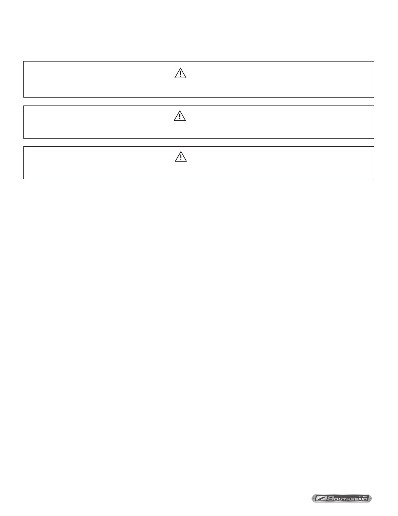
4. Food is poured through the removable strainer (Figure 1) into a food receiving pan positioned under the lip of the
pouring spout (Figure 1).
5. To lower braising pan, push and hold TILT SWITCH in the DOWN mode.
When tilting mechanism is not in use, turn MOTOR switch o.
FIGURE 1
INSTALLATION & OPERATION MANUAL 10094-SB REV 0 (08/21)
PAGE
10
OF 24
Gas SkilletsCleaning
Cleaning
WARNING
Disconnect the power supply to the appliance before cleaning or servicing.
After each use, allow the tilting braising pan to cool before cleaning. Keep exposed cleanable areas of the tilting braising
pan clean at all times. Do not get water in electrical box or on any electrical component.
1. Thoroughly wash pan, pouring spout, lid and exterior surfaces with mild detergent and warm water. If necessary, soak
pan to remove food that is stuck to pan surface. Rinse thoroughly and wipe dry with a soft clean cloth.
2. Clean removable strainer and receiving pan support with mild detergent and warm water. Rinse thoroughly and wipe dry
with a soft clean cloth.
3. Clean around burner air mixer and orice if lint has accumulated.
4. Visually assure carry-over ports are unobstructed.
WARNING
The appliance and its parts are hot. Use care when operating, cleaning and servicing the skillet.
CAUTION
Do not use cleaning agents that are corrosive.

INSTALLATION & OPERATION MANUAL 10094-SB REV 0 (08/21)
PAGE
11
OF24
Gas Skillets
Cooking Guidelines
Cooking Method Temperature (°F) Thermostat Setting
Simmering 200 Maximum 1 - 4
Sautéing 225 - 275 5 - 6
Searing 300 - 350 7 - 8
Frying 325 - 375 8 - 9
Grilling 350 - 450 9 - 10
INSTALLATION & OPERATION MANUAL 10094-SB REV 0 (08/21)
PAGE
12
OF 24
Gas SkilletsMaintenance
Maintenance
NOTICE
Contact the factory, factory representative or local service company to perform maintenance and repairs.
WARNING
Disconnect the power supply to the appliance before cleaning or servicing.
WARNING
The tilting braising pan and its parts are hot. Use care when operating, cleaning and servicing the tilting braising pan.
Hydraulic System
Service
Set up regular schedule for checking the oil temperature, hydraulic hoses and keeping the equipment clean. A thick layer
of dirt acts as an insulation and prevents the hydraulic system from getting rid of heat.
The hydraulic system has been adjusted and tested at the factory and no further adjustment should be needed. If the unit
fails to operate properly, all service work must be performed by a qualied service agent.
1. Hot oil in the Hydraulic System is one of the primary causes of poor operation. When the tilt system is not in use turn
MOTOR switch o.
2. Inspect hydraulic hoses for wear and aging.
3. Check that uid levels are kept full.
4. To replace oil, ll through ller breather.
5. Use proper oil as specied by factory or equivalent.
6. Check the cleanliness of the oil strainer inside the reservoir once per year. This item can be washed in clean Varsol.
7. Change the breather lter once per year.
8. Change the oil once every two years.
Adjustments and Controls
Adjust Pan Speed
There are three controls available on this power unit. The rst is an adjustable relief valve mounted into the custom
aluminum manifold block. The other two control the linear speed of the actuator.

INSTALLATION & OPERATION MANUAL 10094-SB REV 0 (08/21)
PAGE
13
OF24
Gas Skillets Maintenance
Relief Valve
The relief valve is located underneath an aluminum hexagon cover on the side of the custom manifold block. This relief
valve is factory set to 825 P.S.I. and locked and should not be adjusted.
If adjustments are necessary, remove the hexagon cover which will give access to the relief valve screw. With the
pump running, and with a suitable at blade style screwdriver, rotate the screw clockwise to increase pressure, and
anti clockwise to decrease pressure. While this operation is being carried out some oil will leak down the threads of the
adjusting screw.
To obtain the pressure required, a pressure gauge will have to be located in the circuit. The best location is on the
cylinder hose. To set the pressure, energize the solenoid to extend the cylinder fully and thus “deadhead” the system. The
pressure can be set as indicated above. When adjustment is complete, replace the hexagon cover. This will seal the relief
valve area. The actual factory set pressure is noted on the label and should not be exceeded as this aects the HP draw
on the electric motor.
Flow Control
!
IMPORTANT !
It should be noted that if the cylinder speed is restricted by the ow control valves, the balance of oil not
delivered to the cylinder will go over the relief @ 825 P.S.I. which will cause unwanted heat in the reservoir.
There are two ow control valves mounted on the power unit and located on the solenoid valve subplate. The ow
control valves will restrict the capacity of oil passing through them when the knurled knob is screwed in - in a clockwise
direction. This action will reduce the linear speed of the cylinder. Turning the ow control valve adjustment in the opposite
direction - anti clockwise, will increase the speed of the cylinder. One ow control valve (right side) will allow adjustment
of the extension speed (travel speed should be set at minimum 20 seconds), the other (left side) the retraction speed.
(Retraction speed should be set at minimum 10 seconds).

INSTALLATION & OPERATION MANUAL 10094-SB REV 0 (08/21)
PAGE
14
OF 24
Gas SkilletsTroubleshooting
Troubleshooting
Burners No Not Come On
1. Gas supply to unit is “OFF”.
2. Manual shut o valve is “OFF”.
3. Thermostat is not turned “ON”.
4. Pan not in lowest position.
5. Ignition control not functioning.
Burners Produce Carbon Deposits
1. Wrong size orices.
2. Burner air not adjusted properly.
3. Wrong gas supply.
4. Incorrect pressure at supply.
Braising Pan Will Not Operate (Up or Down)
1. Motor power supply not “ON”.
2. Defective UP/DOWN switch.
3. SEE TROUBLESHOOTING - HYDRAULICS.
Troubleshooting - Hydraulics
Dirty Oil
1. Components not properly cleaned after servicing.
2. Inadequate screening in ll pipe.
3. Air breather left o.
4. Filter dirty or ruptured.
Foaming Oil
1. Return of tank line not below uid level.
2. Fluid contamination.
3. Suction leak to pump.
Moisture in Oil
1. Fill pipes left open.
2. Moisture in cans used to replace oil in tank.
3. Extreme temperature dierential.

INSTALLATION & OPERATION MANUAL 10094-SB REV 0 (08/21)
PAGE
15
OF24
Gas Skillets
Overheating of System
1. Continuous operation at relief setting.
2. Excessive slippage or internal leakage.
3. Fluid viscosity too high or low.
4. Hose I.D. too small causing high velocity.
5. Improper air circulation around reservoir.
6. System relief valve set too high.
7. Power unit operating in direct sunlight or ambient temperature is too high.
Pump Makes Excessive Noise
1. Check for vacuum leaks in suction line.
2. Vacuum leak at pump shaft seal.
3. Check alignment with drive mechanism. Misalignment will cause wear and subsequent high noise level operation.
4. Relief valve set too high.
5. Aeration of uids in reservoir (return line above uid level.)
6. Worn cam ring, damaged gear, faulty bearing.
7. Reversed rotation.
8. Plugged lines.
9. Oil viscosity too high or temperature too low.
10. Loose or worn pump parts.
11. Pump housing bolts loose or not properly torqued.
Solenoid Valves
1. Voltage too low.
2. Short circuit, open connection.
3. Wrong voltage.
4. Foreign matter in uid causing valves to stick or plug.
Troubleshooting
INSTALLATION & OPERATION MANUAL 10094-SB REV 0 (08/21)
PAGE
16
OF 24
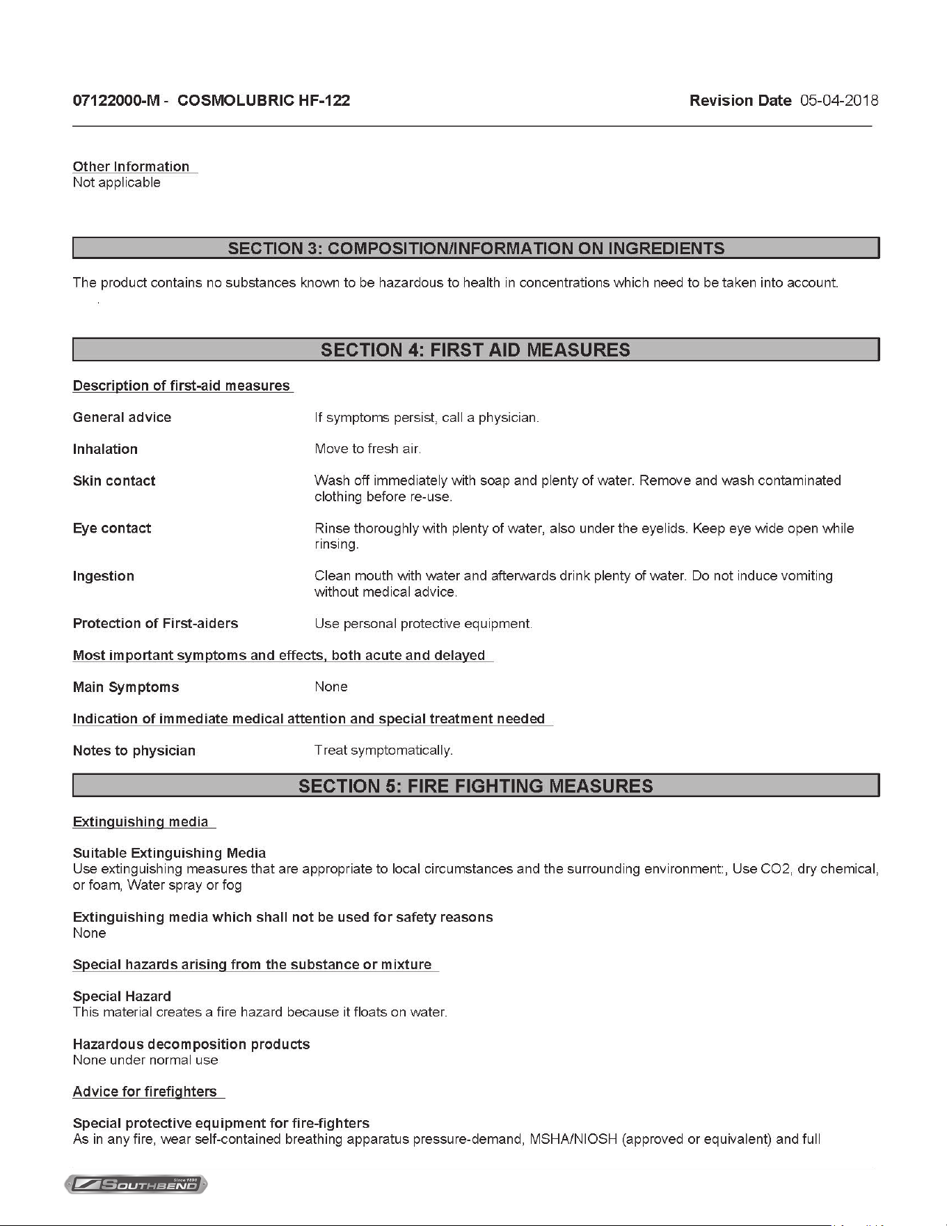
Gas SkilletsMaterial Safety Data Sheets
INSTALLATION & OPERATION MANUAL 10094-SB REV 0 (08/21)
PAGE
17
OF24
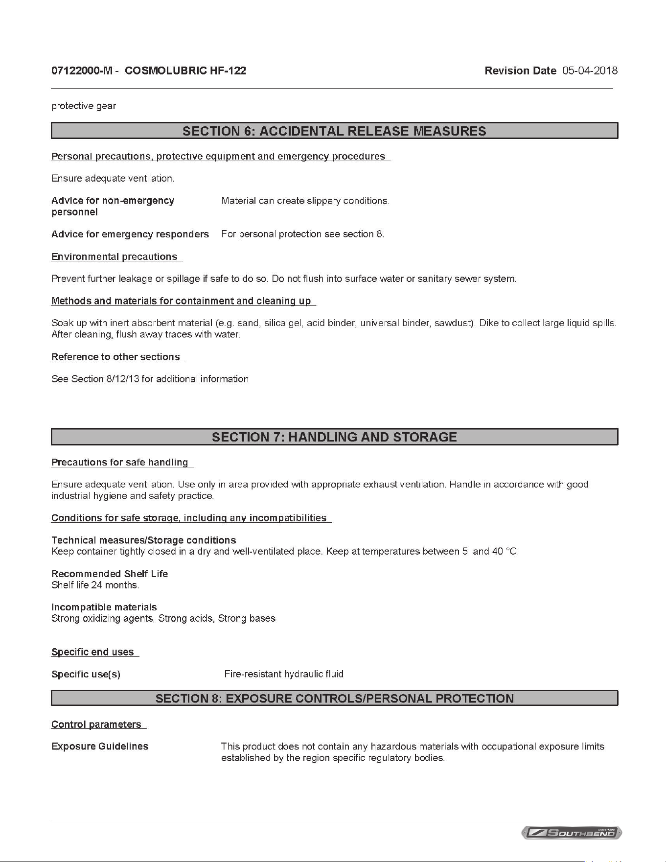
Gas Skillets Material Safety Data Sheets
INSTALLATION & OPERATION MANUAL 10094-SB REV 0 (08/21)
PAGE
18
OF 24
Gas SkilletsMaterial Safety Data Sheets
INSTALLATION & OPERATION MANUAL 10094-SB REV 0 (08/21)
PAGE
19
OF24
Gas Skillets Material Safety Data Sheets
INSTALLATION & OPERATION MANUAL 10094-SB REV 0 (08/21)
PAGE
20
OF 24
Gas SkilletsMaterial Safety Data Sheets
INSTALLATION & OPERATION MANUAL 10094-SB REV 0 (08/21)
PAGE
21
OF24
Gas Skillets Material Safety Data Sheets
INSTALLATION & OPERATION MANUAL 10094-SB REV 0 (08/21)
PAGE
22
OF 24
Gas SkilletsMaterial Safety Data Sheets
INSTALLATION & OPERATION MANUAL 10094-SB REV 0 (08/21)
PAGE
23
OF24
Gas Skillets Material Safety Data Sheets
INSTALLATION & OPERATION MANUAL 10094-SB REV 0 (08/21)
PAGE
24
OF 24
Gas Skillets
BGMTS-30, BGMTS-40 & BGMTS-60
Gas Skillets
A product with the Southbend Steam name incorporates the best in durability and low maintenance. We all recognize,
however, that replacement parts and occasional professional service may be necessary to extend the useful life of this
appliance. When service is needed, contact a Southbend Steam Authorized Service Agency, or your dealer. To avoid
confusion, always refer to the model number, serial number, and type of your appliance.
SOUTHBEND STEAM
A Middleby Company
1100 Old Honeycutt Road Fuquay-Varina, North Carolina 27526 USA
www.southbendnc.com

