MANUAL 10152-SB REV 1 (05/22)
$21.00
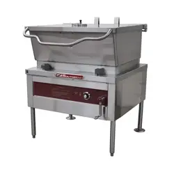
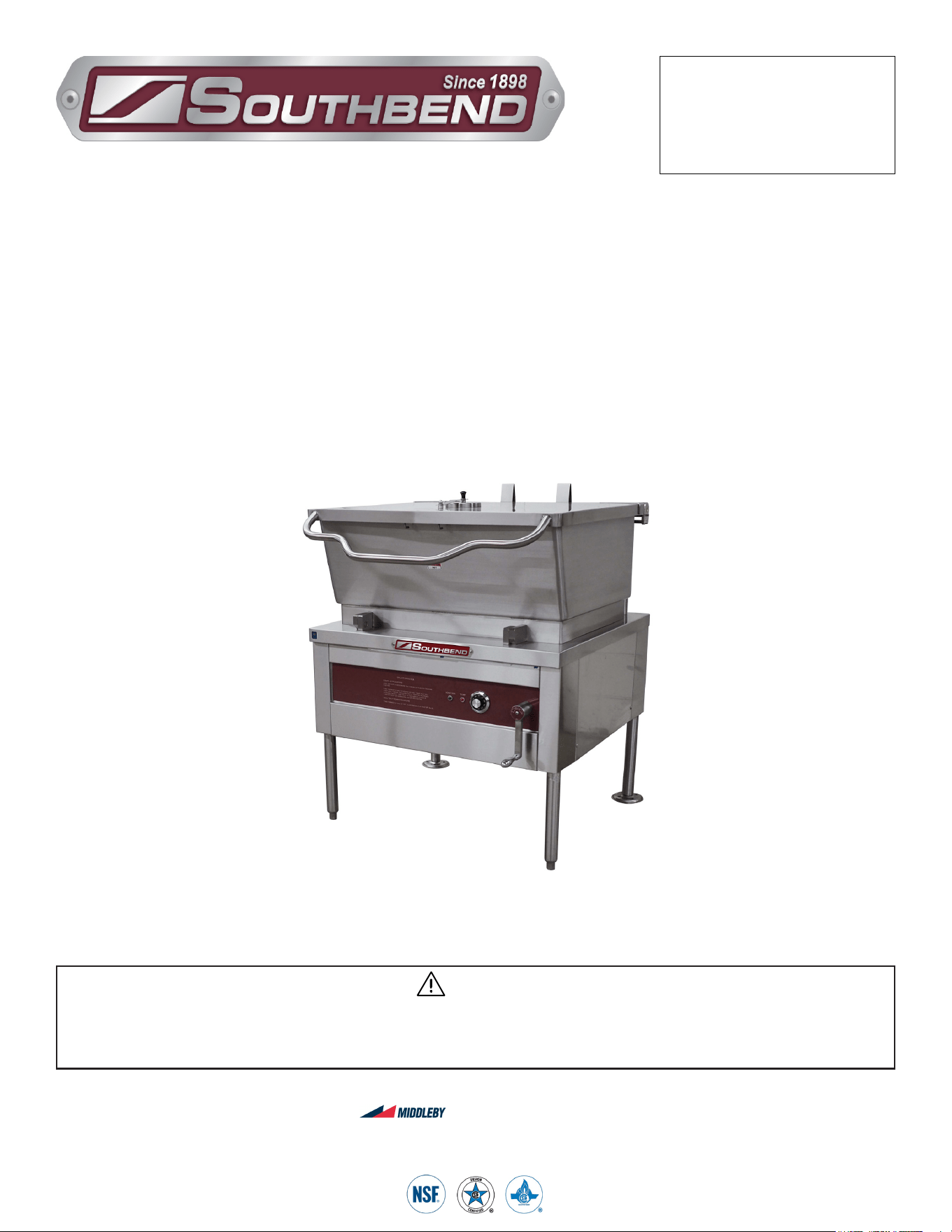
Gas Floor Model Braising Pan
with Manual Gearbox Tilt
MANUAL SECTION CO
IMPORTANT FOR FUTURE REFERENCE
Please complete this information and retain this
manual for the life of the equipment:
Model #:
___________________________
Serial #:
___________________________
Date Purchased:
_____________________
WARNING
Improper installation, adjustment, alteration, service or maintenance can cause property damage, injury
or death. Read the installation, operating and maintenance instructions thoroughly before installing or
servicing this equipment.
Gas Floor Model Braising Pan
With Manual Gearbox Tilt
BGLM-30, BGLM-40, BGLM-40N
and BGLM-60
Installation & Operation Manual
Model BGLM-40N
SOUTHBEND STEAM
A Middleby Company
1100 Old Honeycutt Road Fuquay-Varina, North Carolina 27526 USA
www.southbendnc.com
INSTALLATION & OPERATION MANUAL 10152-SB REV 1 (05/22)
PAGE
2
OF 20
Gas Floor Model Braising Pan With Manual Gearbox Tilt
SAFETY PRECAUTIONS
Before installing and operating this equipment, be sure everyone involved in its operation is fully trained and aware of
precautions. Accidents and problems can be caused by failure to follow fundamental rules and precautions.
The following symbols, found throughout this manual, alert you to potentially dangerous conditions to the operator,
service personnel, or to the equipment.
CAUTION
WARNING
NOTICE
This symbol warns of immediate hazards that will result in severe injury or death.
This symbol refers to a potential hazard or unsafe practice that could result in injury or death.
This symbol refers to a potential hazard or unsafe practice that could result in injury, product
damage, or property damage.
This symbol refers to information that needs special attention or must be fully
understood, even though not dangerous.
DANGER
WARNING
Improper installation, operation, adjustment, alteration, service or maintenance can cause property damage, injury
or death. Read the installation, operating and maintenance instructions thoroughly before installing, operating or
servicing this equipment.
NOTICE
This manual should be retained for future reference.
NOTICE
This product is intended for commercial use only. NOT FOR HOUSEHOLD USE.
Copyright © 2021 by Southbend Steam. All rights reserved. Published in the United States of America.
SPECIFICATIONS
IMPORTANT NOTES FOR INSTALLATION AND OPERATION
WARNING
This is the safety alert symbol. It is used to alert you to potential personal injury hazards. Obey all safety messages
that follow this symbol to avoid possible injury or death.
WARNING
FOR YOUR SAFETY:
Do not store or use gasoline or other ammable vapors or liquids in the vicinity of this or any other appliance.
PURCHASER: Instructions to be followed in the event the operator of this appliance smells gas must be posted
in a prominent location. This information shall be obtained by consulting the local gas supplier.
Keep the appliance area free and clear from combustibles.
DO NOT obstruct the ow of combustion and ventilation air.
Adequate clearances MUST be maintained for servicing and proper operation.
Contact the factory, the factory representative or a local service company to perform maintenance and repairs
should the appliance malfunction. Refer to warranty terms.

INSTALLATION & OPERATION MANUAL 10152-SB REV 1 (05/22)
PAGE
3
OF20
Gas Floor Model Braising Pan With Manual Gearbox Tilt
RETAIN THIS MANUAL FOR FUTURE REFERENCE.
Table of Contents
Important Notes For Installation and Operation .................................................................... 2
Service Connections ............................................................................................................. 4
Installation Instructions ......................................................................................................... 8
Operation .............................................................................................................................. 10
Preventive Maintenance ....................................................................................................... 12
Cooking Guidelines ............................................................................................................... 13
Troubleshooting .................................................................................................................... 16
Table of Contents
INSTALLATION & OPERATION MANUAL 10152-SB REV 1 (05/22)
PAGE
4
OF 20
Gas Floor Model Braising Pan With Manual Gearbox Tilt
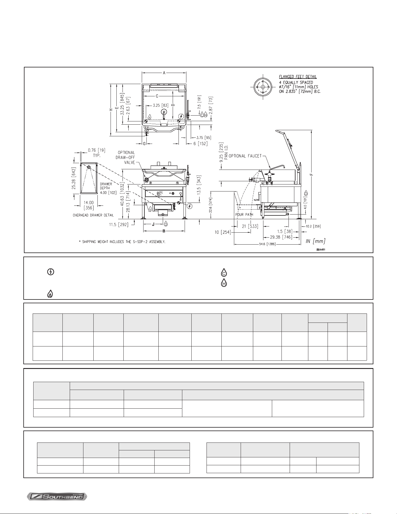
SERVICE CONNECTIONS
SERVICE CONNECTIONS
SPECIFICATIONS
GAS CHARACTERISTICS
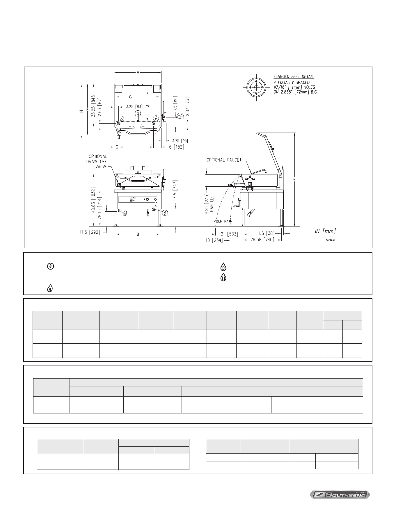
DIMENSIONS
* For use on non-combustible floors only.
–
Unless otherwise specied unit is furnished with 6’ cord
with 3 prong plug for use at 120 Volts, 60 Hz, single phase,
maximum 2 Amps.
–
GAS CONNECTION: 3/4” IPS
Model
Gas Supply
BTU/HR kW/HR Supply Pipe Pressure (W.C)
BGLM-30 100,000 29.3
Natural
6” - 14” (152 mm - 356 mm)
Propane
11” - 14” (279 mm - 356 mm)
BGLM-40 125,000 36.6
Model Shipping Weight Minimum Clearance *
BGLM-30 550 lbs. [250 kg] Sides 0
BGLM-40 720 lbs. [327 kg] Back 6” (152 mm)
Model Capacity A B C D E F G
H
Ø2 Ø3
BGLM-30
30 Gallons
(114 liters)
36”
(914 mm)
33.63”
(854 mm)
33.5”
(851 mm)
23.5”
(597 mm)
39.5”
(1003 mm)
72.38"
(1838 mm)
3.75"
(95 mm)
41.13
(1045)
46.75
(1187)
BGLM-40
40 Gallons
(152 liters)
48”
(1219 mm)
45.63”
(1159 mm)
43.5”
(1105 mm)
23”
(584 mm)
39.88”
(1000 mm)
71.88"
(1826 mm)
4.75"
(121 mm)
41.63
(1057)
46.13
(1172)
Model BTU
Capacity
Gallon Liter
BGLM-30 100,000 30 114
BGLM-40 125,000 40 152
–
COLD WATER: 3/8” O.D. tubing to optional faucet
– HOT WATER: 3/8” O.D. tubing to optional faucet
SERVICE CONNECTIONS
As continued product improvement is a policy of Southbend Steam, specications are subject to changge without notice.
INSTALLATION & OPERATION MANUAL 10152-SB REV 1 (05/22)
PAGE
5
OF20
Gas Floor Model Braising Pan With Manual Gearbox Tilt
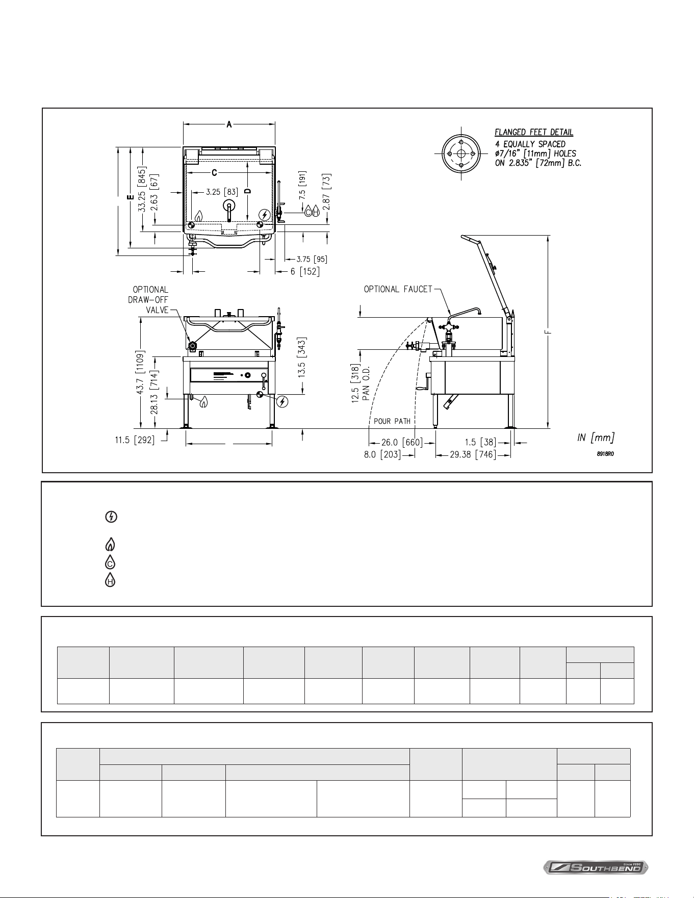
SPECIFICATIONS
GAS CHARACTERISTICS
DIMENSIONS
* For use on non-combustible floors only.
–
Unless otherwise specied unit is furnished with 6’ cord
with 3 prong plug for use at 120 Volts, 60 Hz, single phase,
maximum 2 Amps.
–
GAS CONNECTION: 3/4” IPS
Model
Gas Supply
BTU/HR kW/HR Supply Pipe Pressure (W.C)
BGLM-30 100,000 29.3
Natural
6” - 14” (152 mm - 356 mm)
Propane
11” - 14” (279 mm - 356 mm)
BGLM-40 125,000 36.6
Model Shipping Weight Minimum Clearance *
BGLM-30 590 lbs. [268 kg] Sides 0
BGLM-40 760 lbs. [345 kg] Back 6” (152 mm)
Model Capacity A B C D E F G
H
J
Ø2 Ø3
BGLM-30
30 Gallons
(114 liters)
36”
(914 mm)
33.63”
(854 mm)
33.5”
(851 mm)
23.5”
(597 mm)
39.5”
(1003 mm)
72.38"
(1838 mm)
3.75"
(95 mm)
42.63
(1083)
46.5
(1181)
15.9
(404)
BGLM-40
40 Gallons
(152 liters)
48”
(1219 mm)
45.63”
(1159 mm)
43.5”
(1105 mm)
23”
(584 mm)
39.88”
(1000 mm)
71.88"
(1826 mm)
4.75"
(121 mm)
42.63
(1083)
46.5
(1181)
22.8
(580)
Model BTU
Capacity
Gallon Liter
BGLM-30 100,000 30 114
BGLM-40 125,000 40 152
–
COLD WATER: 3/8” O.D. tubing to optional faucet
– HOT WATER: 3/8” O.D. tubing to optional faucet
SERVICE CONNECTIONS
With Optional S-SDP-2 Assembly
SERVICE CONNECTIONS
As continued product improvement is a policy of Southbend Steam, specications are subject to changge without notice.
INSTALLATION & OPERATION MANUAL 10152-SB REV 1 (05/22)
PAGE
6
OF 20
Gas Floor Model Braising Pan With Manual Gearbox Tilt
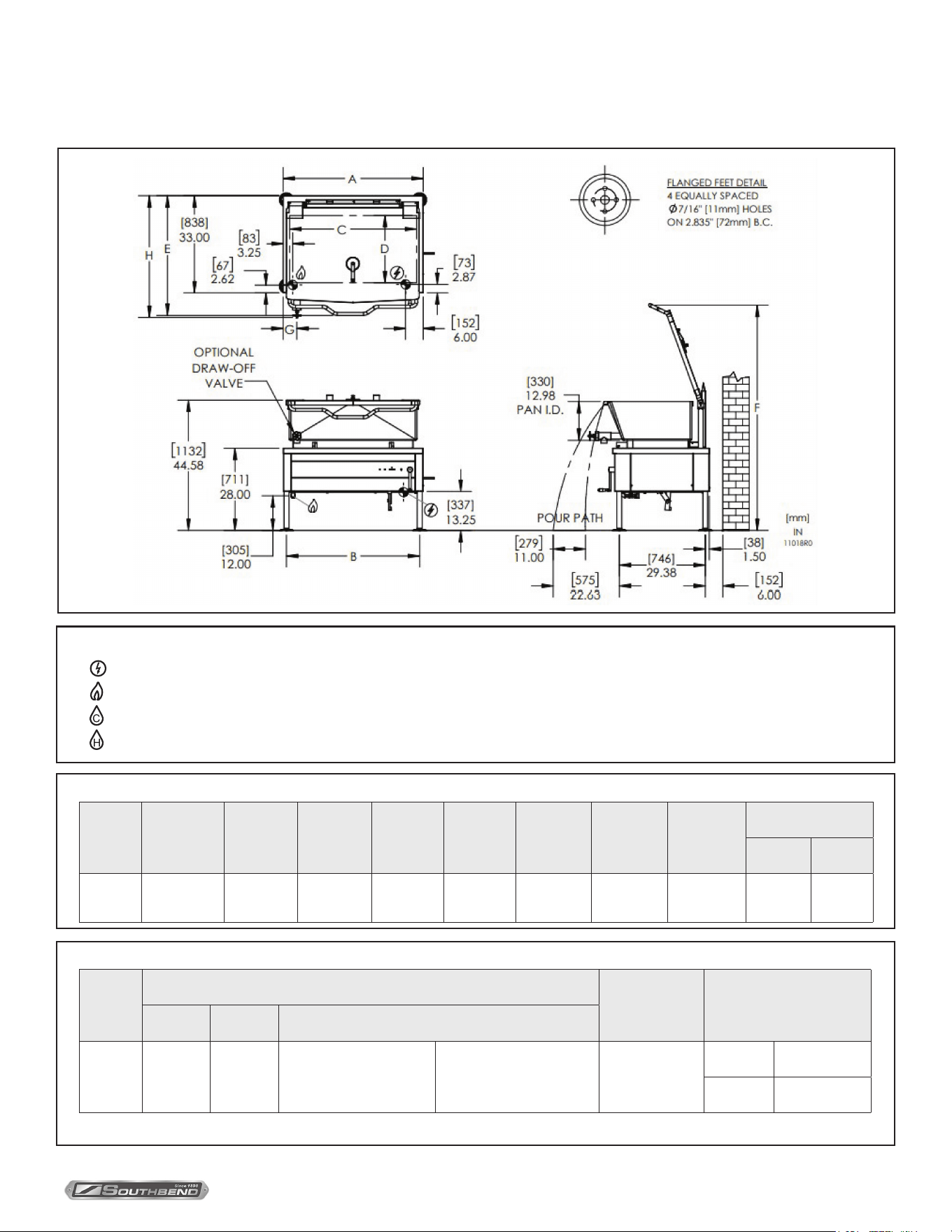
GAS CHARACTERISTICS
DIMENSIONS
* For use on non-combustible floors only.
–
Unless otherwise specied unit is furnished with 6’ cord with 3 prong plug for use at 120 Volts, 60 Hz, single phase,
maximum 2 Amps.
–
GAS CONNECTION: 3/4” IPS
–
COLD WATER: 3/8” O.D. tubing to optional faucet
– HOT WATER: 3/8” O.D. tubing to optional faucet
SERVICE CONNECTIONS
B
DIMENSIONS
SUPPLY PIPE PRESSURE (W.C.)
GS-40N
MODEL
kW/HR.BTU/HR.
GAS SUPPLY
SERVICE CONNECTIONS
MIN. CLEARANCE*
SHIPPING WT. FABCDE
inches
UNITSMODEL CAPACITY
GS-40N
GH
SKI LL ET O PERA T I O N
ST AR T UP PR OCEDURE
DAILY SHUT DO WN PROCEDURE
TO TI LT S KILLET
TEMP
H
G
Model
Gas Supply
Shipping
Weight
Minimum Clearance *
Capacity
BTU/HR kW/HR Supply Pipe Pressure (W.C) Gallon Liter
BGLM-40N 100,000 29.3
Natural
6” - 14”
(152 mm - 356 mm)
Propane
11” - 14”
(279 mm - 356 mm)
565 lbs.
[257 kg]
Sides 0
40 152
Back 6” (152 mm)
Model Capacity A B C D E F G
H
Ø2 Ø3
BGLM-40N
40 Gallons
(152 liters)
36”
(914 mm)
33.63”
(854 mm)
33.5”
(851 mm)
23.5”
(597 mm)
39.5”
(1003 mm)
75.50"
(1918 mm)
3.75"
(95 mm)
42.5
(1080)
48.13
(1222)
B
DIMENSIONS
SUPPLY PIPE PRESSURE (W.C.)
GS-40N
MODEL
kW/HR.BTU/HR.
GAS SUPPLY
SERVICE CONNECTIONS
MIN. CLEARANCE*
SHIPPING WT. FABCDE
inches
UNITSMODEL CAPACITY
GS-40N
GH
SKI LL ET O P E RA T I ON
ST AR T U P PR OCEDURE
DAILY SHUT DO WN PROCEDURE
TO TI LT S KILLET
TEMP
H
G
SERVICE CONNECTIONS
As continued product improvement is a policy of Southbend Steam, specications are subject to changge without notice.
INSTALLATION & OPERATION MANUAL 10152-SB REV 1 (05/22)
PAGE
7
OF20
Gas Floor Model Braising Pan With Manual Gearbox Tilt
GAS CHARACTERISTICS
DIMENSIONS
SERVICE CONNECTIONS
–
Unless otherwise specied unit is furnished with 6’ cord with 3 prong plug for use at 120 Volts, 60 Hz, maximum 2 Amps.
- GAS CONNECTION: 3/4” IPS
– COLD WATER: 3/8” O.D. tubing to optional faucet
– HOT WATER: 3/8” O.D. tubing to optional faucet
Model
Gas Supply
Shipping Weight Minimum Clearance
BTU/HR kW/HR Supply Pipe Pressure (W.C)
BGLM-60 125,000 36.6
Natural
6” - 14” (152 mm - 356 mm)
Propane
11” - 14” (279 mm - 356 mm)
755 lbs. [342 kg]
Sides 0
Back 6” (152 mm)
Model Capacity A B C D E F G
H
Ø2 Ø3
BGLM-60
60 Gallons
(272 liters)
48”
(1219 mm)
45.63”
(1159 mm)
43.5”
(1105 mm)
23”
(584 mm)
40.88”
(1038 mm)
77.03"
(1957 mm)
4.75"
(121 mm)
41.63
(1057)
46.13
(1172)
* For use on non-combustible floors only.
As continued product improvement is a policy of Southbend Steam, specications are subject to changge without notice.

INSTALLATION & OPERATION MANUAL 10152-SB REV 1 (05/22)
PAGE
8
OF 20
Gas Floor Model Braising Pan With Manual Gearbox Tilt
UNPACKING
IMMEDIATELY INSPECT FOR SHIPPING DAMAGE
Immediately after unpacking the steamer, check for possible shipping damage. If the steamer is found to be damaged,
save the packaging material and contact the carrier within 15 days of delivery.
Before installing, verify that the type of gas supply (natural or propane) and electrical service agree with the
specications on the rating plate located on the left side panel as you face the front of the braising pan. If the supply
and equipment requirements do not agree, contact your dealer.
INSTALLATION INSTRUCTIONS
Location
The equipment must be kept free and clear of combustible substances. The tilting braising pan, when installed, must have
minimum clearance from combustible and non-combustible construction of 0” from sides and 6” (152 mm) from the rear.
The tilting braising pan is intended for use on non-combustible oors.
The installation location must allow adequate clearances for servicing and proper operation. A minimum front clearance of
36” (914 mm) is required.
The tilting braising pan must be installed so that the ow of combustion and ventilation air will not be obstructed. Adequate
clearance for air openings into the combustion chamber must be provided. Make sure there is an adequate supply of air in
the room suitable for the amount of combustion gas feeding the braising pan burners.
Do not permit fans to blow directly at the tilting braising pan, and wherever possible, avoid open windows next to the tilting
braising pan. Avoid wall-type fans which create air cross currents within the room.
Installation Codes and Standards
Installation must conform with local codes, or in the absence of local codes, with the National Fuel Gas Code, ANSI Z223.1/
NFPA 54, or the Natural Gas and Propane Installation Code, CSA B149.1, as applicable.
1. The appliance and its individual shut o valve must be disconnected from the gas supply piping system during any
pressure testing of that system at pressures in excess of 1/2 psig (3.5 kPa).
2. The appliance must be isolated from the gas supply piping system by closing its individual manual shut o valve
during any pressure testing of the gas supply piping system at test pressures equal to or less than 1/2 psig (3.5 kPa).
Electrical grounding must be provided in accordance with local codes, or in the absence of local codes, with the National
Electrical Code ANSI/NFPA 70. In Canada, installation must be in accordance with the Canadian Electrical Code CSA C22.2.
ANSI/NFPA 96 - (latest edition), “Standard for Ventilation and Fire Protection of Commercial Cooking Operations,”
available from the National Fire Protection Association, Batterymarch Park, Quincy, MA, USA, 02269.
Flue Connections
Do not obstruct the ow of ue gases from the ue duct located on the rear of the tilting braising pan. It is recommended
that the ue gases be ventilated to the outside of the building through a ventilation system installed by qualied personnel.
WARNING
ELECTRICAL GROUNDING INSTRUCTIONS
This appliance is equipped with a three-prong (grounding) plug for your protection against shock hazard
and should be plugged directly into a properly grounded three-prong receptacle. Do not cut or remove the
grounding prong from this plug. (120V units only).
INSTALLATION
INSTALLATION & OPERATION MANUAL 10152-SB REV 1 (05/22)
PAGE
9
OF20
Gas Floor Model Braising Pan With Manual Gearbox Tilt INSTALLATION
Leveling and Anchoring
1. Set the appliance in place and level left to right and front-to-back using spirit level.
2. Mark hole locations on oor through anchoring holes provided in anged adjustable feet.
3. Remove appliance and drill holes in locations marked on oor and insert proper anchoring devices (not supplied).
4. Set unit back in position and re-level left to right and front to back.
5. Bolt and anchor appliance securely to the oor.
6. Seal bolts and anged feet with Silastic or equivalent compound.
WARNING
Do not connect the appliance to the electrical supply until after the gas connection has been made.
Gas Connections
All gas supply connections and any pipe joint compound used must be resistant to the action of propane gases.
The gas inlet is located under the control panel on the left-hand side.
Connect gas supply to the tilting braising pan. The gas supply line must be at least the equivalent of 3/4” iron pipe with an
incoming pressure of approximately 7” W.C. (Water Column) for natural gas or 11” W.C. (Water Column) for propane gas.
Make sure the pipes are clean and free of obstructions, dirt and piping compound.
Codes require that a gas shuto valve be installed in the gas line ahead of the tilting braising pan.
Natural gas and propane gas braising pans are equipped with xed orices and no adjustment is necessary. Gas burner
manifold is set at 3.5” W.C. (Water Column) for natural gas, and 10” W.C. (Water Column) for propane gas.
WARNING
Never use an open ame to check for gas leaks. Check all connections for leaks using soapy water before use.
After piping has been checked for leaks, all piping receiving gas should be fully purged to remove air.
INSTALLATION & OPERATION MANUAL 10152-SB REV 1 (05/22)
PAGE
10
OF 20
Gas Floor Model Braising Pan With Manual Gearbox Tilt
Before First Use
Using a non-corrosive, grease-dissolving commercial cleaner, clean the protective metal oils from all surface parts and the
interior of the tilting braising pan. Follow the cleaner manufacturer’s directions. Rinse thoroughly and drain the pan. Wipe
dry with a soft clean cloth.
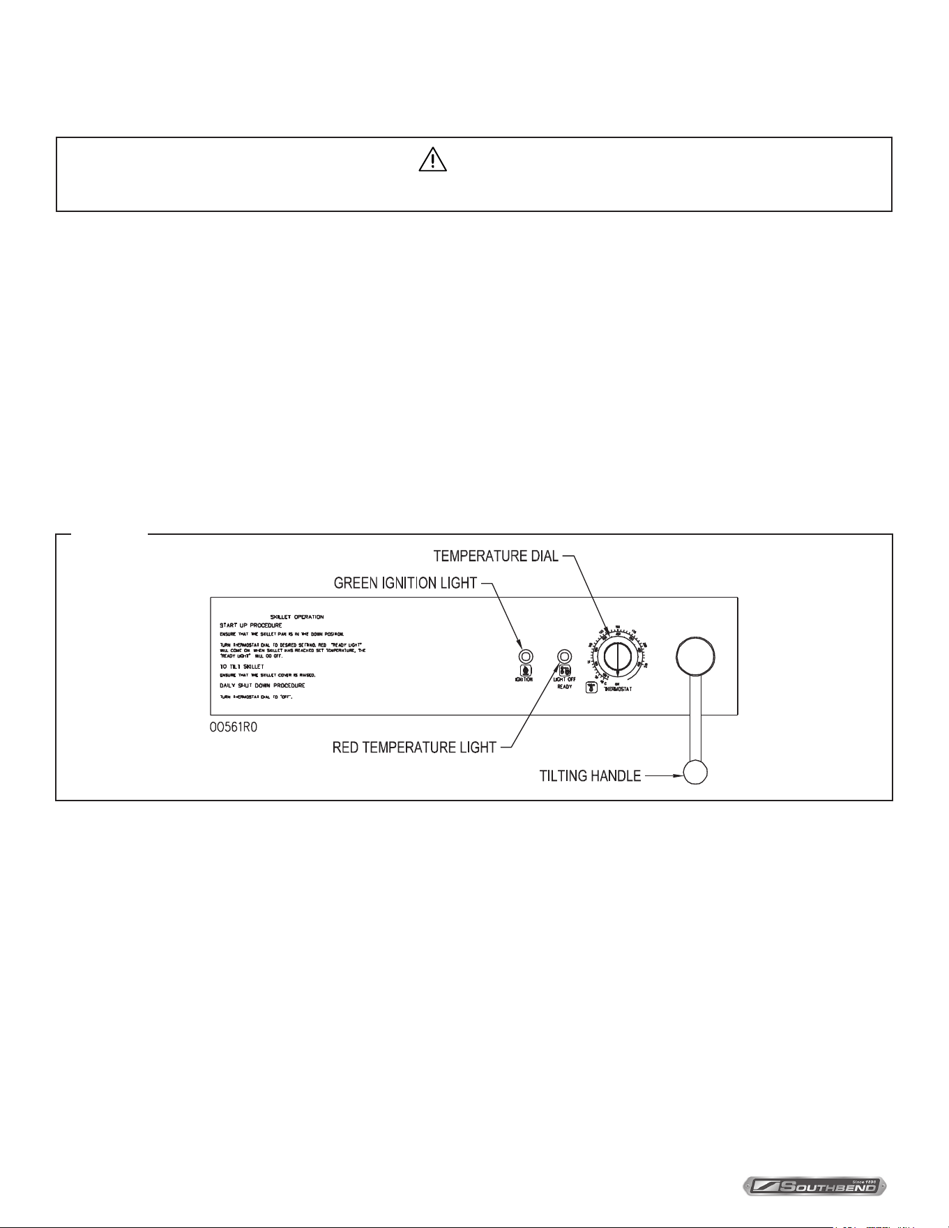
CONTROLS (figure 1)
Green Ignition Light ............. Will light when ignition has occurred.
Red Temperature Light ........ Will light when burners are supplying heat to the tilting braising pan.
Thermostat ............................ When turned ON, will initiate electronic ignition system. Temperature settings are marked
on the control panel in C and F.
Manual Lift Crank Handle .... Used to manually raise and lower braising pan.
Figure 1
Start-up Procedure
1. Open manual gas shuto valve.
2. Ensure that the braising pan is in the DOWN position.
3. Turn THERMOSTAT dial to desired setting. The red TEMPERATURE LIGHT will come on. This will turn on the
electronic ignition which will light the burners.
4. If the green IGNITION LIGHT does not come on after 90 seconds, turn THERMOSTAT OFF and then ON again for
restart.
5. When braising pan has reached set temperature, the red TEMPERATURE LIGHT will go o and the burners will shut
o. The burners will cycle on and o thereafter to maintain set temperature. The red TEMPERATURE LIGHT will be
on when the burners are on and o when burners are o.
6. If gas supply is interrupted during operation, turn THERMOSTAT dial to OFF position and turn gas supply OFF. Wait 5
minutes, then repeat Steps 1 through 4 to restart.
7. Turn THERMOSTAT to OFF when braising pan is not in use.
OPERATION
CAUTION
The appliance and its parts are hot. Use care when operating, cleaning and servicing the appliance.
OPERATION
INSTALLATION & OPERATION MANUAL 10152-SB REV 1 (05/22)
PAGE
11
OF20
Gas Floor Model Braising Pan With Manual Gearbox Tilt OPERATION
Daily Shutdown Procedure
Turn THERMOSTAT dial to OFF. Close manual gas shuto valve.
Tilting the Braising Pan
1. DO NOT try to tilt braising pan with lid down.
2. Make sure the receiving pan is in place.
3. Turn crank handle clockwise to lift the braising pan and counterclockwise to lower the braising pan. When the braising
pan is raised 5° or more, the gas supply will be turned o automatically. The braising pan will not operate once the
pan has been tilted.
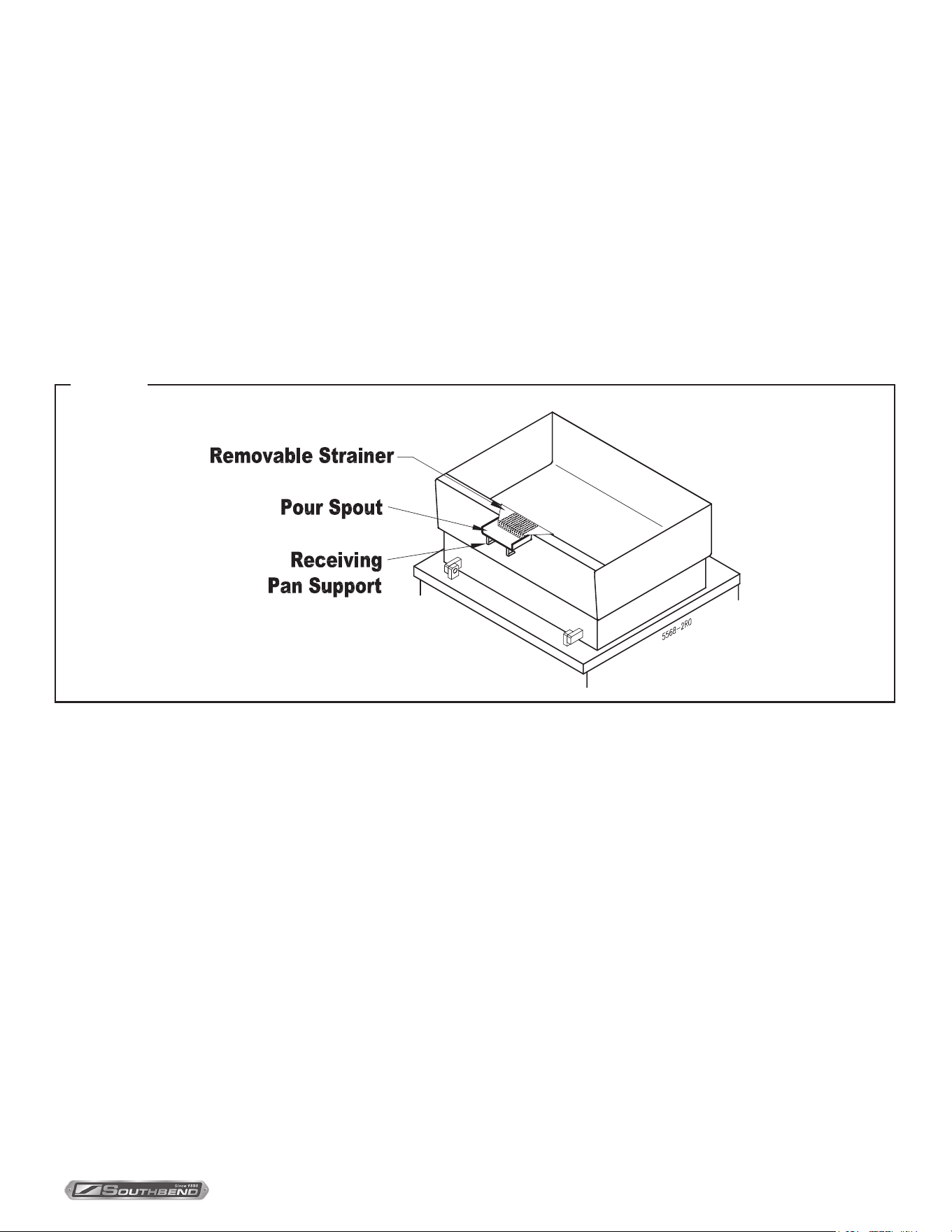
4. Food is poured through the removable strainer (Figure 2) into a food receiving pan positioned under the lip of the
pouring spout (Figure 2).
Figure 2
INSTALLATION & OPERATION MANUAL 10152-SB REV 1 (05/22)
PAGE
12
OF 20
Gas Floor Model Braising Pan With Manual Gearbox TiltPreventive Maintenance
Preventative Maintenance
WARNING
Disconnect the power supply to the appliance before cleaning or servicing.
CAUTION
The appliance and its parts are hot. Use care when operating, cleaning and servicing the appliance.
Cleaning
After each use, allow the tilting braising pan to cool and clean it. Keep exposed cleanable areas of the tilting braising
pan clean at all times. Do not get water in electrical box or any electrical component.
1. Thoroughly wash pan, pouring spout (See Figure 2), lid and exterior surfaces with detergent and warm water.
If necessary, soak pan to remove food that is stuck to pan surface. Rinse thoroughly and wipe dry with a soft
clean cloth.
2. Clean removable strainer and receiving pan support (see Figure 2) with detergent and warm water. Rinse
thoroughly and wipe dry with a soft clean cloth.
3. Clean around burner air mixers and orifices (at rear of burner) if lint has accumulated.
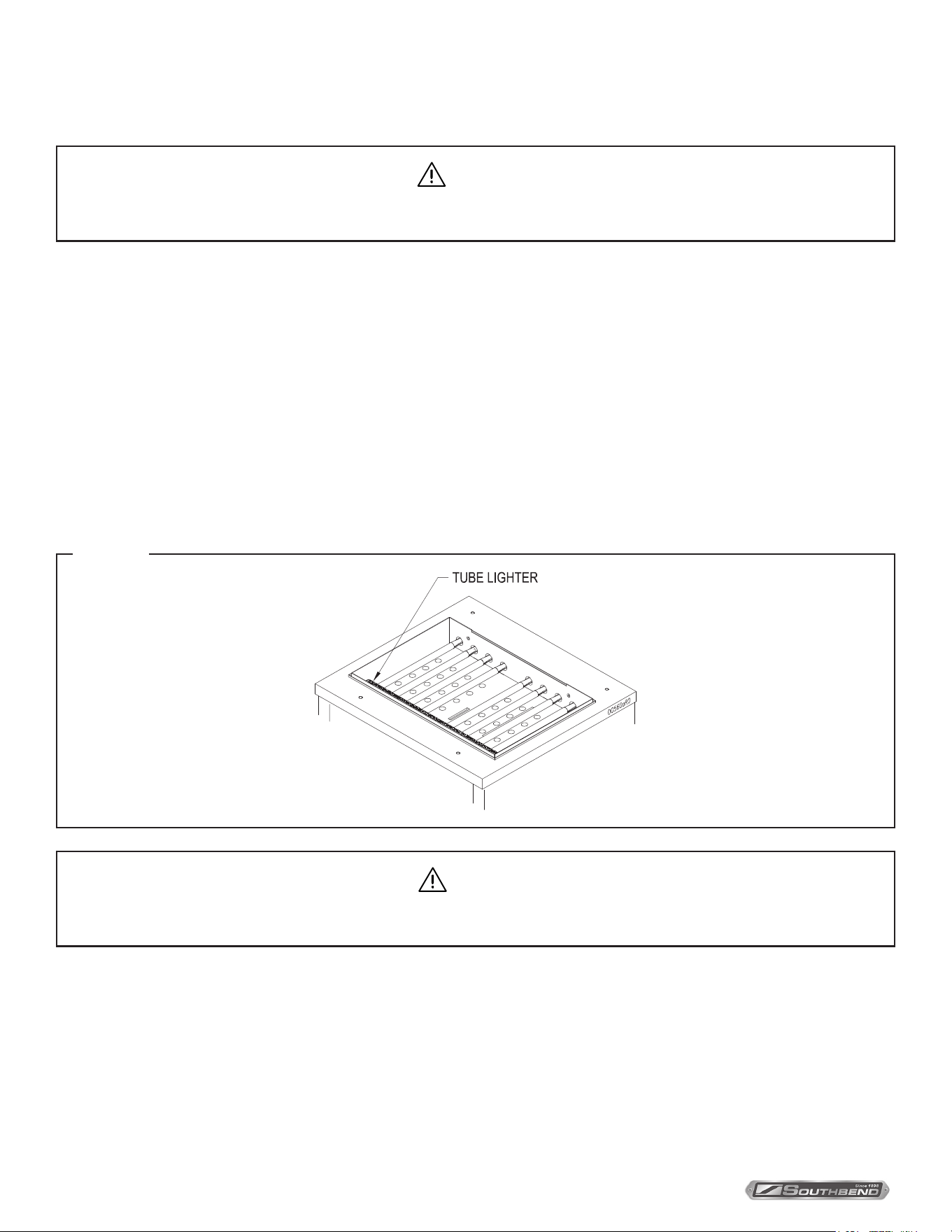
4. Visually ensure tube lighter ports (Figure 3) are unobstructed.
Figure 3
Adjustments
All tilting braising pans are adjusted at the factory.
At least twice a year, have an authorized service person clean and adjust the tilting braising pan for maximum
performance.
INSTALLATION & OPERATION MANUAL 10152-SB REV 1 (05/22)
PAGE
13
OF20
Gas Floor Model Braising Pan With Manual Gearbox Tilt COOKING GUIDELINES
COOKING GUIDELINES
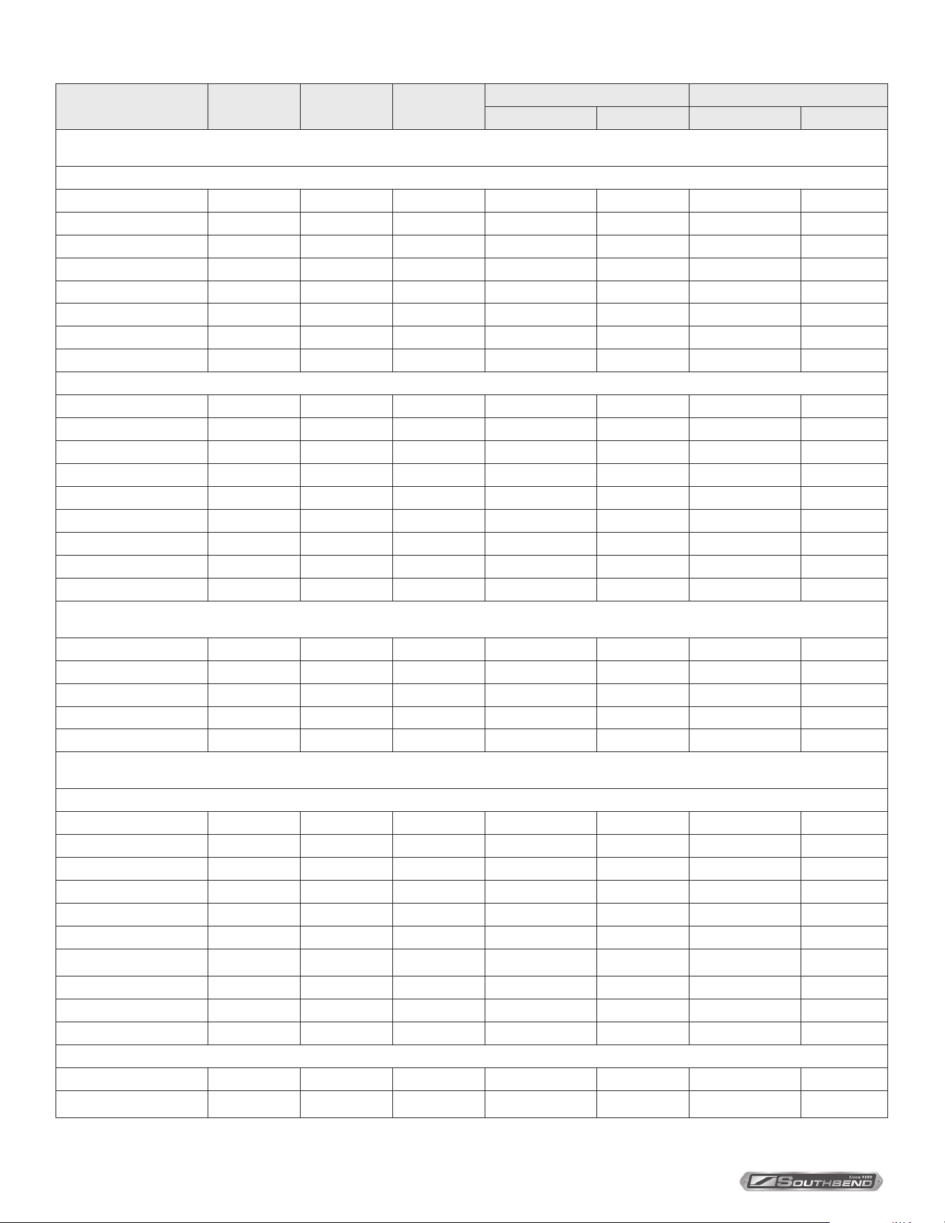
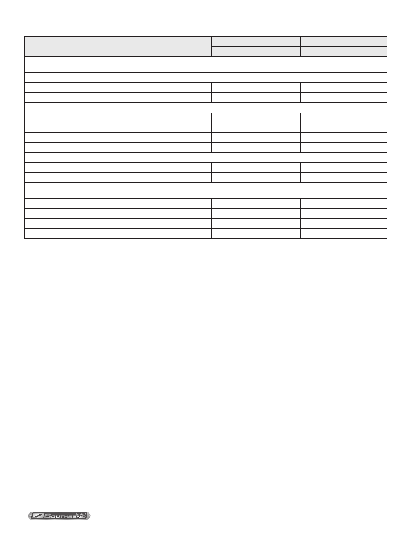
The guidelines given below are suggested quantities, temperature settings, and estimated numbers of orders per load
and per hour. When two temperatures are given, the rst is to start the product, and the second to nish the product.
The following temperatures should be used:
Cooking Method Temperature (°F)
Simmering 200 Maximum
Sautéing 225 - 275
Searing 300 - 350
Frying 325 - 375
Grilling 350 - 450
ITEM
PORTION
SIZE
TEMP. (EF)
BATCHES
PER HOUR
BGLM-30 PER LOAD BGLM-40 PER LOAD
QTY. PORTIONS QTY. PORTIONS
BREAKFAST FOODS
Bacon 3 slices 350 12 2 lb 10 3 lb 15
Eggs
- Boiled - Hard 1 egg 225
5
50 eggs 50 75 eggs 75
- Boiled-Soft 1 egg 225
8
50 eggs 50 75 eggs 75
- Fried 1 egg 400
4
30 eggs 30 45 eggs 45
- Poached 1 egg 225
5
36 eggs 36 60 eggs 60
- Scrambled 1-1/2 eggs 300-200
1
18 gal. 720 28 gal. 1100
French Toast 3 slices 450
7
35 slices 12 50 slices 17
Regular Oatmeal 1/2 cup 250
2
20 lb (100 cups) 500 40 lb (200 cups) 1000
Pancakes 2 each 400 10 30 each 15 50 each 25
FISH
Clams 1 pint 400 10 10 quarts 20 15 quarts 30
Fish Cakes 2 - 3 oz 400
5
70 - 3 oz 35 110 - 3 oz 55
Haddock Fillet 4 oz 400
4
60 - 4 oz 60 90 - 4 oz 90
Halibut Steak 5 oz 450
3
60 - 4 oz 60 90 - 4 oz 90
Lobster 1 - 1 lb 350
4
20 - 1 lb 20 30 - 1 lb 30
Swordsh 5 oz 450
3
50 - 5 oz 50 75 - 5 oz 75
SAUCES, GRAVIES, SOUPS
Brown Gravy 1 oz 350 - 200
2
18 gal. 2300 35 gal. 4500
Cream Sauce 2 oz 250 - 175
1
18 gal. 1150 35 gal. 2250
Cream Soup 6 oz 200
1
18 gal. 375 35 gal. 725
French Onion Soup 6 oz 225
1
18 gal. 350 35 gal. 700
Meat Sauce 4 oz 350 - 200
1
18 gal. 575 35 gal. 1100
VEGETABLES
CANNED 3 oz 400
6
30 lb 125 45 lb 200
FRESH
Beans, Wax, Green 3 oz 400
3
25 lb 125 50 lb 250
Beets 3 oz 400
1
30 lb 125 60 lb 300
INSTALLATION & OPERATION MANUAL 10152-SB REV 1 (05/22)
PAGE
14
OF 20
Gas Floor Model Braising Pan With Manual Gearbox TiltCOOKING GUIDELINES
ITEM
PORTION
SIZE
TEMP. (EF)
BATCHES
PER HOUR
BGLM-30 PER LOAD BGLM-40 PER LOAD
QTY. PORTIONS QTY. PORTIONS
VEGETABLES (continued)
FRESH (continued)
Broccoli 3 oz 400
3
25 lb 125 40 lb 200
Cabbage 3 oz 400
5
20 lb 80 30 lb 125
Carrots 3 oz 400
2
35 lb 150 70 lb 300
Cauliower 3 oz 250
5
15 lb 75 25 lb 125
Corn 1 ear 400
8
50 ears 50 75 ears 75
Potatoes 3 oz 400
2
40 lb 200 60 lb 300
Spinach 4 oz 250 10 40 lb 200 9 lb 35
Turnips 4 oz 400
2
20 lb 100 30 lb 150
FROZEN
Beans, French Green 3 oz 400
6
15 lb 60 22-1/2 lb 90
Lima Beans 3 oz 250
4
15 lb 60 22-1/2 lb 90
Broccoli 3 oz 400
8
12 lb 50 18 lb 75
Sliced Carrots 3 oz 250
6
15 lb 60 22-1/2 lb 90
Small Whole Carrots 3 oz 250
3
15 lb 50 22-1/2 lb 90
Corn 3 oz 250 18 15 lb 50 22-1/2 lb 90
Small Whole Onions 3 oz 250
7
15 lb 50 22-1/2 lb 90
Peas 3 oz 400 10 15 lb 75 22-1/2 lb 110
Spinach 3 oz 400
3
15 lb 75 22-1/2 lb 110
DESSERTS, PUDDINGS, SWEET SAUCES
Butterscotch Sauce 1 oz 200
1
18 gal. 2300 35 gal. 4500
Cherry Cobbler 3 oz 200
1
18 gal. 750 35 gal. 1500
Chocolate Sauce 1 oz 200
1
18 gal. 2300 35 gal. 4500
Cornstarch Pudding 4 oz 200
1
18 gal. 575 35 gal. 1100
Fruit Gelatin 3 oz 250
2
18 gal. 750 35 gal. 1500
MEAT-POULTRY
BEEF
American Chop Suey 6 oz 400 - 225
2
18 gal. 350 35 gal. 700
Beef Stew 8 oz 300
-
18 gal. 280 35 gal. 560
Corned Beef Hash 5 oz 400
5
16 lb 50 25 lb 75
Cheeseburger 3 oz 300 12 7 lb 35 10 lb 50
Hamburger 3 oz 300 15 7 lb 35 10 lb 50
Meatballs 1 oz 400 - 225
3
12-1/2 lb 65 18 lb 100
Pot Roast 2 oz 350 - 200 120 lb 500 180 lb 750
Salisbury Steak 5 oz 400
3
16 lb 50 24 lb 75
Sirloin Steak 6 oz 400
5
15 lb 40 22-1/2 lb 60
Swiss Steak 4 oz 300 - 200
1
25 lb 110 40 lb 160
CHICKEN
Pan Fried 2-1/4’s 350
3
50 pieces 25 80 pieces 40
Whole 2 oz 350 - 200 16 - 5 lb 200 24-5 lb 265
INSTALLATION & OPERATION MANUAL 10152-SB REV 1 (05/22)
PAGE
15
OF20
Gas Floor Model Braising Pan With Manual Gearbox Tilt COOKING GUIDELINES
ITEM
PORTION
SIZE
TEMP. (EF)
BATCHES
PER HOUR
BGLM-30 PER LOAD BGLM-40 PER LOAD
QTY. PORTIONS QTY. PORTIONS
MEAT-POULTRY (continued)
FRANKFURTERS
Grilled 2 oz 300
8
22 lb 176 33 lb 264
Boiled 2 oz 250 12 16 lb 128 25 lb 200
PORK
Bacon 3 slices 350 12 2 lb 10 3 lb 15
Ham Steak 3 oz 400
8
10 lb 50 15 lb 75
Pork Chops 5 oz 350
4
15 lb 50 25 lb 75
Sausage Links 3 links 350
7
30 lb 120 45 lb 180
TURKEY
O Carcass 2 oz 400 - 200
–
3 - 26-30 lb 200 4 - 26-30 lb 275
On Carcass 2 oz 400 - 200
–
4 - 16-20 lb 175 6 - 16-20 lb 265
MISCELLANEOUS
Grilled Cheese Sandwich
1
sandwich
400
8
35 sandwiches
35
50 sandwiches
50
Macaroni & Cheese 8 oz 200
2
18 gal. 300 35 gal. 525
Rice 4 oz 350 - 225
1
20 lb raw 320 40 lb raw 650
Spaghetti 4 oz 350 - 225
2
8 lb raw 200 12 lb raw 300

INSTALLATION & OPERATION MANUAL 10152-SB REV 1 (05/22)
PAGE
16
OF 20
Gas Floor Model Braising Pan With Manual Gearbox TiltTroubleshooting
TROUBLESHOOTING
Burners No Not Come On
1. Gas supply to unit is “OFF”.
2. Manual shut o valve is “OFF”.
3. Thermostat is not turned “ON”.
4. Pan not in lowest position.
5. Ignition control not functioning.
6. Unit electrical supply is not plugged in or turned on.
7. Braising pan has overheated and burners were shut o by high-limit thermostat. Wait for pan to cool.
Burners Produce Carbon Deposits
1. Wrong size orices.
2. Burner air not adjusted properly.
3. Wrong gas supply.
4. Incorrect pressure at supply.

INSTALLATION & OPERATION MANUAL 10152-SB REV 1 (05/22)
PAGE
17
OF20
Gas Floor Model Braising Pan With Manual Gearbox Tilt
Notes
Notes

INSTALLATION & OPERATION MANUAL 10152-SB REV 1 (05/22)
PAGE
18
OF 20
Gas Floor Model Braising Pan With Manual Gearbox Tilt
Notes
Notes

INSTALLATION & OPERATION MANUAL 10152-SB REV 1 (05/22)
PAGE
19
OF20
Gas Floor Model Braising Pan With Manual Gearbox Tilt
Notes
Notes
INSTALLATION & OPERATION MANUAL 10152-SB REV 1 (05/22)
PAGE
20
OF 20
Gas Floor Model Braising Pan With Manual Gearbox Tilt
BGLM-30, BGLM-40, BGLM-40N
and BGLM-60
Gas Floor Model Braising Pan
With Manual Gearbox Tilt
A product with the Southbend Steam name incorporates the best in durability and low maintenance. We all recognize,
however, that replacement parts and occasional professional service may be necessary to extend the useful life of this
appliance. When service is needed, contact a Southbend Steam Authorized Service Agency, or your dealer. To avoid
confusion, always refer to the model number, serial number, and type of your appliance.
SOUTHBEND STEAM
A Middleby Company
1100 Old Honeycutt Road Fuquay-Varina, North Carolina 27526 USA
www.southbendnc.com

