
Company Name : M5Stack Technology Co.,Ltd
Address: Block A10, Expo Bay South Coast, Fuhai Street, Bao'an District, Shenzhen,Guangdong,China
Stamp-S3 Mini
User Manual - FCC
Company Name : M5Stack Technology Co.,Ltd
Address: Block A10, Expo Bay South Coast, Fuhai Street, Bao'an District, Shenzhen,Guangdong,China
1. Description
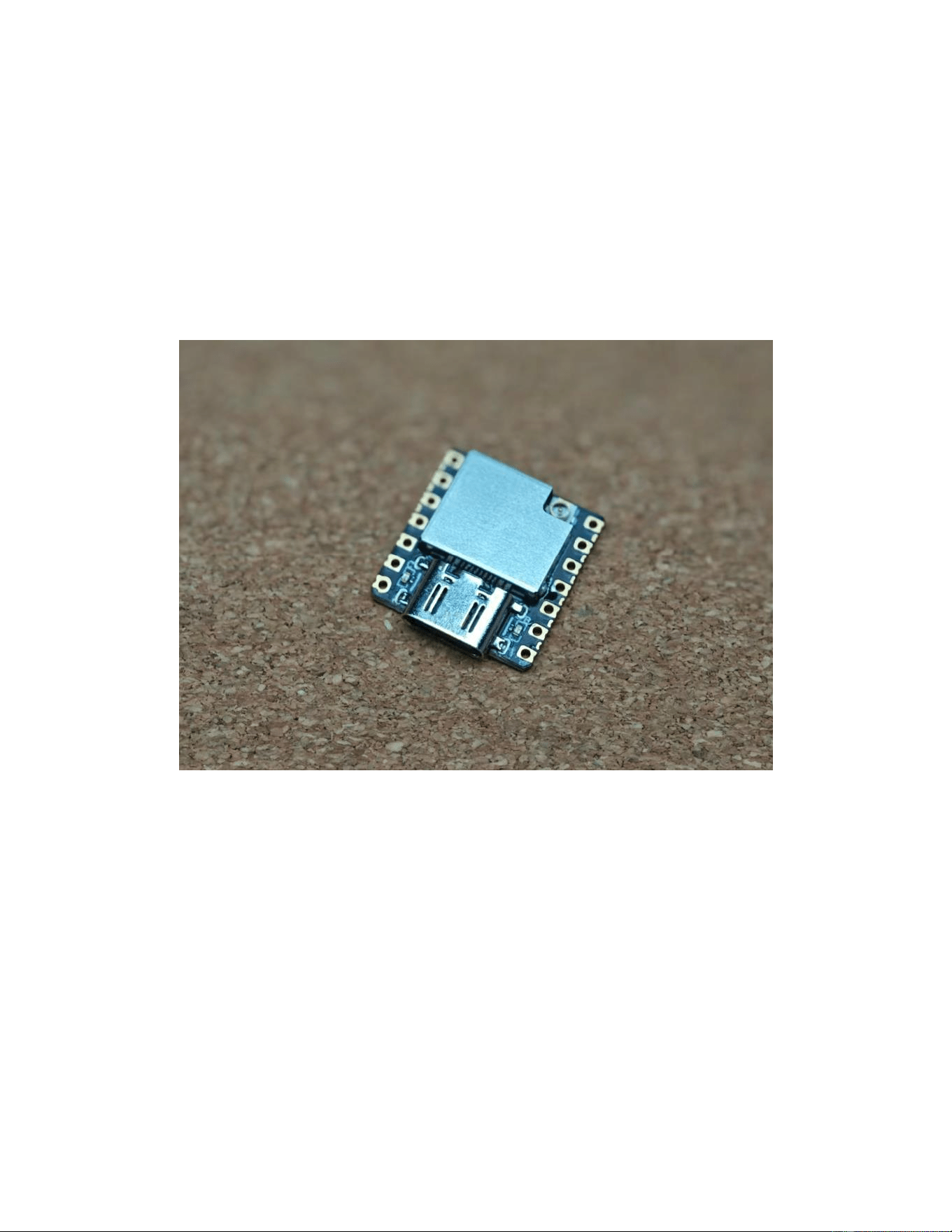
Stamp-S3 Mini is a compact embedded main control module powered by the ESP32-S3-PICO-1-
N8R8 as the core processor, featuring a Xtensa 32-bit LX7 dual-core processor with 2.4 GHz Wi-Fi
support. It is equipped with 8 MB Flash and 8 MB PSRAM onboard. The module offers flexible
power supply options, integrating a USB Type-C interface, supporting DC 5 V input. The clock
source is the internal 40 MHz crystal oscillator integrated in the ESP32-S3-PICO-1 module, so no
external crystal is required. Its hybrid dual-row pin layout provides multiple GPIO resources within a
compact footprint, with outer 2.54 mm-pitch through-hole pads compatible with standard pin headers
and inner 1.27 mm-pitch castellated half-hole pads supporting reflow soldering. It is suitable for IoT
end-product development in smart homes, industrial sensing, and other embedded applications.
Company Name : M5Stack Technology Co.,Ltd
Address: Block A10, Expo Bay South Coast, Fuhai Street, Bao'an District, Shenzhen,Guangdong,China
2. Specifications
Specification
Parameters
SoC
ESP32-S3-PICO-1-N8R8 @ dual-core Xtensa LX7 processor,
up to 240 MHz
Crystal Oscillator
Internal 40 MHz crystal oscillator (integrated in the ESP32-S3-
PICO-1 module)
PSRAM
8 MB
Flash
8 MB
Wireless
2.4 GHz Wi-Fi + Bluetooth Low Energy
Input Power
USB Type-C: DC 5 V input
GPIO Pins
G0-G18
Operating Temperature
-10 ~ 60 ℃
Frequency Range
BLE: 2402-2480 MHz;
2.4 GHz Wi-Fi: 2412-2462 MHz (channels 1-11)
Company Name : M5Stack Technology Co.,Ltd
Address: Block A10, Expo Bay South Coast, Fuhai Street, Bao'an District, Shenzhen,Guangdong,China
3. Quick Start
3.1 Preparation
1. Install the Arduino IDE from the official Arduino website:
https://www.arduino.cc/en/Main/Software
2. Add the following Board Manager URL to File -> Preferences -> Additional Boards Manager URLs:
https://espressif.github.io/arduino-esp32/package_esp32_dev_index.json
3. Open the Boards Manager, search for ESP32, and install the ESP32 board package.
4. Select ESP32S3 Dev Module and configure USB CDC On Boot as Enabled, PSRAM as OPI
PSRAM, and USB Mode as Hardware CDC and JTAG.
3.2 Wi-Fi Scan
Select Examples -> WiFi -> WiFiScan, choose the port corresponding to the device, and click the
compile and upload button. After uploading is complete, open the Serial Monitor to view Wi-Fi scan
information.
Company Name : M5Stack Technology Co.,Ltd
Address: Block A10, Expo Bay South Coast, Fuhai Street, Bao'an District, Shenzhen,Guangdong,China
3.3 BLE Scan
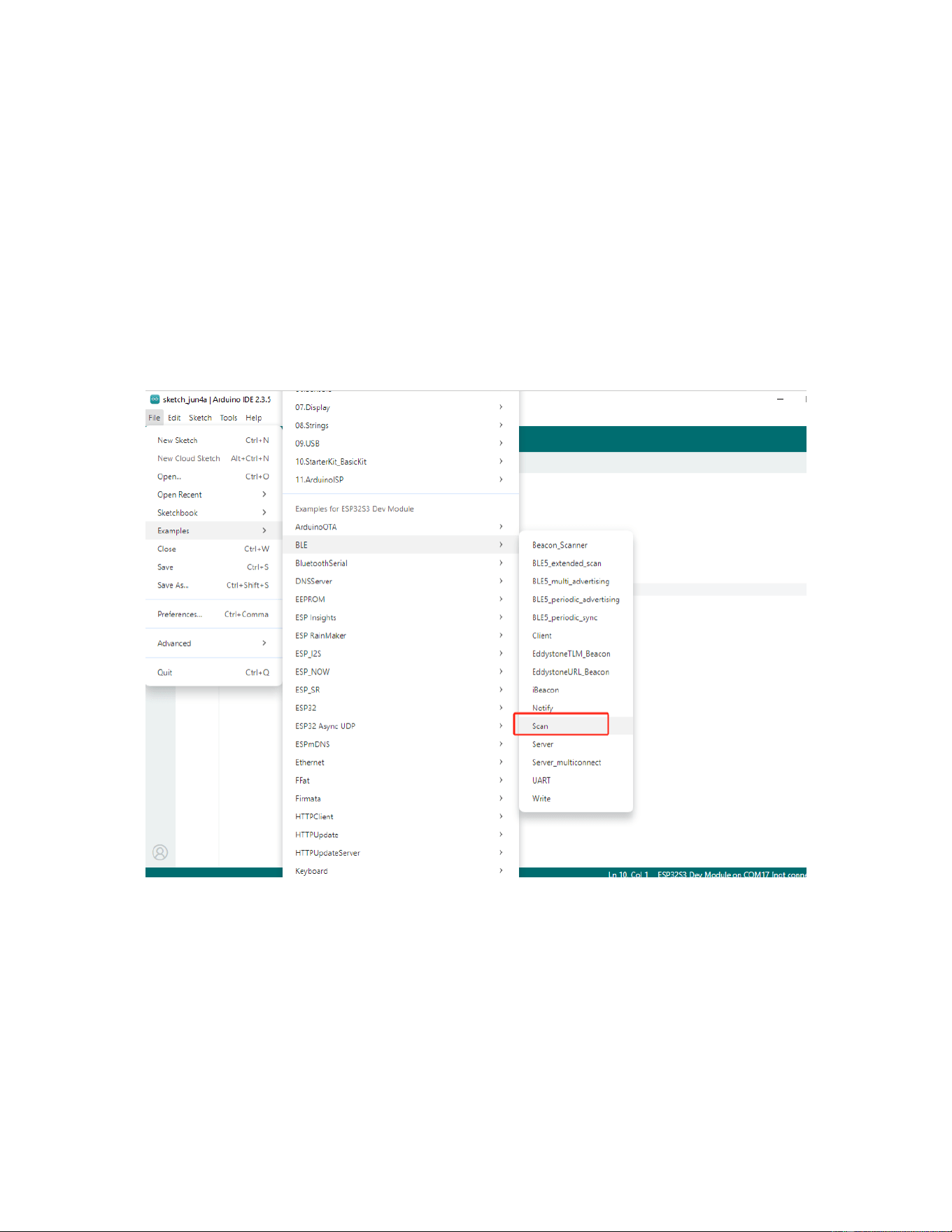
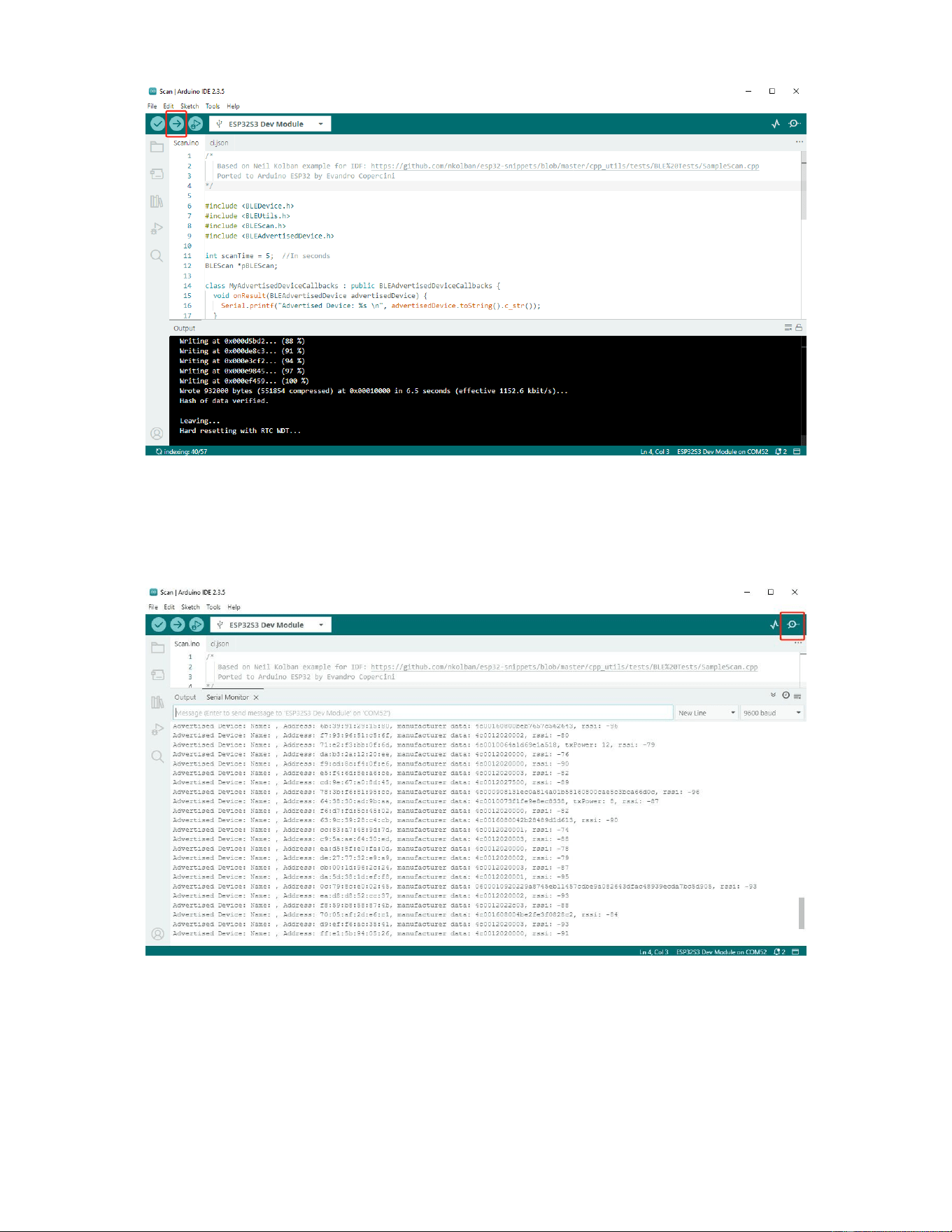
Select Examples -> BLE -> Scan, choose the port corresponding to the device, and click the compile
and upload button. After uploading is complete, open the Serial Monitor to view BLE scan
information.

Company Name : M5Stack Technology Co.,Ltd
Address: Block A10, Expo Bay South Coast, Fuhai Street, Bao'an District, Shenzhen,Guangdong,China
4. FCC Warning
FCC Caution:
Any changes or modifications not expressly approved by the party responsible for compliance could
void the user's authority to operate the equipment.
This device complies with part 15 of the FCC Rules. Operation is subject to the following two
conditions: (1) This device may not cause harmful interference, and (2) this device must accept any
interference received, including interference that may cause undesired operation.
IMPORTANT NOTE:
Note: This equipment has been tested and found to comply with the limits for a Class B digital device,
pursuant to part 15 of the FCC Rules. These limits are designed to provide reasonable protection
against harmful interference in a residential installation. This equipment generates, uses and can
radiate radio frequency energy and, if not installed and used in accordance with the instructions,
may cause harmful interference to radio communications. However, there is no guarantee that
interference will not occur in a particular installation. If this equipment does cause harmful
interference to radio or television reception, which can be determined by turning the equipment off
and on, the user is encouraged to try to correct the interference by one or more of the following
measures:
—Reorient or relocate the receiving antenna.
—Increase the separation between the equipment and receiver.
—Connect the equipment into an outlet on a circuit different from that to which the receiver is
connected.
—Consult the dealer or an experienced radio/TV technician for help.
FCC Radiation Exposure Statement:
This equipment complies with FCC radiation exposure limits set forth for an uncontrolled
environment. This equipment should be installed and operated with minimum distance 20cm
between the radiator& your body.

Company Name : M5Stack Technology Co.,Ltd
Address: Block A10, Expo Bay South Coast, Fuhai Street, Bao'an District, Shenzhen,Guangdong,China
Integration instructions for host product manufacturers
2.1 General
This document refers to FCC 996369 D03 OEM Manual v01r01, and lists the
requirements for module integrators.
2.2 List of applicable FCC rules
CFR 47 FCC PART 15 SUBPART C has been investigated. It is applicable to the
modular.
2.3 Specific operational use conditions
This module is stand-alone modular. If the end product will involve the Multiple
simultaneously transmitting condition or different operational conditions for a stand-
alone modular transmitter in a host, host manufacturer have to consult with module
manufacturer for the installation method in end system.
2.4 Limited module procedures
Not applicable.
2.5 Trace antenna designs
Not applicable.
2.6 RF exposure considerations
To maintain compliance with FCC’s RF Exposure guidelines, this equipment should be
installed and operated with minimum distance of 20cm from your body.
2.7 Antennas
This radio transmitter FCC ID: 2AN3WM5STAMPS3MINI has been approved by
Federal Communications Commission to operate with the antenna types listed below,
with the maximum permissible gain indicated. Antenna types not included in this list that
have a gain greater than the maximum gain indicated for any type listed are strictly
prohibited for use with this device.
Company Name : M5Stack Technology Co.,Ltd
Address: Block A10, Expo Bay South Coast, Fuhai Street, Bao'an District, Shenzhen,Guangdong,China
For model
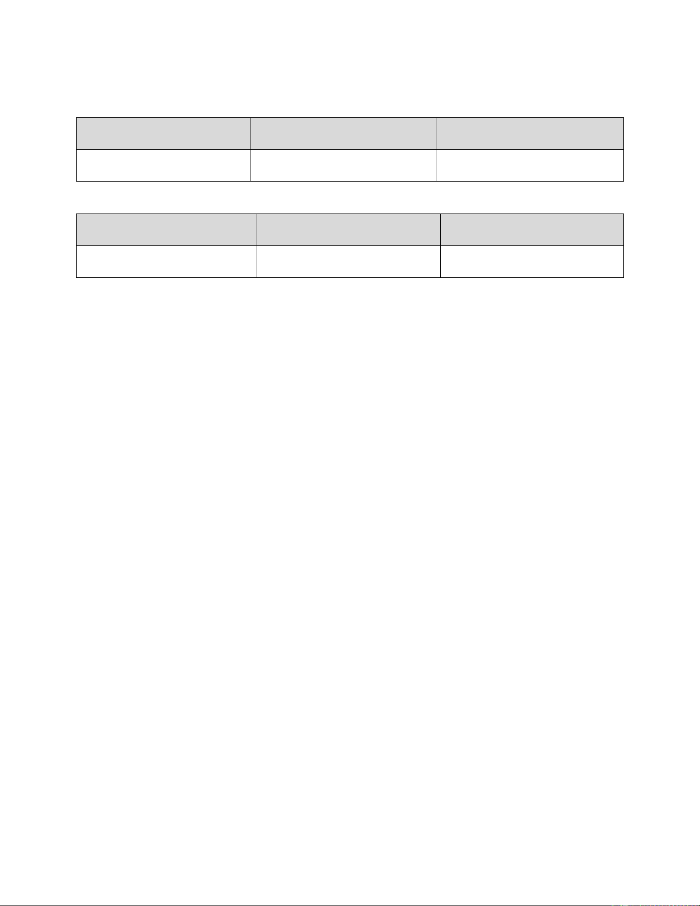
Stamp-S3 Mini, the EUT using one antenna:
BLE
Frequency(MHz)
Antenna Gain(dBi)
Type
2402-2480
2.11
PCB
2.4G Wi-Fi
Frequency(MHz)
Antenna Gain(dBi)
Type
2412-2462
2.11
PCB
For specific information, please refer to the Antenna spec report.
2.8 Label and compliance information
The final end product must be labeled in a visible area with the following "Contains
FCC ID: 2AN3WM5STAMPS3MINI”
2.9 Information on test modes and additional testing requirements
Host manufacturer is strongly recommended to confirm compliance with FCC
requirements for the transmitter when the module is installed in the host.
2.10 Additional testing, Part 15 Subpart B disclaimer
Host manufacturer is responsible for compliance of the host system with module
installed with all other applicable requirements for the system such as Part 15 B.