
Company Name:M5Stack Technology Co.,Ltd
Address: Block A10, Expo Bay South Coast, Fuhai Street, Bao'an District, Shenzhen,Guangdong,China
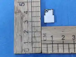
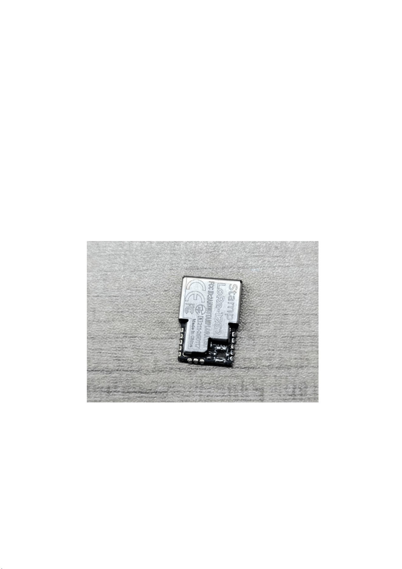
Stamp LoRa-1262
Company Name:M5Stack Technology Co.,Ltd
Address: Block A10, Expo Bay South Coast, Fuhai Street, Bao'an District, Shenzhen,Guangdong,China
1.
Description
Stamp LoRa-1262 is an ultra-compact embedded LoRa communication module
featuring a high-performance SX1262 LoRa transceiver, operating over the 868–923 MHz
frequency band.
Despite its miniature size, the module delivers powerful performance and maintains
stable and reliable RF characteristics, even under complex and rapidly changing
environmental conditions.
Allow users to select a combination of PCB-outlet antenna connectors to meet
specific application requirements.
This flexibility makes Stamp LoRa-1262 easy to integrate into hardware designs of
various sizes and form factors, and well suited for IoT, remote monitoring, and low-power
wireless applications.
Company Name:M5Stack Technology Co.,Ltd
Address: Block A10, Expo Bay South Coast, Fuhai Street, Bao'an District, Shenzhen,Guangdong,China
2.
Specifications
Specification
Parameters
LoRa Module
SX1262
LoRa Frequency Range For CE
868.100MHz-868.500MHz
Transmit Maximum ERP For CE
LoRa: 10.52dBm
LoRa Programmable Bit Rate
Up to 300kbps
LoRa Communication Interface
SPI
LoRa Receiver Sensitivity
–147 dBm (LoRa low data rate mode)
Supported Modulation Modes
CSS
Antenna Type:
Dipole Antenna
Receiver category
The equipment provider declared that the
receiver category for the EUT is 2
Hardware version NO.
V1.0
Software version NO.
V1.0
3.
Quick Start
3.1
LoRa TX
Allow users to control the device via SPI by drawing wires or flying leads on the board.

Company Name:M5Stack Technology Co.,Ltd
Address: Block A10, Expo Bay South Coast, Fuhai Street, Bao'an District, Shenzhen,Guangdong,China
4.
FCC Warning
FCC Caution:
Any Changes or modifications not expressly approved by the party responsible for
compliance could void the user's authority to operate the equipment.
This device complies with part 15 of the FCC Rules. Operation is subject to the following two
conditions: (1) This device may not cause harmful interference, and (2) this device must accept
any interference received, including interference that may cause undesired operation.
IMPORTANT NOTE:
Note: This equipment has been tested and found to comply with the limits for a Class B digital
device, pursuant to part 15 of the FCC Rules. These limits are designed to provide reasonable
protection against harmful interference in a residential installation. This equipment generates,
uses and can radiate radio frequency energy and, if not installed and used in accordance with
the instructions, may cause harmful interference to radio communications. However, there
is no guarantee that interference will not occur in a particular installation. If this equipment
does cause harmful interference to radio or television reception, which can be determined
by turning the equipment off and on, the user is encouraged to try to correct the
interference by one or more of the following measures:
Reorient or relocate the receiving antenna.
— Increase the separation between the equipment and receiver.
— Connect the equipment into an outlet on a circuit different from that to which the
receiver is connected.
Consult the dealer or an experienced radio/TV technician for help.
FCC Radiation Exposure Statement:
This equipment complies with FCC radiation exposure limits set forth for an uncontrolled
environment. This equipment should be installed and operated with minimum distance
20cm between the radiator& your body.

Company Name:M5Stack Technology Co.,Ltd
Address: Block A10, Expo Bay South Coast, Fuhai Street, Bao'an District, Shenzhen,Guangdong,China
Integration instructions for host product manufacturers
2.1 General
This document refers to FCC 996369 D03 OEM Manual v01r01, and lists the requirements for
module integrators.
2.2 List of applicable FCC rules
CFR 47 FCC PART 15 SUBPART C has been investigated. It is applicable to the modular.
2.3 Specific operational use conditions
This module is stand-alone modular. If the end product will involve the Multiple
simultaneously transmitting condition or different operational conditions for a stand-alone
modular transmitter in a host, host manufacturer have to consult with module manufacturer
for the installation method in end system.
2.4 Limited module procedures
Not applicable.
2.5 Trace antenna designs
Not applicable.
2.6 RF exposure considerations
To maintain compliance with FCC’s RF Exposure guidelines, this equipment should be
installed and operated with minimum distance of 20cm from your body.
2.7 Antennas
The Lora antenna is dipole antenna, the antenna gain is 3.08dBi.
2.8 Label and compliance information
The final end product must be labeled in a visible area with the following "Contains
FCC ID: 2AN3WSTAMPLORA1262”
2.9 Information on test modes and additional testing requirements
Host manufacturer is strongly recommended to confirm compliance with FCC requirements
for the transmitter when the module is installed in the host.
2.10 Additional testing, Part 15 Subpart B disclaimer
Host manufacturer is responsible for compliance of the host system with module installed
with all other applicable requirements for the system such as Part 15 B.

Company Name:M5Stack Technology Co.,Ltd
Address: Block A10, Expo Bay South Coast, Fuhai Street, Bao'an District, Shenzhen,Guangdong,China
FOR CE
Conformity Assessment of the Radio Module to the RED
This radio module is for professional installation only. When installing this radio module
permanently into a host product to a create new radio equipment device; the manufacturer
responsible for placing the final radio product on the market in the EU must assess if the
combination of this radio module and the host product complies with the essential
requirements of the RE Directive 2014/53/EU.
Firmware version: v2.3
Test Antenna: dipole antenna and maximum gain 3.54dBi
The final radio product will need to be fully assessed to Article 3.1a of the RED, for product
safety With regard to RF exposure for Article 3.1a of the RED, the manufacturer of the final
radio product will need to assess if the compliance assessment of the original radio
equipment/module remains relevant to the final radio product, or if further action is
necessary. The radio transmitter cannot transmit more than 20 mW output power, then the
final radio product assessment could conclude that the final radio product is compliant with
RF exposure requirements without additional actions.
If the final radio equipment is used at a closer distance from a person or domesticated
animal than the radio module was assessed, then the final radio product assessment could
not automatically conclude that the final radio product is compliant with the RF exposure
requirements without additional actions; and further assessment is necessary. The final radio
product will need to be fully assessed to Article 3.1b of the RED, for EMC. EMC testing of the
radio module will have been performed on some sort of temporary host or test jig; but now
the module is in a new host product and the EMC performance of the final radio product
must be assessed. Most likely the host product will have its own EMC assessment for other
functions, which should be performed with the radio module installed; and inclusion of the
radio module into the host product will also require an assessment, such as to the relevant
applicable part of EN 301 489, on the final radio product.
In theory, radio transmitter or receiver measurements made as conducted measurements at
a radio module antenna port may be considered applicable to the radio performance of the
final radio product. However, in this example, the radio module does not have an antenna
port. The radio module has a pin which leads through a PCB trace to an antenna on the host
product. If the manufacturer of the final radio product wishes to use conducted power,
conducted emissions or receiver performance measurements from the radio module to show
compliance of the final radio product, then they will need to exactly follow the detailed
instructions from the radio module manufacturer; including input voltage, driver software,
environmental conditions, antenna trace layout design construction and material, circuit
board layout design construction and material, nearby circuitry, etc. In reality, it is expected
that manufacturers of final radio products will need to test the output power, conducted
spurious emissions and receiver performance requirements on the final radio product; and
not take the results of those test cases from the radio module test reports. Radiated test
cases will also need to be performed on the final radio product.
The receiver category is 2.