
Midea Kitchen Appliance
MIDEA SERVICE MANUAL
This document is published to be used for after sales service only. The content are subject
to change without prior notice.
In interest of user safety the appliance should be restored to its original condition and only
parts identical to those should be applied.
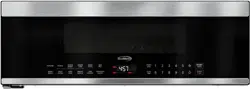
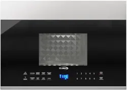
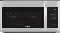
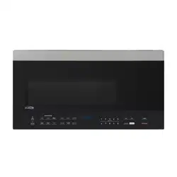
MICROWAVE OVEN
Type: OVER THE RANGE
2017
December,

CONTENTS
CAUTIONS .......................................................................................
SERVICE INFORMATION ..............................................................
Microwave Leakage Test .....................................................................
3. Outer Case Removal ..............................................................................
2. Removal of Oven From Wall .............................................................................
1. Hood Ehaust Louver Removal .............................................................................
5. High Voltage
6. Magnetron Removal
8. Hood Fan Motor Removal ..............................................................................
1.
2.
Description And Function Of Component .....................................................
COMPONENT TEARDOWN .....................................................................
Diode And High Voltage
TROUBLESHOOTING AND TESTING .........................................................
Troubleshooting Guide Chart ..............................................................................
Test Procedures ..............................................................................
ATTACHED FILES LIST ......................................................................
Grounding Instructions .....................................................................
4. High Voltage Transformer Removal ....................................................................
Capacitor Removal ..................................
emoval .............................................................................
9. Thermal Cut-Out(Cavity) Removal ....................................................................
7. Hood Fan Thermal Cut-Out Removal ....................................................................
10. Cooling Fan Motor Removal
11. Turntable Motor And Hood Lamp Sockets Removal .........................................
12. Oven Lamp And Lamp Sockets Removal .........................................................
13. Control Assembly R
14. Stirrer Motor Removal ............................................................................
15. Stirrer Bracket And Stirrer Fan Removal ...........................................................
16. Door Assembly Removal .............................................................................
17. Sensor Humidity Removal .............................................................................
18. Convection Motor Removal .............................................................................
19. Thermal Cut-Out(Convection) Removal ............................................................
..............................................................................
...............................................................................
1
19
2
2
2
3
4
4
4
4
5
5
5
5
6
6
6
6
6
7
7
7
7
7
8
8
9
9
10
CAUTIONS
THE OVEN IS TO BE SERVICED ONLY
BY PROPERLY QUALIFIED SERVICE
PERSONNEL.
1
WARNING TO SERVICE PERSONNEL
Microwave ovens contain circuitry capable of pro-
ducing very high voltage and current, contact with
following parts
may result in a severe, possibly
fatal, electrical shock.
(Example)
High Voltage Capacitor, High Voltage Power
Transformer, Magnetron, High Voltage Rectifier
Assembly, High Voltage Harness etc..
Read the Service Manual carefully and follow all
instructions.
Before Servicing
1. Disconnect the power supply cord , and then
remove outer case.
2. Open the door and block it open.
3. Discharge high voltage capacitor.
WARNING: RISK OF ELECTRIC SHOCK.
DISCHARGE THE HIGH-VOLTAGE
CAPACITOR BEFORE SERVICING.
The high-voltage capacitor remains charged about 60
seconds after the oven has been switched off. Wait for
60 seconds and then short-circuit the connection of the
high-voltage capacitor (that is the connecting lead of the
high-voltage ) against the chassis with the use of
an insulated screwdriver.
Whenever troubleshooting is performed the power supply
must be disconnected. It may, in some cases, be necessary
to connect the power supply after the outer case has been
removed, in this event,
1. Disconnect the power supply cord, and then remove
outer case.
2. Open the door and block it open.
3. Discharge high voltage capacitor.
4. Disconnect the leads to the primary of the power
transformer.
5. Ensure that these leads remain isolated from other
components and oven chassis by using insulation
tape.
6. After that procedure, reconnect the power supply cord.
When the testing is completed,
1. Disconnect the power supply cord, and then remove
outer case.
2. Open the door and block it open.
3. Discharge high voltage capacitor.
4. Reconnect the leads to the primary of the power
transformer.
5. Reinstall the outer case (cabinet).
6. Reconnect the power supply cord after the outer case
is installed.
7. Run the oven and check all functions.
After repairing
1. Reconnect all leads removed from components during
testing.
2. Reinstall the outer case (cabinet).
3. Reconnect the power supply cord after the outer case
is installed.
4. Run the oven and check all functions.
Microwave ovens should not be run empty. To test for the
presence of microwave energy within a cavity, place a cup
of cold water on the oven turntable, close the door and set
the power to HIGH and set the microwave timer for two (2)
minutes. When the two minutes has elapsed (timer at zero)
carefully check that the water is now hot. If the water remains
cold carry out Before Servicing procedure and re-examine
the connections to the component being tested.
When all service work is completed and the oven is fully
assembled, the microwave power output should be checked
and microwave leakage test should be carried out.
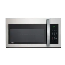
Don't Touch !
Danger High Voltage
diode
CAUTIONS
• Be sure to check microwave leakage prior to
servicing the oven if the oven is operative prior to
servicing.
• The service personnel should inform the
manufacture importer, or assembler of any
certified oven unit found to have a microwave
emission level in excess of 5 mW/cm
2
and should
repair any unit found to have excessive emission levels
at no cost to the owner and should ascertain the cause
of the excessive leakage. The service personnel
should instruct the owner not to use the unit until the
oven has been brought into compliance.
• If the oven operates with the door open, the service
personnel should:
- Tell the user not to operate the oven.
- Contact the manufacturer.
• The service personnel should check all surface and
vent openings for microwave leakage.
• Check for microwave leakage after every servicing.
The power density of the microwave radiation leakage
emitted by the microwave oven should not exceed
4 mW/cm
2
. Always start measuring of an unknown field
to assure safety for operating personnel from radiation
leakage.
MEASURING MICROWAVE ENERGY
LEAKAGE
• Pour 275±15cc of 20±5°C(68±9°F) water in a beaker
which is graduated to 600 cc, and place the beaker
on the center of the turntable.
• Set the energy leakage monitor to 2450 MHz and
use it following the manufacturer's recommended
test procedure to assure correct result.
• When measuring the leakage, always use the 2-
inch (5cm) spacer supplied with the probe.
• Operate the oven at its maximum output.
• Measure the microwave radiation using and
electromagnetic radiation monitor by holding the
probe perpendicular to the surface being measured
Move probe along shaded area
Probe scanning speed
Less than 2.5 cm/sec
( 1in/sec)
Microwave Leakage Test
Grounding Instructions
2
SERVICE INFORMATION
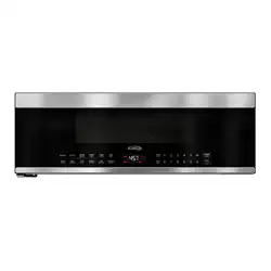
This oven is equipped with a three prong grounding
plug. It must be plugged into a wall receptacle that is
properly installed and grounded in accordance with the
National Electrical Code, local codes and ordinances.
In the event of an electrical short circuit, grounding
reduces the risk of electric shock by providing an
3-Pronged Plug
Grounded
Receptacle Box
Grounding Pin
3-Pronged Receptacle
escape wire for the electric current.
vapors given off from the heating foods. It is then exhausted
through the exhausting air vents at the oven cavity.
HOOD
FAN MOTOR
The hood fan motor is a two-speeds, single-phase, double
pole induction type, requiring a hood fan capacitor. It is
located outside the upper rear part of the oven cavity, is
to remove, from around the oven, hot air rising from the
conventional electric or gas range over which it is installed.
This air is then expelled either vertically or horizontally
through the customer supplied duct system, or discharged
back into the kitchen.
HOOD LAMP
The hood lamps are mounted at the hood lamp angle on
the base cover. The hood lamps can be turned off and on
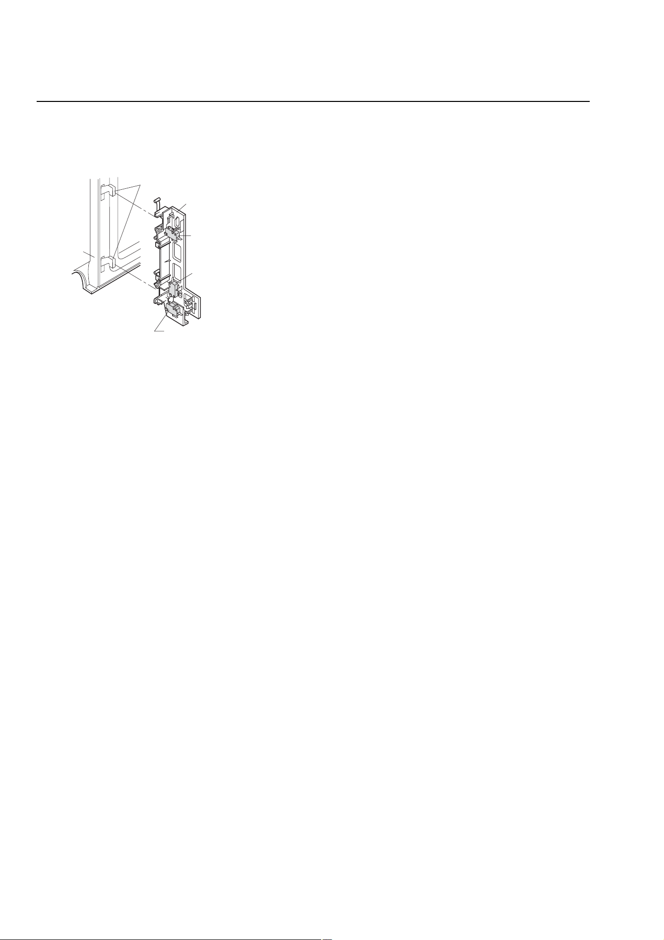
Latch hook
Primary interlock switch
Latch heads
Monitor switch
Door sensing switch
Door
DOOR OPEN MECHANISM
The door is opened by pulling the door handle, refer to the
Figure D-1.
CAUTION: BEFORE REPLACING A BLOWN MONITOR
FUSE TEST THE DOOR SENSING SWITCH,
SECONDARY INTERLOCK RELAY (RY2), RE-
LAY (RY1), PRIMARY INTERLOCK SWITCH
AND MONITOR SWITCH FOR PROPER
OPERATION. (REFER TO CHAPTER "TEST
PROCEDURE").
NOTE: MONITOR FUSE AND MONITOR SWITCH ARE
REPLACED AS AN ASSEMBLY.
THERMAL CUT-OUT (HOOD )
This thermal cut-out located on the right base plate. It
is designed to automatically turn on the hood fan motor
whenever the hot air rising from the conventional range
below causes the temperature at the thermal cut-out to rise
to158
O
F (70
O
C) or higher, thus removing this hot air from
around microwave oven. When the temperature around the
thermal cut-out drops to 104
O
F (40
O
C) or lower, the thermal
cut-out shuts off the hood fan motor.
THERMAL CUT-OUT (CAVITY )
This thermal cut-out is located on the top of the oven cavity.
It is designed to prevent damage to the oven unit if the food
in the oven catches fire due to overheating produced by
improper setting of cooking time or failure of control unit.
Under normal operation, the thermal cut-out remains closed.
However, the thermal cut-out will open at 230
O
F (110
O
C)
causing the oven to shut down.
TURNTABLE MOTOR
The turntable motor rotates the turntable located on the
bottom of the oven cavity, so that the foods on the turnta-
ble cook evenly during cooking. Turntable will turn in either
COOLING FAN MOTOR
The cooling fan motor drives a blade which draws external
cool air. This cool air is directed through the air vanes sur-
rounding the magnetron and cools the magnetron. This air is
channelled through the oven cavity to remove steam and
Figure D-1. Door Open Mechanism
DOOR SENSING SWITCH, PRIMARY INTERLOCK
SWITCH
The primary interlock switch is mounted in the upper position
of the latch hook, the door sensing switch in the primary
interlock system is mounted in the lower position of the
latch hook is mounted on upper position of the latch hook.
They are activated by the latch heads on the door. When
the door is opened, the switches interrupt the circuit to all
components. A cook cycle cannot take place until the door
is firmly closed thereby activating both interlock switches.
The primary interlock system consists of the door sensing
switch and secondary interlock relay located on the control
circuit board.
MONITOR SWITCH
The monitor switch is activated (the contacts opened) by the
latch head on the door while the door is closed. The switch
is intended to render the oven inoperative, by means of
blowing the monitor fuse, when the contacts of the second-
ary interlock relay (RY2) and primary interlock switch fail to
open when the door is opened.
Functions:
1. When the door is opened, the monitor switch contact
close (to the ON condition) due to their being normally
closed. At this time the secondary interlock relay (RY2),
primary interlock switch are in the OFF condition (contacts
open) due to their being normally open contact switches.
And the contacts of relay (RY1) are in the ON condition
(contacts close).
2. As the door goes to a closed position, the monitor switch
contacts are first opened and then the door sensing
switch and the primary interlock switch contacts close.
(On opening the door, each of these switches operate
inversely.)
3. If the door is opened, and the secondary interlock relay
(RY2) and primary interlock switch contacts fail to open,
the monitor fuse blows simultaneously with closing of the
direction.
.
Description And Function Of Component
3
COMPONENT TEARDOWN
1. Disconnect oven from power supply before
removing outer case.
2. Discharge the high voltage capacitor before
touching any oven components or wiring.
CAUTION
To discharge the high voltage capacitor, wait for 60
seconds and then short-circuit the connection of the
high-voltage capacitor (that is the connecting lead of
the high-voltage diode) against the chassis with the
use of an insulated screwdriver.
NOTE
Remove the oven from the wall and proceed as follows:
1. Disconnect the power supply cord.
2. Open the door and block it open.
3. To discharge the high voltage capacitor, wait for 60sec.
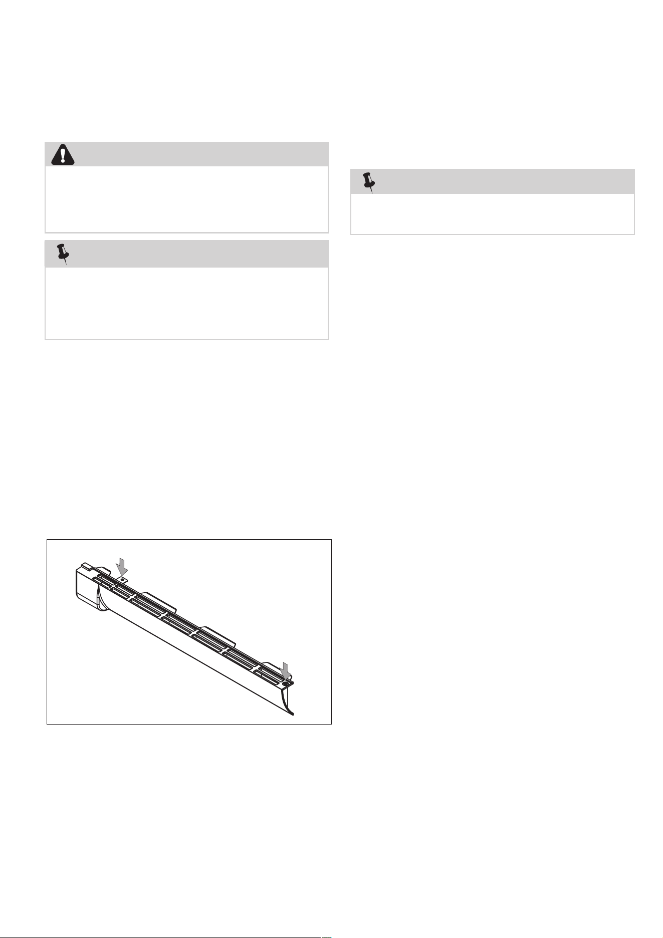
4. Remove the screws on the top holding the hood
exhaust louver to the oven cavity front face plate.
5. Pull the hood exhaust louver from the oven cavity by
pushing the left tab of the hood exhaust
louver to remove.
6. Now, the hood exhaust louver is free.
Tab (left )
Push
Hood Exhaust
Louver
Push
1. Disconnect the power supply cord, and uncoil the
power supply cord.
2. To discharge the high voltage capacitor, wait for 60sec.
3. Remove the turntable tray and support from the oven
cavity.
4. Remove the three (3) screws holding the oven
(outer case cabinet) to the top cabinet.
5. While supporting the front of the oven,
and release
the oven from the unit mounting plate.
6. Pull the power cord out of the wall cabinet and
remove the oven.
7. The oven is now free and can be placed on the work
surface selected for servicing the oven.
8. Installation is the reverse of this procedure.
Two persons are recommended to remove the oven
from a wall installation.
NOTE
Remove the oven from the wall and proceed as follows:
1. Disconnect the power supply cord.
2. Open the door and block it open.
3. To discharge the high voltage capacitor, wait for 60sec.
4. Remove screws holding the top stay to the hood fan
motor or the oven, and remove it.
5. Remove the seven (7) screws from the rear of the
outer case cabinet and two (2) screws at right,and
five (5) screws at top,and four (4) screws at bottom.
6. Slide the outer case cabinet back to free it from
retaining clips on the cavity face plate.
7. Now, the outer case is free.
1. Hood Exhaust Louver Removal
2. Removal Of Oven From Wall
3. Outer Case Removal
4

1. Disconnect the power supply cord, remove oven
from wall, then remove outer case.
2. Open the door and block it open.
3. Discharge high voltage capacitor.
4. Remove the screws holding the base plate to
the oven cavity and outer case on the bottom,
disconnect the wires from turntable motor and two
cooktop lamps. And remove the base plate.
5. Disconnect main wire harness from transformer.
6. Disconnect high voltage wire from the transformer.
7. Disconnect filament leads of transformer from the
magnetron and capacitor.
8. Remove the screws holding the transformer to
bottom plate.
4. High Voltage Transformer Removal
Capacitor Removal
1. Disconnect the power supply cord, remove oven
from wall, then remove outer case.
2. Open the door and block it open.
3. Discharge high voltage capacitor.
4. Disconnect the high voltage wire lead with high
voltage diode from the magnetron.
5. Disconnect filament lead of the transformer from
high voltage capacitor.
6. Disconnect high voltage wire from capacitor.
7. Remove the screw holding capacitor holder and
another screw holding high voltage diode to the
8. Disconnect the high voltage diode assembly from
the high voltage capacitor.
9. The high voltage diode assembly is now free.
Remove capacitor from the holder.
10.The high voltage capacitor is now free.
back wind guide.
5. High Voltage Diode And High Voltage
1. Disconnect the power supply cord, remove oven
from wall, then remove outer case.
2. Open the door and block it open.
3. Discharge high voltage capacitor.
4. Disconnect the high voltage wire lead of the high
voltage diode assembly from the magnetron.
5. Disconnect the filament lead of the transformer from
the magnetron.
6. Carefully remove mounting screws holding magnetron
to waveguide. When removing the screws, hold
7. Remove the magnetron from the unit with care so
the magnetron tube should not be hit by any metal
object around the tube.
1. Disconnect the power supply cord, remove Hood
Exhaust Louver.
2. Open the door and block it open.
3. Remove the screw holding the control panel to the
oven cavity front plate.
4. Push up the control panel and remove it from cavity
and hold it at the front plate by the control panel
flange. Disconnect wire leads from control panel.
5. Disconnect wire leads from hood fan thermal
cut-out.
6. Remove screw holding the thermal cut-out to the
bottom plate (outer case side).
7. Remove the hood fan thermal cut-out from the
bottom plate.
When replacing the magnetron, be sure the
R.F. Gasket is in place and mounting screws are
tightened securely.
CAUTION
magnetron to prevent it from falling.
6. Magnetron Removal
7. Hood Fan Thermal Cut-Out Removal
5

1. Disconnect the power supply cord, remove oven
from wall, then remove outer case.
2. Open the door and block it open.
3. Discharge high voltage capacitor.
4. Disconnect the 6-pin connector of the hood fan
motor from the main wire harness located at the
right edge of the hood duct and release the snap
band from the hood duct. Remove one (1) screw
holding the Hood fan motor on the rear cavity.
5. Remove hood fan motor from the oven cavity top
plate by lifting it up. Hood fan motor is now free.
1. Disconnect the power supply cord, remove oven
from wall, then remove outer case.
2. Open the door and block it open.
3. Discharge high voltage capacitor.
4. Disconnect the wire leads from the thermal cut-out
(cavity).
5. Remove the thermal cut-out (cavity) from the holder
at the air duct.
1. Disconnect the power supply cord, remove oven
from wall, then remove outer case.
2. Open the door and block it open.
3. Discharge high voltage capacitor.
5. Remove the one (1) screws holding the fan guide
to back wind guide.
6. Push up the fan guide and remove it from back
wind guide.
4. Disconnect the wire leads from the fan motor.
7. Remove two (2) screws holding the fan motor to fan
guide.
8. Remove the fan motor from the fan guide and the fan
blade by pulling the fan motor with your hand. The
fan blade will fall as the motor is removed.
888888888888. Hood Fan Motor Removal
8
9999.Thermal Cut-Out (Cavity) Removal
10. 888Cooling Fan Motor Removal
9
urntable Motor And ood Lamp
1. Disconnect the power supply cord.
2. Open the door and block it open.
3. Remove the screws holding the bottom guide plate
to the oven cavity front face plate.
4. Remove the screws holding the base plate to the
bottom of cavity and outer case.
5. The base plate is now hanging on the rear cavity.
TURNTABLE MOTOR
6. Disconnect the wire leads from the turntable motor.
7. Remove the screw holding turntable motor to the
oven cavity.
8. The turntable motor is now free.
HOOD LAMP SOCKET
9. Disconnect the wire leads from the lamp socket.
10.
holding the lamp socket to the base plate. Remove
the lamps. The lamp socket is now free.
1. Disconnect the power supply cord, remove the hood
exhaust louver.
2. Remove the screws holding the lamp cover to the oven
cavity front flange, then remove the lamp cover.
3. Disconnect the wire leads from lamp socket.
4. Turn the oven lamp out from the lamp socket.
lamp socket.
5. Turn the hooks of lamp socket bracket and release the
H11. T
Sockets Removal
Remove the two lamp covers and remove the screws
12. Oven Lamp And Lamp Socket Removal
6
1. Disconnect the power supply cord.
2. Open the door and block it open.
3. Discharge high voltage capacitor.
4. Remove the screws holding the hood exhaust
louver to oven cavity front face plate.
5. Remove the hood exhaust louver from the oven by
pushing the left tabs of the hood exhaust
louver.
6. Remove the screw holding the control panel to
the oven cavity front face plate.
7. Release the control panel from the oven cavity front
face plate by lifting it up.
8. Disconnect the wire leads from the relays.
9. Disconnect the connectors from the control unit.
10. Remove the control assembly from the oven.
11. Now, the control assembly is free.
12. Remove the screws holding the PCB to the control
panel.
13. The PCB is now free.
1. Disconnect the power supply cord, remove oven
from wall, then remove outer case.
2. Open the door and block it open.
3. Discharge high voltage capacitor.
4. Remove the screw holding the lamp cover to the
oven cavity front flange, then remove the lamp cover.
6. Remove the screws holding the stirrer motor to the
cavity.
7. Now, the stirrer motor is free.
5. Disconnect the wire lead from the stirrer motor.
13. Control Assembly Removal
1. Disconnect the power supply cord.
2. Open the door and block it open.
3. To discharge the high voltage capacitor.
4. Remove the screws holding the hood exhaust
louver to the oven cavity front face plate.
5. Remove the hood exhaust louver from the oven
cavity by pushing the right and left tabs of the hood
exhaust louver.
6. Disconnect wire lead from the top left corner of cavity.
7. Lift up the door assembly to release the upper and
lower door hinge pins from the upper and lower
oven hinges. Door assembly is now free.
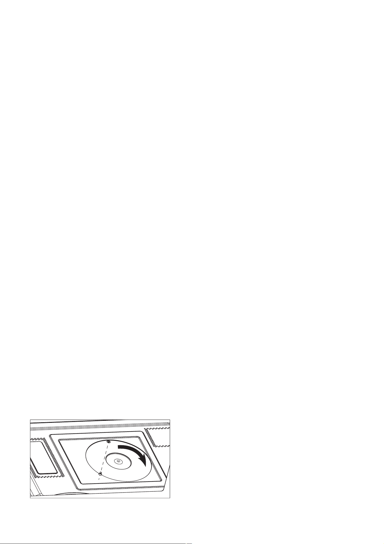
1. Disconnect the power supplier cord.
2. Open the door and block it open.
3. Remove the plastic nail with ’一’ driver.
4. Counterclockwise rotate the stirrer bracket.
5. Now the stirrer bracket and stirrer fan is free.
14. Stirrer Motor Removal
1 5 . Stirrer Bracket and Stirrer Fan Removal
16. Door Assembly Removal
1. Disconnect the power supply cord, remove oven
from wall, then remove outer case.
2. Open the door and block it open.
3. Discharge high voltage capacitor.
4. Remove the screw holding the control panel to the
oven cavity front plate.
5. Push up the control panel and remove it from cavity
and hold it at the front plate by the control panel flange.
6. Disconnect the wire leads from the control panel.
7. Remove the screw holding the hood motor to cavity
and remove the hood motor.
8. Remove thescrews from the air duct to cavity.
9.
Remove the screw from the air grid *R to cavity and
remove the air grid *R.
10. Remove the screws from the air duct to fan guide.
11. Remove the screws from the air duct to back wind
guide.
12. Remove the screw from power cord to back wind guide.
13. Remove the screw from earth connection of noise
filter to cavity.
14. Disconnect the wire leads from the air duct assembly.
15. Now, the air duct assembly is free.
16. Remove the screws from sensor humidity to air duct.
17. Now, the sensor humidity is free.
1 7 . Sensor Humidity Removal
7

Convection MMMMotor
1. Disconnect the power supply cord, remove oven
from wall, then remove outer case.
2. Open the door and block it open.
3. Discharge high voltage capacitor.
4. Disconnect the wire lead from convection motor.
5. Remove the belt.
6. Remove holding motor bracket
connector to the main wind guide.
7. Remove t holding motor bracket to
cavity.
8. Remove t holding the motor to the
motor bracket.
9. Remove one holding pulley to the motor.
10.
The
convection
motor
is
now
free.
Thermal Cut-Out (Convection) Removal
1. Disconnect the power supply cord, remove oven
from wall, then remove outer case.
2. Open the door and block it open.
3. Discharge high voltage capacitor.
4. Disconnect the wire lead from thermal cut-out.
5. Releast the thermal cut-out from the convection
6. Now,the thermal cut-out is free.
assembly.
the screws
he screws
he screws
nut
18.
19.
Removal
8
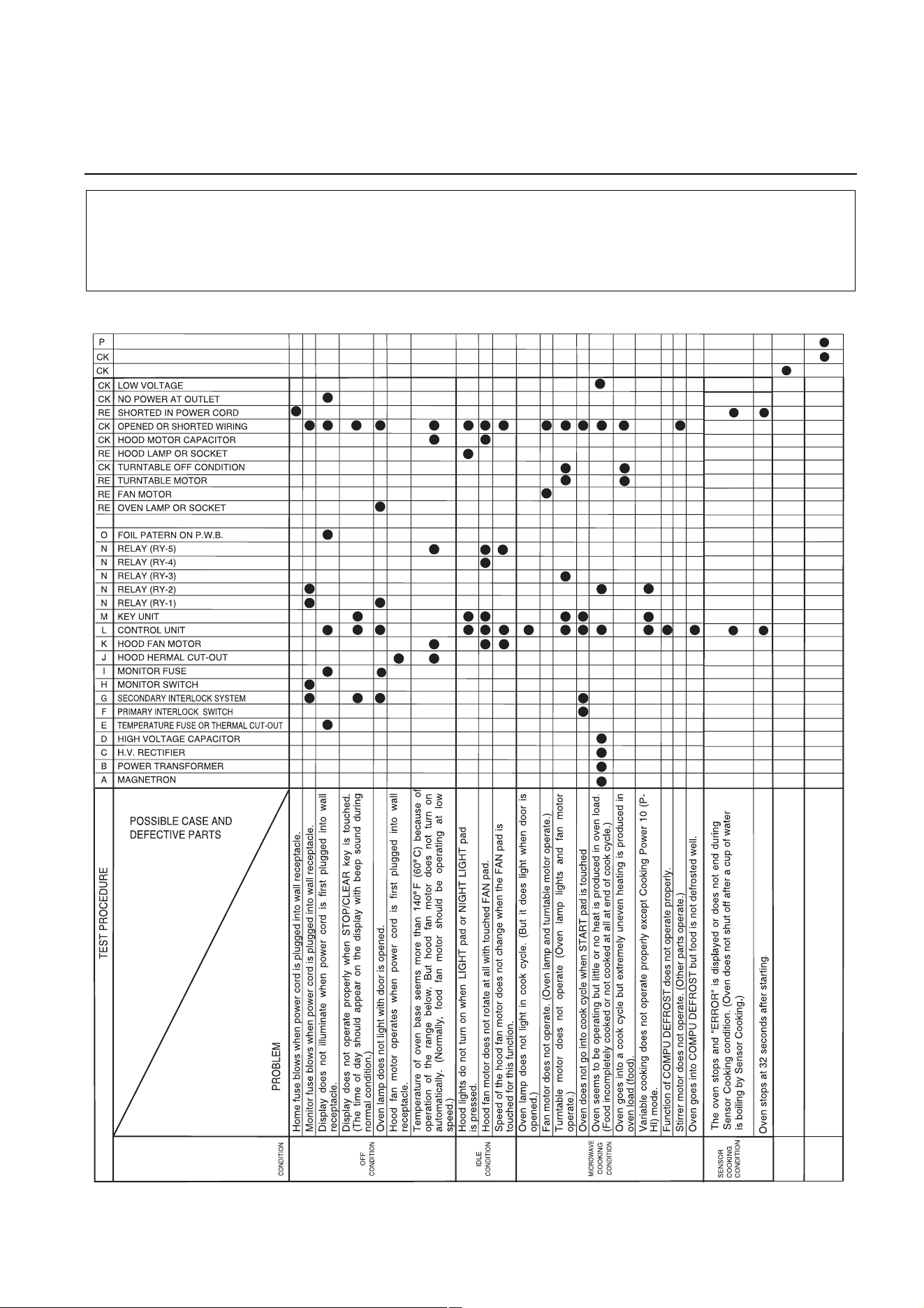
Troubleshooting Guide Chart
CONVECTION
Convection motor does not operate. (convection
heater and oven lamp operate)
CONDITION
Convection heater does not operate.(Food
incompletely cooked or not cooked at the end of
cook cycle.)
CONVECTION MOTOR
CONVECTION HEATER
CONVECTION THERMAL CUT-Ou t
CK = Check / RE = Replace
1. Check grounding before checking for trouble.
2. Be careful of the high voltage circuit.
3. Discharge the high voltage capacitor. (See page 2-1)
CAUTIONS
TROUBLESHOOTING AND TESTING
9
Test Procedures
Procedure
Letter
A
Component Test
MAGNETRON ASSEMBLY TEST
1. Disconnect the power supply cord, and then remove outer case.
2. Open the door and block it open.
3. Discharge high voltage capacitor.
4. To test for an open filament, isolate the magnetron from the high voltage circuit. A continuity
check across the magnetron filament leads should indicate less than 1 ohm.
5. To test for a shorted magnetron, connect the ohmmeter leads between the magnetron filament
leads and chassis ground. This test should indicate an infinite resistance. If there is little or no
resistance the magnetron is grounded and must be replaced.
6. Reconnect all leads removed from components during testing.
7. Reinstall the outer case (cabinet).
8. Reconnect the power supply cord after the outer case is installed.
9. Run the oven and check all functions.
MICROWAVE OUTPUT POWER
Power output of the magnetron can be measured by performing a water temperature rise test. This
test should only be used if above tests do not indicate a faulty magnetron and there is no defect in
the following components or wiring: silicon rectifier, high voltage capacitor and power transformer.
This test will require a 16 ounce (453 cc.) measuring cup and an accurate mercury thermometer or
thermocouple type temperature tester. For accurate results, the following procedure must be
followed carefully:
1. Fill the measuring cup with 16 oz. (453 cc.) of tap water and measure the temperature of
the water with a thermometer or thermocouple temperature tester. Stir the thermometer or
thermocouple through the water until the temperature stabilizes. Record the temperature of the
water.
2. Place the cup of water in the oven. Operate oven at 100% POWER selecting more than 60
seconds cook time. Allow the water to heat for 60 seconds, measuring with a stop watch,
second hand of a watch or the digital read-out countdown.
3. Remove the cup from the oven and again measure the temperature, making sure to stir the
thermometer or thermocouple through the water until the maximum temperature is recorded.
4. Subtract the cold water temperature from the hot water temperature. The normal result should
be 29.2 to 54.2°F (16.2 to 30.1°C) rise in temperature. If the water temperatures are accurately
measured and tested for the required time period the test results will indicate if the magnetron
tube has low power output (low rise in water temperature) which would extend cooking time or
high power output (high rise in water temperature) which would reduce cooking time. Because
cooking time can be adjusted to compensate for power output, the magnetron tube assembly
should be replaced only if the water temperature rise test indicates a power output well beyond
the normal limits. The test is only accurate if the power supply line voltage is 120 volts and the
oven cavity is clean.
High voltages are present during the cook cycle, so extreme caution should be
observed. Discharge the high voltage capacitor before touching any oven components
or wiring.
WARNING
10
Procedure
Letter
B
C
Component Test
POWER TRANSFORMER TEST
1. Disconnect the power supply cord, and then remove outer case.
2. Open the door and block it open.
3. Discharge high voltage capacitor.
4. Disconnect the primary input terminals and measure the resistance of the transformer with an
ohmmeter. Check for continuity of the coils with an ohmmeter. On R x 1 scale, the resistance of
the primary coil should be less than 1 ohm and the resistance of the high voltage coil should be
approximately 83 ohms; the resistance of filament coil should be less than 1 ohm.
5. Reconnect all leads removed from components during testing.
6. Reinstall the outer case (cabinet).
7. Reconnect the power supply cord after the outer case is installed.
8. Run the oven and check all functions.
HIGH VOLTAGE RECTIFIER TEST
1. Disconnect the power supply cord, and then remove outer case.
2. Open the door and block it open.
3. Discharge high voltage capacitor.
4. Isolate the rectifier from the circuit. Using the highest ohm scale of the meter, read the
resistance across the terminals and observe, reverse the leads to the rectifier terminals and
observe meter reading. If a short is indicated in both directions, or if an infinite resistance is
read in both directions, the rectifier is probably defective and should be replaced.
5. Reconnect all leads removed from components during testing.
6. Reinstall the outer case (cabinet).
7. Reconnect the power supply cord after the outer case is installed.
8. Run the oven and check all functions.
Do not touch the components of the
power transformer
while
power transformer
is
energized. It is dangerous because this has high voltage components. (High voltages
are present at the high voltage terminal, so do not attempt to measure the fi lament
and high voltage.)
WARNING
Be sure to use an ohmmeter that will supply a forward bias voltage of more than 9.0 volts.
NOTE
Test Procedures
11
Procedure
Letter
D
E
Component Test
HIGH VOLTAGE CAPACITOR TEST
1. Disconnect the power supply cord, and then remove outer case.
2. Open the door and block it open.
3. Discharge high voltage capacitor.
4. If the capacitor is open, no high voltage will be available to the magnetron. Disconnect input
leads and check for short or open between the terminals using an ohmmeter.
Checking with a high ohm scale, if the high voltage capacitor is normal, the meter will indicate
continuity for a short time and should indicate an open circuit once the capacitor is charged. If
the above is not the case, check the capacitor with an ohmmeter to see if it is shorted between
either of the terminals and case. If it is shorted, replace the capacitor.
5. Reconnect all leads removed from components during testing.
6. Reinstall the outer case (cabinet).
7. Reconnect the power supply cord after the outer case is installed.
8. Run the oven and check all functions.
CAVITY THERMAL CUT-OUT TEST
1. Disconnect the power supply cord, and then remove outer case.
2. Open the door and block it open.
3. Discharge high voltage capacitor.
4. A continuity check across the thermal cut-out terminals should indicate a closed circuit
unless the temperature of the thermal cut-out reaches approximately 302°F(150°C). An
open thermal cut-out indicates overheating of the oven, exchange thermal cut-out and check
inside of oven cavity for improper setting of cooking time or operation of control unit. Check for
restricted air flow through the vent holes of the oven cavity, especially the cooling fan and air
guide.
5. Reconnect all leads removed from components during testing.
6. Reinstall the outer case (cabinet).
7. Reconnect the power supply cord after the outer case is installed.
8. Run the oven and check all functions.
MAGNETRON TEMPERATURE FUSE TEST
1. Disconnect the power supply cord, and then remove outer case.
2. Open the door and block it open.
3. Discharge high voltage capacitor.
4. A continuity check across the magnetron temperature fuse terminals should indicate a closed
circuit unless the temperature of the magnetron temperature fuse reaches approximately 302°F
(150°C). An open magnetron temperature fuse indicates overheating of the magnetron. Check
for restricted air flow to the magnetron, especially the cooling fan air guide.
5. Reconnect all leads removed from components during testing.
6. Reinstall the outer case (cabinet).
7. Reconnect the power supply cord after the outer case is installed.
8. Run the oven and check all functions.
If the temperature fuse indicates an open circuit at room temperature, replace
temperature fuse.
CAUTION
Test Procedures
12
Procedure
Letter
F
G
Component Test
PRIMARY INTERLOCK SWITCH TEST
1. Disconnect the power supply cord, and then remove outer case.
2. Open the door and block it open.
3. Discharge high voltage capacitor.
4. Isolate the switch and connect the ohmmeter to the common (COM.) and normally open (NO)
terminal of the switch. The meter should indicate an open circuit with the door open and a
closed circuit with the door closed. If improper operation is indicated, replace the primary
interlock switch.
5. Reconnect all leads removed from components during testing.
6. Reinstall the outer case (cabinet).
7. Reconnect the power supply cord after the outer case is installed.
8. Run the oven and check all functions.
PRIMARY INTERLOCK SYSTEM TEST
DOOR SENSING SWITCH
1. Disconnect the power supply cord, and then remove outer case.
2. Open the door and block it open.
3. Discharge high voltage capacitor.
4. Isolate the switch and connect the ohmmeter to the common (COM.) and normally open (NO)
terminal of the switch. The meter should indicate an open circuit with the door open and a
closed circuit with the door closed. If improper operation is indicated, replace the door sensing
switch.
5. Reconnect all leads removed from components during testing.
6. Reinstall the outer case (cabinet).
7. Reconnect the power supply cord after the outer case is installed.
8. Run the oven and check all functions.
SECONDARY INTERLOCK RELAY (RY2)
1. Disconnect the power supply cord, and then remove outer case.
2. Open the door and block it open.
3. Discharge high voltage capacitor.
4. Disconnect two (2) wire leads from the male tab terminals of the Secondary Interlock Relay.
Check the state of the relay contacts using an ohmmeter. The relay contacts should be open.
If the relay contacts are closed, replace the circuit board entirely.
5. Reconnect all leads removed from components during testing.
6. Reinstall the outer case (cabinet).
7. Reconnect the power supply cord after the outer case is installed.
8. Run the oven and check all functions.
If the door sensing switch contacts fail in the open position and the door is closed, the
cooling fan, turntable and oven light will be activated by RY1.
CAUTION
Test Procedures
13
Component Test
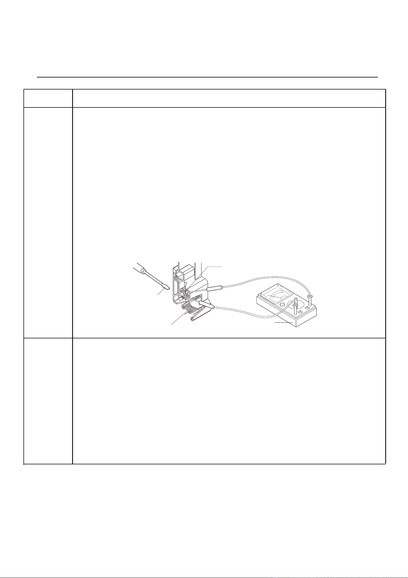
MONITOR SWITCH TEST
1. Disconnect the power supply cord, and then remove outer case.
2. Open the door and block it open.
3. Discharge high voltage capacitor.
4. Before performing this test, make sure that the secondary interlock switch and the primary
interlock relay are operating properly, according to the Switch Test Procedure. Disconnect the
wire lead from the monitor switch (COM) terminal. Check the monitor switch operation by
using the ohmmeter as follows. When the door is open, the meter should indicate a closed
circuit. When the monitor switch actuator is pushed by a screwdriver through the lower latch
hole on the front plate of the oven cavity with the door opened (in this condition the plunger of
the monitor switch is pushed in), the meter should indicate an open circuit. If improper
operation is indicated, the switch may be defective. After testing the monitor switch, reconnect
wire lead to monitor switch (COM) terminal and check continuity of monitor circuit.
5. Reconnect all leads removed from components during testing.
6. Reinstall the outer case (cabinet).
7. Reconnect the power supply cord after the outer case is installed.
8. Run the oven and check all functions.
HOOD THERMAL CUT-OUT TEST
1. Disconnect the power supply cord, and then remove outer case.
2. Open the door and block it open.
3. Discharge high voltage capacitor.
4. A continuity check across the thermal cut-out terminals should indicate an open circuit unless the
temperature of the thermal cut-out reaches approximately 158°F (70°C) or more. At that
temperature, the contacts will close. The thermal cut-out opens automatically at approximately
104°F (40°C).
5. Reconnect all leads removed from components during testing.
6. Reinstall the outer case (cabinet).
7. Reconnect the power supply cord after the outer case is installed.
8. Run the oven and check all functions.
Procedure
Letter
H
J
Door
Sensing Switch
Monitor Switch
Screwdriver
Ohmmeter
Test Procedures
14
Component Test
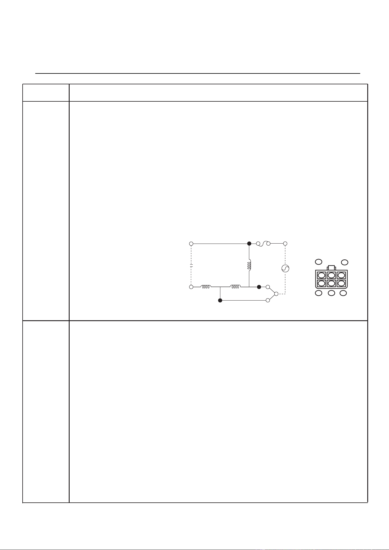
HOOD FAN MOTOR TEST
1. Disconnect the power supply cord, and then remove outer case.
2. Open the door and block it open.
3. Discharge high voltage capacitor.
4. If the motor does not turn, touch the FAN button once and check voltage between pins “1” and
“2” (Black and Blue wires) of the 6 pin connector. If 120 Volts appear and the hood capacitor
is good, replace the hood fan assembly. If 120 Volts does not appear, check the motor circuit.
The resistance values of motor terminals are as follows:
5. Reconnect all leads removed from components during testing.
6. Reinstall the outer case (cabinet).
7. Reconnect the power supply cord after the outer case is installed.
8. Run the oven and check all functions.
TOUCH CONTROL PANEL ASSEMBLY TEST
The touch control panel consists of circuits including semiconductors such as LSI, ICs, etc.
Therefore, unlike conventional microwave ovens, proper maintenance cannot be performed with only
a voltmeter and ohmmeter. In this service manual, the touch control panel assembly is divided into
two units, Control Unit and Key Unit, and troubleshooting by unit replacement is described
according to the symptoms indicated.
Before testing,
1. Disconnect power supply cord, and remove outer case.
2. Open the door and block it open.
3. Discharge high voltage capacitor.
4. Remove two (2) screws holding the hood intake duct R to the oven cavity top plate and the
base
plate R. And remove the hood intake duct R.
5. Disconnect the leads to the primary of the power transformer.
6. Ensure that these leads remain isolated from other components and oven chassis by using
insulation tape.
Continued on next page.
Procedure
Letter
K
L
Test Procedures
15
WHT (1) AND YLW (4) = 0Ω (Shorted)
BLU (2) AND YLW (4) = 34Ω
WHT (1) AND BLK (2) = 34Ω
RED (5) AND WHT(1) = 77Ω
RED (5) AND BLU (2) = 43Ω
YLW (4) AND RED (5) = 77Ω
6-pin Connector
Of Hood Fan Motor
RED YLW
ORG BLU WHT
5
3
2
1
4
OR (Low)
RD
SUB
CON
Main
BL (Hi)
120V
60Hz
WH
T/P
YW
Cap.
10µF
Procedure
Letter
Component Test
KEY UNIT NOTES:
1. Check key unit ribbon connection before replacement.
2. Reconnect all leads removed from components during testing.
3. Re-install the hood intake duct R with two (2) screws.1. Re-install the outer case (cabinet).
4. Reconnect the power supply cord after the outer case is installed.
5. Run the oven and check all functions.
The following symptoms indicate a defective key unit.
a) When touching the pads, a certain pad produces no signal at all.
b) When touching a number pad, two figures or more are displayed.
c) When touching the pads, sometimes a pad produces no signal.
If the key unit is defective.
1. Disconnect the power supply cord, and then remove outer case.
2. Open the door and block it open.
3. To discharge high voltage capacitor, wait for 60 seconds.
4. Replace the key unit.
5. Reconnect all leads removed from components during testing.
6. Re-install the outer case (cabinet).
7. Reconnect the power supply cord after the outer case is installed.
8. Run the oven and check all functions.
CONTROL UNIT
The following symptoms indicate a defective control unit. Before replacing the control unit, perform
the Key unit test (Procedure M) to determine if control unit is faulty.
1. In connection with pads.
a) When touching the pads, a certain group of pads do not produce a signal.
b) When touching the pads, no pads produce a signal.
2. In connection with indicators.
a) At a certain digit, all or some segments do not light up.
b) At a certain digit, brightness is low.
c) Only one indicator does not light.
d) The corresponding segments of all digits do not light up; or they continue to light up.
e) Wrong figure appears.
f) A certain group of indicators do not light up.
g) The figure of all digits flicker.
3. Other possible problems caused by defective control unit.
a) Buzzer does not sound or continues to sound.
b) Clock does not operate properly.
c) Cooking is not possible.
When testing is completed,
1. Disconnect the power supply cord.
2. Open the door and block it open.
3. Discharge high voltage capacitor.
4. Reconnect all leads removed from components during testing.
5. Re-install the hood intake duct R.
6. Re-install the outer case (cabinet).
7. Reconnect the power supply cord after the case is installed.
8. Run the oven and check all functions.
Test Procedures
16
Procedure
Letter
M
Component Test
KEY UNIT TEST
1. Disconnect the power supply cord, and then remove outer case.
2. Open the door and block it open.
3. Discharge high voltage capacitor.
4. Remove the control panel assembly.
5. If the display fails to clear when the CANCEL pad is depressed, first verify the flat ribbon
cable is making good contact, verify that the door sensing switch (stop switch) operates
properly; that is the contacts are closed when the door is closed and open when the door is
open. If the door sensing switch (stop switch) is good, disconnect the flat ribbon cable that
connects the key unit to the control unit and make sure the door sensing switch is closed
(either close the door or short the door sensing switch connector). Use the Key unit matrix
indicated on the control panel schematic and place a jumper wire between the pins that
correspond to the CANCEL pad making momentary contact. If the control unit responds
by clearing with a beep the key unit is faulty and must be replaced. If the control unit does
not respond, it is faulty and must be replaced. If a specific pad does not respond, the above
method may be used (after clearing the control unit) to determine if the control unit or
key pad is at fault.
5. Reconnect all leads removed from components during testing.
6. Re-install the outer case (cabinet).
7. Reconnect the power supply cord.
8. Run the oven and check all functions.
Test Procedures
17
Procedure
Letter
Q
Component Test
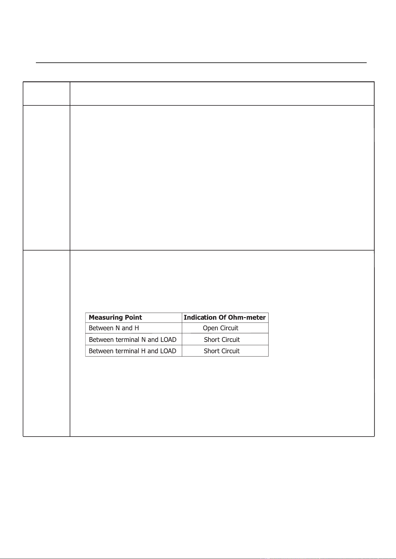
NOISE FILTER TEST
1. Disconnect the power supply cord, and then remove outer case.
2. Open the door and block it open.
3. Discharge high voltage capacitor.
4. Disconnect the leads to the primary of the power transformer.
5. Using an ohm-meter, check between the terminals as described in the following table:
If incorrect readings are obtained,
replace the noise filter.
6. Reconnect all leads removed from
components during testing.
7. Re-install the outer case (cabinet).
8. Reconnect the power supply cord
after the outer case is installed.
9. Run the oven and check all functions.
DEFROST CENTER TE
ST
1. Open the door.
2. Place one cup of water in the center of the turntable tray in the oven cavity.
3. Close the door.
4. Touch the “DEFROST” pad once.
Touch the “ START “ button.
The oven is in Defrost Center cooking condition.
.
O
Test Procedures
18
Touch the number pad “ .5”
5.
6.
7.
8.
Touch the “ START “ button.

ATTACHED FILES LIST
1. Exploded View 2. Spare Parts List 3. Wiring Diagram
* Note: The manual may update without prior notice. Please download the latest version on
website: https://tsp.midea.com.
19