READ CAREFULLY.
KEEP THESE INSTRUCTIONS
.
Installation Over the Range
Instructions M icrow ave Oven
Read these instructions completely and carefully.
•
IMPORTANT –
Save these
instructions for local inspector’s use.
•
IMPORTANT –
Observe all
governing codes and ordinances.
•
Note to Installer –
Be sure to leave these
instructions with the Consumer.
BEFORE YOU BEGIN
• Note to Consumer – Keep these
instructions for future reference.
• Skill level – Installation of this appliance requires
basic mechanical and electrical skills.
• Proper installation is the responsibility of the installer.
• Product failure due to improper installation is not
covered under the Warranty.
or
Questions? Call
X -XXX-XXX-XXXX(US)
X-XXX-XXX-XXXX(Canada)
January 2022
p/n A06823415

CONTENTS
General information
Important Safety Instructions .................................. 3
Electrical Requirements .......................................... 3
Damage – Shipment/Installation.............................. 4
Parts Included.......................................................... 4
Tools You Will Need ................................................ 5
Mounting Space ...................................................... 5
Step-by-step installation guide
6–8
Removing the Mounting Plate ...................... 6
Finding the Wall Studs .................................. 6
Determining Wall Plate Location .................. 7
Aligning the Wall Plate ................................ 8
Adapting Microwave Blower
B
Installation Instructions
Recirculating ...........................................
Mount the Microwave Oven ................18
Preparation of Top Cabinet ................16
Attach Mounting Plate to Wall ............16
Outside Back Exhaust..........................15
Outside Back Exhaust............................ 15–18
Placement of The Mounting Plate
......................
Preparing Rear Wall for
Remove Blower Plate ............................ 15..
Charcoal Filter
Installing or Change the
Preparation of Top Cabinet ...................
Check Blower Plate ...............................
..................................12-13
Attach Mounting Plate to Wall ...............
–
Installation Types............................................... .....9
for Outside Back Exhaust................16 –17
Mount the Microwave Oven ............11
–
A
10 13
10
11
11
12
Outside Top Exhaust
Attach Mounting Plate to Wall............19
Preparation of Top Cabinet................20
Checking for Proper Damper
Connecting Ductwork..........................22
Adjust the Exhaust Adaptor ................22
Operation............................................21
Adapting Microwave Blower for
Outside top Exhaust
.................. 20-21
............................ 19-22
Mount the Microwave Oven
.........21-22
C
Before You Use Your Microwave.......................... 23
Hood Exhaust
.................................................... 13-14
EN-2
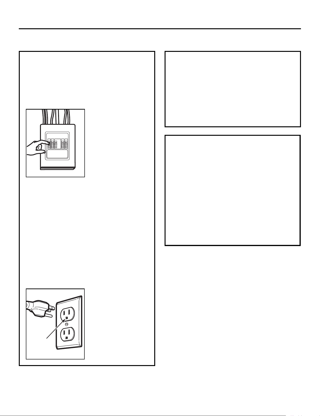
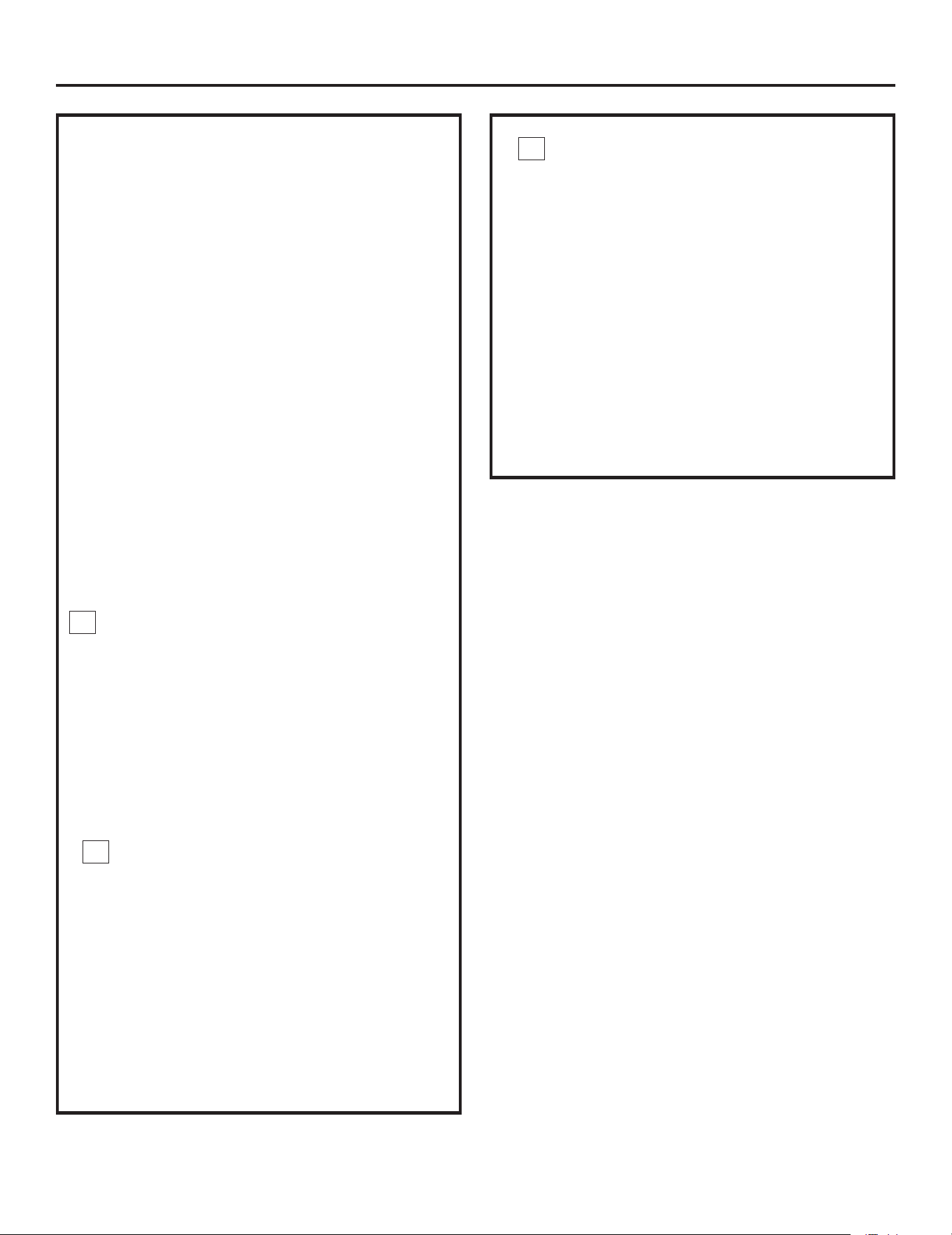
This product requires a three-prong grounded outlet.
The installer must perform a ground continuity check
on the power outlet box before beginning the
installation to ensure that the outlet box is properly
grounded. If not properly grounded, or if the outlet
box does not meet electrical requirements noted
(under ELECTRICAL REQUIREMENTS), a qualified
electrician should be employed to correct any
deficiencies.
CAUTION: For personal
safety, remove house fuse
or open circuit breaker
before beginning
installation to avoid severe
or fatal shock injury.
CAUTION: For personal safety, the mounting surface
must be capable of supporting the cabinet load, in
addition to the added weight of this 63–85 pound
(28.5–38.5 kg) product, plus additional oven loads of
up to 50 pounds (22.7 kg) or a total weight of
113–135 pounds (51.3–61.2 kg).
CAUTION: For personal safety, this product cannot
be installed in cabinet arrangements such as an island or
a peninsula. It must be mounted to BOTH a top cabinet
AND a wall.
NOTE: For easier installation and personal safety, it is
recommended that two people install this product.
IMPORTANT – PLEASE READ CAREFULLY. FOR
PERSONAL SAFETY, THIS APPLIANCE MUST BE
PROPERLY GROUNDED TO AVOID SEVERE OR
FATAL SHOCK.
The power cord of this
appliance is equipped with a
three-prong (grounding)
plug which mates with a
standard three-prong
(grounding) wall receptacle
to minimize the possibility
of electric shock hazard
from this appliance.
You should have the wall receptacle and circuit checked
by a qualified electrician to make sure the receptacle is
properly grounded.
Where a standard two-prong wall receptacle is
encountered, it is very important to have it replaced
with a properly grounded three-prong wall receptacle,
installed by a qualified electrician.
DO NOT, UNDER ANY CIRCUMSTANCES, CUT,
DEFORM O R REMOVE ANY OF THE PRONGS
FROM THE POWER CORD. DO NOT USE WITH
AN EXTENSION CORD.
IM PORTANT SAFETY INSTRUCTIONS
Ensure proper
ground exists
before use
Installation Instructions
ELECTRICAL
REQUIREM ENTS
Product rating is 120 volts AC, 60 Hertz, 15 amps and
1.6 kilowatts. This product must be connected to a
The power supply cord and plug should be brought to a
the prevailing local code for this kilowatt rating.
the requirements of the National Electrical Code or
voltage and frequency. Wire size must conform to
seperate and dedicated supply circuit of the proper
seperate and dedicated 15- to 20- ampere branch
National Electrical Code or the prevailing local code.
by a qualifed electrician and conform to the
The outler box and supply circuit should be installed
be located in the cabinet above the microwave oven.
circuit single grounded outlet. The outlet box should
EN-3
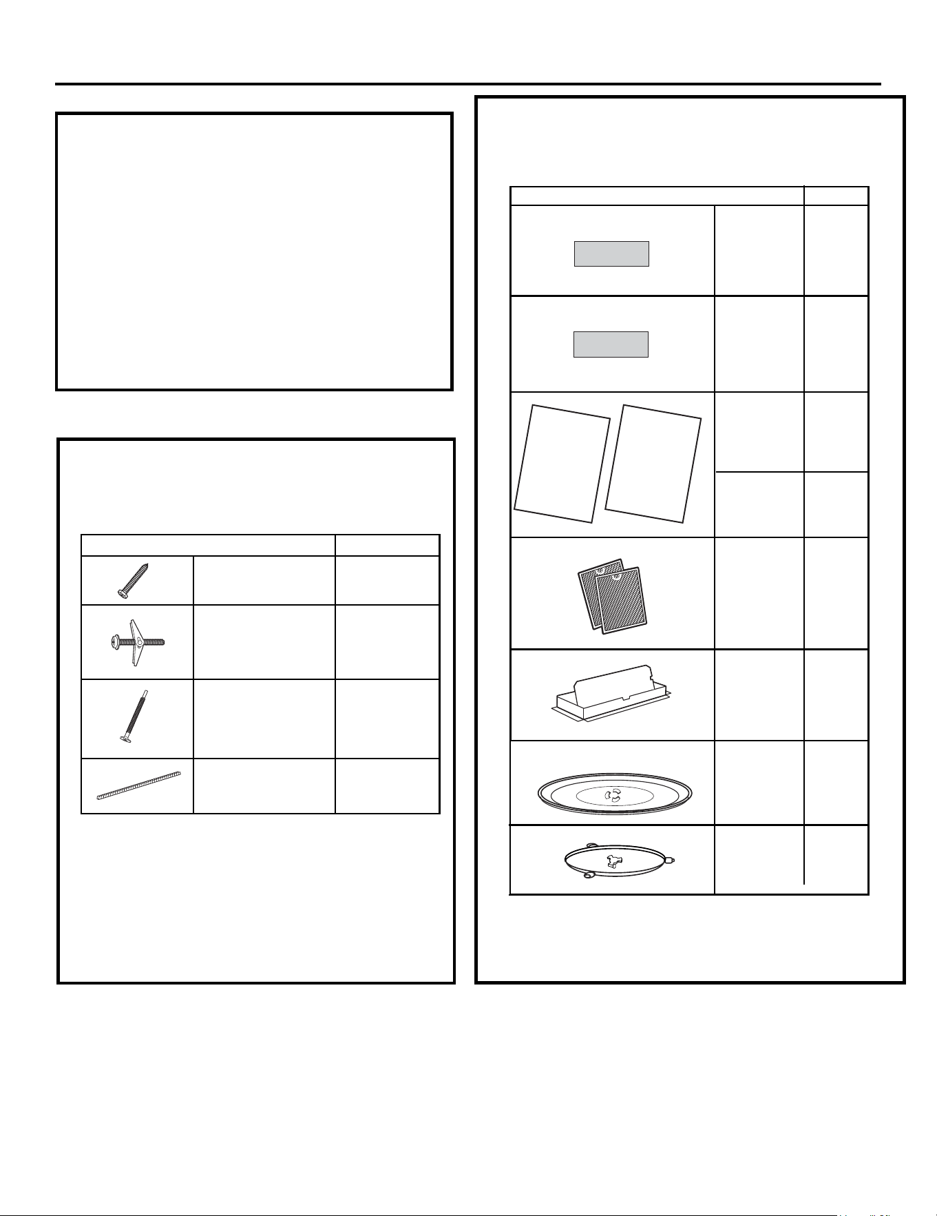
YTITNAUQTRAP
Wood Screws 2
(
1
⁄4“ x 2“)
Toggle Bolts (and
wing nuts) (
3
⁄16“ x 3“)
Self-Aligning Machine 3
Screws (
1
⁄4“-28 x 3
1
⁄4“)
Nylon Grommet
(for metal cabinets)
1
• If the unit is damaged in shipment, return the
unit to the store in which it was bought for repair
or replacement.
• If the unit is damaged by the customer,repair or
replacement is the responsibility of the customer.
• If the unit is damaged by the installer (if other
than the customer), repair or replacement must
be made by arrangement between customer
and installer.
DAMAGE—SHIPMENT/
INSTALLATION
Installation Instructions
PARTS INCLUDED
You will find the installation hardware contained in
a packet with the unit. Check to make sure you have
all these parts.
NOTE: Some extra parts are included.
HARDWARE PACKET
PART
QUANTITY
Template
1
Template
Installation
1
Instructions
Separately
2
Packed
Filters
PARTS INCLUDED
(CONT.)
INSTALLATION
INSTRUCTIONS
ADDITIONAL PARTS
1
adaptor
Grease
Exhaust
Glass
1
Tray
1
Ring
elbatnurT
CabinetTop
Rear
Wall
2
1
Use & Care
1
USE & CARE
MANUAL
Manual
EN-4
Installation Instructions
• Tape measure
• Hole saw
• Stud finder or hammer
• Level
• Duct and masking tape
• Scissors
• #1 Phillips screw driver
• Electric drill
• 3/16”, 1/2”, 5/8” drill bit
• Filler wood blocks for recessed
bottom cabinets
• Tin snips
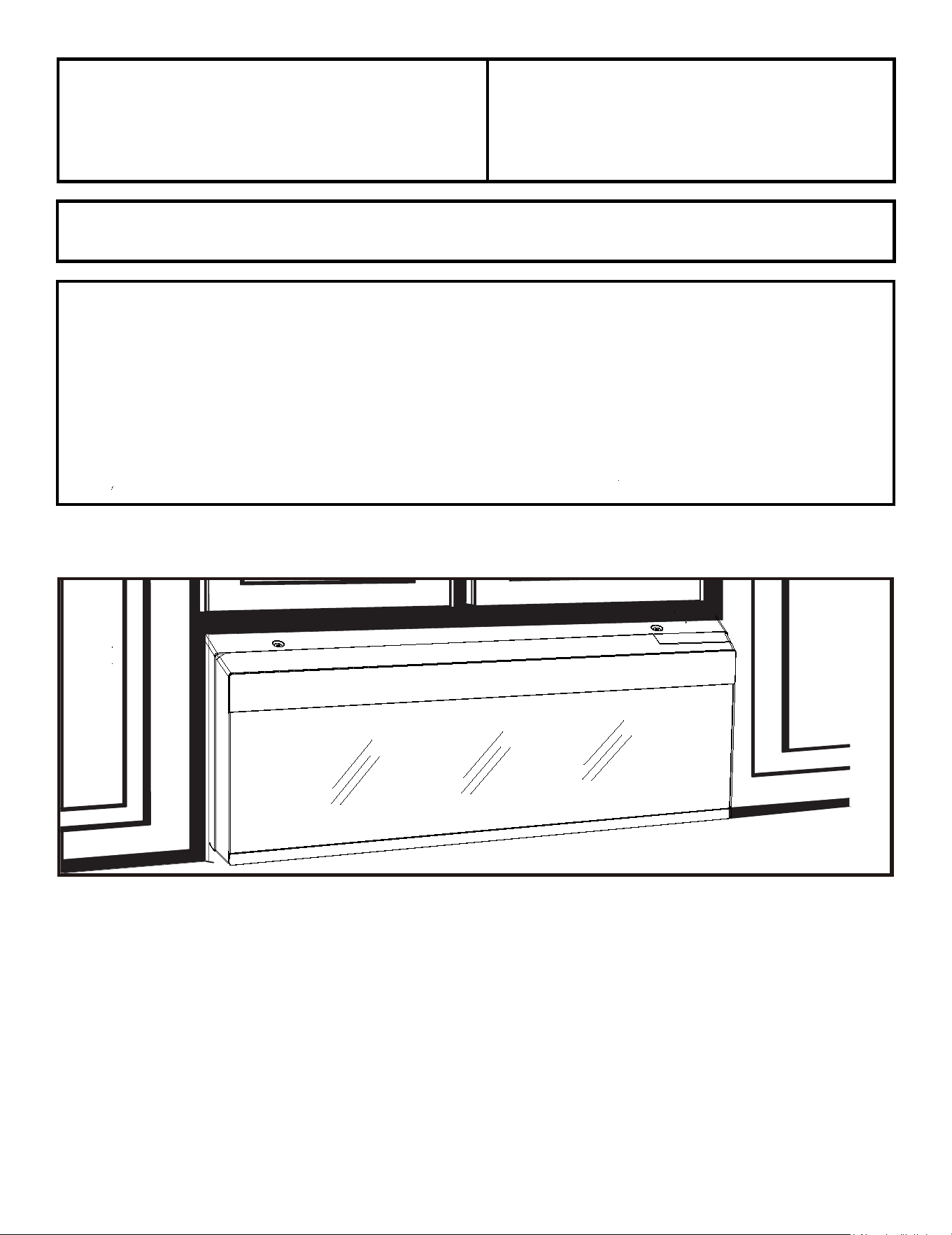
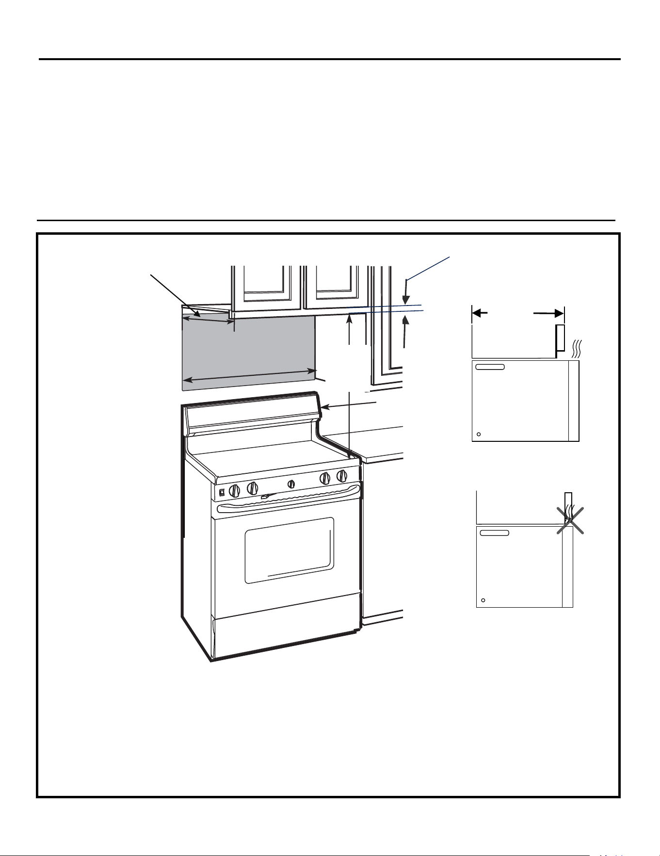
Mounting Space
Tools you will need:
• The space between the cabinets must be 30" (76.2 cm) wide and free of obstructions.
• If you are going to vent your microwave oven to the outside, see Hood Exhaust Section for exhaust
duct preparation
• When installing the microwave oven beneath smooth, flat cabinets, be careful to follow the
instructions on the top cabinet template for power cord clearance.
• As a guide to installation, see page 26 for Mounting Template Information.
• If the cabinet depth, including the cabinet doors, is more than 13.8”, then the unit must be spaced out
from wall using adequate materials supporting 150 lbs to allow proper top vent air exhaust/intake.
¼" Min
13.8" Max
(35 cm)
Backsplash
30
24
(61cm)
min.
Cabinet
Cabinet
Clearance
(35 cm)
13.8" MAX.
"(76.2 cm)
"
EN-5
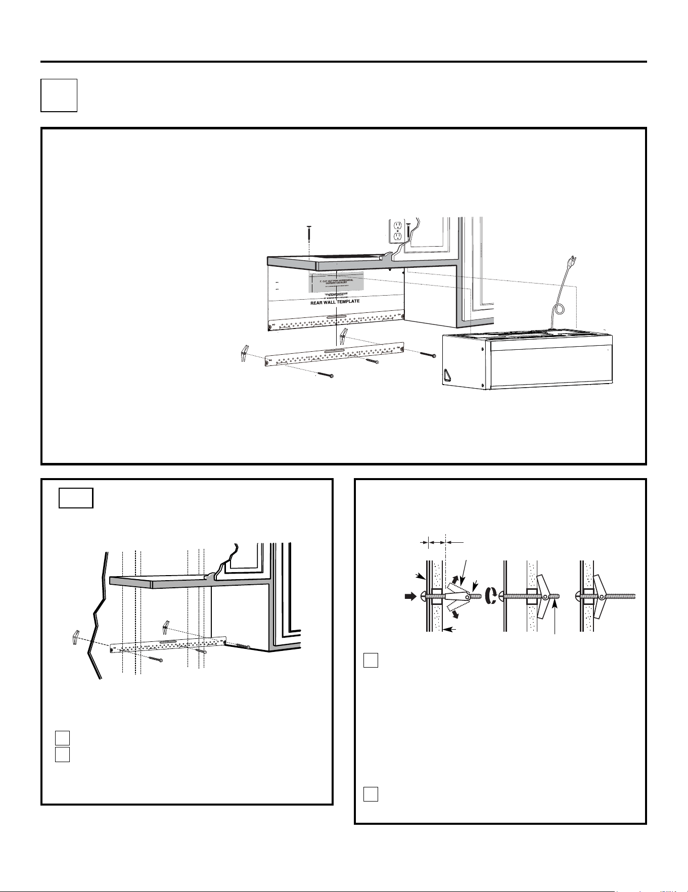
PLACEMENT OF THE MOUNTING PLATE
1
Installation Instructions
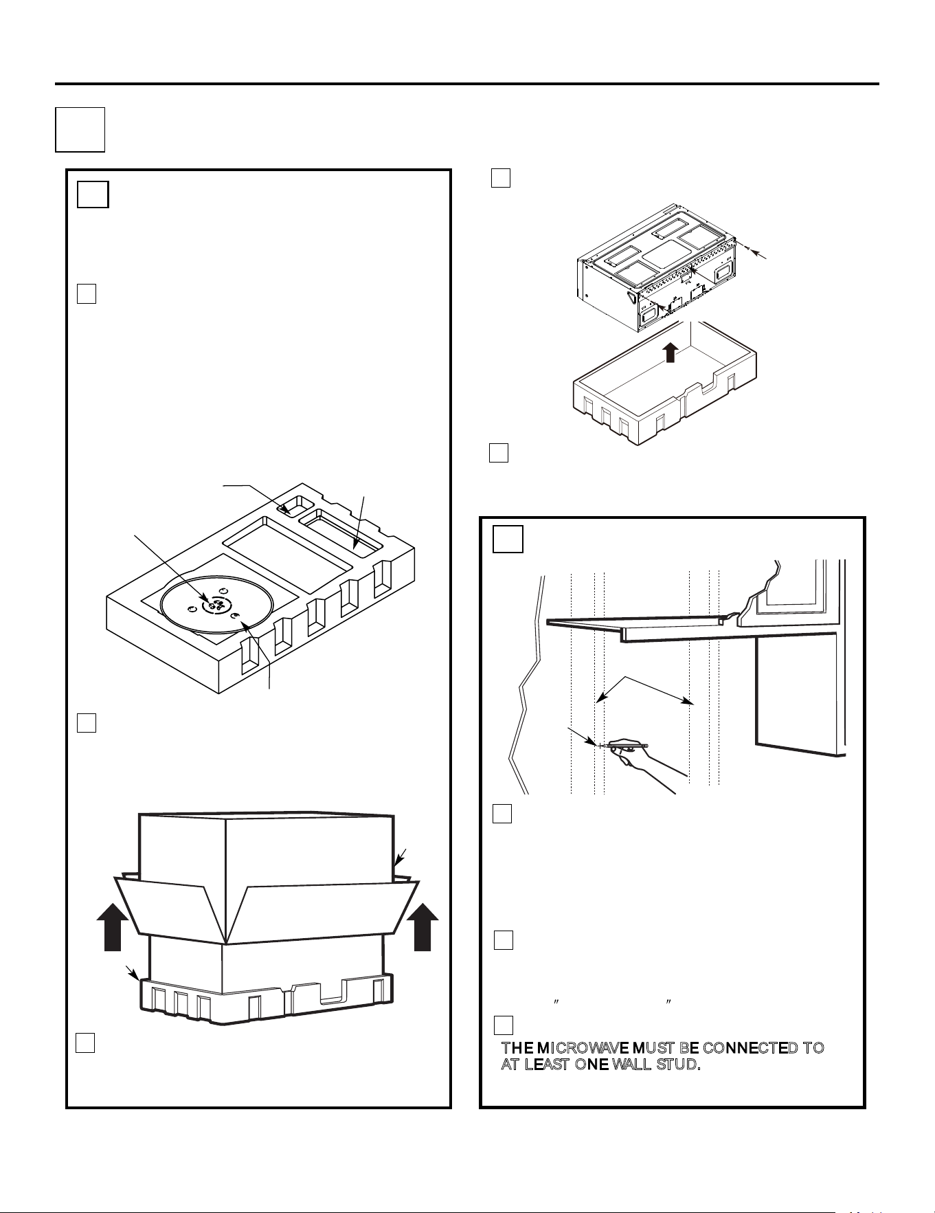
Find the studs, using one of the following
methods:
A. Stud finder – a magnetic device which
locates nails.
B. Use a hammer to tap lightly across the
mounting surface to find a solid sound.
This will indicate a stud location.
After locating the stud(s), find the center by
probing the wall with a small nail to find the edges
of the stud. Then place a mark halfway between
the edges. The center of any adjacent studs should
be 16
(40.6 cm) or 24 (61 cm) from this mark.
Draw a line down the center of the studs.
T
HE MICROWAVE MUST BE CONNECTED TO
AT LEAST ONE WALL STUD.
1
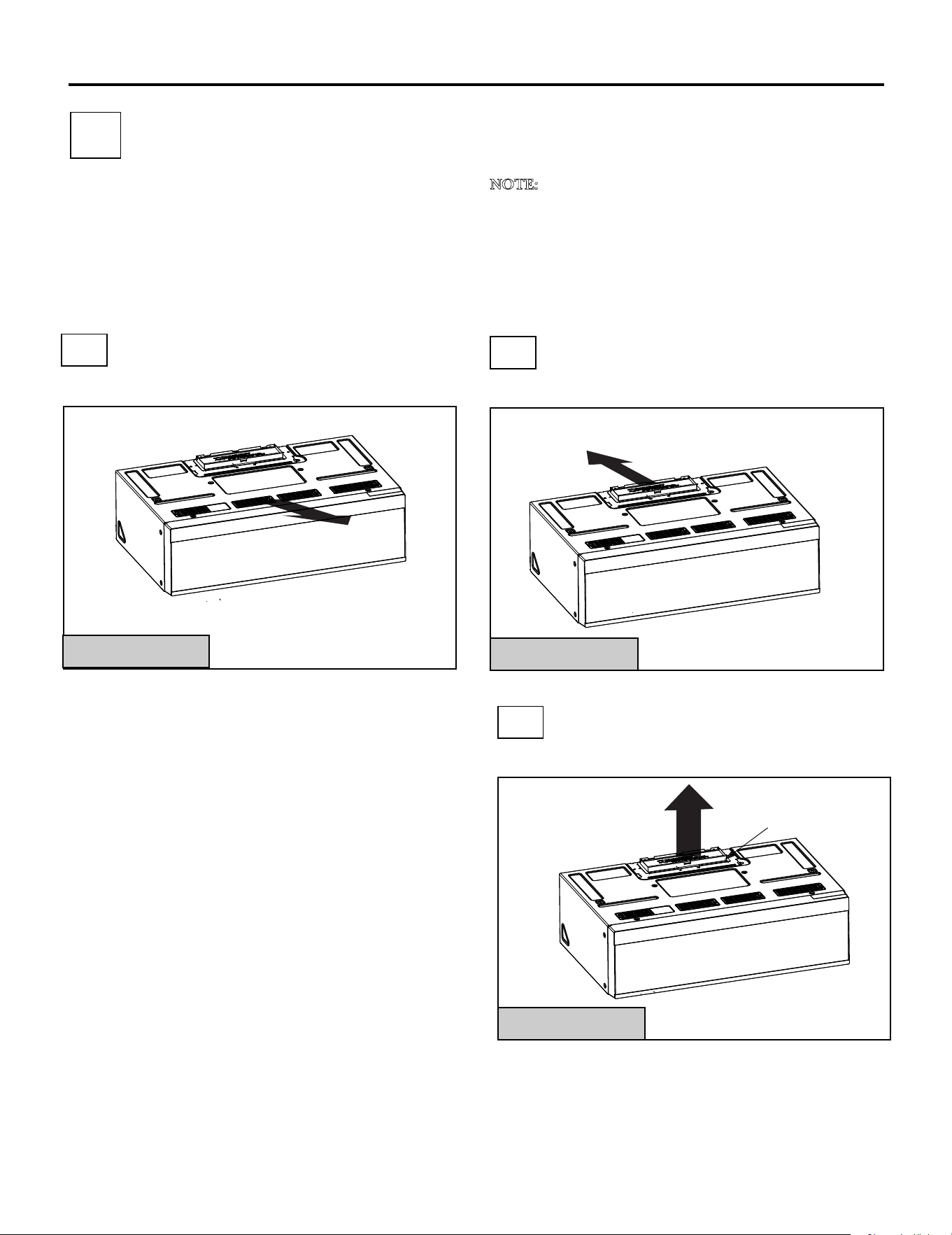
Fold back all 4 carton flaps fully against carton
sides. Then carefully roll the oven and carton over
onto the top side. The oven should be resting in
the Styrofoam.
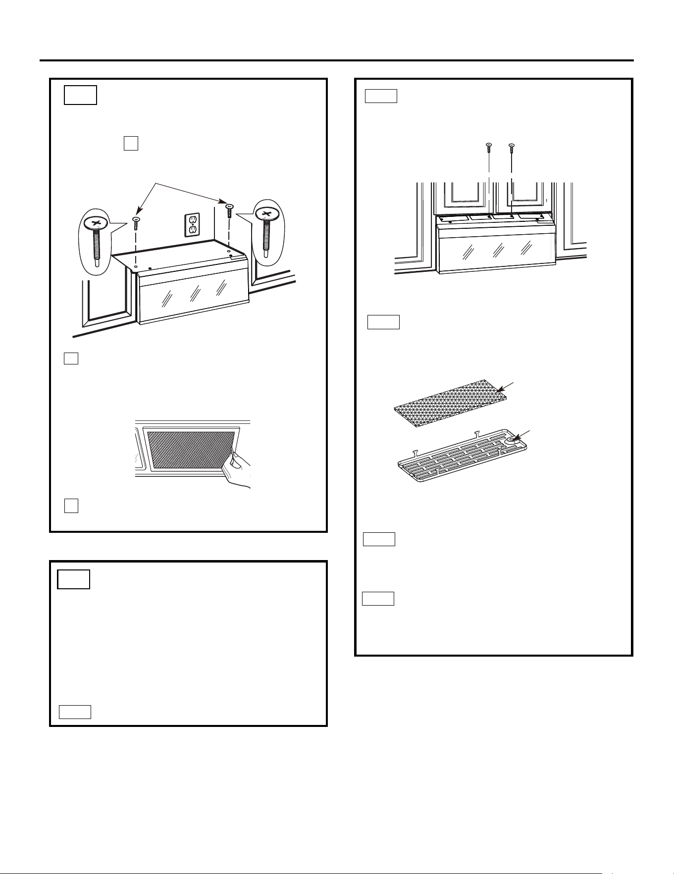
REMOVING THE MICROWAVE
OVEN FROM THE CARTON/
REMOVING THE MOUNTING
PLATE
FINDING THE WALL STUDS
B
.
A
.
2
Wall
Studs
Center
3
Carton
Pull the carton up and off the oven.
2
Styrofoam
3
1
Screws
Mounting Plate
5
4
Cut the middle of the outer protective plastic bag to
r
emove
the
ounting late
m
p
Remove the installation instructions,use and care,
exhaust adapter, turntable ring, filters, glass
Do not remove
the Styrofoam protecting the top of the oven.
Remove the screws from each end of the mounting
plate. This plate will be used as the rear wall template
ba
g.
and for mounting. Reinstall the screws into the holes
where they were removed.
tray
and the small hardware
please note: Do Not Remove plastic plug
EN-6
protective cover until just before hanging the unit.
Filters and Turntable
Ring below glass tray
Exhaust Adapter
Small Hardware Bag
Glass Tray
Keep the unit at least 8 inches away from the
counter top edge to prevent dropping because
of the heavy door.
Screws
DETERMINING WALL PLATE LOCATION UNDER YOUR CABINET
C.
Installation Instructions
Plate position flat bottom
cabinet
to Cooktop
C
3
/
8
"
T
O
EDGE
N
OT
E: IT IS VERY IMP
OR
TANT TO
RE
A
D
AND F
O
LLOW
T
H
E
DIRE
CTIONS
IN
T
H
E
INST
ALL
ATION
INSTRUCT
IO
N
S
BE
F
O
R
E
P
ROCEE
DING WIT
H
T
H
IS
RE
A
R W
ALL
TEMP
L
A
TE.
This
Rear Wall T
e
mpla
t
e
s
er
ve
s
t
o
p
ositio
n
t
he bo
tto
m
moun
tin
g
plate
and
to lo
ca
t
e
t
h
e
ho
ri
zontal
e
xh
aust
outlet.
1.
Use
a
level
t
o check t
h
a
t
the
templat
e
is p
os
it
ione
d
a
c
c
u
rat
e
ly.
2
.
L
ocate an
d m
ar
k
at
lea
s
t
o
n
e stud o
n the le
f
t
o
r
right
side
o
f th
e
c
e
n
ter
lin
e
.
It
is
imp
ort
a
nt
to u
se at
le
a
st
o
ne wood
sc
re
w
mou
n
t
e
d
f
ir
mly in a stud to s
u
p
port the w
eight
of
th
e
m
icrowave. M
ark t
w
o additiona
l,
ev
e
nly
s
paced
lo
c
at
ion
s
f
or
t
h
e
s
upplied
t
o
ggle
bolt
s
.
3
.
D
rill
h
oles
in
the
m
a
rke
d
loc
a
t
ions
.
Whe
re
th
e
re
is
a stud, drill a
3
/1
6
" ho
le for
w
ood s
c
rews
. F
or ho
les
that
do n
ot
li
ne up with
a
s
t
ud
,
dri
ll
5/8"
hole
s
for
t
o
g
g
le
bolt
s.
D
O NOT INS
TALL
T
H
E MO
U
N
T
IN
G P
L
ATE
AT
TH
IS TIME.
4
.
R
e
m
o
ve
the tem
p
lat
e
f
rom t
h
e r
e
a
r wall.
5. R
e
view t
he
In
s
ta
llation
I
nst
r
u
ction book
f
o
r
yo
ur
ins
tallation
situ
at
io
n
.
L
o
c
a
t
e
an
d
ma
rk h
o
l
es
to ali
g
n w
ith hol
e
s
i
n the
mo
u
n
t
i
ng
p
l
a
te
.
IMP
ORTANT:
LO
CATE
A
T
LEAST ON
E
S
T
U
D ON EI
T
H
ER
SIDE
O
F
T
HE C
E
N
TE
R
LIN
E.
MA
R
K T
H
E
L
OC
A
T
ION
FO
R
2
A
D
D
IT
I
O
N
AL,
E
VE
NLY
SP
A
C
E
D TOGG
L
E B
OL
T
S IN
THE MOUN
TING P
L
AT
E
ARE
A
.
Lo
cate a
n
d
ma
rk
ho
les
to
a
l
ign w
ith h
o
l
es in
t
he
mount
i
n
g
p
l
a
te.
IMP
O
RTA
N
T
:
LOCA
T
E AT
L
EAST ON
E
S
T
U
D ON EITH
E
R SID
E O
F
T
H
E
CEN
T
E
RLIN
E
.
MA
R
K
THE
LOC
ATION
F
OR
2 A
D
D
IT
IONAL
,
E
V
E
N
LY
S
PAC
E
D
TO
GG
L
E
B
OLT
S
IN T
H
E MO
U
N
T
IN
G
P
LATE
AR
E
A.
T
r
im
th
e r
ear w
a
l
l
te
m
p
late
alo
ng the do
tte
d
lin
e.
Tr
im th
e
r
ear wa
ll
te
m
pl
a
te
a
lo
n
g
th
e
d
o
tte
d
l
in
e
.
12"
4
"
D
a
rle
vu
e
lt
a a
la
ho
ja
pa
ra
c
o
nsu
lt
a
r la
vers
ió
n
en E
spaño
l.
3/8
"
TO EDGE
NO
TE
: IT IS
VER
Y
IMPOR
T
ANT T
O
READ
AND FO
LLO
W THE D
IREC
TIO
NS
I
N
T
H
E
INST
ALLATIO
N
INST
RUCTI
O
N
S
BEFO
RE PR
O
CEEDING
W
ITH THI
S
R
EAR W
AL
L
T
EMPL
AT
E.
This R
ear Wall Temp
late serves
to posit
io
n
the
b
o
t
to
m
mou
ntin
g
plate
and to loc
at
e
the ho
r
iz
ontal e
x
h
aust
outle
t.
1.
Us
e a
level to c
he
ck
th
at th
e
template is
positioned
ac
cu
rately
.
2. Loca
te and mar
k
a
t leas
t
one s
t
u
d
on the left or
r
ight
s
ide o
f
th
e cente
rline.
It
is impor
tant to use at least one
wo
od
s
c
r
e
w mounted
firmly in
a stud
to
s
u
pport the we
ig
ht
of
the mic
r
ow
ave. Ma
r
k two
additional, eve
nly spaced
lo
c
atio
ns fo
r th
e
s
upp
lied toggle
bolts
.
3.
Drill holes in
the ma
rked loc
ation
s.
Whe
re there is
a
stud, drill
a 3
/1
6" ho
le fo
r w
o
od sc
rews
. For ho
le
s
that do n
ot lin
e
u
p
with a s
tud,
dr
ill 5
/8" holes for
tog
gle bolts.
D
O NOT INSTALL TH
E
MOUNTING PLATE
AT THIS TIME.
4. Re
m
ov
e
the templa
te
from the rear
w
all.
5. Re
v
ie
w
the Installation
In
stru
c
tion
boo
k fo
r your
in
stallatio
n
s
ituation.
Locate an
d
ma
rk
holes to align wit
h
holes
i
n t
h
e
mo
unting
pla
t
e
.
IM
PORT
ANT
:
LOC
ATE AT LEAST
ONE STUD
ON
EITH
ER SI
D
E OF
THE CENTER
LINE.
MAR
K T
HE LOC
ATIO
N
FOR
2
ADD
I
T
IONAL, EVEN
L
Y
SPAC
ED
T
OG
GLE BO
LT
S I
N TH
E MOUNTI
NG
PLATE
AR
EA.
Lo
cate
an
d
ma
rk
hol
es t
o al
ign w
i
t
h
h
ol
es
in t
h
e
mo
un
tin
g pl
a
t
e.
IMPO
RTANT:
LOC
ATE AT
LEAS
T ON
E ST
U
D ON EI
T
HER SID
E
O
F
THE
C
EN
TE
R
LINE
.
MARK T
HE LOCATION
F
O
R 2 AD
DI
TIONAL
, EVENL
Y
SPA
C
E
D
T
O
G
GLE
BOL
T
S I
N
TH
E
MOUN
TI
N
G
P
LATE
AR
EA.
Trim
th
e
r
ear
wall t
emplat
e
a
long
the
dotted
li
ne.
Trim
the
r
ear wal
l
tem
plate a
l
ong
the
dotted
li
ne.
12"
4"
Darle
v
u
el
t
a
a
la
ho
ja
para co
ns
ult
ar
la
versió
n
e
n Español.
A
t
l
e
a
s
t
3
0
″
C
3/8" T
O
ED
G
E
N
O
T
E: I
T
I
S
VER
Y IMPORTANT TO
REA
D
A
ND F
OL
LOW
THE DIREC
TIONS
I
N
T
HE
I
NS
TAL
L
ATIO
N
I
N
S
TRU
C
TION
S
B
EF
O
RE PROC
EEDI
N
G
W
I
TH
TH
I
S
R
E
AR
WALL
T
EMP
LAT
E
.
T
h
is
Rear
W
a
l
l Template se
rves to p
os
ition
the b
otto
m
mou
nti
ng pla
t
e and to locate the
h
o
rizontal exh
au
st
o
utlet.
1. Use a leve
l to ch
e
ck t
hat the template is posi
tion
ed
a
ccu
r
a
tely.
2
. Loca
te a
nd
mark at least o
ne stu
d o
n the
l
eft o
r
rig
ht sid
e
of the
centerline.
It is importa
nt to u
se
at le
a
st one wo
o
d
scre
w
mo
u
nted fi
rmly in
a
stud to support the weig
ht
o
f t
he
m
icrow
ave. Mark two
a
d
diti
o
nal
, e
venly
sp
aced
locations f
or t
h
e
supplied
toggle
b
olts.
3
. Drill holes in t
h
e
m
arked loca
t
ion
s.
Where there
is
a
stud, drill a 3/16" h
o
le
for
wo
od scr
e
w
s.
Fo
r holes
t
h
at do not lin
e
u
p
wit
h
a stu
d, drill 5/8" holes
fo
r
togg
le
bolt
s
.
DO N
OT
INST
A
L
L
T
HE
MOUNT
ING PLATE
AT T
H
IS
T
IME.
4
. Remo
ve the
temp
la
te fro
m the
rea
r wall.
5
.
Revi
e
w the I
nstallati
o
n
In
struction bo
ok for
your
insta
llation
situation.
Locate and m
ark h
oles
t
o
al
ign
with ho
les
in t
he
m
o
unting
plate
.
I
M
P
O
RT
A
N
T:
LOC
ATE
A
T LE
A
ST ON
E
STUD ON EITH
E
R
S
I
DE
OF
TH
E
CE
N
TERLINE.
M
A
R
K TH
E
LOCATION
F
OR 2
A
D
D
I
TION
AL, EV
EN
L
Y
S
P
A
C
ED
TOGGL
E BOLT
S IN THE
M
OU
N
T
I
N
G P
LAT
E
A
REA.
Loc
ate
a
nd
m
ar
k holes
t
o
align
w
i
th holes
i
n
t
he
m
o
u
nt
i
ng plat
e
.
I
MPORTAN
T:
LO
CAT
E AT
LEA
S
T
ON
E
S
T
U
D ON
E
ITH
ER
SIDE OF
TH
E
CE
N
TE
R
LINE.
M
A
RK
TH
E
LOC
A
T
I
O
N F
OR
2 A
DDI
TI
ONAL,
E
V
E
NLY
SPA
C
ED
TOGGLE
B
OL
TS
IN THE MOUNTIN
G
P
LATE
AREA.
T
r
im
th
e
re
a
r wall
te
m
pl
ate
al
ong
th
e
d
o
tted
li
n
e.
T
rim th
e
r
ear
wal
l
t
emplate
a
l
o
n
g
th
e
dotte
d li
ne.
12"
4
"
Da
rle
vuelta a la
hoja para
c
ons
ultar
la
v
ersión
e
n
Espa
ñol.
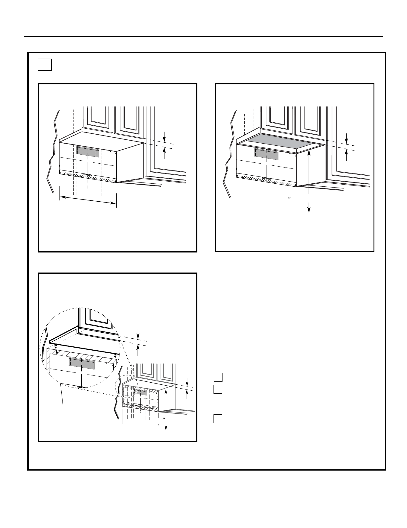
Your cabinets may have decorative trim that
interferes with the microwave installation. Remove
the decorative trim to install the microwave properly
and to make it level.
THE MICROWAVE MUST BE LEVEL.
Use a level to make sure the cabinet bottom is level.
If the cabinets have a front overhang only, with no
back or side frame, install the mounting plate down
the same distance as the front overhang depth. This
will keep the microwave level.
Measure the inside depth of the front overhang.
Draw a horizontal line on the back wall an equal
distance below the cabinet bottom as the inside
depth of the front overhang.
For this type of installation with front overhang
only, align the mounting tabs with this horizontal
line, not touching the cabinet bottom as described
in Step D.
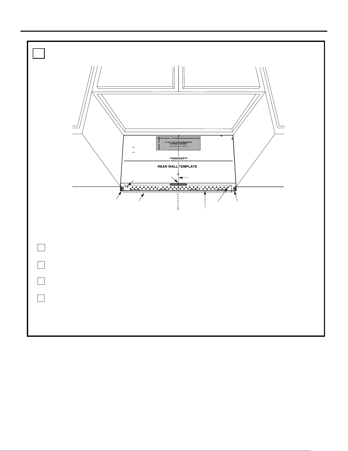
Draw a vertical line on
the wall at the center of
the 30
″ wide space.
Tape the Rear Wall
Template onto the wall
matching the centerline
and touching the
bottom of the cabinet.
to Cooktop
Draw a vertical line on the wall at the center of the
30
″ space.
Tape the Rear Wall Template onto the wall
matching the centerline and touching the bottom
C
3/
8
"
TO ED
G
E
NOT
E:
I
T
I
S VERY
IMPORT
AN
T
TO
RE
A
D
A
ND
FO
LLOW T
HE
DIRE
CTIONS
IN THE INSTALLA
TION I
NS
TRU
CT
IONS
BE
F
OR
E PR
OC
EED
I
NG
WI
T
H THIS
REAR WA
LL
TEMPL
ATE
.
Th
i
s
R
ear
Wa
ll Te
mpl
at
e
ser
ves to
p
o
sition the bot
tom
mount
i
ng
p
l
ate and
t
o
locate th
e
hor
i
z
on
tal
exh
a
u
st
o
u
tl
e
t
.
1. Use a level
to
che
ck th
a
t
the
temp
late is p
osit
i
one
d
a
c
cura
tely.
2
.
Locate
and
mar
k at le
a
st o
n
e stu
d on
the left or
ri
gh
t
side of
the
c
enterl
i
ne.
It
is impo
r
ta
nt to u
se
a
t
l
ea
s
t
on
e
wo
od
screw mo
u
n
t
ed fir
ml
y in
a
stud
t
o su
p
po
rt
the we
ight
of th
e mi
cr
o
w
ave. Mark
tw
o add
i
ti
o
nal
,
e
venly spa
ced
loca
ti
o
ns for the suppli
ed
t
og
gle bolts.
3. Dril
l
holes in
the marked lo
ca
t
io
n
s. Whe
re there
i
s
a
stud, d
ril
l a 3/
1
6"
ho
le for
w
oo
d scr
ew
s. For hol
es
that
do
not lin
e
up w
i
t
h
a
st
ud, d
rill 5/8" h
ole
s fo
r
t
o
gg
l
e b
ol
t
s
.
DO
NOT
INSTALL THE
M
OUNTI
NG
PLA
T
E
AT
T
H
IS TIM
E.
4. R
e
move the
te
mplate fr
o
m t
he rear wall.
5. R
eview
the
I
n
stallatio
n
Instruction boo
k f
o
r yo
ur
in
stallation
situat
io
n
.
Locat
e and
ma
rk
hol
es
to al
i
gn
with
h
oles in
the
mo
unti
ng
plate.
I
MPO
RT
AN
T
:
LOCA
TE
A
T LEAST
ONE
S
T
UD
ON EI
T
HE
R
S
I
DE
OF
THE
CEN
T
ER
LINE.
MARK THE
LOCATI
O
N F
O
R 2 A
D
DITIONA
L, E
VE
NLY
SP
A
CED TOGGLE
B
OLT
S
I
N
THE
M
OUNT
I
NG
PLATE
A
R
EA.
Loc
ate
and mark holes
t
o a
l
ign
wit
h
hole
s
in the
mo
unt
i
ng pl
at
e
.
IMPORTANT:
LOCAT
E
AT
LEAS
T
ONE
STUD ON
EITHE
R SID
E
OF
T
HE
CE
NTERL
I
NE.
MARK T
H
E LOCATION
F
OR
2
A
DD
I
T
I
O
NA
L,
EV
ENL
Y
SPA
CED TOGG
LE
B
O
LT
S
I
N
THE
MOUNTING
P
L
A
T
E
A
REA.
Trim
the
rear wa
l
l
templ
ate
al
on
g th
e
dott
e
d
lin
e.
T
rim t
h
e
rear w
all
templ
ate
a
l
on
g
t
h
e
do
tt
ed
line.
12"
4"
Darl
e
v
uelta a la
ho
ja
para con
s
ult
a
r
la
versió
n
en
E
s
p
año
l.
cabinet bottom
with front overhang
Plate position framed
recessed
Plate position
bottom
1
3
2
24
cabinet frame.
24
-beneath
-beneath
-beneath recessed
cabinet
1/4"
Minimum
clearance
1/4"
Minimum
clearance
1/4"
Minimum
clearance
Draw a line on the
back wall equal to the
depth of the front
overhang.
1/4"
Minimum
clearance
EN-7
Installation Instructions
ALIGNING THE WALL PLATE
D.
Area E
Hole A
Hole B
Centerline
notches
Draw a Vertical Line
on Wall from Center
of Top Cabinet
Draw a horizontal line on wall at the
bottom of “Rear Wall Template”.
Horizontal Line
Horizontal Line
C
L
3/8" TO EDGE
NOTE: IT IS VERY IMPORTANT TO
READ AND FOLLOW THE DI
RECTIONS
IN THE INSTALLATION INSTRUCTIONS
BEFORE PROCEEDI
NG WITH
THIS
REAR WALL TEMPLATE.
This Rear Wal
l Template serves t
o position the bottom
mounting plate and to locate
the horizontal exhaust
outlet.
1. Use a level to check th
at the template is positioned
accurately.
2. Locate and ma
rk at least one stud on the left or
right side of the centerlin
e.
It is important to use at least one wood
screw mounted firmly in a stud to s
upport the weight
of the microwave. Mark two add
itional, evenly spaced
locations for the supp
lied toggle bolts.
3. Drill holes in the marked locatio
ns. Where there is
a stud, drill a 3/16" hole for
wood screws. For hole
s
that do not line up with a st
ud, drill 5/8" holes for
toggle bolts.
DO NOT INSTALL THE M
OUNTING PLATE
AT THIS TIME.
4. Remove the tem
plate from the rear wall.
5. Review the Installation Instru
ction book for your
installation situation.
Locate and mark
holes to align with h
oles in the
mounting plat
e.
IMPORTANT:
LOCATE
AT LEAST ONE
STUD ON EITHER SIDE OF
THE CENTERLINE.
MARK THE LOCATION FOR 2
ADDITIONAL, EVENLY
SPACED
TOGGLE BOLTS IN
THE MOUNTING PLATE
AREA.
Locate and mark
holes to align with hol
es in the
mounting plat
e.
IMPORTANT:
LOCATE
AT LEAST ONE
STUD ON EITHER SIDE OF
THE CENTERLINE.
MARK THE LOCATION FOR 2
ADDITIONAL, EVENLY
SPACED
TOGGLE BOLTS IN
THE MOUNTING PLATE
AREA.
Trim the rear
wall template al
ong the dotted
line.
12"
4"
Darle vuelta a la hoja para consultar la
versión en Español.
Draw a vertical line on the wall at the center of the
30" wide space.
NOTE: DO NOT MOUNT THE PLATE AT THIS
TIME.
NOTE: Holes A and B are inside area E. If neither of
important to have at least one wood screw mounted
firmly in a stud to support the weight of the
microwave. Set the mounting plate aside.
1
2
Draw a horizontal line on the wall at the bottom of
“Rear Wall Template”.
Holes A and B are not in a stud, find a stud somewhere
in area E and draw a circle to line up with the stud. It is
3
Find a wall stud in area "E" of mounting plate
Refer to section 1B. Finding the wall studs.
For attaching the mounting plate into stud drill
a 3/16" hole into wood stud. Drill a 5/8" hole for
toggle bolt in 1 other location (Hole A or Hole B)
4
EN-8
INSTALLATION TYPES
This microwave oven is designed for adaptation to
the following three types of ventilation:
B. Outside Back Exhaust (Horizontal Duct)
proceed to that section.
OUTSIDE TOP EXHAUST
(VERTICAL DUCT)
OUTSIDE BACK EXHAUST
(HORIZONTAL DUCT)
See page 20
Adaptor in Place for
Outside Top Exhaust
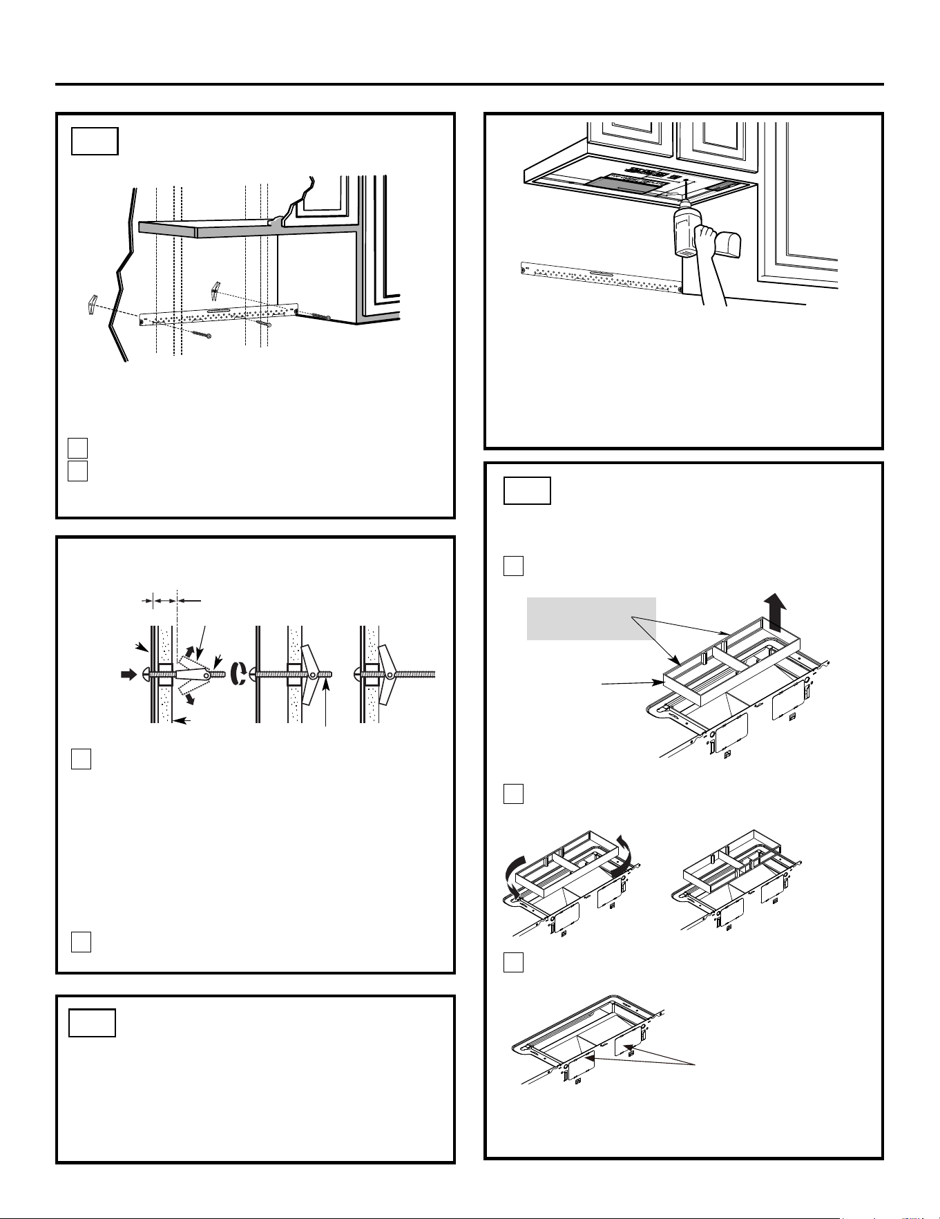
2
B
Adaptor Must Be
Moved to the Back for
Outside Back Exhaust
N
OTE: This microwave is shipped assembled for
Recirculating. Select the
type of ventilation required
(Choose A,Bor C)
for your installation and
Installation Instructions
outside. If you plan to recirculate the air back into the room, proceed to page 10.
A. Recirculating (Non-Vented Ductless)
C. Outside Top Exhaust (Vertical Duct)
C
RECIRCULATING
(NON-VENTED DUCTLESS)
recirculating exhaust.
disposable charcoal filter
installed to help remove
smoke and odors.
See page 10
Models are shipped for
Some models have a
A
EN-9
NOTE: Read the pages 14-15 only if you plan to vent your exhaust to the
See page 16
INSTALLATION OVERVIEW
Attach Mounting Plate to Wall
Prepare Top Cabinet
Mount the Microwave Oven
IMPORTANT NOTES:
• Make sure the screws for the blower motor and blower
plate are securely tightened when they are reinstalled.
This will help to prevent excessive vibration.
• Make sure the motor wiring has been properly routed
and secured, and that the wires are not pinched.
Installation Instructions
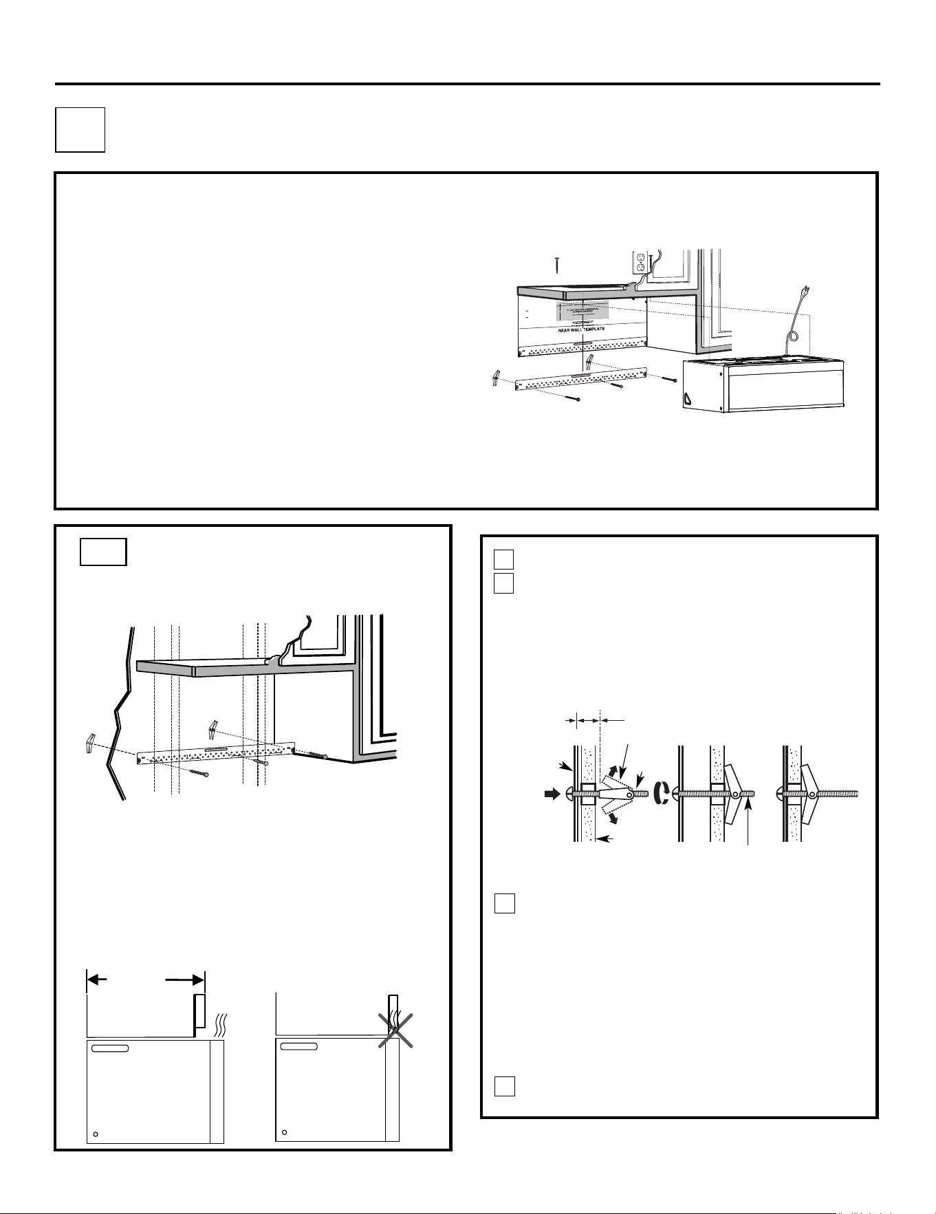
Place the mounting plate against the wall and
insert the toggle wings into the holes in the wall
to mount the plate.
NOTE: Before tightening toggle bolts and wood
screw, make sure the bott m of the mounting plate
touch the bottom of the cabinet when pushed flush
against the wall and that the plate is properly
centered under the cabinet.
CAUTION:Be careful to avoid pinching fingers
between the back of the mounting plate and the wall.
Tighten all bolts. Pull the plate away from the wall
to help tighten the bolts.
4
3
ATTACH THE MOUNTING
PLATE TO THE WALL
Attach the plate to the wall using toggle bolts.
At least one wood screw must be used to attach
the plate to a wall stud.
Remove the toggle wings from the bolts.
Insert the bolts into the mounting plate through
the holes designated to go into drywall and
reattach the toggle wings to
3
⁄4″(19 mm) onto
each bolt.
1
Wall
Mounting
Plate
Spacing for Toggles
More Than Wall
Thickness
Bolt End
Toggle
Bolt
Toggle Wings
To use toggle bolts:
2
RECIRCULATING (Non-Vented Ductless)
Install or change Charcoal Filter
Check Blower Plate
NOTE:
If the cabinet depth including the cabinet doors
decaps eb tsum tinu eht neht ''""31 naht erom si
o
A
A1.
A2.
A3.
A4.
A5.
A1.
Cabinet
Cabinet
(35 cm)
13.8" MAX.
out from wall using adequate materials supporting
150 Ibs to allow proper top vent air exhaust/intake.
EN-10
3/8"TO
EDG
E
N
O
TE
: IT IS VERY I
M
P
O
R
TA
NT TO
READ AND F
OLLO
W
THE
D
I
R
E
CTIO
NS
IN THE
I
NS
T
ALLA
T
ION I
NS
TR
U
CTIO
N
S
B
E
F
ORE
P
R
O
CEEDING
W
I
TH T
H
IS
RE
AR W
A
LL
TEM
P
L
AT
E
.
T
hi
s
R
e
ar
Wa
ll
Te
mpl
a
t
e
serves to po
s
iti
o
n
th
e
b
otto
m
mou
n
tin
g pl
ateand to l
o
cate t
h
e
h
or
i
z
o
n
ta
l
ex
haust
out
l
e
t.
1
.
U
s
e
a
le
velto
ch
eck t
h
at th
e
t
empla
te
is p
os
itioned
accuratel
y
.
2.
L
oca
te a
ndm
ark at le
a
s
t onestu
d
on theleft or
right
side of the c
e
nterlin
e
.
It is impo
rt
an
t t
o
use at l
e
as
t o
ne
w
ood
s
c
r
e
w
mou
nted fi
rmly in a
s
tud to suppor
t th
e weight
ofth
e micr
ow
ave
.
Mark two addi
tional, evenlyspa
c
ed
locatio
n
s for the
supplied toggle
bo
lts.
3. Dr
i
ll h
o
le
s in
the
marked
locations.Whe
r
e t
he
re is
a stu
d
, d
r
ill
a
3/
1
6"
h
ole
f
or
woo
d scr
e
ws
. For hole
s
thatd
o
not
line upw
ith
a s
tu
d, dril
l 5
/8" h
o
le
s fo
r
t
o
gg
le
bo
lts.
D
O
NO
T IN
STAL
L T
HE
MO
U
N
T
ING
PLA
TE
AT
T
H
IS
T
IM
E
.
4. Re
move th
e
te
mp
late
fr
omthe
rear
wall.
5.
R
ev
ie
h
t
w e In
sta
ll
a
tion
I
ns
t
r
uc
tio
n book f
or
y
ou
r
in
stallatio
n
s
itu
at
i
on
.
Locate and ma
rk
holes to align
wi
th
ho
les
i
n
t
h
e
mo
u
nti
ngp
l
a
te.
IMPO
RT
ANT
:
LO
C
AT
E
A
T L
EA
ST
ON
E
STUD
ON EIT
H
ER
S
ID
E O
F
T
H
E
CENT
E
RLIN
E
.
MARKT
HE LO
CATIO
N
FO
R
2
ADD
ITIO
N
AL, EVEN
LY
S
P
A
CE
D
TOGGLE BO
L
T
S
I
N
THE MO
U
NTING
PLATE
A
R
EA
.
Locate and mar
k
h
oles to ali
gn wit
h hol
es
in the
.
e
t
a
l
p
g
n
it
n
u
o
m
IMPO
RTANT
:
LO
CA
T
E
A
T L
EAS
T ON
E
ST
UD ON EITHE
R
SID
E
O
F
THE
CENTER
LIN
E.
MARKT
HE
LOCAT
IO
NF
O
R 2 ADDITION
AL, E
V
EN
LY
S
PAC
E
D
TO
G
GLE BO
LTS IN
THE MO
UNTING
P
LATE
A
R
EA.
Trim t
he rear wall templ
ate along
t
h
e
do
tt
ed li
ne
.
Trim th
e rear
w
al
l t
em
pl
ate a
longt
he
d
ot
ted
lin
e.
12"
4"
Darl
e
vu
e
ltaa l
ahoj
apara c
o
n
s
ultarla
v
e
r
s
i
ó
n
e
n
Españo
l
.
Installation Instructions
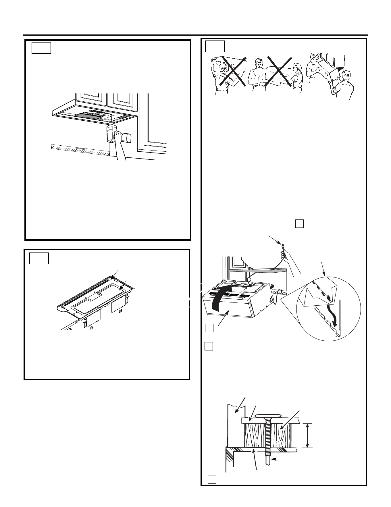
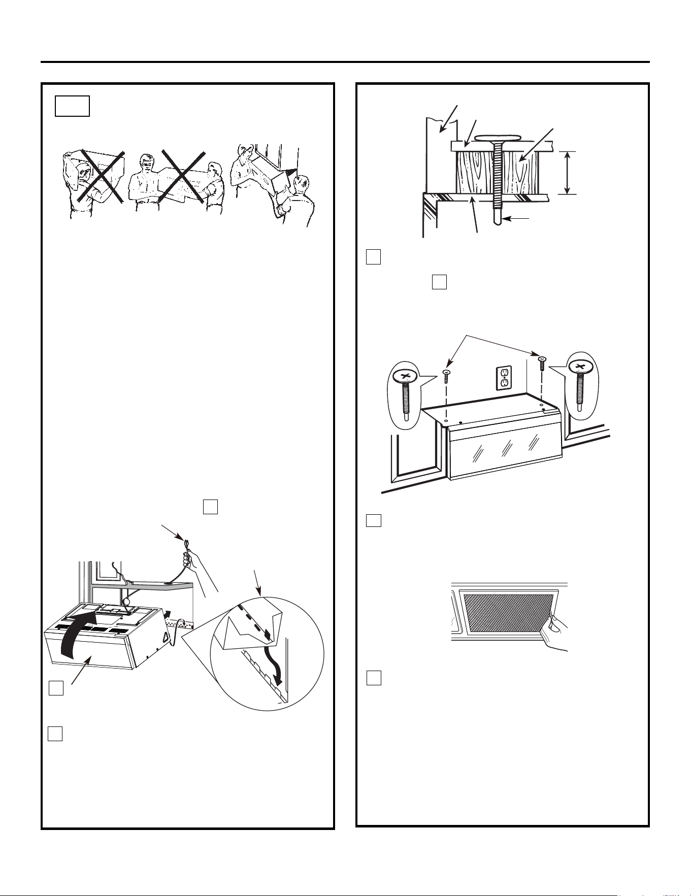
Attach the microwave oven to the top cabinet.
Cabinet Front
Cabinet Bottom Shelf
Filler Block
Microwave Oven Top
Equivalent to Depth
of Cabinet Recess
3
MOUNT THE MICROWAVE OVEN
FOR EASIER INSTALLATION AND PERSONAL
SAFETY, WE RECOMMEND THAT TWO PEOPLE
INSTALL THIS MICROWAVE OVEN.
NOTE: If your cabinet is metal, use the nylon
grommet around the power cord hole to prevent
cutting of the cord.
NOTE: We recommend using filler blocks if the
cabinet front hangs below the cabinet bottom shelf.
IMPORTANT: If filler blocks are not used,
case damage may occur from overtightening
screws.
Insert a self-aligning screw through top center
cabinet hole. Temporarily secure the oven by
turning the screw at least two full turns after the
threads have engaged. (It will be completely
tightened later.) Be sure to keep power cord
tight. Be careful not to pinch the cord, especially
when mounting flush to bottom of cabinet.
Self-Aligning Screw
4
NOTE: When mounting the
microwave oven, thread
power cord through hole in
bottom of top cabinet. Keep
it tight throughout Steps
CHECK BLOWER PLATE
• Place the microwave in its upright position, with the
top of the unit facing up.
• Check to see that the blower plate and cover plate
are correctly installed on the unit.
USE TOP CABINET TEMPLATE
FOR PREPARATION OF TOP
CABINET
• Read the instructions on the TOP CABINET
TEMPLATE.
• Tape it underneath the top cabinet.
• Drill the holes, following the instructions on the
TOP CABINET TEMPLATE.
CAUTION:Wear safety goggles when drilling holes
in the cabinet bottom.
You need to drill holes for the top support screws and
a hole large enough for the power cord to fit through.
Adjust top template accordingly if the microwave
is being spaced out from the wall due to cabinet depth
(including cabinet doors) of more th n 13"""''.
NOTE:
a
IMPORTANT: Do not grip or use the handle
or heat shield during installation. Do not
remove the cardboard spacers between the
heat shield and door.
A2.
A3.
A4.
EN-11
1–3. Do not pinch cord or
lift oven by pulling cord.
Lift microwave, tilt
it forward, and hook
slots at back bottom
edge onto four lower
tabs of mounting
plate.
1
2
Rotate front of oven
up against cabinet
bottom.
Blower Plate
Cover Plate
Installation Instructions
MOUNT THE MICROWAVE
OVEN (cont.)
7
6
Tighten the outer two screws to the top of the
microwave oven. (While tightening screws, hold
the microwave oven in place against the wall and
the top cabinet.)
packed with the microwave.
e ManualraC& esU eht eeS .sretlif esaerg llatsnI
INSTALLING OR CHANGE
THE CHARCOAL FILTER
(Some Models)
Unplug microwave oven or disconnect power.
NOTE: The charcoal filter is factory installed in some
models. Refer to the Use and Care to see if yours is
factory installed and for replacement information.
For models without the recirculation filter access
Remove the two vent plate screws
eht fo pot
no detacol
screwdriver.
Change the charcoal filter from the vnet
plate.
Replace the vent plate, reinstall the two vent plate
screws located on top of microwave using a #1
door,follow these steps to replace or install a charcoal
filter.
A4.
A5.
A 5.1
A 5.2
A 5.3
A 5.4
EN-12
5
Insert 2 self-aligning screws
through outer top cabinet
holes. Turn two full turns on
each screw.
microwave using a #1 Phillips
Charcoal
Filter
Vent Plate
Phillips screwdriver.
Close the microwave door. Plug in microwave
oven or reconnect power.
A 5.5
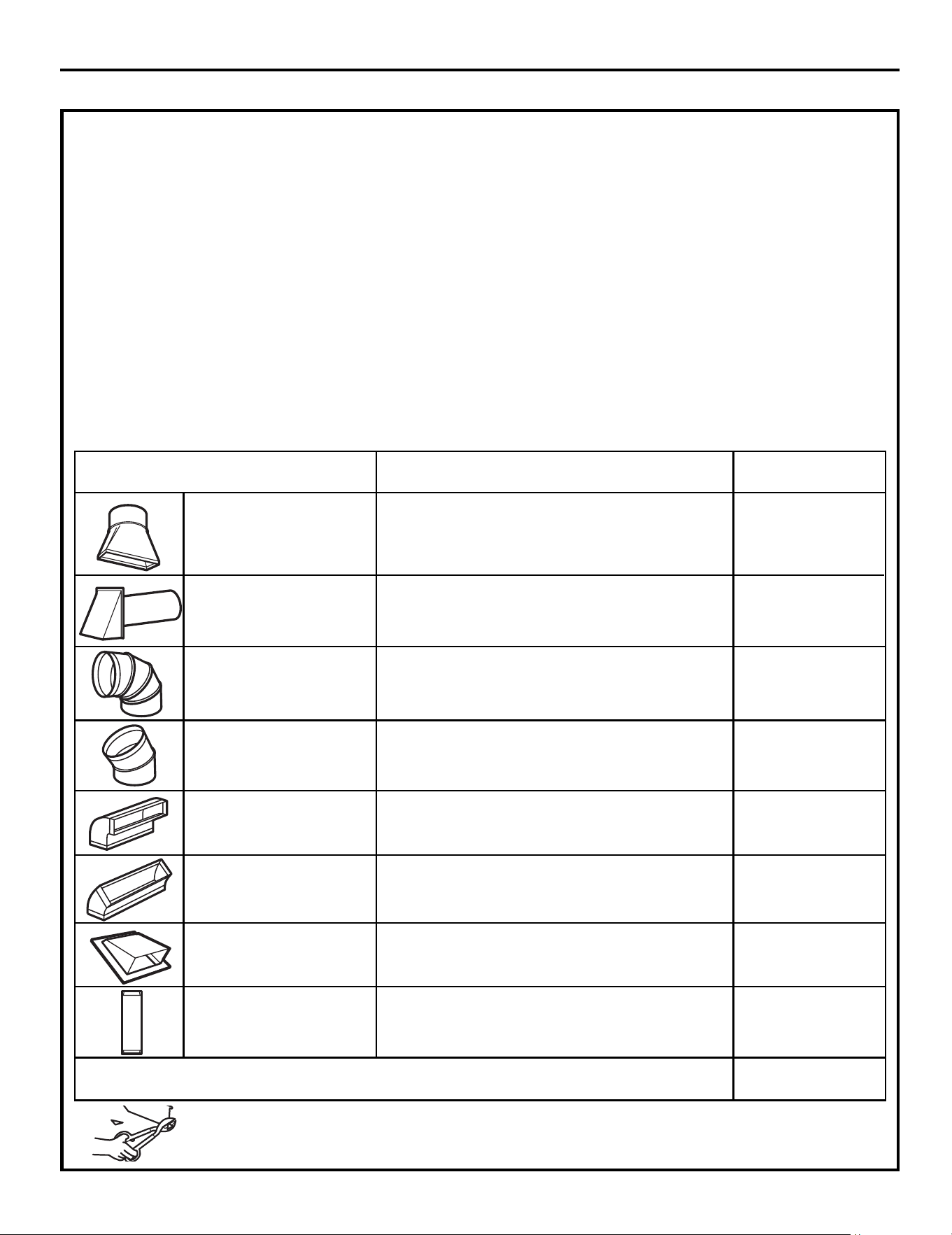
EQUIVALENT NUMBER EQUIVALENT
HTGNEL=DESUx HTGNELSECEIP TCUD
Rectangular-to-Round 5 Ft. (1.5 m) x ( ) = Ft. or m
Transition Adaptor*
m ro .tF=) (x)m 2.21( .tF 04paC llaW
m ro .tF=) (x)m 3( .tF 01woblE°09
m ro .tF=) (x)m 5.1( .tF 5woblE°54
m ro .tF=) (x)m 6.7( .tF 52woblE°09
m ro .tF=) (x)m 5.1( .tF 5woblE°54
m ro .tF=) (x)m 3.7( .tF 42paC fooR
Straight Duct 6“ (15.2 cm) 1 Ft. (0.3 m) x ( ) = Ft. or m
Round or 3
1
⁄4“ x 10“
(8.2 x 25.4 cm Rectangular)
Total Ductwork = Ft. or m
Equivalent lengths of duct pieces are based on actual tests
and reflect requirements for good venting performance with
any vent hood.
* IMPORTANT: If a rectangular-to-round transition
adaptor is used, the bottom corners of the damper
will have to be cut to fit, using the tin snips, in order
to allow free movement of the damper
.
NOTE: If you need to install ducts, note that the total
duct length of 3
1
⁄4” x 10” (8.2 x 25.4 cm) rectangular or
” (15.2 cm) diameter round duct
Outside ventilation requires an EXTERNAL EXHAUST
NOTE: It is important that venting be installed using
the most direct route and with as few elbows as possible.
This ensures clear venting of exhaust and helps prevent
blockages. Also, make sure dampers swing freely and
nothing is blocking the ducts.
Exhaust connection:
The exhaust adaptor has been designed to mate with
a standard 3
1
⁄4” x 10” (8.2 x 25.4 cm) rectangular duct.
If a round duct is required, a rectangular-to-round
Maximum duct length:
For satisfactory air movement, the total duct length of
3
1
⁄4” x 10” (8.2 x 25.4 cm) rectangular or
6 ”(15.2 cm)
diameter round duct should not
exceed 140 equivalent
feet (42.7 m).
Elbows, transitions, wall and roof caps,
etc.,
present additional resistance to airflow and are
equivalent to a section of straight duct which is longer
than their actual physical size. When calculating the total
duct length, add the equivalent lengths of all transitions
and adaptors plus the length of all straight duct sections.
The chart below shows you how to calculate total
equivalent ductwork length using the approximate feet
of equivalent length of some typical ducts.
Installation Instructions
INSTALLATION INSTRUCTIONS FOR EXTERNAL EXHAUST DUCTING
DUCT.Read the following carefully.
(12.5”
should not exceed 140 equivalent feet (42.7 m).
diameter/ 6
(12.5”
diameter/
7 cm)
7 cm)
transition adaptor must be used.
diameter duct is acceptable to use.
"
A 5"""''''' " (12.7cm)/ 6" (15.2cm)
"
EN-13
EQUIVALENT NUMBER EQUIVALENT
HTGNEL=DESUx HTGNELSECEIP TCUD
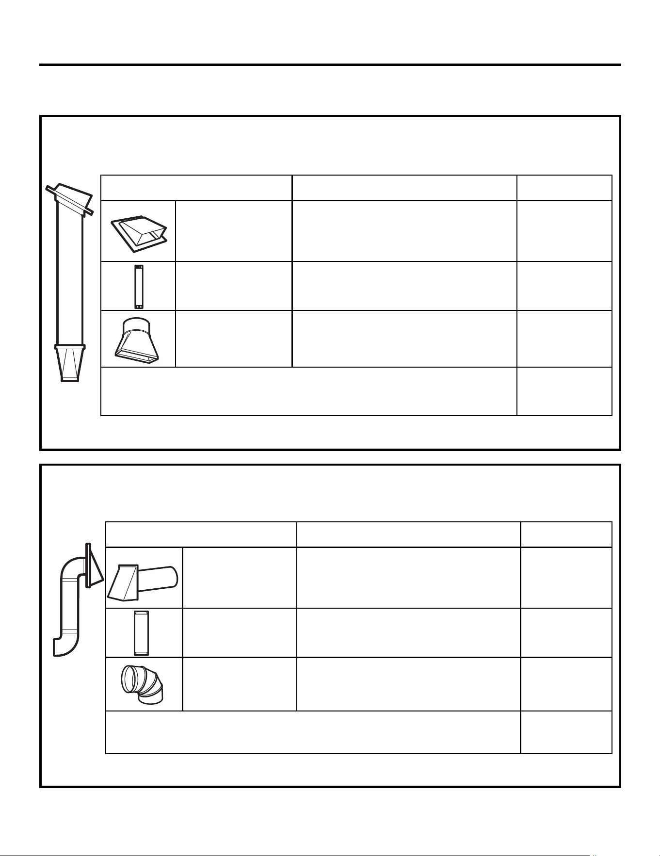
Roof Cap 24 Ft. (7.3 m) x (1) = 24 Ft. (7.3 m)
12 Ft. (3.6 m) Straight Duct 12 Ft. (3.6 m) x (1) = 12 Ft. (3.6 m)
(6”/15.2 cm Round)
Rectangular-to-Round 5 Ft. (1.5 m) x (1) = 5 Ft. (1.5 m)
Transition Adaptor*
Equivalent lengths of duct pieces are based on actual tests and
reflect requirements for good venting performance with any vent hood.
Total Length = 41 Ft. (12.5 m)
The following chart describes an example of one possible
ductwork installation.
OUTSIDE TOP EXHAUST (EXAMPLE ONLY)
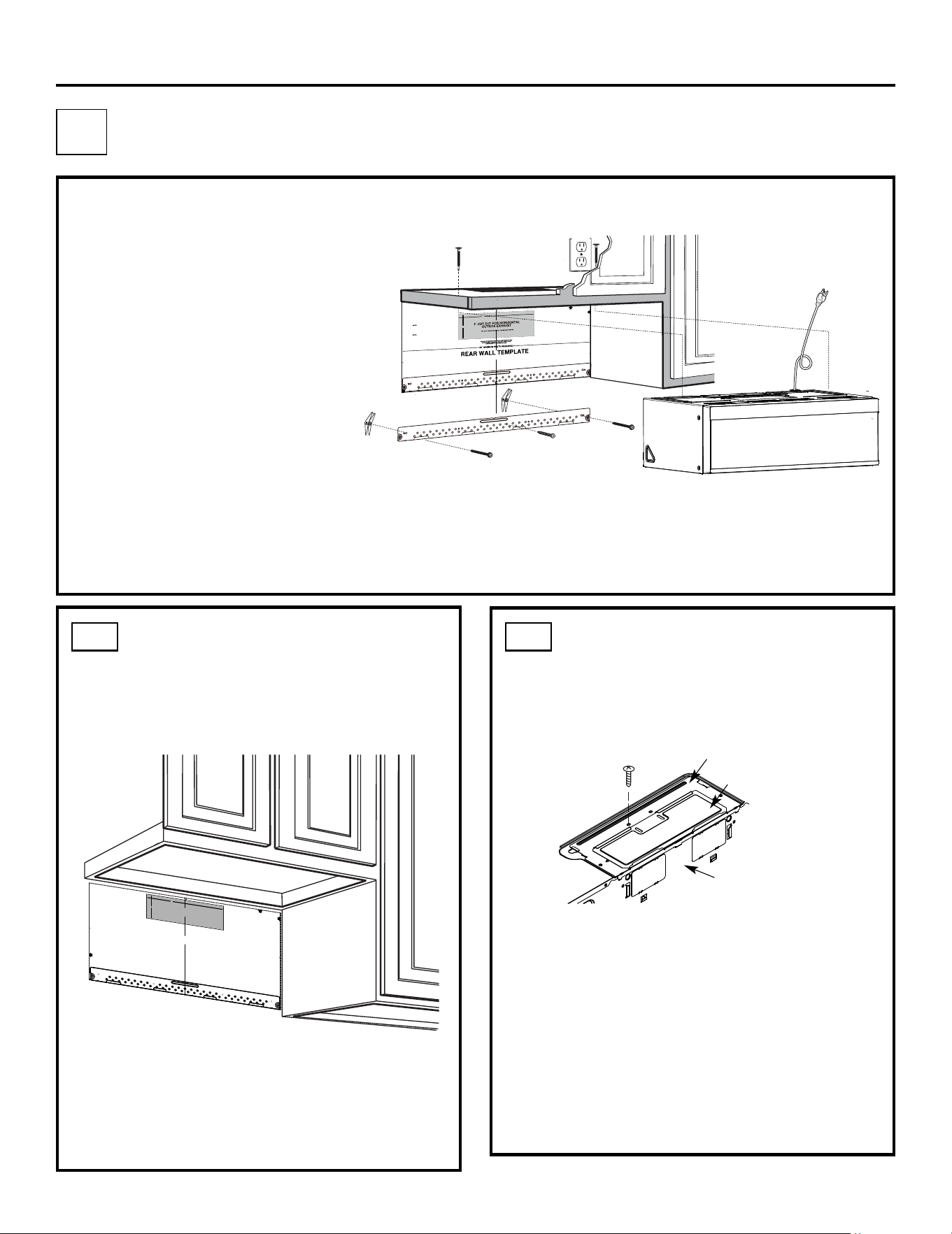
NOTE: For back exhaust, care should be taken to align exhaust with space between studs, or wall should be prepared
at the time it is constructed by leaving enough space between the wall studs to accommodate exhaust.
* IMPORTANT: If a rectangular-to-round transition adaptor is used, the bottom corners of the damper
will have to be cut to fit, using the tin snips, in order to allow free movement of the damper.
The following chart describes an example of one possible
ductwork installation.
Installation Instructions
OUTSIDE BACK EXHAUST (EXAMPLE ONLY)
EQUIVALENT NUMBER EQUIVALENT
HTGNEL=DESUx *HTGNELSECEIP TCUD
Wall Cap 40 Ft. (12.2 m) x (1) = 40 Ft. (12.2 m)
3 Ft. Straight Duct 3 Ft. (0.9 m) x (1) = 3 Ft. (0.9 m)
(3
1
⁄4” x 10”/8.2 x 25.4 cm
Rectangular)
90° Elbow 10 Ft. (3 m) x (2) = 20 Ft. (3 m)
Equivalent lengths of duct pieces are based on actual tests and
reflect requirements for good venting performance with any vent hood.
Total Length = 63 Ft. (19.2 m)
EXTERNAL EXHAUST DUCTING
EN-14
INSTALLATION OVERVIEW
B1. Prepare Rear Wall
B3. Attach Mounting Plate to Wall
B4. Prepare Top Cabinet
B5. Adjust Blower
B6. Mount the Microwave Oven
IMPORTANT NOTES:
• Make sure the screws for the
blower motor and blower plate
are securely tightened when
they are reinstalled. This will
help to prevent excessive
vibration.
•
been properly routed and secured,
and that the wires are not pinched.
Remove and save the screw that holds the blower
plate to the microwave. Lift off the blower plate.
Back of
Microwave
Installation Instructions
PREPARING THE REAR WALL
FOR OUTSIDE BACK EXHAUST
B1.
You need to cut an opening in the rear wall for
outside exhaust.
• Read the instructions on the REAR
WALL TEMPLATE.
• Tape it to the rear wall.
• Cut the opening, following the instructions of the
REAR WALL TEMPLATE.
B2.
OUTSIDE BACK EXHAUST (Horizontal Duct)
B
REMOVE BLOWER PLATE
B2. Remove Blower Plate
3
/8" T
O E
D
GE
NO
TE: IT IS VE
RY IM
POR
TAN
T
TO
READ
AND
FOLL
OW
TH
E
DIR
ECTIONS
IN THE INSTA
L
LATIO
N INS
TR
U
CTIO
NS
BEFORE
PR
OCEED
ING
WITH
TH
I
S
RE
AR
WALL
TEMPLATE
.
Th
is
Rear
W
all Te
m
pl
a
t
e s
erves
t
o
p
osit
i
on t
h
e bottom
m
ount
ing
pla
te
a
nd
t
o
lo
cat
e
the
h
ori
z
ontal exhaust
ou
t
let.
1.
Us
e
a
le
vel t
o check
t
hat
t
he
t
e
mpla
t
e
is
posi
t
ione
d
accurat
ely.
2. Locat
e
and
m
ark
at
lea
s
t
one
st
ud
on the
l
eft
or
right
side
o
f
the
ce
nterl
ine.
I
t
is im
port
ant
t
o use at leas
t
on
e wood
screw mount
e
d
firmly in
a
st
ud
t
o s
up
port
t
he
wei
ght
of th
e microw
ave.
M
a
rk
t
wo a
dditional
,
evenly
spa
ced
loca
tion
s
for
t
h
e
s
upplied
t
og
g
le
bolts.
3.
Dr
ill
h
oles
in
t
h
e
m
arked
l
oca
t
ion
s. Wh
ere
t
h
er
e
is
a st
ud,
dri
ll
a 3
/
16" ho
le
f
o
r wood
screws.
F
o
r
hol
es
t
hat
do
n
ot line
up with a stu
d,
drill
5
/
8
"
holes f
or
toggle
b
olt
s
.
DO
NOT
IN
STALL
THE
MO
UNTI
NG P
LAT
E
AT T
HI
S
T
I
M
E.
4.
Rem
ove
the
t
emplate from the
rear
wall.
5. Review t
h
e I
nstalla
t
io
n
I
n
s
truc
tion book
f
or your
installat
io
n
situ
at
io
n.
Lo
cate
and
mar
k hol
es to
alig
n with holes
in the
mo
u
nti
ng plate
.
IMP
O
RTA
NT:
LOCATE
AT LEAST ONE STU
D
O
N
EITH
ER
S
ID
E
O
F
TH
E
C
ENTER
LIN
E.
M
A
RK THE L
OC
AT
ION FOR
2 AD
D
IT
I
ONAL
,
EVENLY
SP
ACE
D TOGG
LE BOLTS IN
THE MOU
NTING
PLATE
AREA.
Lo
cate
and
mark hol
es to
a
lign with ho
les in the
mo
unting
p
late
.
IMPORTA
NT:
LO
CATE
AT LE
AST ON
E
STU
D O
N EIT
H
ER SIDE
OF
TH
E CE
N
TER
LINE.
MA
RK TH
E
L
OCAT
IO
N FOR
2 ADDIT
I
ONAL
, EVENLY
SPAC
ED
TOGG
LE
BO
LTS
IN
THE
M
OU
NTING PLA
TE
AR
EA.
Trim
the r
ea
r wa
ll te
mplate a
l
o
n
g the d
otted
line
.
Tri
m the
rea
r
wall
templa
te
a
l
o
ng the
d
otted lin
e.
12"
4"
Darle
vuelta
a
la
ho
ja
pa
r
a
consul
tar
la
ve
rsión
en
Español.
Make sure the motor wiring has
EN-15
3/8"TO
E
D
G
E
N
O
TE
:
IT IS V
E
RY
I
M
P
O
R
TA
NT T
O
RE
A
D AN
D
F
O
L
LO
WT
HE
D
IRE
CT
IO
N
S
I
N
T
HE
I
NS
TA
LLA
T
I
O
N INS
T
RUCT
ION
S
B
E
F
O
RE
P
R
O
CEE
DING
W
I
T
H
T
H
IS
RE
AR
W
ALL
T
E
MPLA
T
E
.
T
hi
s
R
e
ar
Wa
ll
Te
mpl
a
t
e
serves t
o
po
s
ition
th
e
b
otto
m
m
o
u
n
tin
g pl
ateand to l
ocate
t
h
e
h
oriz
o
n
ta
l
ex
hau
s
t
o
u
tl
e
t.
1.
Us
e a le
ve
l
to
ch
ec
k
t
h
a
t
t
h
e
t
emp
late
i
s p
o
s
iti
one
d
accuratel
y
.
2. L
oca
te a
ndm
ark at leas
t onestu
d
on theleft or
right side o
f
the c
e
nt
e
r
li
n
e
.
It is import
an
t t
o
use a
t
le
as
t o
ne
wood
s
cr
e
w
mou
nted fi
rmly in a
s
tud to suppor
t th
e weig
h
t
o
f
th
e micr
ow
ave
.
Mark two additional, evenlyspaced
l
o
catio
n
s f
or th
e
s
u
pplied t
oggle
b
o
lts.
3. Dr
i
ll
h
ole
s
i
n
th
e
m
arke
d
loca
t
ions.Whe
r
e
there
i
s
a s
t
ud, d
r
ill
a
3
/
1
6
"
h
ole f
or
wood scr
e
ws
. Fo
r
ho
le
s
thatd
o
not
line upw
ith
a s
tu
d,
d
r
il
l 5
/8"
h
o
les f
o
r
t
o
gg
l
e
bo
lts
.
DO NOT INSTAL
L T
HE
MOUN
T
ING PLATE
AT
T
HI
S
T
IM
E
.
4
.
R
emove th
e
te
m
plate
fro
mthe re
a
r
wall.
5.R
e
v
i
e
h
t
w
e
In
sta
ll
a
tion
I
nst
r
u
c
tio
n book
f
or
y
o
u
r
in
s
tallation
s
i
tu
at
i
on
.
Locate and m
a
rk
holes to
a
l
i
gn
w
ith hole
s
i
n t
h
e
mo
un
ti
ng
pl
a
te.
IM
P
ORTA
NT
:
LO
C
AT
E
A
T
L
EA
S
T
ON
E
S
TUD
ON EI
T
H
ER
S
ID
E O
F
T
H
E
CENT
E
RLIN
E
.
M
AR
K
T
HE L
O
CATI
ONFO
R
2 ADD
ITIO
N
AL, EVEN
L
Y
S
P
A
CE
D
T
OGGLE BO
L
T
S
I
N
T
HE
MO
U
NTING
PL
A
TE
A
R
EA
.
Locate
a
nd m
a
r
k
h
o
le
s
to alig
n
wit
h
ho
l
es
i
n t
h
e
.
e
t
a
l
p
g
nitn
u
o
m
I
M
P
OR
T
A
N
T
:
LO
CA
T
E
AT
LEAST O
N
E
ST
UD ON EI
THE
R
SID
E
OF
T
H
E
C
ENTE
R
LI
N
E.
M
A
RK
T
HE
LOCAT
IO
NFO
R
2 A
DDITIO
N
A
L
, EV
E
N
LY
S
PAC
E
D
TO
G
GLE
B
O
LTS IN
T
H
E MOUNTING P
LATE
AR
EA.
T
rim
t
he
r
ear wal
l t
empl
a
te
a
longth
e do
tt
e
d li
n
e
.
Trim th
e
r
ea
r wal
l
t
e
mp
la
t
e
a
long
the
do
tted
li
n
e
.
12"
4"
D
arl
e
vu
elta
a
l
ahoja para
con
s
ultarla
v
e
r
s
i
ó
n
e
n
E
sp
año
l.
Blower Plate
Cover Plate
• The cover plate is installed with the blower plate,
not need to unintall.
ATTACH THE MOUNTING
PLATE TO THE WALL
B3.
•
Read the instructions on the TOP CABINET
TEMPLATE.
• Tape it underneath the top cabinet.
• Drill the holes, following the instructions on the
TOP CABINET TEMPLATE.
CAUTION:Wear safety goggles when drilling holes
in the cabinet bottom.
Wall
Mounting
Plate
Spacing for Toggles More
Than Wall Thickness
Toggle
Bolt
Toggle Wings
To use toggle bolts:
Bolt End
Installation Instructions
Attach the plate to the wall using toggle bolts.
At least one wood screw must be used to attach
the plate to a wall stud.
Remove the toggle wings from the bolts.
Insert the bolts into the mounting plate through
the holes designated to go into drywall and reattach
the toggle wings to
3
⁄4″(19 mm) onto each bolt.
1
2
Place the mounting plate against the wall and
insert the toggle wings into the holes in the wall
to mount the plate.
NOTE: Before tightening toggle bolts and wood
screw, make sure the bottom of the mounting plate
touch the bottom of the cabinet when pushed flush
against the wall and that the plate is properly
centered under the cabinet.
CAUTION:Be careful to avoid pinching fingers
between the back of the mounting plate and the wall.
Tighten all bolts. Pull the plate away from the wall
to help tighten the bolts.
3
4
2
1
ADAPTING MICROWAVE
AIR DIRECTOR FOR OUTSIDE
BACK EXHAUST
B5.
Forward
Openings Facing
Carefully pull out the air director.
Before:
USE TOP CABINET TEMPLATE
FOR PREPARATION OF TOP
CABINET
B4.
You need to drill holes for the top support screws and
a hole large enough for the power cord to fit through.
3
EN-16
Air Director
Rotate the air director counterclockwise 180°
Before Rotation After Rotation
Back of mircrowave
Knockout Plates:
Snip all 4 webs on
each knockout panel
and remove the metal
knockouts for rear airflow.
Please take care to
remove any sharp edges
created from removing
the knockout plates.
with snips. (For some models)
Remove the knockout plates in the back of the unit
ADAPTING MICROWAVE
BLOWER FOR OUTSIDE
BACK EXHAUST (cont.)
B5.
Installation Instructions
4
5
6
EN-17
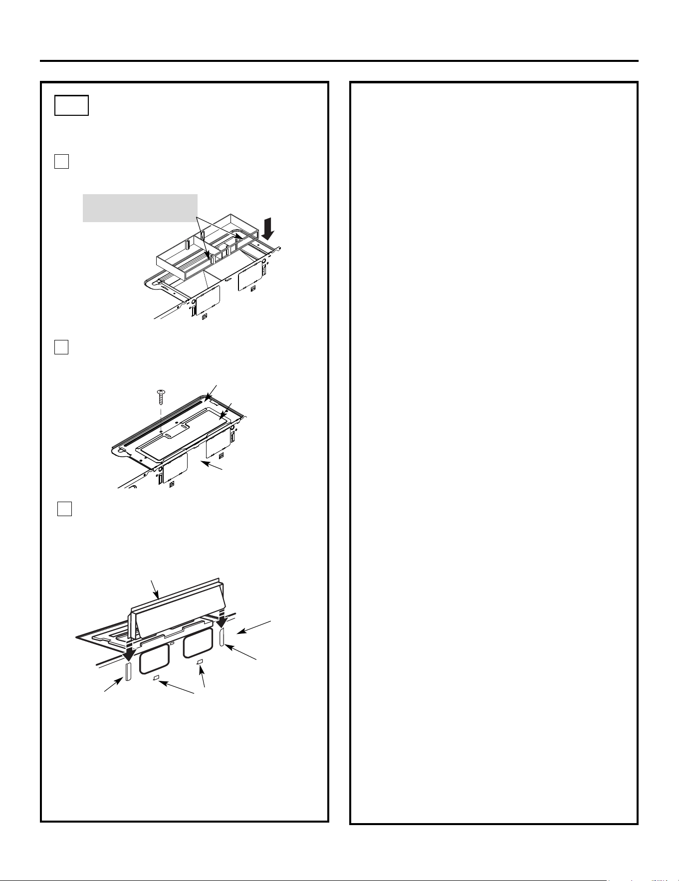
Place the air director back into the opening.
AFTER: Air Director
Openings Facing Back
Secure the blower plate to the microwave with
the original screw.
Attach the exhaust adaptor to the rear of the
oven by sliding it into the guides at the top
center of the back of the oven.
Push in securely until it is in the lower locking
tabs. Take care to assure that the damper hinge
is installed so that it is at the top and that the
damper swings freely.
Guide
Guide
Adaptor
Locking Tabs
Back of
Microwave
Back of
Microwave
Blower Plate
Cover Plate
Attach the microwave oven to the top cabinet.
Installation Instructions
3
MOUNT THE MICROWAVE
OVEN
B6.
FOR EASIER INSTALLATION AND PERSONAL
SAFETY, WE RECOMMEND THAT TWO PEOPLE
INSTALL THIS MICROWAVE OVEN.
NOTE: If your cabinet is metal, use the nylon
grommet around the power cord hole to prevent
cutting of the cord.
NOTE: We recommend using filler blocks if the
cabinet front hangs below the cabinet bottom shelf.
IMPORTANT: If filler blocks are not
used, case damage may occur from
overtightening screws.
Insert a self-aligning screw through top center
cabinet hole. Temporarily secure the oven by
turning the screw at least two full turns after the
threads have engaged. (It will be completely
tightened later.) Be sure to keep power cord
tight. Be careful not to pinch the cord, especially
when mounting flush to bottom of cabinet.
7
6
5
Cabinet Front
Cabinet Bottom Shelf
Tighten the outer two screws to the top of the
microwave oven. (While tightening screws, hold
the microwave oven in place against the wall and
the top cabinet.)
Filler Block
Microwave Oven Top
Equivalent
to Depth
of Cabinet
Recess
Insert 2 self-aligning screws
through outer top cabinet
holes. Turn two full turns on
each screw.
packed with the microwave.
Self-Aligning Screw
4
NOTE: When mounting the
microwave oven, thread
power cord through hole in
bottom of top cabinet. Keep
it tight throughout Steps
1–3. Do not pinch cord or
lift oven by pulling cord.
Lift microwave, tilt it
forward, and hook
slots at back bottom
edge onto four lower
tabs of mounting
plate.
1
e manualraC & esU eht eeS .sretlif esaerg llatsnI
IMPORTANT: Remove the cardhoard spacers between
heat shield and door.
IMPORTANT: Do not grip or use the handle
or heat shield during installation. Do not
remove the cardboard spacers between the
heat shield and door.
EN-18
2
Rotate front of oven
up against cabinet
bottom.
Place the mounting plate against the wall and
insert the toggle wings into the holes in the wall
to mount the plate.
NOTE: Before tightening toggle bolts and wood
screw, make sure the bottom of the mounting plate
touch the bottom of the cabinet when pushed
flush against the wall and that the plate is properly
centered under the cabinet.
CAUTION:Be careful to avoid pinching fingers
between the back of the mounting plate and the wall.
Tighten all bolts. Pull the plate away from the wall
to help tighten the bolts.
3
4
ATTACH THE MOUNTING
PLATE TO THE WALL
Attach the plate to the wall using toggle bolts.
At least one wood screw must be used to attach
the plate to a wall stud.
Remove the toggle wings from the bolts.
Insert the bolts into the mounting plate
through the holes designated to go into drywall
and reattach the toggle wings to
3
⁄4″(19 mm) onto
each bolt.
1
INSTALLATION OVERVIEW
Attach Mounting Plate to Wall
Prepare Top Cabinet
Mount Microwave Oven
Adjust Exhaust Adaptor
Wall
Mounting
Plate
Spacing for Toggles
More Than Wall
Thickness
Bolt End
Toggle
Bolt
Toggle Wings
To use toggle bolts:
Installation Instructions
2
OUTSIDE TOP EXHAUST (Vertical Duct)
IMPORTANT NOTES:
• Make sure the screws for the
blower motor and blower plate
are securely tightened when
they are reinstalled. This will
help to prevent excessive
vibration.
• Make sure the motor wiring has
been properly routed and secured,
and that the wires are not pinched.
. Connect Ductwork
Check Damper Operation
Adapting Microwave Blower for
Outside Top Exhaust
C
C2.
C1.
C3.
C4.
C6.
C5.
C7
C1.
EN-19
3/8
"
TO
E
D
G
E
N
O
TE
:
IT
IS V
E
RY
I
M
POR
TA
N
T
T
O
RE
A
D AN
D
F
O
L
LO
WT
HE
D
IRE
CT
ION
S
I
N THE I
N
S
T
A
LLA
T
ION INST
RU
C
T
I
ONS
B
E
F
O
RE
P
R
O
CE
EDING
W
I
T
H
T
H
IS
REA
R
W
ALL
T
E
MPLA
TE
.
T
hi
s
R
e
ar
Wa
ll
Te
mpl
a
t
e
se
rve
s t
o
p
o
s
ition
th
e
b
otto
m
m
o
u
n
tin
g pl
ateand to l
ocate
t
h
e
h
oriz
o
n
ta
l
e
x
hau
st
o
u
tl
e
t
.
1.
Us
e a le
ve
l
to
c
h
ec
k
t
h
a
t
t
h
e
t
emp
late
i
s p
o
s
iti
one
d
accuratel
y
.
2. L
oca
te
a
ndm
ark a
t
leas
t onestu
d
on theleft or
r
i
ght sid
e
o
f
th
e
c
e
nt
e
rli
n
e
.
I
t is import
an
t t
o
use
a
t
le
as
t o
ne
wo
o
d
s
cr
e
w
mou
nted fi
rmly in a
s
tud to suppor
t th
e weigh
t
o
f
th
e micr
ow
ave
.
Mark two a
d
d
i
tional, evenlyspaced
l
o
catio
n
s
f
or
th
e
s
u
pplied t
o
g
gle b
o
lts.
3. Dr
i
ll
h
ol
es
i
n
th
e
m
ark
e
d
l
oca
t
i
ons.W
he
r
e
there
i
s
a stud, d
r
ill
a
3
/
1
6
"
h
ole for
w
ood scr
e
ws
. F
o
r ho
le
s
that
d
o
not
line upw
ith
a
s
tu
d,
dr
il
l 5
/8"
ho
l
e
s fo
r
t
o
gg
le
bo
lts
.
DO
N
OT INSTAL
L T
HE
MOUN
T
ING PLATE
AT
T
HI
S
T
IM
E
.
4
.
R
emove
th
e
te
m
pl
a
te
fro
mth
e
r
e
a
r w
al
l.
5
.
R
e
v
i
e
h
t
w
e
I
n
sta
ll
a
t
ion
I
n
st
r
u
c
tio
n bo
o
k f
or
y
ou
r
in
s
t
a
llatio
n
s
i
tu
at
i
on
.
Locate and m
a
r
k holes to
a
l
i
gn
w
ith hole
s
i
n th
e
m
o
un
ti
ng
pl
a
te
.
I
M
PO
RT
ANT
:
LO
CAT
E
A
T L
EA
ST
ONE S
TUD
ON EI
T
H
ER
S
ID
E O
F
T
HE C
ENT
E
RLINE.
M
AR
K
T
HE
LOCATIO
NFO
R 2
ADD
ITIO
N
AL, EVEN
L
Y
S
P
A
CE
D
T
OGGLE BO
LTS
I
N THE
MO
U
NTING
PL
A
T
E
A
R
EA
.
Locate
a
nd m
a
r
k
h
o
le
s
to alig
n
w
it
h
h
o
l
es
i
n t
h
e
.
e
t
a
l
p
g
ni
tn
u
o
m
IMPO
R
T
ANT:
L
O
CA
T
E
AT
LEA
S
T O
N
ESTUD ON EI
THE
R
SID
E
OF
T
H
E
C
ENTE
R
L
I
N
E.
M
A
RK
T
HE LOCAT
IO
NF
O
R 2 A
DDITIO
N
A
L
, E
V
E
N
LY
SPACE
DTOGGL
E
BOLTS IN TH
E M
OUNTING
P
LATE
AR
EA.
T
rim
t
he
re
ar w
a
l
l t
empl
a
te
a
longth
e do
tt
e
d
l
i
n
e
.
Trim th
e rea
r w
al
l
t
e
mpl
a
t
e
a
long
the
do
t
ted lin
e.
12"
4"
Darl
e
v
u
eltaa la
hojapa
ra
con
sultarla
v
e
r
s
i
ó
n
e
n
Esp
añol
.
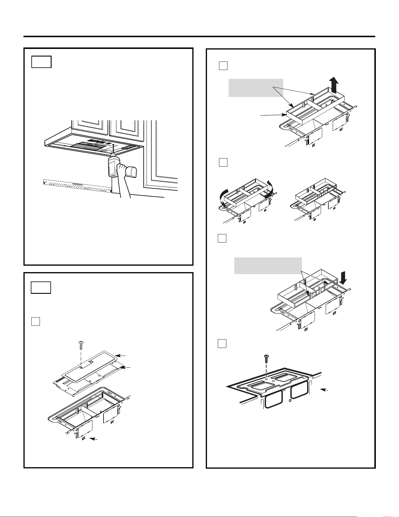
USE TOP CABINET TEMPLATE
FOR PREPARATION OF TOP
CABINET
You need to drill holes for the top support screws, a
hole large enough for the power cord to fit through,
and a cutout large enough for the exhaust adaptor.
• Read the instructions on the TOP CABINET
TEMPLATE.
• Tape it underneath the top cabinet.
• Drill the holes, following the instructions on the
TOP CABINET TEMPLATE.
CAUTION:Wear safety goggles when drilling holes
in the cabinet bottom.
Installation Instructions
Remove the screw that holds the blower plate
to the microwave. Remove the cover plate.
2
1
ADAPTING MICROWAVE
AIR DIRECTOR FOR OUTSIDE
TOP EXHAUST
3
C2.
C3.
EN-20
Back of
Microwave
Blower Plate
Cover Plate
Forward
Openings Facing
Carefully pull out the air director.
Before:
Air Director
Rotate the air director counterclockwise 180°
Before Rotation After Rotation
4
Place the air director back into the opening.
AFTER: Air Director
Openings Facing Back
Replace blower plate with the screw removed in
Step 1. Make sure the screw is tight.
Back of
Microwave
5
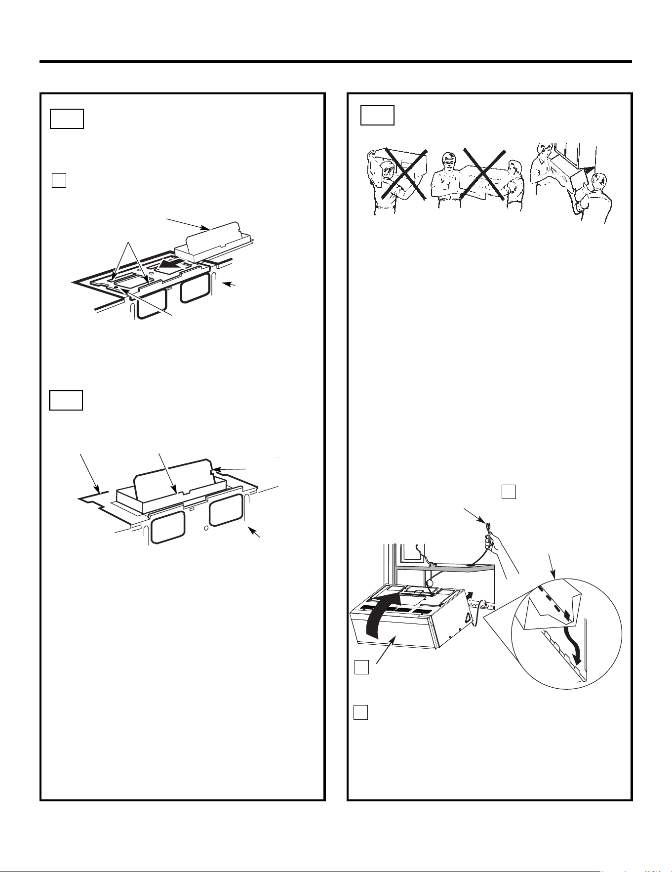
3
MOUNT THE MICROWAVE
OVEN
FOR EASIER INSTALLATION AND PERSONAL
SAFETY, WE RECOMMEND THAT TWO PEOPLE
INSTALL THIS MICROWAVE OVEN.
NOTE: If your cabinet is metal, use the nylon
grommet around the power cord hole to prevent
cutting of the cord.
NOTE: We recommend using filler blocks if the
cabinet front hangs below the cabinet bottom shelf.
IMPORTANT: If filler blocks are
not used, case damage may occur from
overtightening screws.
Insert a self-aligning screw through top center
cabinet hole. Temporarily secure the oven by
turning the screw at least two full turns after the
threads have engaged. (It will be completely
tightened later.) Be sure to keep power cord
tight. Be careful not to pinch the cord, especially
when mounting flush to bottom of cabinet.
NOTE: When mounting the
microwave oven, thread
power cord through hole in
bottom of top cabinet. Keep
it tight throughout Steps
1–3. Do not pinch cord or
lift oven by pulling cord.
Lift microwave, tilt it
forward, and hook
slots at back bottom
edge onto four lower
tabs of mounting
plate.
1
CHECK FOR PROPER
DAMPER OPERATION
Exhaust Adaptor
Blower Plate
Damper
Back of
Microwave
• Make sure tape securing damper is removed and
damper pivots easily before mounting microwave.
• You will need to make adjustments to assure proper
alignment with your house exhaust duct after the
microwave is installed.
ADAPTING MICROWAVE
BLOWER FOR OUTSIDE
TOP EXHAUST
6
Back of
Microwave
Guide
Adaptor
Locking Tab
damper swings freely.
Attach the exhaust adaptor to the top of the
blower plate by sliding it into the guides
of the
blower plate.
Push in securely until it is in the locking
tabs.
Take care to assure that the damper hinge
is
installed so that the
.
.
Installation Instructions
IMPORTANT: Do not grip or use the handle
or heat shield during installation. Do not
remove the cardboard spacers between the
heat shield and door.
C3.
C4
C5
(cont.)
EN-21
2
Rotate front of oven
up against cabinet
bottom.
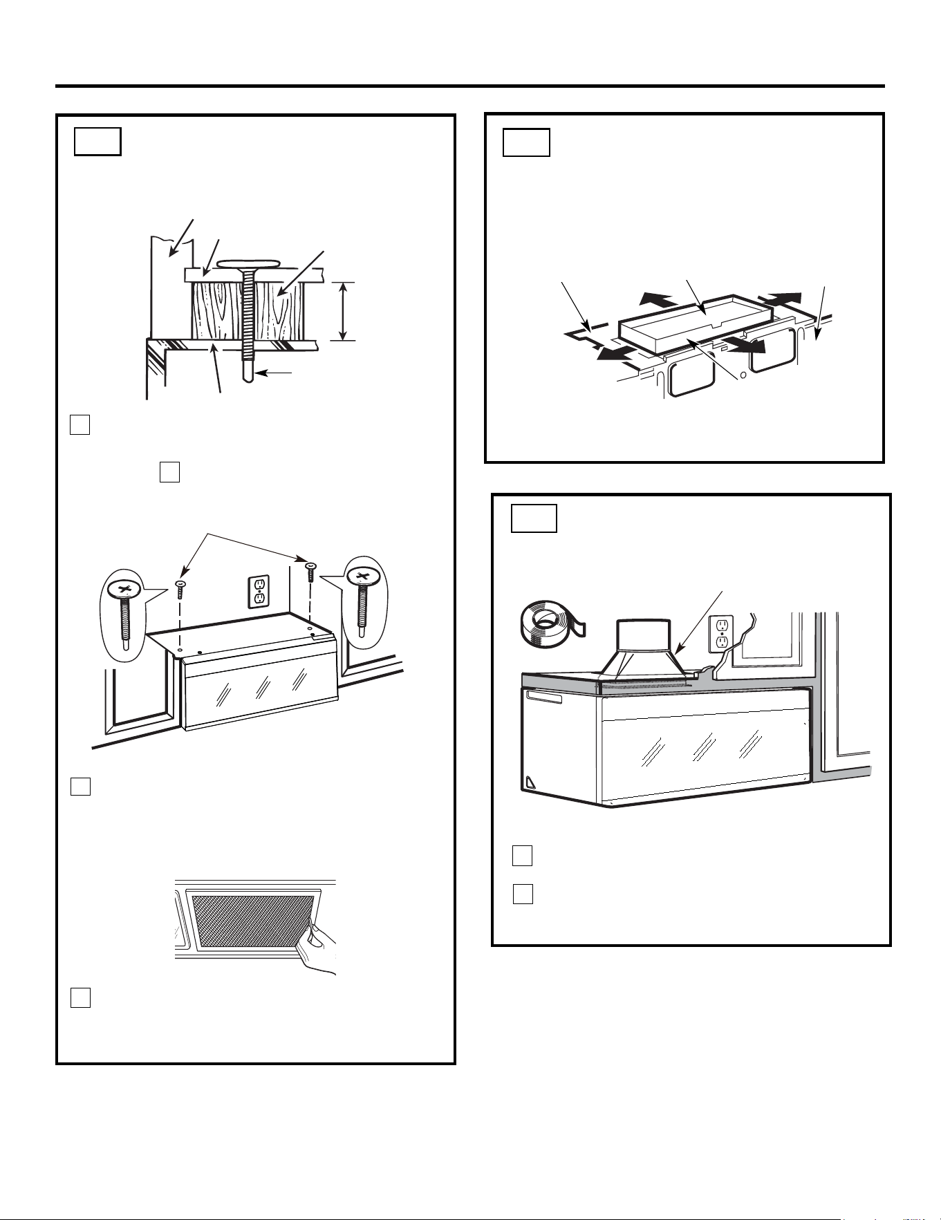
4
Attach the microwave oven to the top cabinet.
8
7
Cabinet Front
Cabinet Bottom Shelf
Tighten the outer two screws to the top of the
microwave oven. (While tightening screws, hold
the microwave oven in place against the wall and
the top cabinet.)
Filler Block
Microwave Oven Top
Equivalent
to Depth
of Cabinet
Recess
Insert 2 self-aligning screws
through outer top cabinet
holes. Turn two full turns on
each screw.
Install grease filters. See the Use Care
packed with the microwave.
Installation Instructions
ADJUST THE EXHAUST
ADAPTOR
Open the top cabinet and adjust the exhaust adaptor
to connect to the house duct.
Back of
Microwave
For Front-to-Back or
Side-to-Side Adjustment,
Slide the Exhaust Adaptor
as Needed
Blower Plate
Damper
Self-Aligning Screw
5
MOUNT THE MICROWAVE
OVEN (cont.)
CONNECTING DUCTWORK
1
2
Extend the house duct down to connect to
the exhaust adaptor.
furnance
Seal exhaust duct joints using duct tape
for high temperature applications.
C5.
C6.
C7.
EN-22
& and
House Duct
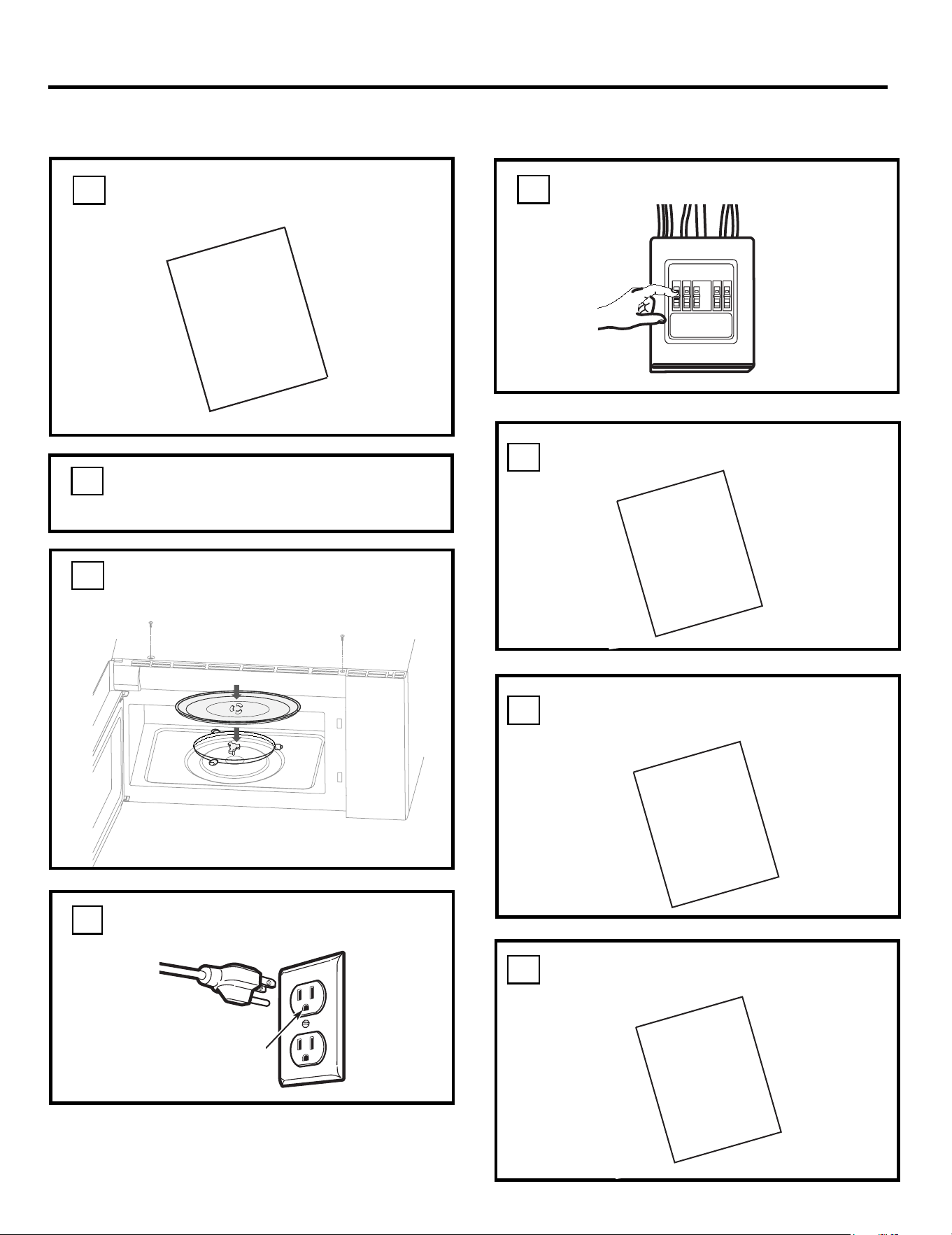
Remove all packing material from the
microwave oven.
2.
Make sure the microwave oven has been
installed according to instructions.
1.
BEFORE YOU USE YOUR MICROWAVE
Ensure proper
ground exists
before use
INSTALLATION
INSTRUCTIONS
3.
Installation Instructions
.ytivac ni yarts salgdn a gnir
Install turntable
4.
KEEP INSTALLATION INSTRUCTIONS
FOR THE LOCAL INSPECTOR’S
USE.
7.
6.
INSTALLATION
INSTRUCTIONS
MANUAL
USE
CARE
&
PRODUCT
CARD
Read the Manual.
&
REGISTRATION
USE CARE
Replace house fuse or turn breaker back on.
5.
FILL OUT PRODUCT REGISTRATION CARD
.
8
AN SEND IN.
Plug power cord into a seperate and dedicated
15- to 20-amp electrical outlet.
EN-23
