MODEL:
EX38DT
(RHFE-1006FTA)
RHF1006-1750(02)
Direct Vent Wall Furnace
Installation and Operation Manual
2 EX38DT Installation and Operation Manual
—Iftheinformaonintheseinstruconsisnotfollowedexactly,afireorexplosion
mayresultcausingpropertydamage,personalinjuryordeath.
— Donotstoreorusegasolineorotherflammablevaporsandliquidsinthevicinityof
thisoranyotherappliance.
— WHATTODOIFYOUSMELLGAS
Donottrytolightanyappliance.
Donottouchanyelectricalswitch;donotuseanyphoneinyourbuilding.
Immediatelycallyourgassupplierfromaneighbor’sphone.Followthegas
supplier’sinstrucons.
Ifyoucannotreachyourgassupplier,callthefiredepartment.
— Installaonandservicemustbeperformedbyalicensedprofessional.
WARNING
Copyright 2022 Rinnai America Corporation. Rinnai® is a registered trademark of Rinnai
Corporation used under license by Rinnai America Corporation. Rinnai America Corporation
continually updates materials, and as such, content is subject to change without notice.
This appliance may be installed in an aermarket, permanently located, manufactured
home (USA only) or mobile home, where not prohibited by local codes.
This appliance is only for use with the type of gas indicated on the rang plate. This
appliance is not converble for use with other gases, unless a cerfied kit is used.

EX38DT Installation and Operation Manual 3
Contents
1. Welcome ...................................................................................................................................... 4
1.1 To The Installer .................................................................................................................. 4
1.2 To The Consumer .............................................................................................................. 4
1.3 Acronyms and Abbreviations ............................................................................................. 4
2. Safety ........................................................................................................................................... 5
2.1 Safety Symbols .................................................................................................................. 5
2.2 Safety Precautions ............................................................................................................. 5
3. About the Direct Vent Furnace .................................................................................................. 7
3.1 Main Components ............................................................................................................. 7
3.2 Specifications .................................................................................................................... 8
3.3 Dimensions ....................................................................................................................... 9
4. Installation ................................................................................................................................. 10
4.1 Installation Guidelines ..................................................................................................... 10
4.2 What You Will Need ........................................................................................................ 11
4.3 Choose an Installation Location ..................................................................................... 12
4.4 Installation Steps ............................................................................................................ 16
4.5 Post-Installation Checklist ................................................................................................ 28
5. Operation ................................................................................................................................... 29
5.1 Safety Precautions .......................................................................................................... 29
5.2 Operating Instructions ..................................................................................................... 30
5.3 Control Panel .................................................................................................................. 31
5.4 Basic Operation Settings ................................................................................................ 31
5.5 Add Water to the Humidifier ............................................................................................ 36
5.6 Adjust Air Flow Direction ................................................................................................. 36
5.7 Restart Function ............................................................................................................. 36
5.8 Diagnostic Codes ............................................................................................................ 37
6. Maintenance .............................................................................................................................. 38
7. Troubleshooting ............................................................................................................
........... 39
8. Parts ........................................................................................................................................... 41
9. Appendices ............................................................................................................................... 51
9.1 Massachusetts State Gas Regulations ........................................................................... 51
9.2 Wiring Diagram ............................................................................................................... 52
9.3 Ladder Diagram .............................................................................................................. 53
10. Warranty .................................................................................................................................. 54

4 EX38DT Installation and Operation Manual
1. Welcome
Thank you for purchasing a Rinnai Direct
Vent Furnace. Before installing and operating
the direct vent furnace, be sure to read these
instructions completely and carefully to
familiarize yourself with the direct vent
furnace's features and functionality.
You must read the entire manual to properly
operate the direct vent furnace.
Refer to section "6. Maintenance" to stay up
to date on regular maintenance for your
direct vent furnace.
As when using any appliance generating
heat, there are certain safety precautions
you should follow. See section “2. Safety”
for detailed safety precautions.
Be sure your direct vent furnace is installed
by a trained and qualified professional.
If installing in the state of Massachusetts,
you must read section “9.1 Massachusetts
State Gas Regulations” in this manual.
Keep this manual for future reference.
It is recommended that a trained and
qualified professional who has attended a
Rinnai training class complete the
installation. The warranty may be voided
due to any improper installation.
A trained and qualified professional
should have skills such as:
Gas sizing
Connecting gas lines, valves, and
electricity
Knowledge of applicable national,
state, and local codes
Installing venting through a wall
Training in installation of direct vent
furnaces. Training on Rinnai Direct
Vent Furnaces is accessible at
rinnaipro.myabsorb.com.
Read all instructions in this manual before
installing the direct vent furnace. The
direct vent furnace must be installed
according to the exact instructions in this
manual.
Proper installation is the responsibility of
the trained and qualified professional.
When installation is complete, leave this
manual with the direct vent furnace or
give the manual directly to the consumer.
1.1 To The Installer
1.2 To The Consumer
ANSI
American National Standards
Institute
BTU British Thermal Unit
LPG Liquid Propane Gas
NG Natural Gas
NPT National Pipe Thread
OEM Original Equipment Manufacturer
PSI Pounds per Square Inch
VAC Volts Alternating Current
wc Inches of Water Column
Table 1 below lists common acronyms and
abbreviations used in this manual:
Table 1. Acronyms and Abbreviations
1.3 Acronyms and
Abbreviations
EX38DT Installation and Operation Manual 5
2. Safety
2.1 Safety Symbols
Indicates an imminently hazardous
situation which, if not avoided, will result in
personal injury or death.
Indicates a potentially hazardous situation
which, if not avoided, could result in personal
injury or death.
Indicates a potentially hazardous situation
which, if not avoided, could result in minor
or moderate injury. It may also be used to
alert against unsafe practices.
Safety alert symbol. Alerts you to
potential hazards that can kill or
hurt you and others.
This manual contains the following important
safety symbols. Always read and obey all
safety messages.
DANGER
CAUTION
WARNING
Repairs should be performed by a
trained and qualified professional.
Keep the area around the furnace
clear and free from combustible
materials, gasoline, and other
flammable vapors and liquids.
Never store liquid propane containers
indoors.
Do not use this furnace if any part has
been under water. Immediately call a
trained and qualified professional to
inspect the furnace and to replace any
part of the control system and any gas
control which has been under water.
This furnace is equipped with a three-
prong plug for your protection against
shock hazard and should be plugged
directly into a properly grounded three-
prong receptacle. Do not cut or remove
the ground prong from this plug.
Any alteration to the furnace or its
controls can be dangerous.
Do not operate furnace with the panels
removed, cracked or broken.
Replacement of the panels should be
performed by a trained and qualified
professional.
WARNING
2.2 Safety Precautions
6 EX38DT Installation and Operation Manual
WARNING
When an existing Category I heater is removed or
replaced, the original venting system may no
longer be sized to properly vent the attached
appliances. Instructions shall also indicate effects
of an improperly sized venting system (formation of
condensate, leakage, spillage, etc.) and shall
specify the following test procedure.
WARNING: CARBON MONOXIDE POISONING
HAZARD
Failure to follow the steps outlined below for each
appliance connected to the venting system being
placed into operation could result in carbon
monoxide poisoning or death.
The following steps shall be followed for each
appliance connected to the venting system being
placed into operation, while all other appliances
connected to the venting system are not in
operation:
1. Seal any unused openings in the venting
system.
2. Inspect the venting system for proper size and
horizontal pitch, as required in the National
Fuel Gas Code, ANSI Z223.1/NFPA 54 or the
Natural Gas and Propane Installation Code,
CSA B149.1 and these instructions. Determine
that there is no blockage or restriction,
leakage, corrosion and other deficiencies
which could cause an unsafe condition.
3. As far as practical, close all building doors and
windows and all doors between the space in
which the appliance(s) connected to the
venting system are located and other spaces of
the building.
4. Close fireplace dampers.
5. Turn on clothes dryers and any appliance not
connected to the venting system. Turn on any
exhaust fans, such as range hoods and
bathroom exhausts, so they are operating at
maximum speed. Do not operate a summer
exhaust fan.
6. Follow the lighting instructions. Place the
appliance being inspected into operation.
Adjust the thermostat so appliance is operating
continuously.
7. Test for spillage from draft hood equipped
appliances at the draft hood relief opening after
5 minutes of main burner operation. Use the
flame of a match or candle.
8. If improper venting is observed during any of
the above tests, the venting system must be
corrected in accordance with the National Fuel
Gas Code, ANSI Z223.1/NFPA 54 and/or
Natural Gas and Propane Installation Code,
CSA B149.1.
9. After it has been determined that each
appliance connected to the venting system
properly vents when tested as outlined above,
return doors, windows, exhaust fans, fireplace
dampers and any other gas-fired burning
appliance to their previous conditions of use.
Do not block the warm air discharge. Do not
allow anyone to sleep directly in front of the
furnace.
Due to high temperatures, the furnace should
be located out of traffic and away from furniture
and draperies.
Children and adults should be alerted to the
hazards of high surface temperature and
should stay away to avoid burns or clothing
ignition.
Young children should be carefully supervised
when they are in the same room as the
furnace.
Clothing or other flammable material should
not be placed on or near the furnace.
Any safety screen or guard removed for
servicing must be replaced prior to operating
the furnace.
Do not insert items into the louvers.
Do not spray aerosols near the furnace while it
is operating. Most aerosols contain butane gas
which is flammable.
Do not unplug the furnace while it is operating
or while the fans are on.
Do not use bare hands to touch the front
louvers due to high temperatures which may
cause burns.
Wear hand protection when touching the side
back covers, front louver, and rear intake for
the convection fan.
Prevent dust from accumulating on the power
cord, side covers, and parts behind the
furnace.
Do not sit on the furnace.
Do not place containers of liquid on top of the
furnace. Water spillage can cause extensive
damage to the furnace and may result in
electric shock.
CAUTION
EX38DT Installation and Operation Manual 7
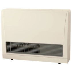
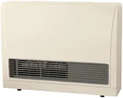
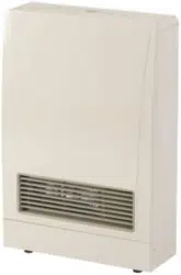
3. About the Direct Vent Furnace
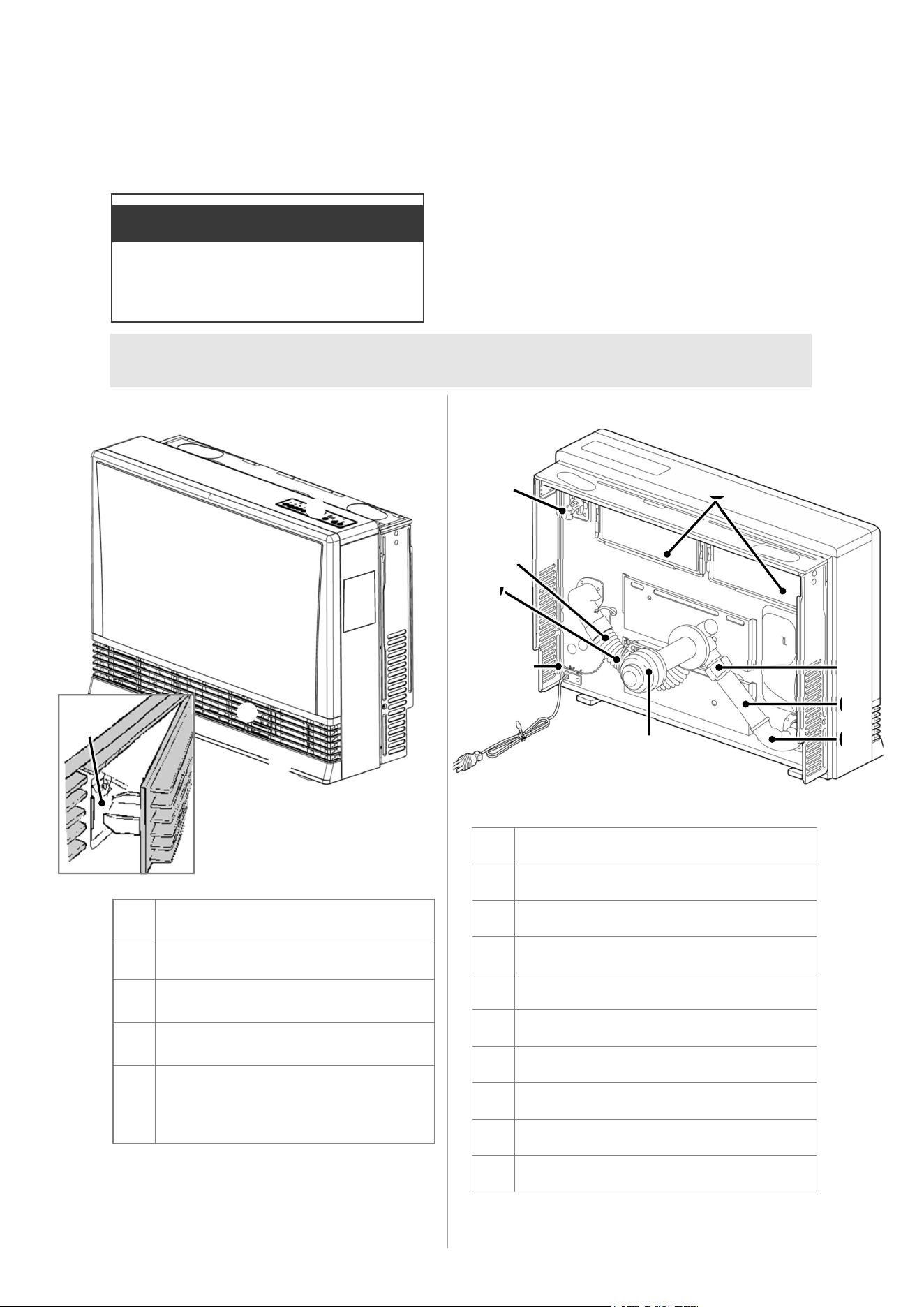
3.1 Main Components
Topics in this section
Main Components
Specifications
Dimensions
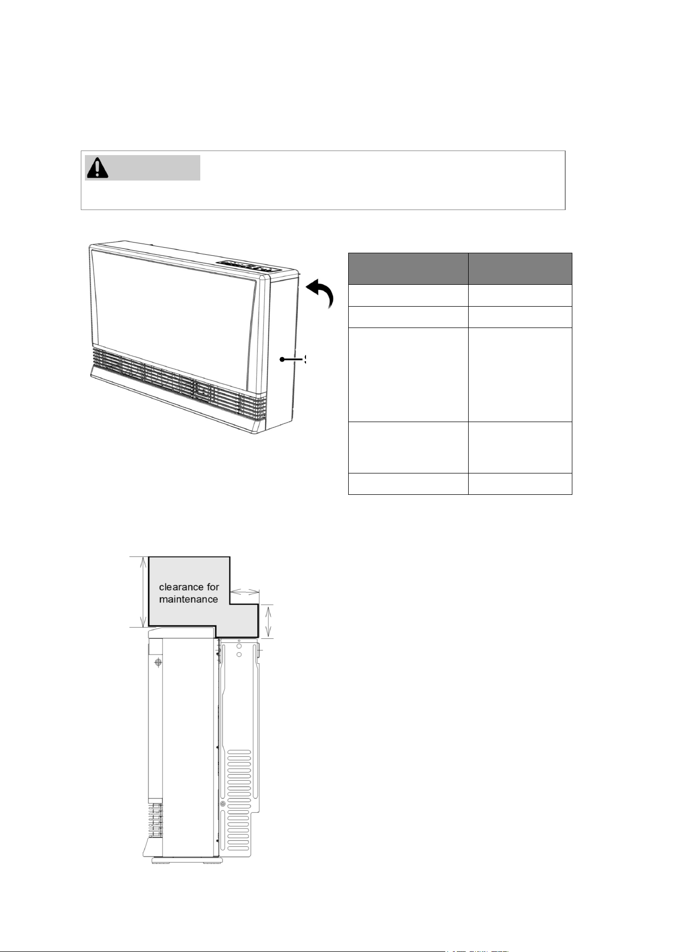
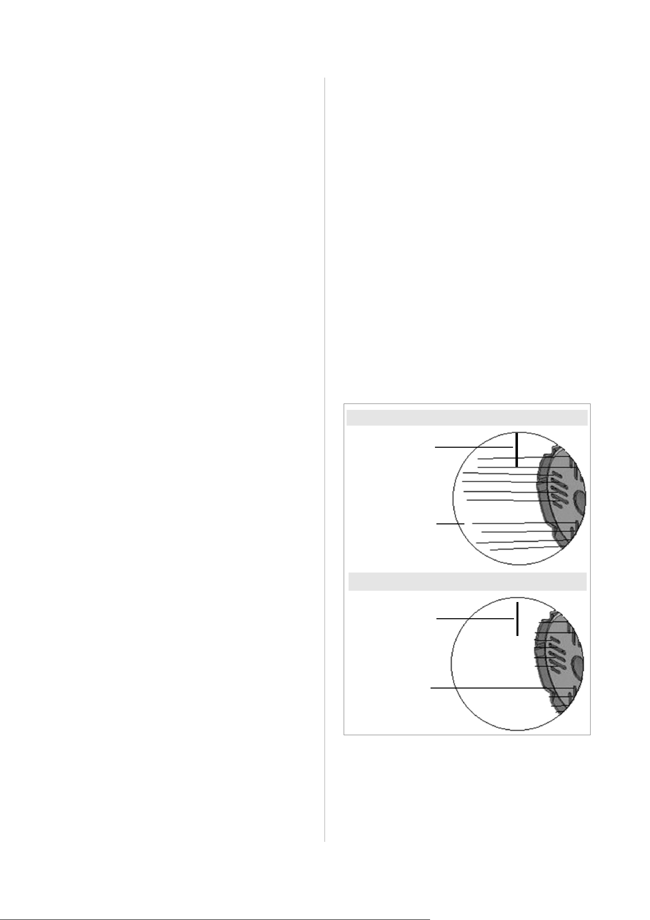
Front View
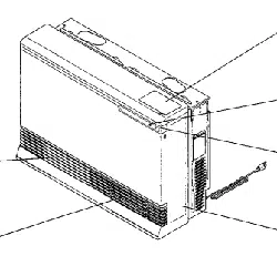
Back View
❶
Control Panel
❷
Warm Air Outlet
❸
Bottom Cover
❹
Humidifier (open panel to access)
❺
Rating plate (includes model number,
serial number, gas type, etc.). English
is on the right side; French is on the
left side.
❻
Air Filter
❼
Gas Connection (1/2 in./13 mm Male NPT)
❽
Combustion Air Intake Hose
❾
Plastic Tie for Air Inlet
❿
Room Temperature Sensor/Thermistor
⓫
Power Cord and Plug
⓬
Flue Manifold (Combustion/Exhaust)
⓭
Bent Elbow
⓮
Exhaust Pipe
⓯
Pipe Stopper
❹
❸
❶
❷
❾
Figure 2: Back View
Figure 1: Front View
❻
❼
❽
❿
⓫
⓬
⓭
⓯
⓮
❺
8 EX38DT Installation and Operation Manual
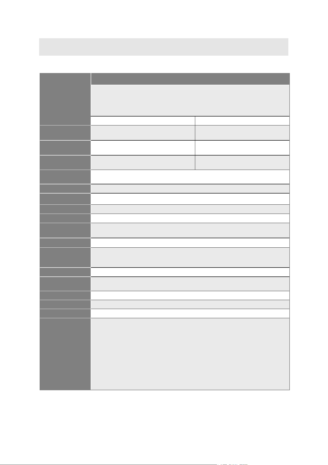
The efficiency rating of this furnace is a product thermal efficiency rating determined under continuous
operating conditions and was determined independently of any installed system.
Rinnai products are continually being updated and improved; therefore, specifications are subject to
change without prior notice.
EX38DT
Application
Approved for manufactured home (USA only) or mobile home or residential
installation convertible for use with natural gas and liquefied petroleum gases
(propane) when provision is made for the simple conversion from one gas to the
other. Approved for commercial setting. Approved for installation at altitudes up to
10,200 feet (3,109 m).
Natural Gas Liquid Propane Gas
Min. Supply Gas
Pressure
3.5 in. (89 mm) wc 8.0 in. (203 mm) wc
Max. Supply Gas
Pressure
10.5 in. (267 mm) wc 13.0 in. (330 mm) wc
Btu/h Input Low 13,200 High 38,400 Low 13,200 High 36,500
General
Description
Forced Combustion, Forced Convection, Flued Gas Furnace
Operation Push Button Electronic
Gas Connection 1/2 in. (13 mm) Male NPT
Gas Control Electronic
Burners Stainless Steel Bunsen Burner
Temperature
Control
Electronic Thermostat, Low, 60-80ºF (16-26°C) in 2ºF (1°C) Increments, High
Ignition System Electronic Spark Ignition
Flue System
The flue must be terminated to atmosphere with only flue components listed with the
furnace’s certification. Warranty will be voided if non-listed components are installed.
Humidifier Tray
Capacity - 6.3 pints (3,000 cc)
Electrical
Connections
AC 120 Volts, 60 Hz, 58 watts
Standby Power
0.7 watts
Weight
86 lbs (39 kg)
Sound Level
39-46 dB
Safety Features
Overheat: The furnace will automatically shut down when exceeding a
predetermined temperature.
Flame Failure: The furnace will automatically shut down if the burner flame is
extinguished.
Power Failure: The furnace will shut off the gas if it loses electrical power.
Power Surge Fuse: A glass fuse on the PC board protects against overcurrent. If
the fuse blows then all indicator lamps will be off.
Spark Detector: The furnace automatically shuts down if there is an abnormal
spark at ignition.
Fusible Link: In case the overheat feature does not prevent an overheat, then
the fusible link could break, shutting off the furnace.
3.2 Specifications
Table 2: Specifications
EX38DT Installation and Operation Manual 9
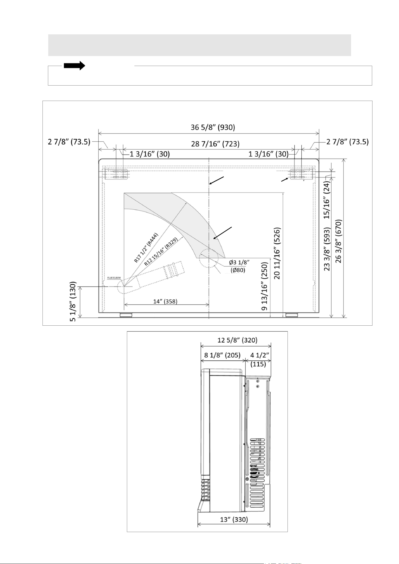
Measurements: inches (mm)
3.3 Dimensions
A full size wall template is provided on the furnace carton box. Do not discard until installation is complete.
IMPORTANT
Figure 3: Front View
Figure 4: Side View
Side View
Front View (Including Sample Wall Template Located on Furnace Carton Box)
Center of Furnace
Wall Bracket
Wall Opening
Position
Wall Opening Position
The hole center
should be within the
shaded area.
10 EX38DT Installation and Operation Manual
THIS SECTION IS INTENDED FOR THE
INSTALLER
Installer qualifications: A trained and qualified
professional must install the furnace, inspect it,
and leak test the direct vent furnace before use.
The warranty may be voided due to any improper
installation. The trained and qualified professional
should have skills such as: Gas sizing; Connecting
gas lines, valves, and electricity; Knowledge of
applicable national, state, and local codes;
Installing venting through a wall; and training in
installation of direct vent furnaces. Training for
Rinnai Direct Vent Furnaces is accessible online at
rinnaipro.myabsorb.com.
4. Installation
4.1 Installation
Guidelines
This furnace discharges a large volume of warm air
next to the floor. Any particles in the air such as
cigarette smoke could cause discoloration in nylon
carpets containing dyes or vinyl surfaces.
Rinnai suggests that a dedicated electrical circuit
with a 120V AC, 60 Hz, 10 amp power source be
used.
A test plug is provided for testing of manifold
differential pressure. It is located on the modulating
gas valve.
If you move to a different location, check the gas
type in your new area. The local gas authority will be
able to advise on local regulations.
The installation must conform with local codes or, in
the absence of local codes, with the National Fuel
Gas Code, ANSI Z223.1/NFPA 54, or the Natural
Gas and Propane Installation Code, CSA B149.1.
A manufactured home (USA only) or mobile home
OEM installation must conform with the
Manufactured Home Construction and Safety
Standard, Title 24 CFR, Part 3280, or, when such a
standard is not applicable, the standard for
Manufactured Home Installations, ANSI Z225.1, or
the standard for Gas Equipped Recreational Vehicles
and Mobile Housing, CSA Z240.4.
The furnace, when installed, must be electrically
grounded in accordance with local codes or, in the
absence of local codes, with the National Electrical
Code, ANSI/NFPA 70, or the Canadian Electrical
Code, CSA C22.1.
The furnace and its main gas valve must be
disconnected from the gas supply piping system
during any pressure testing of that system at test
pressures in excess of 1/2 psi (3.5 kPa).
The furnace must be isolated from the gas supply
piping system by closing its equipment shutoff valve
during any pressure testing of the gas supply piping
system at test pressures equal to or less than 1/2 psi
(3.5 kPa).
If the flooring is carpet or other combustible material
other than wood, then the furnace must be installed
on a metal or wood panel extending the full width
and depth of the furnace.
This furnace is only for use with the type of gas
indicated on the rating plate. This furnace is not
convertible for use with other gases unless a certified
kit is used. If conversion of the unit is needed,
conversions must be performed by a qualified
service provider at the owner’s expense.
The furnace should be correctly sized for the space it
is required to heat. It is recommended that an
industry standard BTU Heat Loss Calculation be
conducted to determine the proper sizing.
Follow the installations instructions and those in
section “6. Maintenance” for adequate combustion
and ventilation air.
This furnace is not designed to be built in.
DO NOT connect this furnace to a chimney flue
serving a separate solid-fuel burning appliance.
DO NOT obstruct the flow of combustion and
ventilation air.
Do not use substitute
materials. Use only parts
certified with the furnace.
When installing the direct vent furnace, follow these
guidelines:
This direct vent furnace is certified for
installation in residential applications,
commercial applications, and manufactured
(mobile) homes.
This furnace may be installed as an OEM
installation in a manufactured home (USA only)
or mobile home and must be installed in
accordance with the manufacturer’s
instructions and the Manufactured Home
construction and Safety Standard, Title 24
CFR, Part 3280, in the United States, or the
Mobile Home Standard, CAN/CSA Z240 MH
Series, in Canada.
This furnace may be installed in an aftermarket,
permanently located, manufactured home
(USA only) or mobile home, where not
prohibited by local codes.
If installation is at a location above 2,001 ft
(610 m), see section “4.4.8 Adjust the Gas
Pressure Settings.”
Furnace input ratings are based on sea level
operation and need not be changed for
operation up to 2,000 ft (610 m) elevation.
WARNING
Topics in this section
Installation Guidelines
What You Will Need
Choose an Installation Location
Installation Steps
Post-Installation Checklist
EX38DT Installation and Operation Manual 11
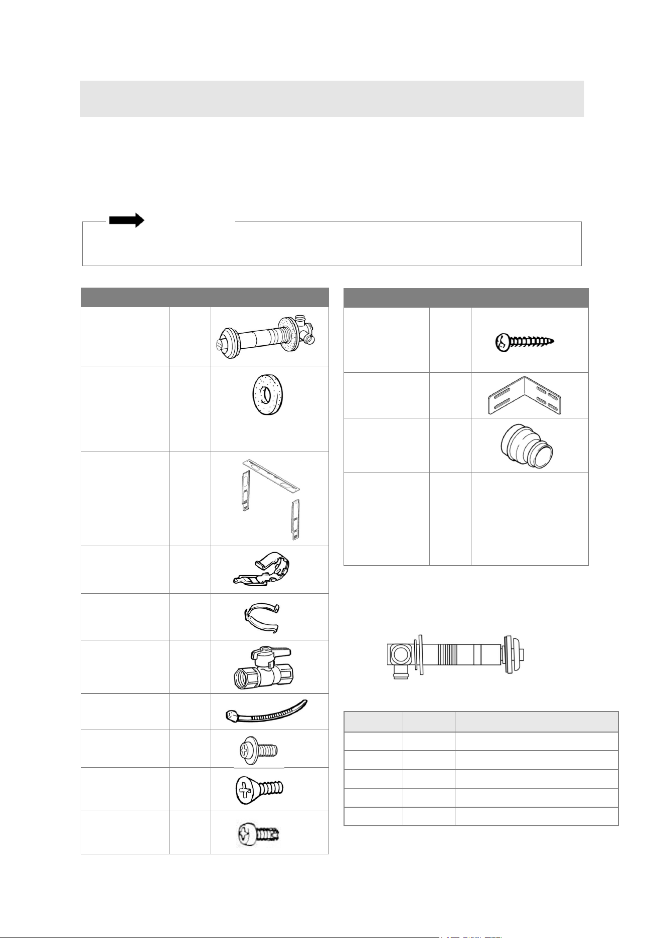
Unpack the Rinnai Direct Vent Furnace package and verify the following contents are included. If
any items are damaged or missing, contact your local dealer/distributor or call Rinnai Customer
Care at 1-800-621-9419.
4.2 What You Will Need
4.2.1 Items Included
Product Qty Image
Flue Manifold
"A" Vent Kit
(FOT-151)
1
Spare Rubber
Seal
("A" Flue Units
Only)
1
Back Spacer
Set
1
1
Pipe Stopper
A&S
2
Insulation Clip 1
Manual Valve 1
Plastic Tie for
Air Inlet
1
Screw (M5) (For
Wall Brackets)
4
Screw (M4)
(For Flue
Manifold)
3
Screw (M4)
(For Back
Spacer Set)
7
Product Qty Image
Wood Screw
(M 4.8 x 32)
(Wall Bracket
Screws)
7
Wall Brackets
2
Flue Adapter
(Attached to
Unit)
1
Rinnai Direct
Vent Wall
Furnace
Installation and
Operation
1 Image not shown
(For Weatherboard
Installation)
Table 3: Items Included
Name Kit No. Fits Walls
S Vent Kit FOT-150 3 - 4 1/2 in. (75 - 115 mm)
A Vent Kit FOT-151 4 1/2 - 9 1/2 in. (115 - 240 mm)
B Vent Kit FOT-152 9 1/2 - 15 3/4 in. (240 - 400 mm)
C Vent Kit FOT-153 15 3/4 - 23 5/8 in. (400 - 600 mm)
D Vent Kit FOT-154 23 5/8 - 31 1/2 in. (600 - 800 mm)
Vent Kit “A” is included with the furnace.
Additional Flue Manifolds
The following flue manifold sizes are available
for different wall thicknesses:
Table 4: Additional Flue Manifolds
A full size wall template is provided on the furnace carton box. Do not discard until installation is
complete.
IMPORTANT
1
The color of the back spacers is a slightly different shade than the color of the furnace.

12 EX38DT Installation and Operation Manual
Air surrounding the venting, and vent
termination(s) is used for combustion and must
be free of any compounds that cause corrosion
of internal components. These include corrosive
compounds that are found in aerosol sprays,
detergents, bleaches, cleaning solvents, oil
based paints/ varnishes, and refrigerants.
The furnace, venting, and vent termination(s)
should not be installed in any areas where the
air may contain these corrosive compounds. If it
is necessary for a furnace to be located in
areas that may contain corrosive compounds,
the following instructions are strongly
recommended.
IMPORTANT CONSIDERATIONS:
DO NOT install in areas where air for
combustion might be contaminated with
chemicals.
Before installation, consider where air has
the ability to travel within the building to the
furnace.
Terminate the unit as far away as possible
from any air inlet vents. Corrosive fumes
may be released through these vents
when air is not being brought in through
them.
Chemicals that are corrosive in nature
should not be stored or used near the
furnace or vent termination.
Damage and repair due to corrosive
compounds in the air is not covered by
warranty.
Pipe Wrenches (x2)
Adjustable Pliers
Screwdrivers (x2)
Wire Cutters
Gloves
Safety Glasses
Level
Soap or Gas Leak Detector Solution
Approved Venting
Teflon Tape (Recommended) or Pipe
Compound
The following field-supplied items may be
needed:
Gas Manometer
Hammer Drill with Concrete Bits
Saw
Threading Machine with Heads and Oiler
Core Drill with Diamond Head
Torch Set
Steel Pipe Cutter
Concrete Wall Anchors
Optional Pipe Cover
Single Gang Electrical Box
Wire Nuts
4.2.2 Items Needed
(Field-Supplied)
When selecting an installation location, you
must ensure that all direct vent furnace and
venting clearances will be met and that the vent
length will be within required limits. You must
also consider the installation environment.
Requirements for the gas line and electrical
connection can be found in their respective
installation sections in this manual.
4.3 Choose an
Installation Location
4.3.1 Environment
EX38DT Installation and Operation Manual 13
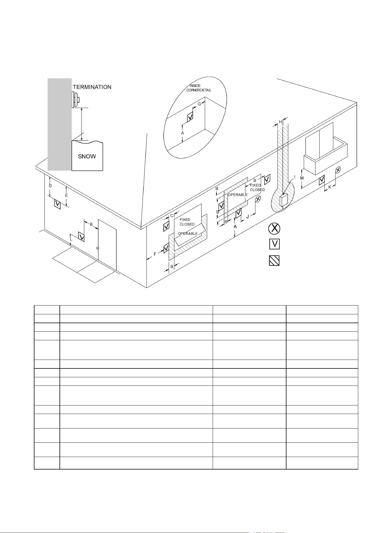
4.3.2 Clearances
AIR SUPPLY INLET
VENT TERMINAL
AREA WHERE
TERMINAL IS NOT
PERMITTTED
Clearance in
Ref. A also
applies to
anticipated
snow line
Flue Terminal Clearances
Figure 5: Flue Terminal Clearances
Table 5: Clearances
[1] A vent shall not terminate directly above a sidewalk or paved
driveway that is located between two single family dwellings and
serves both dwellings.
[2] Permitted only if veranda, porch, deck, or balcony is fully open on
a minimum of two sides beneath the floor.
For clearances not specified in ANSI Z223.1/NFPA 54, clearances
are in accordance with local installation codes and the requirements
of the gas supplier.
Clearance to opposite wall is 24 inches (60 cm).
Ref
Description
Canadian Installations US Installations
A Clearance above grade, veranda, porch, deck, or balcony 12 inches (30 cm) 12 inches (30 cm)
B Clearance to window or door that may be opened 12 inches (30 cm) 9 inches (23 cm)
C Clearance to permanently closed window * *
D
Vertical clearance to ventilated soffit, located above the terminal
within a horizontal distance of 2 feet (61 cm) from the center line
of the terminal
* *
E Clearance to unventilated soffit * *
F Clearance to outside corner * *
G Clearance to inside corner * *
H
Clearance to each side of center line extended above meter/
regulator assembly
3 feet (91 cm) within a height
15 feet (4.5 m) above the
meter/regulator assembly
*
I Clearance to service regulator vent outlet 36 inches (91 cm) *
J
Clearance to nonmechanical air supply inlet to building or the
combustion air inlet to any other appliance
12 inches (30 cm) 9 inches (23 cm)
K Clearance to a mechanical air supply inlet 6 feet (1.83 m)
3 feet (91 cm) above if within
10 feet (3 m) horizontally
L
Clearance above paved sidewalk or paved driveway located on
public property
7 feet (2.13 m) [1] *
M Clearance under veranda, porch, deck, or balcony 12 inches (30 cm) [2] *
14 EX38DT Installation and Operation Manual
When determining where to install the direct vent furnace, the clearances to combustibles shown in
the figures below must be followed.
Clearances to Combustibles
Service Clearances
Clearances to access the furnace during
servicing are 10 in. (254 mm) from the sides,
40 in. (1 m) from the front, and the area shown
above the furnace in the figure to the left.
Rinnai recommends 10 in. (254 mm) clearance
from the top and on both sides for servicing.
Location
Clearances to
Combustibles
Top
0 in. (0 mm)
Bottom/Ground
0 in. (0 mm)
Front (Panel)
40 in. (1 m)*
*Does not include
flooring material or
carpeting less than
1.2 in. (30 mm) in
height.
Back (Including Back
Spacer)
0 in. (0 mm)
Sides (Left and Right) 2 in. (50 mm)
Top
Bottom
Back
If clearances are not met, damage to the property or direct vent furnace may occur.
CAUTION
Table 6: Clearance to Combustibles
Figure 6: Clearances
Measurements: inches (mm)
Figure 7: Service Clearances
Front
6 (153)
10”
(254 mm)
10 (254)
3”
(76 mm)
3 (76)
Side
EX38DT Installation and Operation Manual 15
Use this checklist to ensure you have selected the correct location for the direct vent furnace.
4.3.3 Installation Location Checklist
The furnace is not exposed to corrosive compounds in the air.
The furnace location complies with the required clearances.
The planned venting termination/air intake location meets the clearances.
Indoor air is not being used for combustion.
A standard 3 prong 120 VAC, 60 Hz properly grounded wall outlet is available.
The installation must conform with local codes or, in the absence of local codes, with the
National Fuel Gas Code, ANSI Z223.1/NFPA 54, or the Natural Gas and Propane
Installation Code, CSA B149.1. If installed in a manufactured home, the installation must
conform with the Manufactured Home Construction and Safety Standard, Title 24 CFR,
Part 3280 and/or CAN/SCA Z240 MH Series, Mobile Homes.
Leave the entire manual taped to the furnace or give the manual directly to the
consumer.
16 EX38DT Installation and Operation Manual
4.4 Installation Steps
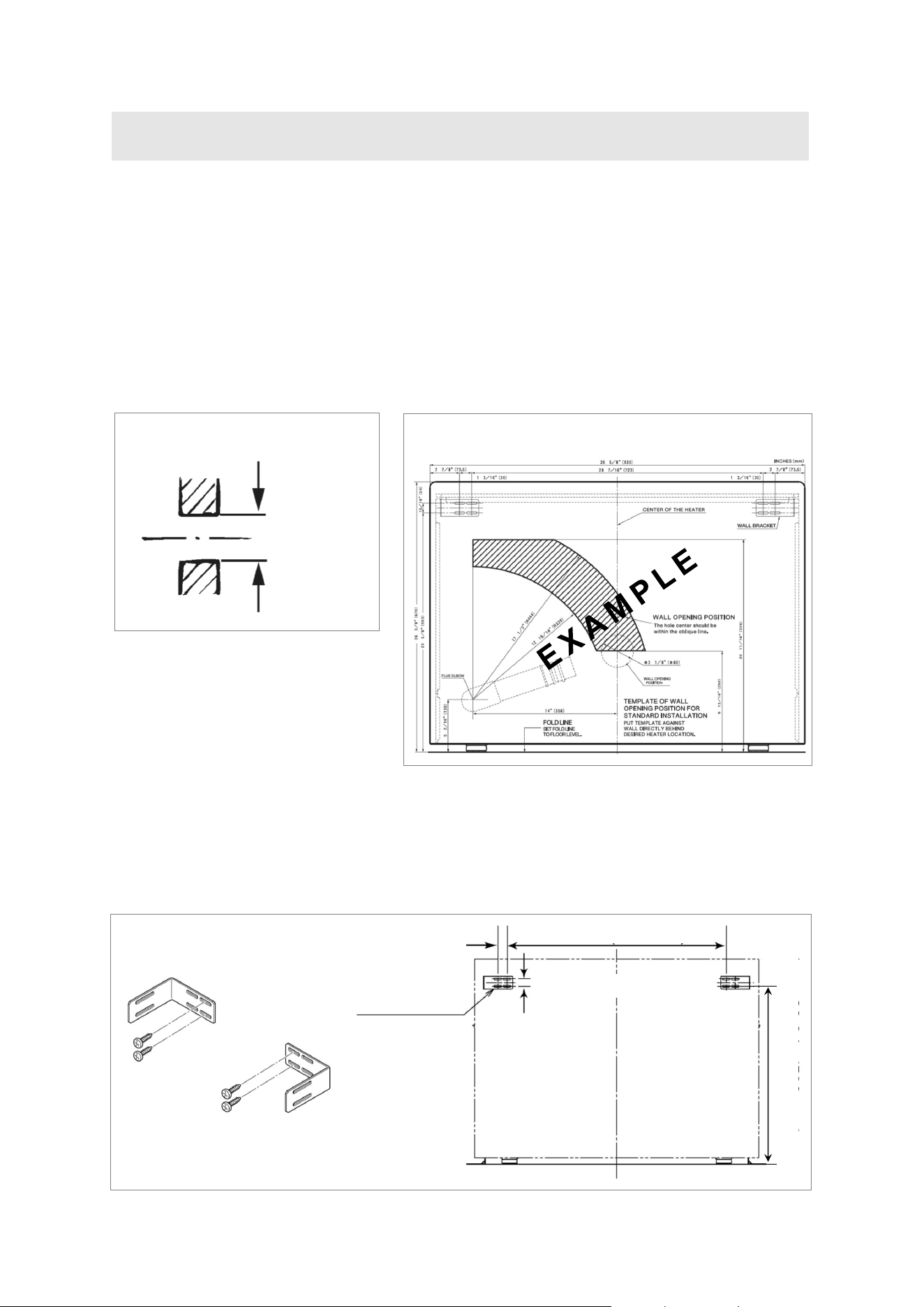
4.4.1 Drill the Flue Hole
Ensure that there are no gas or water lines, or electrical circuits in the wall location where the flue
hole is to be drilled.
Drill the flue hole using a Ø3 1/8 in. (Ø80 mm) drill. A template is provided on the furnace carton
box. The center of the hole must be located anywhere within the shaded area, unless extension kits
are used. See the dimensions diagram.
For weatherboard walls, drill through the center of the weatherboard from the outside first and then
through the plasterboard.
Figure 8
4.4.2 Attach Wall Brackets
Attach the wall brackets as shown. A template is provided.
Figure 9
Example template located on furnace carton box
Figure 10
Ø3 1/8 in.
(Ø80 mm)
Flue Hole
15/16 in. (24 mm)
1 3/16 in. (30 mm)
28 7/16 in. (723 mm)
23 3/8 in. (593 mm)
Wall Bracket
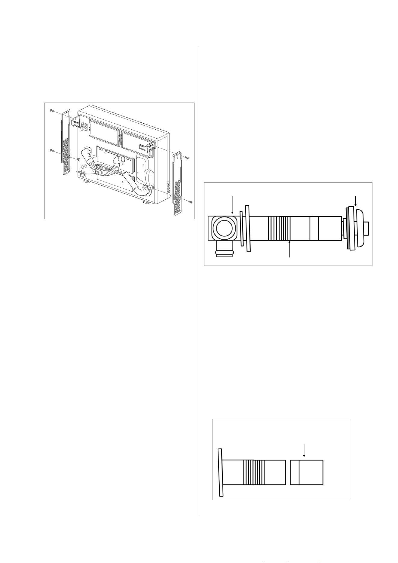
EX38DT Installation and Operation Manual 17
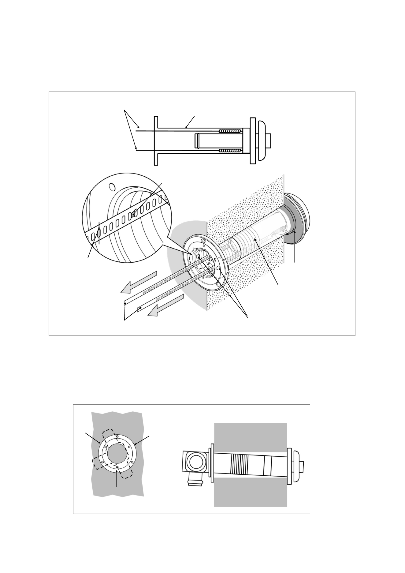
1. Disassemble the flue manifold
The flue consists of 3 parts:
sleeve
inside connection
outside terminal
Disassemble the flue manifold by first
pulling out the inside connection. To
remove the outer terminal pull and release
the two internal ties and then pull out the
outer terminal.
Clearance to combustibles for the sleeve
and flanges is zero inches.
2. Adjust the sleeve length
Measure wall thickness through previously
drilled Ø3 1/8 inch (Ø80 mm) hole.
The end of the sleeve should protrude 3/16 -
3/8 inch (5-10 mm) from the outside wall.
The sleeve is threaded for adjustment.
Adjust the sleeve length to wall thickness
plus 3/16 - 3/8 inch (5-10 mm).
NOTE: Do not extend beyond the red line.
For other than the “S” type flue manifold, if a
shorter length is necessary an extension can
be removed. Cut the outer plastic laminate
(with a utility knife or similar) and remove the
extension. The metal should not be cut.
Inside Connection
Sleeve
Terminal
Remove extension
if necessary
Guidelines:
The flue manifold must exhaust to the
outside. Do not exhaust into other
rooms.
The flue manifold is not designed to be
positioned under floors or below the
furnace.
The termination cannot be vertical.
This furnace can only be used with one
of the five types of Rinnai flue kits. The
flue kits and their dimensions are listed
in section “4.2.1 Items Included.”
Refer to “Flue Terminal Clearances” in
section “4.3.2 Clearances.”
4.4.4 Install the Flue
Manifold
Instructions:
Figure 13
Figure 12
4.4.3 Attach Back Spacers
Attach side back spacers to both sides of the
furnace with 2 screws each.
Figure 11

18 EX38DT Installation and Operation Manual
3. Install the Sleeve.
Attach the sleeve to the inside wall using 3 screws arranging the flange so that the marking
“TOP” is at the top. The flange is offset 2° to allow the condensate drain to the outside.
Apply silicone sealing evenly around the perimeter of the outside sleeve to avoid water intrusion.
4. Install the Terminal.
Check that the terminal seal is in place. For weatherboard walls, add the second seal next to the
terminal seal to compensate for weather board angle. Adjust the second seal to make sure “Top”
marking of the second seal is located at the top or “Ʌ” marking is aligned with “V” marking on the
terminal.
From the outside insert the terminal into the sleeve with the marking “TOP” at the top. The left
hand side locking tie should be marked “LEFT”.
3 screws
Sleeve should extend
3/16 - 3/8 in (5-10 mm)
Figure 14
Indoor
Outdoor
Apply silicone
sealing evenly
around the
perimeter.
Top Terminal
seal
Apply silicone
sealing evenly
around the entire
seal.
Put silicone sealing evenly around the perimeter without any
gaps between the terminal seal and rough wall surface.
Figure 15
Locking tie
(Ʌ)
(V)
Terminal
EX38DT Installation and Operation Manual 19
5. Lock the ties.
Pulling hard on the left and right hand ties, clip the ties over the notches inside the sleeve. You
should be able to pull the ties 2 or 3 notches past the starting point. Cut the ties, leaving about
1 1/4 inch (30 mm) past the notch. Bend the ties back into the sleeve and parallel to the wall.
6. Insert Inside Connection Assembly.
Push the assembly into the terminal tube, ensuring that the seal is in place on the inner tube.
Attach the inside connection with 3 screws. The inner connection can still be turned to install the
screws.
3 screws
Figure 17
Locking ties
Sleeve
Figure 16
Top
Sleeve
Clip the ties over
the inside sleeve
and cut the ties
sticking out.
Pull hard on the left and right hand ties.
Locking ties (2 locations)
Locking tie
20 EX38DT Installation and Operation Manual
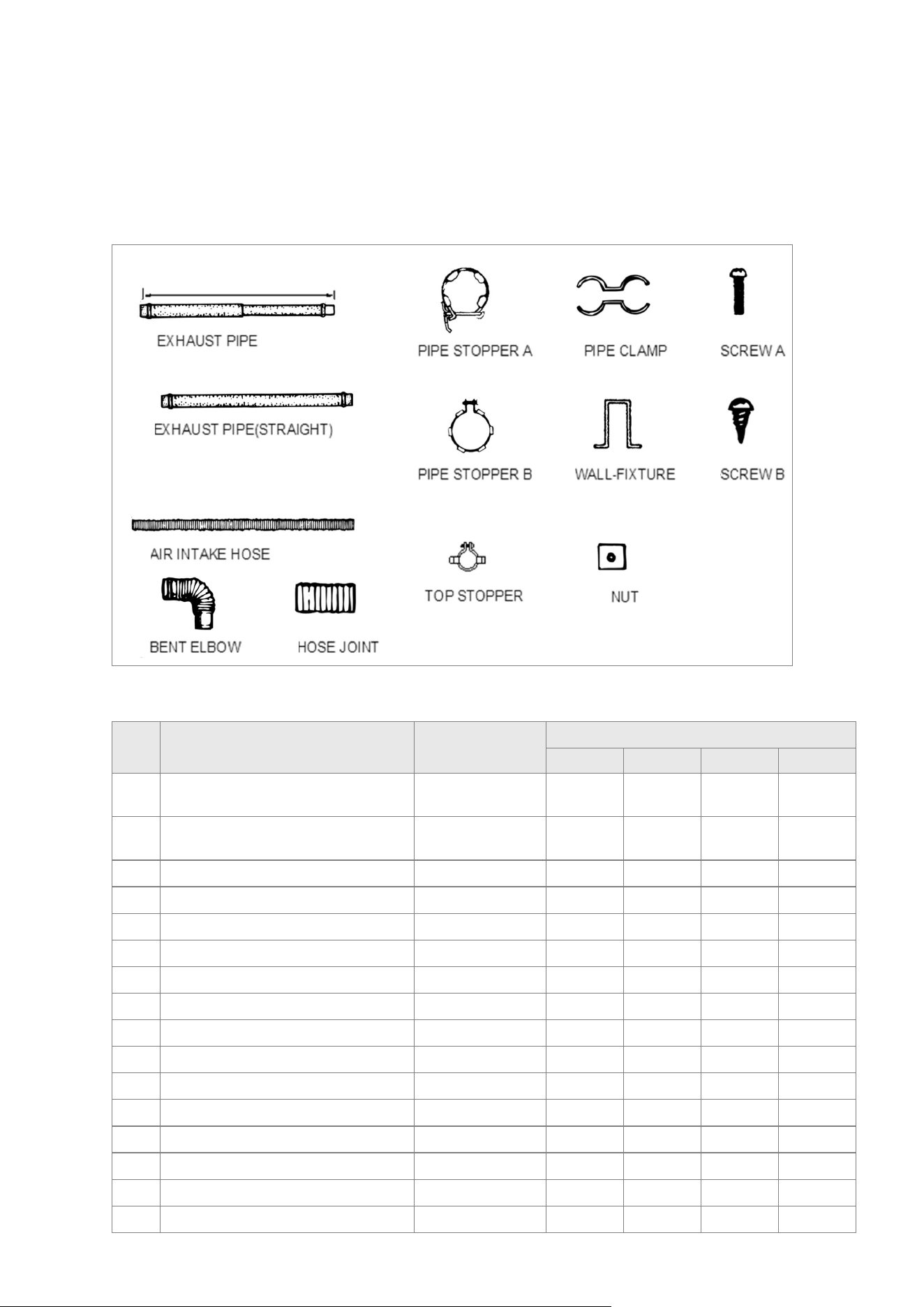
4.4.5 Install the Optional Extension Kit
Item Description Part Number
Extension Kit Part Number
FOT-102 FOT-103 FOT-114 FOT-115
1 Exhaust Pipe (adjustable)
12.2-21.1 in. (311-536 mm)
FOT 111-1 1
1 Exhaust Pipe (adjustable)
21.9-40.4 in. (556-1,026 mm)
FOT 112-1 1 1
2 Exhaust Pipe - 39.4 in. (1,000 mm) FOT 114-3 1
3 Air Intake Hose - 29.5 in. (750 mm) RHF 1000-130-e 1
3 Air Intake Hose - 51.2 in. (1.3 m) RHF 1000-130-b 1
3 Air Intake Hose - 90.6 in. (2.3 m) RHF 1000-130-f 1
4 Bent Elbow FOT 025-4 1
5 Hose Joint RFOT 226-001 1 1 1
6 Pipe Stopper A 1001F-250 1 1 2 2
7 Pipe Stopper B FOT 111-6 1 1 1
8 Top Stopper FOT 062-7 1 1 1
9 Pipe Clamp FOT 064-11 2 Sets 3 Sets 4 Sets
10 Wall Fixture FOT 064-12 2 3 4
11 Nut FOT 062-10 2 3 4
12 Screw A ZAA0420SC 2 3 4
13 Screw B CP-30408 4 6 8
Extension kits are available to extend the exhaust line and air intake hose between the manifold and
direct vent furnace. Follow the steps in this section if the optional extension kit was purchased for
your Direct Vent Furnace model.
Extension Kit Contents
Verify the following contents are included in the extension kit:
Table 7: Extension Kit Contents
Figure 18
❶
❾ ❻
❸
❷
❺
❹
❽
❼
⓬
⓫
⓭
❿
EX38DT Installation and Operation Manual 21
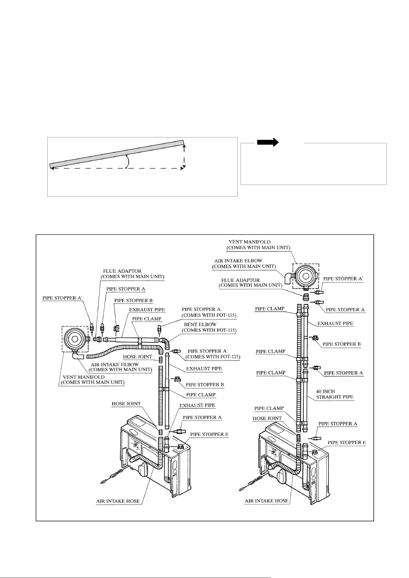
Guidelines
1. The maximum vent length is 13 feet (4 m) with 3 bends. The bent pipe attached to the furnace
does not count toward the max limit of 3 bends.
2. Horizontal sections should be sloped 3º to drain condensate. (3º equals 2/3 inch drop per foot of
vent.) The direction should be to the outside (if local codes allow) or toward the furnace.
3. Do not allow any low points in the exhaust line where condensate will collect.
4. Vent extensions installed in unconditioned air space.
5. Clearances:
Exhaust pipe to combustibles: 1 in. (25.4 mm)
Exhaust pipe to non-combustibles: 0 in. (0 mm)
Figure 19
NOTE
Configurations
The EX38DT is capable of two vent length
settings:
Short Vent: 0 - 7 ft + 1 elbow
Long Vent: 7 ft + 1 elbow - 13 ft + 3 elbows
Slope horizontal sections 3º (2/3 inch drop per foot of vent.)
3°
1 Ft
2/3 in.
Correct Configurations
Figure 20
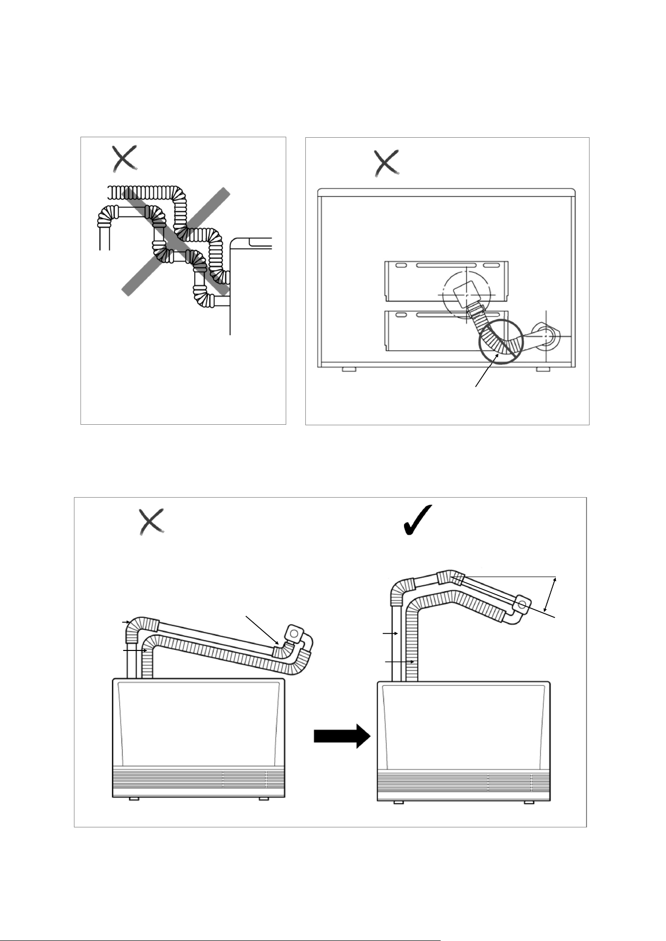
22 EX38DT Installation and Operation Manual
Too many bends (limit is 3)
Air intake hose is above
exhaust pipe.
Do not allow any low points in the exhaust line.
Incorrect Configurations
NOT CORRECT
Back of Furnace
NOT CORRECT
CORRECT
NOT CORRECT
Figure 21
Figure 22
Figure 23
90° Elbow Up
Configuration
Slope horizontal
sections 3°
downward
3°
Intake
Exhaust
Intake
Exhaust
EX38DT Installation and Operation Manual 23
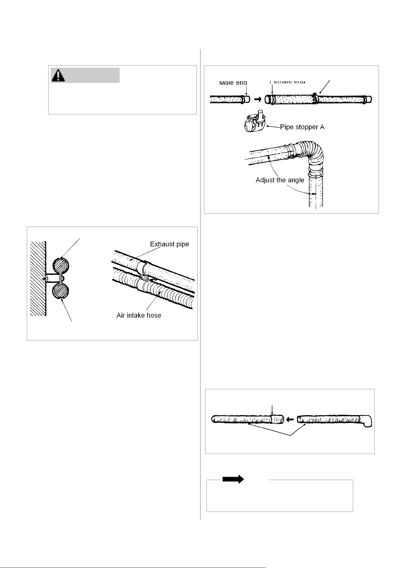
Use the pipe stoppers, connectors, clamps,
and screws according to these instructions in
order to ensure no leakage of exhaust gases.
Exhaust pipe
Exhaust pipe
Air intake hose
Air intake hose
Pipe stopper A
Pipe stopper B
Male end
Female end
Adjust the angle
Hose joint
Air intake hoses
Do not cut the intake hose. Cutting the
intake hose may result in noise.
Instructions:
1. Install the Clamps:
Both the exhaust line and air intake hose
are supported by clamps which are attached
to the wall. A wall fixture can be used to
offset the clamp from the wall. Use Screw B
to attach the wall fixture to the wall. If the
wall fixture is not used then use Screw A
and the nut to attach the clamp to the wall.
The air intake hose should always be
underneath the exhaust line so that in case
the air line sags it will not come into contact
with the exhaust line.
2. Install the Exhaust Line:
The exhaust line is connected between the
bent pipe at the rear of the furnace and the
exhaust port on the flue manifold.
To connect exhaust pipes with other
straight pipes or bends, fit the male end
into the female end. Use pipe stopper A
to clamp the connection.
Use pipe stopper B to fix the length on
the adjustable exhaust pipes. Do not
extend these pipes beyond the red line.
Do not cut the exhaust pipe. Use the
adjustable pipes if necessary.
To bend the elbow, insert exhaust pipes
into both ends for additional leverage.
Bend to desired angle.
Do not straighten the bent pipe attached
to the furnace.
3. Connect the Air Intake Hose:
The air intake hose is connected between
the air connection at the rear of the furnace
and the air intake port on the flue manifold.
Push the air intake hose onto the flue
manifold and secure with the plastic cable
tie.
Join air intake hoses by screwing the hose
joint half of its length into the air intake hose
and then screwing another air intake hose
into the hose joint.
The lengths of the air intake hose and the
exhaust pipe must be the same in order for
the furnace to operate properly. The hose
can be cut to the required length. Deburr all
rough edges. Do not cut the hose attached to
the furnace.
Support the air intake hose with pipe clamps.
NOTE
CAUTION
Figure 26
Figure 25
Figure 24
24 EX38DT Installation and Operation Manual
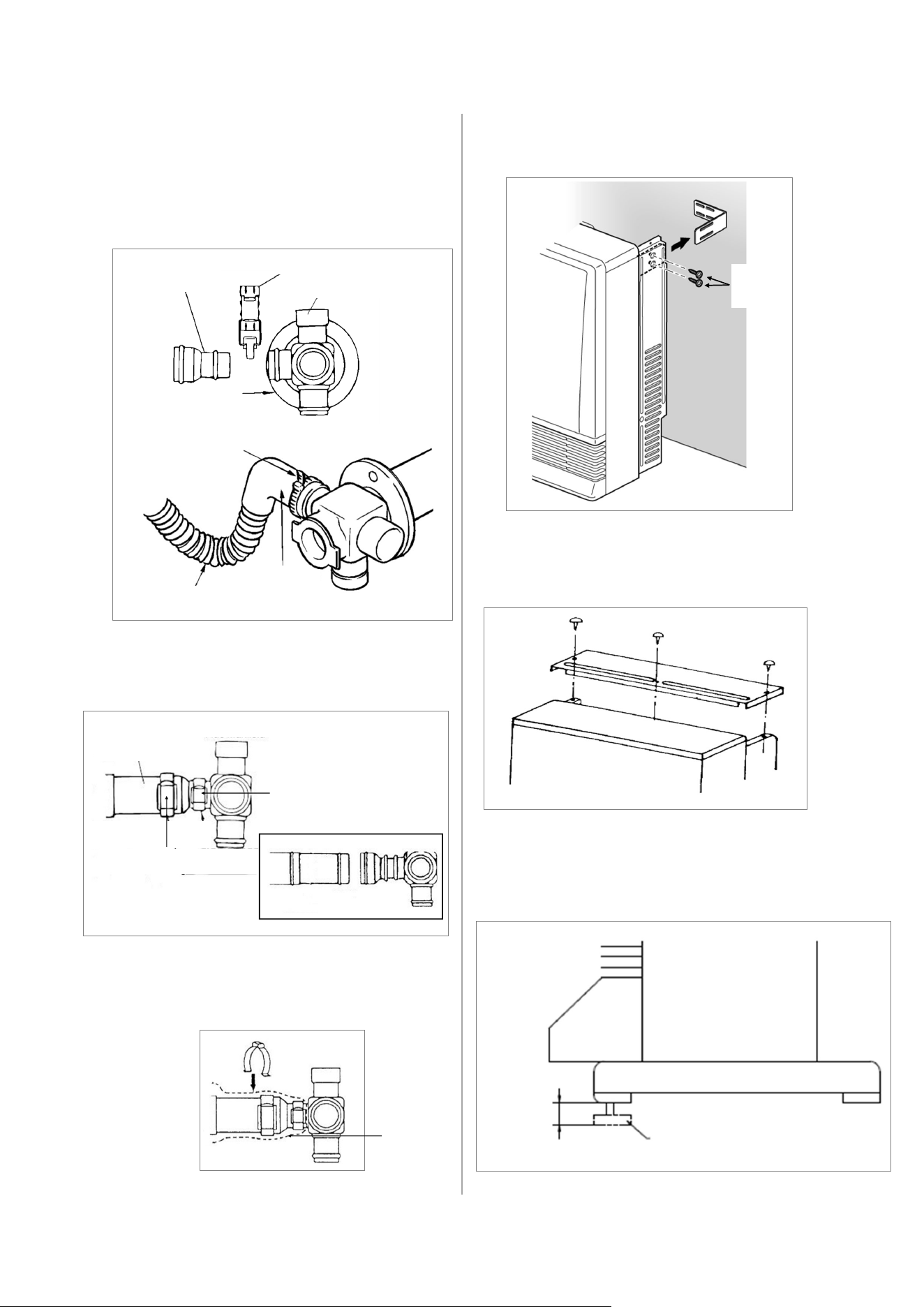
4.4.6 Connect the Direct Vent Furnace
1. Attach flue adapter to the flue manifold with
pipe stopper S.
2. Attach the air inlet hose to the flue
manifold. Secure with plastic tie. The
unused inlet is plugged with the rubber cap
supplied on the manifold.
3. Connect the vent sliding tube with pipe
stopper S and A.
4. Slide the insulation sleeve up to the flue
manifold and slip the securing clip over the
sleeve as shown.
5. Attach the furnace to the wall brackets,
using 2 screws at each bracket.
6. Attach the back spacer with 3 screws to the
top of the furnace.
7. If necessary, the furnace can be leveled
using the adjustable legs under the front
right and left legs.
Up to
3/8 in.
(10 mm)
Adjustable Leg
Pipe Stopper S
Flue Adapter
Flue Manifold
Plastic Tie
Inlet Hose
Inlet
Elbow
Flue Manifold
Sliding Tube
Pipe Stopper A
Pipe Stopper S
Figure 28
Figure 27
Figure 29
Figure 31
Figure 30
Screw
(M5)
Figure 32
Insulation
Sleeve
EX38DT Installation and Operation Manual 25
4.4.8 Adjust the Gas
Pressure Settings
The gas supply line shall be gas tight,
sized and so installed as to provide a
supply of a gas sufficient to meet the
maximum demand of the furnace without
loss of pressure.
A shut off valve and appliance connector
valve should be installed in the upstream
of the gas line to permit servicing.
Flexible pipe and any appliance connector
valve used for gas piping shall be types
approved by nationally recognized
agencies.
Any compound used on the threaded joint
of the gas piping shall be a type which
resists the action of liquefied petroleum
gas (propane).
After completion of gas pipe connections
all joints including the furnace must be
checked for gas tightness by means of
leak detector solution, soap and water, or
an equivalent nonflammable solution, as
applicable. (Since some leak test
solutions, including soap and water, may
cause corrosion or stress cracking, the
piping shall be rinsed with water after
testing, unless it has been determined that
the leak test solution is non-corrosive.)
Check the gas supply pressure
immediately upstream at a location
provided by the gas company. Supplied
gas pressure must be within the limits
shown in section “3.2 Specifications.”
Refer to an approved pipe sizing chart if in
doubt about the size of the gas line.
Complete these instructions for altitude and
vent length.
Default altitude: 0 - 2,000 ft.
Default vent length: 0 - 7 ft. + 1 Elbow
For altitudes greater than 2,000 ft or
installations with vent lengths longer than
7 ft, refer to Table 8: Gas Pressure on the
next page.
For high altitude installations in Canada, the
conversion shall be carried out by a
manufacturer’s authorized representative, in
accordance with the requirements of the
manufacturer, provincial or territorial authorities
having jurisdiction and in accordance with the
requirements of CAN/CGA-B149.1 or CAN/
CGA-B149 installation codes.
4.4.7 Connect the Gas
When connecting the gas valve or other gas
components in the gas line, use a backup
wrench to ensure the connection is gas tight.
WARNING
CAUTION
Do not touch any other areas on the PC
board besides the “SW” switches while
power is supplied to the furnace. Parts
of the PC board are supplied with 120
volts AC.
Do not insert hands or objects into the
circulation fans while they are running.
Injury or mechanical malfunction may
occur.
Do not touch the areas at or near the
exhaust. This area becomes very hot
and could cause burns.
The regulator has been factory pre-set. If
the pressure is incorrect, contact Rinnai
technical support.
IMPORTANT
26 EX38DT Installation and Operation Manual
Instructions:
Natural Gas
Short Vent Lengths:
0 - 7 ft (2 m) + 1 elbow (A1 - A4)
Long Vent lengths:
7 ft (2 m) +1 elbow - 13 ft (4 m) + 3 elbows (A5 - A8)
Propane Gas
Short Vent Lengths:
0 - 7 ft (2 m) + 1 elbow (L1 - L4)
Long Vent lengths:
7 ft (2 m) +1 elbow - 13 ft (4 m) + 3 elbows (L5 - L8)
Code A1 / A5 A2 / A6 A3 / A7 A4 / A8 L1 / L5 L2 / L6 L3 / L7 L4 / L8
Altitude
0-2,000 ft
0-610 m
2,001-5,400 ft
611-1,646 m
5,401-7,800 ft
1,647-2,377 m
7,801-10,200 ft
2,378-3,109 m
0-2,000 ft
0-610 m
2,001-5,400 ft
611-1,646 m
5,401-7,800 ft
1,647-2,377 m
7,801-10,200 ft
2,378-3,109 m
Manifold test
pressure - W.C.
Low
1.69 in.
(43 mm)
1.59 in.
(40 mm)
1.49 in.
(38 mm)
1.43 in.
(36 mm)
3.21 in.
(82 mm)
3.01 in.
(76 mm)
2.85 in.
(72 mm)
2.73 in.
(69 mm)
Manifold test
pressure - W.C.
High
3.8 in.
(96 mm)
3.0 in.
(76 mm)
2.7 in.
(68 mm)
2.5 in.
(62 mm)
6.4 in.
(162 mm)
5.6 in.
(143 mm)
5.1 in.
(129 mm)
4.6 in.
(116 mm)
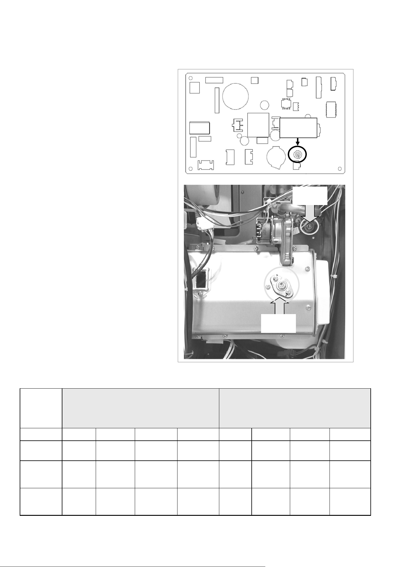
1. Turn off the gas and the power
supply.
2. Remove the 3 screws that hold the
front panel. Lift the panel straight up
and then remove.
3. Remove test port screws (1/8 NPT
tap) with 3/16 Allen wrench located
at gas valve and burner cover.
Install two 1/8 in. barb fittings (field-
supplied). Attach dual port
manometer to the test ports as
shown. Ensure that the manometer
is properly calibrated.
4. Turn on the gas and power supply
to the furnace.
5. Ensure “Set Back” feature has been
deactivated. (“Set Back” feature is
active by default.)
6. With the unit in the Off position,
press the Test Switch at the bottom,
right of PC board until it beeps.
7. Select the correct code for gas type,
altitude, and vent length on the LED
display using ▲ and ▼ buttons.
Refer to the table below.
Table 8: Gas Pressure
Figure 33
Negative
Port
Positive
Port
PCB Test
Switch
EX38DT Installation and Operation Manual 27
8. Press the Test Switch twice to enter the
gas code into memory.
The LED display turns blank and the unit
returns to the normal off mode. You are
now ready to program your correct low
fire and high fire gas pressure setting.
Follow the procedure below for setting
the manifold gas pressure. Do not adjust
gas pressure on this furnace using the
screw on top of the gas valve.
9. Press the ON/OFF button to operate the
furnace.
10. Press the Test Switch twice to change to
the low pressure mode. The LED will
display “PL”.
11. Compare the pressure reading on the
manometer to the desired manifold test
pressure (low) for your gas type, altitude
and vent length. If necessary adjust the low
fire pressure using the ▲ and ▼ buttons.
12. Press the Test Switch. The LED will display
“PH” indicating high fire mode.
13. Compare the pressure reading on the
manometer to the desired manifold test
pressure (high) for your gas type, altitude
and vent length. If necessary adjust the
high fire pressure using the ▲ and ▼
buttons.
14. Press the ON/OFF button again. The LED
display turns blank and the furnace returns
to the normal OFF mode.
15. Remove manometer and two barb fittings,
and install Allen head screws. Operate the
unit and follow steps A, B, and C below.
A. Check for Gas Leaks at the Test
Points.
16. Install the front panel.
17. If doing a gas type conversion, place the
new conversion rating plate (label) on the
front cover.
B. Check the Normal Operating
Sequence:
When you press the ON/OFF button,
the LED display will illuminate, the
combustion fan will begin to run, and
the spark will ignite the main burner.
This furnace has an automatic
ignition system. When the main
burner has lit, the combustion lamp
will glow red, and the spark will stop.
C. Visually Inspect the Flame:
Check that the burner flames are
operating normally. The flame can be
seen through the circular window.
When operating normally the burner
flame should appear as long, clear,
blue, stable, streaks. Yellow flames
or an orange color is abnormal and
maintenance is required.
NORMAL
ABNORMAL
Yellow or
orange flames
Flame Rod
Long, clear, blue,
stable flames
Flame Rod
Figure 34: Normal and Abnormal Flames
28 EX38DT Installation and Operation Manual
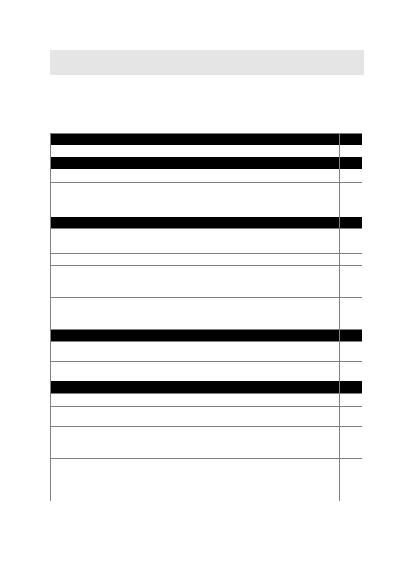
4.5 Post-Installation Checklist
INSTALLATION LOCATION YES NO
Have you verified the unit and vent termination meet the clearance requirements?
COMBUSTION AIR AND VENTING YES NO
Have all corrosive compounds been removed from around the direct vent furnace?
Are the correct venting products for the installed model being utilized? Have you
completely followed the installation instructions in this manual?
Have you verified the vent system does not exceed the maximum length for the
number of elbows used?
GAS SUPPLY YES NO
Has a manual gas control valve been placed in the gas line to the furnace?
Have you checked the gas lines and connections for leaks?
Have you confirmed that the gas inlet pressure is within limits?
Did you confirm that the furnace is rated for the gas type supplied?
Have you verified the system is functioning correctly by connecting your manometer to
the gas pressure test port on the furnace?
Did you operate all gas appliances in the home or facility at high fire?
Did you verify that the inlet gas pressure at the furnace did not drop below that listed
on the rating plate?
ELECTRICITY
YES NO
Did you confirm that the electricity is supplied from a 120 VAC, 60 Hz power source, is
in a properly grounded circuit, and turned on?
Have you confirmed that an extension cord or an adapter plug has NOT been used
with the furnace?
FINAL ITEMS
YES NO
Did you install the front panel?
Have you explained to the customer the importance of not blocking the vent
termination?
Have you explained to the customer the operation of the furnace, safety guidelines,
maintenance, and warranty?
Did you leave the manual with the customer?
Does the installation conform with local codes or, in the absence of local codes, with
the National Fuel Gas Code, ANSI Z223.1/NFPA 54, or the Natural Gas and Propane
Installation Code, CSA B149.1? If installed in a manufactured home, the installation
must conform with the Manufactured Home Construction and Safety Standard, Title 24
CFR, Part 3280 and/or CAN/SCA Z240 MH Series, Mobile Homes.
Complete the following checklist when installation is complete. You should be able to answer YES to
each question. If you answer NO to any question, installation is not complete. Refer to the applicable
section in this manual for additional information. For assistance, contact your local dealer or
distributor, or call Rinnai Customer Care at 1-800-621-9419.
EX38DT Installation and Operation Manual 29
5. Operation
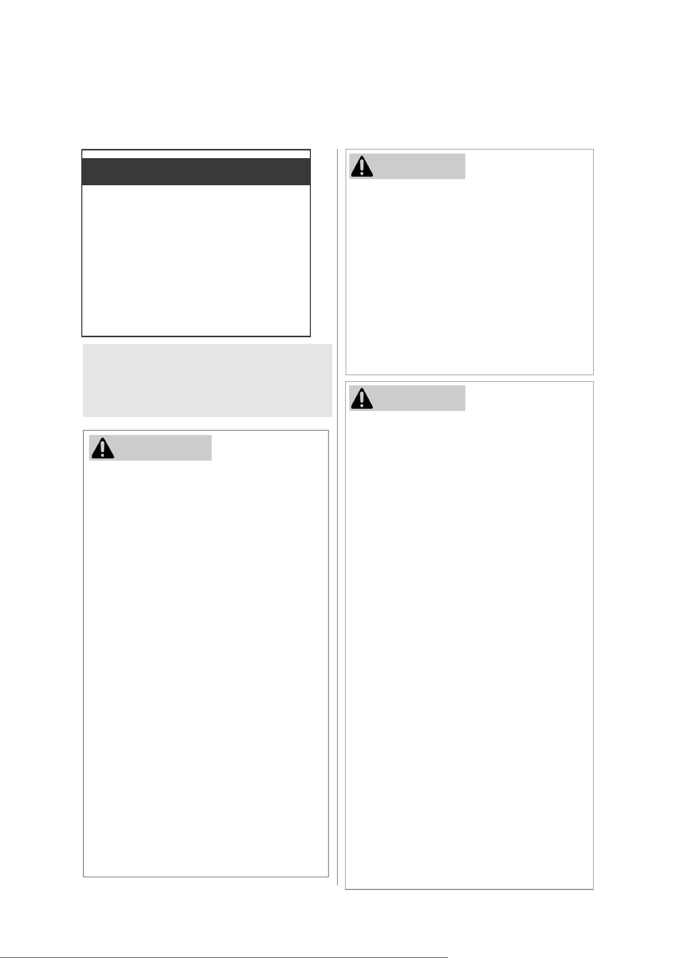
5.1 Safety
Precautions
—Iftheinformaoninthese
instruconsisnotfollowedexactly,
afireorexplosionmayresult
causingpropertydamage,personal
injuryordeath.
— Donotstoreorusegasolineorother
flammablevaporsandliquidsinthe
vicinityofthisoranyother
appliance.
— WHATTODOIFYOUSMELLGAS
Donottrytolightanyappliance.
Donottouchanyelectrical
switch;donotuseanyphonein
yourbuilding.
Immediatelycallyourgas
supplierfromaneighbor’s
phone.Followthegassupplier’s
instrucons.
Ifyoucannotreachyourgas
supplier,callthefire
department.
— Installaonandservicemustbe
performedbyalicensed
professional.
WARNING
Keep the area around the furnace clear
and free from combustible materials,
gasoline, and other flammable vapors
and liquids.
Do not use this furnace if any part has
been under water. Immediately call a
trained and qualified professional to
inspect the furnace and to replace any
part of the control system and any gas
control which has been under water.
Do not operate furnace with the panels
removed, cracked or broken.
WARNING
Do not block the warm air discharge. Do
not allow anyone to sleep directly in front of
the furnace.
Children and adults should be alerted to
the hazards of high surface temperature
and should stay away to avoid burns or
clothing ignition.
Young children should be carefully
supervised when they are in the same
room as the furnace.
Clothing or other flammable material
should not be placed on or near the
furnace.
Any safety screen or guard removed for
servicing must be replaced prior to
operating the furnace.
Do not insert items into the louvers.
Do not spray aerosols near the furnace
while it is operating. Most aerosols contain
butane gas which is flammable.
Do not unplug the furnace while it is
operating or while the fans are on.
Do not use bare hands to touch the front
louvers due to high temperatures which
may cause burns.
Wear hand protection when touching the
side back covers, front louver, and rear
intake for the convection fan.
Prevent dust from accumulating on the
power cord, side covers, and parts behind
the furnace.
Do not sit on the furnace.
Do not place containers of liquid on top of
the furnace. Water spillage can cause
extensive damage to the furnace and may
result in electric shock.
CAUTION
Topics in this section
Safety Precautions
Operating Instructions
Control Panel
Basic Operation Settings
Add Water to the Humidifier
Adjust Air Flow Direction
Restart Function
Diagnostic Codes
30 EX38DT Installation and Operation Manual
FOR YOUR SAFETY READ BEFORE OPERATING
WARNING
If you do not follow these instructions exactly, a fire or explosion
may result causing property damage, personal injury or loss of life.
A. This appliance does not have a pilot. It is equipped
with an ignition device which automatically lights the
burner. Do not try to light the burner by hand.
B. BEFORE OPERATING smell all around the
appliance area for gas. Be sure to smell next to the
floor because some gas is heavier than air and will
settle on the floor.
WHAT TO DO IF YOU SMELL GAS:
Do not try to light any appliance.
Do not touch any electric switch; do not use any
phone in your building.
Immediately call your gas supplier from a
neighbor’s phone. Follow the gas supplier’s
instructions.
If you cannot reach your gas supplier, call the fire
department.
C. Use only your hand to push in or turn the gas
control knob. Never use tools. If the knob will not
push in or turn by hand, do not try to repair it, call a
qualified service technician. Force or attempted
repair may result in a fire or explosion.
D. Do not use this appliance if any part has been
under water. Immediately call a qualified service
technician to inspect the appliance and to replace
any part of the control system and any gas control
which has been under water.
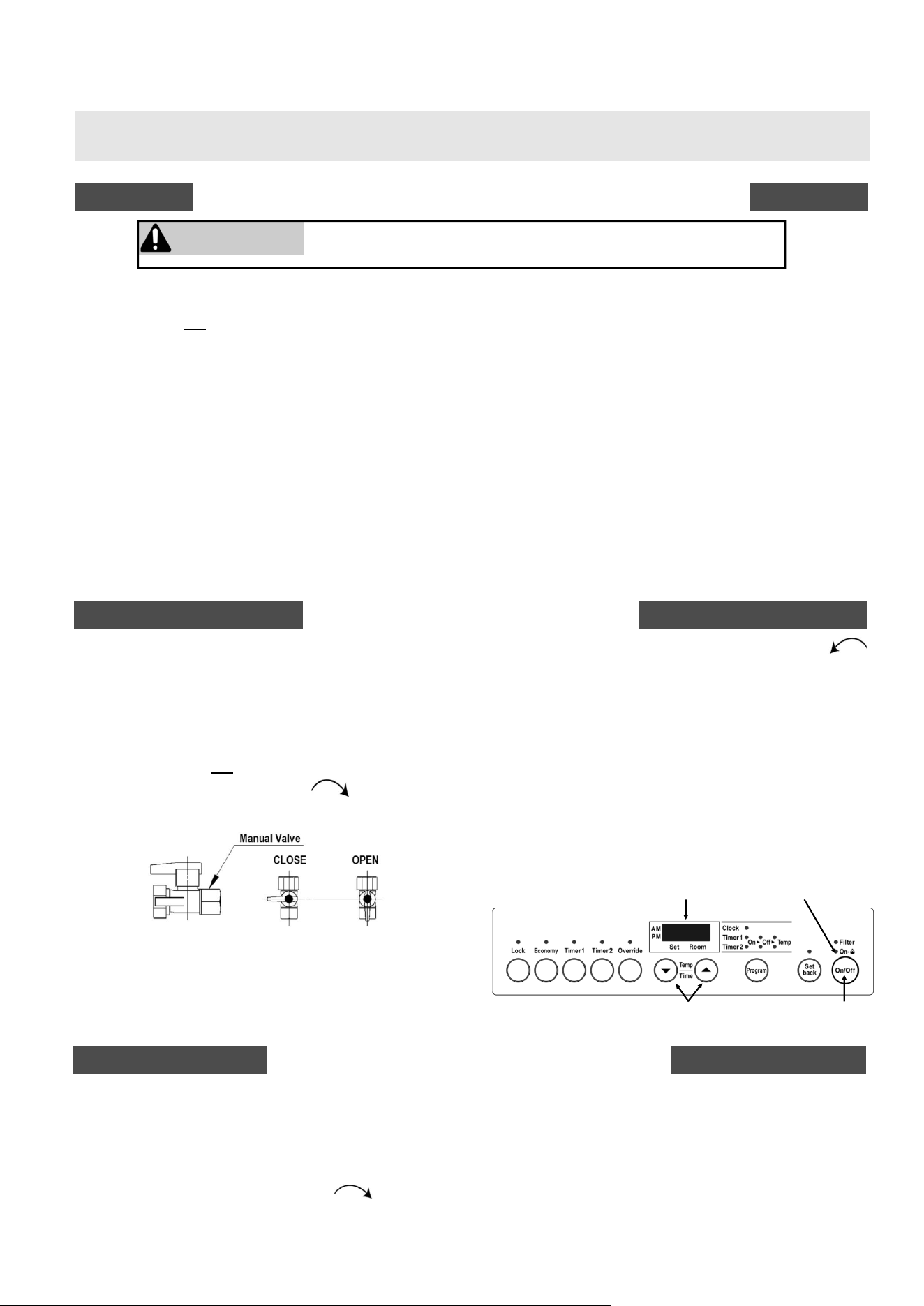
OPERATING INSTRUCTIONS
TO TURN OFF GAS TO APPLIANCE
5.2 Operating Instructions
1. STOP! Read the safety information above.
2. Set the thermostat to lowest setting.
3. Turn off all electric power to the appliance using the
ON/OFF button on the control panel.
4. This appliance does not have a pilot. It is equipped
with an ignition device which automatically lights
the burner. Do not try to light the burner by hand.
5. Turn Manual valve clockwise to the full OFF
position.
6. Wait five (5) minutes to clear out any gas. Then
smell for gas, including near the floor. If you smell
gas, STOP ! Follow “B” in the safety information
above. If you don’t smell gas go to the next step.
7. Turn the manual gas valve counterclockwise
to the full ON position.
8. Turn on all electric power to the appliance using the
ON/OFF button.
9. Set the thermostat to desired setting.
10. Burner is lit when indicator lamp “ON” turns red.
11. “ON” indicator is lit and fault code 11 flashes when
burner fails to ignite.
12. If the appliance will not operate, follow the
instructions “To Turn Off Gas To Appliance” and
call your service technician or gas supplier. See
manual for additional information.
1. Set the thermostat to lowest setting.
2. Turn off all electric power to the appliance if service
is to be performed (Using the ON/OFF button
located on control panel.)
3. Locate the manual gas valve.
4. Turn the manual valve clockwise to the full
OFF position.
NOTE: The fan will continue to operate until the
appliance is cool. Do not turn the appliance off by
unplugging it from the wall. Keep burner and control
compartment clean. See installation and operating
instructions.
Display
ON Indicator
ON/OFF
Button
Up/Down
Buttons
EX38DT Installation and Operation Manual 31
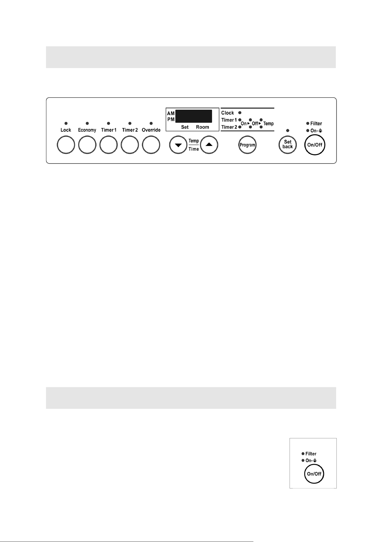
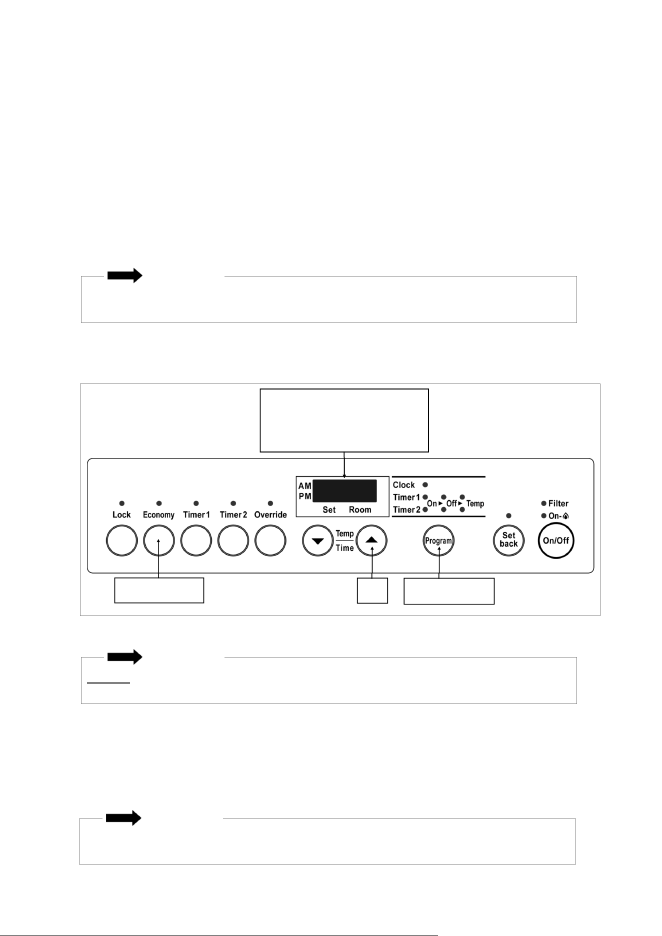
The direct vent furnace includes a controller integrated into the front cover. Each feature on the
control panel is described in the following sections.
5.3 Control Panel
Sensible Temperature Control
The sensible temperature control feature allows comfortable heating which matches the conditions in
the room.
Based on the information collected by the room temperature thermistor when the heating starts, the
heating capacity is automatically adjusted to achieve a comfortable heating effect and to reach the
temperature setting quickly.
Occasionally, the room temperature may briefly exceed the temperature setting due to the layout of
the room or heating area.
After the furnace is turned on and begins operating, the display will dim. The display will turn off
when the furnace is turned off. While programming the timers the display will turn off several sec-
onds after a button is last pushed.
Display
Note: The factory default is °F.
1. The furnace must be turned off.
2. Press the Timer 1 and Timer 2 button at the same time for about 5 seconds. The display will
show “ºC” or “ºF”.
3. Use the arrow keys to select the temperature scale.
4. Press the ON/OFF button.
Fahrenheit or Celsius
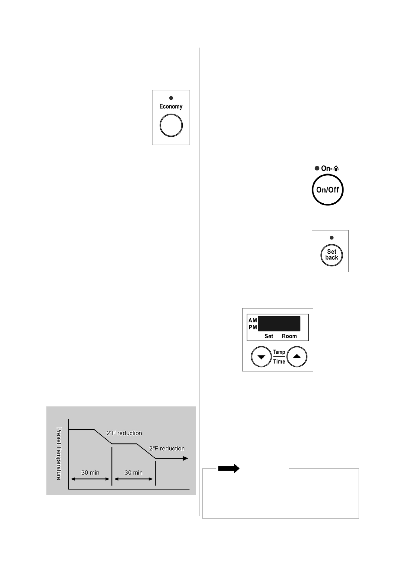
Press the ON/OFF button to operate the furnace. The ON indicator will glow green.
Once the burner ignites the ON indicator will glow red. When the furnace warms
up, the fan will automatically start.
To turn the furnace off, press the ON/OFF button. The ON indicator light will go
out. The fan will continue to operate for several minutes after the burner has gone
out in order to cool the furnace. Do not unplug the furnace while the fan is running.
5.4 Basic Operation Settings
5.4.1 On/O
Figure 35: Control Panel
Figure 36
32 EX38DT Installation and Operation Manual
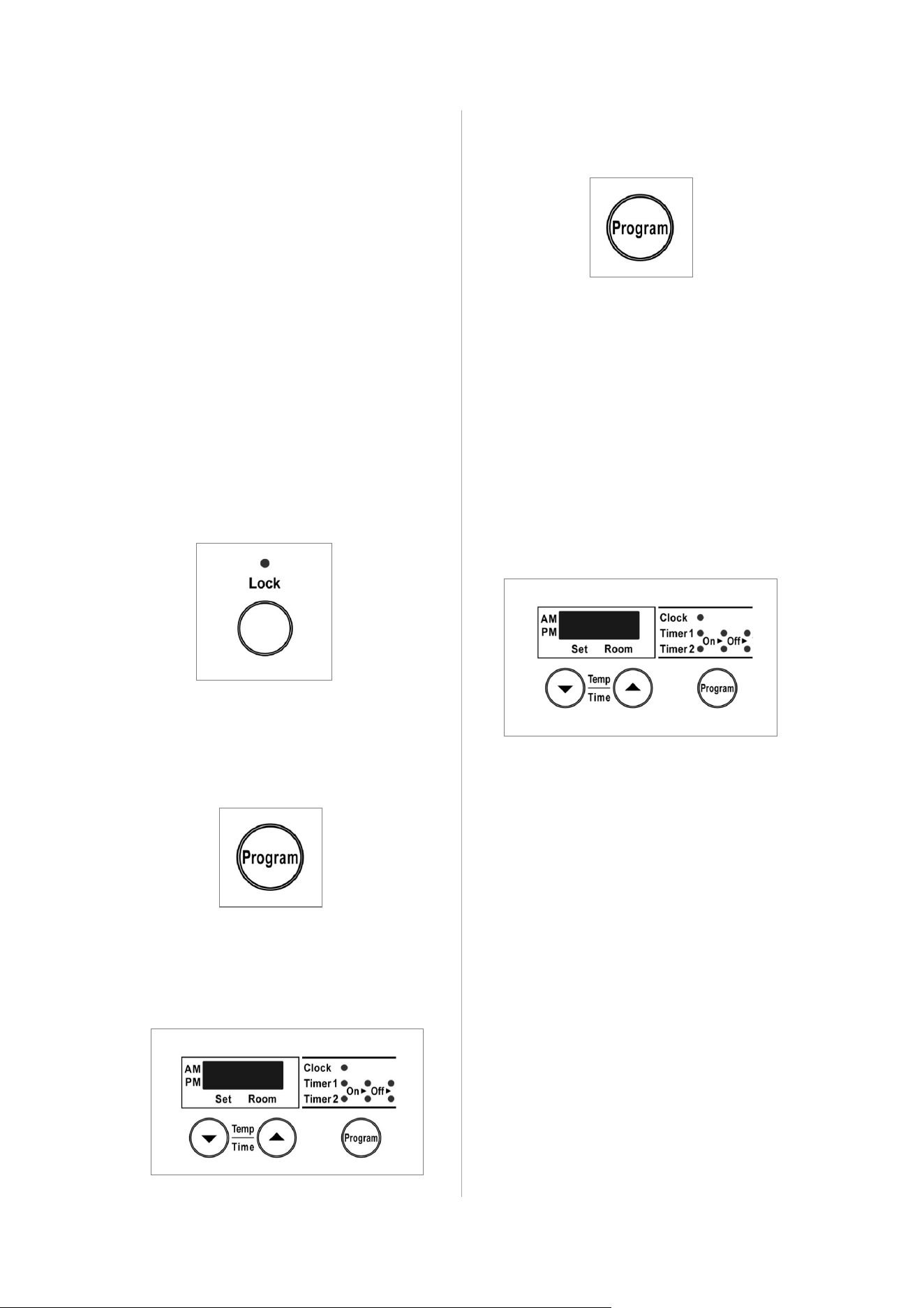
The Lock feature will help to prevent accidental
operation of the furnace and to prevent
children from operating the furnace.
To activate Lock, press the Lock button. The
indicator will light and a beep will sound.
To deactivate Lock, press the Lock button and
hold for about 2 seconds. The indicator light
will go out and a beep will sound.
The lock can be activated when the
furnace is ON or OFF.
If activated while the furnace is ON, all
controls other than the OFF switch will be
locked.
If activated while the furnace is OFF, then
all controls will be locked.
If the furnace is turned off while the Lock is
activated, it cannot be turned on again until
the lock is deactivated.
Deactivating the lock releases the control
buttons.
1. Press the “Program” button.
2. The light next to “Clock” should be flashing.
Press the up and down arrows to set the
time. Holding down either of the arrow keys
will change the time more quickly.
3. Press the “Program” button until none of
the time options are flashing.
1. Turn the furnace on by pressing the “ON/
OFF” button.
2. Press the up or down arrows to set the
temperature. The left side of the display
shows the temperature setting. The right
side of the display shows the room
temperature.
5.4.2 Lock
5.4.4 Operate the Furnace
Manually
5.4.3 Set the Clock
Figure 38
Figure 37
Figure 40
Figure 39
Figure 41
The thermostat automatically modulates the
burner and the fan to maintain the
temperature setting.
The temperature settings available are:
L - burner is on minimum combustion
60-80ºF (16-26°C) in 2ºF (1°C)
Increments
H - burner is on maximum combustion
EX38DT Installation and Operation Manual 33
ECONOMY
UP
PROGRAM
00 - Default Factory Setting
01 - Remote Thermostat Mode
02 - Control Panel Mode
The following buttons/indicators on the control panel will remain functional in either mode:
ON/OFF Button
FILTER Indicator
ON Indicator
DISPLAY (The DISPLAY will be blank except in the event of an error code. All error codes will
show on the DISPLAY in either mode. Error codes will not show on the remote thermostat even
when in remote thermostat mode.)
A remote thermostat can be installed for the furnace with the Remote Thermostat Installation Kit
(Part # 204000045 for US installations, Part # 204000048 for Canadian installations). Once
installed, the furnace must be placed in Remote Thermostat mode by following the steps below:
1. Ensure the furnace is plugged in but is turned OFF.
2. Ensure the Set back feature is turned OFF.
3. Press and hold the Economy + Up + Program buttons for 2.5 seconds and then release (00
appears in the display).
4. Press the UP button (01 appears in the display).
5. Press the ON/OFF button; the display will go blank. The furnace is now in Remote Thermostat
mode.
Do not unplug the furnace within two hours of entering Remote Thermostat mode. This will cause
the furnace to revert back to the Default Factory Setting.
Note: To return the furnace back to Control Panel mode, repeat steps 1-3. At step 4, press the UP
button until 02 appears in the display. Next, press the ON/OFF button; the display will go blank. The
furnace is now in Control Panel mode.
5.4.5 Remote Thermostat Mode (Optional Accessory)
IMPORTANT
The remote thermostat will NOT control the furnace’s ability to power on or power down. This
must still be done by using the ON/OFF button of the furnace.
IMPORTANT
DO NOT place furnace into 01 (Remote Thermostat Mode) without wall thermostat connection
components. Failure to do so may cause improper operation of the unit.
IMPORTANT
Figure 42
34 EX38DT Installation and Operation Manual
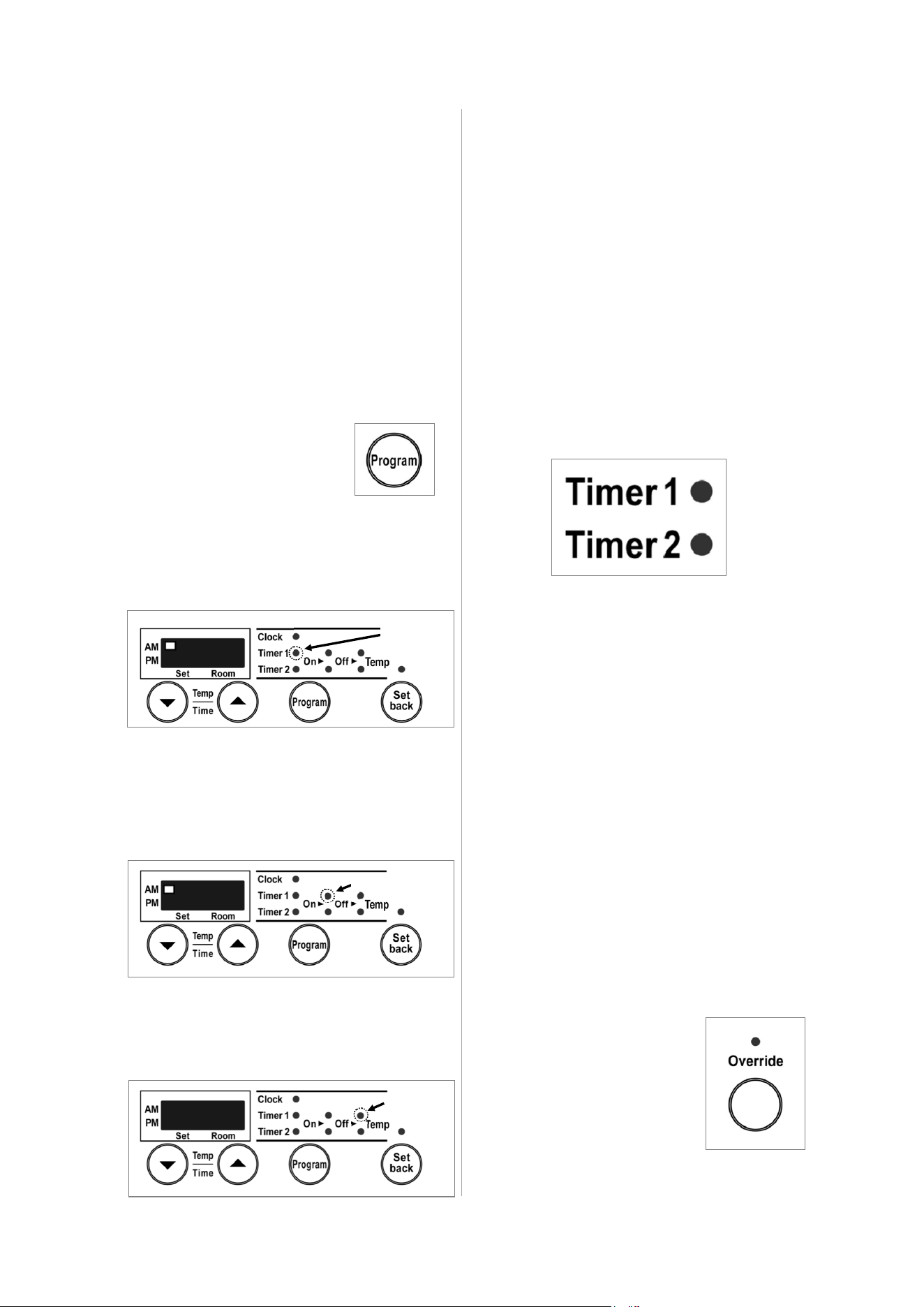
This function is used only when the furnace is
in Timer operation.
It allows you to “override” the reset timer
setting until the beginning of the next Timer
period.
For example, if the furnace is ON, pressing
the “Override” button will turn the furnace OFF
until the next period. If the furnace is OFF,
pressing the “Override” button will turn the
furnace ON, and allow you to select a
temperature setting, until the next period. The
furnace will remain on until the next timer
period or until the Override function is turned
off.
5.4.7 Override Function
5.4.6 Setting and Operating
the Timers
Figure 48
Confirm the clock is correct.
NOTE: The clock will have to be reset in case
of a power failure. However the timers will retain
their settings.
The furnace will start before the programmed
starting time in order to heat the room by the
programmed starting time.
The timers can be set while the furnace is on or
off. To operate the timer, the furnace must be
on.
Setting the timers:
2. The light next to “Timer 1 on” should be
flashing. Press the up or down arrows to set
the start time. Holding down either of the
arrow keys will change the time more quickly.
Operating the timers:
To operate the furnace using a Timer, press
the ON/OFF button and the appropriate Timer
button. The furnace will operate from the start
to end times you have entered for that Timer. It
will operate at the temperature setting that has
been set for the furnace. The timer can be set
while the furnace is operating.
Figure 43
While in standby, the timer LED will be on with
a solid light. When operating the LED will be
flashing.
Figure 47
4. Press the “Program” button again so that the
Timer 1 Temp Position is flashing. Press the
up or down arrows to set the temperature.
Figure 44
3. Press the “Program” button again so that
the Timer 1 off position is flashing. Press
the up or down arrows to set the end time.
Holding down either of the arrow keys will
change the time more quickly.
Figure 45
1. Press the “Program”
button twice to set Timer 1.
5. Press the “Program” button again to
set the times for Timer 2. Follow the
same steps above to set the start and
end times.
6. Press the “Program” button until none
of the time options are flashing up.
9:00
6:00
72
Flashing
Flashing
Flashing
When in override function,
pressing the “Override” button
will return the furnace to the
operation of the current timer
period.
Figure 46
EX38DT Installation and Operation Manual 35
The Set Back feature is intended to prevent
the installation location from falling below a
specified temperature. It is not intended as an
alternate thermostat, but rather a preventative
measure against freezing.
The Economy mode can only be
set while the furnace is
operating (heating). Once it is
set, it will remain in the system
memory until deactivated.
1. To turn the Economy mode
on, press the “Economy”
button. The Economy
indicator is lit.
This function allows a minimum room
temperature to be pre-set, between 38ºF and
78ºF (in 1ºF increments) This temperature
should be set below the room temperature
setting. The default setting is 60ºF. Once the Set
back function is selected the furnace will start
heating whenever the room temperature falls
below the selected temperature, regardless of
timer or manual settings.
Follow these steps to set and operate the Set
back feature:
1. Make sure the furnace is
turned OFF.
2. Press the “Set back” button.
The light above the button will
come on.
3. Press the up and down buttons to set the
minimum temperature.
When the “Set back” indicator is on, frost
protection is operating, and will always prevent the
room temperature from falling below the pre-set
minimum temperature (as long as electric power
and gas is supplied).
To turn this feature off, press the “Set back” button.
The unit will retain its ON or OFF setting after a
power failure. (Default setting at the factory is on.)
5.4.9 Set Back
5.4.8 Economy (Energy
Saving Mode)
IMPORTANT
Figure 50: Economy Mode
Figure 53
Figure 51
Figure 49
The Economy mode now remains in the
system memory.
If the furnace is turned off manually, or
stops heating as a result of an OFF timer
period, the “Economy “ indicator will go
out.
Whenever the furnace starts heating
again, the “Economy” indicator will light.
2. To turn the Economy mode off, press the
“Economy” button. The “Economy “
indicator will go out.
The Economy mode can only be turned
off while the furnace is operating
(heating) and when the “Economy”
indicator is lit.
Economy Mode Information
After the room is heated initially, the air
temperature may be dropped to a lower level
without affecting comfort. The Economy Mode
reduces the temperature by 2 ºF, 30 minutes
after the room temperature setting is reached.
After another 30 minutes, it reduces the
temperature setting by another 2 ºF, effectively
saving energy. The room temperature setting
will drop up to a total of 4 ºF.
The Economy Mode will not operate if the
furnace is under capacity for the room size.
Figure 52
36 EX38DT Installation and Operation Manual
If there is a power failure while the furnace is
on, then the furnace will start automatically
when the power is restored.
If the furnace fails to ignite, the furnace will
attempt ignition after 1 hour. The “Ignition
Failure” fault code, 11, will appear during that
hour and disappears after a successful ignition.
If ignition fails again, then the fault code will
remain and another attempt to ignite will occur
in 1 hour. The fault code is not stored in the
fault code history.
If the flame is extinguished during forced
combustion then the furnace will attempt
ignition after 1 hour. The “Ignition Failure” fault
code, 11, will appear during that hour and
disappears after a successful ignition. Forced
combustion takes place for about 40-80
seconds after ignition. After this time, the
temperature control logic controls the
combustion.
If the flame is extinguished (burner combustion
failure) while the temperature control logic is
operating the furnace, then the furnace will
immediately attempt ignition. No fault code will
appear.
In summary, if the ignition fails or the flame is
extinguished during forced combustion then the
furnace will attempt to restart after 1 hour. If the
flame is extinguished after this period then the
furnace will immediately attempt ignition.
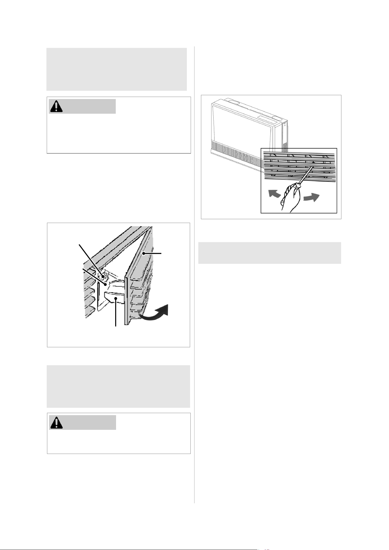
The vertical louvers may be adjusted to move
the air flow more to the right or to the left.
Use a screw driver or similar object to bend
each louver to the desired position.
To fill the tray, open the door as shown in the
illustration and pour water into the tray up to the
Max Fill Line using the spout built into the door.
The air will be humidified as it passes over the
water in the tray.
During operation a small amount of
condensation is produced in the flue system
and drains into the humidifier tray.
5.6 Adjust Air Flow
Direction
5.5 Add Water to
the Humidifier
5.7 Restart Function
Do not fill the tray while the furnace is in
operation. Close the door after filling. The
humidifier tray and surrounding area are hot
when the furnace is on.
CAUTION
Do not adjust the air flow louvers while warm
air is flowing.
CAUTION
Figure 55
Do not bend repeatedly (no more than 5 times)
or else the louver may break.
The horizontal louvers (which determines the
vertical air flow direction) are fixed and cannot
be adjusted.
Figure 54
Max
Fill Line
Access
Door
PULL
Filler Spout: Do not force door open too far.
Close door during operation.
Humidifier
Tray
EX38DT Installation and Operation Manual 37
5.8 Diagnostic Codes
If there is a malfunction the furnace may shut down as a safety precaution and display a fault code to assist in
diagnosing the problem. The fault code will flash in the display on the control panel. When making a service
call, this code will assist with diagnosing the fault.
You may be able to clear the fault code by turning the furnace off and then on again. If the fault code remains
or returns on the next operation, contact Rinnai or your nearest service agent and arrange for a service call.
Table 9: Diagnostic Codes
WARNING
Some of the checks below should be performed by a trained and qualified professional.
Consumers should never attempt any action that they are not qualified to perform.
CODE
DISPLAYED
FAULT REMEDY
11 [3] No Ignition
Check that gas is turned ON.
Check that the vent termination is not blocked.
Refer to section “5.7 Restart Function.”
Service call if repeated.
14 Overheat
Clean filter.
Service call if repeated. [1]
16
Room Overheat
(More than 104°F/40°C)
Lower the room temperature.
30
Overheat Temperature Thermistor 2
Disconnection (open circuit)
31
Room Temperature Thermistor
Disconnection (Open Circuit)
32
Room Temperature Thermistor
Short Circuit
33
Overheat Thermistor 1
Disconnection (Open Circuit)
34
Overheat Thermistor 1
Short Circuit
35
Overheat Temperature Thermistor 2
Short Circuit
40 Pressure Sensor Sensing Tube Failure
49 Pressure Sensor Breakdown
53 Abnormal Spark Sensed
61 Combustion Fan
62 Convection Fan
70 ON/OFF Switch or “Set Back” Switch
71 Solenoid Valve Failure
72 Flame Rod Failure
73 Communication Error
81 Solenoid Valve
99 Flue Block Check around the flue terminal for blockage. [2]
Service Call
[1] If the fusible link needs replacement, it must be done by a qualified service agency. In addition, the
cause of the overheat needs to be determined. The fusible link is a one use safety device that breaks to
shut off the furnace.
[2] Remove any obstructions. The flue needs to be kept clear to expel exhaust gases. If the furnace fails to
operate contact a qualified service agency.
[3] The display of code 11 is dimly flashing.
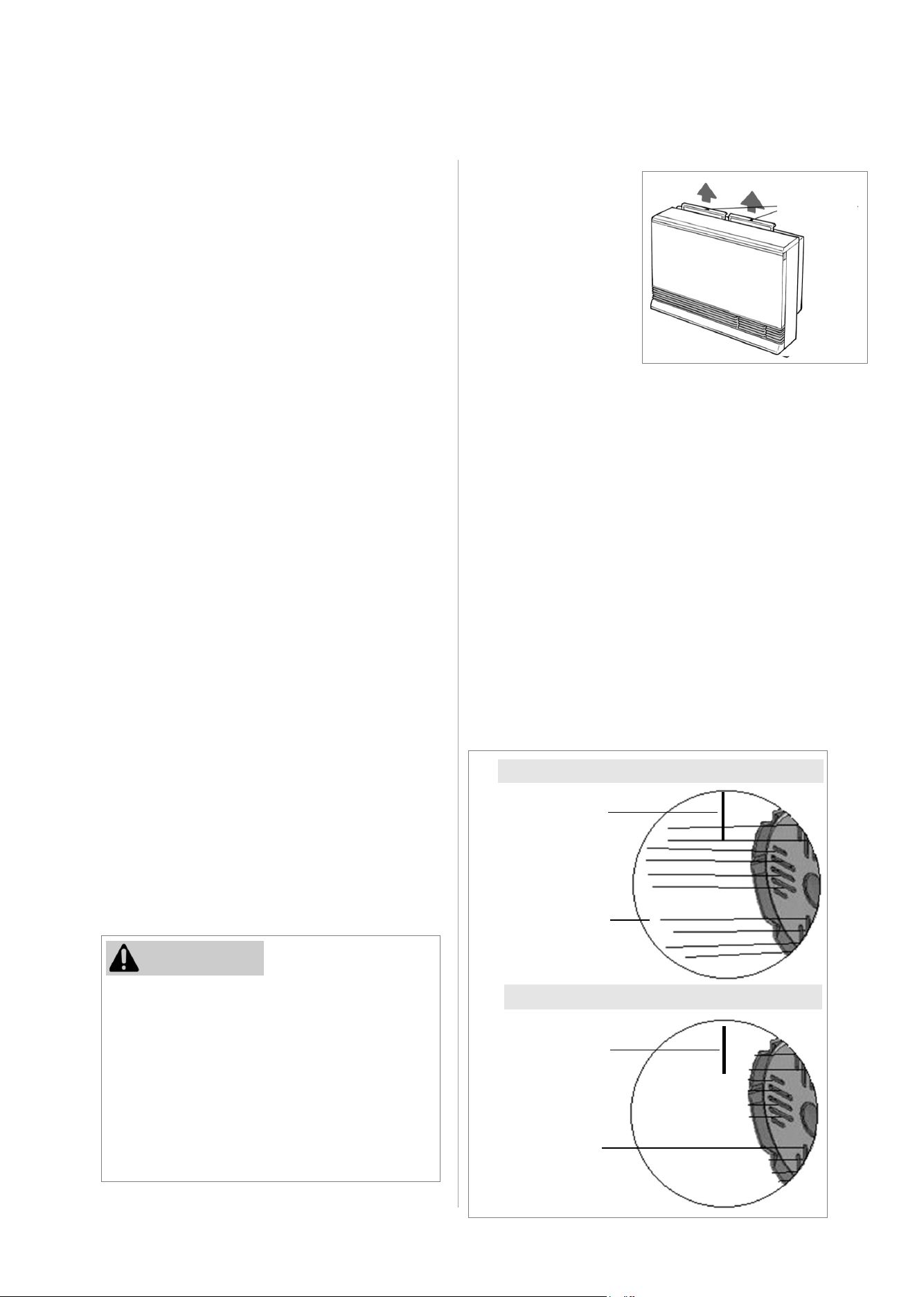
38 EX38DT Installation and Operation Manual
Filters
Dirty filters reduce the
air flow and the
furnace’s ability to
produce heat. The
filters should be
cleaned frequently
during the heating
season.
If the filters become
blocked, the filter
indicator lamp will flash
red and a beep will
sound five times.
Visual Inspection of Flame
Check that the burner flames are operating normally.
The flame can be seen through the circular window.
When operating normally the burner flame should
appear as long, clear, blue, stable, streaks. Yellow
flames or an orange color is abnormal and
maintenance is required.
NORMAL
This direct vent furnace must be inspected
annually by a trained and qualified
professional. Repairs and maintenance must
be performed by a trained and qualified
professional. The trained and qualified
professional must verify proper operation
after servicing.
More frequent cleaning may be required due
to excessive lint from carpeting, bedding
material, etc. It is imperative that control
compartments, burners, and circulating air
passage ways of the furnace be kept clean.
Any screen or guard removed for servicing
the furnace must be replaced prior to
operating the furnace. Clean as follows:
1. Turn heat off. Allow to cool for one hour.
2. Remove the front panel by removing the
five screws.
3. Use pressurized air to remove dust from
the main burner, heat exchanger, and
fan blades.
4. Use a soft, dry cloth to wipe the cabinet.
Do not use wet cloth or spray cleaners on
the burner.
The flue should be inspected annually for
blockages or damage.
Motors are permanently lubricated and do
not need periodic lubrication. Keep fan and
motor free of dust and dirt by cleaning
annually.
Verify proper operation after servicing.
When attaching the front panel, do not clip
or pinch any electric cords to prevent electric
shock.
Exterior Care
Dampen soft cloth with warm water. Wring
water out well and wipe the unit.
Do not use volatile substances such as
benzene or thinners as they may cause
fading of the paint and deformation of the
resin.
Prevent dust from accumulating on the
power cord, side covers, and parts
behind the furnace.
Keep the area around flue terminal free of
snow and ice. The furnace will not
function properly if the intake air or
exhaust is impeded by obstructions.
Refer to “Flue Terminal Clearances” in
section “4.3.2 Clearances.” The
clearance in Ref. A should be maintained
from any snow accumulation.
CAUTION
To clean the filters, the furnace should be OFF and
cool. Remove the filter and clean it using a soft dry
cloth or vacuum. If the filter is greasy wash with warm
soapy water, rinse, and dry completely.
Do not use the furnace without the filters installed.
6. Maintenance
ABNORMAL
Figure 57
Figure 56
Yellow or
orange flames
Flame Rod
Long, clear, blue,
stable flames
Flame Rod
Air Filters
This beeping will repeat every five minutes. Eventually
the furnace will turn off and display fault code 14 on
the control panel display.
EX38DT Installation and Operation Manual 39
Before making a service call, please check the following:
7. Troubleshooting
AT IGNITION:
Heater does not operate. Is the heater plugged in?
Have the fuses or breaker blown at the fuse box / breaker
panel?
Is there a power failure?
Is the air filter blocked?
Is anything blocking the outlet for the hot air?
Is the flue blocked?
Warm air does not flow when the
burner lights.
The fan is started automatically after a short delay. This is
to allow the heat exchanger to warm up, helping to avoid
cold drafts.
Smoke or strange smells are
produced on the first trial light up
after installation.
This is caused by grease or oil and dust on the heat
exchanger and will stop after a short time.
Sharp clicking noises at ignition, or
when unit cuts down on the
thermostat, or goes out.
This is simply expansion noise from the heat exchanger.
DURING COMBUSTION:
Low, rumbling noise when the
thermostat operates.
This is the sound of the solenoid gas valves opening and
closing.
Unit is not heating room. Is the air filter blocked?
Is the set temperature high enough?
Is the warm air outlet blocked by anything?
Are the doors and windows of the room closed?
Was the appliance correctly sized for the space?
Air filter is blocked or the louvers
are blocked or obstructed.
Allow heater to cool, clean air filter or obstruction, operate
again.
Heater will not re-ignite after
overheating.
Even after unit has cooled down, the heater does not
ignite again. Repair is necessary. Contact a qualified/
authorized service provider.
WHEN THE UNIT IS TURNED OFF:
Convection fan continues to run
after turning OFF.
This is to remove the residual heat from the heat
exchanger. The fan will stop when the heater cools down.
Steam is discharged from the flue
terminal.
High efficiency appliances tend to discharge water vapor
on cold days. This is normal.
Unit cuts off without apparent
reason.
Check whether filters are blocked. Dirty filters will cause
the heater to overheat.
OTHER POINTS:
40 EX38DT Installation and Operation Manual
Issue No ON
Indicator
No
Burner
Ignition
Abnormal
Combustion
Loss of
Combustion
Gas
Smell
Noisy
Ignition
Takes too
Long to
Warm
Room
Remedy
Not Plugged in
Plug in
Power Failure
Restart Unit
(Initial
Installation) Air
in Gas Pipe
Purge Air
(Installer)
Gas Filter
Blocked
Service Call
Missed Ignition
Service Call
Flue Terminal
Obstructed
Clear
Obstruction
Flue Manifold
Not Connected
Service Call
Louver
Obstructed
Clear
Obstruction
Air Filter
Blocked
Clean Filter
Gas Escape
Service Call
Lock Set
Cancel Lock
Gas Off at
Meter, Tank, or
Valve
Turn Gas On
ON Timer is set
Cancel “ON”
Timer
Additional Troubleshooting Remedies
Table 10: Troubleshooting Remedies
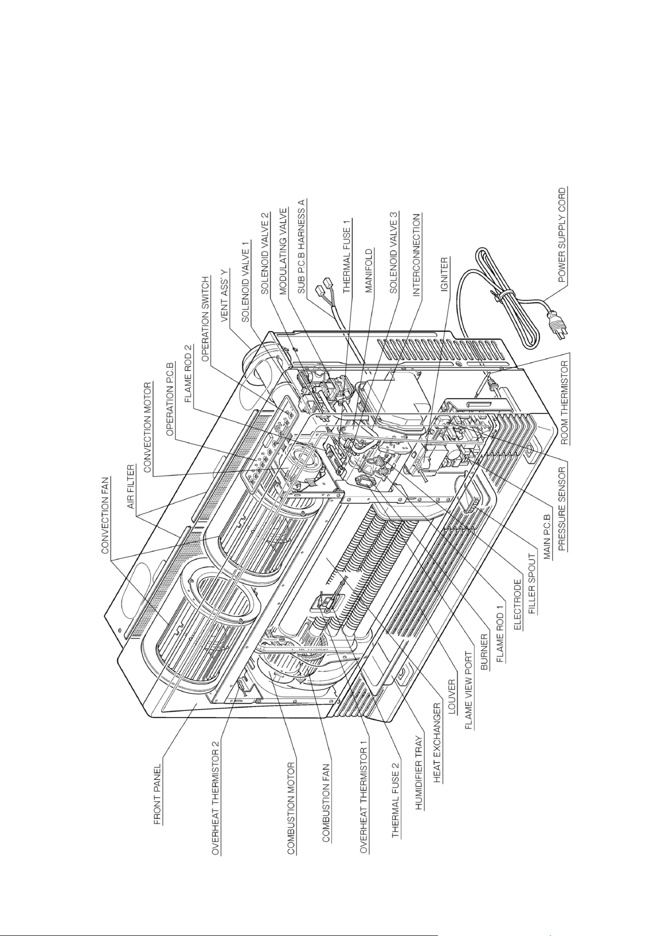
EX38DT Installation and Operation Manual 41
8. Parts
Cut-Away Diagram
Figure 58
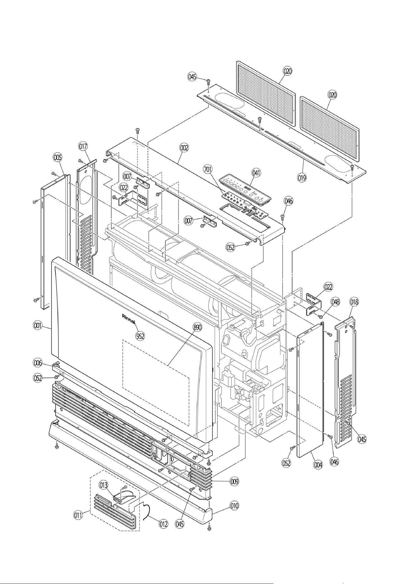
42 EX38DT Installation and Operation Manual
Exploded View of Service Parts
Figure 59
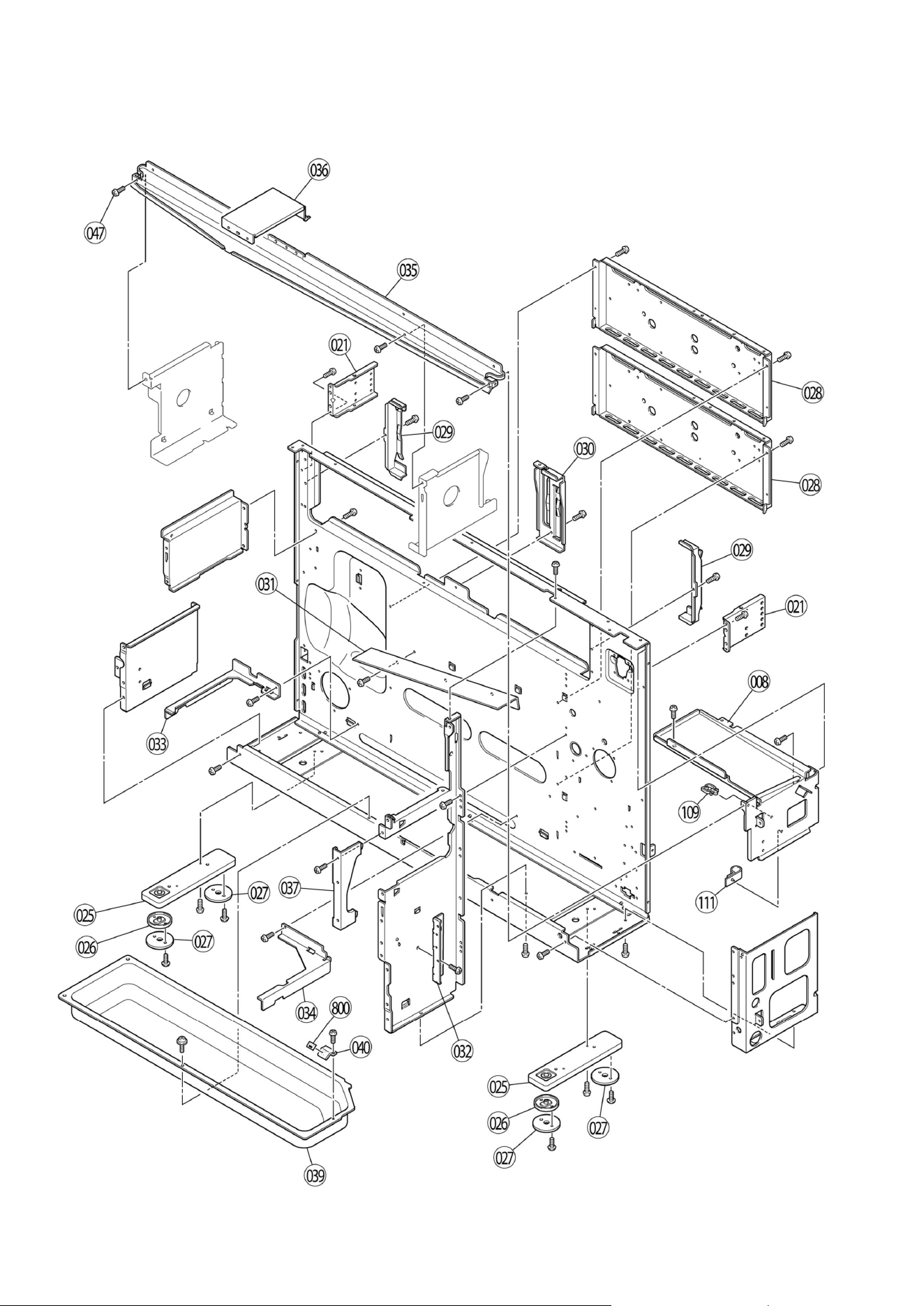
EX38DT Installation and Operation Manual 43
Exploded View of Service Parts
Figure 60
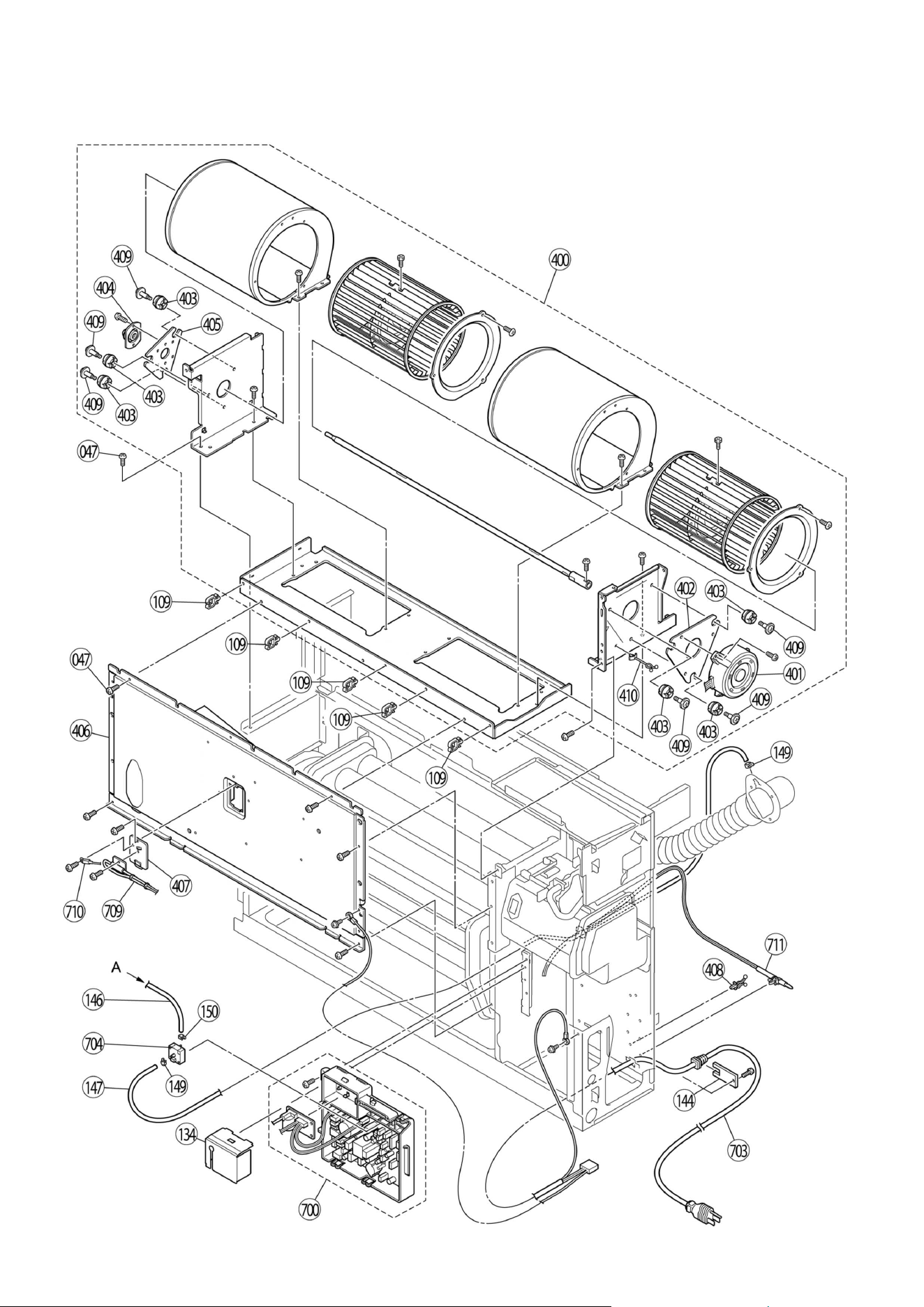
44 EX38DT Installation and Operation Manual
Exploded View of Service Parts
Figure 61
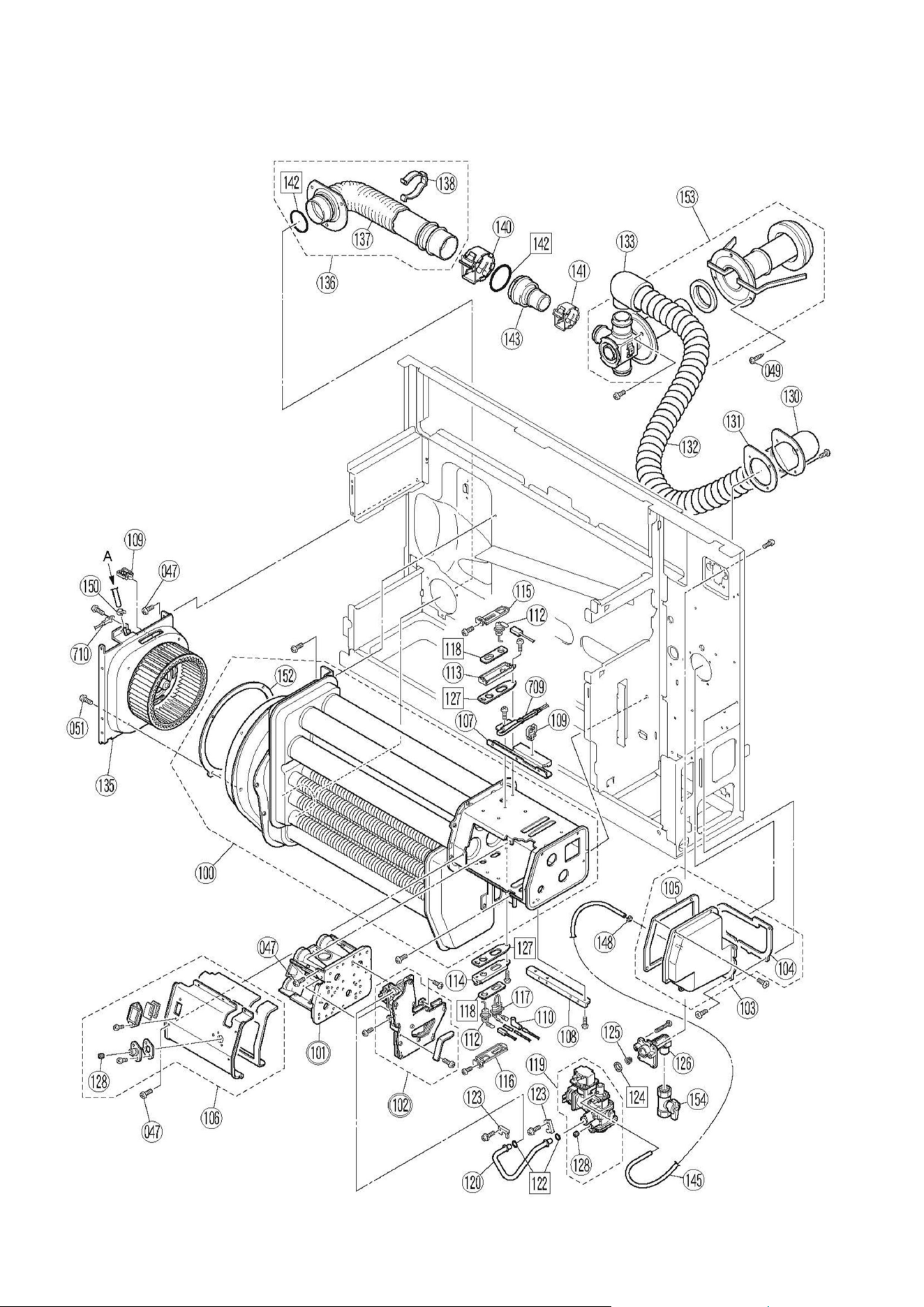
EX38DT Installation and Operation Manual 45
Exploded View of Service Parts
Figure 62
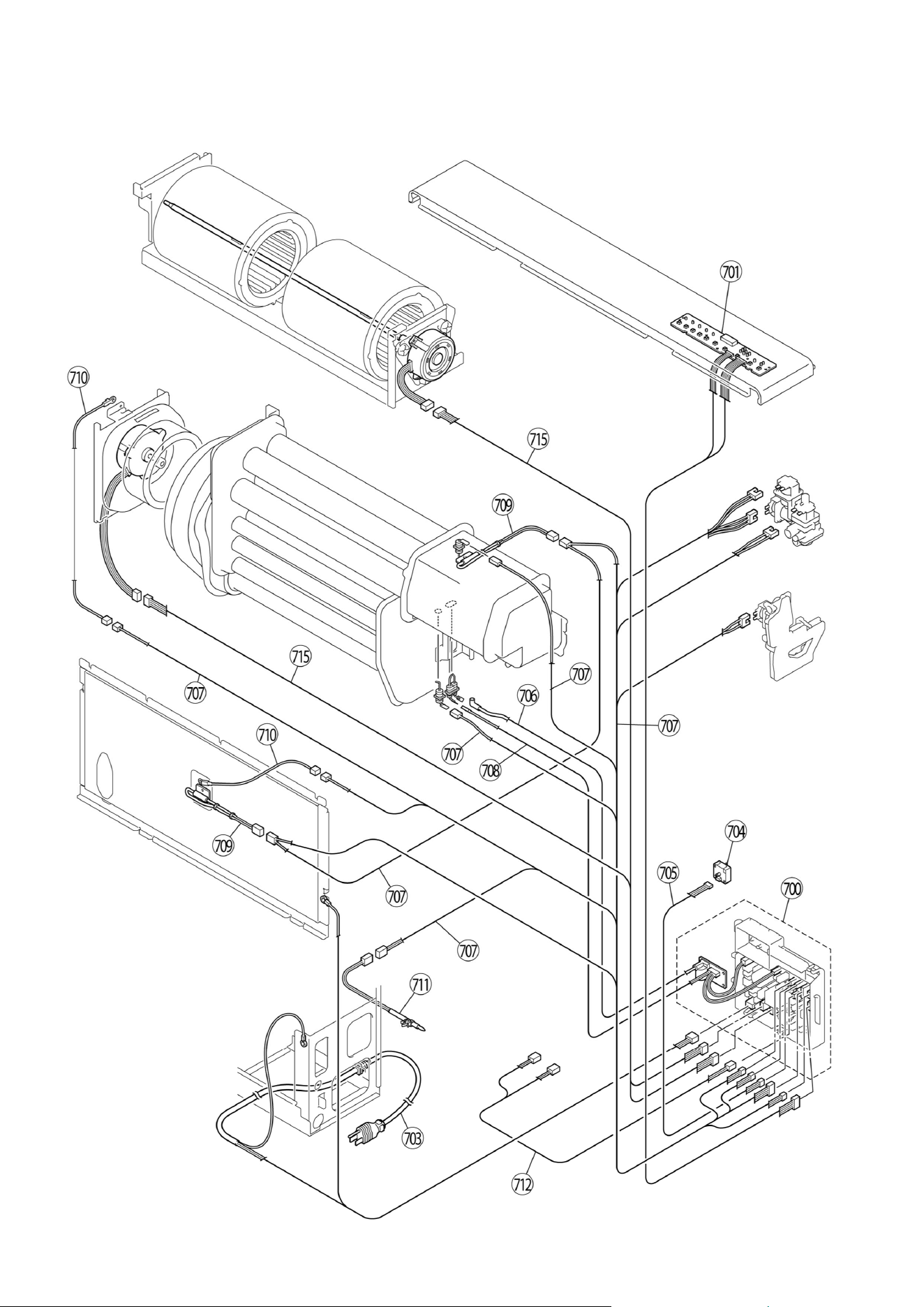
46 EX38DT Installation and Operation Manual
Exploded View of Service Parts
Figure 63
EX38DT Installation and Operation Manual 47
Parts List
NO. NAME PART NUMBER
EX38DT
(Beige)
EX38DT
(White)
001 FRONT PANEL ASSY B 209000140 1
001
FRONT PANEL ASSY A 209000139
1
002
TOP PLATE B 209000142
1
002
TOP PLATE A 209000141
1
004
SIDE PANEL L 209000144
1
004
SIDE PANEL J 209000143
1
005
SIDE PANEL M 209000187
1
005
SIDE PANEL K 209000188
1
006
LOUVER SUPPORT TRIM B 208000051
1
006
LOUVER SUPPORT TRIM C 209000189
1
007
FRONT PANEL HOLDER 209000147
2 2
008
FRAME CORNER UPPER 209000148
1 1
009
LOUVER ASSY B 208000053
1
009
LOUVER ASSY C 209000190
1
010
BOTTOM TRIM ASSY G 209000029
1
010
BOTTOM TRIM ASSY H 209000150
1
011
WATER FILLER TOTAL ASSY B 209000152
1
011
WATER FILLER TOTAL ASSY C 209000191
1
012
WATER FILLER HINGE 209000192
1 1
013
WATER FILLER 209000153
1 1
017
BACK SPACER LEFT G 209000155
1
017
BACK SPACER LEFT J 209000193
1
018
BACK SPACER RIGHT G 209000157
1
018
BACK SPACER RIGHT J 209000194
1
019
BACK SPACER TOP ASSY B 209000159
1
019
BACK SPACER TOP ASSY E 209000195
1
020
AIR FILTER ASSY 208000054
2 2
021
BACK SPACER SUPPORT 1001F‐092X02
2 2
022
WALL BRACKET 209000196
2 2
025
LEG ASSY 209000160
2 2
026
RUBBER BRACKET ASSY 550F‐0220X01
2 2
027
BASE SUPPORT RUBBER 550F‐0225X01
4 4
028
HEAT SHIELD PANEL 209000108
2 2
029
FILTTER SIDE SUPPORT B 209000197
2 2
030
FILTTER CENTER SUPPORT B 209000198
1 1
031
STRAIGHTENING PLATE A 209000163
1 1
032
PCB UNIT MOUNTING ACCESSORY PLATE 209000165
1 1
033
HUMIDIFIER TRAY HOLD PLATE LEFT 208000057
1 1
034
HUMIDIFIER TRAY HOLD PLATE RIGHT 208000058
1 1
035
TOP PLATE SUPPORTER 209000168
1 1
036
TOP PLATE HOLDER 209000169
1 1
037
BURNER BOX SEAL PLATE 206000039
1 1
48 EX38DT Installation and Operation Manual
Parts List (Continued)
NO. NAME PART NUMBER
EX38DT
(Beige)
EX38DT
(White)
039
HUMIDIFIER TRAY 1001F‐037
1 1
040
WATER LEVEL INDICATOR 1001F‐172
1 1
041
CONTROL BOX SP 209000199
1
041 CONTROL BOX SP 209000200 1
045 SCREW 209000201 10 10
046
SCREW 209000202
9 9
047
SCREW 209000203
32 32
048
SCREW 209000204
4 4
049
SCREW 209000205
7 7
051
SCREW 209000206
4 4
052
SCREW 209000207
12 12
100
HEAT EXCHANGER TOTAL ASSY SP 206000040
1 1
101
BURNER TOTAL ASSY (LP) 206000041
1 1
101
BURNER TOTAL ASSY (NG) 206000042
1 1
102
MANIFOLD ASSY A (LP) 206000043
1 1
102
MANIFOLD ASSY B (NG) 206000044
1 1
103
COMBUSTION CHAMBER CONNECTION 206000045
1 1
104
COMBUSTION CHAMBER CONNECTION PACKING A 206000046
1 1
105
COMBUSTION CHAMBEr CONNECTION PACKING B 206000047
1 1
106
BURNER LID ASSY B 206000048
1 1
107
BURNER LID MOUNTING PLATE A 206000049
1 1
108
BURNER LID MOUNTING PLATE B 206000050
1 1
109
WIRE CLIP 205000067
8 8
110
SLEEVE 3022‐0344
1 1
111
CLAMP 209000177
1 1
112
FLAME ROD 205000068
2 2
113
ELECTRODE FIXING PLATE A 205000069
1 1
114
ELECTRODE FIXING PLATE B 205000070
1 1
115
ELECTRODE BRACKET A 205000071
1 1
116
ELECTRODE BRACKET B 205000072
1 1
117
ELECTRODE 205000073
1 1
118
ELECTRODE PACKING 205000074
2 2
119
GAS CONTROL ASSY 206000051
1 1
120
INTER CONNECTION 209000172
1 1
122
O RING M10B‐1‐10
2 2
123
CONNECTING TUBE RETAINER 209000079
2 2
124
PACKING C3I1‐7
1 1
125
GAS FILTER 206000052
1 1
126
GAS INLET 431F‐1110
1 1
127
ELECTRODE PACKING B 205000075
2 2
128
TEST PORT SCREW AU39‐965
1 1
130
AIR INLET D 208000059
1 1
131
AIR INLET PACKING 1004F‐2033
1 1
EX38DT Installation and Operation Manual 49
Parts List (Continued)
NO. NAME PART NUMBER
EX38DT
(Beige)
EX38DT
(White)
132
AIR INTAKE HOSE E RHF1000‐130‐E
1 1
133
AIR INLET ELBOW RHF1000‐132
1 1
134
IGNITER COVER 209000208
1 1
135
COMBUSTION FAN TOTAL ASSY
208000075
1 1
136
EXHAUST ELBOW ASSY 208000065
1 1
137
COVER 1001F‐111X03
1 1
138
ELBOW COVER STOPPER RHF1000‐145
1 1
140
EXHAUST PIPE STOPPER ASSY 1001F‐250
1 1
141
EXHAUST PIPE STOPPER S ASSY 1001F‐1730
1 1
142
O RING 209000173
2 2
143
EXHAUST ADAPTER B ASSY 1004F‐530X01
1 1
144
POWER SUPPLY CORD BRACKET RC‐329‐1033X01
1 1
145
TUBE D 208000017
1 1
146
SENSING TUBE A 205000078
1 1
147
SENSING TUBE J 208000066
1 1
148
Hose Band J 209000085
1 1
149
Hose Band O 209000087
2 2
150
Hose Band N 209000088
2 2
152
LID PACKING 209000209
1 1
153
FLUE ASSY FOT‐151
1 1
154
ON OFF VALVE ASSEMBLY 206000023
1 1
400
CONVECTION FAN TOTAL ASSY 208000067
1 1
401
CONVECTION FAN MOTOR 208000068
1 1
402
MOTOR MOUNTING PLATE 209000210
1 1
403
CUSHION RUBBER 308F‐8273
6 6
404
FAN MOTOR BEARING FC824 908000009
1 1
405
BEARING MOUNTING PLATE 209000211
1 1
406
HEAT SHIELD BOARD ASSY 209000175
1 1
407
OHS BRACKET 209000176
1 1
408
CABLE CLIP CP‐90125‐2
1 1
409
SCREW 209000212
6 6
410
Cable clip 809000183
1 1
700
PC BOARD ASSY 205000097
1 1
701
OPERATION PC BOARD ASSY 205000098
1 1
703
POWER SUPPLY CORD 205000082
1 1
704
PRESSURE SENSOR 208000069
1 1
705
PRESSURE SENSOR HARNESS 205000099
1 1
706
POWER SUPPLY CORD 205000100
1 1
707
SENSOR HARNESS 205000101
1 1
708
IG HARNESS 205000102
1 1
709
TF HARNESS 205000103
2 2
710
HILIMIT THERMISTOR 205000104
2 2
711
ROOM THERMISTOR 205000105
1 1
50 EX38DT Installation and Operation Manual
Model For Converting to Natural Gas For Converting to Propane
EX38DT (RHFE-1006FTA)
203000011 203000012
Conversion Kits (Optional)
712
DVF SUB PCB HARNESS A 205000092
1 1
715
MOTOR HARNESS 205000106
1 1
800
WATER LEVEL LINE LABEL B 209000213
1 1
888
OPERATION MANUAL 200000088
1 1
890
OPERATION LABEL 209000214
1 1
952
FRONT PANEL EMBLEM 209000215
1
952
FRONT PANEL EMBLEM 209000216
1
NO. NAME PART NUMBER
EX38DT
(Beige)
EX38DT
(White)
Parts List (Continued)

EX38DT Installation and Operation Manual 51
For Gas Models Sold in Massachusetts
NOTICE BEFORE INSTALLATION:
This direct-vent appliance must be installed by a
state qualified or licensed contractor and a
properly trained Rinnai Installer. If you are not
properly trained, you must not install this unit.
IMPORTANT: In the State of Massachusetts
(248 CMR 4.00 and 5.00)
For all side wall horizontally vented gas fueled
equipment installed in every dwelling, building
or structure used in whole or in part for
residential purposes, including those owned or
operated by the Commonwealth and where the
side wall exhaust vent termination is less than
seven (7) feet above finished grade in the area
of the venting, including but not limited to decks
and porches, the following requirements shall
be satisfied:
1. INSTALLATION OF CARBON MONOXIDE
DETECTORS. At the time of installation of
the side wall horizontal vented gas fueled
equipment, the installing plumber or
gasfitter shall observe that a hard wired
carbon monoxide detector with an alarm
and battery back-up is installed on the floor
level where the gas equipment is to be
installed. In addition, the installing plumber
or gasfitter shall observe that a battery
operated or hard wired carbon monoxide
detector with an alarm is installed on each
9. Appendices
9.1 Massachusetts
State Gas
Regulations
additional level of the dwelling, building or
structure served by the side wall horizontal
vented gas fueled equipment. It shall be the
responsibility of the property owner to secure
the services of qualified licensed professionals
for the installation of hard wired carbon
monoxide detectors
a. In the event that the side wall horizontally
vented gas fueled equipment is installed in
a crawl space or an attic, the hard wired
carbon monoxide detector with alarm and
battery back-up may be installed on the
next adjacent floor level.
b. In the event that the requirements of this
subdivision can not be met at the time of
completion of installation, the owner shall
have a period of thirty (30) days to comply
with the above requirements; provided,
however, that during said thirty (30) day
period, a battery operated carbon
monoxide detector with an alarm shall be
installed.
2. APPROVED CARBON MONOXIDE
DETECTORS. Each carbon monoxide
detector as required in accordance with the
above provisions shall comply with NFPA
720 and be ANSI/UL 2034 listed and IAS
certified.
3. SIGNAGE. A metal or plastic identification
plate shall be permanently mounted to the
exterior of the building at a minimum height
of eight (8) feet above grade directly in line
with the exhaust vent terminal for the
horizontally vented gas fueled heating
appliance or equipment. The sign shall
read, in print size no less than one-half (1/2)
inch in size, "GAS VENT DIRECTLY
BELOW. KEEP CLEAR OF ALL
OBSTRUCTIONS".
4. INSPECTION. The state or local gas
inspector of the side wall horizontally vented
gas fueled equipment shall not approve the
installation unless, upon inspection, the
inspector observes carbon monoxide
detectors and signage installed in
accordance with the provisions of 248 CMR
5.08(2)(a)1 through 4.
Topics in this section
Massachusetts State Gas
Regulations
Wiring Diagram
Ladder Diagram
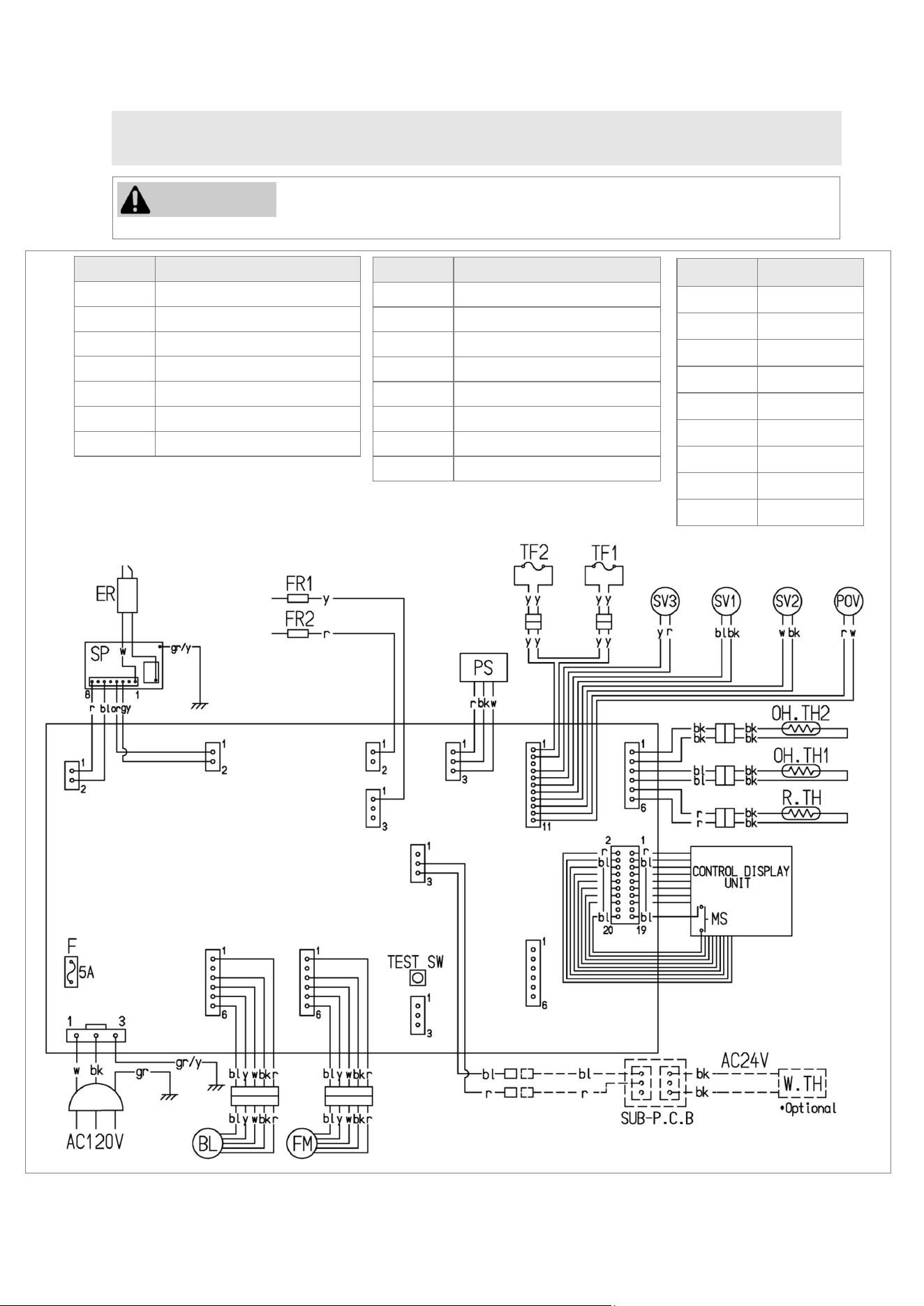
52 EX38DT Installation and Operation Manual
9.2 Wiring Diagram
Label all wires prior to disconnection when servicing controls. Wiring errors
can cause improper and dangerous operation.
CAUTION
Code Color
bk black
bl blue
gr/y green/yellow
r red
gr green
w white
y yellow
gy gray
or orange
Mark Parts Name
MS Main Switch
R.TH Room Thermistor
TF1,2 Thermal Fuse 1, 2
F Fuse
ER Electrode
POV Modulating Solenoid Valve
PS Pressure Sensor
Mark Parts Name
W.TH Wall Thermostat
OH.TH1,2 Over Heat Thermistor 1, 2
FM Convection Fan Motor
SP Sparker
SV1,2 Main Solenoid Valve 1,2
SV3 Solenoid Valve 3
BL Combustion Fan Motor
FR1,2 Flame Rod 1, 2
Figure 64: Wiring Diagram
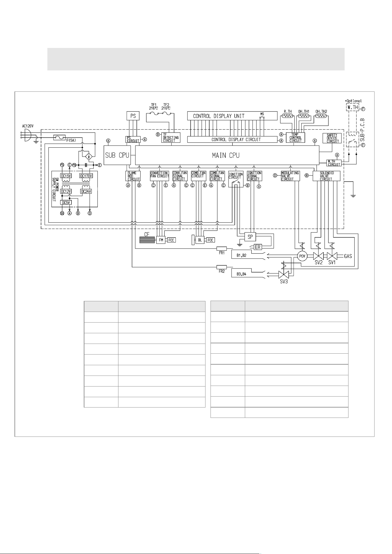
EX38DT Installation and Operation Manual 53
9.3 Ladder Diagram
Figure 65: Ladder Diagram
Mark Parts Name
MS Main Switch
R.TH Room Thermistor
TF1,2 Thermal Fuse 1, 2
F Fuse
ER Electrode
POV Modulating Solenoid Valve
FR1,2 Flame Rod 1, 2
CF Convection Fan
FM Convection Fan Motor
Mark Parts Name
SP Sparker
OH.TH1,2 Over Heat Thermistor 1, 2
SV1~3 Solenoid Valve 1~3
BL Combustion Fan Motor
FCC Fan Control Circuit
B1~4 Burner 1~4
PS Pressure Sensor
W.TH Wall Thermostat
Main CPU Central Processing Unit
Sub CPU Central Processing Unit for Safety
A: DC5V
B: DC12V
C: DC15V
D: DC24V
E: DC170V
F: AC24V
54 EX38DT Installation and Operation Manual
10. Warranty
Models
EX08DT, EX11DT, EX17DT, EX22DT, EX38DT
The Rinnai Standard Limited Warranty covers any defects in materials or workmanship when the
product is installed and operated according to Rinnai written installation instructions, subject to the
terms within this Limited Warranty document. This Limited Warranty applies only to products that are
installed correctly in the United States and Canada. Improper installation may void this Limited
Warranty. It is recommended that a trained and qualified professional who has attended a Rinnai
installation training class complete your installation. This Limited Warranty coverage, as set out in
the table below, extends to the original purchaser and subsequent owners, but only while the product
remains at the site of the original installation, and terminates if the product is moved or reinstalled at
a new location.
What is Covered?
What Will Rinnai Do?
Rinnai will repair or replace the covered product or any part or component that is defective in
materials or workmanship as set forth in the above table. Rinnai will pay reasonable labor charges
associated with the repair or replacement of any such part or component during the term of the labor
warranty period. All repair parts must be genuine Rinnai parts. All repairs or replacements must be
performed by a qualified professional who is properly trained to do the type of repair.
Replacement of the product may only be authorized by Rinnai at its sole discretion. Rinnai does not
authorize any person or company to assume for it any obligation or liability in connection with the
replacement of the product. If Rinnai determines that repair of a product is not possible, Rinnai may
replace the product with a comparable product at Rinnai’s sole discretion. The warranty claim for
product parts and labor may be denied if a component or product returned to Rinnai is found to be
free of defects in material or workmanship; damaged by improper installation, use or operation; or
damaged during return shipping.
Item Period of Coverage (From Date of Purchase)
Heat Exchanger 10 Years
All Other Parts 5 Years
Reasonable Labor 2 Years
How To Obtain Service
For the name of a trained and qualified professional, please contact your place of purchase, visit the
Rinnai website (www.rinnai.us), call Rinnai at 1-800-621-9419 or write to Rinnai at 103 International
Drive, Peachtree City, Georgia 30269.
Proof of purchase is required to obtain warranty service. You may show proof of purchase with a
dated sales receipt, or by registering within 30 days of purchasing the product. To register your
appliance, please visit www.rinnai.us. For those without internet access, please call 1-800-621-
9419. Receipt of registration by Rinnai will constitute proof-of-purchase for this product. However,
registration is not necessary in order to validate this Limited Warranty.

EX38DT Installation and Operation Manual 55
What Is Not Covered?
This Limited Warranty does not cover any failures or operating difficulties due to the following:
Accident, abuse, or misuse
Alteration of the product or any component part
Misapplication of this product
Force majeure
Improper installation (such as but not limited to, condensate damage, improper venting,
Incorrect gas type, or incorrect gas pressure)
Improper conversion (including conversions for inventory adjustment)
Improper maintenance (such as but not limited to vent blockage)
Incorrect sizing
Any other cause not due to defects in materials or workmanship
This Limited Warranty does not apply to any product whose serial number or manufacture date has
been defaced.
Limitation on Warranties
No one is authorized to make any other warranties on behalf of Rinnai America Corporation. Except
as expressly provided herein, there are no other warranties, expressed or implied, including, but not
limited to warranties of merchantability or fitness for a particular purpose, which extend beyond the
description of the warranty herein.
Any implied warranties of merchantability and fitness arising under state law are limited in duration to
the period of coverage provided by this Limited Warranty, unless the period provided by state law is
less. Some states do not allow limitations on how long an implied Limited Warranty lasts, so the
above limitation may not apply to you.
Rinnai shall not be liable for indirect, incidental, special, consequential or other similar damages that
may arise, including lost profits, damage to person or property, loss of use, inconvenience, or liability
arising from improper installation, service or use. Some states do not allow the exclusion or limitation
of incidental or consequential damages, so the above limitation may not apply to you.
This Limited Warranty gives you specific legal rights, and you may also have other rights which vary
from state to state.
www.rinnai.us/warranty

103 International Drive
Peachtree City, GA 30269
Tel: 1-800-621-9419
Web: rinnai.us
rinnai.ca
Rinnai America Corporation
200000082(01)
1/2022
RHF1006-1750(02)