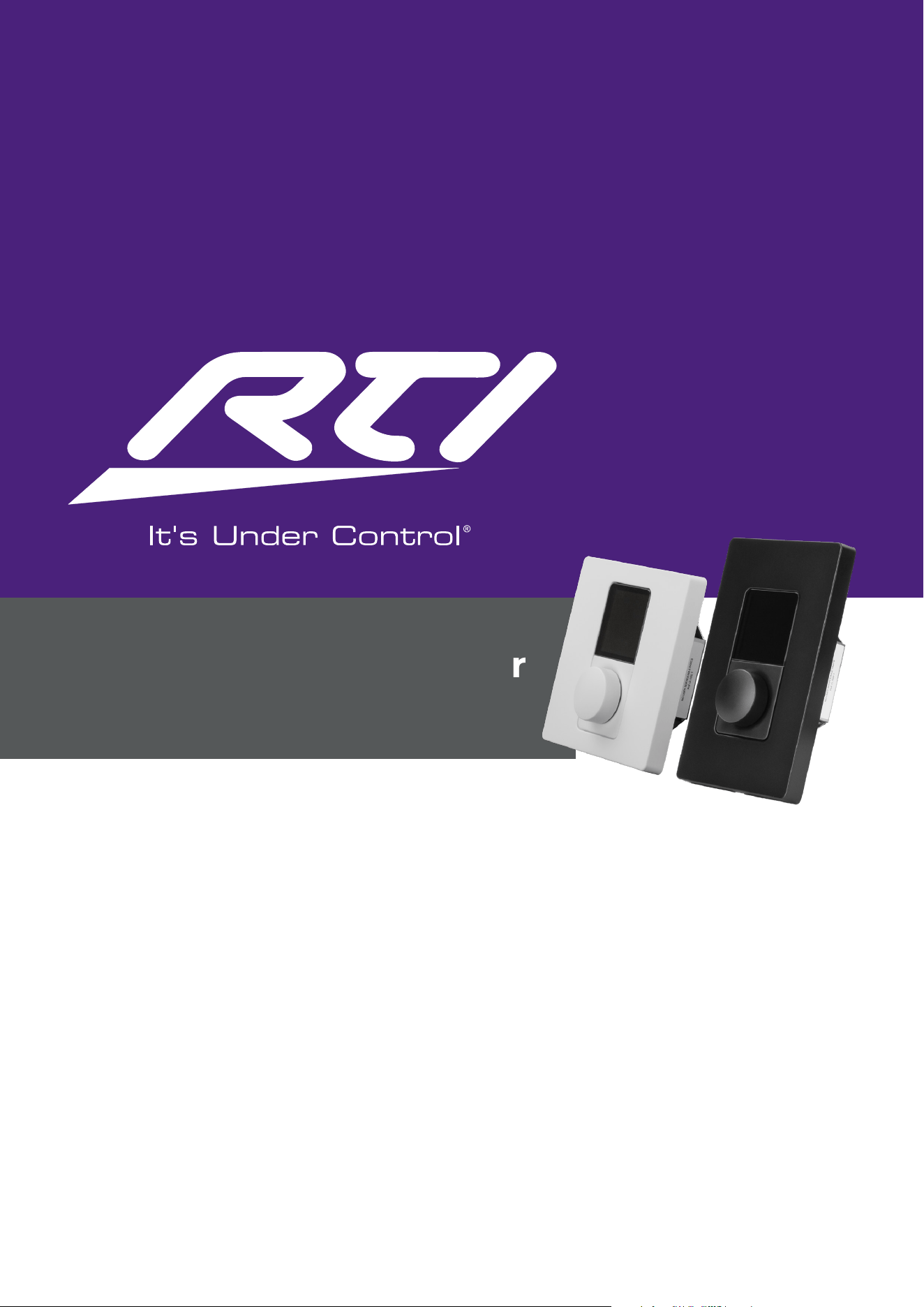
INSTALLATION GUIDE / USER MANUAL
RTI-AMP-IWC-W-EU • RTI-AMP-IWC-W
RTI-AMP-IWC-B-EU • RTI-AMP-IWC-B
RTI-AMP-IWC-W
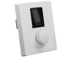
In-Wall Multizone Controller – US, White
RTI-AMP-IWC-W-EU
In-Wall Multizone Controller – EU, White
RTI-AMP-IWC-B
In-Wall Multizone Controller – US, Black
RTI-AMP-IWC-B-EU
In-Wall Multizone Controller – EU, Black
RTI Multizone Controller
User Manual

Technical and Safety Notices
Before installing and using this unit, please read this
guide carefully.
1. Ensure to store this document in a safe place for future
reference.
2. Note this product is intended for installaon by
professional installers only.
3. This document is intended to provide professional
installers with product installaon, conguraon, and
safety guidelines for this product in typical xed-
installaon systems.
4. Please read this document and all safety warnings before
aempng installaon.
5. Please note that this product does NOT include the
in-wall mounng electrical box and installaon screws
required to install the controller.
6. Use a commercially available in-wall mounng electrical
box and installaon screws suitable for the specic wall
material and installaon situaon.
7. All RTI-AMP Series Ampliers Audio products must
be installed in accordance with local, state, federal and
industry regulaons. It is the installer’s responsibility
to ensure installaon is performed in accordance with
all applicable codes, including local building codes and
regulaons. Consult the local authority having jurisdicon
before installing this product.
8. Do not mount the product in locaons where
condensaon may occur.
9. To reduce the risk of re or electrical shock, do NOT
expose this product to rain, liquids or moisture.
10. This product is not intended for installaon or use in
indoor water facility areas (including, without limitaon,
indoor pools, indoor water parks, hot tub rooms, saunas,
steam rooms and indoor skang rinks).
11. Keep the product away from re and heat sources.
12. Do NOT place naked ame sources, such as
lighted candles, on or near the product.
13. Do NOT make unauthorized alteraons to this product.
1/19
This manual is divided into secons covering the following
topics:
• 1. Introducon
• 2. Connecon
• 3. Mounng
• 4. Operaon
• 5. Setup
• 6. Conguraon
• 7. Reset
• 8. Specicaons
Important Safety Instructions
1. Read these instrucons.
2. Keep these instrucons.
3. Heed all warnings.
4. Follow all instrucons.
5. Do not use this apparatus near water.
6. Clean only with a so, dry cloth.
7. Do not install near any heat sources such as
radiators, heat registers, stoves, or other apparatus
(including ampliers) that produce heat.
8. Only use aachments/accessories specied by the
manufacturer.
9. Refer all servicing to qualied service personnel.
Servicing is required when the apparatus has been
damaged in any way, such as power-supply cord or
plug is damaged, liquid has been spilled or objects
have fallen into the apparatus, the apparatus has
been exposed to rain or moisture, does not operate
normally, or has been dropped.
FOR CUSTOMERS IN EUROPE
Informaon to the User
This product complies with the European Direcves
request and the other Commission Regulaons.
Environmental Statement
This product complies with internaonal direcves,
including but not limited to the Restricon of Hazardous
Substances (RoHS) in electrical and electronic equipment,
the Registraon, Evaluaon, Authorizaon and restricon
of Chemicals (REACH) and the disposal of Waste Electrical
and Electronic Equipment (WEEE). Consult your local
waste disposal authority for guidance on how properly to
recycle or dispose of this product.
FOR CUSTOMERS IN THE USA
Informaon to the User
This device complies with part 15 of the FCC Rules.
Operaon is subject to the following two condions:
(1) This device may not cause harmful interference, and
(2) this device must accept any interference received,
including interference that may cause undesired operaon.
This equipment has been tested and found to comply with
the limits for a Class B digital device, pursuant to part 15
of the FCC Rules. These limits are designed to provide
reasonable protecon against harmful interference when
the equipment is operated in a residenal installaon. This
equipment generates, uses, and can radiate radio frequency
energy and, if not installed and used in accordance with
the instrucon manual, may cause harmful interference to
radio communicaons. However, there is no guarantee that
interference will not occur in a parcular installaon.
Changes or modicaons to this equipment not expressly
approved by RTI-AMP Series Ampliers for compliance
could void the user’s authority to operate this equipment.
Informaons a l’ulisateur
CAN ICES-003 (B)/NMB-003(B)
Cet appareil est conforme à la pare 15 de la
réglementaon de la FCC. Son fonconnement repose sur
les deux condions suivantes: (1) cet appareil ne doit pas
provoquer d’interférences et (2) cet appareil doit tolérer
les interférences externes, y compris celles qui peuvent
provoquer un fonconnement anormal.
Ce matériel a fait l’objet de tests prouvant sa conformité
aux limites imposées aux appareils numériques de classe B,
conformément à la pare 15 des réglementaons de la
FCC. Ces limites sont conçues pour fournir une protecon
raisonnable contre les interférences nuisibles lorsque
l’équipement est ulisé dans une installaon résidenelle.
Cet équipement génère, ulise et peut émere de
l’énergie de radiofréquence et, s’il n’est pas installé et
ulisé conformément au manuel d’instrucons, peut causer
des interférences nuisibles aux communicaons radio.
Cependant, il n’y a aucune garane que des interférences
ne se produiront pas dans une installaon parculière.
Toute modicaon non autorisée expressément par RTI-
AMP Series Ampliers Audio est suscepble d’annuler le
droit de l’ulisateur à uliser cet appareil.
2/19
Introduction
Connection
1.1 Device Description
The Mulzone Controller is a wall-mounted device
designed for the remote control of volume level and input
source selecon, of RTI-AMP Series Ampliers.
Each Mulzone Controller can control one zone only. For
example, the remote control of four zones would require
four devices – each assigned to one of the 4 individual
zones.
Mulzone Controller devices can be assigned to the same
zone, although it is not recommended to connect more
than eight (8) Mulzone Controller devices per RTI-AMP
Series Amplier.
1.2 Device Requirements
Mulzone Controller devices are only compable with
RTI-AMP Series Ampliers running rmware version 1.6.0
or later. Ensure to update the rmware installed on the
RTI-AMP Series Amplier before aempng to install and
congure Zone Controller devices. Visit RTI-AMP Series
Amplier support to check and obtain the latest rmware.
Note that the Mulzone Controller is not self-powered.
Power is supplied to the device with the use of a standard
PoE Switch (or PoE injector) and Cat5 cable (or above).
Note that Zone Controllers are not compable with non
network connected RTI ampliers.
Note this product is not compable with ampliers of third
pares – i.e., those not sold under the RTI brand.
1.3 Device Specifications
Input Rating
Connector: RJ45
Cables: Category 5e (or faster STP cables)
PoE Class I device, 48V
Power Consumption
3.84Wmax
Dimensions (H x W x D)
EU: 86,79 x 86,79 x 42,8mm
US: 115,1 x 70,6 x 42,8mm (4,53 x 2,72 x 1,68in)
Weight
EU: 120g / US: 120g (4.2oz.)
Operating Temperature Range
0-40°C (32-104°F)
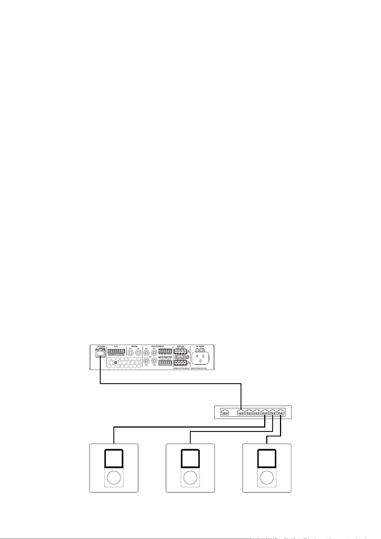
2.1 Device Connection
The illustraon below outlines how to connect mulple
Mulzone Controller devices to RTI-AMP Series Ampliers
using a standard PoE network switch and Cat5 cable.
Unit 2Unit 1 Unit 3
PoE Class1
S/UTP cat.5e Cable
S/UTP cat.5e Cables
3/19
Mounting
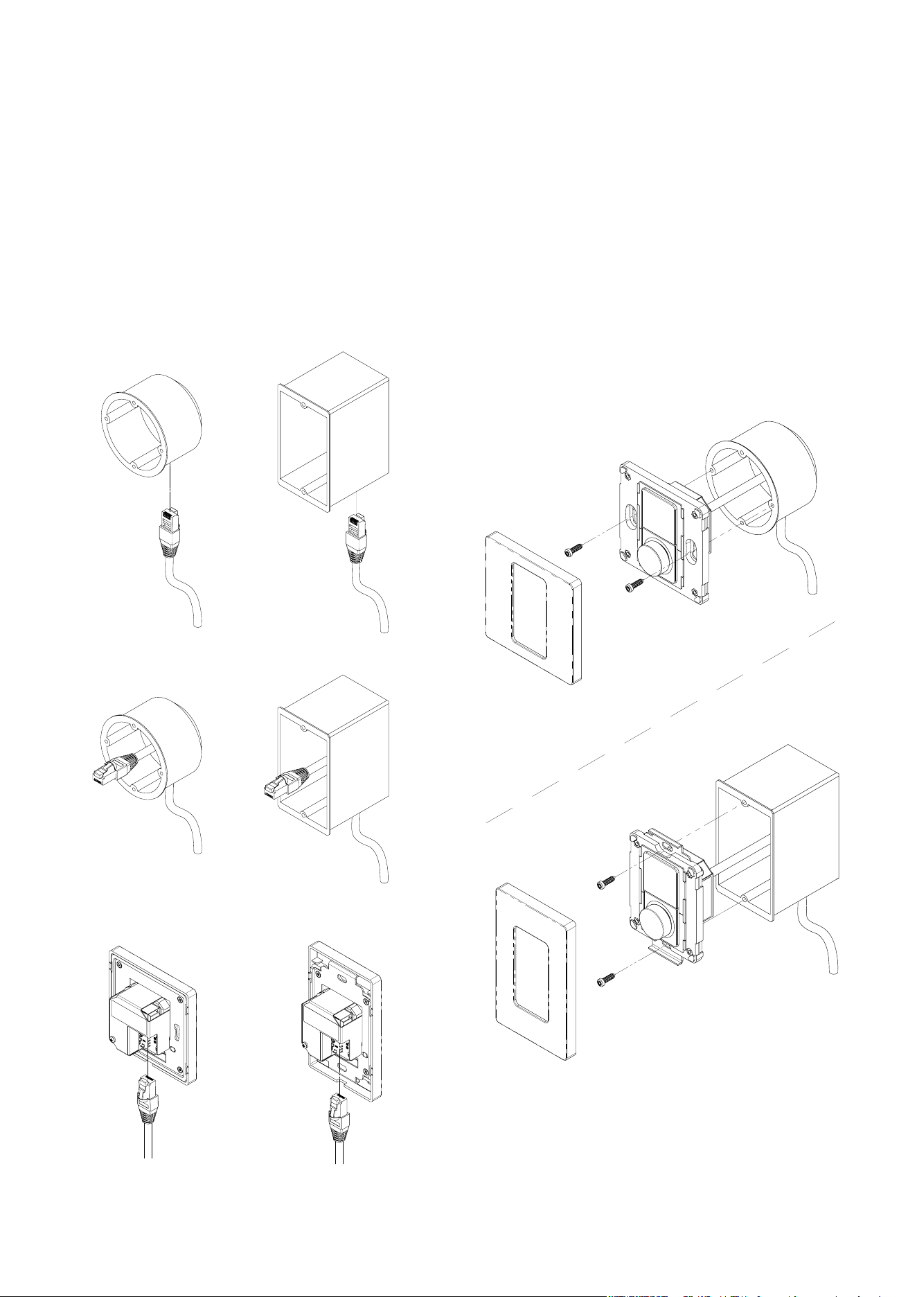
3.1 Device Mounting
Please note that this product does NOT include the in-wall
mounng electrical box and installaon screws required to
install the controller.
Use a commercially available in-wall mounng electrical
box and installaon screws suitable for the specic wall
material and installaon situaon.
1. Feed the Ethernet cable through the electrical box.
2. Mount the electrical box into the wall.
3. Connect the Ethernet cable to the Multizone Controller unit.
4. Click off the front panel.
Screw the Multizone Controller unit into the electrical
box.
- Put the front panel on - and click it into place.
4/19

Operation
4.1 Device Operation
The Mulzone Controller has been designed for easy and
intuive operaon.
Once installed and congured, the user operates all the
device’s funcons via a highly tacle rotary encoder
dial, with all relevant informaon presented via a high-
resoluon color display.
• The dial is highly sensive which makes menu
navigaon and unit adjustments a frustraon-free
experience.
• When navigang a menu or adjusng a seng by
rotang the encoder dial, the user feels a tacle change
in the units via a subtle ‘clicking’ sensaon from the dial
through their ngers.
• When operang the device by pressing and releasing
the rotary encoder dial, the user can both feel and hear
a clear click – thereby conrming the acon taken.
The three primary funcons of the device are operated as
outlined below.
1. Twisng the rotary encoder allows the user to adjust
volume and navigate menu opons.
• Twisng the rotary encoder to the le (anclockwise)
turns down the volume and twisng it to the right
(clockwise) turns up the volume.
2. Tapping the rotary encoder allows the user to change
input source.
• Switching between input sources is performed by
tapping the rotary encoder dial, twisng the rotary
encoder to view the source inputs available; and
conrming the desired choice by tapping the rotary
encoder once more.
3. Pressing and holding the rotary encoder allows the user
to access the sengs menu.
• Note that access to the sengs menu can also be
restricted via use of oponal PIN code protecon –
acvated and congured within the sengs of the
amplier Web App.
5/19
Setup
5.1 Device Setup
Note: When connecng mulple Mulzone Controller
devices to a single amplier, we recommend compleng
all stages of the setup process, before connecng and
conguring a subsequent device.
Step 1: Start Up Device
Once the Mulzone Controller is receiving power via the
connected Ethernet cable, the product will power up and
display the welcome logo for a few seconds. The welcome
logo will disappear and be replaced by the setup screen.
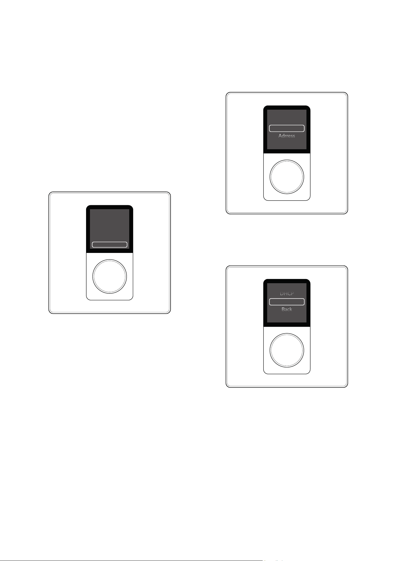
The setup screen displays the following:
• Device pairing code
• Opon to change IP address [“Edit IP Sengs”]
Step 2: Edit the Device’s IP Setting
(if required)
When the device is connected to a RTI-AMP Series
Amplier via a network router, the Mulzone Controller
will be automacally assigned an IP address (dynamic
DCHP)
– this is the default seng, and in this situaon, there is no
need to edit the IP sengs.
However, if the device is connected to a
RTI-AMP Series Amplifier via a network switch, you
must edit the IP settings to static IP.
On inial set-up, this can only be done via the device itself
and is performed by following the steps outlined below.
1. Tap the rotary encoder to conrm the acon to “Edit IP
Sengs”
2. On the display you will be presented with a set of
opons.
Use Amplier to Pair
Edit IP Sengs
3S80
(Sengs/External Devices)
IP Sengs
IP mode:DHCP
Mode
Adrress
Twist the rotary encoder one click to the le (anclockwise)
and tap the rotary encoder to conrm the selecon of the
opon labeled “MODE”.
IP Mode
Set stac IP mode
Stac
DHCP
Back
4. You will be automacally returned to the previous menu.
IMPORTANT - Jump to Step 12 if this is not the first
device you are connecting to the same amplifier!
5. Twist the rotary encoder 4 clicks to the right (clockwise)
to navigate to the opon labeled “Back”.
6. Tap the rotary encoder to conrm the selecon of the
opon “Back”.
3. Tap the rotary encoder to conrm the selecon of the
opon labeled “Stac”.
6/19
Setup
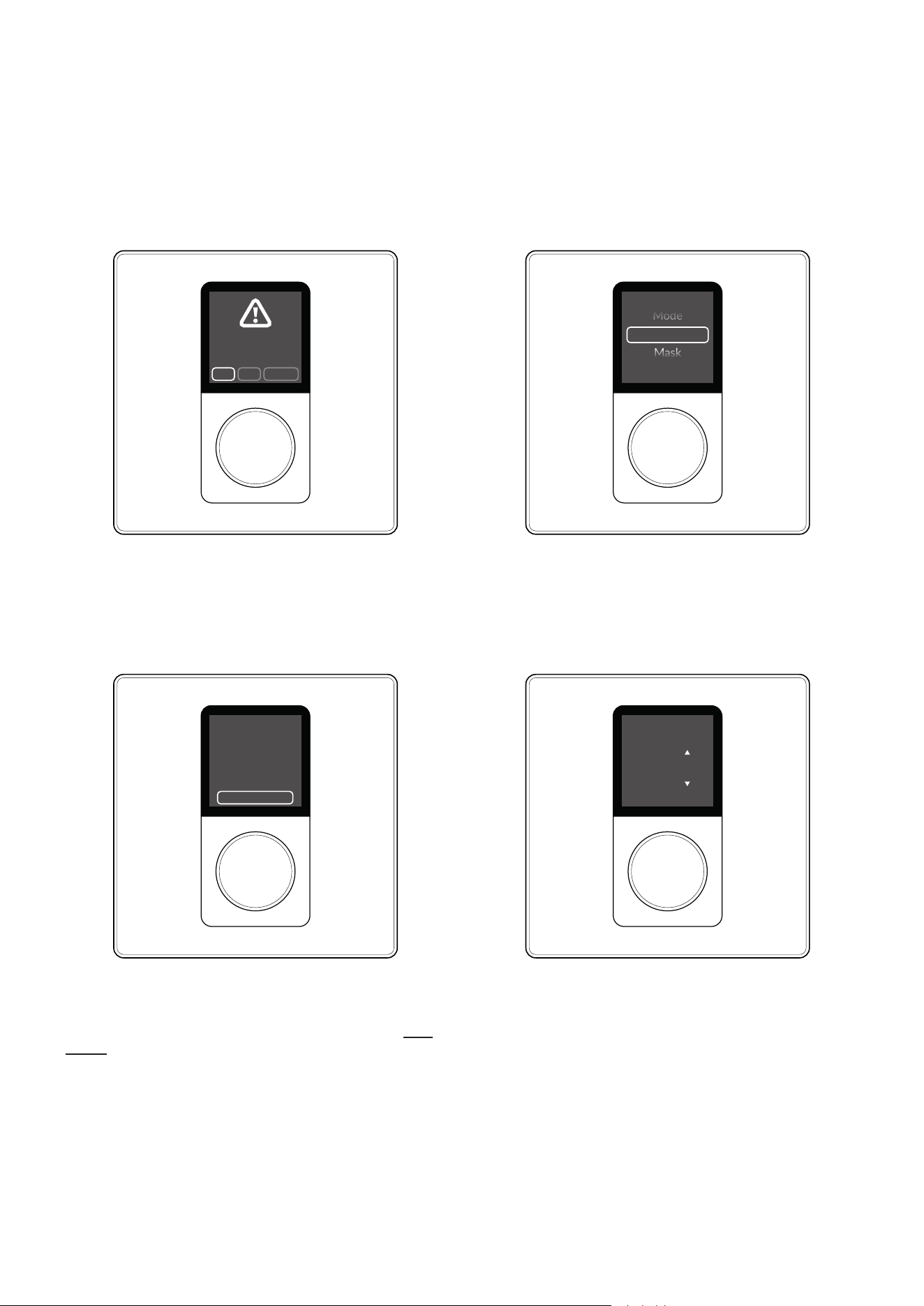
7. You will be presented with the queson
“Apply IP Changes?”
8. Tap the rotary encoder to conrm the selecon of the
opon labeled “Yes”.
9. You will now be presented with the exact same display as
at the beginning of the process, showing a pairing code –
like that shown in the image below.
NoYes Cancel
Apply IP
Changes?
Use Amplier to Pair
Edit IP Sengs
3S80
(Sengs/External Devices)
10. You have now completed the necessary steps for
eding the IP sengs required when conguring the rst
device to be connected to the amplier.
IMPORTANT – When connecng >1 devices to the
same amplier, addional acons, as described below,
must be taken aer Step 5 to ensure each device has
a unique IP address.
11. Twist the rotary encoder one click to the right
(clockwise) and tap the rotary encoder to conrm the
selecon of the opon labeled “Address”.
12. Tap the rotary encoder mulple mes unl the last digit
of the IP address is selected.
IP Sengs
192.168.64.110
Address
Mode
Mask
Set IP Address
Hold buon to exit
1 1 1
192.168.064.111
13. Twist the rotary encoder right (clockwise) to change
the nal digit of the IP address for this device – so it is not
matching those of any other device also linked to the same
amplier. (e.g., for the second device change the nal digit
to #2; for the second device change the nal digit to #3,
and so forth).
14. Tap the rotary encoder to conrm the change and exit
(as advised on the screen).
15. Twist the rotary encoder 3 clicks to the right (clockwise)
to navigate to the opon labeled “Back”.
7/19
Step 3: Connect to the amplifier using the
RTI-AMP Series Amplifier Web App
If you haven’t already, connect now to the RTI-AMP Series
Amplier via your phone, tablet or computer using the RTI-
AMP Series Amplier Web App.
Refer to the quick start guide for an RTI-AMP Series Ampli-
er if you need a reminder on how to so this.
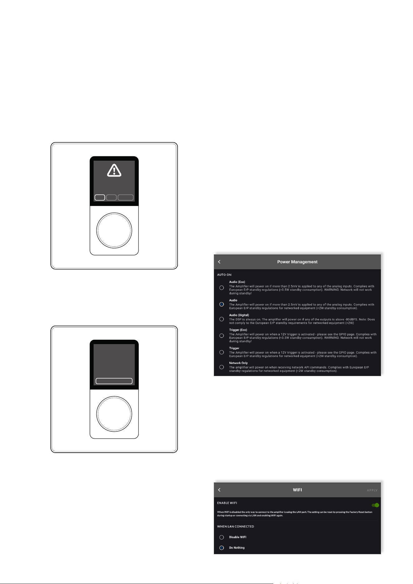
IMPORTANT –After connecting to the amplifier,
we strongly recommend changing the Power
Management setting to ”Network Only”.
There are two main reasons for this recommendaon:
• The default seng labeled “Audio” can potenally
block the (oponal) funcon of being able to success-
fully power down the amplier directly from the wall
controller.
• Seng Power Management to one of the Eco modes
[”Audio (Eco)” or ”Trigger (Eco)”] is also not recommend-
ed, as under these sengs the amplier can easily lose
connecon with the networked devices.
IMPORTANT - If accessing the Web App by
connecting to the amplifier via a wired (Ethernet)
network connection, we strongly recommend
changing the WIFI settings as outlined below.
• Under the ‘Sengs Menu’, go to ‘WIFI’ sengs and select
the opon “Disable WIFI” when LAN connected. Then click
“APPLY” in the upper right-hand corner.
Making this adjustment to the WIFI sengs will not only
avoid any potenal IP address conict, but also beer
secure access to the amplier and its networked devices.
Setup
20. You have now completed the necessary steps for
eding the IP sengs required when conguring the
second, third or further device to be connected to the
amplier.
NoYes Cancel
Apply IP
Changes?
19. You will now be presented with the exact same display
as at the beginning, showing a pairing code.
16. Push the rotary encoder to conrm the selecon of the
opon “Back”.
17. You will be presented with the queson “Apply IP
Changes?”
18. Twist the rotary encoder one click to the le
(anclockwise) and tap the rotary encoder to conrm the
selecon of the opon labeled “Yes”.
Use Amplier to Pair
Edit IP Sengs
3S80
(Sengs/External Devices)
8/19
Setup
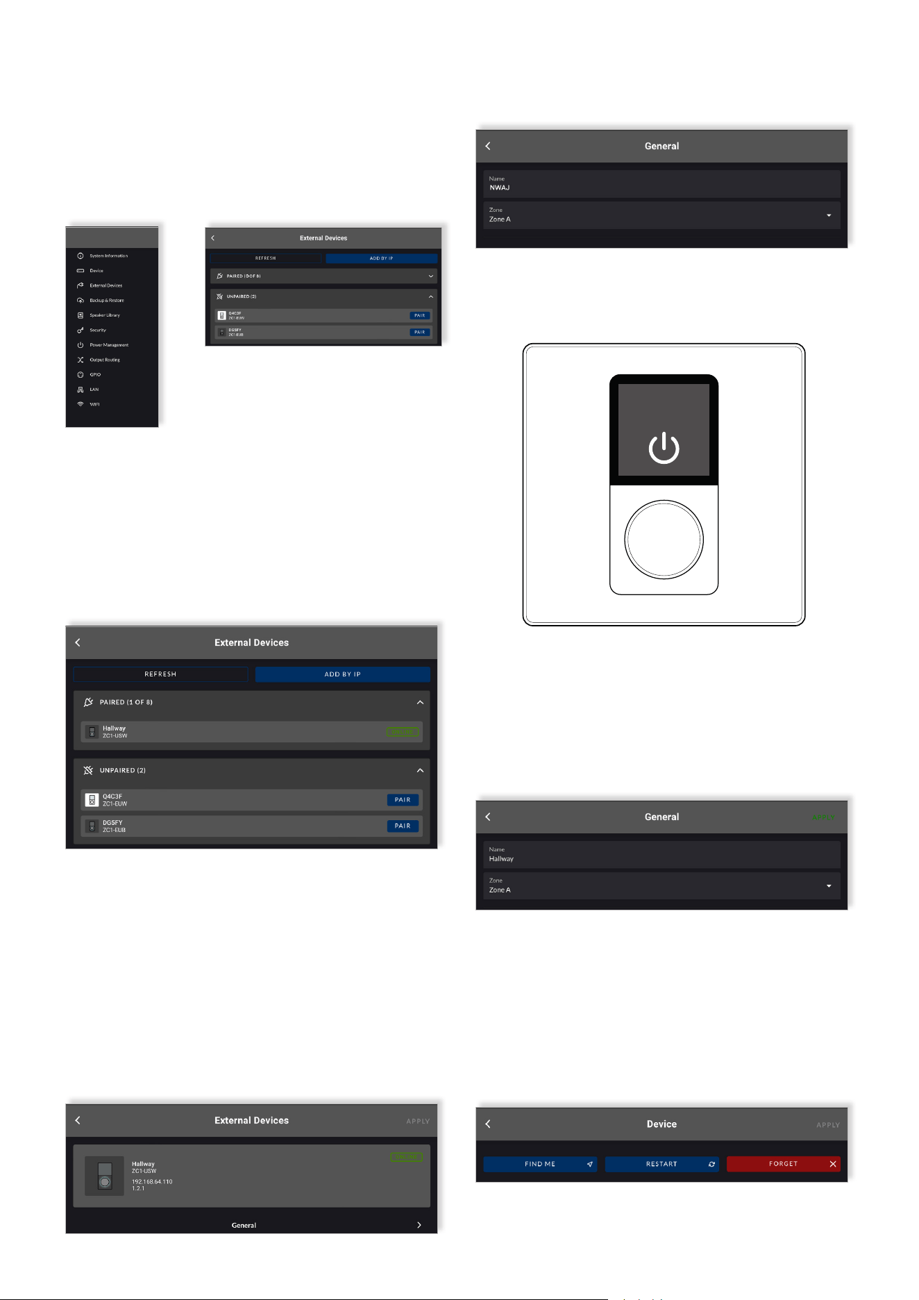
Step 4: Pair the device with the amplifier
To pair the Mulzone Controller with the RTI-AMP Series
Amplier, navigate to the menu ‘Sengs’
> ‘External Devices’ in the Web App.
Step 6: Name the device
Under the tab labeled “General” you are now recommended
to type in a name for the device.
We recommend using a name that describes the device’s
point of installaon or usage (e.g., ‘Basement Bar’).
Click “APPLY” to acvate the name change.
Step 5: Select the audio zone the device is intended
to control
In the RTI-AMP Series Amplier Web App, click on the
device shown within the paired devices menu and navigate
to the tab labeled “General”.
Assign the device to a specic audio zone, selecng the
desired zone from the drop-down menu (e.g., Zone A) that
the device is intended to control.
Noce how the new name of the zone associated with the
wall controller is instantly displayed at the top of screen of
the Mulzone Controller.
The Mulzone Controller you are conguring will be
displayed under ‘Unpaired’ devices.
Pair the device by clicking the buon labeled “PAIR” next
to the respecve Mulzone Controller.
The process of pairing the Mulzone Controller with the
RTI-AMP Series Amplier takes just a few seconds. Once
pairing is successful, the device will be shown under ‘paired
devices’ in the web app, and the green “ONLINE” icon will
be displayed alongside it.
Zone A
iPhone
The Mulzone Controller is now congured and able to
remotely control the volume and source input of the zone it
is associated with.
Individual Mulzone Controller idencaon can be
established by selecng the Find Me opon in the
‘Sengs’> ‘External Devices’ in the Web App. The display
and rotary encoder illuminaon of the connected device
will ash.
9/19
Noce how the new name of the zone associated with the
wall controller is instantly displayed at the top of screen of
the Mulzone Controller.
Configuration
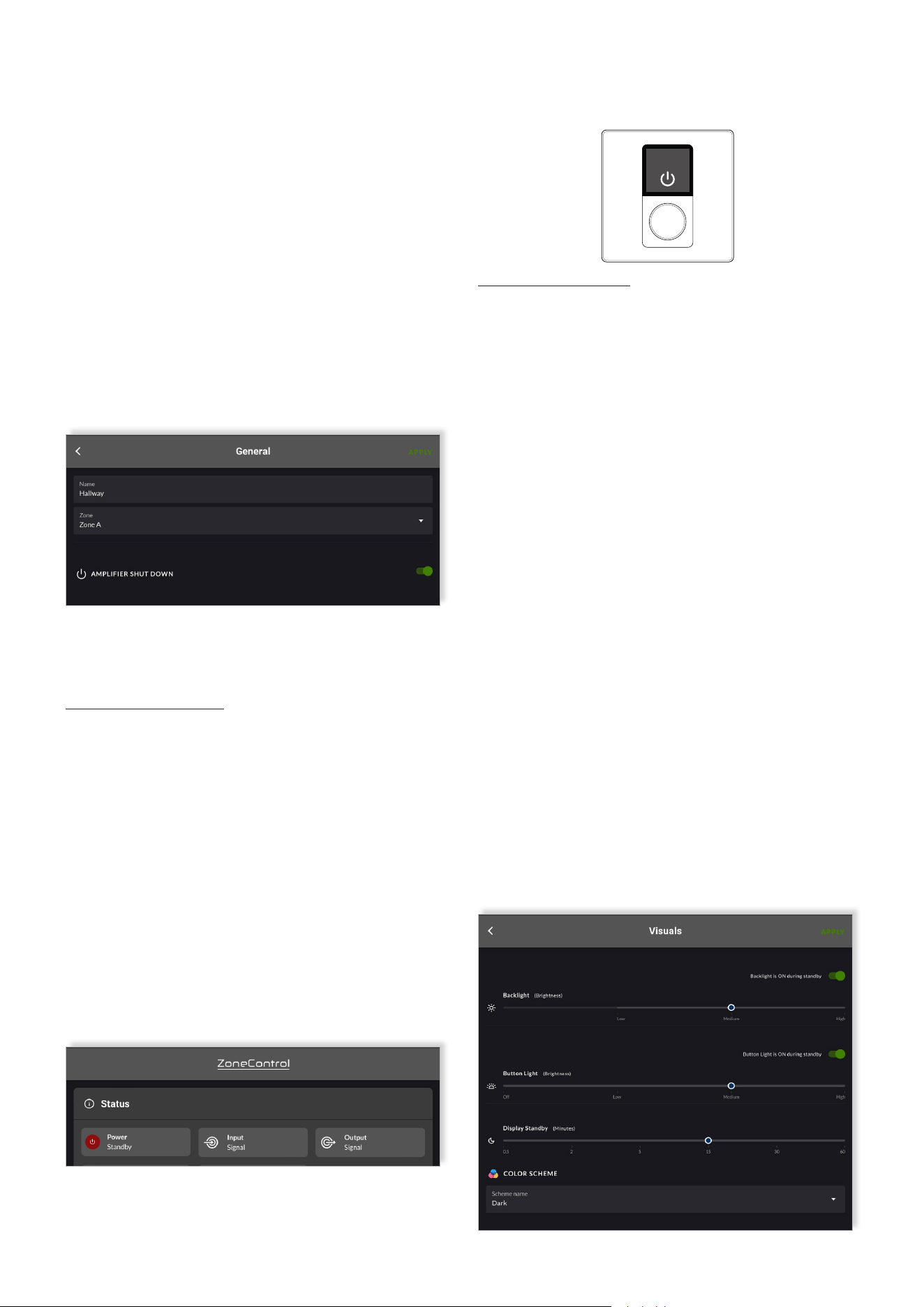
6.1 Amplifier Power On/Off Feature
The amplier can be both powered on and o, directly from
the Mulzone Controller.
By default, this funcon is not acve and so needs to be
rst acvated within the sengs of the device via the
RTI-AMP Series Amplier Web App.
Under the tab labeled “General” there is an opon at the
boom labeled “AMPLIFIER SHUT DOWN”, and a toggle
switch to the right.
Firstly, toggle the switch so it displays as acve (green).
Secondly, click “APPLY” in the top right-hand corner to
acvate the feature.
Once the feature has been acvated, it is possible for the
amplier to be both powered on and o, directly from the
Mulzone Controller.
To turn the amplifier off (into standby mode), follow the
steps outlined below.
1. Press and hold the rotary encoder unl the opon
“Power O Amp” appears (shows below the seng
menu when the feature is acvated).
2. Tap the rotary encoder to conrm the selecon of the
opon acon “Power O Amp”.
3. You will be presented with the queson
“Power Down Amplier?”
4. Twist the rotary encoder to highlight the opon “Yes”
and tap the rotary encoder to conrm the selecon.
When the amplier is in standby power mode, it will be
communicated via both the dashboard secon of the Web
App, and on the display screen of the Mulzone Controller
itself. (See next column top right)
To turn the amplifier on (back from standby mode), follow
the steps outlined below.
1. Tap the rotary encoder.
2. You will be presented with the queson
“Power Up Amplier?”
3. Twist the rotary encoder to highlight the opon “Yes”
and tap the rotary encoder to conrm the selecon.
6.2 Display Screen Back-light Settings:
Brightness - Customization
Thanks to the color LCD display the user can clearly see
the zone the controller is associated with, the audio source
input that is selected and the current volume level. The
high-resoluon screen provides enough space for a font
size adequate for the user to read and navigate text and
menu sengs.
The intensity of the display screen’s back-light can be
adjusted to suit the use environment and user preference.
The adjustment can be made directly on the wall controller
itself or changed within the RTI-AMP Series Amplier Web
App.
Three seng levels are possible:
• Low (least bright)
• Medium
• High (most bright)
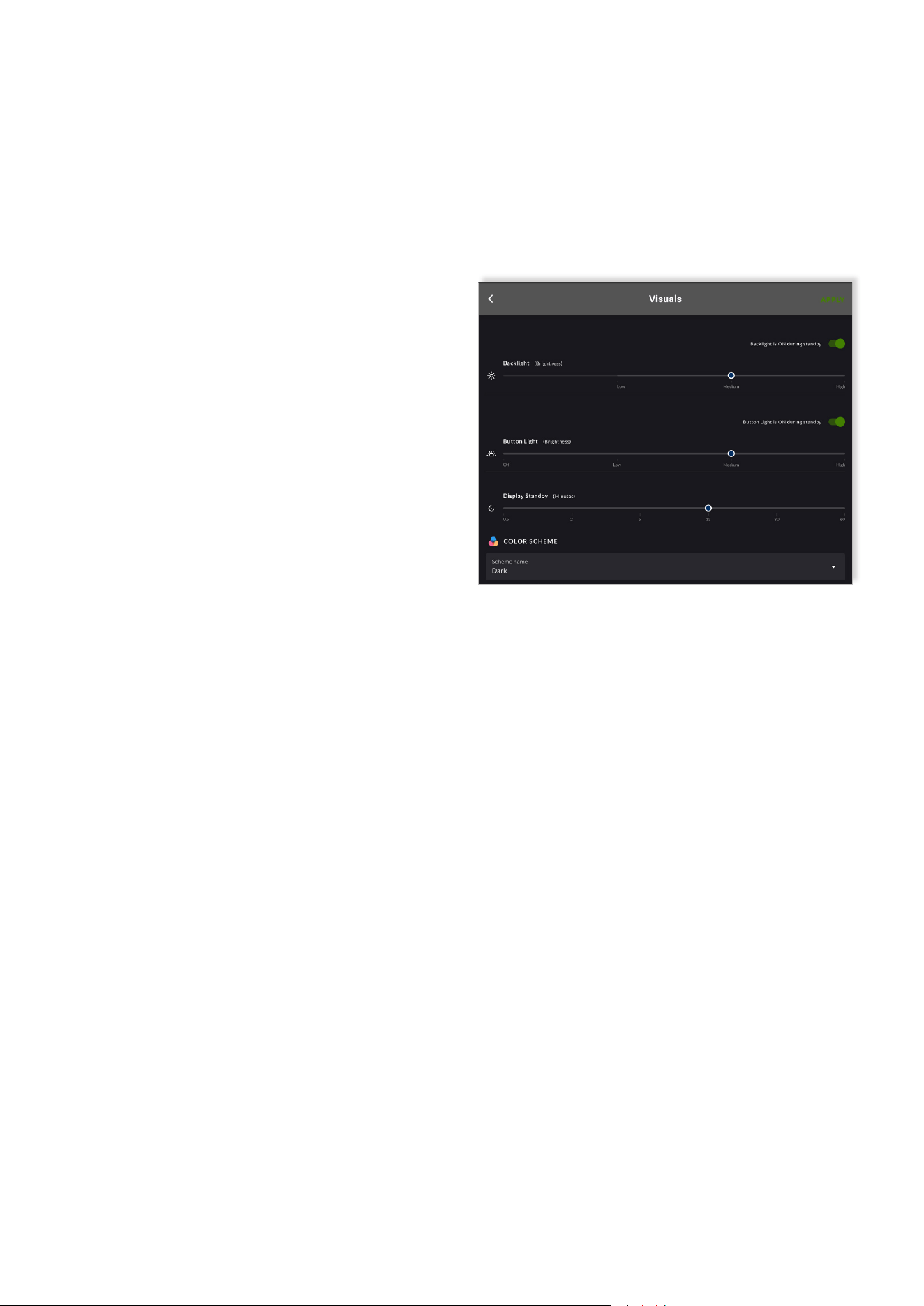
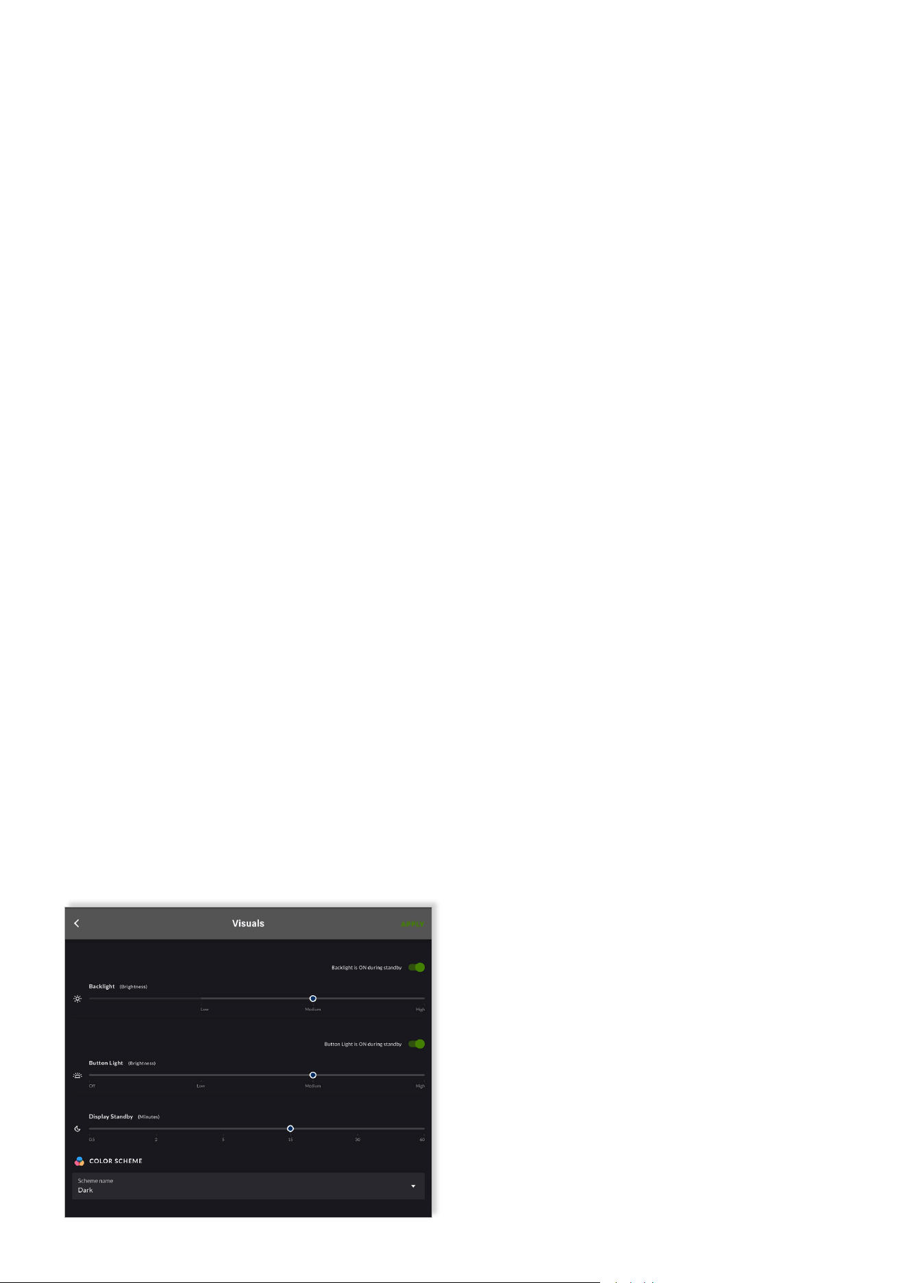
In the RTI-AMP Series Amplier Web App, click on the
device shown within the paired devices menu and navigate
to the tab labeled “Visuals”. Select the preferred brightness
level and, then click the buon labeled “APPLY” in the top
right-hand corner to acvate the change.
Zone A
iPhone
10/19
Configuration
6.3 Display Screen Back-light Settings:
Standby - Customization
To enhance the user experience, the back-light of the
display can also be deacvated, when the is in standby
mode.
This feature is especially valuable when lighng condions
of the room change – e.g., from bright sunlight during the
day to darker condions in the evening. Please note that
when the back-light is deacvated, the screen appears
completely blank to the user, and no longer communicates
the zone, source input or volume level of the associated
zone.
The intensity of the display screen’s back-light can also
be customized within the sengs menu of the Mulzone
Controller itself. To change the intensity of the display
screen’s back-light via the Mulzone Controller, follow the
steps outlined below.
1. Press and hold the rotary encoder until the settings
menu appears.
2. Tap the rotary encoder to confirm the selection of the
“Settings” menu.
3. Tap the rotary encoder to confirm the selection of the
“Visuals” menu.
4. Tap the rotary encoder to confirm the selection of the
“Back-light” menu.
5. Twist the rotary encoder left and right to explore the
options available, as shown on the screen.
6. Tap the rotary encoder to confirm the desired
intensity of the display screen’s backlight.
7. Twist the rotary encoder one click to the right
(clockwise) to navigate to the option labeled “Back”.
8. Tap the rotary encoder to confirm the selection of the
option action “Back”.
9. Twist the rotary encoder 2 clicks to the right
(clockwise) to navigate to the option labeled “Back”.
10. Tap the rotary encoder to confirm the selection of
the option action “Back”.
11. You will be presented with the question “Apply
Visual Changes?”
12. Twist the rotary encoder to highlight the
option “Yes” and tap the rotary encoder to confirm the
selection .
13. Twist the rotary encoder 2 clicks to the right
(clockwise) to navigate to the option labeled “Back”.
14. Tap the rotary encoder to confirm the selection of
the option action “Back”.
15. You are now returned to the primary screen view
displaying the zone, source input and volume level of
the associated zone.
The display screen can also be deacvated when the
display is in standby mode within the sengs menu of the
Mulzone Controller itself.
To deacvate the screen display when the display is in
standby mode via the Mulzone Controller, simply follow
the steps outlined below.
1. Press and hold the rotary encoder until the settings
menu appears.
2. Tap the rotary encoder to confirm the selection of the
“Settings” menu.
3. Tap the rotary encoder to confirm the selection of the
“Visuals” menu.
4. Tap the rotary encoder to confirm the selection of the
“Back-light” menu.
5. Twist the rotary encoder one click to the left (anti-
clockwise) to navigate to the option labeled “Standby”.
6. Tap the rotary encoder to confirm the selection of the
“Standby” menu.
7. Twist the rotary encoder left and right to toggle be-
tween the display standby options “ON” and “OFF”.
8. Tap the rotary encoder to confirm your preferred
display standby setting (ON means display screen back-
light remains on even when Multizone Controller is in
standby mode).
9. Twist the rotary encoder 2 clicks to the right (clock-
wise) to navigate to the option labeled “Back”.
10. Tap the rotary encoder to confirm the selection of
the option action “Back”.
The adjustment can be made directly on the wall controller
itself or changed within the RTI-AMP Series Amplier Web
App.
Using the Web App ”Visuals” tab, rstly move the toggle
switch to the le – so the text “Back-light is OFF during
standby” is displayed.
Aerwards, click the buon labeled “APPLY” in the top
right-hand corner to acvate the feature.
11/19
Configuration
6.4 Rotary Encoder Dial Back-light Settings:
Brightness - Customization
The intensity of the back-light behind the rotary encoder
dial can be adjusted to suit the use environment and user
preference. Four seng levels are possible:
• O (no light)
• Low (least bright)
• Medium
• High (most bright)
The adjustment can be made directly on the wall controller
itself or changed within the RTI-AMP Series Amplier Web
App.
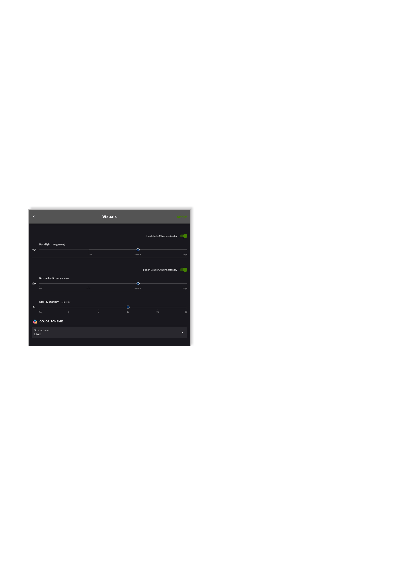
Using the Web App, the intensity of rotary encoder dial
back-light can be quickly changed via the slider located at
in the center of the “Visuals” tab.
Simply choose the preferred brightness level and, then click
the buon labeled “APPLY” in the top right-hand corner to
acvate the change.
The intensity of the back-light behind the rotary encoder
dial can also be customized within the sengs menu of the
Mulzone Controller itself. To change the intensity of the
back-light behind the rotary encoder dial via the Mulzone
Controller, simply follow the steps outlined below.
1. Press and hold the rotary encoder unl the sengs
menu appears.
2. Tap the rotary encoder to conrm the selecon of the
“Sengs” menu.
3. Tap the rotary encoder to conrm the selecon of the
“Visuals” menu.
4. Twist the rotary encoder one click to the right
(clockwise) and tap the rotary encoder to conrm the
selecon of the opon labeled “Buon Light”.
5. Tap the rotary encoder to conrm the selecon of the
opon labeled “Brightness”.
6. Tap the rotary encoder to conrm the selecon of the
“Brightness” menu.
7. Twist the rotary encoder le and right to toggle
between the four opons “OFF”; “LOW”; “MID”;
“HIGH”.
8. Tap the rotary encoder to conrm your preferred
seng.
9. Twist the rotary encoder 1 click to the right
(clockwise) to navigate to the opon labeled “Back”.
10. Tap the rotary encoder to conrm the selecon of
the opon acon “Back” .
11. Twist the rotary encoder 1 click to the right
(clockwise) to navigate to the opon labeled “Back”.
12. Tap the rotary encoder to conrm the selecon of
the opon acon “Back”.
13. You will be presented with the queson “Apply
Visual Changes?”
14. Twist the rotary encoder to highlight the opon
“Yes” and tap the rotary encoder to conrm the
selecon.
15. Twist the rotary encoder 2 clicks to the right
(clockwise) to navigate to the opon labeled “Back”.
16. Tap the rotary encoder to conrm the selecon of
the opon acon “Back”.
17. You are now returned to the primary screen view
displaying the zone, source input and volume level of
the associated zone.
12/19
11. Twist the rotary encoder 2 clicks to the right (clock-
wise) to navigate to the option labeled “Back”.
12. Tap the rotary encoder to confirm the selection of
the option action “Back”.
13. You will be presented with the question “Apply Visu-
al Changes?”
14. Twist the rotary encoder to highlight the option
“Yes” and tap the rotary encoder to confirm the selec-
tion.
15. Twist the rotary encoder 2 clicks to the right (clock-
wise) to navigate to the option labeled “Back”.
16. Tap the rotary encoder to confirm the selection of
the option action “Back”.
17. You are now returned to the primary screen view
displaying the zone, source input and volume level of
the associated zone.
Conguraon
The back-light of the rotary encoder dial can also be
deacvated when the display is in standby mode, within
the sengs menu of the Mulzone Controller itself.
To deacvate the back-light of the rotary encoder dial
when the display is in standby mode via the Mulzone
Controller,
simply follow the steps outlined below.
1. Press and hold the rotary encoder unl the sengs
menu appears.
2. Tap the rotary encoder to conrm the selecon of the
“Sengs” menu.
3. Tap the rotary encoder to conrm the selecon of the
“Visuals” menu.
4. Twist the rotary encoder one click to the right
(clockwise) and tap the rotary encoder to conrm the
selecon of the opon labeled “Buon Light”.
5. Twist the rotary encoder one click to the le
(anclockwise) and tap the rotary encoder to conrm
the selecon of the opon labeled “Standby”.
6. Twist the rotary encoder le and right to toggle
between the display standby opons “ON” and “OFF”.
7. Tap the rotary encoder to conrm your preferred
display standby seng (ON means the rotary
encoder dial backlight remains on even when Zone
Controller is in standby mode).
8. Twist the rotary encoder 2 clicks to the right
(clockwise) to navigate to the opon labeled “Back”.
9. Tap the rotary encoder to conrm the selecon of the
opon acon “Back”.
10. Twist the rotary encoder 1 click to the right
(clockwise) to navigate to the opon labeled “Back”.
11. Tap the rotary encoder to conrm the selecon of
the opon acon “Back”.
12. You will be presented with the queson
“Apply Visual Changes?”
13. Twist the rotary encoder to highlight the
opon “Yes” and tap the rotary encoder to conrm the
selecon.
14. Twist the rotary encoder 2 clicks to the right
(clockwise) to navigate to the opon labeled “Back”.
15. Tap the rotary encoder to conrm the selecon of
the opon acon “Back”.
16. You are now returned to the primary screen view
displaying the zone, source input and volume level of
the associated zone.
6.5 Rotary Encoder Dial Back-light Settings:
Standby - Customization
To facilitate the ideal user experience, the back-light of
the rotary encoder dial can also be deacvated, when the
display is in standby mode.
This feature is especially valuable when lighng condions
of the room change – e.g., from bright sunlight during the
day to darker condions in the evening.
The adjustment can be made directly on the wall controller
itself or changed within the RTI-AMP Series Amplier Web
App.
Using the Web App, rstly move the toggle switch to the
le – so the text “Buon Light is OFF during standby” is
displayed.
Aerwards, click the buon labeled “APPLY” in the top
right-hand corner to acvate the feature.
13/19
Configuration
6.6 Display Screen Colour Scheme - Customization
Thanks to the color LCD display the user can clearly see
the zone the controller is associated with, the audio source
input that is selected and the current volume level.
The high-resoluon screen provides enough space for a
font size adequate for the user to read and navigate text
and menu sengs.
A choice of four dierent color schemes also provides the
possibility to customize the display to best match the use
environment and/or personal preference.
• BLUE = White Text on Blue Background.
• DARK = White Text on Dark Grey Background.
• LIGHT = Black Text on Light Grey Background.
• ORANGE= Orange Text on Dark Grey Background.
Note, that by default the color scheme is set to “DARK”.
Customizaon can be made within the RTI-AMP Series
Amplier Web App, or directly via the Mulzone Controller
itself.
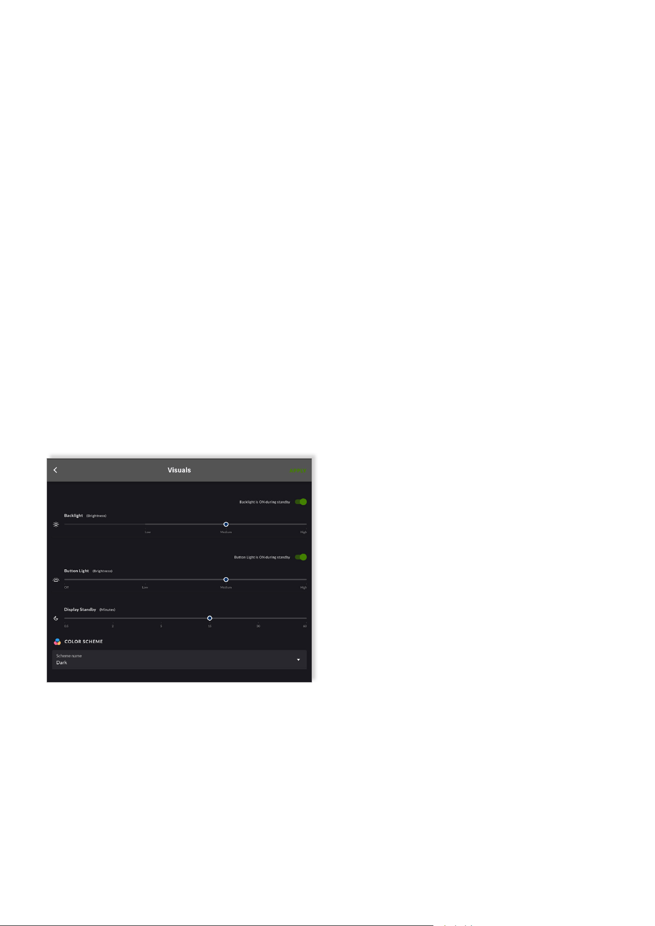
Using the Web App, the color scheme can be quickly
changed via the drop-down menu located at the boom
of the “Visuals” tab. Simply choose the preferred color
scheme, and then click the buon labeled “APPLY” in the
top right-hand corner to acvate the change.
The color scheme can also be customized within the
sengs menu of the Mulzone Controller itself. To change
the screen color scheme via the Mulzone Controller,
simply follow the steps outlined below.
1. Press and hold the rotary encoder unl the sengs
menu appears.
2. Tap the rotary encoder to conrm the selecon of the
“Sengs” menu.
3. Tap the rotary encoder to conrm the selecon of the
“Visuals” menu.
4. Twist the rotary encoder one click to the le
(anclockwise) and tap the rotary encoder to conrm
the selecon of the opon labeled “Color Scheme”.
5. Twist the rotary encoder le and right to explore the
opons available, as shown on the screen.
6. Tap the rotary encoder to conrm the desired color
scheme.
7. Twist the rotary encoder to the right (clockwise) unl
you have navigated to the opon labeled “Back”.
8. Tap the rotary encoder to conrm the selecon of the
opon acon “Back”.
9. Twist the rotary encoder 3 clicks to the right
(clockwise) to navigate to the opon labeled “Back”.
10. Tap the rotary encoder to conrm the selecon of
the opon acon “Back”.
11. You will be presented with the queson
“Apply Visual Changes?”
12. Twist the rotary encoder to highlight the
opon “Yes” and tap the rotary encoder to conrm the
selecon.
13. Twist the rotary encoder 2 clicks to the right
(clockwise) to navigate to the opon labeled “Back”.
14. Tap the rotary encoder to conrm the selecon of
the opon acon “Back”.
15. You are now returned to the primary screen view
displaying the zone, source input and volume level of
the associated zone.
14/19
Configuration
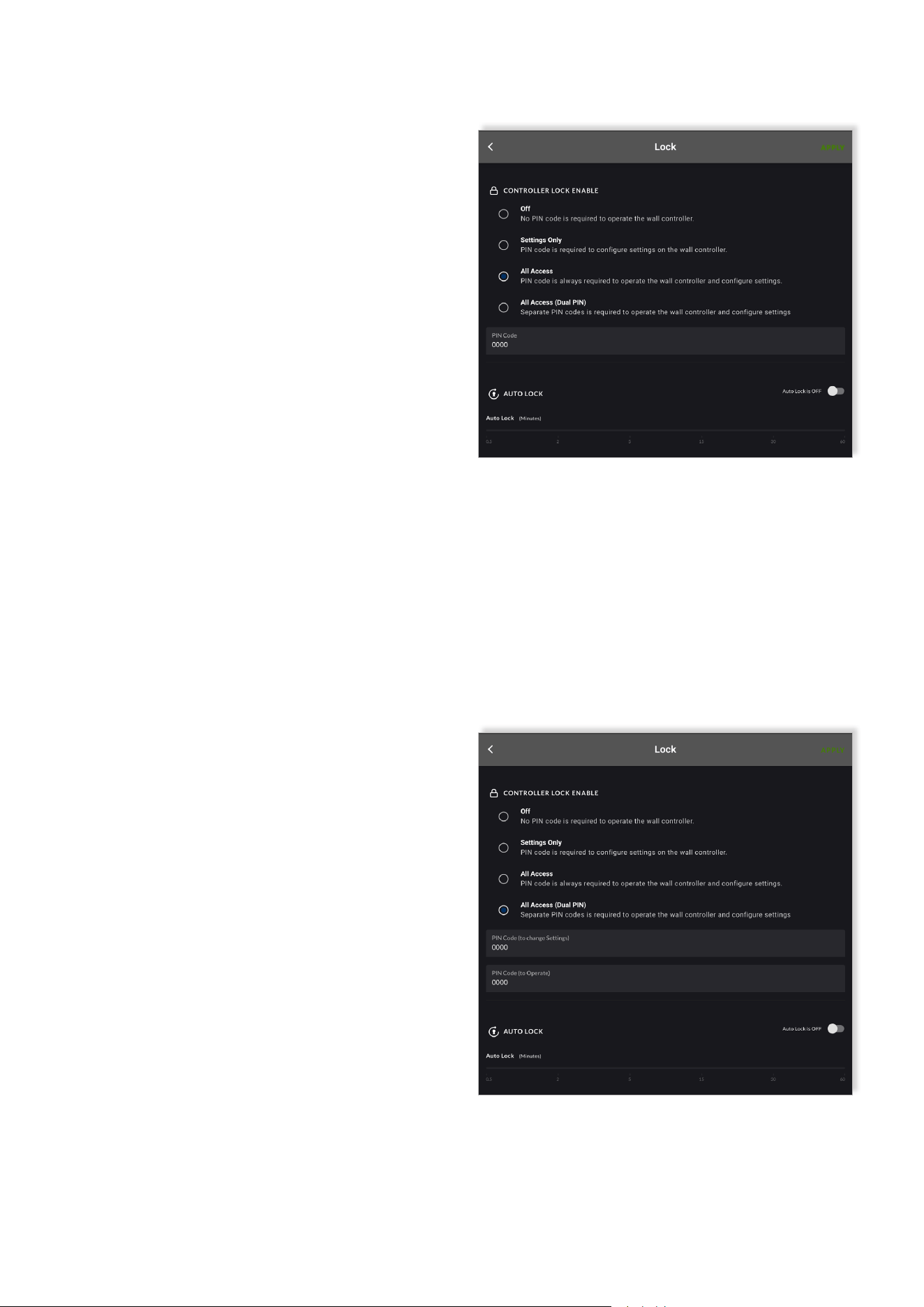
6.8.2 Level B: “All Access” - Applied to Protect
Access To All Functions
Typical Use Case Scenario: Example - Mulzone Controller
devices are placed within easy reach of customers of a café.
Enabling the local user lock funcon and seng it to “All
Access” prevents the possibility of customers adjusng the
volume, switching the audio source, or making any other
adjustment to the installed system.
• Unl unlocked, none of the funcons of the Mulzone
Controller can be accessed.
• If a user aempts to use the device, they are prompted
to enter the correct PIN code on the device – turning the
rotary encode dial to select each digit on the screen; and
pushing the dial to conrm each digit.
• Once successfully unlocked, funcons become accessible.
• Note: To enter the ”Sengs” menu you will be prompted
to enter the PIN code again – this helps ensure the security
of the device whilst the Auto Lock funcon is o.
Steps To Setup:
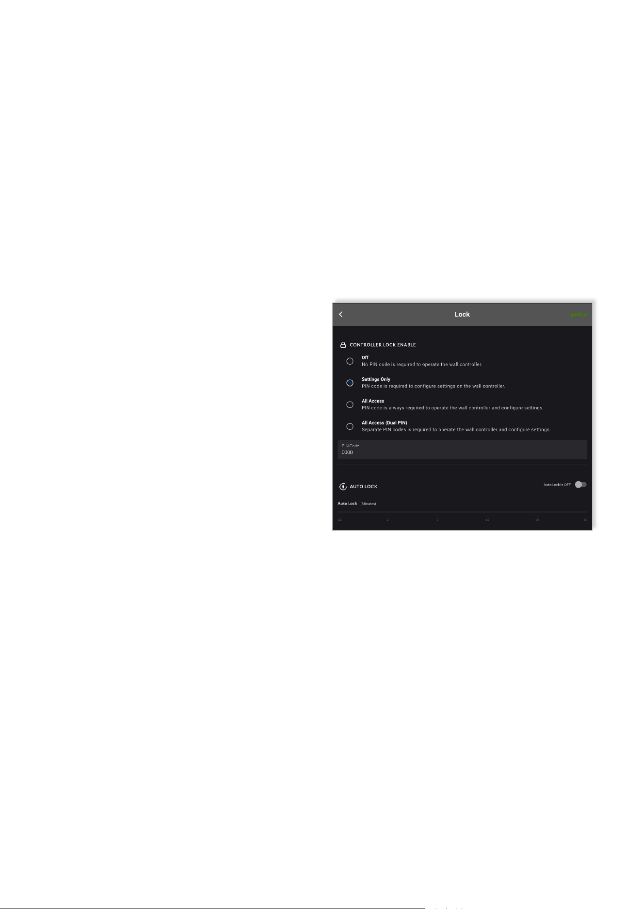
1. Using the RTI-AMP Series Amplier Web
App, navigate to the “Lock” tab and select the
opon “Sengs Only” shown under the headline
“CONTROLLER LOCK ENABLE”.
2. Type into the box labeled “PIN Code” a 4-digit PIN
code of your choice (we recommend changing the PIN
code, otherwise it will remain ‘0000’).
3. Click the buon labeled “APPLY” in the top right-
hand corner to acvate the feature as congured.
Note that the “Auto Lock” funcon is NOT an available
opon under this second level. The locking of the sengs
menu applies all the me, from the instant the opon is
applied in the Web App.
6.7 Local User Lock and Unlock (PIN Code Protecon)
A 4-digit numerical pin code can be set, reset, and enabled
within the RTI-AMP Series Amplier Web App to restrict
usage of the device.
When enabled, no one can operate the device and/or
adjust the sengs - unless they are able to enter the
correct PIN code. This makes it possible to place devices in
areas where unauthorized room users have easy access to
the device.
Note that the PIN code can always be reset via the Web
App. This solves the problem of potenally forgoen PIN
codes, whilst also providing the opportunity to change the
PIN code if circumstances change.
The PIN code protecon can either be kept deacvated
(“OFF”) or applied at three disnct levels: (A) “Sengs
Only”; (B) “All Access”, and (C) All Access (Dual PIN).
6.8.1 Level A: “Settings Only” - Applied to Protect
Access to The Settings Menu Only
Typical Use Case Scenario: Example – Mulzone Controller
devices are placed within easy reach of authorized users
(e.g., workers) of a café. Enabling the local user lock
funcon and seng it to “Sengs Only” allows the users
to adjust volume and switch audio source, but prevents the
users being able to customize the device, change crical
sengs or reset the device.
• All funcons of the wall controller are available, and
the device remains completely unlocked for use by any
user with physical access to the device.
• Only when the user aempts to access the
“Sengs” menu are they prompted to enter the correct
PIN code on the device – turning the rotary encode dial
to select each digit on the screen; and pushing the dial
to conrm each digit.
• If successfully unlocked, all funcons under the
sengs menu become accessible.
• Unl the correct PIN code is entered, the funcons
inaccessible to the user include:
- Visuals (sengs relang to customizaon of
standby, back-lights and color scheme).
- Reset Device (ability to completely reset the
device).
- IP Sengs (ability to adjust the IP sengs of the
device).
15/19
Configuration
Steps to Setup:
1. Using the Web App, navigate to the “Lock” tab and
select the opon “All Access” shown under the headline
“CONTROLLER LOCK ENABLE”.
2. Type into the box labeled “PIN Code” a 4-digit PIN
code of your choice (we recommend changing the PIN
code, otherwise it will remain ‘0000’).
3. Toggle to the right the switch labeled “Auto Lock” - it
will turn green (acve) and display the label
“Auto Lock is ON”.
4. Using the slider, select the desired period of me
to elapse before the controller is locked, and thus
requiring the entering of the correct PIN code to
unlock. (We suggest that under many circumstances the
shortest period of 30 seconds would be suitable).
5. Finally, click the buon labeled “APPLY” in the top
right-hand corner to acvate the feature as congured.
6. Once acvated, you can choose to manually lock the
device immediately, or let the device automacally lock
itself aer the period of period of me selected on the
Auto Lock slider.
7. To manually lock the device immediately, do as
described.
• Press and hold the rotary encoder of the device
unl the opon “Lock Controller” appears on the
display screen.
• Tap the rotary encoder to conrm the acon
to “Lock Controller” - you will be immediately
presented with the message “Controller Locked”, and
thereaer a padlock icon will appear on the display
screen of the device; indicang the device is now
locked – thus requiring the entering of a PIN code to
unlock.
8. To let the device automacally lock itself, do as
described.
• Wait unl the period of me selected on the Auto
Lock slider has elapsed. You will subsequently noce
a padlock icon appear on the display screen of the
device, indicang the device requires the entering of
a PIN code to unlock.
9. To unlock the device, the user must enter the correct
PIN code on the device. This is performed by turning
the rotary encode dial to select each digit on the
screen; and pushing the dial to conrm each digit.
16/19
6.8.3 Level C: “All Access (Dual PIN)” - Applied to
Protect Access To All Functions with Dual PIN
A further level of security is available with Opon C
enabling dierent PIN controlled access to Mulzone
Controller operaon and sengs.
This opon enables, for example, operators with dierent
responsibilies to have access only to the funcons
appropriate to their roles.
Opon C setup is carried out in a similar manner to Opon
B described in Secon 6.8.2. the only dierence is that two
four digit PINs are required.
Configuration
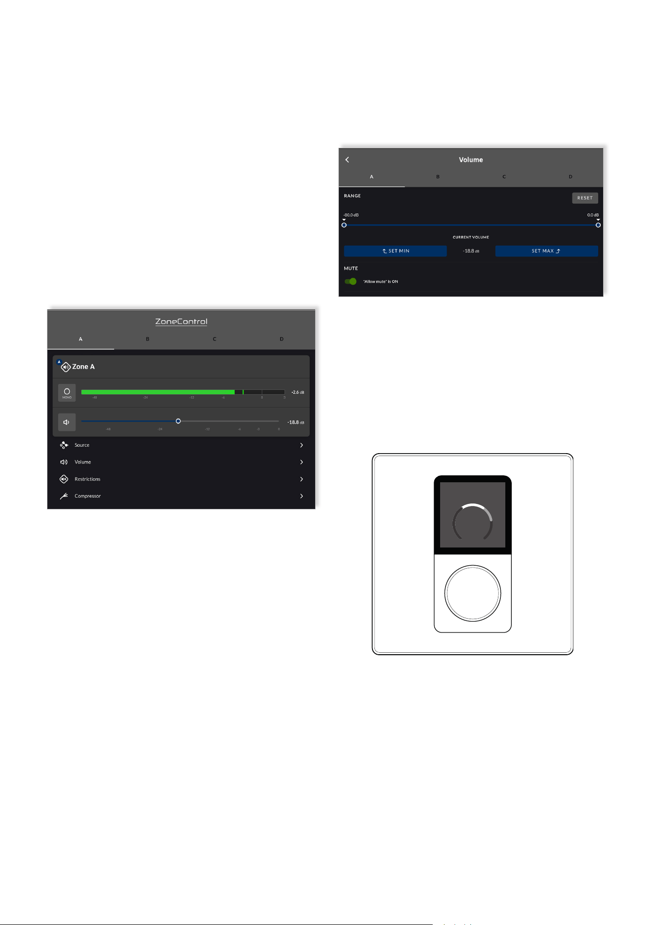
The minimum and maximum volume limits are set using
a slider found within the secon labeled “RANGE”. For
accuracy, volume sengs are displayed in decibels (dB)
(see below).
On the device, the end user is made visually aware of the
volume range limitaon when adjusng the volume level
(see below).
Note that as a convenience to the user, the volume sengs
on the device are always displayed as a relave level on a
scale of 0 – 100, rather than in decibels.
Note that if the volume is turned below the minimum level,
the output is completely muted, and the mute icon is shown
on the display screen.
Zone A
60
17/19
6.9 Volume Control (Range) Limitation
A lower (minimum) and upper (maximum) volume limitaon
can be applied to the zone the device is congured to
control.
This feature is especially valuable in scenarios where the
total power of the channel output greatly exceeds the
volume suitable for the installaon environment.
The feature is also very useful to apply in scenarios where
it is preferred the volume does not fall below a certain level
- with the excepon of complete mung.
Within the RTI-AMP Series Amplier Web App, this feature
can be found by navigang to the volume menu of the
Zone
Tab, within the Web App (see below).
It is also possible to disable the amplier zone mute
funcon. This can be parcularly signicant in situaons
where important informaon potenally needs to be heard
in a specic zone. To disable or enable the mute funcon,
toggle the ”Allow mute” switch in Volume menu of the Zone
Tab.
Reset
7.1 Device Reset
It is possible to reset a Mulzone Controller back to its fac-
tory-default state. When reseng the device, any previous
sengs including IP address informaon is cleared.
The use of this funcon is only required in exceponal
circumstances whereby a complete device reset is
necessary.
To perform a complete device reset, follow the steps
outlined below.
1. Press and hold the rotary encoder unl the
“Sengs” menu appears.
2. Tap the rotary encoder to conrm the selecon of the
“Sengs” menu.
3. Twist the rotary encoder one click to the le
(anclockwise) and tap the rotary encoder to conrm
the selecon of the opon labeled “Reset Device”
4. Tap the rotary encoder to conrm the selecon of the
opon acon “Reset Device”.
5. You will be presented with the queson
“Reset to Factory Defaults?”
6. Twist the rotary encoder to highlight the opon “Yes”
and tap the rotary encoder to conrm the selecon.
7. Aer a few seconds the device will turn o, then
restart and show a new paring code on the display
screen.
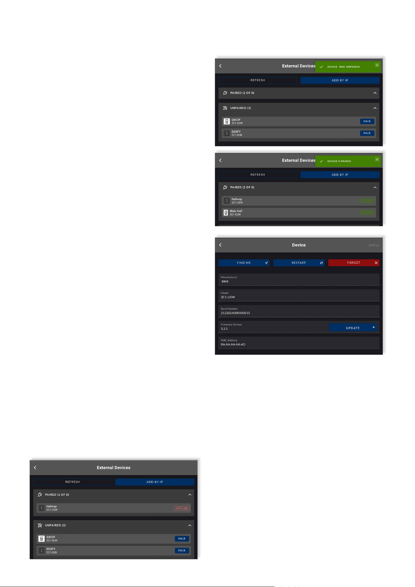
8. In the Web App, you will noce the device you just
reset shows up with a red box stang the device is
“Oine” (as shown below).
9. In the Web App, click on the device and navigate to
the “Device” tab.
10. In the boom right-hand corner of the device tab
there is a red buon labeled “Forget Device” – click this
to completely remove the device from the system.
11. You will be returned to the “External Devices”
page and a green pop-up will state “DEVICE WAS
UNPAIRED” – conrming the compleon of the process.
12. The device is now ready to be re-paired and
congured.
18/19
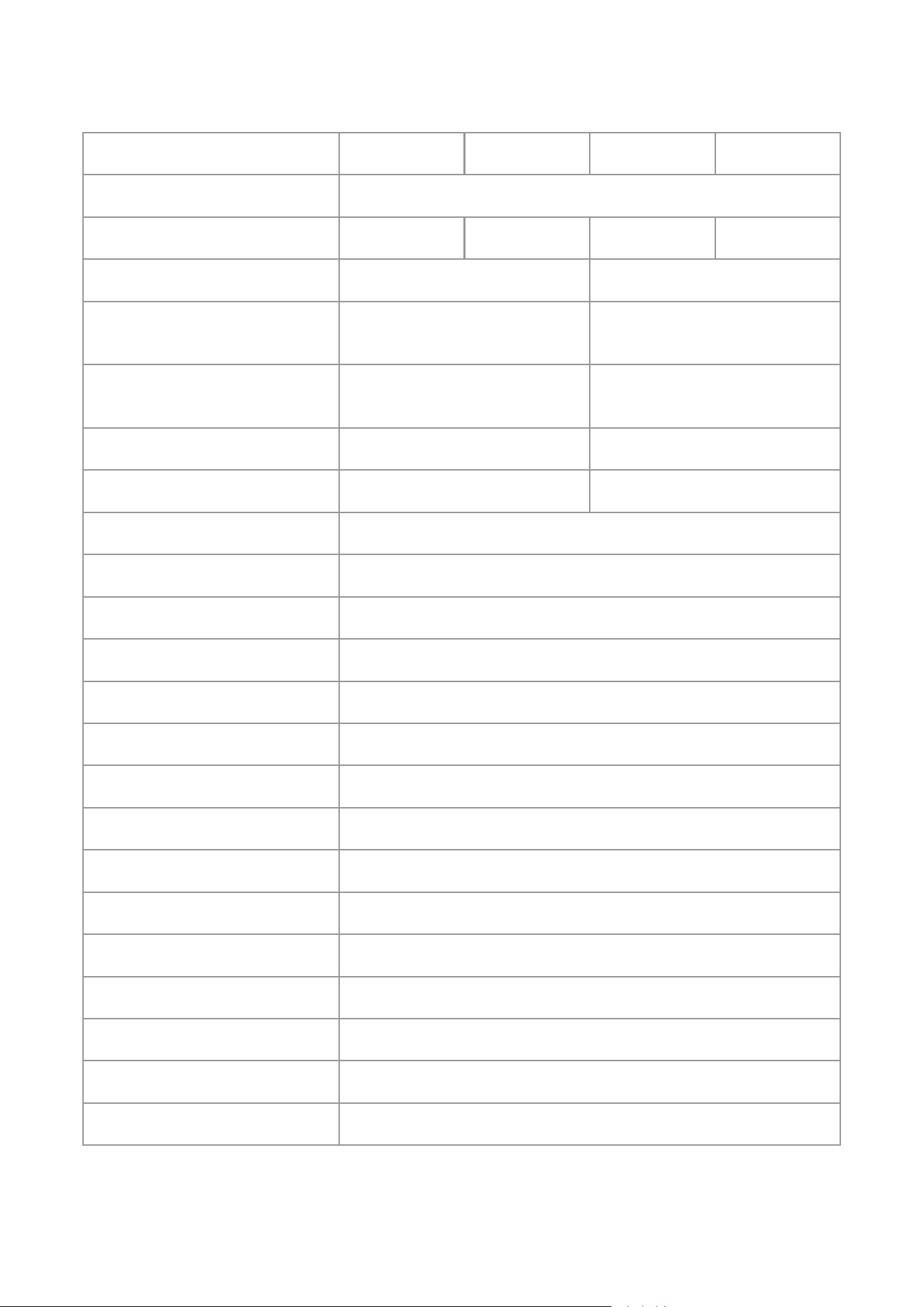
Specifications
Rev B 10/01/2024
Amplier Compability
Model
RTI-AMP Series
0-40°C
(32-104°F)
240 x 240 pixels
Plasc (ABS-PC)
Power to the RJ45 Ethernet port on the rear of device using a category 5e cable
(or faster STP) with the use of a standard PoE switch, or PoE injector
100m (328)
27.72mm x 27.72mm
RGB, Transmissive / Normally Black
Pre-galvanized steel
6 sengs available: 30 secs, 2 mins, 5 mins, 15 mins, 30 mins, 60 mins
IP 30
768.4sqmm
High gloss polished transparent acrylic
PoE Class 1 / 3.84 Wmax
RJ45, RTI-AMP proprietary over CAT 5e (or faster STP)
2 Years
Mounng Holes, Distance (Center to
Center)
External Dimensions (H x W)
86.79 x 86.79mm
(3.42 x 3.42in)
White
(RAL9003)
RTI-AMP-IWC-W-EU
23.7mm
(0.93in)
42.8mm
(1.68in)
60 mm
(2.36in)
120g (4.2oz.) 120g (4.2oz.)
83.5mm
(3.29in)
42.8mm
(1.68in)
23.1mm
(0.91in)
White
(RAL9003)
RTI-AMP-IWC-W
Black
(RAL9005)
RTI-AMP-IWC-B-EU
Black
(RAL9005)
RTI-AMP-IWC-B
115.1 x 70.6mm
(4.53 x 2.78in)
External Dimensions, Depth [From rear
side of mounng plate to outer side of
shield box]
External Dimensions, Depth [From p
of rotary encoder dial to outer side of
shield box]
Operang Temperature Range
Display Screen Resoluon
Exterior & Mechanical Parts Material
Power Supply
Maximum Cable Length
(CAT 5e)
Colour
Weight
Display Screen Area
(excluding black border)
Display Screen Dimension
(excluding black border)
Display Screen Type
Base Construcon & Shield Material
Standby Modes
IP Rang
Display Screen Material
Power Consumpon
Connecon & Data Protocol
Warranty Period
19/19
AVPro Global Holdings, LLC
2222 E 52nd Street N
Sioux Falls, SD 57104
www.avproglobal.com
© 2026 AVPro Global Holdings, LLC. All rights reserved.