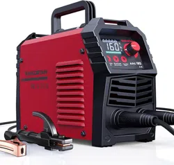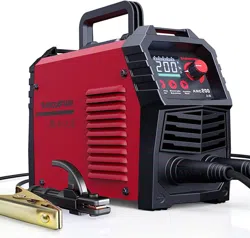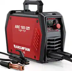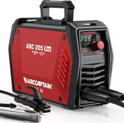
Inverter Welding Machine
ARC165/ARC205 Pro
User Manual
www.arccaptain.com

Dear Valued Customer,
Thank you for going with ARCCAPTAIN! We're all about making welders superior for you.
ARCCAPTAIN was built by high quality components, every single unit machine was passed
multiple industry leading laboratory tests to provide a great welding experience and
performance.
Two-year warranty service is provide to yours! When unpacking, make sure that the
product is intact and undamaged. DO NOT return directly before contact our customer
service.
Six ways to connect us and join in ARCCAPTAIN Community:
Email: [email protected]
Online: www.arccaptain.com/pages/contact-us
Facebook: arccaptainwelder
Instagram: arccaptain_welder
Youtube: arccaptain-weld
Whatsapp: +19892449456
This manual is designed to help you get the most out of your ARCCAPTAIN products.
Please save this manual and take time to read the safety warnings and precautions,
assembly, operating, inspection, maintenance. They will help you protect yourself against
potential hazards on the worksite. Failure to do so can result in serious injury!
www.arccaptain.com
Save for future reference:
Product
:
Date Purchased:
Serial Number:
Product Feedback:

User Manual
1. SAFETY ----------------------------------------------------------------------------------------------------------------------1
1.1 General Safety -----------------------------------------------------------------------------------------------------1
1.2 Electrical Safety ---------------------------------------------------------------------------------------------------1
1.3 Fire Safety ---------------------------------------------------------------------------------------------------------- 2
1.4 Fumes and Gases Safety ----------------------------------------------------------------------------------------2
1.5 Arc Rays and Noice Safety ------------------------------------------------------------------------------------- 2
1.6 Gas Shielded Welding – Cylinder Safety --------------------------------------------------------------------3
1.7 Additional Safety Information -------------------------------------------------------------------------------- 3
2. PRODUCT DESCRIPTION -----------------------------------------------------------------------------------------------3
2.1 Product Overview ------------------------------------------------------------------------------------------------ 3
2.2 Packge ---------------------------------------------------------------------------------------------------------------4
2.3 Technical Parameters ------------------------------------------------------------------------------------------- 5
3. OPERATION AND INSTRUCTIONS -----------------------------------------------------------------------------------5
3.1 Panel of ARC165/ARC205 Pro ---------------------------------------------------------------------------------6
3.2 Control Panel ------------------------------------------------------------------------------------------------------ 7
3.3 Fault Code Table --------------------------------------------------------------------------------------------------8
3.4 Nameplate: ---------------------------------------------------------------------------------------------------------8
3.5 Press The Key Combination To Display The Code Table ----------------------------------------------10
4. INSTALLATION AND CONNECTION ------------------------------------------------------------------------------- 10
4.1 Installation --------------------------------------------------------------------------------------------------------10
4.2 Input Power Connection --------------------------------------------------------------------------------------12
5. OPERATION --------------------------------------------------------------------------------------------------------------13
5.1 MMA WELDING MODE(NON-SYN) -------------------------------------------------------------------------13
5.2 MMA Welding Mode(SYN) ----------------------------------------------------------------------------------- 14
5.3 Welding Parameters Table -----------------------------------------------------------------------------------14
6. OPERATION FOR LIFT TIG --------------------------------------------------------------------------------------------14
6.1 LIFT TIG Welder Cable Connection -------------------------------------------------------------------------15
6.2 LIFT TIG Welder Operation -----------------------------------------------------------------------------------17
6.3 LIFT TIG Welding Mode --------------------------------------------------------------------------------------- 19
6.4 LIFT TIG Welding Parameters Table ----------------------------------------------------------------------- 19
7. Strap Installation ------------------------------------------------------------------------------------------------------ 19
8. BASIC KNOWLEDGE OF WELDING -------------------------------------------------------------------------------- 20
8.1 Welding Process Of MMA ------------------------------------------------------------------------------------ 20
8.2 Tools For MMA --------------------------------------------------------------------------------------------------21
8.3 Basic Operation Of MMA ------------------------------------------------------------------------------------- 21
9. TROUBLESHOOTING -------------------------------------------------------------------------------------------------- 24
10. MAINTENANCE ------------------------------------------------------------------------------------------------------- 25
1
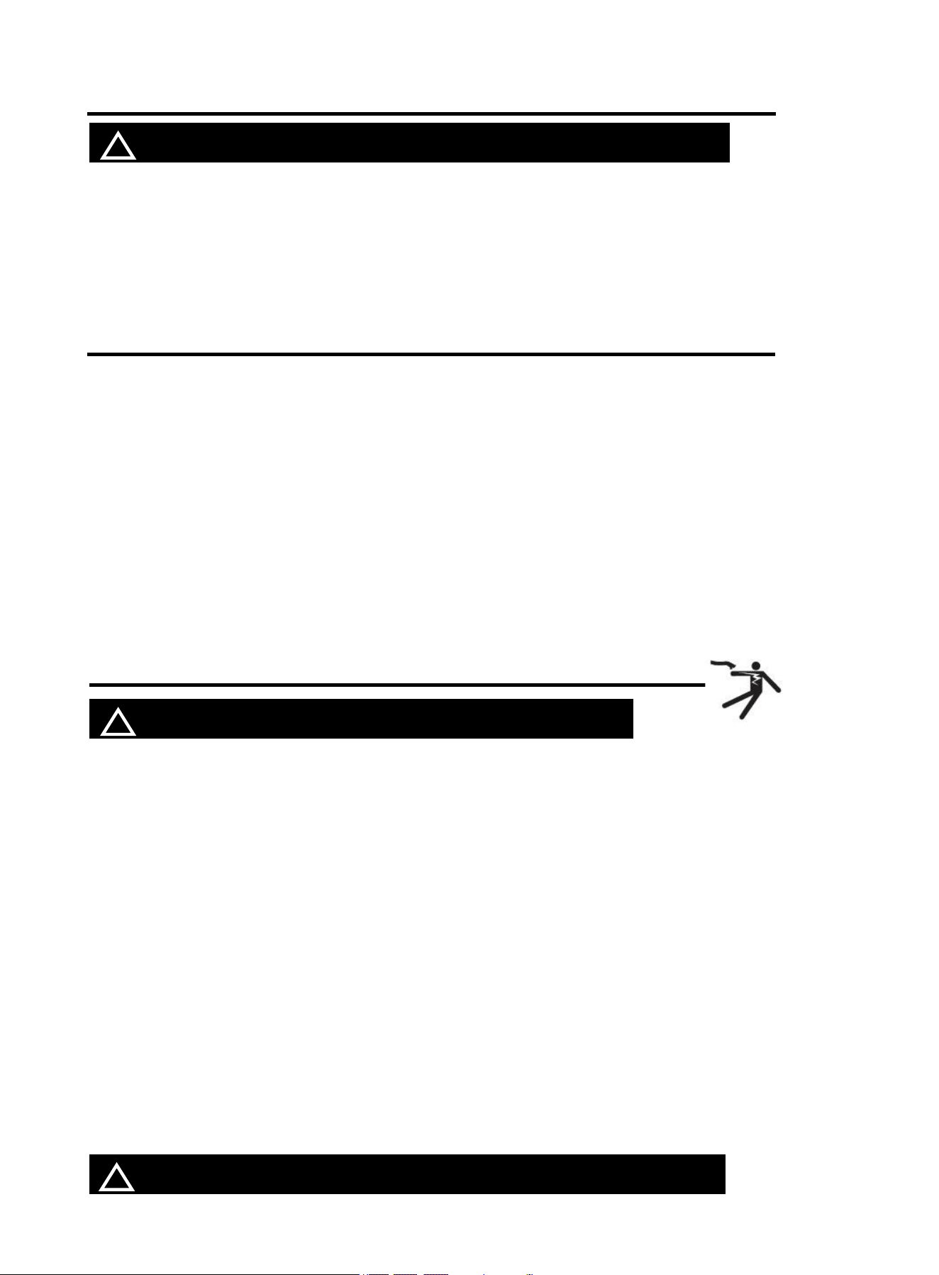
1. SAFETY
! WARINING READ ALL SAFETY WARNINGS BEFORE WORKING!
Failure to follow the warnings and instructions may result in electric shock, fire and/or serious
injury. Save all warnings and instructions for future reference!
If you encounter any issues during installation or operation, refer to the relevant sections in this manual
for inspection. If you're still unsure or unable to resolve the problem, please contact ARCCAPTAIN
professional support.
1.1 General Safety
Do NOT use the welder if the switch does not turn it on and off.
Disconnect the plug from the power source before making any adjustments, changing
accessories, or storing the welder.
Ensure the switch is off before connecting to power or moving the welder to prevent
accidental starting.
Always maintain and use safety guards, covers, and devices properly.
Keep hands, hair, clothing, and tools away from moving parts like V-belts, gears, and fans.
Follow these instructions and consider working conditions when using the welder and
accessories.
This manual may not cover every possible situation. It's important for the operator to use
common sense and caution while using this product.
1.2 Electrical Safety
! WARINING BEWARE OF ELECTRIC SHOCK!
DO NOT weld in a damp area or come in contact with a moist or wet surface.
DO NOT modify any wiring, ground connections, switches, or fuses in this welding
equipment.
DO NOT come into physical contact with any part of the welding current circuit, including the
workpiece, ground clamp, electrode or welding wire, and metal parts on the electrode holder
or MIG gun.
DO NOT connect the ground clamp to electrical conduit, and DO NOT weld on electrical
conduit.
NEVER leave the Welder unattended while energized. Turn off the power if you have to leave.
DO NOT attempt to plug the welder into the power source if the ground prong on INPUT
POWER CABLE plug is bent over, broken off, or missing.
DO NOT alter INPUT POWER CABLE or plug in any way.
People with pacemakers should consult their physicians before use. Magnetic field can
make cardiac pacemaker a bit wonky.
! WARINING REPLACING COMPONENTS CAN BE DANGEROUS!
2
Only experts should replace machine parts. Avoid dropping foreign objects into the machine
during component replacement. Ensure correct wire connections after replacing PCBs to
prevent property damage.
1.3 Fire Safety
! WARINING BEWARE OF FIRE HAZARD!
Place the machine on non-combustible surfaces to prevent fires.
Ensure no flammable materials are near the working area to reduce fire risk.
Avoid installing the machine near water sources to prevent water damage.
Always weld/cut materials in a dry environment with humidity below 90% and maintain a
working temperature between -10°C and 40°C.
When welding/cutting outdoors, ensure shelter from sunlight and rain, keeping the machine
dry at all times.
Do not operate the machine in dusty or chemically corrosive environments.
Remove or secure all combustible materials within a 35 feet (10 meters) radius of the work
area. Use fire-resistant material to cover or seal open doorways, windows, cracks, and other
openings.
Improper use can lead to fire or explosion. Avoid flammable materials near the working area,
keep a fire extinguisher nearby with trained personnel, refrain from cutting closed
containers, and do not use the machine for pipe thawing.
1.4 Fumes and Gases Safety
! WARINING SMOKE CAN BE HARMFUL TO YOUR HEALTH!
Keep your head away from the smoke while cutting to avoid breathing in harmful gases.
Ensure the working area is well-ventilated with exhaust or ventilation equipment during
cutting.
Only work in a confined area if it's well-ventilated, or wear an air-supplied respirator.
1.5 Arc Rays and Noice Safety
! WARINING
Arc radiation can harm eyes and skin; excessive noise can damage hearing.
Use certified welding eye protection with at least a number 10 shade lens rating.
Wear leather leggings and fire-resistant shoes or boots; avoid clothing that can catch sparks
or molten metal. Do not touch hot workpiece with bare hands.
Keep clothing free of flammable substances and wear dry, insulating gloves and protective
clothing.
Wear an approved head covering and use appropriate welding attire.
EXCESSIVE NOISE DOES GREAT HARM TO HEARING!
ARC RADIATION MAY HURT YOUR EYES AND BURN YOUR SKIN!

3
When welding overhead or in confined spaces, use flame-resistant ear plugs or ear muffs.
Wear ear covers or other hearing protectors when cutting.
1.6 Gas Shielded Welding – Cylinder Safety
! WARINING CYLINDERS CAN EXPLODE WHEN DAMAGED!
Never weld on a pressurized or closed cylinder.
Avoid letting the electrode holder, electrode, welding torch, or welding wire touch the
cylinder.
Keep cylinders away from all electrical circuits, including welding circuits.
Always keep the protective cap on the valve except when the cylinder is in use.
Use only the correct gas shielding equipment designed for your specific type of welding, and
maintain it properly.
Protect gas cylinders from heat, physical damage, slag, flames, sparks, and arcs.
Always follow proper procedures when moving cylinders.
Do not install the machine in an environment with explosive gas to avoid an explosion.
1.7 Additional Safety Information
Use only the supplied power cord for this welder or an identical replacement cord. Do not
install a thinner or longer cord on this Welder.
Maintain labels and nameplates on the Welder. These carry important information.
Ensure the ground clamp is securely connected to the workpiece during welding.
Pressing the gun switch when welding or cutting.
When disposing of the cutting machine, please note the following:
Burning electrolytic capacitors on the main circuit or PCB board may cause explosions.
Burning plastic components such as the front panel may produce toxic gases. Dispose of it
as industrial waste.
2. PRODUCT DESCRIPTION
2.1 Product Overview
This is a new professional series MMA Welder with advanced technology, complete functions and
excellent performance. This ultra-portable welding system is suitable for a variety of application needs.
In addition, the new series also includes the latest remote control via APP.
MCU digital control achieves intelligent synergy
Latest IGBT Inverter Technology
LED display screen for easy operation
High output no-load voltage, available for cellulose electrode (for ARC205 only )
Smart cooling fan, excellent heat dissipation
Compact and portable with light weight
MMA Synergic Control (SYN): ARC 165/205 Pro welders can automatically identify the type of
electrode being used and optimise the corresponding welding parameters. Simplifying complexity
makes the welding process more comfortable and easier for the operator to control.
4
Lift TIG argon arc welding(TIG):When connecting the optional arc welding TIG torch, gas regulator
and gas cylinder, the Arc 165/205 Pro becomes a TIG welding machine.
Hot Start: Automatically increasing the current when starting welding, it ensures rapid generation of
a stable arc and improves welding starting quality.
Arc Force: In high-impedance conditions, such as short arc welding, by additionally increasing the
welding current, the arc is prevented from extinguishing and ensuring a more stable welding
process.
Anti-stick Feature: The machine continuously outputs low current (usually 10A), making the stuck
welding rod easy to detach.
VRD (Voltage Reduction Device): Reduces the risk of electric shock for operator safety.
Dual voltage 120V/240V.
IP21S: Can be protected from solid and vertical dripping water larger than 12.5mm in places without
internal circulation cooling, ensuring a stable and safe working environment.
Multiple Protection Functions: Effectively prevent damage caused by overheating, overcurrent or
undervoltage of components during operation, ensuring stable operation and service life of the
equipment.
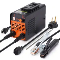
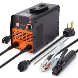
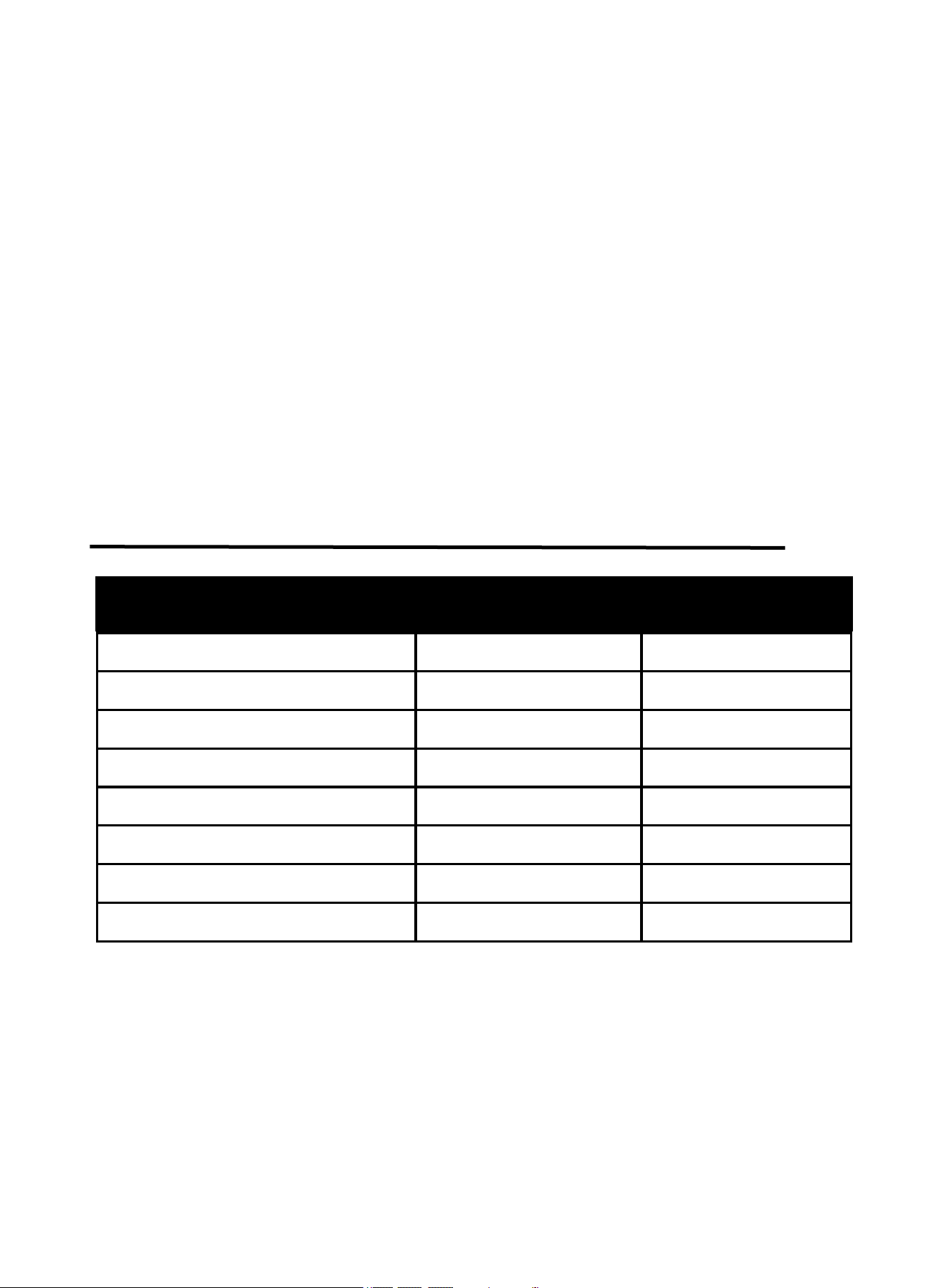
2.2 Packge
Name
Specification
Quantity (pcs)
Welding machine
ARC Pro
1
Electrode Holder
10ft
1
Ground Clamp
10ft
1
Adapter
240V to 120V
1
Shoulder Strap
/
1
Wire Brush
/
1
Welding Rod
E6013
/
Operator’s manual
For ARC PRO
1
5
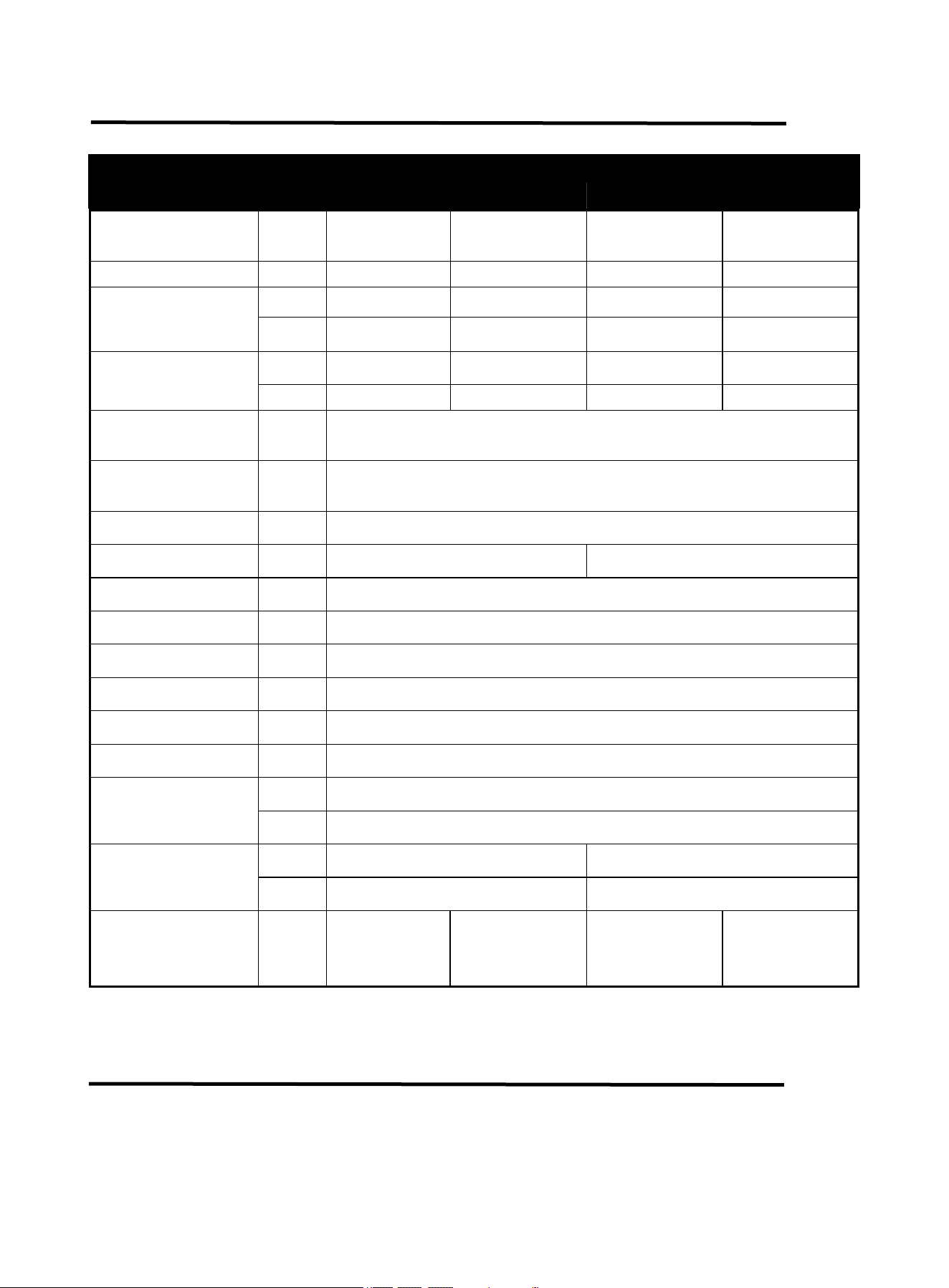
2.3 Technical Parameters
TECHNICAL
PARAMETERS
Units
Model
ARC165 Pro
ARC205 Pro
Rated input
voltage
V
AC120V±15%
50/60HZ
AC240V±15%
50/60HZ
AC120V±15%
50/60HZ
AC240V±15%
50/60HZ
Rated input power
kVA
5
7.1
6
9.4
Welding current
range(MMA)
A
20-105
20-165
20-150
20-205
V
20.8-24.2
20.8-26.6
20.8-26.0
20.8-28.2
Welding current
range(TIG)
A
20-105
20-165
20-150
20-205
V
10.8-14.2
10.8-26.6
10.8-16.0
10.8-18.2
Hot start current
range
A
0~60A
ARC force current
range
A
0~100A
Rated duty cycle
-
60%
No-load voltage
V
76
85
VRD voltage
V
12
Overall efficiency
-
80%
Protection grade
-
IP21S
Power factor
-
COSφ=0.7
Insulation grade
-
H
Standard
-
ANSI/NEMA/IEC 60974-1
Dimensions
L*W*H
Inch
12.88*5.05*8.4
mm
327*128*213mm
Net weight
Lb
6.80
8.30
KG
3.08
3.76
Applicable
electrode
Inch
/
mm
1/16"-3/25"
1.6-2.5
1/16"-1/8"
1.6-3.2
1/16"-1/8"
1.6-3.2
1/16"-5/32"
1.6-4.0
3. OPERATION AND INSTRUCTIONS
6
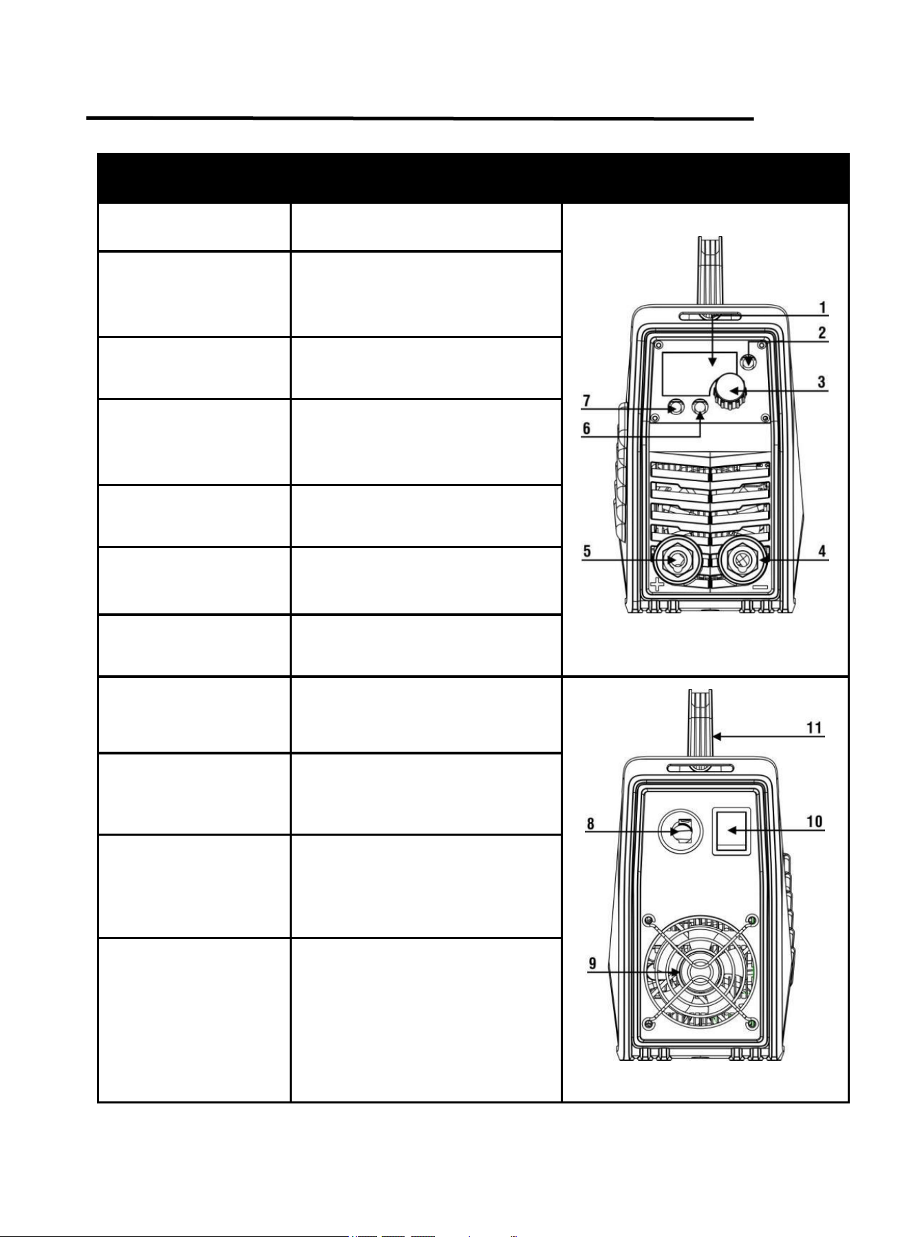
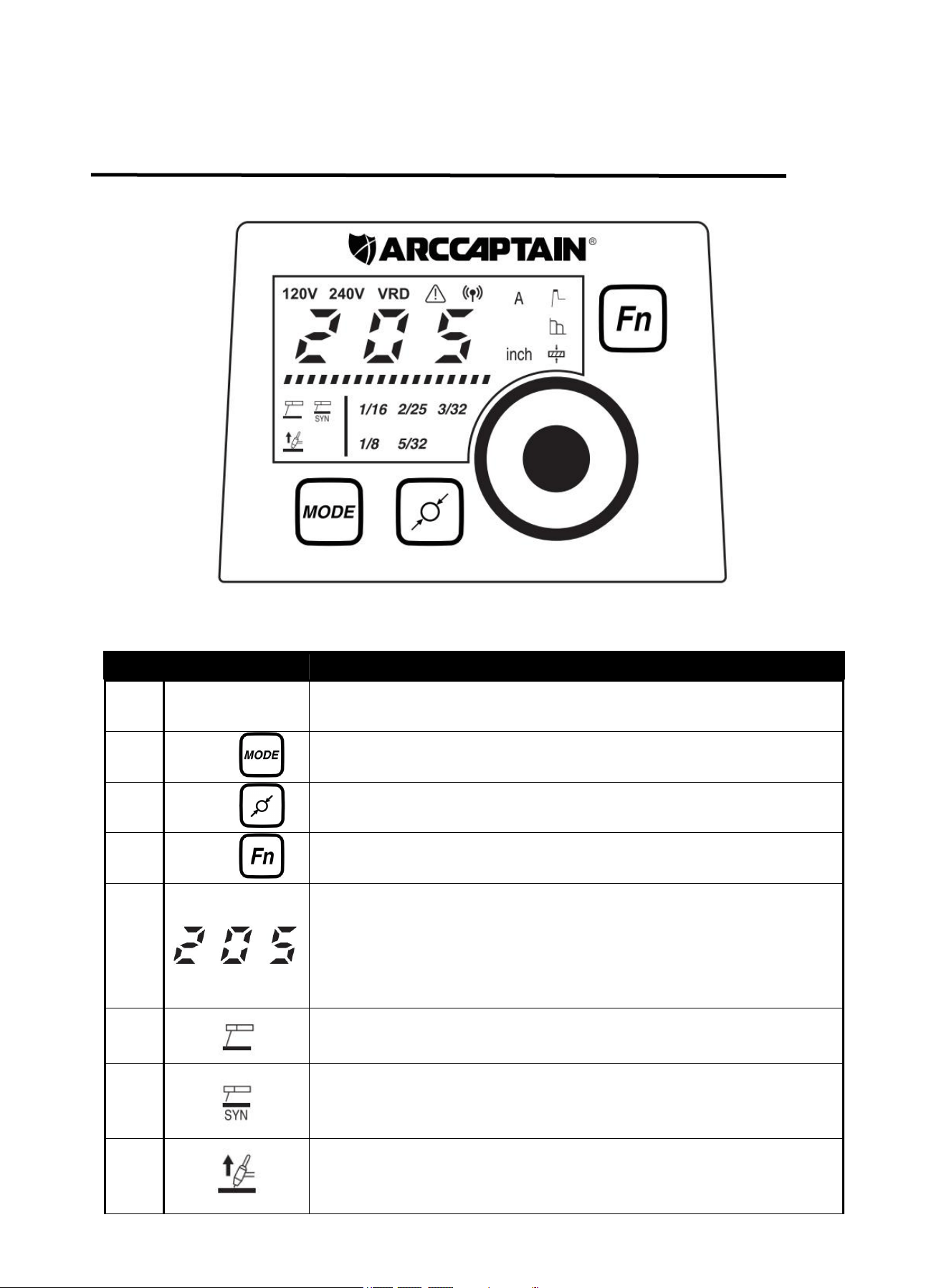
3.1 Panel of ARC165/ARC205 Pro
Part name
Function
Picture
1. Digital screen
To display the welding information
Figure 1 Front panel controls
2. Function button
For Welding/Hot start/Arc force
current and workpiece thickness
conversion.(For MMA mode only)
3. Parameter
adjustment knob
Rotate the knob to adjust the
parameters
4. Output “-” terminal
To connect the welding
torch/Electrode Holder/Ground
Clamp
5. Output “+” terminal
To connect the Ground
Clamp/Electrode Holder
6. Electrode diameter
button
For electrode diameter conversion.
(For MMA Synergy Mode only)
7. Welding mode
button
For MMA/MMA Synergy/Lift-TIG
welding mode conversion
8. Power wire
For power supply input
Figure 2 Back panel controls
9. Cooling fan
For heat dissipation through forced
air cooling
10. Power switch
To control the ON/OFF of the input
power of the machine
11. Handle
For translation and storage
7
3.2 Control Panel
Figure 3
No.
Part name
Function
1
Parameter
adjustment knob
Rotate the knob to adjust the parameters.
2
Button “ ”
For MMA/MMA Synergy/Lift-TIG welding mode conversion.
3
Button “ ”
For electrode diameter “1/16 2/25 3/32 1/8 5/32” conversion.(For SYN
mode only )
4
Button “ ”
For Welding/Hot start/Arc force current and workpiece thickness
conversion.(For MMA mode only)
5
1.Displays the value of the current parameter.
2.If there is no operation after 3 seconds,it will automatically display
the value of the setting welding current.
3.When the product is not working correctly, an error code is
displayed.
6
If the indicator is on, it indicates the MMA mode is selected.
7
If the indicator is on, it indicates the MMA Synergy mode is selected.
8
If the indicator is on, it indicates the Lift-TIG mode is selected.
8
*For more detailed information about the connection and operational guidelines for the
ARCCAPTAIN APP, please visit arccaptain.com and explore the resources available there.
3.3 Fault Code Table
Digital tube display code
Code meaning
E-60
overheat protection
E-10
over-current protection
E-34
15V undervoltage protection
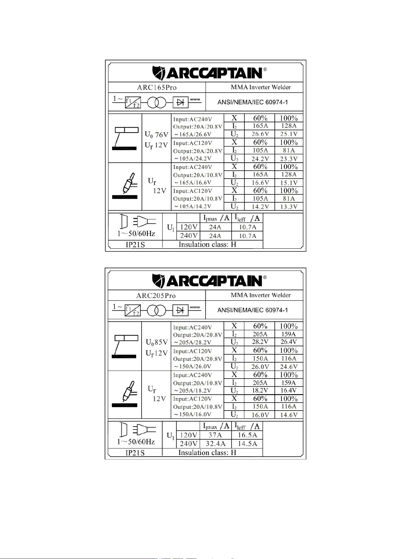
3.4 Nameplate:
On the machine, there is a plate that includes all the operating specifications for your new unit. The serial
number of the product is also found on this plate.
The duty cycle rating of a welder defines how long the operator can weld and how long the welder must
rest and be cooled. Duty cycle is expressed as a percentage of 10 minutes and represents the maximum
welding time allowed. The balance of the 10-minute cycle is required for cooling.
For example, a welder has a duty cycle rating of 60% at the rated output of 165A/205A. This means with
that machine: you can weld at 165A/205A output for six (6) minutes out of 10 with the remaining four (4)
9
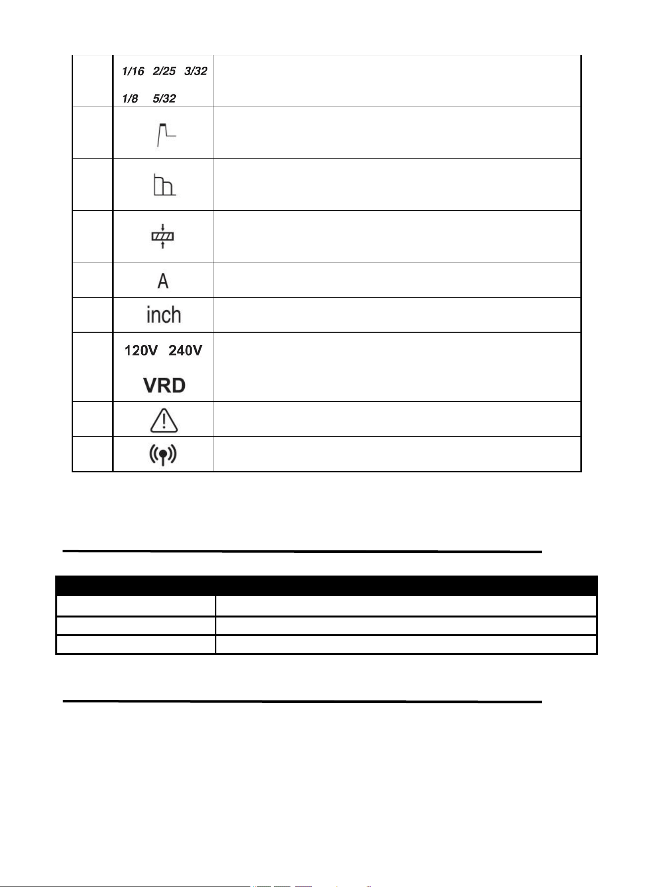
MMA synergic electrode diameter selecting indicator.
10
MMA hot start adjusting indicator. When it is blinking, hot start current
can be set at present.
11
MMA arc-force adjusting indicator. When it is blinking, arc-force
current can be set at present.
12
MMA Workpiece Thickness Indicator. The welding current can be
automatically set to match the selected workpiece thickness.
13
Unit of current.
14
Unit of workpiece thickness.
15
The input voltage is AC120V/240V
16
The VRD function is on when it is blinking.
17
The machine is on alarm state when it is blinking.
18*
The machine is connected to wireless.
9
minutes required for cooling. The duty cycle of your new welder can be found on the data plate affixed to
the machine. It looks like the diagram below.
Figure 4
Figure 5
10
The following operation requires sufficient professional knowledge on
electric aspect and comprehensive safety knowledge. Operators should be
holders of valid qualification certificates which can prove their skills and
knowledge. Make sure the input cable of the machine is disconnected from
the electricity utility before uncovering the welding machine.
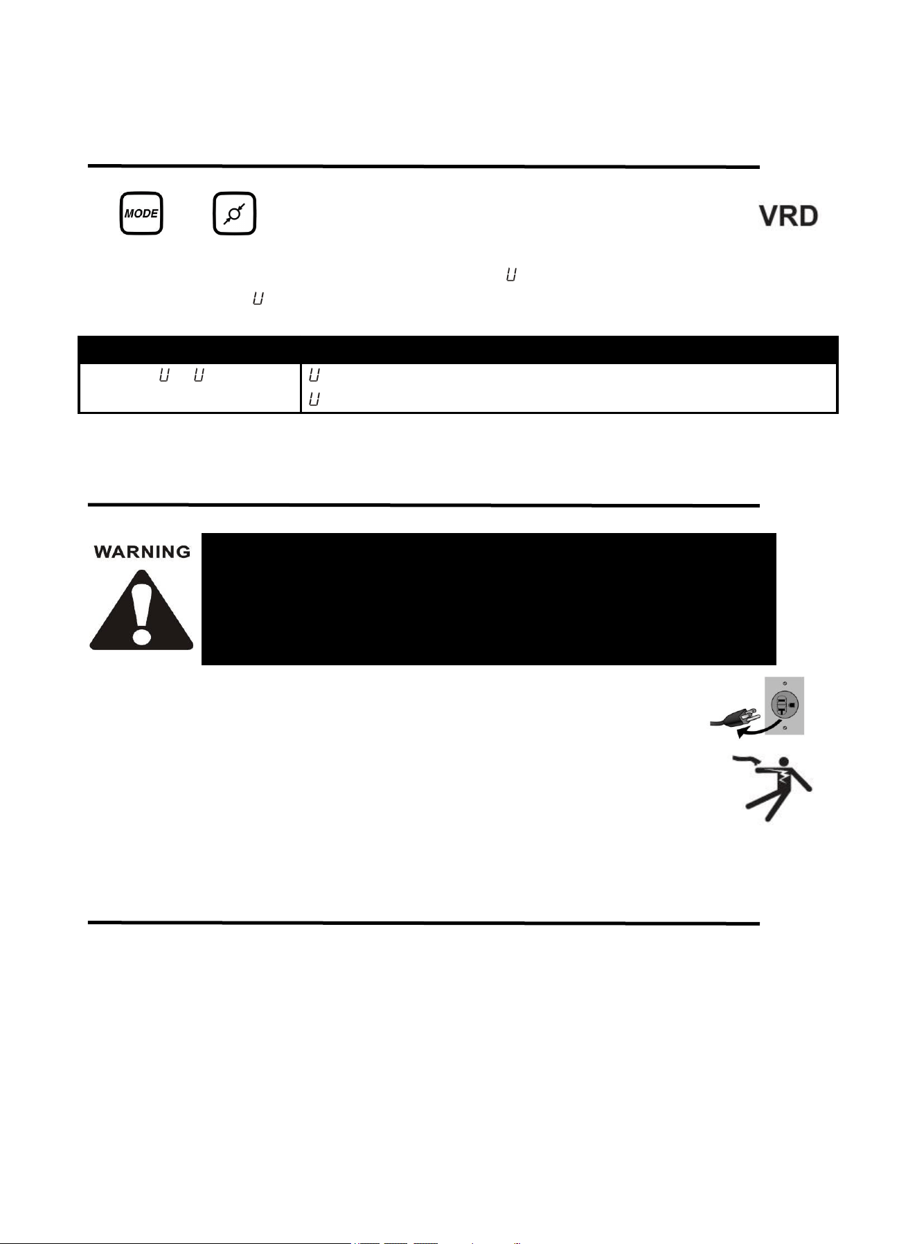
3.5 Press The Key Combination To Display The Code Table
Combination key for switching VRD on or off:
and buttons are pressed simultaneously to switch on or off MMA VRD .
Under MMA, VRD is not available by default, but it is available when welding Mode and Electrode
Selection buttons are pressed simultaneously for 3s with -1 display. And VRD is unavailable if press
them for 3s again with -0 display.
Digital tube display code
Code meaning
-0 / -1
-0: The machine has exited VRD state.
-1: The machine has gone into VRD state.
4.INSTALLATION AND CONNECTION
Note:
Turn off the power supply switch before any electric connection operation.
The housing protection grade of this machine is IP21S, so do not use it in rain.
Place the Welder on a level surface that can bear its weight near the work area.
4.1 Installation
Please install the machine strictly according to the following steps.(check page 11)
11
Description
Picture
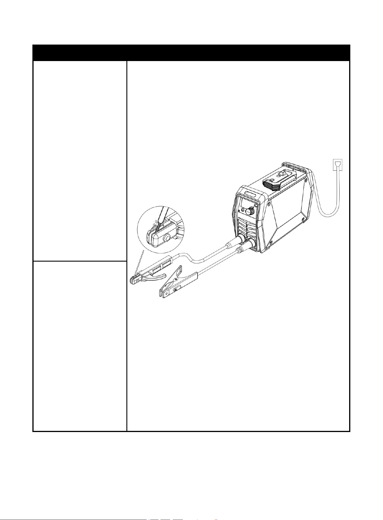
1. Insert the cable plug with
electrode holder into
the “+” socket on the
front panel of the
welding machine, and
tighten it clockwise.
NOTICE
:
The holder connector
MUST be tightly
connected to the
socket to avoid
power short circuit.
Set Electrode Holder
down on
nonconductive,
nonflammable
surface away from
any grounded
objects.
Figure 6 DCEP Schematic Diagram of MMA Welding
2. Insert the cable plug with
ground clamp into the
“
-
” socket on the front
panel of the welding
machine, and tighten it
clockwise.
NOTICE:
The ground clamp
connector MUST be
tightly connected to
the socket to avoid
power short circuit.
Ensure the ground
clamp is connected
on clean, bare metal
(not rusty or painted)
DCEP
12
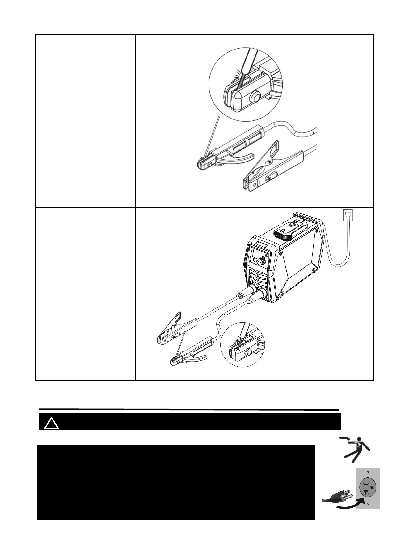
3. Place the bare metal
end of the Stick
Electrode inside the
jaws of the Electrode
Holder.
NOTICE:
Ensure that the clip is
on the conductive side of
the electrode. Ensure that
it is securely clamped.
Figure 7
4. When you use Alkaline
rods (E7018), need to
DCEP, that is connect
the holder and ground
clamp as mentioned
above in above 1. and 2.
5. If you use Acidic
rods(E6013), need to
DCEN, that is connect
the holder to “-”and
ground clamp to “+” .
NOTICE:
Incorrect connecting
can affect welding
results.
Figure 8 DCEN Schematic Diagram of MMA Welding
4.2 Input Power Connection
! WARINING BEWARE OF ELECTRIC SHOCK!
NOTICE: The following steps require applying power to the Welder
with the cover open.
To prevent serious injury from fire or electric shock:
1. DO NOT touch anything, especially not the ground clamp, with the
gun or welding wire or an arc will be ignited.
2. DO NOT touch internal Welder Components while it is plugged in.
DCEN
13
The ARC165 /ARC205 Pro operates with a 120V OR 240V power supply.
Turn the Power Switch to the OFF position, then plug the Welder into a properly grounded 240V
receptacle that matches the plug. Use the included 120V power adaptor if plugging the Welder into
a 120V receptacle.
Plug the Power Cord into a properly grounded. Set Electrode holder down on nonconductive,
nonflammable surface away from any grounded objects. And then turn the Power Switch ON.
NOTE:
For optimal performance, connect the ARC165/ARC205 Pro to a 40A branch circuit. If
connected to a circuit with lower capacity, expect reduced welding current and duty cycle.The
circuit must be equipped over 40A with delayed action-type circuit breaker or fuse.
5. OPERATION
! WARINING BEWARE OF ELECTRIC SHOCK!
5.1 MMA WELDING MODE(NON-SYN)
MMA NON-SYN Welding Mode allows to independently adjust the Current, Workpiece Thickness,Arc
Force, and Hot Start parameters as needed.(Beginners should use the SYN function. Refer to
section 5.2 for more details.)
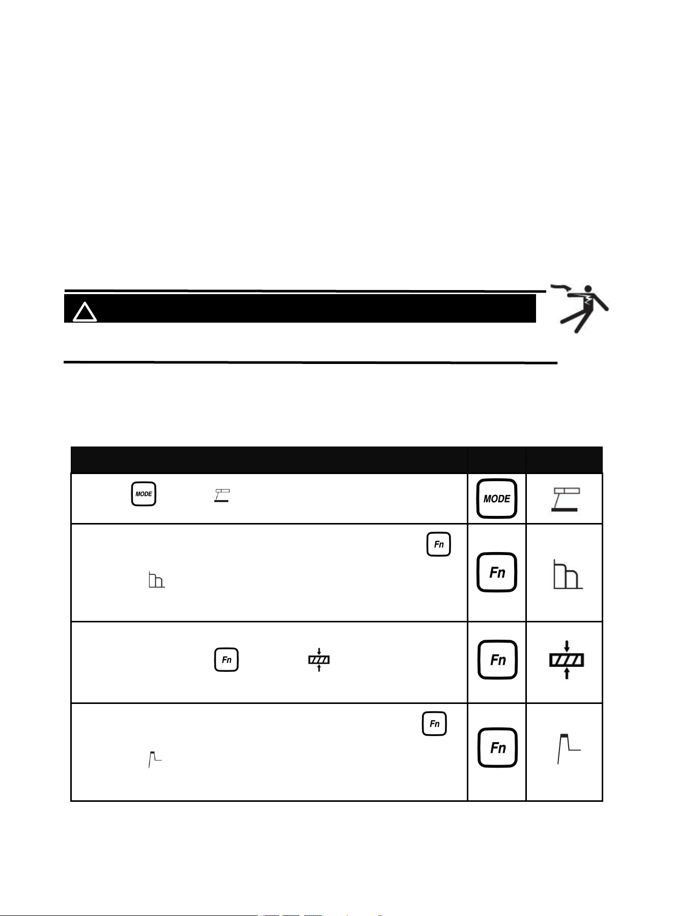
Describe
Part
Select
1. Press " " , select , rotate the knob to adjust the current.
2. Adjustable Arc Force in MMA non-SYN welding mode.Press " ",
select , rotate the knob to adjust the Arc Force current.
Adjustment range is 0-100 amps.
3. In MMA non-SYN welding mode, the workpiece thickness can be
adjusted. Press the " ", select the , and rotate the knob to
adjust the workpiece thickness.
4. Adjustable Hot Start in MMA non-SYN welding mode.Press " " ,
select , rotate the knob to adjust the Hot Strat current.
Adjustment range is 0-60 amps.
If there is any other question about the installation meeting applicable electrical code requirements,
consult a qualified electrician.
14
The following operation requires sufficient professional knowledge on
electric aspect and comprehensive safety knowledge. Operators should be
holders of valid qualification certificates which can prove their skills and
knowledge. Make sure the input cable of the machine is disconnected from
the electricity utility before uncovering the welding machine.
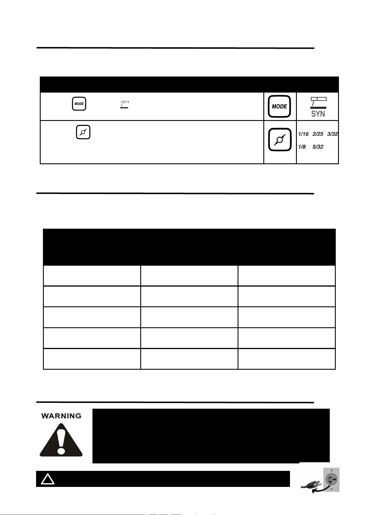
5.2 MMA Welding Mode(SYN)
MMA SYN WELDING MODE allow the welder to automatically identify the type of electrode used and
optimize the corresponding welding parameters.(This function is suitable for beginners)
Describe
Part
Select
1.Press " " , select , rotate the knob to adjust the current.
2.Press " ", select the welding rod size, and the welder will
automatically match the current.
5.3 Welding Parameters Table
Note: This table is suitable for mild steel welding. For other materials, consult related materials
and welding process for reference.
6. OPERATION FOR LIFT TIG
! WARINING DO NOT set up without SWITCH OFF !
Electrode Diameter
mm(inch)
Plate thickness
mm
(inch)
Recommended Welding
Current(A)
1.6mm
1/16
1~2.5mm
0.04~0.11
30~65
2mm
2/25
2.3~4mm
0.09~0.16
49~94
2.4mm
3/32
3.5~4.5mm
0.14~0.18
78~123
3.2mm
1/8
4.8~8.3mm
0.19~0.33
99~177
4.0mm
5/32
8.6~10mm
0.34~0.39
178~205
15
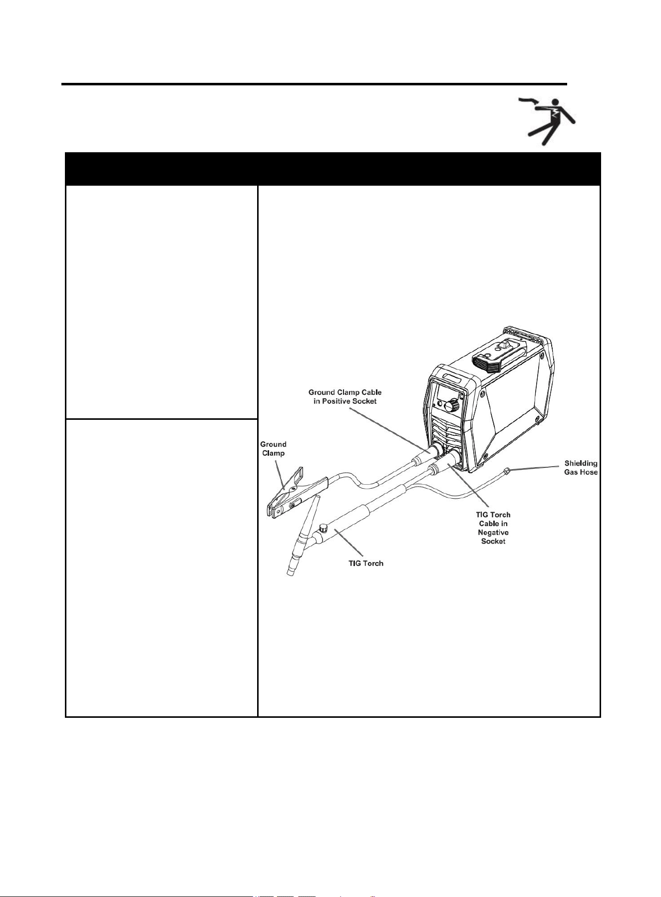
6.1 LIFT TIG Welder Cable Connection
NOTICE: Before setting up or using this product for new function,
make sure to read the entire Important Safety Information section at
the beginning of this manual!
Description
Picture
Step 1: Connect cables.
1. Insert the ground clamp cable
into the positive socket and twist it
all the way clockwise to lock it in
place.
NOTICE:
The ground clamp
connector MUST be tightly
connected to the socket to
avoid power short circuit.
Ensure the ground clamp is
connected on clean, bare
metal (not rusty or painted)
Figure 9
2. Plug the Lift-TIG torch cable
into the negative socket and twist it
clockwise to lock it in place.
3. For instructions on connecting a
shielded gas hose, refer to the
'Connecting Shielded Gas' section
on the following page.
NOTICE:
TheLift-TIG torch cable
MUST be tightly connected
to the socket to avoid power
short circuit.
Set Lift-TIG torch cable down
on nonconductive,
nonflammable surface away
from any grounded objects.
16
More information:
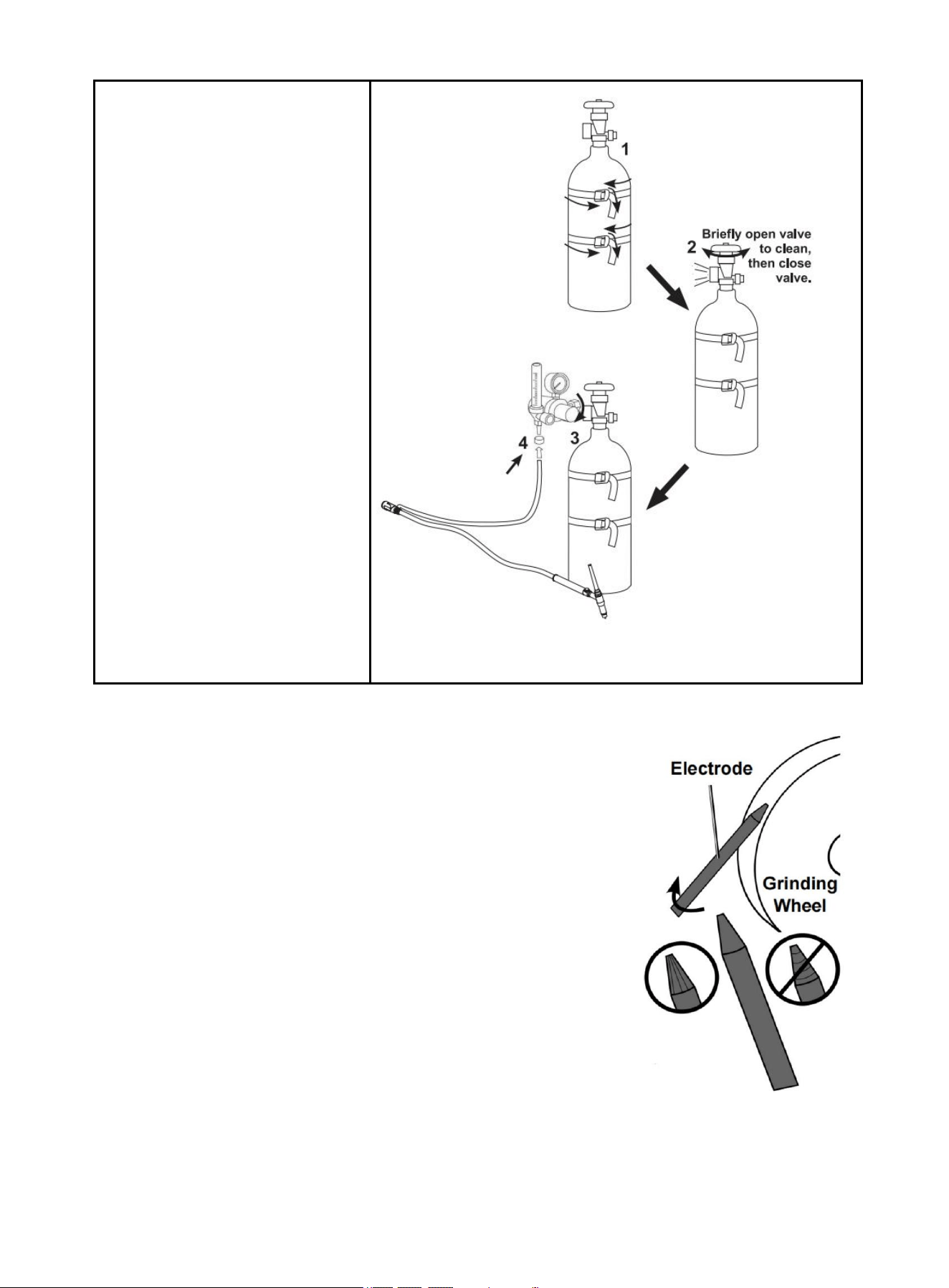
Sharpen tungsten Electrode
To avoid Electrode contamination, dedicate a fine grit grinding wheel
exclusively to Electrode grinding.
1. Shut off the welder and wait until Electrode and Torch have cooled
enough to handle.
2. Remove Back Cap to release Collet’s grip on Electrode.
3. Pull Electrode out from front of Torch. (Pulling it from rear will damage
Collet and create burrs on Electrode).
4. If Electrode has dulled or been otherwise contaminated, use pliers or
a suitable tool to grip the Electrode above the contaminated section
and snap off the end of the Electrode.
5. Lightly press Electrode tip against the surface of the grinding wheel at
an angle. Rotate Electrode tip until a blunt point is formed.
NOTE: Grinding direction must be parallel to length of Electrode.
6. The conical portion of the ideal tip will be 2-1/2 times as long as the
Electrode diameter.
7. Re-insert Electrode into Collet with tip protruding 1/8"-1/4" beyond the Ceramic Nozzle, then
re-tighten the Back Cap to secure the Electrode in place.
Step 2: connect Shielding gas
1.With assistance, place a 100%
Argon cylinder (not included)
onto a cabinet or cart near the
welder. Secure the cylinder in
place with two straps (not
included) to prevent tipping.
2.Remove the cylinder's cap.
Stand to the side of the valve
opening, then briefly open the
valve to blow dust and dirt
from the valve opening. Close
the cylinder valve.
3.Locate the regulator (not
included) and loosen its valve.
Thread the regulator onto the
cylinder and tighten the
connection with a wrench.
4.Connect the shielding gas hose
on the TIG torch cable
connector to the regulator's
outlet and tighten the
connection with a wrench.
Figure 10
Figure 11
17
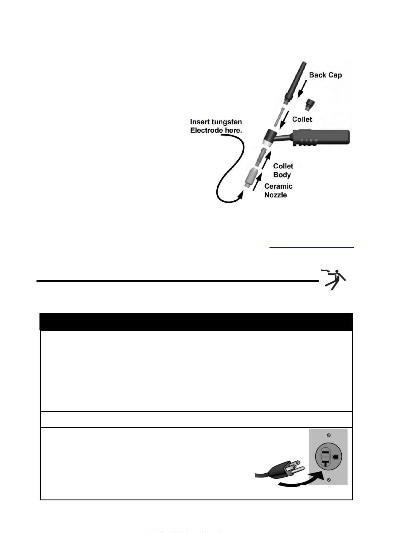
Assemble tig torch
1. Consult Settings Chart, on top of Welder, to
determine proper Tungsten Electrode size
to be used with thickness of material to be
welded.
2. Match Collet and Collet Body sizes to
Tungsten Electrode size.
3. Thread Collet Body into the front of the
Torch.
4. Make sure Ceramic Nozzle size is
appropriate for application.
5. Thread Ceramic Nozzle onto Collet Body.
6. Insert Collet into back of Torch and into
Collet Body.
7. Insert Tungsten Electrode into Collet on front
of Torch.
8. Lock Electrode in place with Back Cap. Electrode should protrude 1/8" to
1/4" beyond the Ceramic Nozzle.
NOTE: The tig torch and tungsten electrode are not included in the
machine. If you need to purchase, please log in to the official website: WWW.ARCCAPTAIN.COM
6.2 LIFT TIG Welder Operation
Lift TIG Mode: when connecting the optional arc welding TIG torch, gas regulator and gas cylinder, the
Arc 165/205 Pro becomes a TIG welding machine.
Operation step
1. Open gas cylinder’s valve all the way.
NOTE: TO PREVENT DEATH FROM ASPHYXIATION:
Do not open gas without proper ventilation. Fix gas leaks immediately. Shielding gas can
displace air and cause rapid loss of consciousness and death. Shielding gas without carbon
dioxide can be even more hazardous because asphyxiation can start without feeling
shortness of breath.
2. Set Flow Gauge to SCFH VALUE.
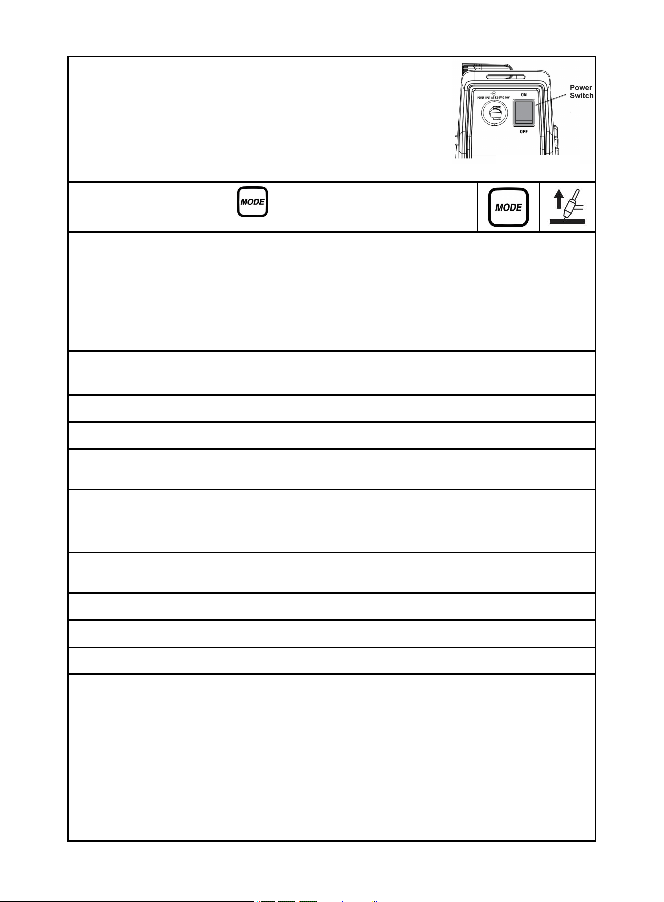
3. connect power cord.
NOTE: Turn the Power Switch off before connecting Power
Cord. Plug the Power Cord into a properly grounded and rated
receptacle that matches the plug. The circuit must be
equipped with delayed action-type circuit breaker or fuses.
Figure 12
Figure 13
18
4. Turn the Power Switch ON.
NOTE: Set TIG Torch down on nonconductive, nonflammable
surface away from any grounded objects.
The Operation interface will light up and the Cooling fan will rotate.
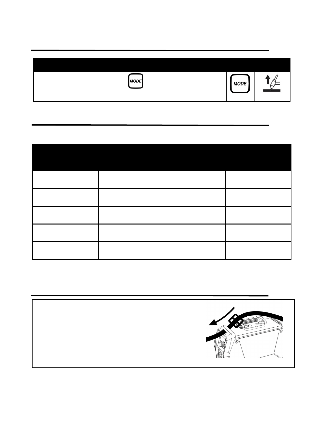
5. Press the Weld Mode button , for Lift-TIG welding mode changeover.
6. Hold TIG Torch in one hand and the TIG Rod (sold separately) in other hand. Both hands need to
wear protective gloves.
WARNING! TO PREVENT SERIOUS INJURY: Metalwork bench must be grounded when TIG
welding.
NOTE: Maintain a constant distance between the Tungsten Electrode and the workpiece: between 1
and 1.5 times the diameter of the Electrode.
7. The initial settings may need to be adjusted after stopping and carefully inspecting the weld.
Please refer to 6.4 Lift TIG Welding parameters table,Proper welding takes experience.
8. Open valve on TIG Torch to start.
9. To initiate welding arc, touch Electrode to work piece and lift.
10. When welding puddle is hot enough, tilt Torch backward about 10-15 degrees from vertical and
move it back slightly. Add TIG Rod material as needed to the front end of the weld puddle.
11. Alternate between pushing the torch/weld puddle and adding the TIG Rod material.
NOTE: Remove the TIG Rod each time the Electrode is advanced, but do not remove it from the gas
shield. This prevents oxidation from contaminating the weld.
12. When finished welding, pull Torch away from work piece until welding arc is broken, then return
the gas coverage until weld solidifies.
13. Close valve on TIG Torch and turn Right Knob to OFF to turn off power.
14. Set TIG Torch down on nonconductive, nonflammable surface away from any grounded object.
15. Turn the Power Switch OFF.
16. To prevent accidents, after use:
Allow Welder to cool down.
Unplug Welder’s power cord from outlet.
Remove Ground Clamp from workpiece or table.
Disconnect TIG Torch and Ground Cables.
Close gas cylinder’s valve securely, remove regulator and replace cap.
Disconnect Gas
If Electrode has dulled or been otherwise contaminated, use pliers or a suitable tool to grip the
Electrode above the contaminated section and snap off the end of the Electrode.
Figure 14
19
6.3 LIFT TIG Welding Mode
6.4 LIFT TIG Welding Parameters Table
Following table is suitable for stainless steel welding. For other materials, consult related
materials and welding process for reference.
Electrode diameter
mm
(inch)
Plate thickness
mm
(inch)
Welding current(A)
Gas flow(L/min)
1mm
1/32
1mm
0.04”
20~50
5
1mm
1/32
2mm
0.08”
51~80
6
1.6mm
1/16
3mm
0.12”
81~120
7
1.6mm
1/16
4mm
0.16”
121~165
8
2.4mm
3/32
5mm
0.20”
166~205
9
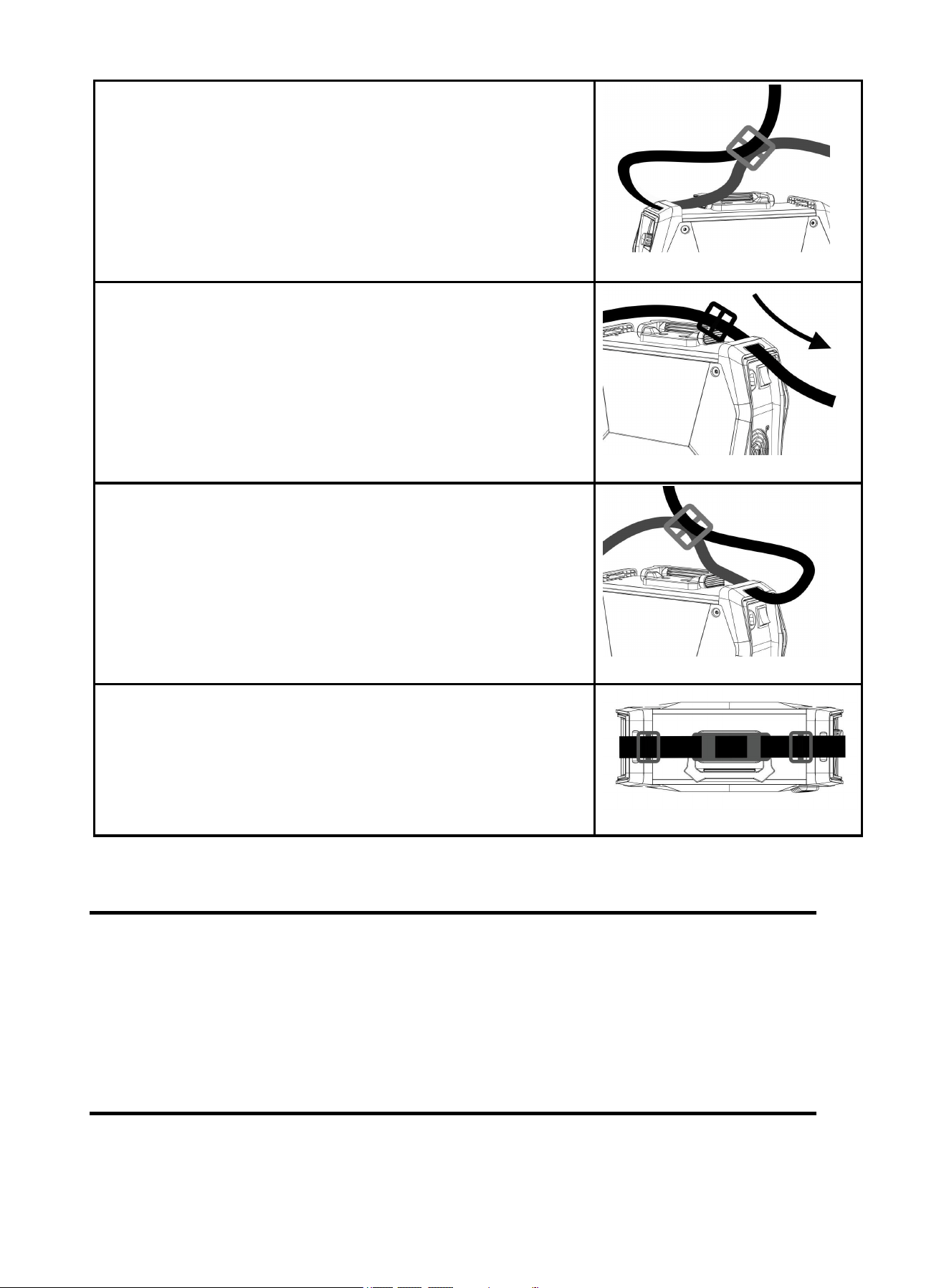
7. Strap Installation
Describe
Part
Select
Press the Weld Mode button , for Lift-TIG welding mode
changeover.
Step 1: Thread the strap through the strap hole in front of the
welder.
Figure 15
20
8. BASIC KNOWLEDGE OF WELDING
Manual metal arc welding, MMA for short, is an arc welding mode by manually operating electrode.
Equipment for MMA is simple, convenient and flexible to operate, and with high adaptability. MMA is
applied to various metal materials with thickness more than 0.08inch and various structures, in particular
to weldment with complex structure and shape, short weld joint or bending shape, as well as weld joints
in various spatial locations.
8.1 Welding Process Of MMA
Connect the two output terminals of the welder to the weldment and electrode holder respectively,
and then clamp the electrode by the electrode holder. When welding, arc is ignited between the
electrode and the weldment, and the end of the electrode and part of the weldment are fused to form a
Step 2: Thread the strap through the nylon buckle as shown in the
diagram.
Figure 16
Step 3: Thread the strap through the strap hole in back of the
welder.
Figure 17
Step 4: Thread the strap through the nylon buckle as shown in the
diagram.
Figure 18
Step 5: The strap installation is complete.
Figure 19
21
weld crater under the high-temperature arc. The weld crater is quickly cooled and condensed to form
weld joint which can firmly connect two separate pieces of weldement as a whole. The coating of the
electrode is fused to produce slag to cover the weld crater. The cooled slag can form slag crust to protect
the weld joint. The slag crust is removed at last, and the joint welding is finished.
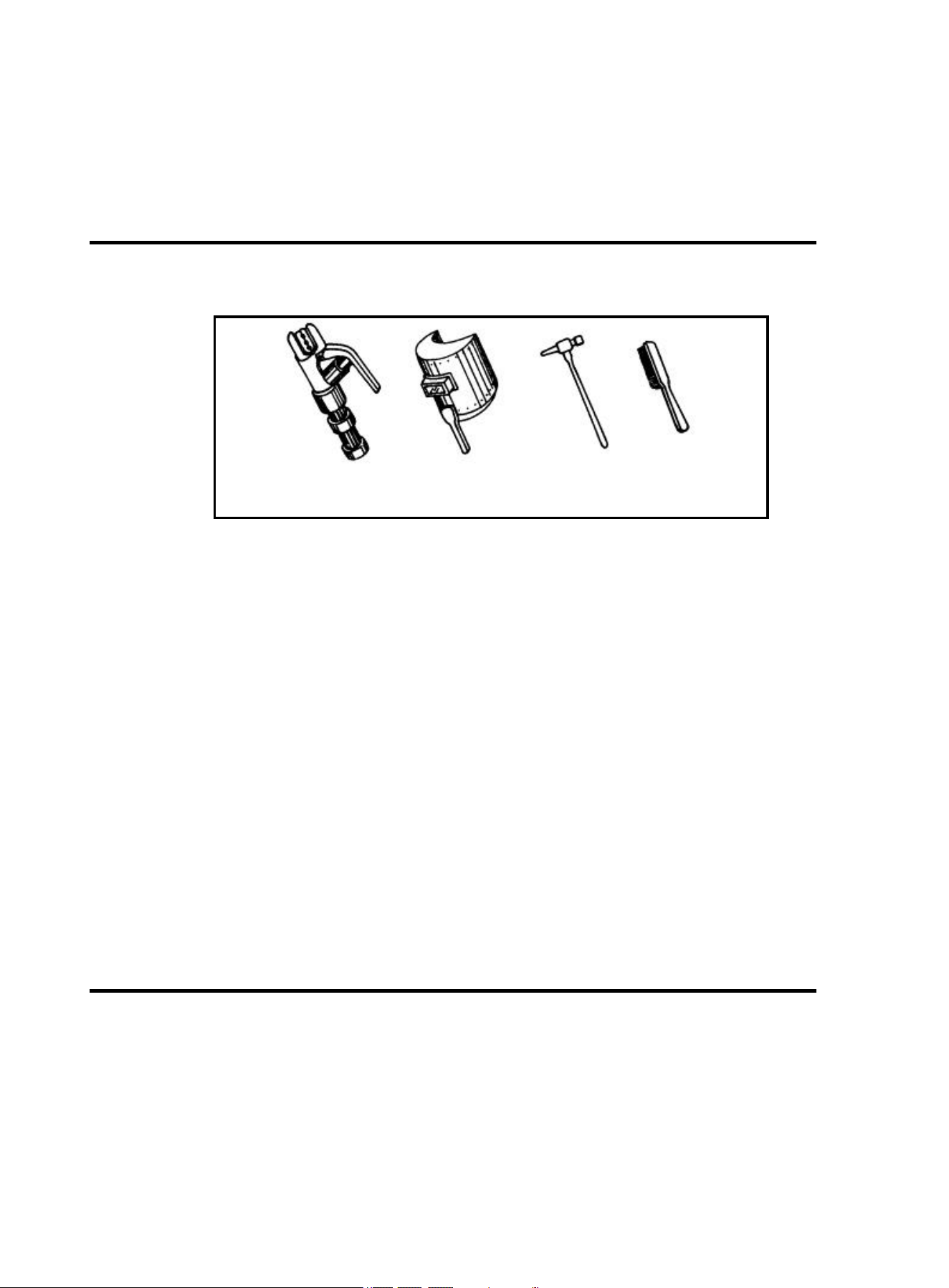
8.2 Tools For MMA
Common tools for MMA include electrode holder, welding mask, slag hammer, wire brush (see
Figure 20), welding cable and labor protection supplies.
a) electrode holder b) welding mask c) slag hammer d) wire brush
Figure 20 Tools for MMA
Electrode holder: a tool for clamping electrode and conducting current, mainly including 300A type
and 500A type.
Welding mask: a shielding tool for protecting eyes and face from injuring due to arc and spatter,
including handholding type and helmet type. Colored chemical glass is installed on the viewing
window of the mask to filter ultraviolet ray and infrared ray. Arc burning condition and weld crater
condition can be observed from the viewing window during arc burning. Thus, welding can be
carried out by operators conveniently.
Slag hammer (peen hammer): for the use of removing slag crust on the surface of weld joint.
Wire brush: for the use of removing dirt and rust at the joints of the weldment before welding, as well
as cleaning the surface of weld joint and the spatter after welding.
Welding cable: generally cables formed from many fine copper wires. Both YHH type arc welding
rubber sleeve cable and THHR type arc welding rubber sleeve extra-flexible cable can be used.
Electrode holder and welding machine are connected via a cable, and this cable is named as
welding cable (live wire). Welding machine and workpiece are connected via another cable (earth
wire). The electrode holder is covered with insulating material performing insulation and heat
insulating.
8.3 Basic Operation Of MMA
Welding joint cleaning
Rust and greasy dirt at the joint should be removed completely before welding in order to implement arc
igniting and arc stabilizing conveniently as well as ensure the quality of weld joint. Wire brush can be
used for condition with low requirement on dust removal; grinding wheel can be used for condition with
high requirement on dust removal.
Posture in operating
Take flat welding of butt joint and T-shaped joint from left to right as an example. (See Figure 21) The
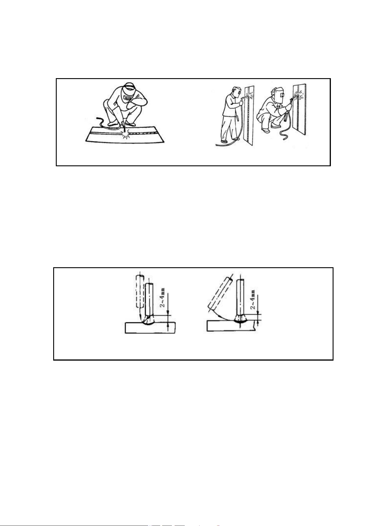
22
operator should stand at the right side of the working direction of weld joint with mask in the left hand and
electrode holder in the right hand. The left elbow of the operator should be put on his left knee to prevent
his upper body from following downwards, and his arm should be separated from the costal part so as to
stretch out freely.
`
a) flat welding
b) vertical welding
Figure 21 Posture in welding
Arc Igniting
Arc igniting is the process for producing stable arc between electrode and weldment in order to heat
them to implement welding. Common arc ignition mode includes scraping mode and striking mode. (See
Figure 22) During welding, touch the surface of the weldment with the end of the electrode by scraping
or light striking to form short circuit, and then quickly lift the electrode 0.08-0.16inch away to ignite arc. If
arc ignition fails, it is probably because there is coating at the end of the electrode, which affects the
electric conduction. In this case, the operator can strongly knock the electrode to remove the insulation
material until the metal surface of the core wire can be seen.
a)striking mode b) scraping mode
Figure 22 Arc ignition modes
Tack weld
For fixing the relative positions of the two pieces of weldment and welding conveniently, 1.2-1.6inch
short weld joints are welded every certain distance in order to fix the relative positions of the weldment
during welding assembly. This process is named as tack weld.
Electrode manipulation
The electrode manipulation actually is a resultant movement in which the electrode simultaneously
moves in three basic directions: the electrode gradually moves along the welding direction; the electrode
gradually moves toward the weld crater; and the electrode transversely swings. (See Figure 23)
Electrode should be correctly manipulated in three movement directions after arc is ignited. In butt
welding and flat welding, the most important is to control the following three aspects: welding angle, arc
length and welding speed.
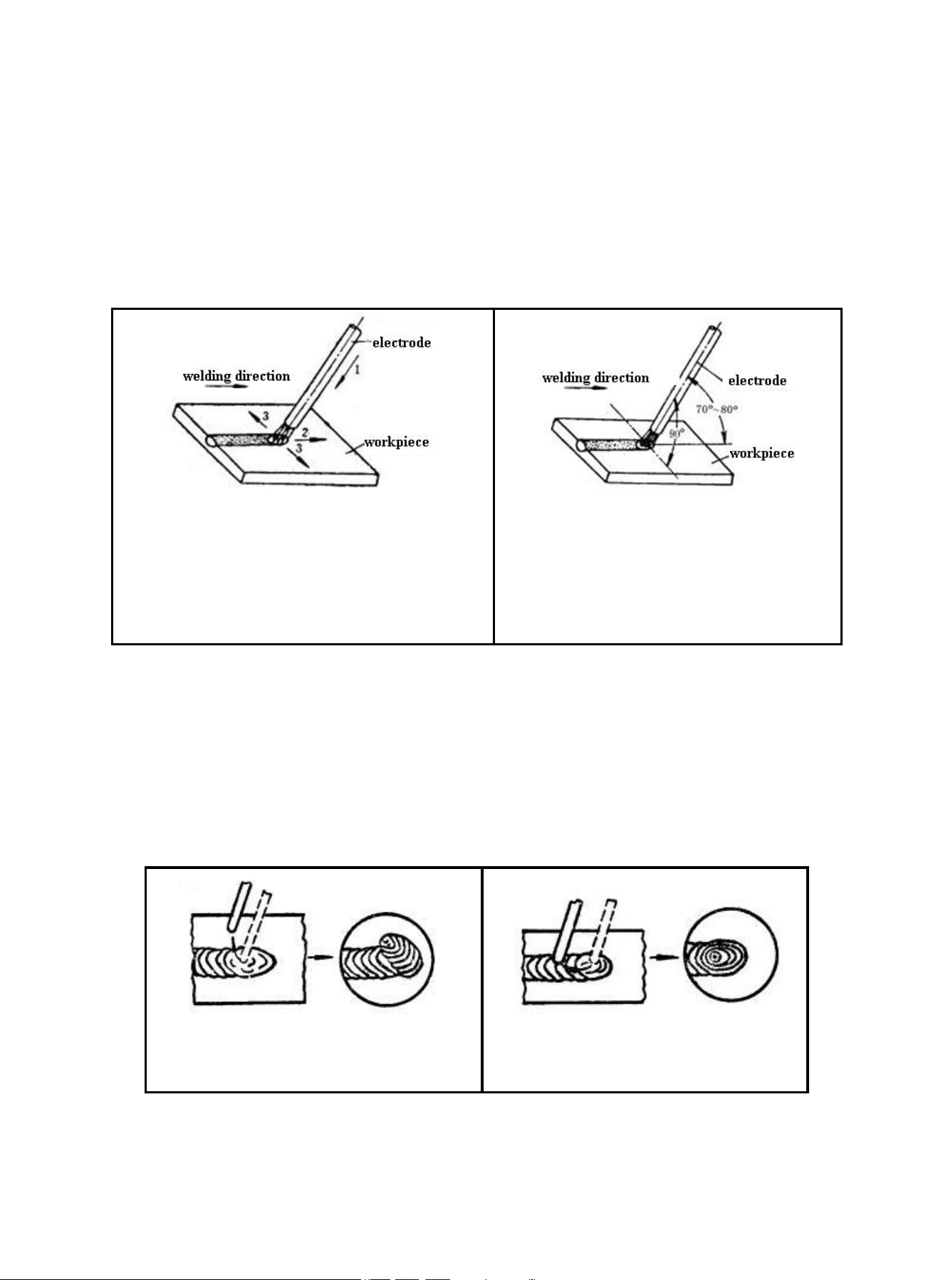
23
Welding angle: the electrode should be inclined in 70~80º forwards. (See Figure 24)
Arc length: the proper arc length is equal to the diameter of electrode in general.
Welding speed: proper welding speed should make the crater width of the weld bead about twice the
diameter of the electrode, and the surface of the weld bead should be flat with fine ripples. If the
welding speed is too high, and the weld bead is narrow and high, the ripples are rough, and the
fusion is not well implemented. If the welding speed is too low, the crater width is excessive, and the
workpiece is easy to be burned through. Besides, current should be proper, electrode should be
aligned, arc should be low, and welding speed should not be too high and should be kept uniform
during the whole welding process.
1-downwards feed
2-move toward welding direction
3-transversely swing
Figure 23 Three basic movement directions of
electrode
Figure 24 Angles of electrode in flat
welding
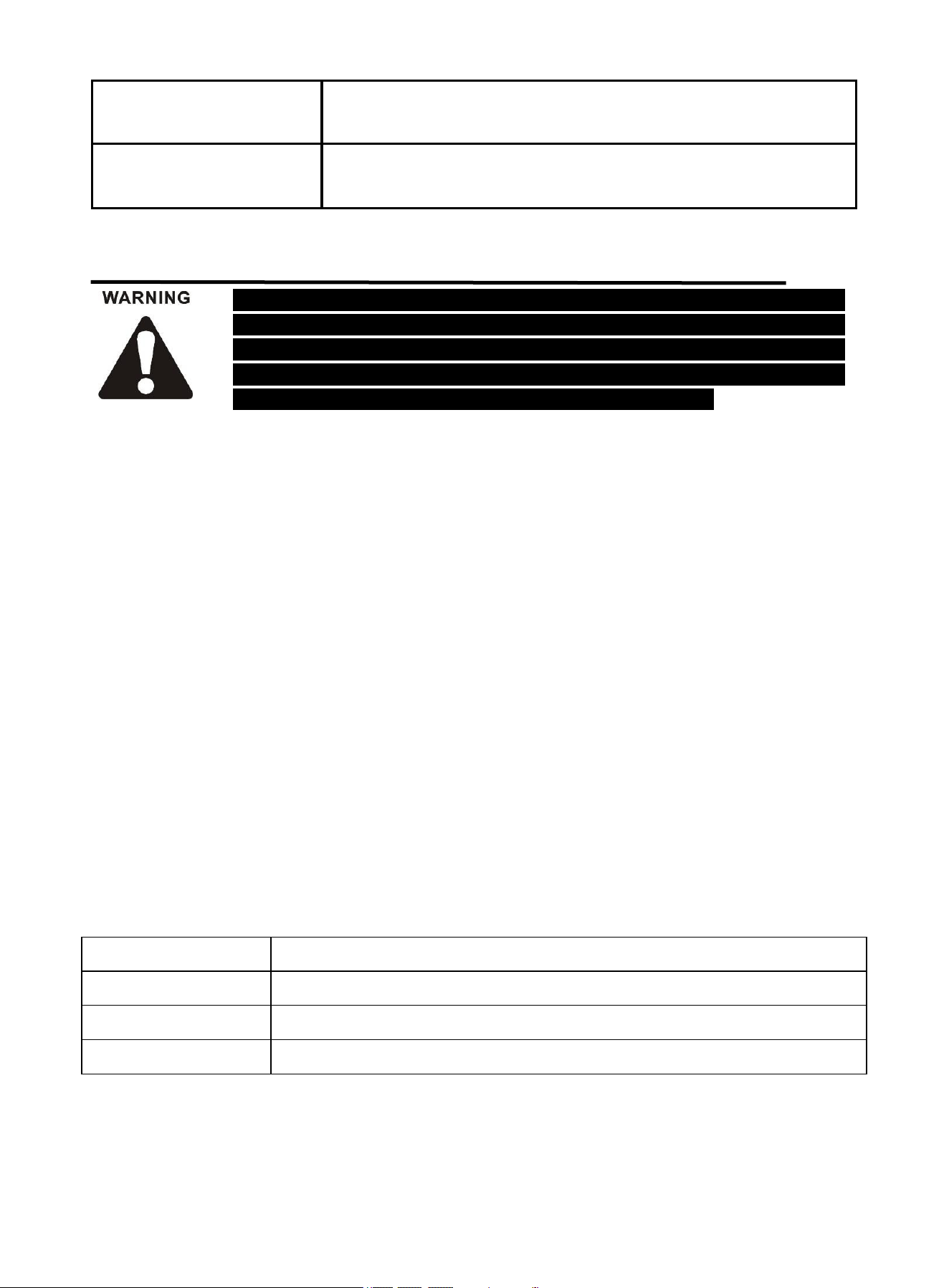
Arc extinguishing
Arc extinguishing is unavoidable during welding. Poor arc extinguishing may bring shallow weld crater
and poor density and strength of weld metal by which cracks, air holes, slag inclusion and shortage the
like are easy to be produced. Gradually pull the end of the electrode to the groove and raise the arc
when extinguishing arc, in order to narrow the weld crater and reduce the metal and heat. Thus, defects
such as cracks and air holes can be avoided. Pile up the weld metal of the crater to make the weld crater
sufficiently transferred when extinguishing arc. Then, remove the excessive part after welding. The
operation modes of arc extinguishing are shown in the figure below.
a) arc extinguishing at the outside of weld
bead
b) arc extinguishing on the weld bead
Figure 25 Arc extinguishing modes
Weldment cleaning
Clean welding slag and spatter with wire brush, etc after welding.
24
The following operation requires sufficient professional knowledge on
electric aspect and comprehensive safety knowledge. Operators should be
holders of valid qualification certificates which can prove their skills and
knowledge. Make sure the input cable of the machine is disconnected from
the electricity utility before uncovering the welding machine.
9. TROUBLESHOOTING
Common Malfunction Analysis and Solution:
NOTE: If the above solutions do not solve the problem, please contact ARCCAPTAIN Customer
Service.
Malfunction Phenomena
Causes and Solutions
Turn on the machine, the
power indicator is off, the fan
doesn't work, and no
welding output.
Check if the power switch is closed.
Make sure there is power for input cable.
Turn on the machine, the fan
works, but the output current
is unstable and can't be
controlled by encoder when
welding.
The current encoder fails. Replace it.
Check if any loose contact exists inside the machine, especially
connector, etc. If any, check.
Turn on the machine, the
power indicator is on, the fan
works, but no welding
output.
Check if any poor contact exists inside the machine.
Open circuit or poor contact occurs at the joint of output terminal.
The electrode holder
becomes very hot.
The rated current of the electrode holder is lower than its actual
working current. Replace it with a bigger rated current.
Excessive spatter in MMA
welding.
The output polarity connection is incorrect. Exchange the polarity.
Display indicates E-60
The machine is over-heating protection statues due to long time
operation.Waiting for 4-7 minutes and the machine will go back to
normal operation automatically
The thermistor is not well connected to control board.
The thermistor is damaged. Please replace it.
Display indicates E-10
Restart machine.
If it is not solved, the circuit fails. Please contact your distributor.
25
The following operation requires sufficient professional knowledge on
electric aspect and comprehensive safety knowledge. Operators should be
holders of valid qualification certificates which can prove their skills and
knowledge. Make sure the input cable of the machine is disconnected from
the electricity utility before uncovering the welding machine.
Display indicates E-34
Restart machine.
If it is not solved, the circuit fails. Please contact your distributor.
Non-arc
If it doesn't arc, make sure the ground clamp isn't clamped in an
insulated or rusted area
10. MAINTENANCE
Check periodically whether inner circuit connection is in good condition, connector is fastened (esp.
plugs or components). Tighten the loose connection. If there is oxidization, remove it with
sandpaper and then reconnect.
Keep hands, hair and tools away from the charged parts such as the fan to avoid personal injury or
machine damage when the machine is energized.
Clean the dust periodically with dry and clean compressed air. If welding environment with heavy
smoke and pollution, the machine should be cleaned daily. The pressure of compressed air should
be at a proper level in order to avoid the small parts inside the machine being damaged.
Avoid water and vapor infiltrating the machine. If there is, dry it and use tramegger to check the
insulation of the equipment (including that between the connections and that between the
connection and the enclosure). Only when there are no abnormal phenomena anymore, can the
machine be used.
Check periodically whether the insulation cover of all cables is in good condition. If there is any
dilapidation, rewrap it or replace it.
Put the machine into the original packing in dry location if it is not to be used for a long time.
Save for future reference:
Product:
Date Purchased:
Serial Number:
Product Feedback: