Lixel Holo 1
User Manual
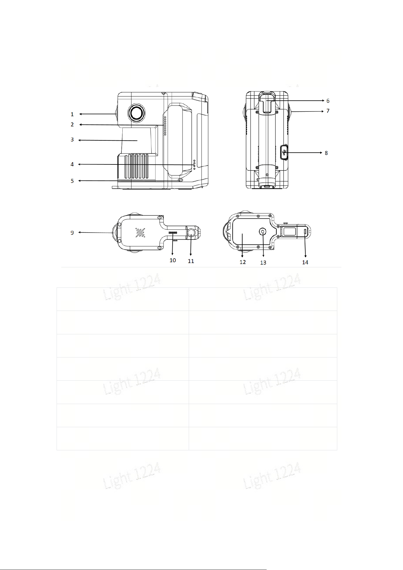
一:Product Overview
1:Front camera
2:Air outlet
3:LiDAR
4:Battery indicator light
5:Battery eject button
6:Cold shoe mount
7:Fisheye camera
8:USB port (cannot charge the battery)
9:Control point base
10:Sound outlet
11:Power button
12:Non-slip heat insulation pad
13:1/4-inch port
14:Battery base bayonet
1. When the device is powered on, it enters the normal power consumption mode.
If no scanning operation is initiated within 5 minutes, the device switches to low
power consumption mode, where its power consumption is approximately one-third
of that in normal mode. In low power mode, the LiDAR does not operate, but data
can still be copied. After data collection is completed, the device will also enter low
power mode if it remains idle for 5 minutes after scanning is stopped.
2. The device will emit an audible alert when powered on, powered off, when the
battery level is below 20%, and when below 10%. During recording, if the battery
level drops below 10%, the device will forcibly stop recording and save the data.
When the battery level is below 5%, the device will automatically power off to protect
itself.
3. If the battery level is below 10%, the device will not power on when the battery is
installed.
4. If the battery level displayed on the APP is abnormal, it may be that the battery is
not properly inserted. Please press the buckles on both sides of the battery into place
and check whether the battery level is normal again.
二:Basic Functions of the Equipment
2.1、Battery Installation and Charging
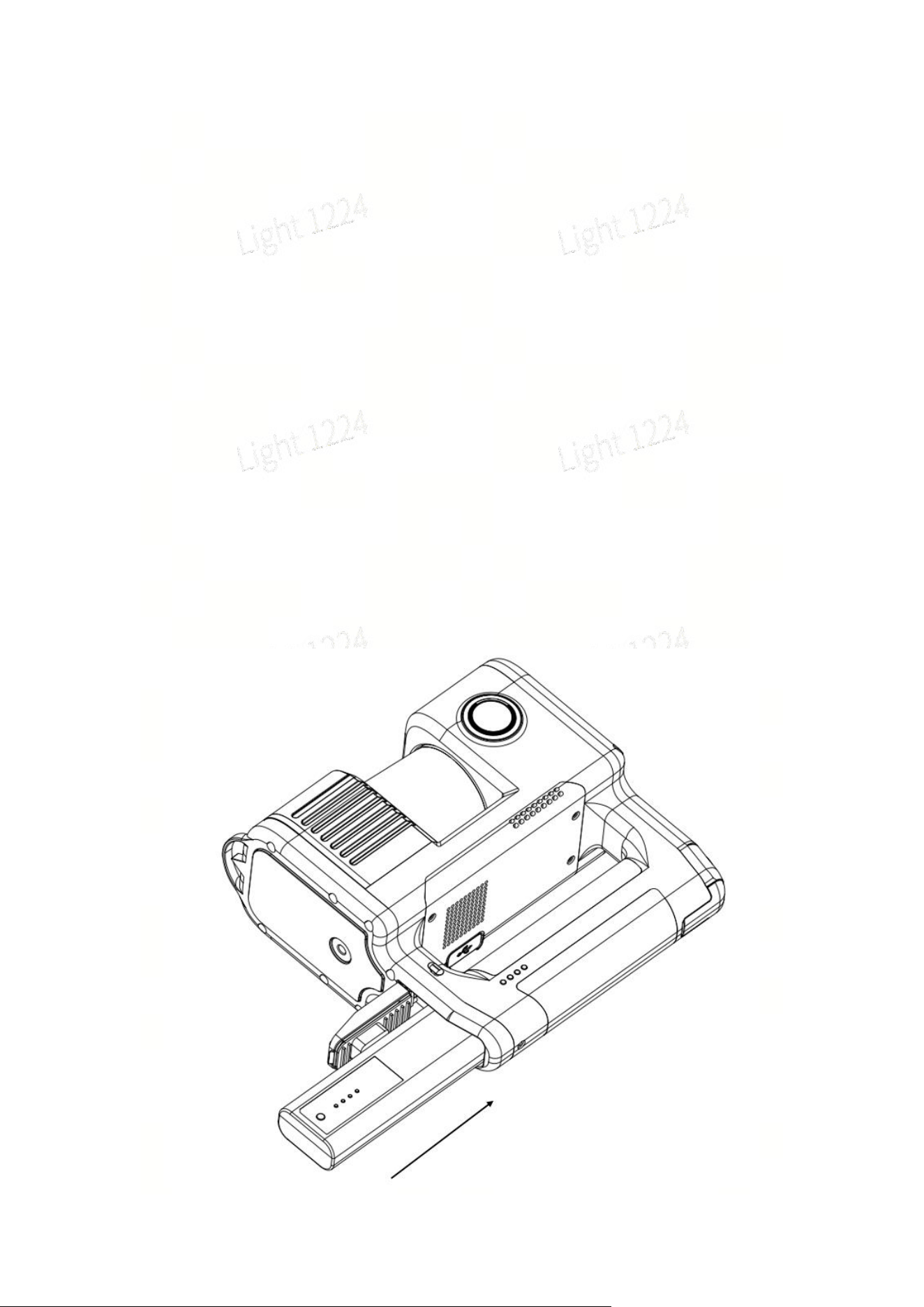
1、Battery Installation
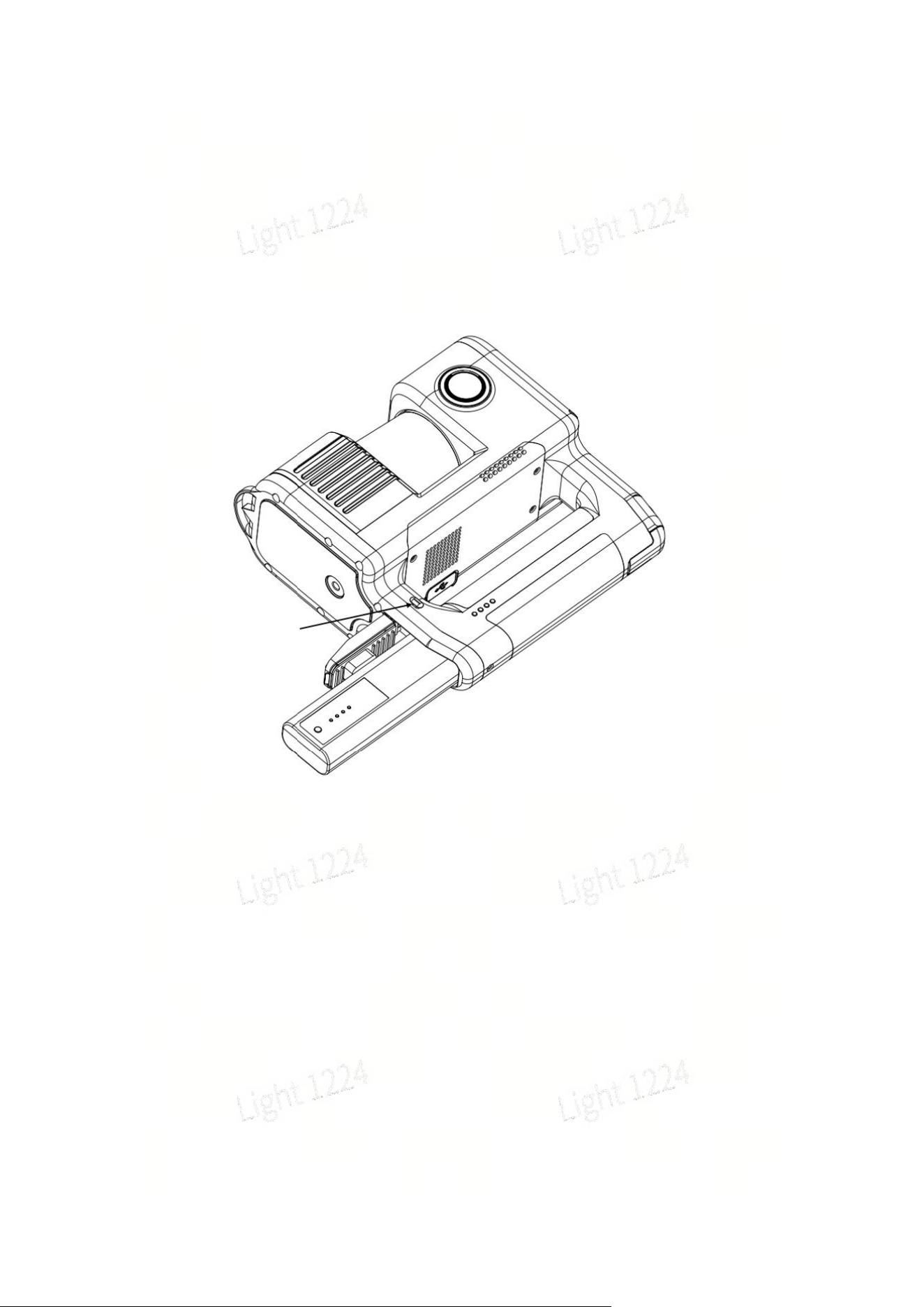
1、Follow the instructions in the image above, insert the battery slowly with one side
facing upward.
2、Push the battery into the bottom of the device along the guide slots until it is fully
inserted.
3、To remove the battery, press the button firmly in the direction indicated by the
arrow in the figure below. The battery will pop out; catch it by hand to prevent it from
falling.
2、Battery Charging and Indicator Lights
Use the standard charger and charging cable to connect to the Type-C port on the
battery manager. Insert the battery into the battery manager to start charging. The
charging time from 0 to 100% battery level is approximately 90 minutes. The
recommended ambient temperature for charging is 5℃ to 30℃.3、Description of
the battery indicator light during charging:
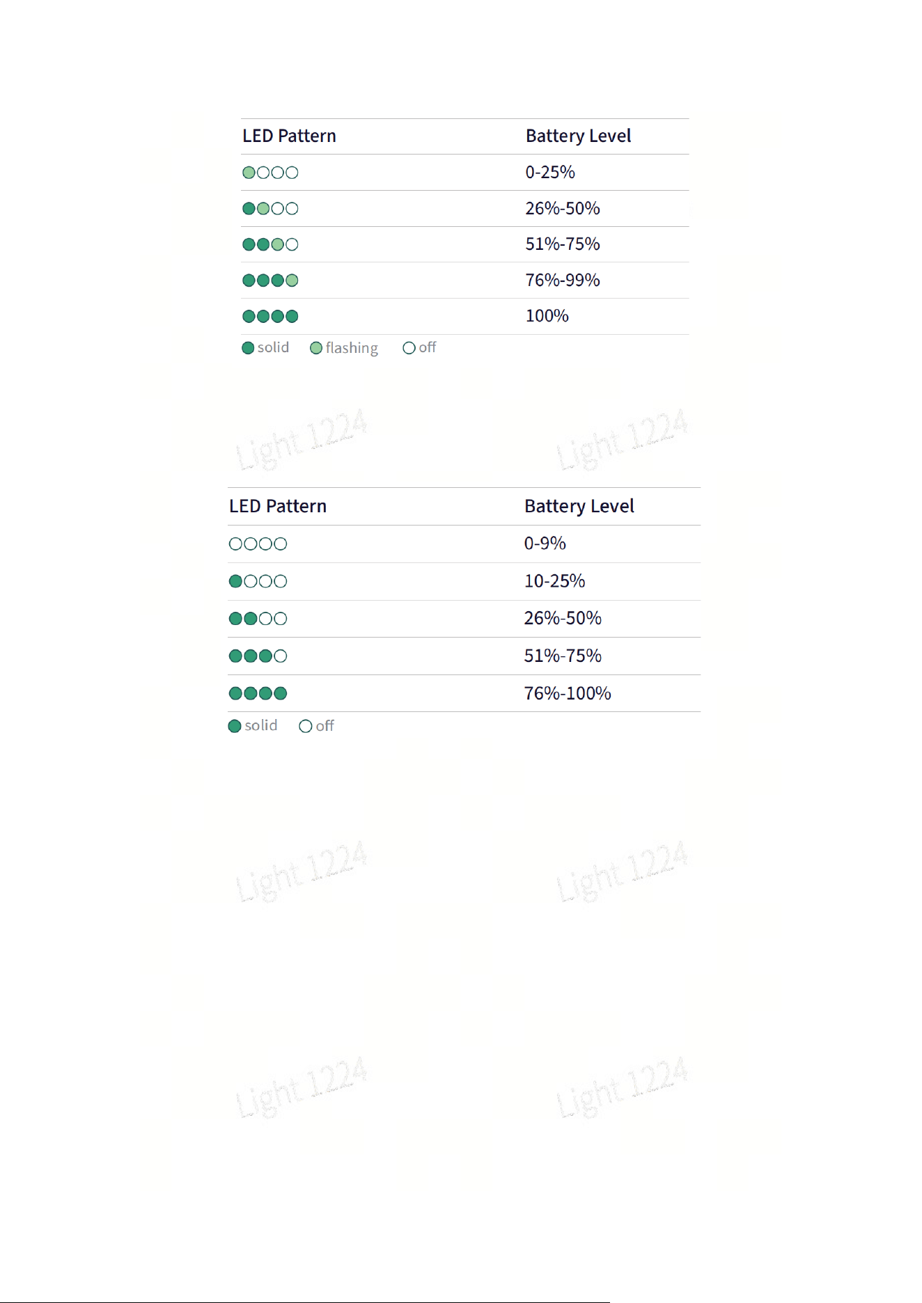
4、Indicator light description of the battery in non-charging status:
5、Battery Maintenance Instructions
1. After daily use of the device, the battery should be fully charged in a timely
manner.
2. For fully charged batteries that are not used for a long time, recharge them once
every 3 months.
3. For batteries with extremely low power or completely depleted power, they must
be charged within 3 days.
Damage to the battery caused by failure to follow the above requirements is
irreparable and not covered by the warranty.
Please perform timely maintenance to ensure the battery remains in good condition!
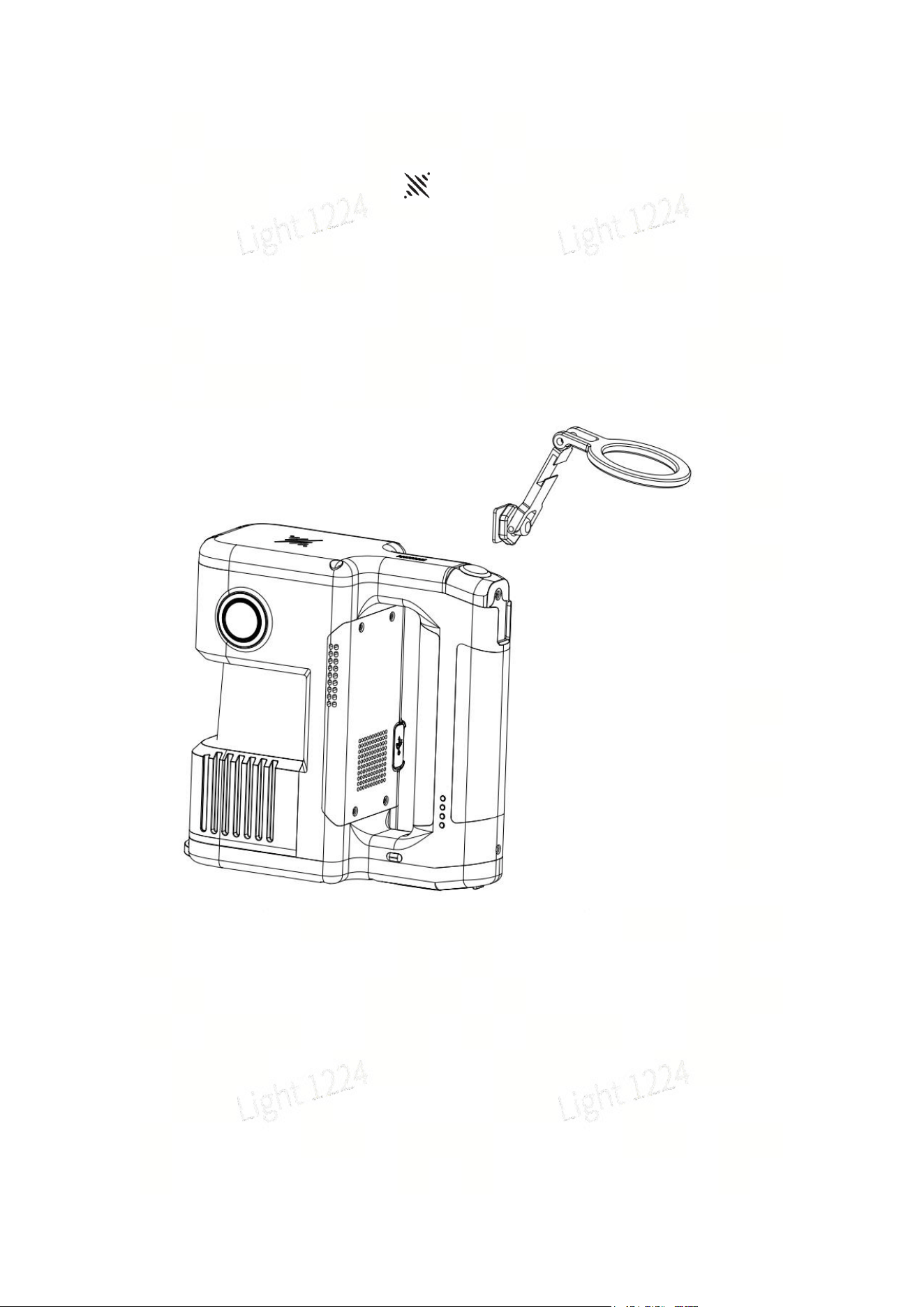
2.2、PDA Installation
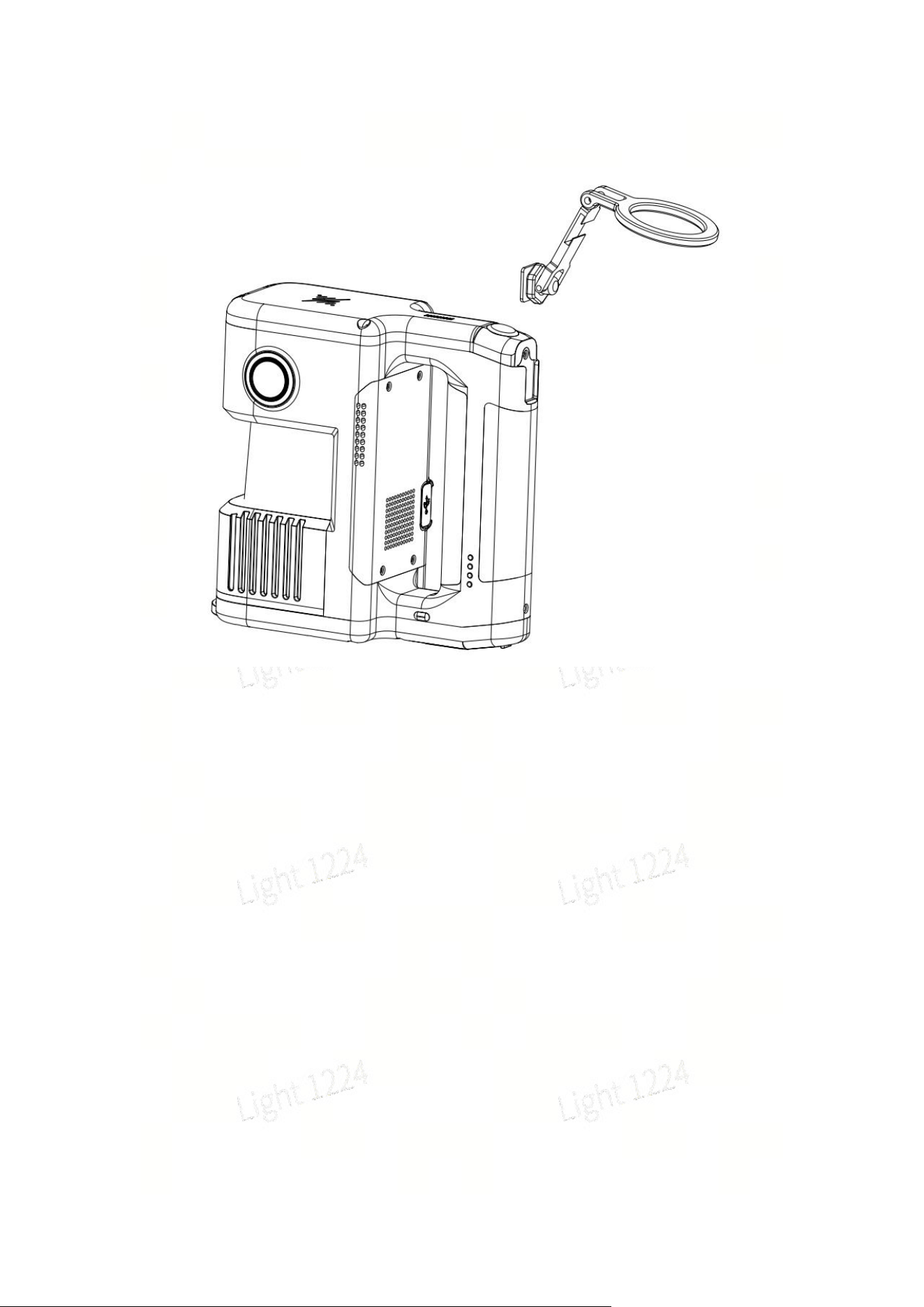
As shown in the figure below, insert the phone holder downward into the cold shoe
slot on the back cover of the device in the direction indicated by the arrow.
Attach the phone holder to the cold shoe mount of the device. The back of the PDA is
equipped with a magnetic ring, which can mate with the magnetic ring on the phone
holder to secure the PDA in place.
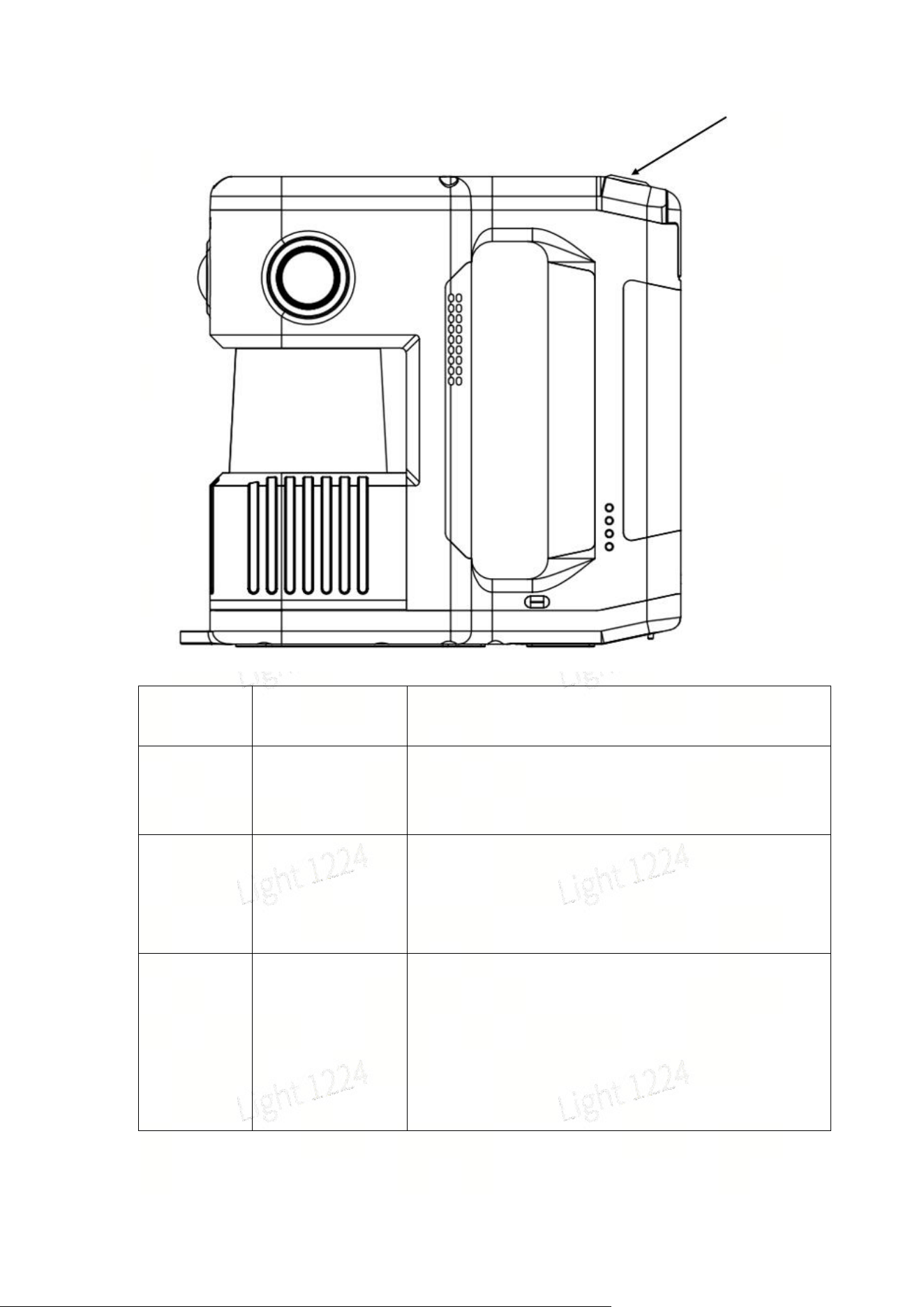
2.3:Description of Buttons and Indicator Lights
1、Device Buttons
As indicated by the arrow in the figure below, this is the only button on the device,
which controls functions such as power on, power off, scanning, and USB disk mode.
Functions
Button
Operations
Device Status Description
Power On
Long press the
battery button for
2 seconds
Long press the battery button for 2 seconds. When
the device indicator changes from slow flashing blue
to steady green, the device enters standby mode.
Power Off
Long press the
battery button for
2 seconds in
standby mode
When the device is in standby mode, long press the
battery button for 2 seconds. The indicator turns off,
indicating that the shutdown is complete.
Start Scan
Double click the
device button
When the device is in standby mode, double-click the
device button. The device indicator changes from
steady green to fast flashing green for about 20
seconds, then switches to slow flashing green,
indicating that scanning has started successfully and
the device has entered scan mode.

Stop Scan
Double click the
device button
When the device is in scan mode, double-click the
device button. The indicator changes from slow
flashing green to steady green, indicating that
scanning has stopped successfully and the device
returns to standby mode.
Switch to
USB Disk
Mode
Single click the
device button +
device indicator
lights up white +
single click the
device button
When the device is in standby mode, single-click the
device button, and the indicator will turn white for
approximately 3 seconds. Single-click the button
again while the white light is on to switch to USB disk
mode. If no further operation is performed within 3
seconds, the device will remain in standby mode.
When the device is in USB disk mode, single-click the
device button, and the indicator will turn white for
approximately 3 seconds. Single-click the button
again while the white light is on to switch to standby
mode. If no further operation is performed within 3
seconds, the device will remain in USB disk mode.
Notes
1. Before starting scanning, place the device on a flat and stable surface. After
starting scanning, do not move the device for scanning until the green light flashes
slowly.
2. The device startup time is approximately 25 seconds, and the scanning startup
time is about 20 seconds.
3. During the scanning stop process, if the indicator light flashes green rapidly, it
means the device is saving the scanned files. Powering off at this time may result in
file loss or incomplete saving.
4. After scanning stops, the green fast flashing may last for a relatively long time,
depending on the size of the scanning area.
2、Device Indicator Description
LED Pattern
Status
Off
Device not started
Solid green
Standby mode
Fast green flash
Starting/stopping scan

Slow green flash
Scanning mode
Slow blue flash
Starting up
Solid blue
USB mode
Solid yellow
Device not activated
Solid white
Mode switching
Solid red
Critical error
Red-green alternating
Firmware update(The battery level needs to
be above 50%)
2.4:Data Copying
When the device is in standby mode (green indicator steady on), connect it to a
computer using the included USB 3.0 cable. After about 5 seconds, the device will
automatically enter USB disk mode (currently only desktop computers and laptops
support automatic entry into USB disk mode; mobile phones and tablets require
switching via the APP or device button). Once the computer recognizes the device,
data copying can be performed. After copying is complete, unplug the USB cable,
and the device will automatically exit USB disk mode and return to standby status.
Notes
1. USB disk mode will be disabled automatically after the device restarts.
2. After enabling USB disk mode, if the device is not powered off or disconnected,
you must manually disable USB disk mode to continue scanning operations.
3. Please use the included USB 3.0 cable. Using other cables may result in slower
copying speeds, or only work when inserted in one direction and fail when reversed.
2.5:Firmware Upgrade
The device firmware can be upgraded according to the prompts in the APP. There
are two types of firmware upgrades: full package upgrade and small package
upgrade. A small package upgrade can be performed directly on the device via the
APP. If the APP prompts for a full package upgrade, follow the steps below:
1. Download the required full package firmware from the official website (usually
larger than 1GB).
2. Switch the device to USB disk mode, and copy the firmware to the root directory

of the device storage.
3. Power off the device and restart it. The device will automatically enter firmware
upgrade mode after rebooting.
三:Maintenance and Care
4.1、Storage
4.2、Safety and Precautions
1. Prevent Drops and Impacts: This device is precision equipment. Dropping or
subjecting it to external impacts may cause damage, resulting in abnormal operation
or accuracy deviation.
2. Operating Environment and Cleaning: Do not use the device in dusty
environments or rainy conditions. For cleaning, it is recommended to use a soft dry
cloth or the included cleaning cloth to keep the radar window and lens surface clean.
Do not touch the lens directly with your hands.
3. Initialization: Support the device with a tripod and place it on a flat, stable surface
to complete initialization. Avoid performing initialization on uneven ground, as this
may cause initialization failure or increased mapping thickness.
4. Temperature Safety: The device generates heat during operation. Avoid direct
contact with the main body to prevent burns.
5. Heat Dissipation Protection: Do not cover or block the heat dissipation area
during use. Obstructed heat dissipation will reduce cooling efficiency and may cause
the device to stop operating automatically in severe cases.
Appendix:
Model
Lixel Holo 1
Remarks
Overall
Power
≤22W

Performance
Weight
About 1.6Kg
Dimensions
192mm*87mm*181mm
Data Interface
USB 3.0
Internal Storage
EMMC 512G
RTK Module
Supported
WiFi
2.400 GHz ~ 2.4835 GHz
5.15 GHz ~ 5.850 GHz
Bluetooth
BT5.2
Operating
Ambient
Temperature
-20℃~50℃(No solar
radiation)
Power Supply
Method
Plug-in / Removable
Battery
Working Duration
120min
Battery Capacity
48.24Wh
Charging Time
(Room
temperature: 25
degrees
Celsius)
0%~100% about 100min
Charging
Manager
Supported
Recommended
charging ambient
temperature
5℃~30℃
Number of
batteries
supported by the
charging
3(Not simultaneously)

manager
Number of
Cameras
3(Fisheye*2,Front
View*1)
Output Format
Point Cloud Format .las
Image Format .Jpg
Real-time
Accuracy
Absolute
Accuracy
(Elevation)(RMS
E)
3cm
Control point /
RTK
disconnection
< 100m
Absolute
Accuracy
(Horizontal)(RMS
E)
3cm
Control point /
RTK signal
loss < 100
meters
Relative
Accuracy(RMSE)
1cm
The distance
between two
points is less
than 10m.
Repeatability
Accuracy(RMSE)
2cm
For the same
scene and
same route:
two scans with
RTK
Point Cloud
Thickness
1cm
Point cloud
plane
thickness
within 10m of
the walking
path
Levelness (RTK /
Control Point
Fusion)
0.015°
RTK:
Continuous
connection
within
100m;Control
points: Interval
between
control points

< 100m
Dynamic Object
Removal
Supported
Loop Closure
Detection
Supported
Post-
processing
Accuracy
Absolute
Accuracy
(Elevation)(RMS
E)
3cm
Control point /
RTK
disconnection
< 100m
Absolute
Accuracy
(Horizontal)(RMS
E)
3cm
Control point /
RTK
disconnection
< 100 m
Relative
Accuracy(RMSE)
4mm
Distance
between two
points < 10 m
Repeatability
Accuracy(RMSE)
1cm
For the same
scene and
same route:
two scans with
RTK enabled
Point Cloud
Thickness
3mm
Point cloud
plane
thickness
within 10m of
the walking
path
Levelness (RTK /
Control Point
Fusion)
0.015°
Point Cloud
Enhancement
Supported
Maximum
enhanced
point cloud
density: 1 mm

Dynamic Object
Removal
Supported
Loop Closure
Detection
Supported
Laser Module
Laser Class
Class 1 / 905nm
Scanning
Distance
0.1m~70m@10%,
95m@90%
Field of View
Azimuth360°
(Occlusion90°) *
Pitch60°
Point Cloud
Frequency
200,000 points per second
RTK Module
Supported
Frequency Bands
Support
Accuracy
Plane:0.8 cm + 1 ppm
Elevation:1.5 cm + 1
ppm
Vision Module
Fisheye Camera
FOV
200°*200°
Front Camera
FOV
100°*85°
All Camera
Resolutions
4000*3000
CMOS Size
1/2’’
Camera Shutter
Rolling shutter
Accessories
Packing box
Standard configuration
PDA
Standard equipment


This device complies with part 15 of the FCC Rules. Operation is subject to the
following two conditions: (1) This device may not cause harmful interference, and (2)
this device must accept any interference received, including interference that may cause
undesired operation.
Any Changes or modifications not expressly approved by the party responsible for
compliance could void the user's authority to operate the equipment.
Note: This equipment has been tested and found to comply with the limits for a Class B
digital device, pursuant to part 15 of the FCC Rules. These limits are designed to
provide reasonable protection against harmful interference in a residential installation.
This equipment generates uses and can radiate radio frequency energy and, if not
installed and used in accordance with the instructions, may cause harmful interference
to radio communications. However, there is no guarantee that interference will not
occur in a particular installation. If this equipment does cause harmful interference to
radio or television reception, which can be determined by turning the equipment off and
on, the user is encouraged to try to correct the interference by one or more of the
following measures:
-Reorient or relocate the receiving antenna.
-Increase the separation between the equipment and receiver.
-Connect the equipment into an outlet on a circuit different from that to which the
receiver is connected.
-Consult the dealer or an experienced radio/TV technician for help.
-This equipment complies with FCC radiation exposure limits set forth for an
uncontrolled environment. This equipment should be installed and operated with
minimum distance 20cm between the radiator & your body.