BCD260DN
Owner’s Manual
© 2023 Uniden America Corporation Printed in Vietnam
Flower Mound, Texas USA U01UB389ZZZ(0)

PRECAUTIONS
Before you use this scanner, please read and observe the following.
EARPHONE WARNING!
Be sure to use only a monaural earphone with this scanner. You can also use
an optional stereo headset. Use of an incorrect earphone or mono headset
might be potentially hazardous to your hearing. The output of the phone jack is
monaural, but you will hear it in both headphones of a stereo headset.
Set the volume to a comfortable audio level coming from the speaker
before plugging in the monaural earphone or headset. Otherwise, you might
experience some discomfort or possible hearing damage if the volume
suddenly becomes too loud because of the volume control or squelch control
setting. This might be particularly true of the type of earphone that is placed in
the ear canal.
WATERPROOF WARNING!
Uniden does not represent this unit to be waterproof. To reduce the risk of re
or electrical shock, do not expose this unit to rain or moisture.
© 2023 Uniden America Corporation, Flower Mound, Texas.
Questions? Problems? Get help on the web at www.uniden.com.

CONTENTS
IMPORTANT INFORMATION ..................................................................... 5
THE FCC WANTS YOU TO KNOW .....................................................................................5
MODIFICATION NOTICE ..................................................................................................... 5
PART 15 INFORMATION .....................................................................................................5
SCANNING LEGALLY ..........................................................................................................5
ISED COMPLIANCE .............................................................................................................6
INFORMATION IMPORTANTE ................................................................... 7
LA FCC VEUT QUE VOUS SACHIEZ ..................................................................................7
AVIS DE MODIFICATION .....................................................................................................7
INFORMATION RELATIVE À L’ARTICLE 15 ....................................................................... 7
UTILISER UN SCANNEUR DE MANIÈRE LÉGALE............................................................8
CONFORMITÉ ISED .............................................................................................................8
OBTENIR LE GUIDE D’UTILISATION BCD260DN EN FRANÇAIS .................................... 9
UNIDEN BCD260DN
DIGITAL SCANNER .................................................................................. 10
FEATURES ..........................................................................................................................10
INCLUDED WITH YOUR SCANNER .................................................................................. 12
SCANNING BASICS ................................................................................. 12
WHAT IS SCANNING? .......................................................................................................13
WHAT IS SCANNING? .......................................................................................................13
UNDERSTANDING BANKS ................................................................................................14
WHERE TO LEARN MORE ................................................................................................15
KEYPAD AND KNOB CONTROLS .......................................................... 15
BCD260DN FRONT PANEL ...............................................................................................15
BCD260DN REAR PANEL
............................................................................................................................................. 18
BCD260DN BASIC SETUP ...................................................................... 19
SETTING UP YOUR SCANNER .........................................................................................19
SETTING UP AN AUDIO OR COMPUTER RECORDING ..................................................20
VEHICLE INSTALLATION ..................................................................................................21
A LOOK AT THE DISPLAY ....................................................................... 28
MENUS ..................................................................................................... 31
USING MENUS ...................................................................................................................31
ENTERING/SELECTING DATA ..........................................................................................31
BCD260DN OPERATION SETUP ............................................................ 32
PROGRAM CHANNELS ..................................................................................................... 33
SEARCH MODE ..................................................................................................................38
PRIORITY SCAN .................................................................................................................49
WEATHER (WX) OPERATION ................................................................. 50
WEATHER SCAN ...............................................................................................................51
WEATHER ALERT .............................................................................................................51
PROGRAM SAME GROUPS .............................................................................................. 52
SET DELAY TIME ...............................................................................................................53
SET ATTENUATOR ............................................................................................................53
SET RECORD .....................................................................................................................53
WX ALERT (ALT) PRIORITY ..............................................................................................54

TONE-OUT FOR... .................................................................................... 54
USING TONE-OUT STANDBY/SEARCH ..........................................................................56
IN TONE-OUT STANDBY MODE........................................................................................57
BAND SCOPE MODE ............................................................................... 57
USING BAND SCOPE MODE.............................................................................................58
SETTINGS ................................................................................................. 62
SET BACKLIGHT................................................................................................................62
SET RX LED........................................................................................................................62
ADJUST KEY BEEP ...........................................................................................................62
SET UPSIDE-DOWN ...........................................................................................................63
ADJUST CONTRAST .........................................................................................................63
BAND DEFAULTS ...............................................................................................................63
FACTORY RESET ............................................................................................................... 63
FIRMWARE VERSION ........................................................................................................ 63
OTHER OPERATIONS ............................................................................. 64
VIEWING THE DIGITAL DECODER ERROR RATE ..........................................................64
UPDATE FIRMWARE USING PC .......................................................................................64
HOW DO I . . . ? ........................................................................................ 64
APPENDIX A ............................................................................................. 66
BAND DEFAULTS ...............................................................................................................66
WEATHER CHANNELS ......................................................................................................67
SAME EVENT CODES........................................................................................................67
CTCSS TONES ...................................................................................................................71
DCS CODES .......................................................................................................................71
APPENDIX B - MENU STRUCTURE ........................................................ 72
PROGRAM CHANNEL MENU ............................................................................................ 72
SEARCH OPTIONS MENU .................................................................................................74
SEARCH FOR... MENU ......................................................................................................74
PRIORITY SCAN MENU .....................................................................................................76
WX OPERATION MENU .....................................................................................................77
TONE-OUT FOR... MENU ................................................................................................... 78
SETTINGS MENU ...............................................................................................................79
TECHNICAL SPECIFICATIONS ............................................................... 81

5
IMPORTANT INFORMATION
THE FCC WANTS YOU TO KNOW
IMPORTANT! This scanning radio has been manufactured so that it will not
tune to the radio frequencies assigned by the FCC for cellular telephone
usage. The Electronic Communications Privacy Act of 1986, as amended,
makes it a federal crime to intentionally intercept cellular or cordless telephone
transmissions or to market this radio when altered to receive them. The
installation, possession, or use of this scanning radio in a motor vehicle may
be prohibited, regulated, or require a permit in certain states, cities, and/
or local jurisdictions. Your local law enforcement ofcials should be able to
provide you with information regarding the laws in your community.
MODIFICATION NOTICE
Changes or modications to this product not expressly approved by Uniden,
or operation of this product in any way other than as detailed by this Owner’s
Manual, could void your authority to operate this product.
PART 15 INFORMATION
This scanner has been tested and found to comply with the limits for a
scanning receiver, pursuant to Part 15 of the FCC Rules. These limits are
designed to provide reasonable protection against harmful interference in
a residential installation. This scanner generates, uses, and can radiate
radio frequency energy and, if not installed and used in accordance with the
instructions, may cause harmful interference to radio communications.
There is no guarantee that interference will not occur in a particular
installation. If this scanner does cause harmful interference to radio or
television reception, which can be determined by turning the scanner on and
off, you are encouraged to try to correct the interference by one or more of the
following measures:
• Reorient or relocate the receiving antenna.
• Increase the separation between the scanner and the receiver.
This device complies with Part 15 of the FCC Rules. Operation is subject
to the following two conditions: (1) this device may not cause harmful
interference, and (2) This device must accept any interference received,
including interference that may cause undesired operation.
SCANNING LEGALLY
Your scanner covers frequencies used by many different groups, including
police and re departments, ambulance services, government agencies,
private companies, amateur radio services, military operations, paging
services, and wireline (telephone and telegraph) service providers. It is legal to

6
listen to almost every transmission your scanner can receive. However, there
are some transmissions that you should never intentionally listen to.
These include:
• Telephone conversations (cellular, cordless, or other private means of
telephone signal transmission)
• Pager transmissions
• Any scrambled or encrypted transmissions
According to the Electronic Communications Privacy Act (ECPA), you are
subject to nes and possible imprisonment for intentionally listening to, using,
or divulging the contents of such a conversation unless you have the consent
of a party to the conversation (unless such activity is otherwise illegal). This
scanner has been designed to prevent the reception of cellular telephone
transmissions and the decoding of scrambled transmissions. This is done to
comply with the legal requirement that scanners be manufactured so they are
not easy to modify to pick up these transmissions. Do not open your scanners
case to make any modications that could allow it to pick up transmissions
that are illegal to monitor. Modifying or tampering with your scanners internal
components or using it in a way other than as described in this manual could
invalidate your warranty and void your FCC authorization to operate it. In
some areas, mobile and/or portable use of this scanner is unlawful or requires
a permit. Check the laws in your area. It is also illegal in many areas (and a
bad idea everywhere) to interfere with the duties of public safety ofcials by
traveling to the scene of an incident without authorization.
ISED COMPLIANCE
In Canada, obtaining a license is required before purchasing and operating
this scanner.
As per the Radio Standards Specication for Digital Scanner Receivers,
RSS-135, Issue 2, clause 2.1, “Licensing Requirements,” reproduced herein:
“The equipment covered by this standard is subject to licensing pursuant to
subsection 4(1) of the Radiocommunication Act.”
This device complies with Industry Canada RSS standard(s). Operation
is subject to the following two conditions: (1) this device may not cause
interference, and (2) this device must accept any interference, including
interference that may cause undesired operation of the device.

7
INFORMATION IMPORTANTE
LA FCC VEUT QUE VOUS SACHIEZ
IMPORTANT! Cette radio à balayage a été fabriquée de telle sorte qu’elle ne
se règle pas sur les fréquences radio attribuées par la FCC pour l’utilisation
des téléphones cellulaires. La loi sur la condentialité des communications
électroniques de 1986, telle que modiée, fait de l’interception intentionnelle
des transmissions téléphoniques cellulaires ou sans l ou de la
commercialisation de cette radio lorsqu’elle est modiée pour les recevoir
un crime fédéral. L’installation, la possession ou l’utilisation de cette radio
à balayage dans un véhicule à moteur peut être interdite, réglementée ou
nécessiter un permis dans certains États, villes et/ou juridictions locales. Les
responsables locaux de l’application de la loi devraient pouvoir vous fournir
des informations sur les lois en vigueur dans votre communauté.
AVIS DE MODIFICATION
Les changements ou les modications apportés à cet appareil qui n’ont pas
été expressément approuvés par Uniden, ou l’utilisation de cet appareil d’une
manière autre que celle décrite dans ce Guide de l’utilisateur, peuvent annuler
votre droit d’utiliser cet appareil.
INFORMATION RELATIVE À L’ARTICLE 15
Ce scanneur a été testé et déclaré conforme aux limites imposées à un
récepteur de balayage, conformément à la partie 15 des règles de la FCC.
Ces limites sont conçues pour fournir une protection raisonnable contre
les interférences nuisibles dans une installation résidentielle. Ce scanner
génère, utilise et peut émettre de l’énergie de fréquence radio et, s’il n’est
pas installé et utilisé conformément aux instructions, peut causer des
interférences nuisibles aux communications radio.Il n’y a aucune garantie
que des interférences ne se produiront pas dans une installation particulière.
Si ce scanner provoque des interférences nuisibles à la réception de la radio
ou de la télévision, ce qui peut être déterminé en allumant et en éteignant le
scanner, nous vous encourageons à essayer de corriger ces interférences par
l’une ou plusieurs des mesures suivantes:
• Réorientez ou déplacez l’antenne de réception.
• Éloignez l’appareil du composant qui reçoit les interférences.
Cet appareil est conforme à l’article 15 des règlements de la FCC. Son
fonctionnement est soumis aux deux conditions suivantes : (1) cet appareil
ne doit pas causer d’interférences nuisibles, et (2) cet appareil doit accepter
toute interférence reçue, y compris les interférences pouvant causer un
fonctionnement indésirable.

8
UTILISER UN SCANNEUR DE MANIÈRE LÉGALE
Votre scanneur couvre les fréquences utilisées par de nombreux groupes
différents, notamment les services de police et d’incendie, les services
d’ambulance, les agences gouvernementales, les entreprises privées,
les services de radio amateurs, les opérations militaires, les services
de téléavertisseurs et les fournisseurs de services laires (téléphone et
télégraphe). Il est légal d’écouter presque toutes les transmissions que votre
scanner peut recevoir. Cependant, il existe certaines transmissions que vous
ne devez jamais écouter intentionnellement. Il s’agit notamment de :
• Conversations téléphoniques (cellulaires, sans l ou autres moyens
privés de transmission de signaux téléphoniques)
• Transmissions de téléavertisseurs
• Toutes transmissions brouillées ou cryptées
Selon la loi sur la condentialité des communications électroniques (Electronic
Communications Privacy Act, ECPA), vous êtes passible d’amendes et
éventuellement d’une peine de prison si vous écoutez, utilisez ou divulguez
intentionnellement le contenu d’une telle conversation, à moins que vous
n’ayez le consentement d’une partie à la conversation (à moins que cette
activité ne soit autrement illégale). Ce scanneur a été conçu pour empêcher
la réception de transmissions téléphoniques cellulaires et le décodage de
transmissions brouillées. Ceci est fait pour se conformer à l’exigence légale
selon laquelle les scanners doivent être fabriqués de manière à ne pas être
faciles à modier pour capter ces transmissions. N’ouvrez pas le boîtier de
votre scanneur pour y apporter des modications qui pourraient lui permettre
de capter des transmissions dont la surveillance est illégale. La modication
ou l’altération des composants internes de votre scanneur ou son utilisation
d’une manière autre que celle décrite dans ce manuel peut invalider votre
garantie et annuler votre autorisation FCC de l’utiliser. Dans certaines régions,
l’utilisation mobile et/ou portable de ce scanneur est illégale ou nécessite un
permis. Vériez les lois en vigueur dans votre région. Il est également illégal
dans de nombreuses régions (et c’est une mauvaise idée partout) d’interférer
avec les fonctions des responsables de la sécurité publique en se rendant sur
les lieux d’un incident sans autorisation.
CONFORMITÉ ISED
Au Canada, il est nécessaire d’obtenir une licence avant d’acheter et
d’utiliser ce scanneur. Cet appareil est conforme aux normes RSS d’Industrie
Canada. Selon le Cahier des charges sur les normes radioélectriques pour
les récepteurs de balayage numérique, CNR-135, version 2, clause 2.1,
“Exigences en matière de licence”, reproduite ici : “L’équipement couvert
par cette norme est soumis à l’obtention d’une licence conformément au

9
paragraphe 4(1) de la Loi sur la radiocommunication.” Cet appareil est
conforme à la ou aux normes RSS d’Industrie Canada. Son fonctionnement
est soumis aux deux conditions suivantes : (1) ce dispositif ne doit pas causer
d’interférences, et (2) ce dispositif doit accepter toute interférence, y compris
les interférences qui peuvent causer un fonctionnement indésirable du
dispositif.
OBTENIR LE GUIDE D’UTILISATION BCD260DN EN
FRANÇAIS
Une version française de ce guide d’utilisation est disponible sur le site Web
d’Uniden au :
www.uniden.com.
1. Sur le site d’Uniden, sélectionnez “ Support”, puis “ Owner’s Manuals.”
2. Au menu déroulant de sélection des produits, choisissez “Scanners”.
3. Sélectionnez le modèle et cliquez sur le drapeau canadien.
4. La version française du guide d’utilisation de ce modèle.

10
UNIDEN BCD260DN
DIGITAL SCANNER
FEATURES
Backlight LCD and Keypads - makes it easy to use the scanner at night.
3 Search Keys - you can assign 3 of the number keys to start a search range,
Weather Scan,Tone-Out search, Service search, or view the ‘Band Scope’
mode.
10 Channel Storage Banks - You can store up to 100 frequencies into each
bank for a total of 1,000 frequencies so you can more easily identify calls.
10 Custom Searches - lets you program up to 10 custom search ranges.
26 Service Searches - frequencies are preset in separate marine, railroad,
air, CB radio, racing, FM broadcast, public safety, military air, FRS/
GMRS, media, and amateur radio searches to make it easy to nd specic
transmissions.
Adjustable Scan/Search Delay/Resume – set a delay up to 30 seconds or a
forced resume up to 10 seconds. (per channel or search).
Attenuator - you can set the scanner’s attenuator to reduce the input strength
of strong signals by about 20 dB per channel, or search band.
Automatic Channel Setup - accepts frequencies on any valid channel step,
even if it does not fall within the band plan’s default steps.
Band Scope Mode – Band Scope mode is a special type of search mode
where the scanner searches a frequency range and displays the signal level in
real time.
Broadcast Screen - allows the scanner to ignore hits on known broadcast
frequencies including pager frequencies in search mode.
Congurable Band Defaults - allows you to set the step (Auto, 5, 6.25, 7.5,
8.33, 10, 12.5, 15, 20, 25, 50 or 100 kHz) and modulation (AM, FM, NFM,
WFM, or FMB) for 30 different bands.
CTCSS/DCS/Digital Code Decode - decodes and displays Continuous
Tone Code Squelch System tones being transmitted and plays Digital Coded
Squelch, DMR Color Code, NXDN Area and NXDN RAN code being received.
CTCSS/DCS/Digital Code Search - lets you search for CTCSS, DCS,
DMR Color Code, NXDN Area or NXDN RAN Code when it nds an active
frequency in search modes.

11
Custom Alerts - you can program your scanner to alert when you receive a
Channel or a Tone-Out hit. For each alert in the scanner, you can select from 9
different tone patterns, 15 volume settings, 7 colors, and 2 blink patterns.
DIN-E and ISO Vehicle Mountable - Using the optional DIN-E sleeve or a
standard ISO technique, the scanner can be easily mounted in most vehicles.
DMR and NXDN Support - allows you to receive transmissions with these
decoding protocols.
Duplicate Frequency Alert - alerts you if you try to enter a duplicate name or
frequency already stored in the scanner.
Individual Channel Volume Offset – allows you to adjust the volume offset
for each channel.
Intermediate Frequency Exchange – changes the IF used for a selected
channel/frequency to help avoid image and other mixer-product interference.
LCD Backlight Display - makes the LCD easy to see in dim light using three
light levels.
Multicolor LED Alert Backlight - LCD Alert backlight LED can be custom
set to 1 of 7 colors: Blue, Red, Magenta, Green, Cyan, Yellow, and White
(default).
Orange Wire Vehicle Connection - a special wire lets you connect to the
dimmer circuit of your vehicle so the vehicle’s dimmer also dims the scanner’s
lighting.
PC Program - you can transfer data to and from your scanner and your
personal computer and control the scanner using a computer through
BCDX60DN SS program software (available through the product page on
www.uniden.com/products).
Priority/Priority Plus Scan – priority channels let you keep track of activity
on your most important channels while monitoring other channels for
transmissions and you can scan just the priority channels. Priority Plus only
monitors Priority channels.
Quick Search - lets you search from the currently-tuned frequency or channel
or enter a frequency and start searching. Turn the Scroll knob to change
search direction.
Record Out - You can connect an output jack to a VOX controlled recorder or
PC sound input to record the received audio.
SAME Weather Alert/Priority - (with programmable FIPS codes) Lets your
scanner alert you when a SAME weather alert is transmitted on a NOAA
weather channel. The scanner also displays the alert type.
12
Search Lockouts - you can lock out up to 400 frequencies (200 temporary,
200 permanent) in search.
Signal Strength Meter - shows the signal strength for the more powerful
transmissions.
Temporary Lockout - automatically unlocks temporarily locked out channels/
systems/searches/locations when you cycle power.
Text Tagging - you can name each channel, custom search range, Tone-Out,
Service list, and SAME group, using up to 16 characters per name.
Tone-Out Standby/Tone Search - lets you set the scanner to alert you if
a two-tone sequential page is transmitted. You can set up to 10 settings
(transmit frequency), tone frequencies) then select one for standby monitoring.
The scanner will also search and display unknown tones.
Turbo Search - increases the search speed from 100 to 300 steps per second
automatically for bands with 5 kHz steps.
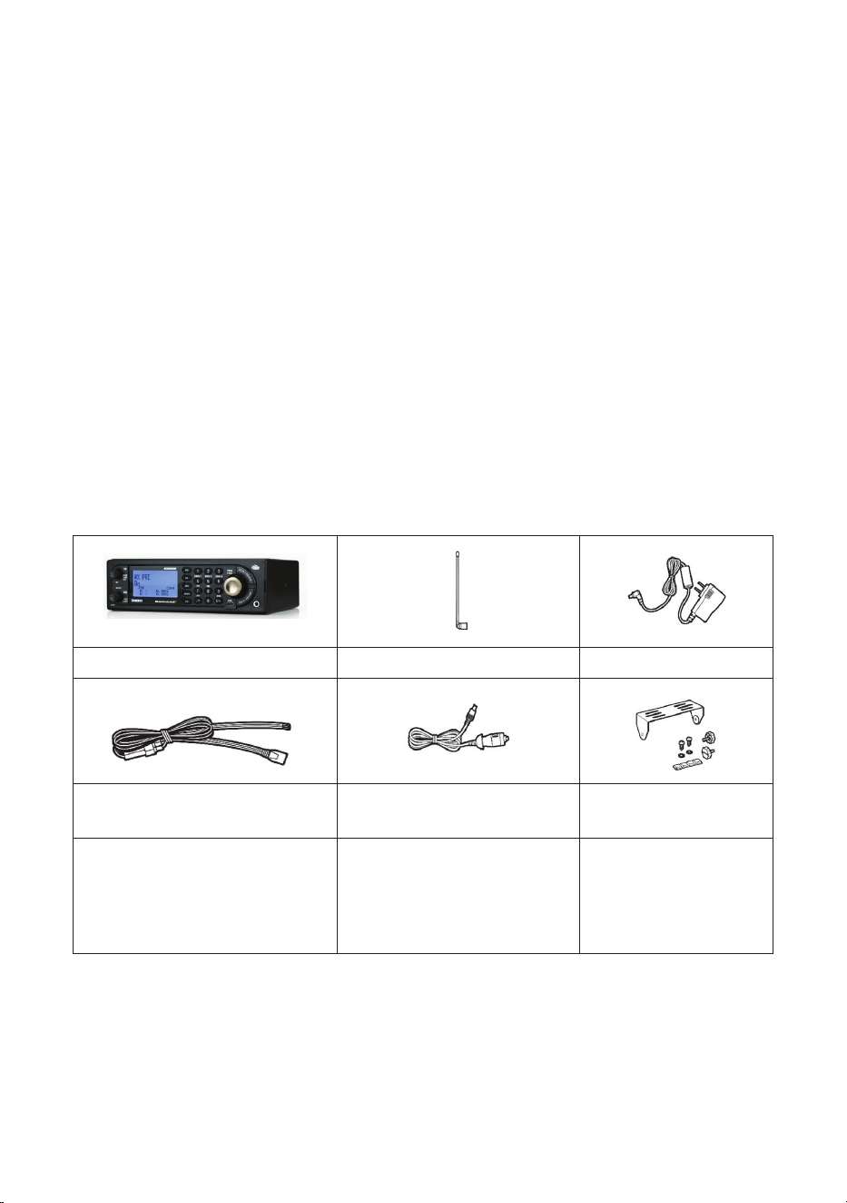
INCLUDED WITH YOUR SCANNER
Included in the box are:
BCD260DN Scanner Telescoping Antenna AC Adapter
Three-Wire Harness
Vehicle Accessory Power
Cord
Mounting Bracket
and Hardware
Printed Materials:
• Owner’s Manual (EN, FR)
• FREQ form
• APP form
Not Shown: USB cable
SCANNING BASICS
This section provides you with background on how scanning works. You don’t
really need to know all of this to use your scanner, but some background
knowledge will help you get the most from your BCD260DN.

13
WHAT IS SCANNING?
Unlike standard AM or FM radio stations, most two-way communications do
not transmit continuously. Your BCD260DN scans programmed channels until
it nds an active frequency, then stops on that frequency and remains on that
channel as long as the transmission continues. When the transmission ends,
the scanning cycle resumes until the scanner receives another transmission.
WHAT IS SCANNING?
The BCD260DN can search for active frequencies. This is different from
scanning because you are searching for frequencies that have not been
programmed into the scanner. When you select frequency bands to search,
the scanner searches for any active frequency within the lower and upper
limits you specify. When the scanner nds an active frequency, it stops on that
frequency for as long as the transmission lasts. If you think the frequency is
interesting, you can store it into one of the banks. If not, you can continue to
search.
Understanding Scanning
What is CTCSS/DCS?
Your scanner can monitor systems using a Continuous Tone Coded Squelch
System (CTCSS) and a Digital Coded Squelch (DCS) system, which allow
the squelch to open only when the tone you have programmed with a
specic frequency is received along with a transmission. CTCSS and DCS
are sub-audible tone-signaling systems sometimes referred to as PL or DPL
(Motorola’s trademarked terms for Private Line and Digital Private Line,
respectively). CTCSS and DCS are used only for FM signals and are usually
associated with both amateur and commercial two-way frequencies.
CTCSS and DCS are used for many purposes. In many cases, CTCSS and
DCS are used to restrict access to a commercial repeater, so that only those
units which transmit the correct tone along with their signal can “talk” to the
repeater. CTCSS and DCS are also used in areas that receive interference
where there are several stations with output frequencies close to each other.
When this occurs, you might hear multiple communications on the same
frequency. The stations might even interfere with each other to the point
where it is impossible to clearly receive any of the stations. Your scanner can
code each received frequency with a specic sub-audible CTCSS or DCS
frequency or code. Then, when you receive multiple signals, you only hear
the transmission with the CTCSS or DCS tone you programmed. If you do not
receive the correct tone with a signal, the scanner’s squelch remains closed
and you hear nothing.
Refer to Appendix A for tables showing the available CTCSS frequencies and
DCS codes.

14
Conventional Scanning
Conventional scanning is a relatively simple concept. Each group of users in
a conventional system is assigned a single frequency (for simplex systems) or
two frequencies (for repeater systems). Any time one of them transmits, their
transmission always goes out on the same frequency. Up until the late 1980’s,
this was the primary way that radio systems operated. Even today, there are
many 2-way radio users who operate using a conventional system:
• Aircraft
• Amateur radio
• FRS/GMRS users
• Many business radio users
When you want to store a conventional system, all you need to know are the
frequencies they operate on. When you are scanning a conventional system,
the scanner stops very briey on each channel to see if there is activity. If
there isn’t, the scanner quickly moves to the next channel. If there is, then the
scanner pauses on the transmission until it is over.
Simplex Operation
Simplex systems use a single frequency for both transmit and receive. Most
radios using this type of operation are limited to line-of-sight operation. This
type of radio is frequently used at construction job sites, and with inexpensive
consumer radios such as GMRS/FRS radios. The range is typically 1-8 miles,
depending upon the terrain and many other factors.
Repeater Operation
Repeater systems use two frequencies: one transmits from the radio to a
central repeater; the other transmits from the repeater to other radios in the
system. With a repeater-based system, the repeater is located on top of a
tall building or on a radio tower that provides great visibility to the area of
operation.
When a user transmits (on an input frequency), the signal is picked up by the
repeater and retransmitted (on an output frequency). The user’s radio always
listens for activity on the output frequency and transmit on the input frequency.
Since the repeater is located very high, there is a very large line of sight.
Typical repeater systems provide coverage out to about a 25-mile radius from
the repeater location.
UNDERSTANDING BANKS
Channel Storage Banks
To make it easier to identify and select the channels you want to listen to,
the 1,000 channels are divided into 10 channel storage banks containing
100 channels each. You could use each channel storage bank to group
15
frequencies by department, location, area of interest, or any other way you
prefer. You can listen to any or all of the banks by pressing the number keys to
turn a channel bank on and off.
Service Search Banks
This scanner is preprogrammed with many of the frequencies allocated to
Airband, CB radio, FRS/GMRS/MURS, Ham radio, Marine, Media, Military Air,
Public Safety, Racing, and Railroad. There are 10 banks allocated for these
searches that can be used just like the channel storage banks to search these
frequencies in Service Search mode.
Custom Search Banks
Custom Search Banks let you program and search 10 custom search
ranges. During a custom search, the scanner starts searching with the lowest
frequency in the search range you select to the highest frequency in the
range. You can search any or all of these ranges by turning each search bank
on or off just like channel storage banks in Search mode.
WHERE TO LEARN MORE
By itself, this manual only provides part of what you need to know to have fun
scanning – how to program and use the scanner. The website, http://www.
radioreference.com, is the Internet’s premier source for user-supported radio
system information. This web site is not afliated with Uniden Corporation.
For more information about Uniden and our other products, visit http://www.
uniden.com.
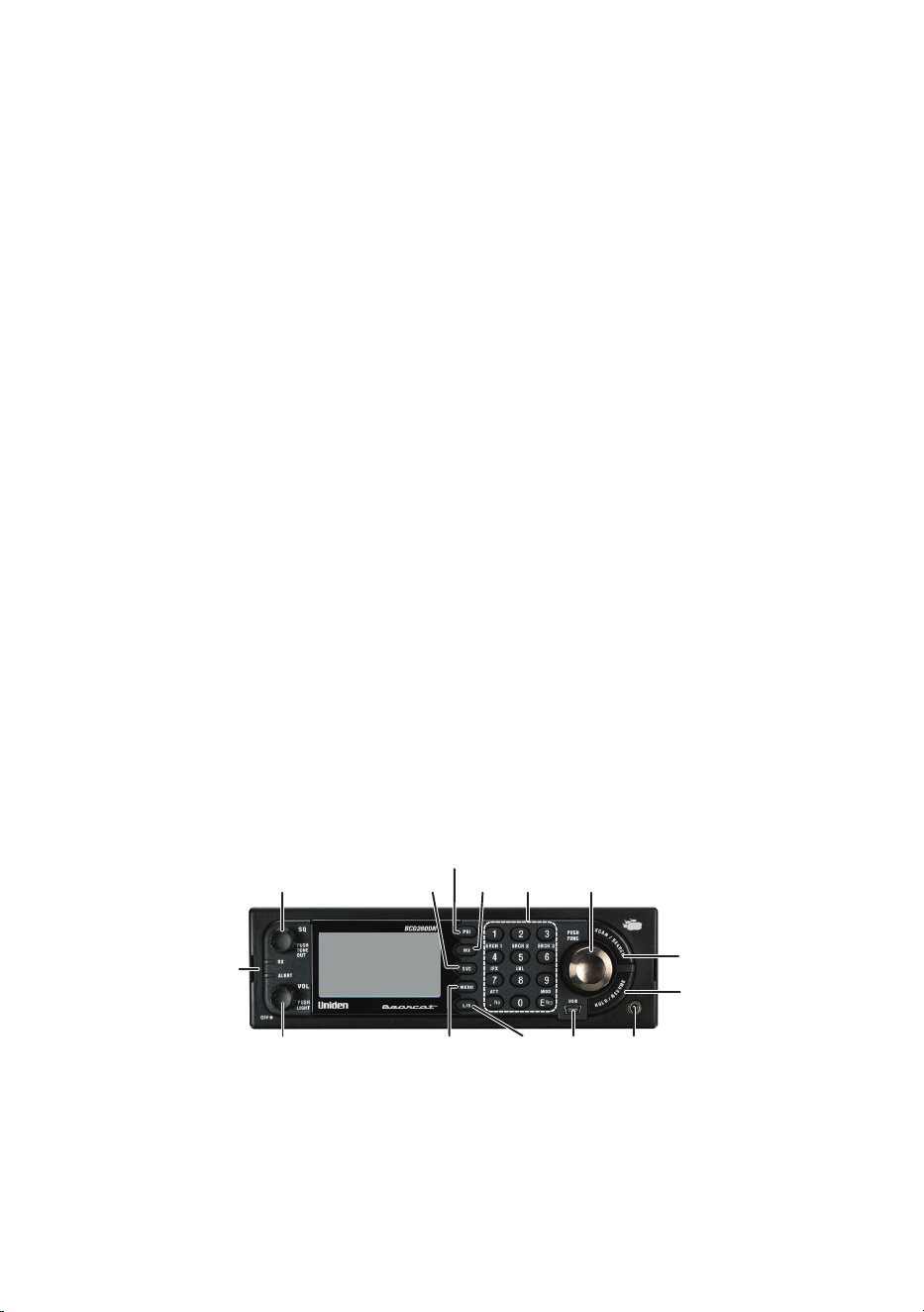
KEYPAD AND KNOB CONTROLS
BCD260DN FRONT PANEL
1
8
7
11
12
6
5
10 9
4
3
2
13
14
Each of the keys and the knobs on the BCD260DN produce different results
depending upon how you activate them. You can, for example, rotate a knob
as well as press it. Some keys provide one operation when briefly pressed
while pressing and holding a key or knob gives a different result. Many

16
controls and keys behave differently depending on the mode your radio is in
when you use them.
Number Key/Knob Function
1 SQ
(SQUELCH)
Turn knob to access and adjust Squelch.
Press knob to go to Tone-Out mode.
2 SVC
(SERVICE)
The Select Service menu displays. Select a
service and press E Yes. That service displays.
3 PRI
(PRIORITY)
Turns Priority mode on and off.
4 WX
(WEATHER)
Press to turn WX Priority mode on and off.
5 Keypad In addition to entering numbers, the 4 and 6
keys are also used to move the cursor left and
right.
Press the FUNC knob and then press one of
these numbers to access the corresponding
feature:
• 1, 2, or 3 (SRCH 1, 2, or 3)
• 4 (IFX - IF Exchange)
• 5 (LVL - Volume Offset Level)
• 7 (ATT - Attenuation)
• 9 (MOD - Modulation)
• . No - Used to enter a decimal point, delete
values, errors, and warning messages. It is
also used to select “No.”
• E Yes - Used to select, accept, and/or save a
alphanumeric value entry as well as selecting
“Yes.”

17
Number Key/Knob Function
6 Scroll or
FUNC
This knob has 2 main actions - turn to scroll,
or press to activate Function mode or save
an entry/selection. In this manual, the knob
is referred to as either the Scroll knob (if it is
rotated) or FUNC knob (if it is pressed).
Turn the Scroll knob:
• To change scan/search direction and to
continue scanning/searching in Scan/Search
modes.
• To manually scroll through channels or
frequencies in Scan/Search Hold modes.
• To scroll to a menu item in Menu mode.
• To select Tone-Outs in Tone-Out Standby
mode.
• To select characters when editing text.
Press the FUNC knob:
• To activate FUNCTION mode.
• Press and hold to lock FUNCTION mode.
Press again to release.
• To save a menu item, alphanumeric/special
character when entering text, a bank (Scan/
Scan Hold mode), or a channel/frequency.
7 SCAN/
SEARCH
• Press to start/pause scanning or searching in
Scan mode.
• Activate FUNCTION mode (press the FUNC
knob) then SCAN/SEARCH to start a quick
search.
8 HOLD/
RESUME
Press to hold on a channel or frequency in any
mode.
Press again to release the hold.
9 HEADPHONE
Jack
3.5mm Ø (Stereo Type)
NOTE: Audio does not play in stereo.
10 USB Port 5-pin mini USB B Type
11 L/O (Lock-
Out)
• Press to lock out the current channel being
monitored.
• Toggle to select: Temporary > Permanent >
Unlock > Temporary.
18
Number Key/Knob Function
12 MENU Press:
• To enter Menu mode.
• To return to previous menu.
Press the FUNC knob then Menu:
• To go to the Edit menu for the current system
in Scan mode.
• To go to the Search for... menu in Search
mode.
• To go to the WX Operation menu in any
Weather mode.
• To go to the Tone-Out for... menu in Tone-Out
Standby/Search mode.
13 VOL • Turn knob to power on the radio.
• After turning on the radio, turn the VOL knob
clockwise/counterclockwise to increase/
decrease the volume. The volume level
displays in the upper-right corner of the
screen.
• Press the knob to change the backlight level.
14 LEDs • RX - Blue when transmission signals received.
• ALERT - Red when alerts received.
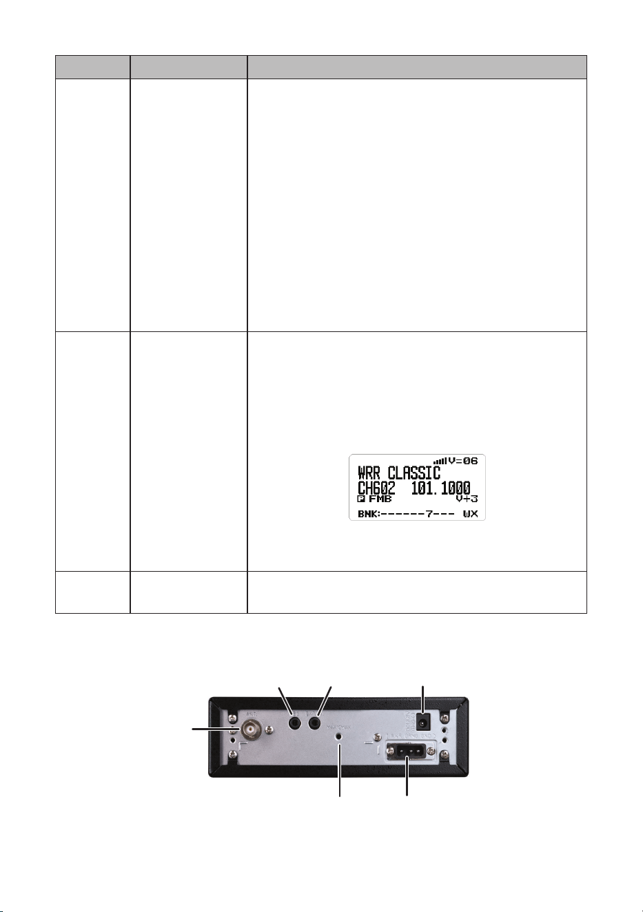
BCD260DN REAR PANEL
1
2 3 4
5
6

19
Item Description
1 Antenna Jack (50ohm BNC type)
2
Record (REC) Output Jack (3.5mm Ø Stereo* type)
3
External Speaker Jack (3.5mm Ø Monaural type)
4
DC 13.8 Volts Power Jack (5.5mm Ø Center Positive)
5 DC13.8V External Power Jack with dim control terminal for
installation on vehicle
6 Accessory Screw Hole - Maximum Depth = 10mm
* Audio output is monaural, not stereo.
BCD260DN BASIC SETUP
SETTING UP YOUR SCANNER
These guidelines will help you install and set up your new scanner:
The scanner can be placed on a convenient surface in your home as a base
station, and connected to a standard outlet that supplies 120VAC, 60Hz.
You must use either the supplied antenna or an electrically correct outdoor
antenna, properly and safely mounted at your chosen site.
The scanner is also designed to accommodate either DIN-E and ISO-DIN
automotive mounting congurations using a DIN-E sleeve and keys.
The unit can also be placed above, beneath, or in the dash of your vehicle
using the supplied bracket and mounting hardware.
• If your scanner receives interference or electrical noise, move the scanner
or its antenna away from the source.
• To improve the scanner’s reception, use an optional external antenna
designed for multi-band coverage. (You can purchase this type of antenna
at a local electronics store). If the optional antenna has no cable, use 50Ω
coaxial cable for lead-in. A BNC mating plug might be necessary for the
optional antennas.
• Use an optional stereo earphone or stereo headset with proper
impedance (32 Ω) for private listening. Read the precautions at General
Precautions.
• Do not use the scanner in high-moisture environments such as the
kitchen or bathroom.
• Avoid placing the scanner in direct sunlight or near heating elements or
vents.

20
Base Station
This is the simplest approach to let you get started quickly. Decide on a
location that is convenient to a nearby wall outlet, has desk space to let you
complete your programming worksheets, will safely allow the indoor antenna
to be extended, or near a window to use an outdoor antenna.
NOTE: Graphics in this section are for illustration purposes only and may not
reect your specic scanner.
To secure the radio to a surface, by means of the mounting bracket, follow the
steps below:
1. Attach the four protective mounting feet to the mounting bracket when
you casually use the scanner on a at surface. Should you desire to
permanently mount the scanner, remove the feet and use wood screws
through the bracket as described in Steps 2 and 3.
2. Use the bracket as a template to mark positions for the two mounting
screws.
3. At the marked positions, drill holes slightly smaller than the screws.
4. Align the bracket with the threaded holes on the sides of the radio case so
the bracket is beneath the radio. Secure the bracket using the two threaded
knobs. Never overtighten the knobs.
Once the radio is positioned, connect it to a source of AC power using the
supplied 13.8V, 750 mA AC adapter. Insert the barrel of the AC adapter to the
jack on the rear, upper right side of the radio marked “DC13.8V.” Insert the
connector of the supplied indoor telescoping antenna to the BNC Antenna
Connector and apply moderate pressure to secure it.
SETTING UP AN AUDIO OR COMPUTER RECORDING
It is best if you plan ahead when you initiate the basic setup of the scanner
if you include the components to record incoming reception. You need an
audio recording device which can be controlled by a Voice Operated module
(VOX) either externally or from within the unit and the correct connecting
cable. The REC (record) jack on the rear cabinet provides a constant-level

21
audio output which is not affected by the setting of the volume control. Use a
mono or stereo cable that ends in a 3.5mm plug for the scanner. The recorder
might have its own requirements as to the proper plug. Check the recorder’s
instructions to be sure. Connect the cable to an external or internal VOX
control so that the recorder operates when audio is present.
You can also connect the cable to the appropriate input jack on your PC so
that with controlling software, you can record to your hard disk.
In order for the function to operate, you must set the channel to record. You
must also set the system’s record option to either All Channel, which will
record all channels regardless of any channel’s setting, or Marked Channel
which only lets recording occur if you have selected record for that channel.
Which you choose will depend on various factors.
VEHICLE INSTALLATION
You can mount your scanner in your vehicle, using either the supplied bracket
or the optional DIN-E sleeve.
Mounting Using the Bracket
With the bracket removed from the radio, use the holes in the bracket as
a template to initially mark the location you plan to use in your vehicle. Be
absolutely certain of what might be behind the mounting surface before
making any holes, be it above, or below, or in front of your dash, armrest
console, or other location. If you drill carelessly, expensive damage can result.
If in doubt, consult your vehicle dealer’s service department or a qualied
professional installer.
Important: AVOID AIRBAG DEPLOYMENT ZONES. Ignoring this installation
concern may result in bodily harm and the inability of the airbag to perform
properly.
1. Using appropriate screws or other hardware, secure the bracket.
2. Insert the scanner and insert the bracket knobs to lock the scanner in
position.

22
3. Attach the Cigarette Lighter Power Cord to the rear of the scanner and plug
the adapter end into a dash mounted 12V DC socket.
4. Attach a suitable mounted mobile antenna to the antenna jack on the back
of the scanner.
Mounting Using the DIN-E Sleeve (Optional, Part No. DIN-0001)
If you are unsure about how to install your scanner in your vehicle using
the optional DIN-E sleeve, consult your automobile manufacturer, dealer,
or a qualied installer. Before installing, conrm that your scanner ts in the
desired mounting area and you have all the necessary materials to complete
the task. Your scanner requires a 2 x 7-1/8 x 5-5/16 inch (50 x 180 x 135 mm)
mounting area. Allow an additional 2-3/8 inch (60mm) space behind the unit
for connectors and wires.
1. Remove the bracket if it is attached.
2. Remove the four Philips screws from four small tabs on the rear of the case
that secure the outer metal case and pull off the case (toward the rear) with
care.
3. Install the DIN sleeve into the opening in your dashboard, lip facing out.
4. Push out the top and bottom tabs to hold the sleeve rmly in place.
5. Before inserting the scanner in the sleeve, attach the cable from the
previously mounted antenna. Attach the DC Power leads. RED goes to a
positive (+)connection on your fuse block while BLACK connects to the
vehicle’s chassis ground (-).
6. Connect the ORANGE lead to one side of the headlamp switch so that
when you activate the headlights, the scanner’s LCD display changes
intensity. Be sure all the connections are routed away from any potentially
pinching or slicing sheet metal.
7. Slowly slide the scanner into the sleeve until it locks in place.
8. To remove the unit, fully insert the removal keys into each slot on the left
and right edges of the front panel. Carefully slide the radio from the sleeve.
23
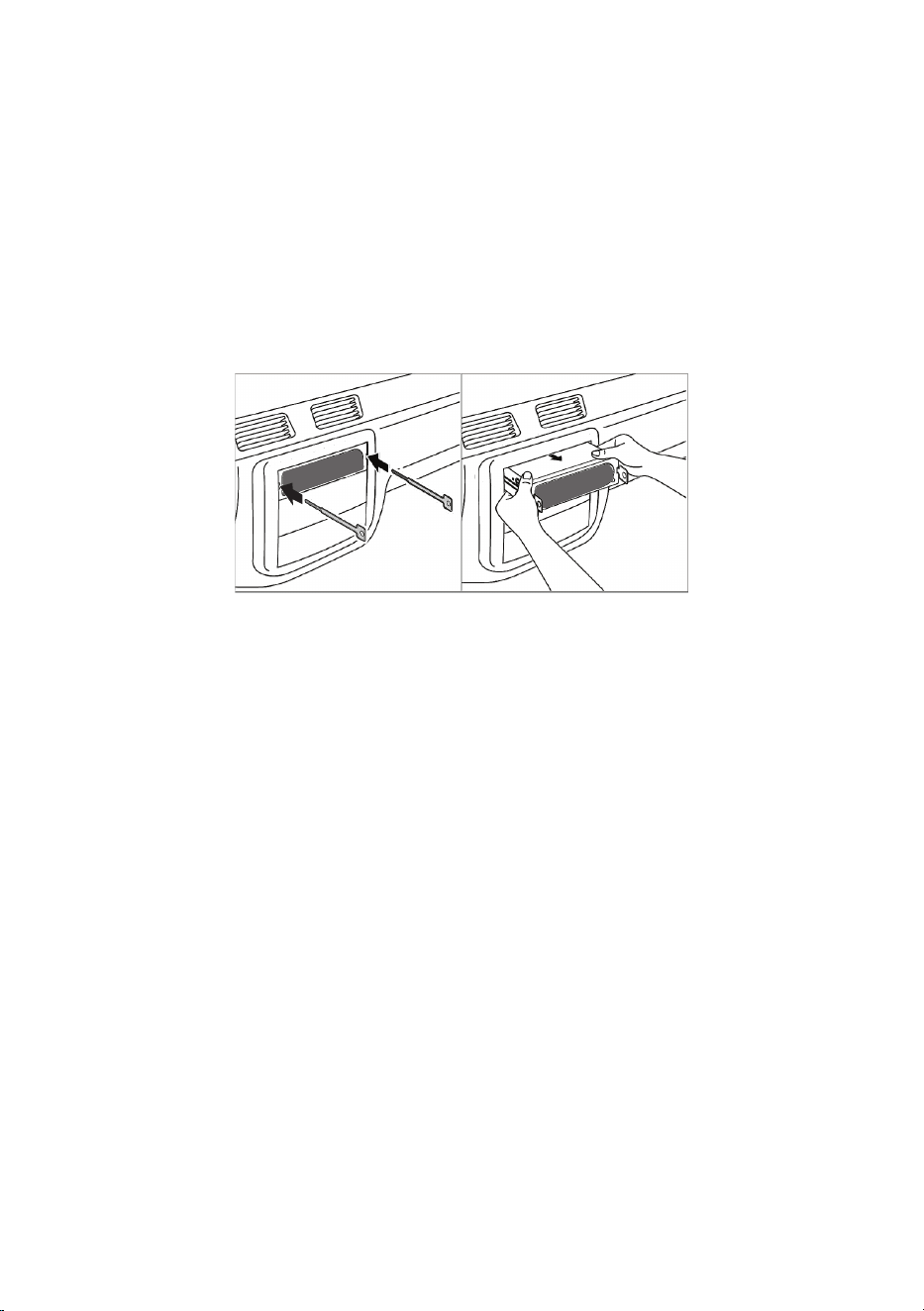
Removing the Scanner from the DIN-E Sleeve
If you plan to connect other devices or wires to the radio at a later time, you
should plan to remove the scanner from the DIN-E sleeve. This is easily done
using the provided Removal Keys that come with the optional DIN-E sleeve.
Refer to the illustration that follows, showing the Removal Keys.
Fully insert both Removal Keys into the slots on the left and the right edges
of the radio’s dress panel. You cannot remove the radio with only one key.
Press in fully, and do not twist the keys. The radio will unlock from the sleeve,
making withdrawal from the sleeve possible. Store the keys in a safe place for
future use.
Mounting Using ISO Technique
Some vehicles can take advantage of another approach to mounting a radio
in a vehicle, called the ISO technique. However, this technique requires a very
detailed and thorough knowledge of the technique. Therefore, we strongly
suggest that if you have any doubt about your experience and abilities, please
consult with a professional installer who is familiar with the ISO approach to
radio installation.
To begin the process, it is rst necessary to remove the scanner’s outer metal
sleeve from the inner chassis. Unthread the four screws in the rear of the
unit. Slide the cover toward the rear and off. Once the sleeve is removed, you
will see threaded, metric machine screw holes on either side of the chassis
cabinet. Uniden does not supply these screws. Their diameter, length, and
screw type should be chosen by a qualied installer based on the internal
vehicle bracket which will be used in securing the scanner chassis.
Once the original radio is removed from the vehicle dash and the t of the
scanner is correct, be sure to connect all the power, audio, antenna, and any
other cables or wires, to the scanner before the scanner is secured.
The following illustration is a typical example of the ISO technique and the
general side mounting screw holes often encountered. It does not actually
represent the Uniden scanner nor your vehicle’s mounting bracket. Only a
professional installer will be able to determine the best and correct approach.

24
Removing the Display Sticker
Before you use the scanner for the rst time, remove the protective plastic lm
over the display.
Connecting an Optional Antenna
The scanner’s BNC connector makes it easy to connect a variety of optional
antennas, including an external mobile antenna or outdoor base station
antenna.
Note: Always use 50-ohm, RG-58, or RG-8, BNC terminated coaxial cable to
connect an outdoor antenna. If the antenna is over 50 feet from the scanner,
use RG-8 low-loss dielectric coaxial cable. Cable loss increases with higher
frequency.
Connecting an Earphone/Headphone
For private listening, you can plug a 1/8-inch (3.5 mm) mini-plug earphone
or headphones (not supplied) into the headphone jack on the front of your
scanner. This automatically disconnects the internal speaker. See the
Earphone Warning on page 2 for important information about using an
earphone/headphone.
WARNING!
Never connect anything other than the recommended amplied
extension speaker to the scanner’s headphone jack. Damage to the
scanner might occur.
Connecting an Extension Speaker
In a noisy area, an optional amplied extension speaker, positioned in the
right place, might provide more comfortable listening. Plug the speaker cable’s
1/8-inch (3.5-mm) mini-plug into your scanner’s back panel Ext. Sp. Jack.
WARNING!
Never connect any part of the headphone jack to the antenna jack
or connect the radio to an installation where the antenna and audio
connection are grounded. This might also damage the scanner.

25
Turn on the Scanner
Rotate the VOL knob clockwise until it clicks. The scanner is now powered up
and in Volume mode. The volume level displays.
Continue rotating the VOL knob clockwise until the volume level is in the 6 - 8
range. The Uniden Welcome screen displays.
NOTE: If the scanner has been used previously, it will return to whatever
mode it was in when it was turned off. If the scanner is new or has been reset,
the radio displays Scan Mode Nothing to Scan because it has not yet been
programmed with frequencies to scan. If you want to search for something
right away, set up Volume and Squelch settings; next, press the SVC key and
select a pre-programmed service.
CONFIGURE SCANNER
After you turn on the scanner for the first time, configure it to your personal
liking by setting the volume level, adjusting the squelch level, and going to
MENU/Settings (page 79) to personalize the unit. Configuring the scanner
involves the following:
• Set volume level.
• Set squelch level.
• Set backlight.
• Set RX LED.
• Adjust key beep.
• Set Upside-Down.
• Adjust contrast.
• Adjust band default values.
Set Volume Level
1. Turn the VOL knob to display the volume level indicator in the upper right
of the screen.
2. Turn the VOL knob to adjust the volume (levels 00 - 29).
3. The volume adjust display times out after 3 seconds.
Set Squelch Level
1. Turn the SQ knob to display the squelch level in the upper right corner of
the screen.

26
2. Turn the SQ knob counter-clockwise all the way and then clockwise until
the noise stops (00 - 19 levels). Turn the SQ knob one level more.
3. The squelch adjust display times out after 3 seconds.
Set Backlight
Adjust the backlight intensity for the screen and for the keypad through the
menus or by pushing the VOL knob.
NOTE: Set the dimmer to AUTO if you are going to hard-wire your scanner
inside your vehicle.
1. From MENU/Settings, scroll to Set Backlight and press E Yes. The Set
Backlight screen displays two options: Set Dimmer and Set Color.
Scroll to Set Dimmer and press E Yes. Set Dimmer lets you determine
whether the dimmer is set automatically or manually.
If the scanner will be mounted in an automobile, select AUTO, choose
between + Polarity (the orange wire gets 12V when you turn on the
headlights) or
– Polarity (the orange wire is switched to chassis ground when you turn on
the headlights), and press E Yes. The Set Backlight menu displays again.
If the scanner is for home use and will NOT be mounted in an automobile,
select MANUAL, choose between High, Middle, Low, and Off, and press E
Yes. The Set Backlight menu displays again.
2. From the Set Backlight menu, scroll to Set Color and press E Yes. The Set
Color screen displays the following list of color options:
• Cyan
• Yellow
• White
• Blue
• Red
• Magenta
• Green

27
NOTE: The screen background changes color to the color selected as you
scroll through the color options.
3. After selecting a color, press E Yes. The Set Backlight menu displays
again.
4. Press MENU to return to the Settings menu.
Set RX LED
This menu allows the Alert LED to turn on when an alert is received.
1. From MENU/Settings, scroll to Set RX LED and press E Yes. The Set RX
LED menu displays two options: On and Off.
2. Select either On or Off and press E Yes. The system returns to the
Settings menu.
Adjust Key Beep
This setting turns key beep on and off and adjusts its volume level.
1. From MENU/Settings, select Adjust Key Beep and press E Yes.
2. Select a key beep volume level (1 - 15), Auto (the scanner sets the alert
beep to the master volume level), or Off (no sound is made).
NOTE: When you scroll through the volume level options, the scanner beeps
at that level.
3. Press E Yes to set the desired beep level and return to the Settings menu.
Set Upside-Down
This option switches the screen display upside-down. Turn this setting on or
off according to your scanner mounting position and viewing needs.
1. From MENU/Settings, select Set Upside-Down and press E Yes.
2. Select On (image is upside-down) or Off (image is normal orientation) and
press E Yes.
3. The scanner returns to the Settings menu.
Adjust Contrast
This setting controls the display’s contrast.
1. From MENU/Settings, scroll to Adjust Contrast and press E Yes.
2. Fifteen contrast levels display. The screen displays the contrast level as
you scroll through the options. Select a contrast level and press E Yes to
save it and return to the Setting menu.

28
Change Band Defaults
This setting allows you to change the “Auto” (default) values to whatever you
feel “Auto” should be for each band (vs. the radio defaults). Since all of the
step and modulation settings default to “Auto,” this allows you to skip those
settings when programming.
NOTE: These settings do not affect service searches.
1. From MENU/Settings/Band Defaults, scroll to the band you wish to edit and
press E Yes. The Set Modulation menu for that band displays.
2. Scroll to one of the following and press E Yes to select it:
• AM
• NFM
• FM
• WFM
• FMB
3. The Set Step menu displays. Scroll to one of the following options and
press E Yes to save and exit.
5
kHz
6.25
kHz
7.5
kHz
8.33
kHz
10
kHz
12.5
kHz
15
kHz
20
kHz
25
kHz
50
kHz
100
kHz
4. The Band Default screen displays again. Repeat these steps to edit other
bands. When nished editing bands and the Band Default screen displays
again, press MENU to return to the Settings menu.
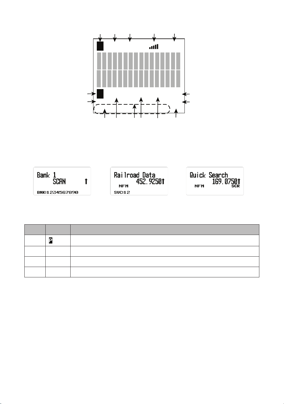
A LOOK AT THE DISPLAY
This next graphic shows the various screen elements and where they appear.
Not all elements display on every screen.
29
F
HOLD
TL/O
C67.0
P
N F M A T T I F X V + 1
DMR PRI
B N K: 1 2 3 4 5 6 7 8 9 0 WX
43 5 6 7 8
9
10
1
2
15 14 13 12 11
V=/S=
The following 3 screens are examples of different types of screens, showing
how elements from the rst graphic are displayed.
Scan Screen
Example
Service Search Screen
Example
Quick Search Screen
Example
Item Meaning
1
Priority channel
2 CTCSS/DCS/Color Code data (C67.0/DCS023/CC1, etc.)
3 BNK Bank number (1 - 9, 0)
4 Modulation Type (AM, NFM, FM, WFM, or FMB)
30
Item Meaning
5 • CAP. Capacity Plus/Linked Capacity Plus site’s voice and
data in MotoTRBO system.
• CON. Connect Plus site’s voice and data in MotoTRBO
system.
• DT3. Trunked DMR site’s voice and data in ETSI Standard
Tier 3 system.
• DMR. One frequency DMR site’s voice and data/Simplex
DMR voice.
• IDS. IDAS in NXDN system.
• ND4. NXDN 4800 Direct Frequency
• ND9. NXDN 9600 Direct Frequency
• NX4. NXDN 4800 NEXEDGE
• NX9. NXDN 9600 NEXEDGE
• NXD. Unknown NXDN system
• XPT. Hytera XPT site’s voice and data in MotoTRBO
system.
• P25/DAT. APCO Project 25 is not supported, so the
scanner skips P25 signals when searching or scanning.
NOTE: These display in the same place as the DMR icon in
the illustration and also in conventional/search mode.
6 ATT icon displays when attenuator is on.
G-ATT icon displays when global attenuator is on.
7 IFX Indicates current frequency is set to IFX (IF Exchange).
8 WX Indicates Weather Alert Priority Scan mode is on.
9 PRI PRI indicates Priority Scan mode; it blinks while the Priority
Plus scan is active.
indicates Priority Do-Not-Disturb (DND).
10 V-3/V-2/V-1/V+1/V+2/V+3. Displays when Volume Offset is
on.
11 V=
S=
Volume or Squelch level display.
12
This bar displays the received signal strength (0 - 5).
13 L/O indicates a channel or frequency is permanently locked
out.
TL/O indicates a channel or frequency is temporarily locked
out.

31
Item Meaning
14 HOLD Hold on a channel.
Press again to release hold and continue scanning.
15
Displays when the FUNC knob is pressed, indicating that the
Function mode is activated (Function mode times out in three
seconds).
Press and hold the FUNC knob longer than three seconds to
enter Function Hold mode; the icon blinks and Function Hold
mode does not time out after three seconds.
MENUS
Procedures in this manual refer to the BCD260DN’s menus for programming
channels, frequencies, banks, and other operations.
Press MENU to display the main menu list:
• Program Channel
• Search Options
• Search for . . .
• Priority Scan
• WX Operation
• Tone-Out for . . .
• Settings
Appendix B on page 72 details each menu and its subsequent submenu
structure.
USING MENUS
After pressing MENU, the main menu displays.
Turn the Scroll knob clockwise to scroll through the items in order. Turn the
Scroll knob counter-clockwise to scroll through the items in reverse order
(backwards).
ENTERING/SELECTING DATA
For screens that require input (entering a name, changing a frequency, etc),
follow these conventions:

32
To enter a character, turn the Scroll knob until the character you want displays.
Characters display in the following order: all capitals, all lower case, numbers,
specials, blank. Press E Yes to select it.
• To move the cursor to the left, press 4.
• To move the cursor to the right, press 6.
• To clear a character, press . No.
• To clear all characters, press . No twice.
• To save and exit when nished, press E Yes.
There are 2 ways to select the item you’ve chosen:
• Press E Yes.
• Press the FUNC knob
NOTE: This manual uses “Press E Yes” but either method will take you to the
appropriate menu level.
Valid Frequency Ranges
When you program channels into a bank, you assign frequencies to that
channel. The supported band frequency range is from 25.000 to 1300.000
MHz, with two ranges not supported: 513.0000 – 758.000 and 823.9900 –
849.0100.
The scanner automatically rounds the entered number to the nearest
supported step. For example, if you enter 151.473 MHz, the scanner rounds it
to 151.475.
BCD260DN OPERATION SETUP
You must program at least one frequency into a channel before you can begin
scanning. To customize your scanner, you should also:
• Set up and program channels into banks.
• Set up search (frequency) ranges.
• Set up search characteristics such as service list names, delay times, etc.
• Set up custom searches.
• Set up quick searches.
• Set up weather features.
When you have congured your scanner, you can start using your scanner’s
preprogrammed service banks, the custom search banks, or the Weather
Scan/Alert feature.
33
PROGRAM CHANNELS
NOTE: See SEARCH MODE (page 38) if you want to continuously search
all or specic ranges of frequencies or preprogrammed service frequencies
instead of scanning programmed channels.
Before scanning for transmissions, you need to set up channel banks and
program frequencies into those channels. You can save 100 channels into
each of the 10 channel banks (1000 channels total). If desired, group similar
channels into one bank to make listening easier, and name the channels/set
attributes for each channel.
After programming channels into banks, press SCAN/SEARCH to scan those
entries. The scanner starts scanning at Bank 1 and continues through Bank
10 (displays as BANK 0) before repeating the scanning process. Flashing
numbers at the bottom of the screen indicate which bank is currently being
scanned. If there are banks you do not want to scan, press that bank’s number
to turn it off. Press that number again to turn it back on and make it available
for scanning.
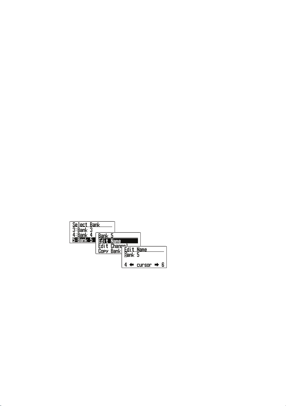
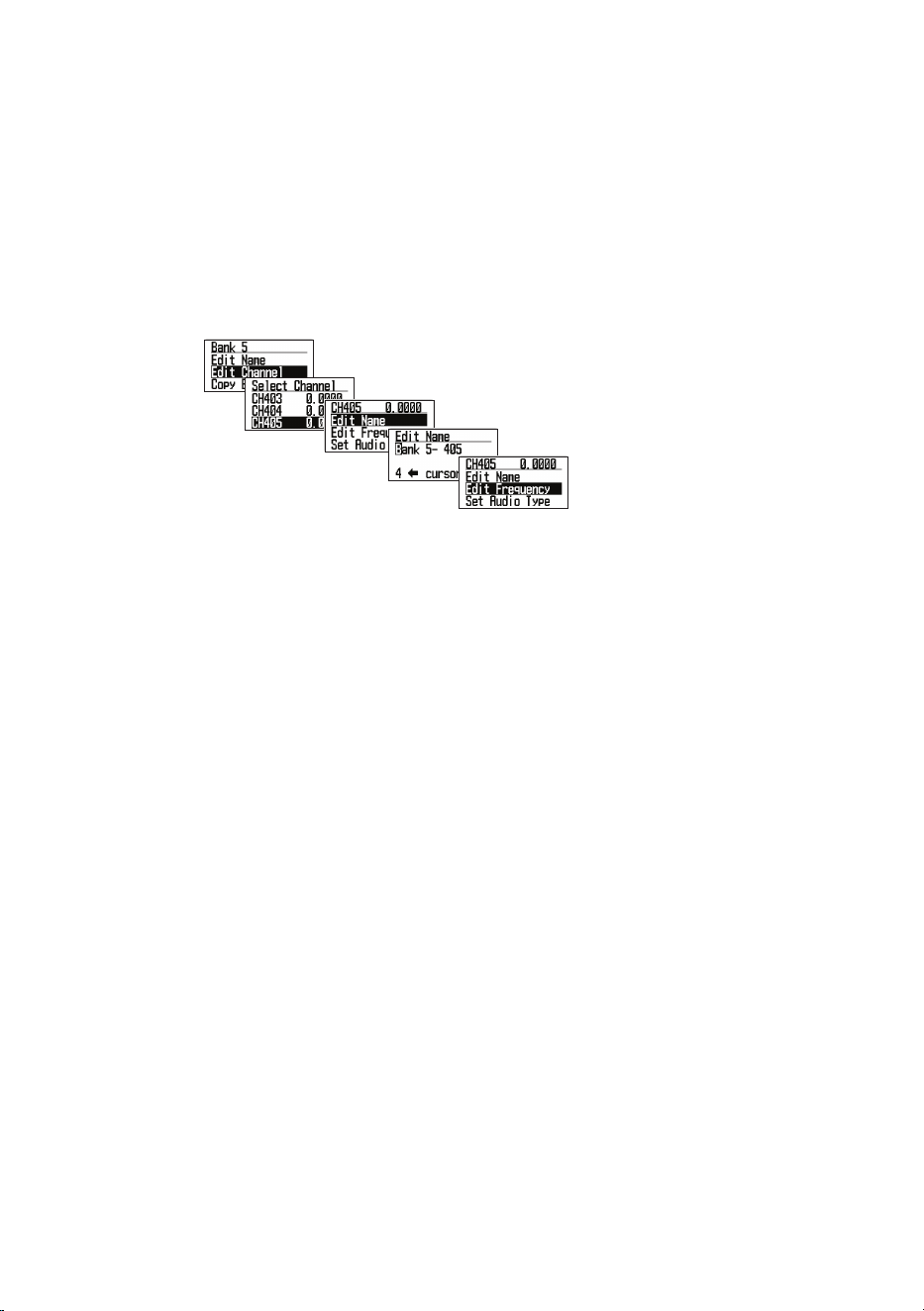
Editing Banks and Channels
1. From MENU/Program Channel/Select Bank, you can select a bank and
rename it.
After entering a new
bank name, press
MENU to return to the
previous screen. Select
Edit Channel.
From MENU/Program Channel/Select Bank -
2. Select Bank. You can select from 1 (Bank 1) through 9 and 0 (Bank 9 and
Bank 10).
The rst number (1, 2, etc) is the Bank number (Bank 1, Bank 2, etc) that
matches the number on the bottom of the screen when scanning begins.
CAUTION: Frequencies must be registered in these banks before
scanning can start. Nothing to Scan displays if you try to scan an empty
bank.
3. Edit Name. After you select a bank and press E Yes to set it, that bank’s
action list displays. If you do NOT want to change the Bank’s name, the
bank name will default to Bank 1, Bank 2, etc, If you DO want to change
34
the bank’s name, select Edit Name. Refer to page 31 for text entry
procedures.
NOTE: The bank name appears at the top of the screen while scanning.
For example, if you put the frequencies for Public Safety in 1:Bank 1 and
renamed it to 1:Public Safety, you can see what services are scanning in
BNK:1.
After you have selected a bank and renamed it if desired, you can select a
channel in that bank and edit it.
After entering a new channel
name, press MENU to return
to the previous screen.
Select Edit Frequency.
4. Edit Channel. The Select Channel screen displays. Select a channel to
edit. That channel’s 13 editable settings display:
• Edit Name. You can set a name for the channel and change it as
needed. If you do not edit the channel name, it will default to “BANK
1-001, etc.”
NOTE: When a frequency is received and scanning stops, the name of that
channel displays on the screen.
• Edit Frequency. Enter a frequency within the frequency range
supported by this radio. Decimal numbers may be rounded depending
on the frequency; it does not affect performance.
NOTE: The scanner automatically rounds the entered number to the nearest
supported frequency. For example, if you enter 151.473 MHz, the scanner
rounds it to 151.475. See page 32 for valid frequency details.
NOTE: Check websites for frequencies that can be received in your area.
Uniden recommends visiting www.radioreference.com, which has a lot
of information about scanner radios and frequencies. You can also use a
scanner shop that offers a service (for a fee) that programs frequencies for
your location into your scanner.
• Set Audio Type. Select one of the three following audio types: All, Digital
Only, and Analog Only.

35
ALL: The radio will automatically detect the signal and receive it in the
appropriate mode. Select ALL if you don’t know what mode is being used
for that frequency.
IMPORTANT: In this mode for any signal, the radio outputs audio and
stays on that frequency for as long as the received signal lasts. Even for
a digital signal that cannot be demodulated or a control signal that does
not contain sound, the radio recognizes it as analog signal so that, after
receiving it, the radio stays on that channel until the signal disappears.
If you know that digital communication is used on this signal, it is highly
recommended that you set Audio Type to Digital Only.
Digital Only: The radio will scan assuming only digital signals are
coming. Digital communications that cannot be demodulated and data
signals (such as control signals) are ignored; scanning resumes after data
channel signals are received.
Select Digital Only and the following options display in the Code Option
menu: Search, Set Color Code (0 - 15), Set NEXEDGE RAN (0 - 63), and
Set IDAS Area (0, 1).
Caution: It may appear that the Squelch setting is not effective in
Digital Only mode as there is no apparent change when adjusting
the Squelch level. However, during scanning, the Squelch setting
value is indeed used to determine the presence or absence of a
signal.
If you start scanning with the squelch set to open, it would require
checking each time as to whether or not there is a digital signal that
can temporarily pause and demodulate even on channels without a
signal.
This would slow down the scanning process. Therefore, before
starting scanning in Digital Only mode, always ensure that the
squelch is not set to open.
It is recommended to either set the squelch value to the level used
when receiving analog signals or pre-set the squelch level to around
2 or 3 before starting the scan.
Digital code search and ltering by Color Code, RAN code, and IDAS
Area are possible.
Analog Only: The radio will scan assuming only analog signals are
coming.
- Since the digital signal is not demodulated, it becomes data sound.
- Squelch is enabled. Check the Squelch level.
- CTCSS/DCS included in the received signal can be searched and
ltered.

36
Select Analog Only and the following options display in Set CTCSS/
DCS menu: Search, CTCSS, and Set Lockout.
• Set Modulation. When you select AUTO, the radio will use the default
mode for that selected frequency.
If you want to intentionally change the mode and bandwidth, you can
change it manually.
Press the FUNC knob + 9 MOD during Scan Hold mode to override
modulation.
• Set Delay Time. Scroll to the desired delay time and press E Yes to save
and exit.
- 0, 1, 2, 5, 10, 30 seconds. Sets the time to stay on that frequency
after transmission ends. Doing this lets you wait for a delayed reply
to that transmission. If set to 0, the scan will start as soon as the
transmission ends; if there is a reply after 1 second, you may miss it.
Increasing this time will slow down the overall scan time.
- -2, -5, -10, -30 seconds. If set to a negative value on that frequency,
the radio stays on that frequency for the set amount of time after
receiving a signal. For example, if you select -2 seconds, you will only
hear the rst 2 seconds of a 10 second transmission.
• Set Attenuator Add attenuation per individual frequency. Attenuation can
also be set globally.
If a strong signal source exists near the desired frequency, it may interfere
with reception of the desired frequency. Turning ATT ON weakens the
received signal but may improve communication clarity. Under normal
circumstances, use it with OFF.
- Press the FUNC knob + 7 ATT
to override this setting during Scan/
Hold mode.
- Press and hold the FUNC knob + 7 ATT to toggle global attenuator.
• Set Priority. Select On to set this channel as a Priority Channel or Off
to deselect it. See the Priority Scan section beginning on page 49 for
more details.
• Set Alert. You can program your scanner to alert you when a channel is
received. For each alert in the scanner, you can select from 9 different
tone patterns, 15 volume settings, 7 colors, and 2 color patterns.
- Set Alert Tone. Choose from 9 alert sounds (1 - 9) or Off. The radio
sounds each tone as it is selected. After selecting the tone, Set Level

37
displays. Select a volume level (Auto, 1 - 15). Set Alert displays
again.
- Select Set Alert Light. The radio’s Alert Light (LCD Backlight) turns
on/blinks according to this setting when this frequency is received.
If the backlight setting is:
* Off - the LCD Alert backlight turns on in the selected color for 5
seconds.
* On - the LCD Alert backlight will be overwritten with the specied
color for 5 seconds.
* Slow Blink. The LCD Alert backlight blinks slowly up to three times.
* Fast Blink. The LCD Alert backlight blinks up to 5 times in short
intervals.
NOTE: The LCD backlight color preset for normal use will be overridden
by the color set here; please select a color different from the backlight
color you normally use.
• Set Record. Selecting On enables the scanner to output audio signals to
an external audio recording device. Off prevents audio signal output.
• Set Lockout. Setting a frequency to Lockout will skip that frequency
when scanning.
- Unlocked: Unlocks a locked out frequency. Invalid if selected for an
already unlocked frequency.
- Temporary L/O. Locks out a frequency if it is unlocked (see Unlock
above) or power cycles to the radio. TL/O frequencies are not
retained in memory.
- Lockout (L/O): Locked out until it is unlocked (see Unlock above). L/O
status is saved to memory when power cycles.
• Adjust Volume Offset. Fine-tune the audio level for each receiving
frequency. The audio level may differ depending on the communication
received. You can manually atten the receiving audio level difference for
each frequency. Volume offset values are: -2, -1, 0, +1, +2, and +3.
Press the FUNC knob + 5 LVL during Scan Hold mode to override
Volume Offset.
• Set Digital Waiting. Set the amount of time for the scanner to determine
if a transmission is digital or analog. During this time, the scanner
evaluates the signal and, if it detects a digital signal, it immediately opens
squelch. If a digital signal is NOT detected before the delay expires, the
scanner opens squelch at the end of the delay. This prevents “false
decode” problems (digital noise at the beginning of transmissions). The
default setting is 400 ms. This setting only affects channels with an Audio

38
Type set to ALL.
NOTE: For analog transmissions, if the Audio Type is set to ALL, the rst
part of the transmission will be lost for the wait time set here.
• Clear Channel. Clear a specic channel. The cleared channel becomes
an empty channel (0.0000 MHz), and is locked out and excluded from
scanning.
5. Copy Bank. You can copy the contents of a bank that has already been
created and paste it into another bank.
• Scroll to the bank you want to copy and select it.
• Next, select Copy Bank from the Select Bank menu.
• Select the bank you want to paste the bank information into and press E
Yes to overwrite it.
NOTE: The Bank name is not copied; please rename it after copying.
6. Clear Bank. Erases the contents of the bank and returns it to factory
default settings.
SEARCH MODE
Setting up search ranges lets you search for pre-programmed frequencies.
There are three types of searches:
• Service Search. Search for pre-programmed service frequencies (police,
re, civil air, etc).
• Custom Search. Set lower- and upper-frequency limits and other search
criteria.
• Quick Search. Start searching at the displayed frequency or at a specic
entered frequency
Service Search
If you do not have a reference for frequencies in your area, use an internet
search to nd transmissions. You can search for Airband, CB radio, FRS/
GMRS/MURS, Ham radio, Marine, Media, Military Air, Public Safety, Racing,
and Railroad frequencies without knowing the specic frequencies in your
area. The scanner’s service lists are preprogrammed at the factory with all the
frequencies allocated to those services.
SVC
List
Name SVC
Bank 1
SVC
Bank 2
SVC
Bank 3
SVC
Bank 4
SVC
Bank 5
SVC
Bank 6
SVC
Bank 7
1 Public
Safety
Pub.
Safety
LOW
Pub.
Safety
HI
Pub.
Safety
UHF
Pub
Safety
800
2 Media Media

39
SVC
List
Name SVC
Bank 1
SVC
Bank 2
SVC
Bank 3
SVC
Bank 4
SVC
Bank 5
SVC
Bank 6
SVC
Bank 7
3 Ham
Radio
Ham
Radio
10m
Ham
Radio
6m
Ham
Radio 2m
Ham
Radio
1.25m
Ham
Radio
70cm
Ham
Radio
33cm
Ham
Radio
23cm
4 Marine Marine
USA
5 Railroad Railroad
STD
Railroad
SPLT
Railroad
Data
6 Air Band Airband
8.33K
7 CB Radio CB
Radio
AM
8 FRS/
GMRS/
MURS
FRS/
GMRS/
MURS
9 Racing Racing
10 FM
Broad-
cast
FM
Broad-
cast
11 Military
Air
Military
Air
12 Custom 1
13 Custom 2
14 Custom 3
There are three ways to start a Service Search:
• Press SVC to display a list of services. Select the service you want and
press E Yes.
• Press MENU/Search for .../Service Search to display a list of services.
Select the service you want and press E Yes.
• Assign a specic service to a SRCH key in advance; press the FUNC
knob and then the SRCH 2 key to start. (See page 48.)
NOTE: Factory preset SRCH 2 is preset to Public Safety. Press the FUNC
knob and then SRCH 2 to start searching Public Safety channels.
The Public Safety channels themselves are divided into four bands by
frequency band and assigned to SVC Banks 1, 2, 3, and 4. SVC: 1 2 3 4
displays on the bottom line of the screen.
• SVC:1 = Pub. Safety LOW

40
• SVC:2 = Pub. Safety HI
• SVC:3 = Pub. Safety UHF
• SVC:4 = Pub. Safety 800
NOTE: Disabled or empty service bank numbers are not displayed. The
currently searched bank number ashes. You can turn service banks on/off by
using the 1-9/0 keys; however, one service bank must be enabled. An error
tone sounds if you try to disable the last remaining bank number.
NOTE: You can change the names and combinations of service lists; however,
the frequencies registered for each service cannot be edited. Also, modulation
for each service cannot be overridden by pressing FUNC + 9 MOD key.
When the scanner nds a transmission, it stops on it. When the transmission
ends, the scanner resumes searching according to the delay setting (see page
41).
During a service search, the upper line displays the current service name. The
lower line displays the search frequency and the direction indicator (↑ and ↓).
Service Search Receive/Hold Modes
To hold on a frequency, press HOLD. To step through the frequencies, turn the
Scroll knob while in Hold mode. Press HOLD again to resume scanning.
While monitoring a transmission, the upper line displays the current service
bank name. The lower line displays the channel name (if dened) and current
frequency with the direction indicator (↑ and ↓).
Any CTCSS/DCS received (if enabled) also appears in the display. To store
a frequency, press E Yes. To temporarily lock out a frequency, press L/O.
To permanently lock out a frequency, press L/O twice quickly. See also Edit
Custom Search Options on page 43 for Delay, CTCSS/DCS settings, and
locking out/reviewing/unlocking frequencies.
Set Service Lists
1. Go to MENU/Search For.../Set Service List (see page 74). A preset list of
11 services displays (Public Safety, Media, Ham radio, etc) plus 3 custom
lists (blank).
2. Scroll to the service list you want to edit, and press E Yes to select that
service list.
3. Two menu options display: Edit Name and Select Service.
Edit Name
Select this menu option to change the service list’s name.
1. Select Edit Name. The Edit Name screen displays.

41
2. Edit the name. Refer to page 31 for text entry options. Press E Yes when
complete.
3. The new Bank name displays at the top of the screen while searching.
Select Service
Select up to 10 services to be included from a list of the available services for
the service selected in Set Service List previously and assign them to a bank.
1. Scroll to the bank you want to change or add. Press E Yes to display the
bank’s service list.
2. Select the service to assign to that bank from the service list and press E
Yes. You can also select (BLANK) when not assigning service to the bank.
Bank numbers with blank assignment are not displayed.
3. Press MENU twice to return to the Service List menu.
Edit Service
You can congure the following settings for each service:
• Set Delay Time
• Set Attenuator
• Set Record
• Digital Waiting
NOTE: Unlike Scan mode, these settings are per service, not per frequency.
Set Delay Time
For: 0, 1, 2, 5, 10, 30 seconds:
Sets the time to stay on that frequency after the transmission ends.
NOTE: You can wait for a delayed reply to that transmission. If set to 0,
scanning starts as soon as transmission ends; if there is a reply after 1
second, you may miss it. Increasing this time will slow down the overall scan.
For: -2. -5, and -10 seconds:
If negative values are set for a frequency, the scanner stays on that frequency
for the set amount of time after receiving a signal. For example, if you set
this value to -2 seconds, you will only hear the rst 2 seconds of a 10-second
transmission.
Scroll to the desired delay time and press E Yes to save and exit.

42
Set Attenuator
Add an attenuator per frequency.
If a strong signal source exists near the desired frequency, it may interfere
with reception of the desired frequency. Turning on ATT weakens the received
signal; but it may also improve communication clarity. Normally, use it with
OFF.
NOTE: Press the FUNC knob + 7 ATT to set attenuator for individual
frequencies. Press and hold the FUNC knob + 7 ATT to set global attenuator.
Set Record
This setting allows a live audio output from the Record Out Jack (REC) to an
audio recording device.
On — the scanner outputs the audio signal.
Off — the scanner does not output any audio signals.
Set Digital Waiting
This setting gives the scanner time to determine if a transmission is digital or
analog. During this time, the scanner evaluates the signal and, if it detects a
digital signal, it immediately opens squelch. If a digital signal is not detected
before the delay expires, the scanner opens squelch at the end of this
delay. This prevents “false decode” problems (digital noise at the beginning
of transmissions). The default setting is 400 ms. This setting only affects
channels with an Audio Type set to ALL.
NOTE: Any analog transmissions on channels with Audio Type set to ALL will
lose the rst part of the transmission, up to the wait time set here.
Custom Search
Setting up a custom search allows you to edit the 10 custom search ranges.
Default custom search range names display as Custom 1, Custom 2, etc.
Custom 1 refers to SRCH Bank 1 (SRC:1), Custom 2 to SRCH Bank 2 (SRC:
2), etc. These Search bank numbers match the number displayed at the
bottom of the screen when starting Custom Searches.
The default search frequency ranges are:
• Custom 1 (SRC:1) 25.0000MHz to 27.9999MHz
• Custom 2 (SRC:2) 28.0000MHz to 29.6999MHz
• Custom 3 (SRC:3) 29.7000MHz to 49.9999MHz
• Custom 4 (SRC:4) 50.0000MHz to 53.9999MHz
• Custom 5 (SRC:5) 137.0000MHz to 143.9999MHz
• Custom 6 (SRC:6) 144.0000MHz to 147.9999MHz
• Custom 7 (SRC:7) 406.0000MHz to 419.9999MHz
• Custom 8 (SRC:8) 420.0000MHz to 449.9999MHz

43
• Custom 9 (SRC:9) 450.0000MHz to 469.9999MHz
• Custom 10 (SRC:10) 806.0000MHz to 960.0000MHz
Edit Custom Search Options
1. Select MENU/Search for.../Edit Custom. A list of the 10 search banks
displays.
2. Scroll to the search bank you want to edit and press E Yes. A list of options
to edit displays:
• Edit Name
• Edit Srch Limit
• Set Step
• Set Delay Time
• Set Modulation
• Set Attenuator
• Set Record
• Digital Waiting
Edit Name
NOTE: If you do not want to change the bank name, skip this option. The bank
name displays the default Custom 1, Custom 2, etc.
1. Select Edit Name from the list of available editing options. The Edit Name
screen displays with the name of the Search Bank displayed and the rst
character highlighted. Refer to page 31 for text entry options.
2. Press E Yes when you have nished editing to save the entry, exit, and
return to the previous menu. The new name displays on the top of the
screen while searching.
Edit SRCH (Search) Limit
This search option lets you set the lower and upper frequencies to be
searched. Be careful to enter the frequency correctly per the information on
page 31.
1. Select Edit Srch Limit from the list of available editing options. The Set
Lower Limit screen displays the lower limit frequency with the rst number
highlighted.

44
2. Enter the new lower frequency on the keypad. The entered numbers
display as you press them.
• To move the cursor to the right one character, turn the Scroll knob
clockwise.
• To move the cursor to the left one character, turn the Scroll knob counter-
clockwise.
• To clear a character, press . No.
• To clear all characters, press . No twice.
3. Press E Yes when you have nished editing to save the entry, exit, and
display the Set Upper Limit screen.
4. Enter the new upper frequency on the keypad. The entered numbers
display as you press them.
5. Press E Yes when you have nished editing to save the entry, exit, and
return to the previous menu.
Set Step
1. Select Set Step from the list of available editing options and press E Yes to
select it. The Set Step screen displays a list of steps in KHz to select.
Auto 5 KHz 6.25 KHz 7.5 KHz
8.33 KHz 10 KHz 12.5 KHz 15 KHz
20 KHz 25 KHz 50 KHz 100
KHz
2. Scroll to the step you want to set. Press E Yes when you have nished
editing to save the entry, exit, and display the previous menu.
Set Delay Time
For: 0, 1, 2, 5, 10, 30 seconds:
Sets the time to stay on that frequency after the transmission ends.
NOTE: You can wait for a delayed reply to that transmission. If set to 0, the
search starts as soon as transmission ends; if there is a reply after 1 second,
you may miss it. Increasing this time will slow down the overall search but
allow time for a reply to be heard.
For: -2. -5, -10, -30 seconds:

45
If negative values are set for a frequency, the scanner stays on that frequency
for the set amount of time after receiving a signal. For example, if you set
this value to -2 seconds, you will only hear the rst 2 seconds of a 10-second
transmission.
Scroll to the desired delay time and press E Yes to save and exit.
Set Modulation
When you select AUTO, the radio uses the default mode for that frequency. If
you want to specically change the mode and bandwidth, you can change it
manually. Modulation options are:
• Auto
• AM
• NFM
• FM
• WFM
• FMB
NOTE: Press the FUNC knob + 9 MOD in Search mode to override
modulation.
Set Attenuator
Press the FUNC knob + 7 ATT to turn on attenuation for an individual search
bank.
If a strong signal source exists near the desired frequency or at the image
frequency, it may interfere with the desired frequency’s reception. Turning on
ATT weakens the received signal but may improve communication clarity.
Normally, use it with OFF.
Press and hold the FUNC knob + 7 ATT to toggle global attenuators.
NOTE: During a search, press the FUNC knob + 7 ATT to override this
setting.
Set Record
This setting allows a live audio output from the Record Out Jack (REC) to an
audio recording device.
On — the scanner outputs audio signals.
Off — the scanner does not output any audio signals.
Set Digital Waiting
This setting gives the scanner time to determine if a transmission is digital or
analog. During this time, the scanner evaluates the signal and, if it detects a
digital signal, it immediately opens squelch. If a digital signal is not detected
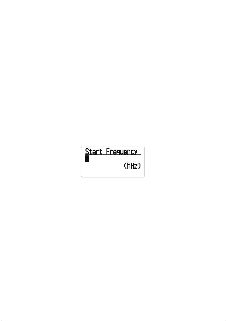
46
before the delay expires, the scanner opens squelch at the end of this
delay. This prevents “false decode” problems (digital noise at the beginning
of transmissions). The default setting is 400 ms. This setting only affects
channels with an Audio Type set to ALL.
NOTE: Any analog transmissions on channels with Audio Type set to ALL will
lose the rst part of the transmission, up to the wait time set here.
Quick Search
Set a starting frequency to begin a search. There are two methods to start a
Quick Search:
Method 1:
1. Press HOLD while the radio is scanning or searching to stop it on a specic
frequency.
2. Press the FUNC knob + SCAN/SEARCH to begin scanning from that
frequency. Turn the Scroll knob to change search directions.
Method 2:
1. Select MENU/Search for.../Quick Search. The Start Frequency screen
displays.
2. Enter the beginning search frequency and press E Yes to set it. The radio
begins scanning.
When you enter a frequency to start a quick search, the scanner automatically
rounds the entered number up to the nearest valid frequency. For example, if
you enter 151.473 MHz, the scanner starts searching at 151.475 MHz.
However, if you enter an invalid frequency, Out of Band displays and the
scanner beeps three times. Press any key to go back to the previous screen
and enter a valid frequency. See page 32.
NOTE: Use the Scroll knob to move the cursor to edit the frequency one
number at a time or press . No twice to delete the entire frequency and enter a
valid one. You can also turn the Scroll knob to change the search direction.
Set Quick Search
Select Set Quick Search from MENU/Search For... to establish search
parameters (delay time, attenuation, digital recording access, and digital
waiting). These settings are per service, not per frequency.

47
Set Delay Time
For: 0, 1, 2, 5, 10, 30 seconds:
Select the time to stay on that frequency after the transmission ends. Press E
Yes to save and exit.
NOTE: You can wait for a delayed reply to that transmission. If set to 0, the
search starts as soon as transmission ends; if there is a reply after 1 second,
you may miss it. Increasing this time will slow down the overall search.
For: -2. -5, -10, -30 seconds:
If negative values are set for a frequency, the scanner stays on that frequency
for the set amount of time after receiving a signal. For example, if you set
this value to -2 seconds, you will only hear the rst 2 seconds of a 10-second
transmission.
Scroll to the desired delay time and press E Yes to save and exit.
Set Attenuator
Push the FUNC knob + 7 ATT to add attenuation to Quick Search.
If a strong signal source exists near the desired frequency or at the image
frequency, it may interfere with reception of the desired frequency. Turning
on attenuation weakens the received signal but may improve communication
clarity. Normally, use it with OFF.
Push the FUNC knob + 7 ATT again to toggle the attenuator ON/OFF; push
and hold the FUNC knob + 7 ATT to toggle global attenuation.
Set Record
This setting allows a live audio output from the Record Out Jack (REC) to an
audio recording device.
• On — the scanner outputs audio signals.
• Off — the scanner does not output any audio signals.
Set Digital Waiting
This setting gives the scanner time to determine if a transmission is digital or
analog. During this time, the scanner evaluates the signal and, if it detects a
digital signal, it immediately opens squelch. If a digital signal is not detected
before the delay expires, the scanner opens squelch at the end of this
delay. This prevents “false decode” problems (digital noise at the beginning
of transmissions). The default setting is 400 ms. This setting only affects
channels with an Audio Type set to All.
NOTE: Any analog transmissions on channels with Audio Type set to ALL will
lose the rst part of the transmission, up to the wait time set here.

48
Set SRCH 1 - 3 Keys
The scanner has three SRCH keys to which you can assign special search
ranges. The search keys are set to number keys 1, 2, and 3. This allows you
to start a custom search, weather channel scan, tone-out search, or band
scope service search without having to go into the menus.
1. To program a Search key, press MENU.
2. Scroll to Search for... and press E Yes.
3. Scroll to Set SR1-3 Keys and press E Yes.
4. At Select SR Key, select a SRCH key (SRCH 1, SRCH 2, or SRCH 3) and
press E Yes.
5. The Select Item screen displays the SR key’s programmable options:
• (Not Assign)
• Custom Search
• Weather Channels
• Tone-Out
• Band Scope
• Public Safety
• Media
• Ham Radio
• Marine
• Railroad
• Airband
• CB Radio
• FRS/GMRS/MURS
• Racing
• FM Broadcast
• Military Air
• Custom 1 - 3
6. Select an option for the SRCH key and press E Yes.
7. Repeat for any other SRCH keys you want to program.
Default settings are:
• SRCH 1: Custom 1
• SRCH 2: Public Safety Search
• SRCH 3: Band Scope Mode
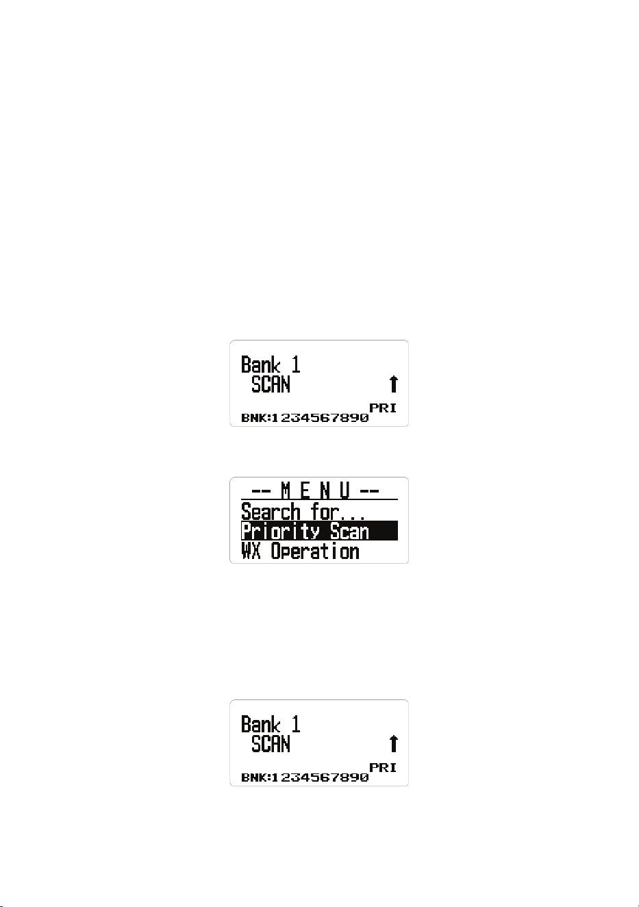
49
NOTE: If you want to leave a SRCH key blank (unassigned), select Not
Assign. An error tone sounds if you select a SRCH key that has nothing
assigned.
PRIORITY SCAN
NOTE: Set up channels rst to be Priority channels in order to use Priority
Scan. See page 36 to set a channel as a Priority channel. Priority Scan
works in both Scan and Scan Hold mode.
Based on the priority check interval setting (see page 50), the BCD260DN
interrupts scanning banks to check priority channels for activity. The more
priority channels, the longer the interruption. The scanner cannot scan
over 100 priority channels at the same time. The bank(s) containing priority
channels need to be enabled and unlocked or the scanner displays Priority
Scan No Channel and an error tone will sound. Press any key to return to
scan mode.
Hold on a channel or frequency. Then, from MENU, select PRIORITY SCAN.
Set Priority
Select one of the following Priority Scan modes:
• Off: The Priority feature is off.
• On: The scanner checks priority channels every 2 seconds. The PRI icon
displays.
• Plus On: The scanner only scans priority channels in enabled banks. The
PRI icon blinks.

50
BANK 2
SCAN ↑
BNK: 1 2 3 4 5 6 7 8 9 0
PRI
• DND: The scanner inhibits priority checking when receiving.
During Scan, press the PRI key to change modes in the following order:
DND → ON → Plus → OFF →DND →
Set Interval
Set how often the scanner checks priority channels.
1. From MENU/Priority Scan, select Set Interval and press E Yes.
2. Enter the number of seconds (1 - 10) and press E Yes to save.
MaxCHs/PRI-SCN
Sets the maximum number of priority channels that can be scanned during a
single priority scan interrupt. If there are more priority channels than the value
set here, the channels are divided into groups and each group is scanned in
turn. For example, if the maximum of channels to scan is 20 and there are 100
priority channels, the scanner checks those 100 channels in groups of 20 and
takes 5 intervals to complete the priority scan.
1. From MENU/Priority Scan, select MaxCHs/PRI-Scan and press E Yes.
2. Enter the number of channels to be checked (1 - 100) and press E Yes to
save and exit.
WEATHER (WX) OPERATION
Your scanner allows you to search for a local NOAA weather broadcast and
set it to alert when a SAME weather alert is broadcast on a NOAA weather
channel. You can also program FIPS codes into the scanner and use weather
alert priority to check the weather channel every 5 seconds for a weather alert
signal.

51
1. To edit Weather Options, begin by pressing MENU. Scroll to WX Operation
and press E Yes. The following options display:
Weather Scan Weather Alert Program SAME
Set Delay Time Set Attenuator Set Record
WX Alt Priority
2. Scroll through the options and press E Yes to select one.
3. Press SCAN/SEARCH to return to scanning when editing is complete.
WEATHER SCAN
The scanner starts scanning the preprogrammed weather frequencies and
stops on the rst good signal. If the signal is lost, the scanner resumes
searching for another weather transmission.
NOTE: You can also turn on weather scan by pressing the WX key for 3
seconds in Scan or Search modes.
1. From MENU/WX Operation/Weather Scan, press E Yes. The scanner
begins scanning the WX channels, stopping when there are transmissions.
2. Press SCAN/SEARCH to exit.
In Weather Scan mode, if you want to:
• Search for another weather channel, turn the Scroll knob.
• Start Weather Alert, press the WX key. The Weather Alert screen displays;
scroll to Alert Only, SAME 1-5, or All FIPS and press E Yes.
• Return to Weather Scan from Weather Alert, press the WX key. The WX
Operation screen displays. Select Weather Scan.
• Turn Intermediate Frequency Exchange on or off, press the FUNC knob
and then 4 IFX.
• Turn the attenuation on or off, press the FUNC knob then 7 ATT. You can
also use MENU/WX Operation/Set Attenuator.
• Save a frequency, press E Yes. See page 32.
• Go to the Weather Operation menu in any weather mode; press the
FUNC knob then MENU.
WEATHER ALERT
This setting turns on weather alerts and determines which types of signals will
trigger that alert. It mutes the scanner and only scans the weather channel
NOTE: You can also turn on Weather Alert in Weather Scan mode by pressing
the WX key. Scroll to Alert Only, Same 1-5, or All FIP, then press E Yes.
1. From MENU/WX Operation, scroll to Weather Alert and press E Yes.

52
2. Scroll to 1 of 7 options and press E Yes.
Alert Only - The scanner immediately sounds a weather alert siren when it
detects the 1050 Hz weather alert tone, then opens squelch and remains
on that weather channel.
SAME 1-5 - The scanner sounds a weather alert siren for the programmed
county, then opens squelch and remains on that weather channel.
All FIPS - The scanner sounds a weather alert siren for any programmed
county, then opens squelch and remains on that weather channel.
PROGRAM SAME GROUPS
SAME (Specic Area Messaging System) is a system developed by the
National Weather Service (NWS) to reduce the number of alerts received by
consumers by allowing them to hear alerts only for the county(ies) they are
interested in. Each alert contains information about the type and severity of
the alert, as well as the specic geographic locations affected by the alert. In
addition, certain special regions and wildcard settings can be assigned. Your
scanner can receive all SAME alert signals broadcast within about a 50-mile
radius of where you use it.
To receive SAME alerts and broadcasts about weather occurring only in
particular counties within that area, you can program up to 5 groups of 8 FIPS
codes (40 codes) into the scanner’s memory. This lets you avoid hearing an
alert that applies to an area within a 50-mile radius but not necessarily to your
county or parish.
For the purpose of broadcasting weather information, the NWS has divided
the United States into regions by state and county (or parish, where
applicable) then assigned a 6-digit FIPS code to identify each county or
parish. For example, the code for Tarrant County, Texas, is 048439. The
rst digit in a FIPS code identies the county subdivision, the next two digits
identify the state, and the last three digits identify the county or parish. Most
FIPS codes begin with 0, which means the code represents an entire county.
The NWS, however, plans to eventually subdivide some large counties. When
that happens, each subdivision will be assigned a digit from 1-9, resulting in
codes such as 148439, 248439, and so on.
To get the FIPS code for the location where you installed your scanner, call the
NWS toll free at 1-888-697-7263 and follow the instructions you hear.
FIPS codes are in the format nSSCCC:
n: A special subcounty designator. For an entire county, use 0.
SS: The state code.
CCC: The county code.
1. Scroll to MENU/WX Operation/Program SAME and press E Yes.

53
2. At Select SAME, scroll to a SAME group (1-5) and press E Yes.
3. Select Edit Name to change the default SAME name from SAME X to
another name. Press E Yes.
4. Select Edit County and press E Yes. Code number selections display.
5. Select a code number (No. 1 - No. 8) and press E Yes.
6. At Edit FIPS Code, enter the FIPS code and press E Yes to save and exit.
7. Scroll to the next code number and repeat.
8. Press MENU twice to return to the Select Same screen and select a
different SAME group.
9. Press MENU to save and exit.
SET DELAY TIME
Sets the number of seconds the scanner should wait after a transmission
stops before moving on to the next channel during weather scan. A negative
delay will force a resume after that number of seconds. The default setting is
2 seconds.
1. Scroll to MENU/WX Operation/Set Delay Time and press E Yes.
2. Scroll to the desired delay time (-10, -5, -2, 0, 1, 2, 5, 10, or 30 secs.), then
press E Yes to save and exit.
SET ATTENUATOR
Sets the attenuator (20 dB) for weather operation. The default setting is Off.
1. Scroll to MENU/WX Operation/Set Attenuator and press E Yes.
2. Select On or Off and press E Yes to save and exit.
NOTE: You can also toggle attenuation for weather scan by pressing the
FUNC knob then 7 ATT.
3. Press MENU to return to the previous menu.
SET RECORD
This setting allows a live audio output from the Record Out Jack (REC) to an
audio recording device.
1. From MENU/WX Operation, scroll to Set Record and press E Yes. The Set
Record screen displays.
2. Select On to allow the scanner to output audio to a connected recording
device or Off to not allow audio output.

54
WX ALERT (ALT) PRIORITY
Turning on weather alert priority allows the scanner to check weather channels
every 5 seconds for a 1050 Hz weather alert signal and still scan or search. If
you receive an alert, you will hear a loud warbling sound and then the weather
channel audio. WX displays when Weather Alert Priority is on.
WARNING! Alert notications are broadcast at full volume.
1. Scroll to WX Alt Priority and press E Yes. On and Off display.
2. Select On or Off and press E Yes to save and exit to the WX Operation
screen.
NOTE: Press the WX key to toggle WX Alert Priority in Search and Scan
modes.
TONE-OUT FOR...
This feature allows the scanner to monitor up to 10 different channels for
paging tones:
• Two-tone sequential
• Single tone
• Group tone
NOTE: Use Tone-Out Standby mode if you know and use programmed tones.
Use Tone-Out Search Mode if you do not know and use programmed tones.
1. Go to MENU/Tone-Out for...and press E Yes. The Tone-Out for... screen
displays 2 options:
Select Tone-Out Standby if you know and use programmed tones. The
active Tone-Out Search screen displays.
Select Tone-Out Setup if you don’t know the tones.
2. Scroll to Tone-Out Setup, and press E Yes. The Select Tone-Out screen
displays 10 Tone-Out options.
3. Scroll to Tone-Out X and press E Yes. Six settings for the specied Tone-
Out display:
• Edit Name
• Set Frequency
• Set Tone
• Set Delay Time
• Set Alert
• Set Record

55
4. Scroll to Edit Name and press E Yes. Enter the tone-out name and press E
Yes.
5. Scroll to Set Frequency and press E Yes. The Set Frequency menu
displays 3 options: Edit Frequency, Set Modulation, and Set Attenuator.
6. At Edit Frequency, press E Yes. Enter the frequency to monitor for Tone-
Out and press E Yes to save and exit.
7. Scroll to Set Modulation and press E Yes.
8. Select Auto, NFM, or FM and press E Yes to save and exit.
9. Scroll to Set Attenuator and press E Yes.
10. Scroll to On or Off and press E Yes to save and exit.
11. Press MENU to return to Tone-Out X options.
12. Scroll to Set Tone and press E Yes.
NOTES: For two-tone pages, enter the tones (in Hz) for Tone A and Tone B.
For one-tone pages using short tones between 1.25 and 3.75 seconds,
enter tone for tone A and 0 for B.
For long-tone pages, such as group pages of more than 3.75 seconds,
enter 0 for A and the tone for B.
To search for tones, leave the tones for A and B at 0.
1. From Set Tone, scroll to Edit Tone A and press E Yes.
2. Enter the tone and press E Yes to save and exit.
3. Scroll to Edit Tone B and press E Yes.
4. Enter the tone and press E Yes to save.
5. Press MENU to return to Tone-Out x options.
6. Scroll to Set Delay Time and press E Yes.
7. Scroll to one of the following settings and press E Yes to save and exit.
• 0 - the scanner resumes standby as soon as the carrier drops after a
page.
• 1, 2, 5, 10, 30 (seconds) - the scanner resumes standby mode after the
carrier drops and the selected time expires.
• Innite - you must press HOLD after a page to resume standby mode.
8. Scroll to Set Alert and press E Yes.
9. Scroll to Set Alert Tone and press E Yes.
10. At Set Alert Tone, scroll through the options (Off or Alert 1 - 9) and press E
Yes once you have selected one. The scanner sounds each tone as you
scroll through them. Set Level displays.
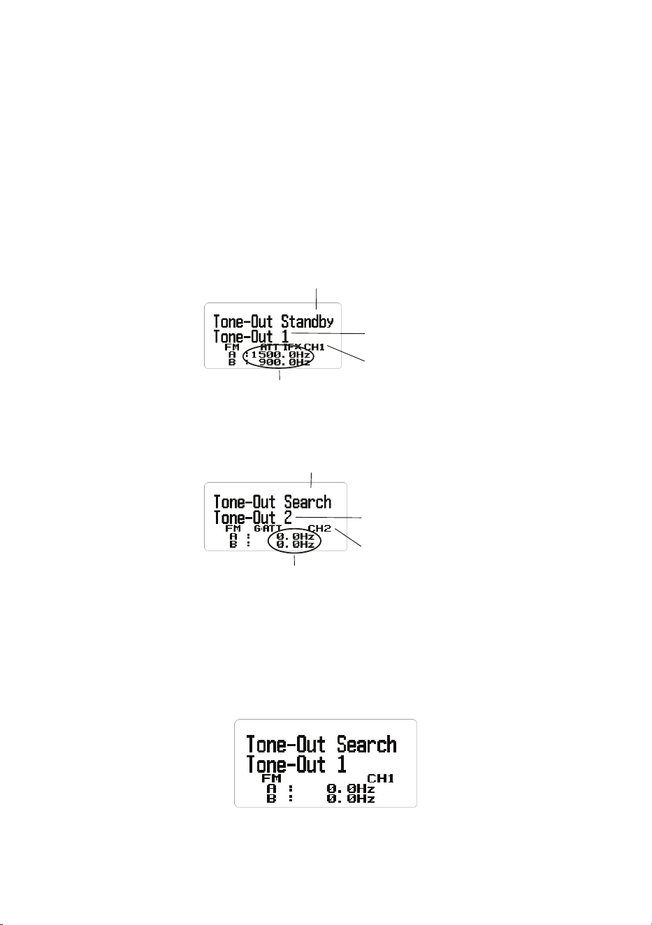
56
11. At Set Alert Level, scroll to Level 1 - Level 15 to hear volume levels or Auto
(the scanner sets the alert beep to the master volume level) and press E
Yes. Set Alert displays again.
12. Scroll to Set Alert Light and press E Yes. The Set Pattern menu displays.
13. Scroll to Off, On, Slow Blink, or Fast Blink and press E Yes. If a pattern is
selected (not Off), the Set Color screen displays.
14. Select a screen color (the screen changes to the color selected) and press
E Yes. The Set Alert screen displays again.
15. Press MENU twice and then repeat these steps to program more tones.
Tone-Out
channel number
Tone A and B frequencies
Tone-Out
channel name
Tone-Out Status =
Standby
Tone-Out
channel number
Tone A, B frequency = 0.0 Hz
Tone-Out
channel name
Tone-Out Status =
Search
USING TONE-OUT STANDBY/SEARCH
(See Setting Up Tone-Out rst, page 54.)
1. Press MENU. Scroll to Tone-Out for... and press E Yes.
2. Scroll to Tone-Out Standby and press E Yes. The Tone Out screen
displays.
NOTE: You can also assign Tone-Out to 1 of 3 Search (SRCH) keys.

57
3. The Tone-Out name, channel number (1-10), and tone settings display. Any
transmission received on that frequency will not be heard but you will still
see signal strength bars.
All Tone-Outs (channels) that have the same frequency (and modulation/
attenuation) as the one you select will also (and only) be monitored so you
can monitor up to 10 Tone-Out channels for one frequency. In this case, the
scanner displays each Tone-Out channel for two seconds. It does not scan
them; Tone-Out monitors the frequency for all Tone-Out channels with the
same frequency. Regardless of the current display, the scanner will alert
on any received Tone-Out that matches a stored setting (channel) for the
frequency.
If you press HOLD while in Standby/Search mode, the scanner temporarily
exits Tone-Out mode and you will be able to hear any transmissions on
that frequency. No alerts sound, even if a Tone-Out matches one you have
programmed in Hold mode. Press HOLD again to return to Standby/Search
mode.
IN TONE-OUT STANDBY MODE
• To select another Tone-Out, turn the Scroll knob.
• To save found tones in Tone-Out Search mode, press E Yes at Set Found
Tone A and B?
• To turn Intermediate Frequency Exchange on or off, push the FUNC knob,
then press 4 IFX.
• To turn attenuation on or off, push the FUNC knob, then press 7 ATT.
• To toggle modulation, push the FUNC knob, then press 9 MOD.
BAND SCOPE MODE
Band Scope mode searches a frequency range and displays the signal level
in real time. The screen displays the frequency increasing in value from left to
right, and a signal strength meter displays for signals. You can set the center
frequency and frequency range span. In Hold mode, you can monitor the
displayed frequency.
The scanner rapidly sweeps between the endpoints of the selected frequency
range and updates each bar segment with the relative signal strength in each
pass. Use the band scope in normal mode (the bars are all updated with the
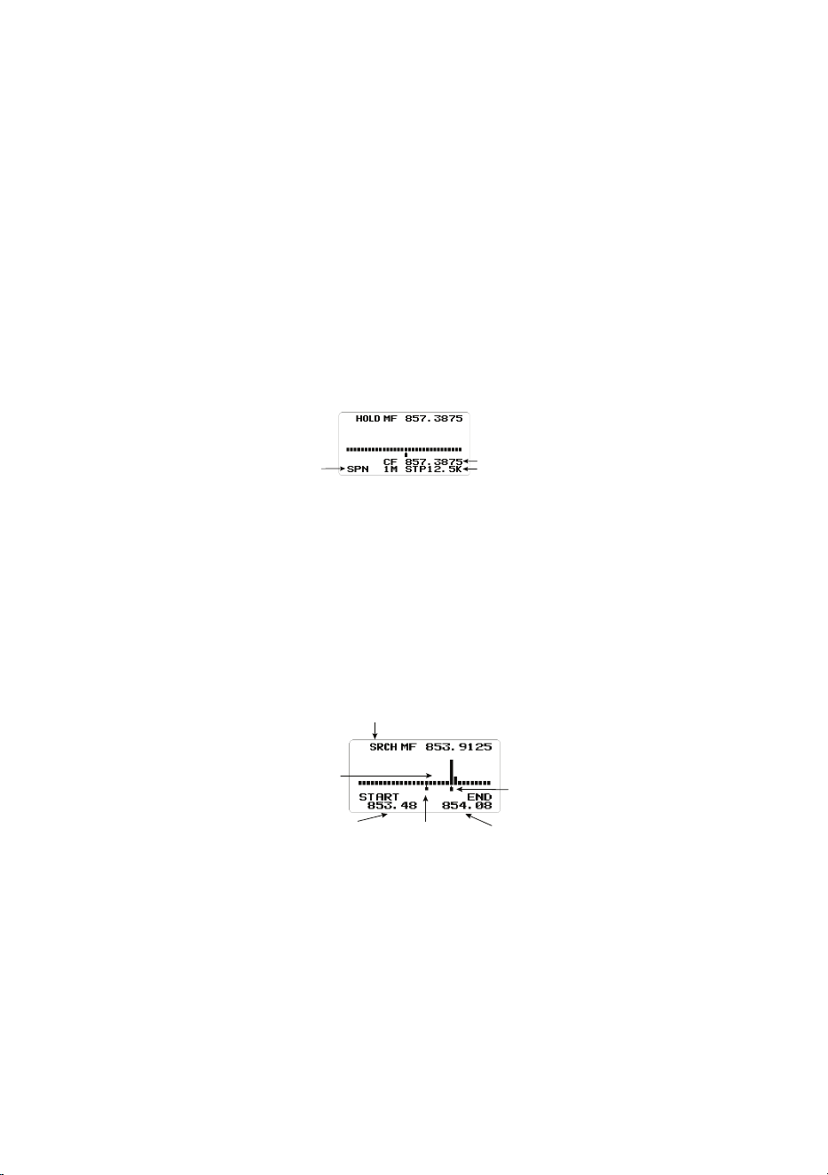
58
most recent signal strength) or Max Hold mode (the bars update only if there
is a stronger signal than one previously stored for the current position).
This feature allows you to get a “picture” of spectrum activity across the
selected range, identify intermittently active frequencies, check antenna
performance, check coax quality, and identify interference.
USING BAND SCOPE MODE
To start Band Scope mode, press HOLD on any channel or frequency and
then press the FUNC knob + 3 SRCH 3. This frequency becomes the center
frequency. Band Scope mode is assigned to this Search Key (3 SRCH) by
default.
Press . No to access the Search Span (SPN), Center Frequency (CF) and
Search Step (STP) elds in order. Press L/O to exit.
SPN (Search Span)
Hz
CF (Center Freq) MHz
STP (Search Step) Hz
NOTE: Band Scope mode can only be activated via the SRCH 3 key.
Band Scope has the following three modes:
• Search (SRCH)
• Max Hold Search Mode (MAX)
• HOLD (Hold)
Search Mode (SRCH)
Search Mode
Signal Strength
Bars
Frequency
Range Start
Frequency
Range End
Center
Frequency
Marker
Frequency
Marker
“SRCH” displays and the scanner searches and displays the frequency range
signals in real time. The frequency range is shown in bars determined by the
center frequency and span. While searching, the center frequency marker
(which shows the current frequency) blinks. The scanner starts from the lowest
frequency of the frequency range and searches to the highest frequency of
that range. If the scanner nds a transmission, it displays the most current
signal level in the bar for each frequency in the range.
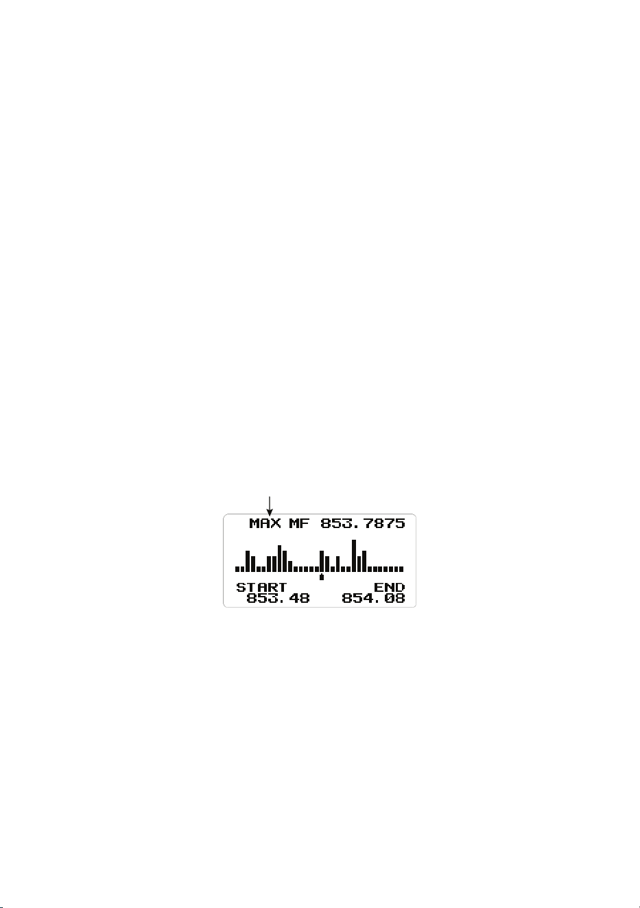
59
The center frequency marker ashes during Searching and Max Hold
Searching.
When you move the marker with the Scroll knob, the frequency of the signal
strength bar displays above the marker.
When you turn the Scroll knob, the marker usually moves according to the
preset step (STP). (See page 61 to change the search step.)
If the sweep range is set wide, a single bar will contain multiple frequency
ranges. This is why the marker moves slowly even when you turn the Scroll
knob. If you want to pinpoint the frequency, set the span range narrower. (See
page 61 to change the span range.)
NOTE: If you want to the listen to the signal at the marker position, see page
59.
NOTE: When scanning a band with a wide occupied frequency such as FM
broadcast, multiple bars appear due to the separation.
Press the FUNC knob then L/O to move the marker back to the center
frequency position. Doing this clears the history and restarts scanning from the
beginning.
Max Hold Search Mode (MAX)
If you want to switch to MAX Hold Search mode, press the FUNC knob +
SCAN/SEARCH to toggle between SRCH mode and MAX Hold Search mode.
MAX Mode
“Max” shows in the display and will freeze the signal strength bars at their
strongest signals.
To toggle between Search mode and Max Hold Search mode, press the FUNC
knob + SCAN/SEARCH.
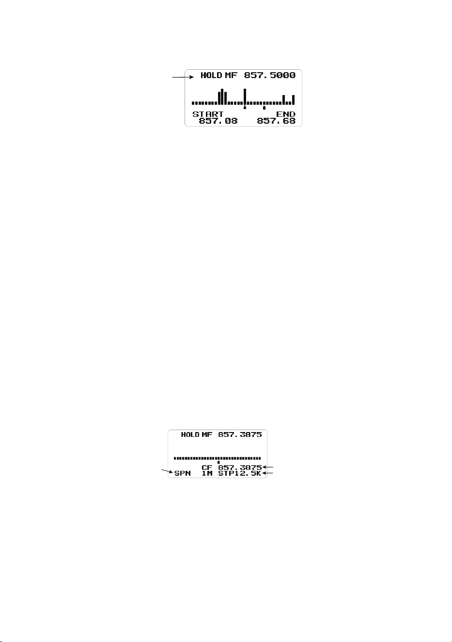
60
HOLD Mode (HOLD)
HOLD
Mode
“HOLD” displays and allows you hold the sweep then scroll to and listen to
that frequency. You can use the Scroll knob to move the frequency marker to
other locations, including the center frequency, and listen to that frequency.
To toggle between Hold mode and Search/Max Hold Search mode, press
HOLD.
Center frequency marker stops ashing in Hold mode.
NOTE: If the sweep range is set wide, a single signal bar will contain multiple
frequency ranges. This is why the marker moves slowly even when you turn
the Scroll knob.
If you want to pinpoint the frequency, set the span range narrower. (See page
61.)
NOTE: With MAX hold, the signal bar remains visible even with short duration
signals. Therefore, even if you move the marker to that frequency, you may
not be able to receive the signal because this is past information.
To return the marker to the center frequency position while in HOLD mode,
press the FUNC knob then L/O. Press HOLD to return to Search mode.
Change Center Frequency
SPN
(Search Span) Hz
CF (Center Freq) MHz
STP (Search Step) Hz
Enter a Specic Frequency
1. To change the center frequency, press . No until CF is blinking then press
E Yes. The Edit Center Freq menu displays.
2. Use the keypad to enter the new center frequency. Press E Yes to save
and exit.
NOTE: Setup mode automatically times out if there is no input for 10 seconds.
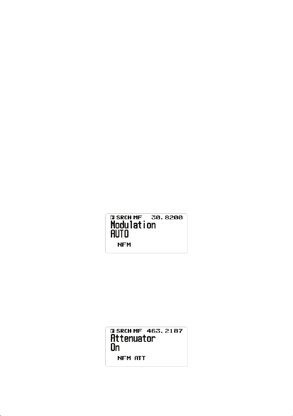
61
Set Current Frequency Marker Position to Center Frequency
1. Press . No until CF blinks.
2. To set the frequency at the frequency marker position as the center
frequency, press E Yes. The Edit Center Freq menu displays.
3. Use the keypad to enter the center frequency; press L/O to exit if there are
no additional settings.
Change the Search Span Range
1. To change the search span, press . No until SPN is blinking.
2. Turn the Scroll knob to select 0.2 - 500 MHz; press L/O to exit. Set a span
of 100, CF is at 50.
Change the Search Step
1. To change the search step, press . No until STP is blinking.
2. Turn the Scroll knob to change the search step options on the screen. Stop
at the desired search step.
3. Press L/O to exit.
Change Modulation
1. Press the FUNC knob + 9 MOD to access the modulation options. Keep
pressing 9 MOD quickly to cycle through the options. Normally, use the
default AUTO.
NOTE: When set to AUTO, a default modulation is automatically
selected for each frequency.
2. When you see the step setting you want, stop pressing 9 MOD.
Change Attenuation
1. Press the FUNC knob + 7 ATT to toggle the attenuator on or off. Keep
pressing 7 ATT quickly to cycle through On and Off.

62
NOTE: Press and hold 7 ATT to set global attenuation status. ATT
blinks when global attenuation is set.
2. When you see the setting you want, stop pressing 7 ATT.
NOTE: Press the FUNC knob to check the current modulation mode and
attenuator settings.
SETTINGS
SET BACKLIGHT
There are 5 different ways to use the backlight and 3 light intensities.
1. From MENU/Settings, select Set Backlight and press E Yes. The Set
Backlight menu displays.
2. Scroll to Set Dimmer and press E Yes to select it. The Set Dimmer screen
displays.
3. Select Auto (to set positive or negative polarity) or Manual (to set backlight
intensity to High, Middle, Low, or Off). Press E Yes to select it, and then
press MENU to return to the Settings menu.
See page 26 for detailed procedures.
SET RX LED
Set RX LED to On for the BLUE LED to turn on when receiving a signal.
See page 27 for detailed procedures.
ADJUST KEY BEEP
This setting turns key beep on and off and adjusts its volume level.
1. From MENU/Settings, scroll to Adjust Key Beep and press E Yes. The
Adjust Key Beep screen displays.
2. Key beep options are Auto (the scanner sets the alert beep to the master
volume level), Level 1 - Level 15 (the scanner sounds the level as you
scroll through the levels), and Off. Scroll to a selection and press E Yes to
select it and return to the Settings menu.
See page 27 for detailed procedures.

63
SET UPSIDE-DOWN
This setting controls the display orientation. When On is selected, the
BCD260DN inverts the display’s text and graphics. This allows the unit to be
installed in an unconventional manner with the screen displaying normally.
See page 27 for detailed procedures.
ADJUST CONTRAST
This setting controls the display’s contrast.
See page 27 for detailed procedures.
BAND DEFAULTS
This setting allows you to change the “Auto” (default) values to whatever you
feel “Auto” should be for each band (vs. the radio defaults). Since all of the
step and modulation settings default to “Auto,” this allows you to skip those
settings when programming.
NOTE: These settings do not affect service searches.
See page 28 for detailed procedures.
FACTORY RESET
WARNING: Resetting the scanner clears all data and settings you have
entered. You cannot restore user programmed data that has been
deleted. You can restore only the original factory settings.
1. From MENU/Settings, scroll to Factory Reset and press E Yes. Cancel and
OK display.
2. Select OK to reset the scanner to factory settings or Cancel to return to the
Settings menu. Press E Yes.
3. If you reset the scanner to factory settings, the power will turn off after the
data is erased and restored to factory settings.
NOTE: To save the settings, Uniden recommends using the BCDX60DN SS
program to back them up before resetting. Refer to www.uniden.com for BC_
VUP software.
FIRMWARE VERSION
This menu allows you view the rmware version, the serial number, and the
checksum. Uniden recommends that you download and install the latest
rmware upgrade for the scanner if you don’t already have it.
1. From MENU/Settings, scroll to Firmware Version and press E Yes.
2. The rmware version, serial number, and checksum display.
3. Press MENU to return to the Settings menu.

64
OTHER OPERATIONS
VIEWING THE DIGITAL DECODER ERROR RATE
1. To view the digital decoder error rate, push the FUNC knob + VOL knob.
NOTE: A smaller ERR: number means fewer errors. This mode never
times out.
2. Press the FUNC knob + VOL knob to exit this mode.
UPDATE FIRMWARE USING PC
From time to time, Uniden will release rmware updates to improve existing
functionality, add new features, or address issues found in its operation.
Updating the rmware takes just a few minutes and is easily accomplished
using Sentinel software.
BC_VUP software is available for download through the BCD260DN’s product
page at www.uniden.com, Customer Support. BC_VUP connects to the
internet and checks for the current rmware version to download.
After downloading the BC_VUP software to your PC, simply connect your
scanner to your PC using the supplied USB cable. Then, in BC_VUP, select
Model/Version and follow the on-screen prompts.
HOW DO I . . . ?
How Do I . . . ? Set Up Do This
Assign channels Go to: MENU/Program
Channel.
Select the bank you want to
use for the custom service and
name it.
Select Edit Channel. The next
menu selections let you assign
a frequency to a channel in the
selected bank and adjust that
channel’s settings. See page
72 for details.
Start scanning Press SCAN/SEARCH.
Pause and restart
scanning
Press HOLD to pause
scanning. Press HOLD again to
resume scanning.

65
How Do I . . . ? Set Up Do This
Scan a different
bank than the
current bank.
Be in Scan mode. Press 0 - 9 to turn off the banks
you do NOT want to scan. The
scanner will scan the active
banks.
Scan Weather
Channels
Press MENU/WX Operation/
Weather Scan.
Create a Quick
Search
Be in Scan mode or
Tone-Out mode.
Press the FUNC knob and
SCAN/SEARCH key. The
scanner begins scanning all
frequencies.
Create a Custom
Search
Go to MENU/Search For.../
Edit Custom. Select a custom
Search (1 - 10) and enter the
lower and upper limits.
Search Service
Channels
Go to: MENU/Search For.../
Service Search.
Scroll through the service
types and select one to search.
These service frequencies are
preloaded into the BCD260DN.
Create a Custom
Service Search
Search the internet
for specific service
frequencies you
want.
Go to: MENU/Program
Channel.
Select a bank to program your
specific search frequencies
into. Edit the name to
something that is appropriate to
the service frequencies you are
entering.
Next, select Edit Channel.
Scroll to an empty channel
and enter the service search
frequency there.
Set a channel as a
Priority Channel
Hold on a channel/
frequency.
Go to MENU/Priority Scan/Set
Priority.

66
APPENDIX A
BAND DEFAULTS
Frequency
Range
Step
(kHz)
Mode Band Frequency
Range
Step
(kHz)
Mode Band
25.000-
26.9600
5 AM Petroleum 174.0000-
215.9500
50 WFM VHF TV
26.9650-
27.4050
5 AM CB Class D
Channel
216.0000-
224.9800
20 NFM 1.25 Meter Ham
27.4100-
27.9950
5 AM Business/Forest 225.0000-
379.9750
25 AM UHF Air
28.000-
29.6800
20 NFM 10 Meter Ham 380.0000-
399.9875
12.5 NFM Military
29.7000-
49.9900
10 NFM VHF Low 400.0000-
405.9875
12.5 NFM Miscellaneous
50.000-
53.9800
20 NFM 6 Meter Ham 406.0000-
419.9875
12.5 NFM Federal
54.0000-
71.9500
50 WFM VHF TV 420.0000-
449.9875
12.5 NFM 70 cm Ham
72.0000-
75.9950
5 FM Astronomy 450.0000-
469.9875
6.25 NFM UHF Standard
76.0000-
87.9500
50 WFM VHF TV 470.0000-
512.0000
12.5 NFM UHF TV
88.0000-
107.9000
100 FMB FM Broadcast 758.0000-
775.99375
6.25 NFM Public Service
108.0000-
136.9916
8.33 AM Commercial Air 793.0000-
805.99375
6.25 NFM Public Service
137.000-
143.9875
12.5 NFM Military Land
Mobile
806.0000-
823.9875
12.5 NFM Public Service
144.0000-
147.9950
5 NFM 2 Meter Ham 849.0125-
868.9875
12.5 NFM Public Service
148.0000-
150.7875
12.5 NFM Military Land
Mobile
894.0125-
960.0000
12.5 NFM Public Service
150.8000-
161.9950
5 NFM VHF High 1240.0000-
1300.0000
12.5 NFM 23 cm Amateur
Band
162.0000-
173.9875
12.5 NFM Federal

67
Frequency
Range
Step
(kHz)
Mode Band Frequency
Range
Step
(kHz)
Mode Band
NOTE: When you select AUTO for a channel or mode’s modulation or
step, these values are used UNLESS you have edited the Band Defaults.
Although television bands are listed, the scanner does not decode digital TV
audio.
WEATHER CHANNELS
Channel Frequency Channel Frequency
1 162.5500 5 162.4500
2 162.4000 6 162.5000
3 162.4750 7 162.5250
4 162.4250
SAME EVENT CODES
Standard Event Code Warning
Watch Advisory
Description
ADR Administrative
Message
O
Admin Message
AVA Avalanche Watch O Avalanche
AVW Avalanche Warning O Avalanche
BHW Biological Hazard
Warning
O
Biological
BWW Boil Water Warning O Boil Water
BZW Blizzard Warning O Blizzard
CAE Child Abduction
Emergency
O
Child
Emergency
CDW Civil Danger Warning O Civil Danger
CEM Civil Emergency
Message
O
Civil EMG
CFA Coastal Flood Watch O Coastal Flood
CFW Coastal Flood
Warning
O
Coastal Flood
CHW Chemical Hazard
Warning
O
Chemical
CWW Contaminated Water
Warning
O
Contam. Water
DBA Dam Watch O Dam Break
DBW Dam Break Warning O Dam Break

68
Standard Event Code Warning
Watch Advisory
Description
DEW Contagious Disease
Warning
O
Contagious
DMO Practice/Demo O System Demo
DSW Dust Storm Warning O Dust Storm
EAN Emergency Action
Notification
O
EMG Notify
EAT Emergency Action
Termination
O
EMG Terminate
EQW Earthquake Warning O Earthquake
EVA Evacuation Watch O Evacuate Note
EVI Immediate Evacuation O Evacuate Note
EWW Extreme Wind
Warning
O
Extreme Wind
FCW Food Contamination
Warning
O
Food
FFA Flash Flood Watch O Flash Flood
FFS Flash Flood
Statement
O
Flash Flood
FFW Flash Flood Warning O Flash Flood
FLA Flood Watch O Flood
FLS Flood Statement O Flood
FLW Flood Warning O Flood
FRW Fire Warning O Fire
FSW Flash Freeze Warning O Flash Freeze
FZW Freeze Warning O Freeze
HLS Hurricane Statement O Hurricane
HMW Hazardous Material
Warning
O
Hazardous
HUA Hurricane Watch O Hurricane
HUW Hurricane Warning O Hurricane
HWA High Wind Watch O High Wind
HWW High Wind Warning O High Wind
IBW Iceberg Warning O Iceberg
IFW Industrial Fire
Warning
O
Industrial Fire

69
Standard Event Code Warning
Watch Advisory
Description
LAE Local Area
Emergency
O
Local EMG
LEW Law Enforcement
Warning
O
Law Enforce.
LSW Land Slide Warning O Land Slide
NAT National Audible Test O National Audible
NIC National Information
Center
O
National Info
NMN Network Notification
Message
O
Network
Message
NPT National Periodic Test O Nation Period
NST National Silent Test O Nation Silent
NUW Nuclear Power Plant
Warning
O
Nuclear Plant
POS Power Outage
Advisory
O
Power Outage
RHW Radiological Hazard
Warning
O
Radiological
RMT Required Monthly
Test
O
Monthly
RWT Required Weekly Test O Weekly
SMW Special Marine
Warning
O
Special Marine
SPS Special Weather
Statement
O
Special WX
SPW Shelter In-Place
Warning
O
Shelter
SSA Storm Surge Watch O Storm Surge
SSW Storm Surge Warning O Storm Surge
SVA Severe Thunderstorm
Watch
O
Thunderstorm
SVR Severe Thunderstorm
Warning
O
Thunderstorm
SVS Severe Weather
Statement
O
Severe WX

70
Standard Event Code Warning
Watch Advisory
Description
TOA Tornado Watch O Tornado
TOE 911 Telephone
Outage Emergency
O
911 Phone
Outage
TOR Tornado Warning O Tornado
TRA Tropical Strom Watch O Tropical Storm
TRW Tropical Storm
Warning
O
Tropical Storm
TSA Tsunami Watch O Tsunami
TSW Tsunami Warning O Tsunami
TXB Transmitter Backup
On
O
TX Backup On
TXF Transmitter Carrier
Off
O
TX Carrier Off
TXO Transmitter Carrier
On
O
TX Carrier On
TXP Transmitter Primary
On
O
TX Primary On
VOW Volcano Warning O Volcano
WFA Wild Fire Watch O Wild Fire
WFW Wild Fire Warning O Wild Fire
WSA Winter Storm Watch O Winter Storm
WSW Winter Storm Warning O Winter Storm
**A Unrecognized Watch O Unrecognized
**E Unrecognized
Emergency
O
Unrecognized
**S Unrecognized
Statement
O
Unrecognized
**W Unrecognized
Warning
O
Unrecognized
Continuous Tone Coded Squelch System (CTCSS) and Digital Coded
Squelch (DCS) are two methods used to prevent interference by other radio
communications. Your scanner can receive transmissions that use these
codes.
CTCSS and DCS systems all use some form of coded squelch. Coded
squelch involves the transmission of a special code signal along with the audio

71
of a radio transmission. A receiver with coded squelch only activates when
the received signal has the correct code. This lets many users share a single
frequency, and decreases interference caused by distant transmitters on the
same channel. In all major metropolitan areas of the United States, every
available radio channel is assigned to more than one user.
CTCSS TONES
The scanner can detect the following 50 CTCSS tones.
67.0Hz 94.8Hz 131.8Hz 171.3Hz 203.5Hz
69.3Hz 97.4Hz 136.5Hz 173.8Hz 206.5Hz
71.9Hz 100.0Hz 141.3Hz 177.3Hz 210.7Hz
74.4Hz 103.5Hz 146.2Hz 179.9Hz 218.1Hz
77.0Hz 107.2Hz 151.4Hz 183.5Hz 225.7Hz
79.7Hz 110.9Hz 156.7Hz 186.2Hz 229.1Hz
82.5Hz 114.8Hz 159.8Hz 189.9Hz 233.6Hz
85.4Hz 118.8Hz 162.2Hz 192.8Hz 241.8Hz
88.5Hz 123.0Hz 165.5Hz 196.6Hz 250.3Hz
91.5Hz 127.3Hz 167.9Hz 199.5Hz 254.1Hz
DCS CODES
The scanner can detect the following 112 hexadecimal DCS codes.
006 007 015 017 021 023 025 026
031 032 036 043 047 050 051 053
054 065 071 072 073 074 114 115
116 122 125 131 132 134 141 143
145 152 155 156 162 165 172 174
205 212 214 223 225 226 243 244
245 246 251 252 255 261 263 265
266 271 274 306 311 315 325 331
332 343 346 351 356 364 365 371
411 412 413 423 431 432 445 446
452 454 455 462 464 465 466 503
506 516 523 526 532 546 565 606
612 624 627 631 632 654 662 664
703 712 723 731 732 734 743 754

72
APPENDIX B - MENU STRUCTURE
PROGRAM CHANNEL MENU
The Program Channel menu series allows you to set up channel banks,
assign frequencies to channels, and set channel characteristics.
From MENU/Program Channel/Select Bank
Select Bank
(Bank 1 -
Bank 10)
Edit Name Text entry
screen
Edit Channel,
then Select
Channel
Edit Name Text entry
screen
Edit
Frequency
Frequency
entry screen
Set Audio
Type
All
Digital Only Search
Set Color Code
Set NEXEDGE
RAN
Set IDAS Area
Analog Only Search
CTCSS
DCS
Set Lockout
Set
Modulation
Auto
AM
NFM
FM
WFM
FMB

73
From MENU/Program Channel/Select Bank
Edit Channel,
then Select
Channel
(Cont.)
Set Delay
Time
-10, -5, -2, 0,
1, 2, 5, 10,
30 seconds
Set
Attenuator
On, Off
Set Priority On, Off
Set Alert Set Alert
Tone:
Off
Alert 1 - 9
Set Alert Level:
Auto
Level 1 - 15
Set Alert
Light:
Off
On
Slow Blink
Fast Blink
NOTE: If On is
selected, the
Set Color menu
displays. See
page 10 for a
complete list of
color options.
Set Record On
Off
Set Lockout Unlocked
Temporary
L/O
Lockout
Volume
Offset
-3, -2, -1, 0,
1, 2, 3
Digital
Waiting
In ms:
1, 100, 200 -
1000
Clear
Channel
Confirm
Copy Bank Confirm
Copy Bank
Clear Bank Confirm
Clear Bank

74
SEARCH OPTIONS MENU
Search Options let you set up 3 searchable options:
• Freq Lockouts
• Broadcast Screen
• Tone/Code Search
From MENU/Search Options
Freq
Lockouts
Unlock All
Rvw Search
L/O
Broadcast
Screen
Set All Band
On
On
Set All Band
Off
Off
Set Each Band Pager
FM
UHF TV
VHF TV
NOAH WX
Band 1 - 10
Program Band Band 1 - 10 Set Upper Limit
Set Lower Limit
Tone/Code
Search
Off
CTCSS
Color/Ran/Area
SEARCH FOR... MENU
This menu lets you establish characteristics for different searches.
• Service Search
• Set Service List
• Edit Service
• Custom Search
• Edit Custom
• Quick Search
• Set Quick Search
• Set SR1-3 Keys

75
From MENU/Search For. . .
Service Search Public Safety
Media
Ham Radio
Railroad
Air Band
CB Radio
FRM/GMRD/MURS
Racing
FM Broadcast
Military Air
Custom 1 - 3
Set Service List Public Safety
Media
Ham Radio
Railroad
Air Band
CB Radio
FRM/GMRD/MURS
Racing
FM Broadcast
Military Air
Custom 1 - 3
NOTE: Each option allows you
to edit the name and to select
an option/bank from that service
category.
Edit Service Delay Time
Attenuator
Record
Digital Waiting
Custom Search Searches established
custom searches
Edit Custom Select a custom
list and select
characteristics to edit/
set.

76
From MENU/Search For. . .
Quick Search Enter Start Freqnency
Enter End Frequency
Set Quick
Search
Set Delay Time
Set Attenuator
Digital Waiting
Set SR1 - 3
Keys
Select an SR key Set
charactistic
to edit/set.
Not Assign
Custom
Search
Weather
Channel
Tone Out
Band
Scope
Public
Safety
Ham Radio
:
Custom
1 - 3
PRIORITY SCAN MENU
Priority Scan checks the priority channels every 2 seconds during normal
scanning. The scanner can scan up to 100 priority channels. If there are more
than 100 priority channels, only the rst 100 will be scanned. If there are
no priority channels or all priority channels are locked out, Priority Scan No
Channel displays.
From MENU/Priority Scan
Set Priority Off
On
Plus On
DND (Do Not Disturb)
Set Interval 1 - 10 seconds
MaxCHs/Pri-Scan 1 - 100 channels

77
WX OPERATION MENU
See page 49 for details about weather operation.
WX Operation establishes weather scanning settings.
• Weather Scan
• Weather Alert
• Program SAME
• Set Delay Time
• Set Attenuator
• Set Record
• WX Alt Priority
From MENU/WX Operation
Weather Scan (A WX scan begins)
Weather Alert Alert Only
Same 1 - 5
All FIPS
Program SAME Alert Only
SAME 1 - 5 Edit
Name
Edit
County
Select Code No. 1 - 8
Edit FIPS Code
Set Delay Time -10
-5
-2
0
1
2
5
10
Set Record On
Off
Set Attenuator On
Off
WX Alt Priority On
Off

78
TONE-OUT FOR... MENU
See page 56 for details about Tone-Out operations.
Tone-Out refers to an emergency signal indicating that the emergency
requires more personnel than are on duty. This menu sets parameters for the
actual physical tone-out tone.
• Tone-out Standby
• Tone-Out Setup
From MENU/Tone Out For. . .
Tone-Out
Standby
Go to Tone-
Out mode
Tone-Out
Setup
Tone-Out
1- 10
Edit
Name
Set
Frequency
Edit
Frequency
Edit
Modulation
Set
Attenuator
Set Tone Edit Tone
A
Edit Tone
B
Set
Delay
Time
0, 1, 2, 5,
10, 30 sec
Infinity
Set Alert Set Alert
Tone
Tone: Off, Alert
1 - 9
Level: Auto,
1 - 15
Set Alert
Light
Off
On (See page
79 for a list of
color options.)
Slow Bink
Fast Blink
Set
Record
On
Off

79
SETTINGS MENU
The Settings menu establishes certain physical items regarding the scanner:
• Set Backlight
• Set RX LED
• Adjust Key Beep
• Set Upside-down
• Adjusting Contrast
• Band Defaults
• Factory Reset
• Firmware Version
From MENU/Settings
Set Backlight Set Dimmer Auto (If Auto selected, Set
Polarity menu displays to set
positive or negative polarity.)
Manual - (If Manual selected,
Select Dimmer menu
displays to set the dimmer
brightness level to High,
Middle, Low, or Off.)
Set Color Select one of the following
colors for the screen
backlight:
• Cyan
• Yellow
• White
• Blue
• Red
• Magenta
• Green
Set RX LED On
Off
• If ON is selected, the RX
LED light turns blue when
transmissions are received.
Adjust Key
Beep
Auto
Level 1 - 15
Off
Set Upside-
down
On
Off

80
From MENU/Settings
Adjust
Contrast
Contrast 1 - 15
Band Defaults Select a band from
list of bands and
their defaults. Next,
set modulation:
AM
NFM
FM
VFM
FMB
Set Step
Factory Reset Cancel
OK
Firmware
Version
Displays firmware
version, SN, and
CHECKSUM.

81
TECHNICAL SPECIFICATIONS
Band Coverage: 31 Bands
Certied in accordance with FCC Rules and Regulations Part 15 Sub-part C
as of date of manufacture
Antenna Impedence: 50 Ω
Power Requirements: DC 11.0V ~ 16.6V (Ext. DC Power Jack or DC Power
Jack)
Size (without antenna, knob, brackets, and other projections):
7.24 in (W) x 5.94 in (D) x 2.2 in (H) (without antenna, knob, brackets,
and other projections)
184 mm (W) x 151 mm (D) x 56 mm (H) (without antenna, knob,
brackets, and other projections)
Weight: 3.2 lbs. (1.5 kg.) (Without antenna and brackets)
Operating Temperature: Nominal: – 4º F (– 20º C) to + 140º F (+ 60º C)
Storage Temperature: – 22º F (– 30º C) to + 158º F (+ 70º C )
LCD Display: 64 x 128 Full Dot Matrix LCD
LED Indications: RX LED: Blue
Alert LED: Red
Internal Speaker: 8 Ω, 5 W Max. 77mm Ø
Weather Channels: 7 Channels
External Jacks: Antenna Jack: BNC Type
Headphone Jack: 3.5mm Ø (Stereo Type*)
Ext. SP Jack: 3.5mm Ø (Monaural Type)
REC Out Jack: 3.5mm Ø (Stereo Type*)
DC Power Jack: 5.5mm Ø (Center Positive)
*NOTE: Audio does not play in stereo.
USB Jack: 5-pin mini Type B
External DC Power/ORG Wire Jack: 3-Pin (Center Orange Wire)
Sensitivity (12dB SINAD)
VHF Low Band 1
(AM) 25.005 MHz 0.49 μV
(NFM) 40.840 MHz 0.36 μV
(NFM) 53.980 MHz 0.33 μV

82
VHF Low Band 2
(WFM) 54.050 MHz 0.73 μV
(FM) 72.515 MHz 0.26 μV
(FMB) 107.500 MHz 0.53 μV
Aircraft Band
(AM) 118.800 MHz 0.35 μV
(AM) 127.175 MHz 0.36 μV
(AM) 135.500 MHz 0.36 μV
VHF High Band 1
(NFM) 138.150 MHz 0.32 μV
(NFM) 161.985 MHz 0.35 μV
(NFM) 173.225 MHz 0.36 μV
(WFM) 197.450 MHz 0.66 uV
(NFM) 216.020 MHz 0.29 uV
VHF High Band 2
(AM) 225.050 MHz 0.36 μV
(AM) 272.950 MHz 0.37 μV
(AM) 315.050 MHz 0.37 μV
UHF Band
(AM) 325.050 MHz 0.35 μV
(NFM) 406.875 MHz 0.28 μV
(NFM) 511.9125 MHz 0.29 μV
Public Service Band
(NFM) 758.0125 MHz 0.33 μV
(NFM) 806.000 MHz 0.34 μV
(NFM) 857.150 MHz 0.31 μV
(NFM) 954.9125 MHz 0.30 μV
1200MHz Band
(NFM) 1299.925 MHz 0.48 μV
Hum & Noise
VHF Low Band 1
(AM) 25.005 MHz 43 dB
(NFM) 40.840 MHz 44 dB

83
VHF Low Band 2
(WFM) 54.050 MHz 53 dB
(FM) 72.515 MHz 50 dB
(FMB) 107.500 MHz 60 dB
Aircraft Band
(AM) 127.175 MHz 43 dB
VHF High Band 1
(NFM) 161.985 MHz 43 dB
(NFM) 173.225 MHz 44 dB
(WFM) 197.450 MHz 53 dB
VHF High Band 2
(AM) 272.950 MHz 44 dB
UHF Band
(AM) 325.050 MHz 45 dB
(NFM) 406.875 MHz 44 dB
Public Service Band
(NFM) 758.0125 MHz 44 dB
(NFM) 857.150 MHz 44 dB
1200 MHz Band
(NFM) 1299.925 MHz 43 dB
Audio Output Power:
At 8Ω speaker Jack
2.6W @ FM, FMB and NFM bands
2.7W @ AM bands
2.5W @ WFM bands
At 32Ω stereo headphone Jack
6mW @FM, NFM Bands
7mW @FMB, WFM Bands
10mW @AM Bands
Power Consumption @ 13.8VDC:
SQ Closed / Backlight White / High: 230mA
Full Audio Output / Backlight Off: 410mA
Ful Audio Output / Backlight White: 540mA

84
REC output voltage @ 600Ω Load (FM): 230mV
Orange Wire Operation: DC 3V ~ 16.6V (Less than 10mA)
Band Scope Function: Frequency Span: 0.2 ~ 500MHz
Frequency Step: 5 ~ 100kHz
NOTE: All data is Nominal.
Features, specications, and availability of optional accessories are all subject
to change without notice.
Warranty Information
WARRANTOR: UNIDEN AMERICA CORPORATION (Uniden)
ELEMENTS OF WARRANTY: Uniden warrants, for one year, to the original
retail owner, this Uniden Product to be free from defects in materials and
craftsmanship with only the limitations or exclusions set out below.
WARRANTY DURATION: This warranty to the original user shall terminate
and be of no further effect 12 months after the date of original retail sale.
The warranty is invalid if the Product is
(A) damaged or not maintained as reasonable or necessary,
(B) modied, altered, or used as part of any conversion kits, subassemblies, or
any congurations not sold by Uniden,
(C) improperly installed,
(D) serviced or repaired by someone other than an authorized Uniden service
center for a defect or malfunction covered by this warranty,
(E) used in any conjunction with equipment or parts or as part of any system
not manufactured by Uniden, or
(F) installed or programmed by anyone other than as detailed by the Operating
Guide for this product.
STATEMENT OF REMEDY: In the event that the product does not conform
to this warranty at any time while this warranty is in effect, warrantor will
repair the defect and return it to you without charge for parts, service, or
any other cost (except shipping and handling) incurred by warrantor or its
representatives in connection with the performance of this warranty. THE
LIMITED WARRANTY SET FORTH ABOVE IS THE SOLE AND ENTIRE
WARRANTY PERTAINING TO THE PRODUCT AND IS IN LIEU OF AND
EXCLUDES ALL OTHER WARRANTIES OF ANY NATURE WHATSOEVER,
WHETHER EXPRESS, IMPLIED OR ARISING BY OPERATION OF LAW,
INCLUDING, BUT NOT LIMITED TO ANY IMPLIED WARRANTIES OF
MERCHANTABILITY OR FITNESS FOR A PARTICULAR PURPOSE.
THIS WARRANTY DOES NOT COVER OR PROVIDE FOR THE

85
REIMBURSEMENT OR PAYMENT OF INCIDENTAL OR CONSEQUENTIAL
DAMAGES. Some states do not allow this exclusion or limitation of incidental
or consequential damages so the above limitation or exclusion might not apply
to you.
LEGAL REMEDIES: This warranty gives you specic legal rights, and you
might also have other rights which vary from state to state.
This warranty is void outside the United States of America.
PROCEDURE FOR OBTAINING PERFORMANCE OF WARRANTY: If,
after following the instructions in this Operating Guide you are certain that
the Product is defective, pack the Product carefully (preferably in its original
packaging). Include evidence of original purchase and a note describing the
defect that has caused you to return it. The Product should be shipped freight
prepaid, by traceable means, or delivered, to warrantor at:
Uniden America Corporation
301 International Parkway, Suite 460
Flower Mound, Texas 75022