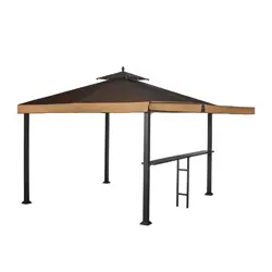
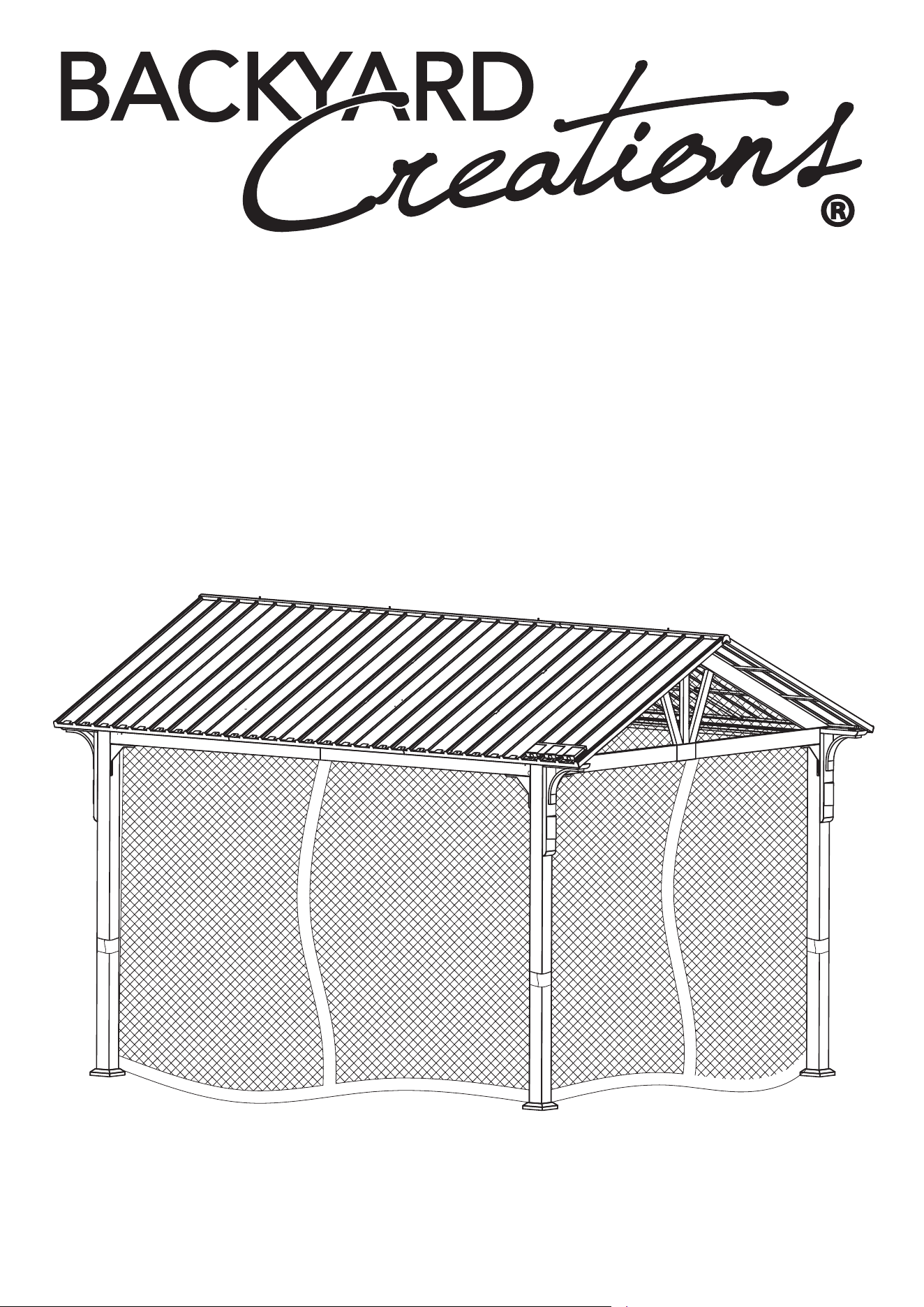
VESTAVIA 10’×12’ GABLE GAZEBO WITH SOLAR
LED LIGHTS AND NETTING
Style# GFS60014J-M1/GFS60014J-M2
Sku # 272-3020/272-3021
>>assembly instructions

Warranty
1 YEAR LIMITED FRAME WARRANTY.
WHAT IS COVERED
We warrant the frames to be free of manufacturing defects to the original
purchaser for one year, and a one year limited warranty for the fabric.
WHAT IS NOT COVERED
It remains the customer’s responsibility for freight and packaging charges
to and from our service center. This warranty does not cover commercial
use, hardware, acts of nature, fire, freezing and abusive use. In addition,
purchased parts are not covered under this warranty. We reserve the right
to make substitutions with similar merchandise, if the model in question is
no longer in production.
WARNING
For your own safety, and to reduce the risk of serious personal injury,
the user must read and understand this Use and Care Guide, and assemble
each piece only in accordance with these instructions and with the parts
and hardware included with the original packaging.
Failure to follow these instructions and/or use of tools or hardware not
included in the original packaging may lead to improper assembly
and/or risk of serious personal injury.
WARNING
KEEP PLASTIC BAGS AND SMALL PARTS AWAY FROM CHILDREN.
DO NOT USE POWER TOOLS.DO NOT OVERTIGHTEN HARDWARE.
PERIODICALLY CHECK HARDWARE AND RE-TIGHTEN
AS NECESSARY. DO NOT USE PRODUCT IF ANY COMPONENT
BECOMES DAMAGED. FOR RESIDENTIAL (NON-COMMERCIAL)
USE ONLY.DO NOT STAND ON PRODUCT. USE ONLY FOR
INTENDED PURPOS.
2

CARE AND CLEANING
FRAME: WIPE CLEAN WITH A MILD SOAP AND WATER SOLUTION,
RINSE WITH CLEAN WATER, AND DRY THOROUGHLY.
IMPORTANT
ASSEMBLE ON A STABLE LEVEL SURFACE TO AVOID DAMAGE TO
GAZEBO AND POSSIBLE INJURY.
TWO PEOPLE ARE REQUIRED TO ASSEMBLE THIS PRODUCT. INSTALL
ALL BOLTS BY HAND LOOSELY THREADED BEFORE FULLY
TIGHTENING ANY BOLTS. ONCE ALL BOLTS ARE INSTALLED LOOSELY,
THEN SECURE THE BOLTS BEFORE MOVING ON TO NEXT STEP.
IF YOU HAVE ANY QUESTIONS OR CONCERNS PLEASE CALL US TOLL
FREE AT 1-866-905-4107
MONDAY-FRIDAY 8:30 AM TO 5:00 PM PACIFIC TIME / 11:30 AM TO 8:00
PM EASTERN TIME.
3

TABLE OF CONTENTS
Introduction
Hardware
Parts List
Assembly
2-3
5-8
9
11-60
Tool Required 10
4
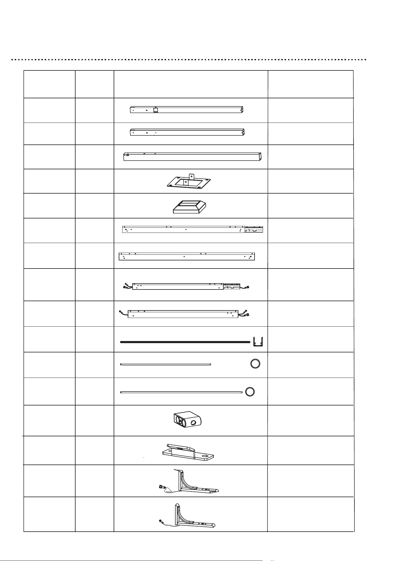
PARTS LIST
1
A1
A2
A3
B
C
D1
D2
D3
D4
E
F
F1
F2
G
H1
H2
Part QTY PIECE DESCRIPTION
1
2
4
4
2
2
2
2
4
8
8
16
6
2
2
Post leg
Post leg
Post leg
Foot plate
Foot plate cover
Long beam
Long beam
Short beam
Short beam
Light strip tube
Short fiberglass rod
Long fiberglass rod
plastic
Middle inclined beam
connector
Corner connector
Corner connector
5
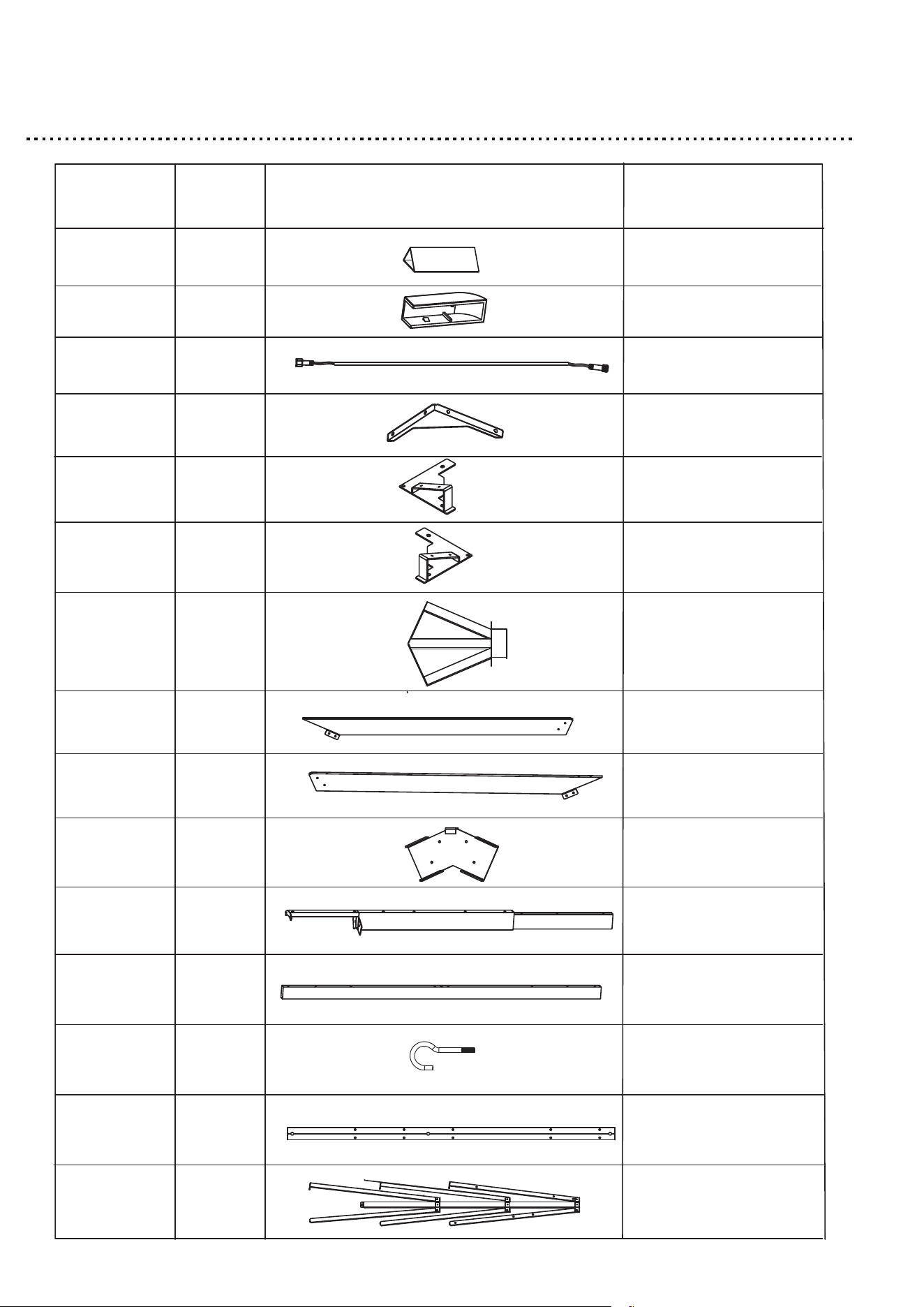
PARTS LIST
4
H3
I1
I2
J
K1
K2
L1
L2
L3
L4
M1
M2
N
O
Part QTY PIECE DESCRIPTION
4
2
10
2
2
2
2
2
2
2
1
1
4
Down light
Light bar plastic part
Light bar
Gable support
Top of post leg plate
Top of post leg plate
Gable
Inclined beam
Inclined beam
Inclined beam
connector
Top beam
Hook
Roof connector
P1
2
Top beam
Rafter branch unit
6
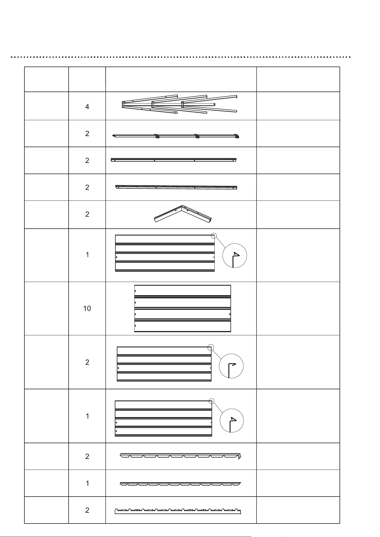
PARTS LIST
P2
P3
Q1
Q2
Q3
R1
R2
R3
R4
S1
S2
Part QTY
T1
PIECE DESCRIPTION
Rafter branch unit
Rafter branch unit
Cross beam
Cross beam
Cross beam
connector
Roof panel
Roof panel
Roof panel
Roof panel
Roof top cover
Roof top cover
Roof edge cap
7
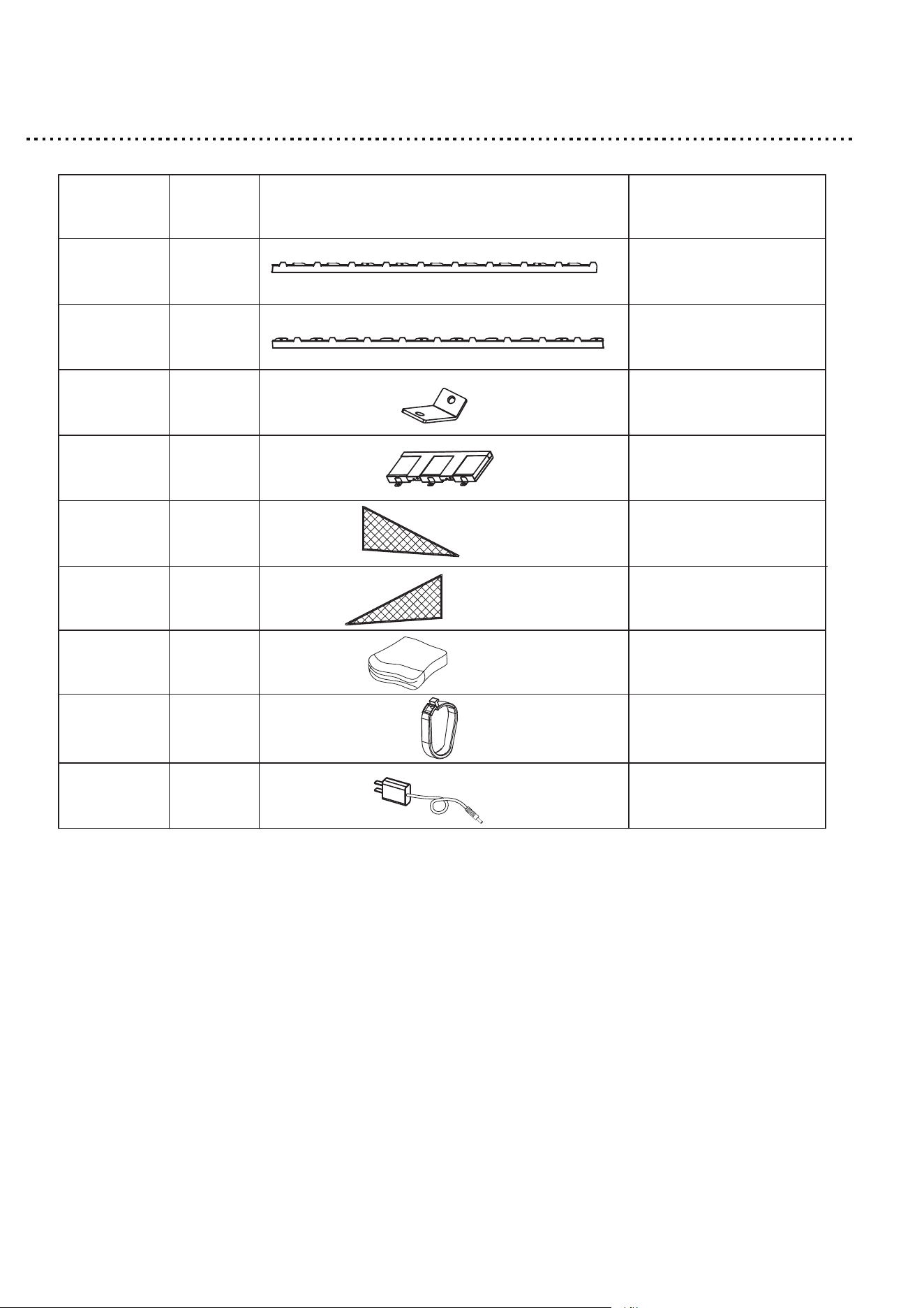
PARTS LIST
Part QTY
PIECE
DESCRIPTION
T2
T3
U
V
Y1
Y2
Y3
Y4
Z
2
2
4
1
2
2
1
44+8
1
Roof edge cap
Roof edge cap
Corble connector
Solar panel
Triangular netting
Triangular netting
Netting
Plastic hook
Plug
8
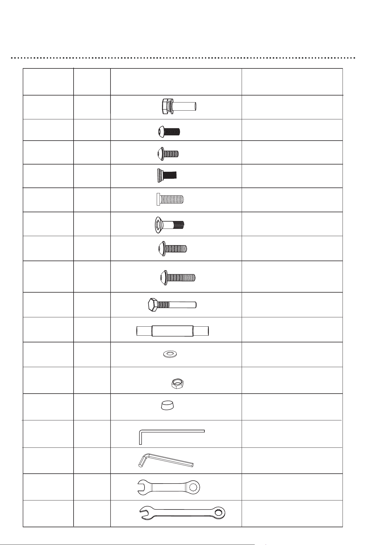
HARDWARE
16+1
AA
BB
CC
DD
EE
FF
GG
HH
JJ
KK
LL
MM
NN
OO
PP
QQ
RR
Part QTY PIECE DESCRIPTION
14+1
177+10
8+1
24+2
8+1
14+1
16+1
8+1
4+1
4+1
4+1
4+1
8+1
2
1
1
M8*25 bolt with washer
M6*8 bolt
M6*15 bolt with washer
M6*15 bolt
M6*10 bolt
M6*20 bolt
M6*35 bolt with washer
M6*65 bolt with washer
M8*75 bolt
Double-end bolt
washer
Nut
Nut cap
Ground stake
Allen wremch
Hex wrench
Wrench
9
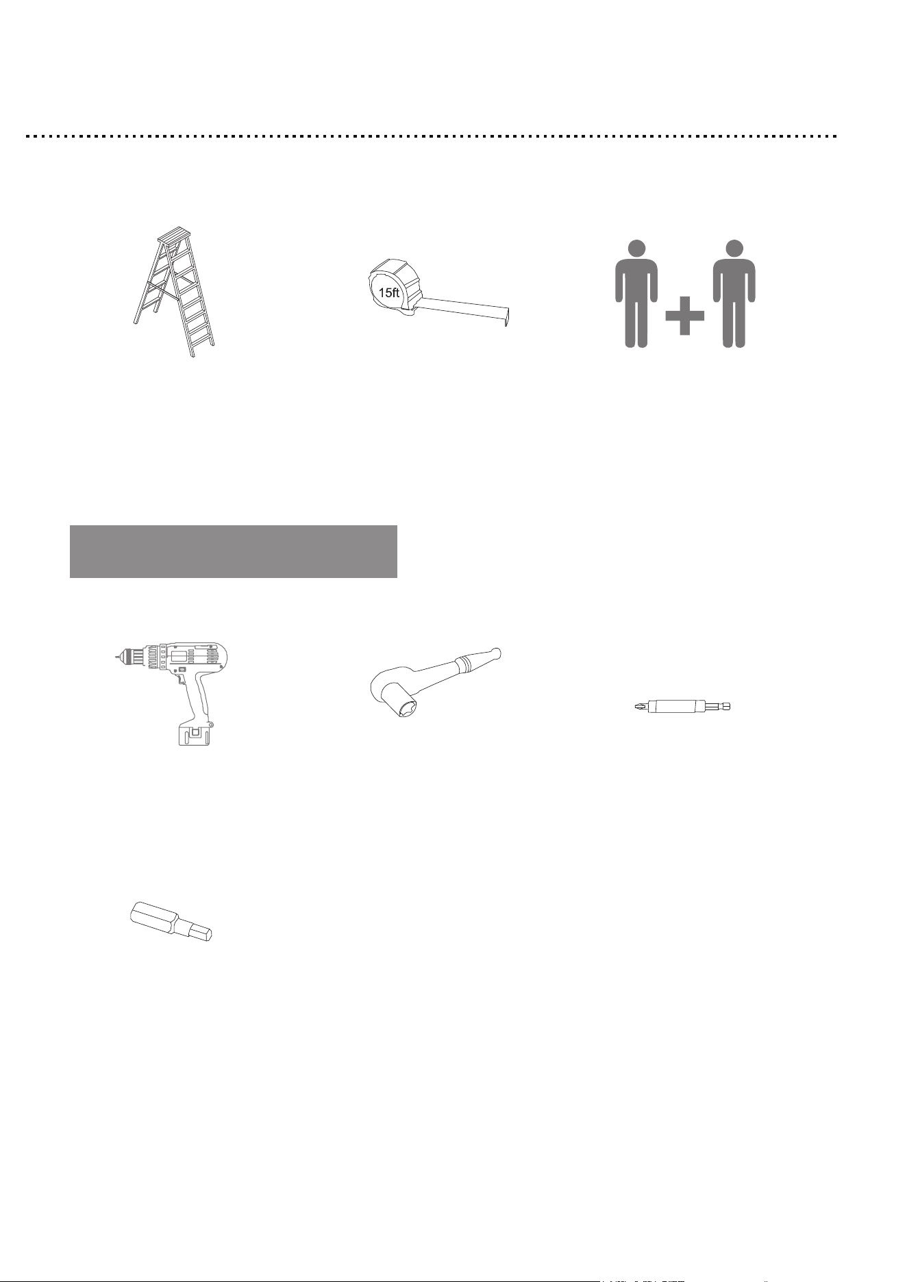
TOOLS REQUIRES
10
8’ (2.4 m) Ladder
(QTY. 2 recommended)
15’ (4.6 m) Tape measure
2
people
Cordless drill or
driver with 4 mm
hex head bit
Socket wrench with
10 mm socket
Driver bit extension
(4” recommended)
4 mm
hex bit
RECOMMENDED TOOLS

Step 1
ATTENTION: To prevent damage during assembly,please use either the
box carton or another soft material as a working surface.
1. Insert the Foot plate cover(C) into the Post leg (A1).
2. Attach the Foot plate (B) to the Post leg (A1) with M6*15 Bolt
with washer (CC).
3. Tighten all bolts by using Allen wrench (PP).
4. Repeat this step for the remaining Post legs (A2) & (A3).
11
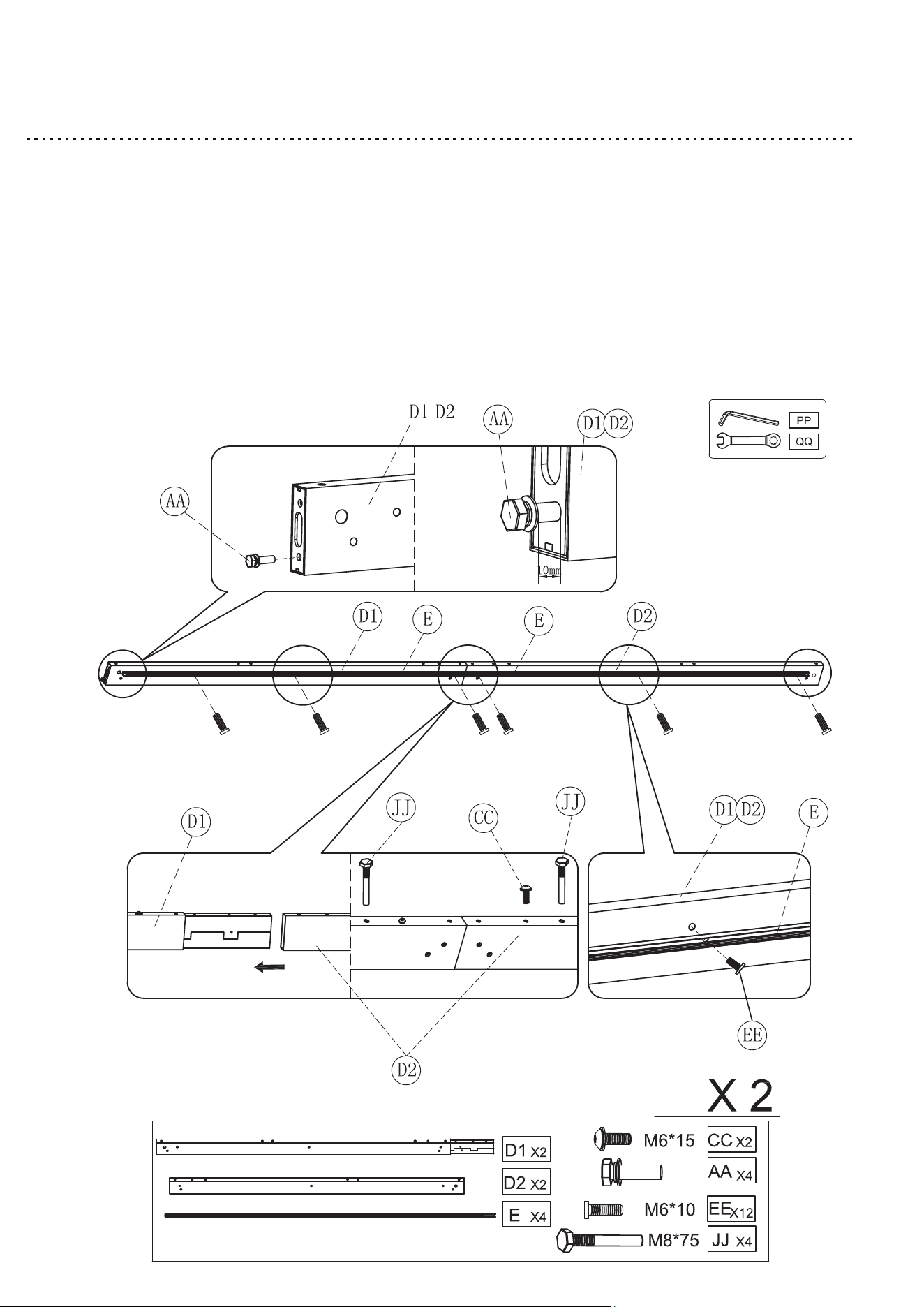
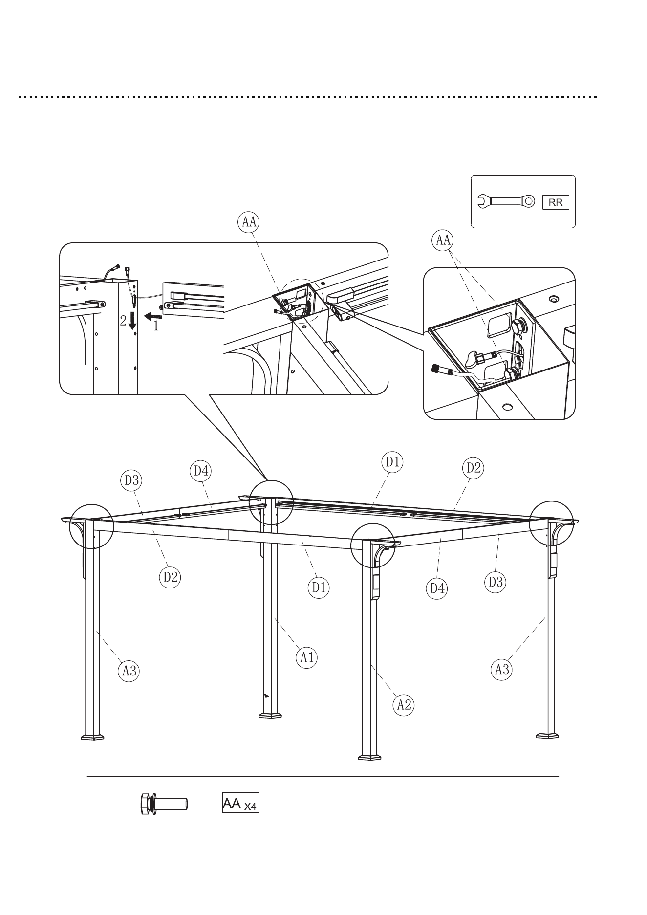
Step 2
1. Insert the Long beam (D2) into the Long beam (D1) with M6*15 bolt
with washer (CC) & M8*75 bolt (JJ).
2. Attach the Light strip tube (E) to the Long beam (D1) & (D2) with
M6*10 bolt (EE).
3. Use the M8*25 bolt (AA) on both sides of Long beam (D1) & (D2).
4. Tighten all bolts by using Allen wrench (PP) & Hex wrench (QQ).
5. Repeat this step for the remaining Long beam (D1) & (D2).
12
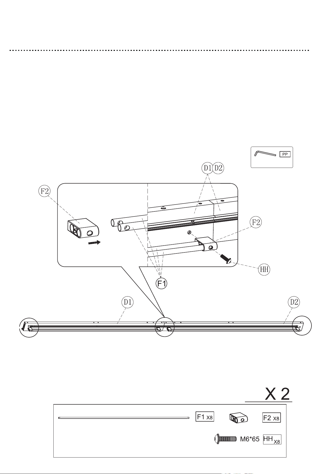
Step 3
1. Insert the Plastic (F2) into the two Long fiberglass rod (F1).
2. Attach the two Long fiberglass rod (F1) to the Long beam (D1) & (D2)
with M6*65 bolt with washer (HH).
3. Tighten all bolts by using Allen wrench (PP).
4. Repeat this step for the remaining Long fiberglass rod (F1).
13
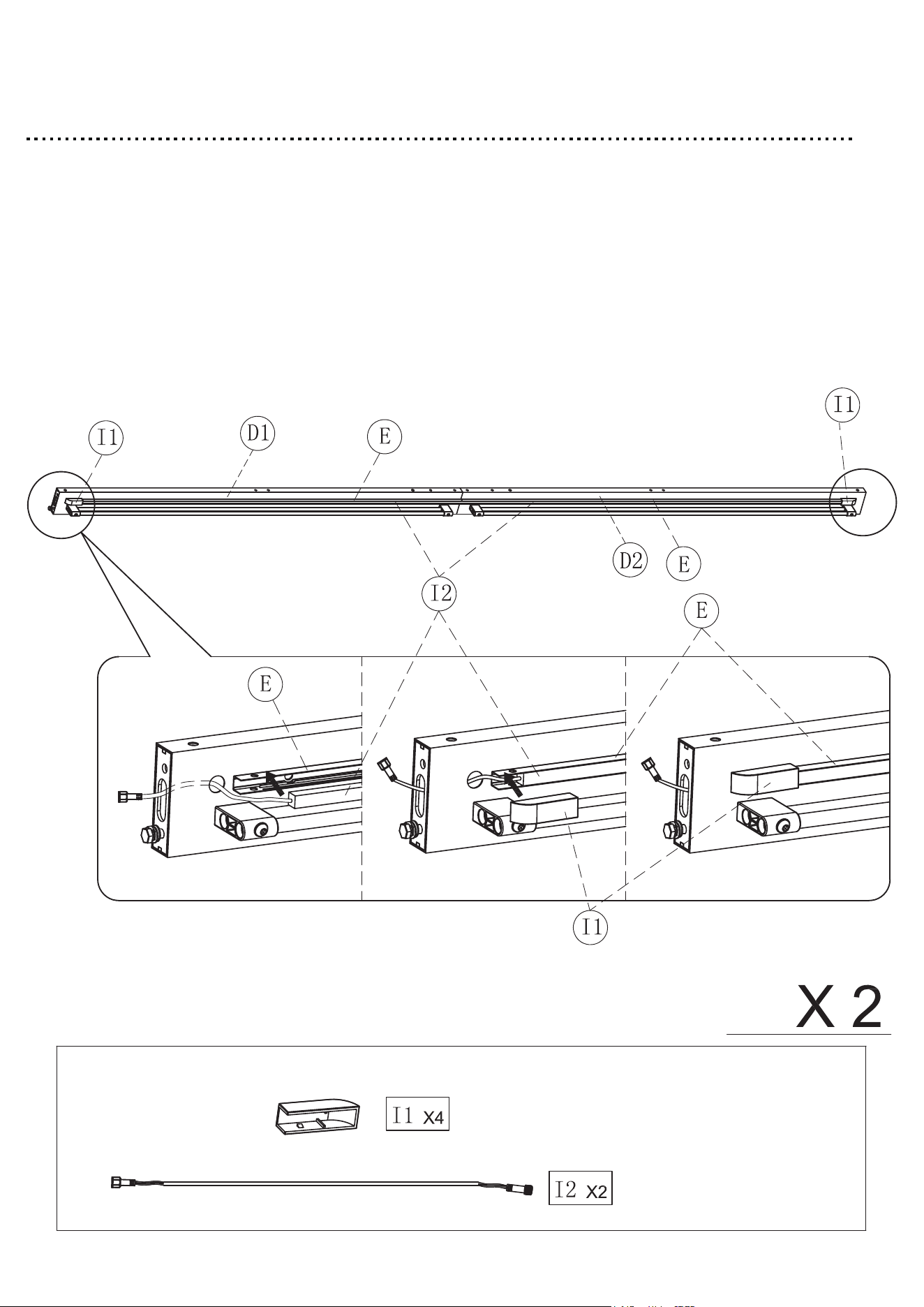
Step 4
1. Insert the Light bar (I2) into the Light strip tube (E).
2. Insert the Light bar plastic part (I1) into the Light strip tube (E).
3. Repeat this step for the remaining Light bar (I2)
14
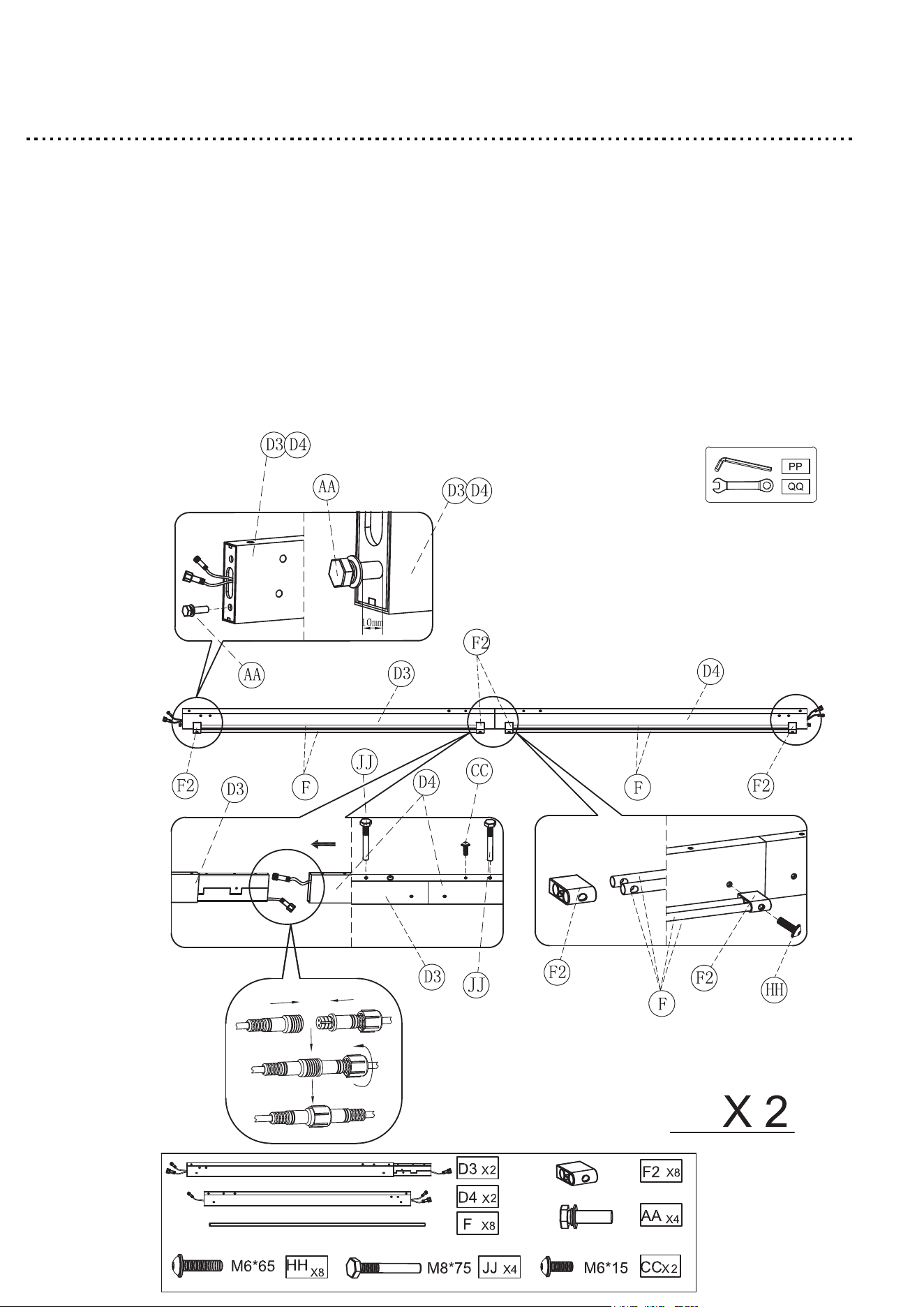
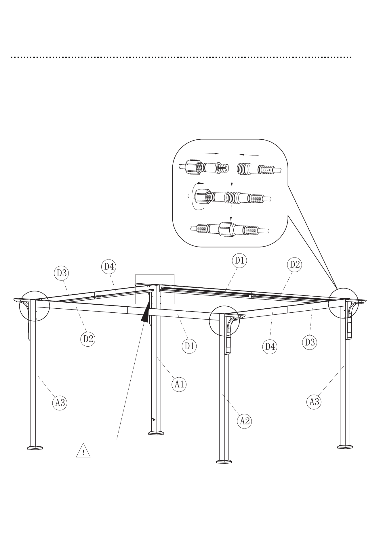
Step 5
1. Connect the wires on the short beam.
2. Insert the Short beam (D4) into the Short beam (D3) with M6*15 bolt
with washer (CC) & M8*75 bolt (JJ).
3. Insert the Plastic (F2) into the two Short fiberglass rod (F).
4. Attach the two Short fiberglass rod (F) to the Short beam (D3) & (D4)
with M6*65 bolt with washer (HH).
5. Use M8*25 bolt with washer (AA) on both sides of Short beam (D3) & (D4).
6. Tighten all bolts by using Allen wrench (PP) & Hex wrench (QQ).
7. Repeat this step for the remaining Short beam (D3) & (D4).
15
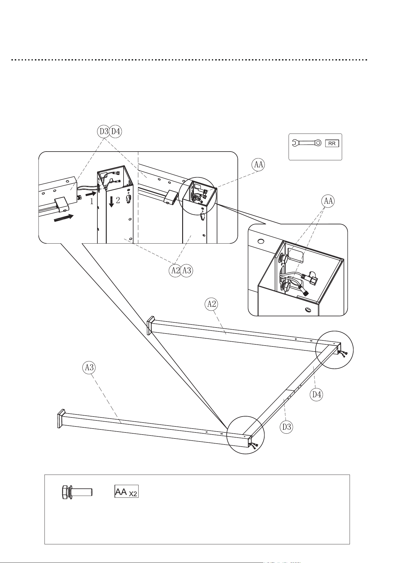
Step 6
1. Attach the Short beam (D3) & (D4) to the Post leg (A3)& (A2) with
M8*25 bolt with washer (AA).
2. Tighten all bolts by using Wrench (RR)
16
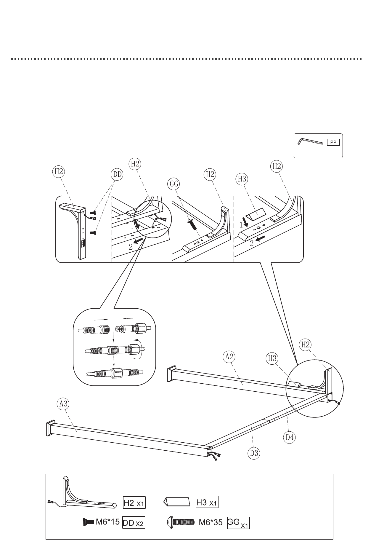
Step 7
1. Use the M6*15 bolt (DD) on the Corner connector (H2).
2. Connect the wires of Short beam (D4) & Corner connector (H2), then insert the
wires into the Post leg (A2).
3. Insert the Corner connector (H2) into the Post leg (A2) with M6*35
bolt with washer (GG).
4. Tighten all bolts by using Allen wrench (PP).
5. Insert the Downlight (H3) into the Corner connector (H2).
17
Step 8
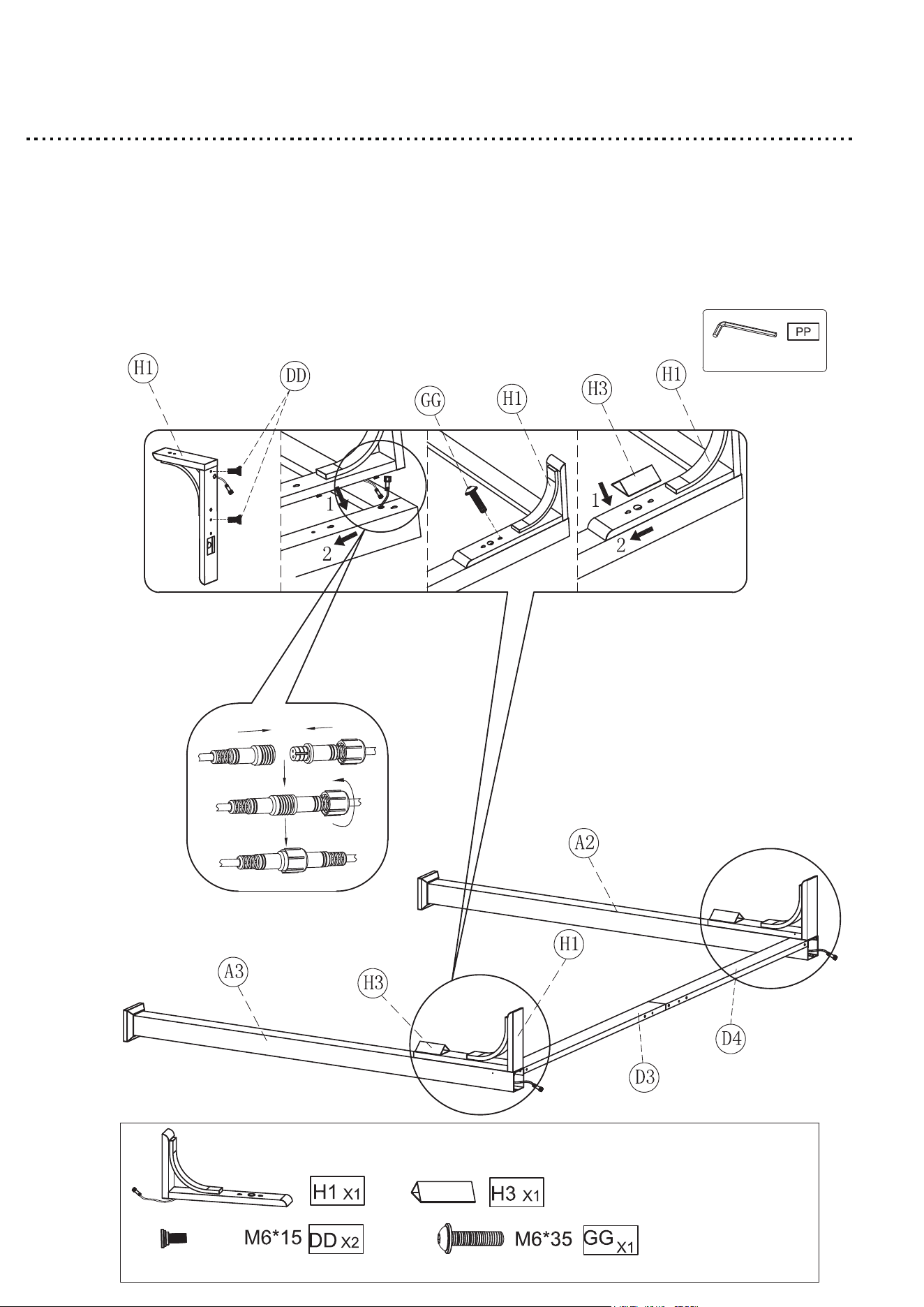
1. Use the M6*15 bolt (DD) on the Corner connector (H1).
2. Connect the wires of Short beam (D3) & Corner connector (H1), then insert the
wires into the Post leg (A3).
3. Insert the Corner connector (H3) into the Post leg (A3) with M6*35
bolt with washer (GG).
5. Insert the Downlight (H3) into the Corner connector(H1) .
4. Tighten all bolts by using Allen wrench (PP).
18
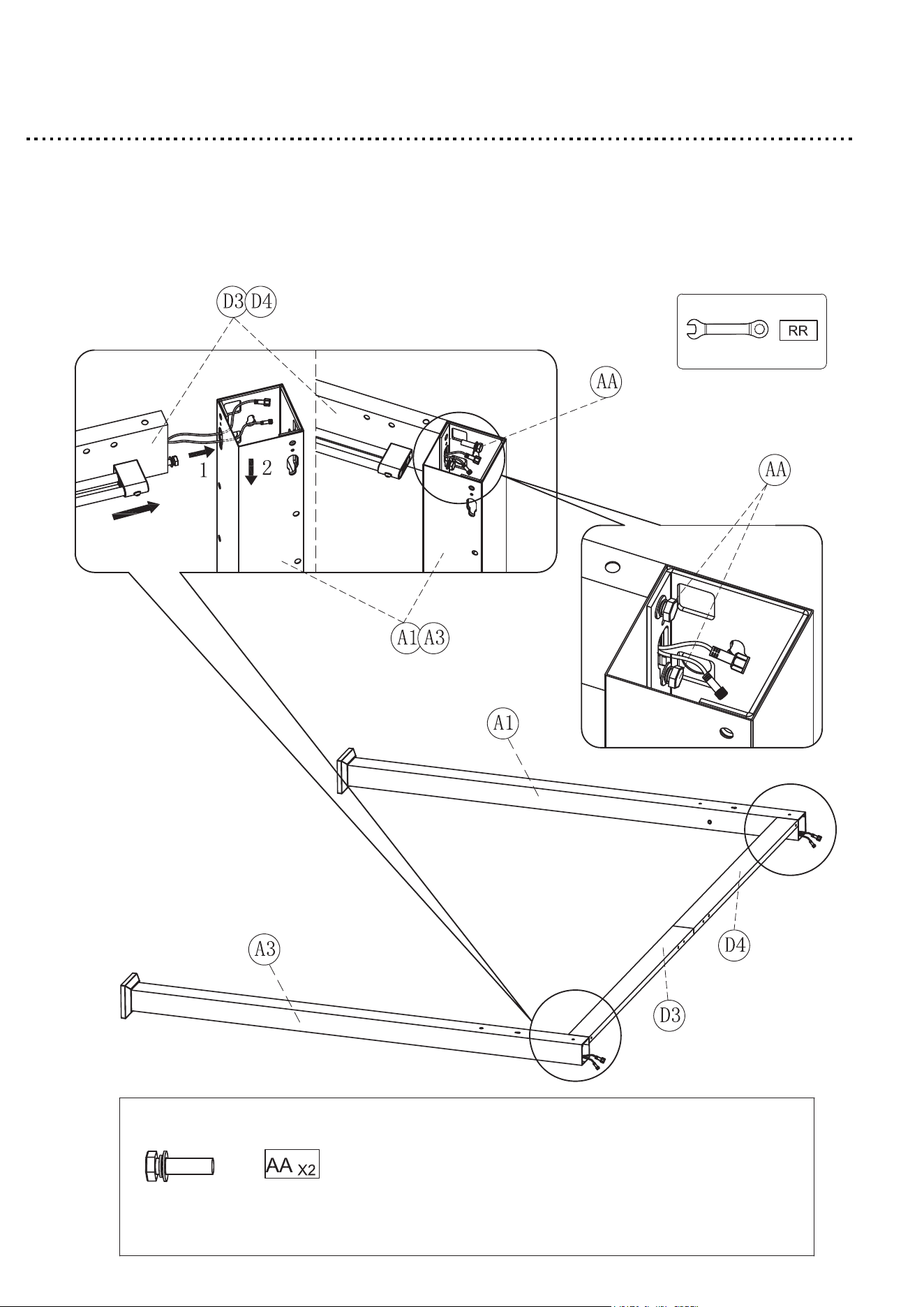
Step 9
1. Attach the Short beam (D3) & (D4) to the Post leg (A1) & (A3) with
M8*25 Bolt with washer (AA).
2. Tighten all bolts by using Wrench (RR).
19
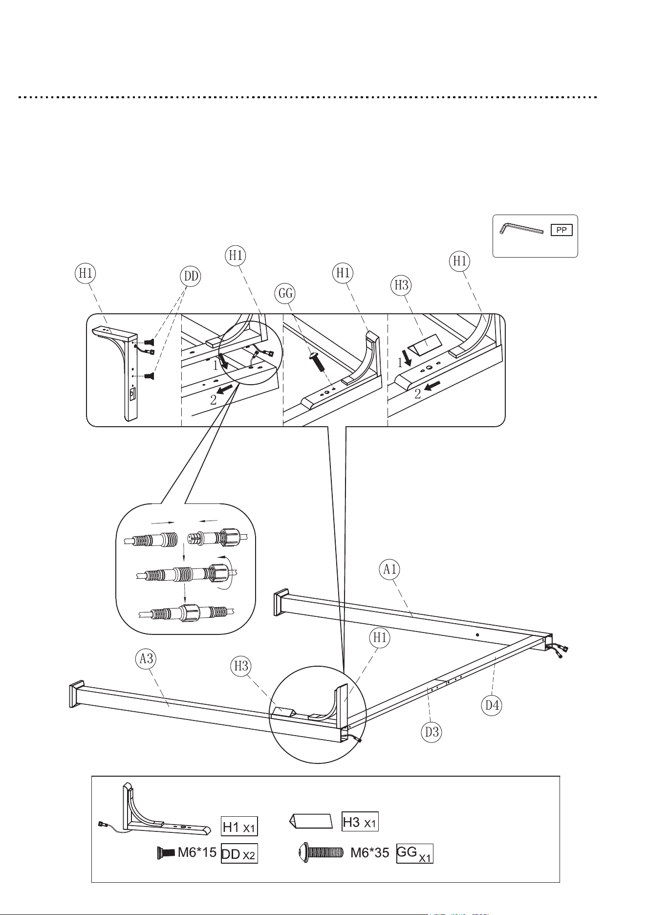
Step 10
1. Use the M6*15 bolt (DD) on the Corner connector (H1).
2. Connect the wires of Short beam (D3) & Corner connector (H1), then insert the
wires into the Post leg (A3).
3. Insert the Corner connector (H1) into the Post leg (A3) with M6*35 bolt
with washer (GG).
5. Insert the Downlight (H3) into the Corner connector (H1).
4. Tighten all bolts by using Allen wrench (PP).
20
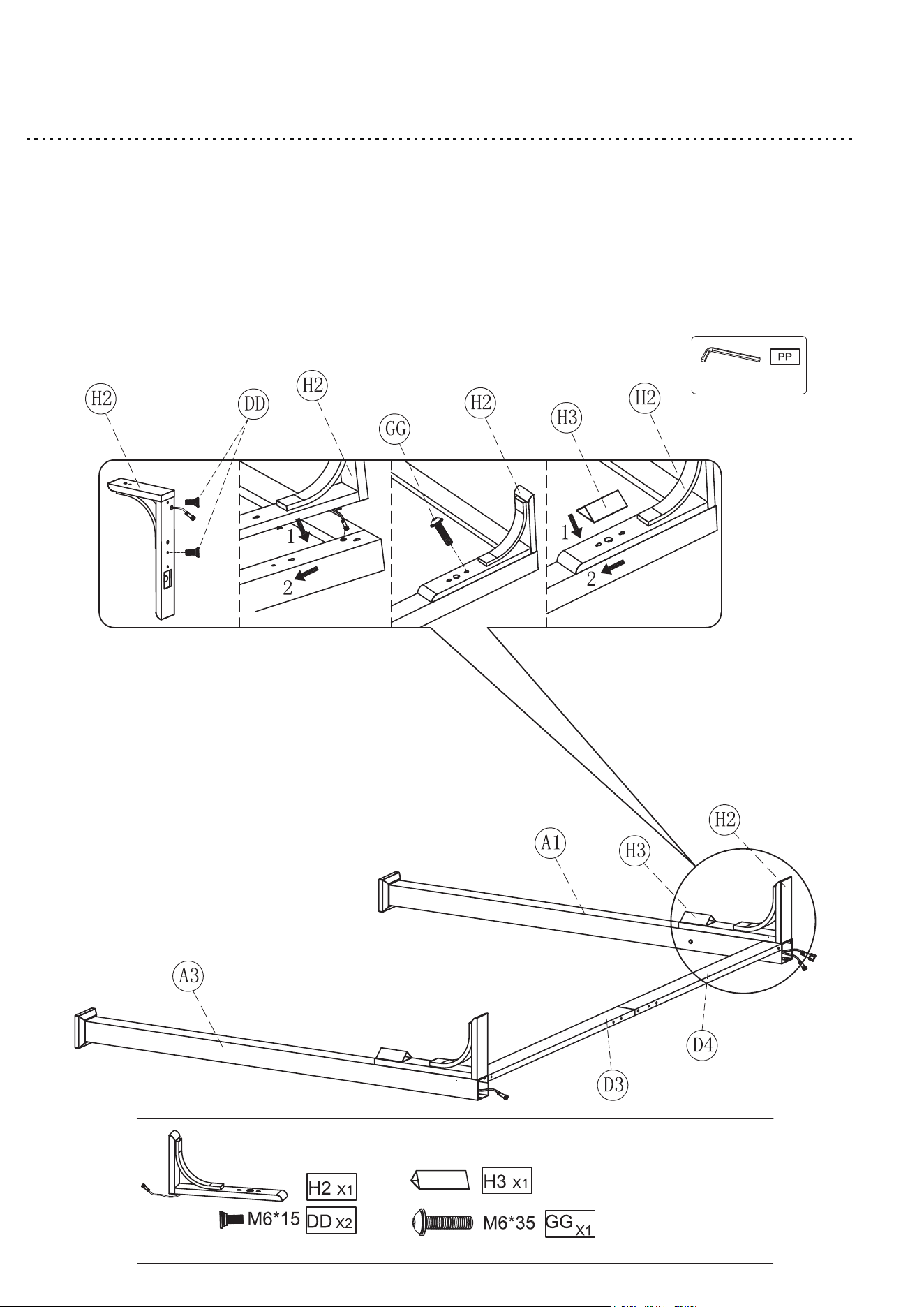
Step 11
1. Use the M6*15 bolt (DD) on the Corner connector (H2).
2. Attach the Corner connector (H2) to the Post leg (A1) with M6*35
bolt with washer (GG).
3. Tighten all bolts by using Allen wrench (PP).
4. Insert the Downlight (H3) into the Corner connector (H2).
21
Step 12
1. Insert the Long beam (D1) & (D2) into the Post leg (A1) with M8*25
bolt with washer (AA).
2. Repeat this step for all post leg (A2) & (A3).
3. Tighten all bolts by using Wrench (RR).
22
Step 13
1. Connect the wires on the post leg (A3) & (A2).
NOTE: This position is not wired.
23
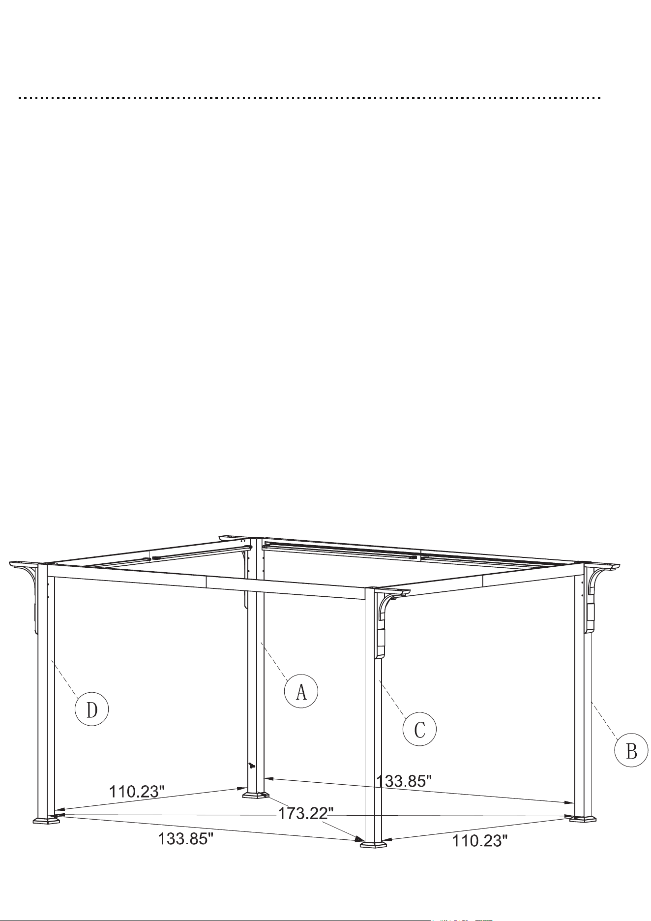
Step 14
Squaring the gazebo frame is a very important step to ensure easier
assembly and proper fitment of parts. To do this, measure the distance
between the legs from the outside corners of each leg post in the
following order:
A to B
C to D
These measurements should be the same. Adjust legs if they are not.
A to C
B to D
These measurements should be the same. Adjust legs if they are not.
A to D
B to C
These measurements should be the same. Adjust legs if they are not.
Once the measurements above are approximately the
same, then move on to Step 15.
IMPORTANT
24
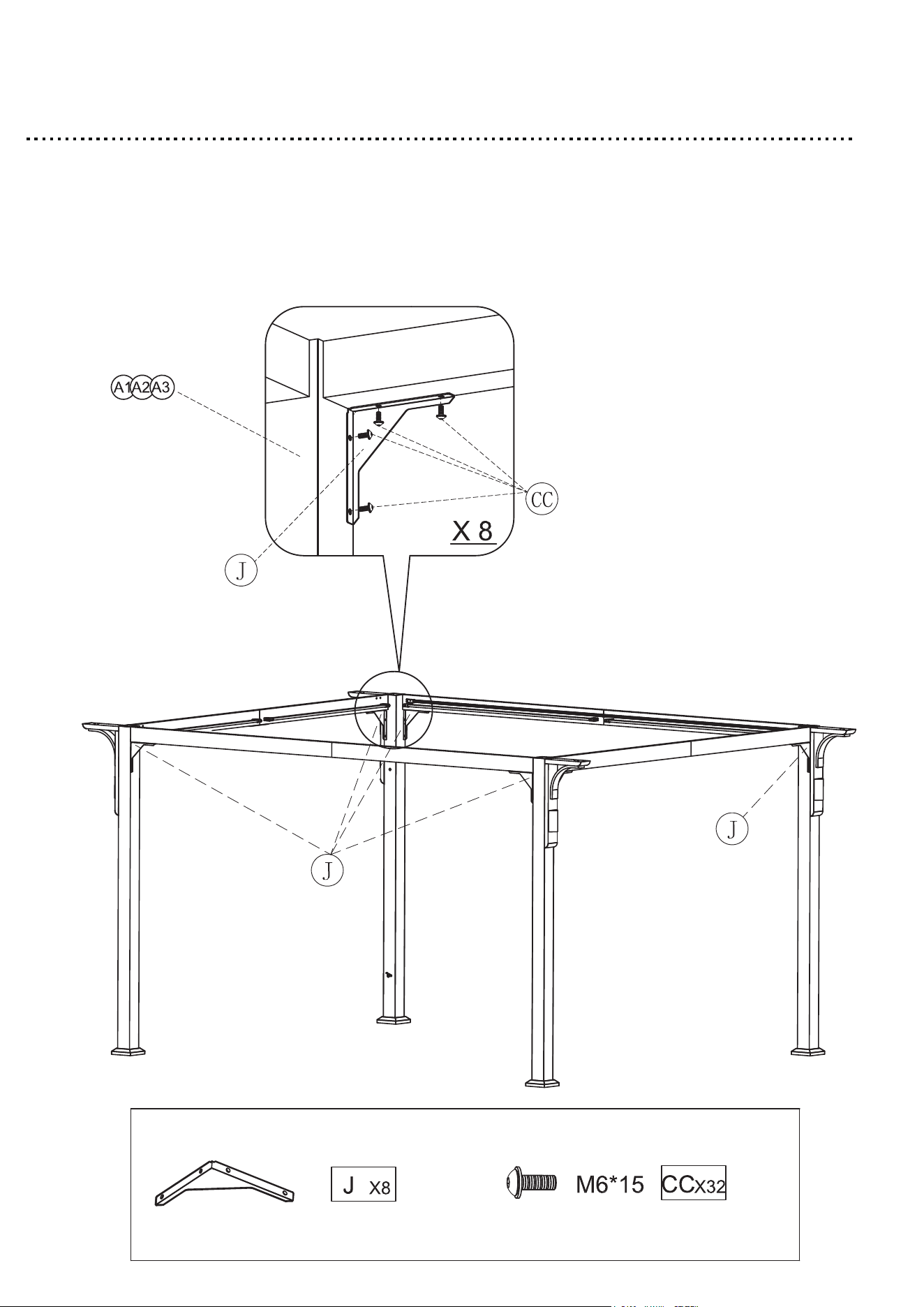
Step 15
1.Attach the Gable support (J) to the Post leg (A1) with M6*15 bolt
with washer (CC).
2.Tighten all bolts by using Allen wrench (PP).Repeat this step for
the remaining Gable support (J).
25
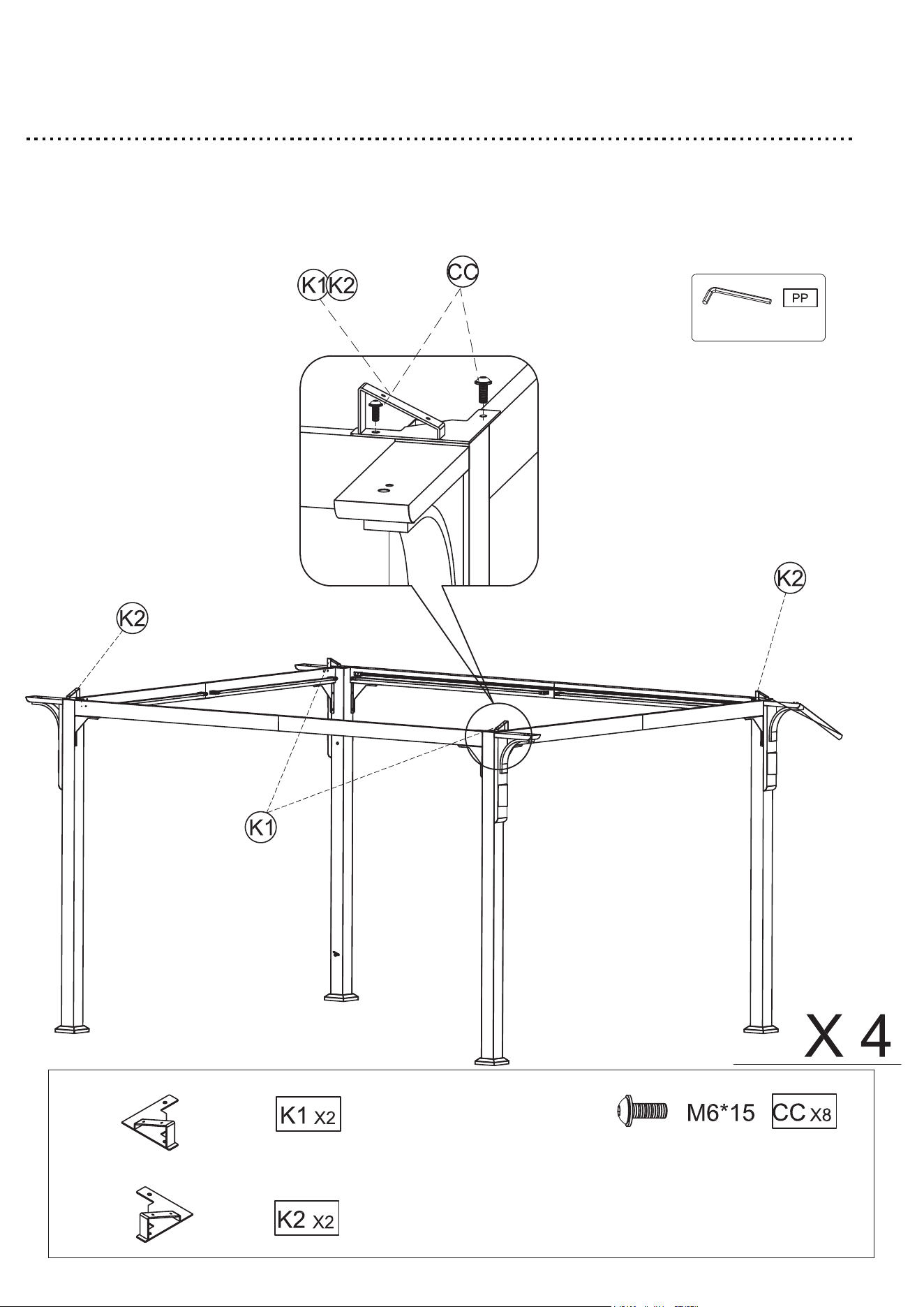
Step 16
1. Attach the Top of post leg plates (K1) & (K2) to the Post leg with
M6*15 bolt with washer (CC).
2. Tighten all bolts by using Allen wrench (PP).
26
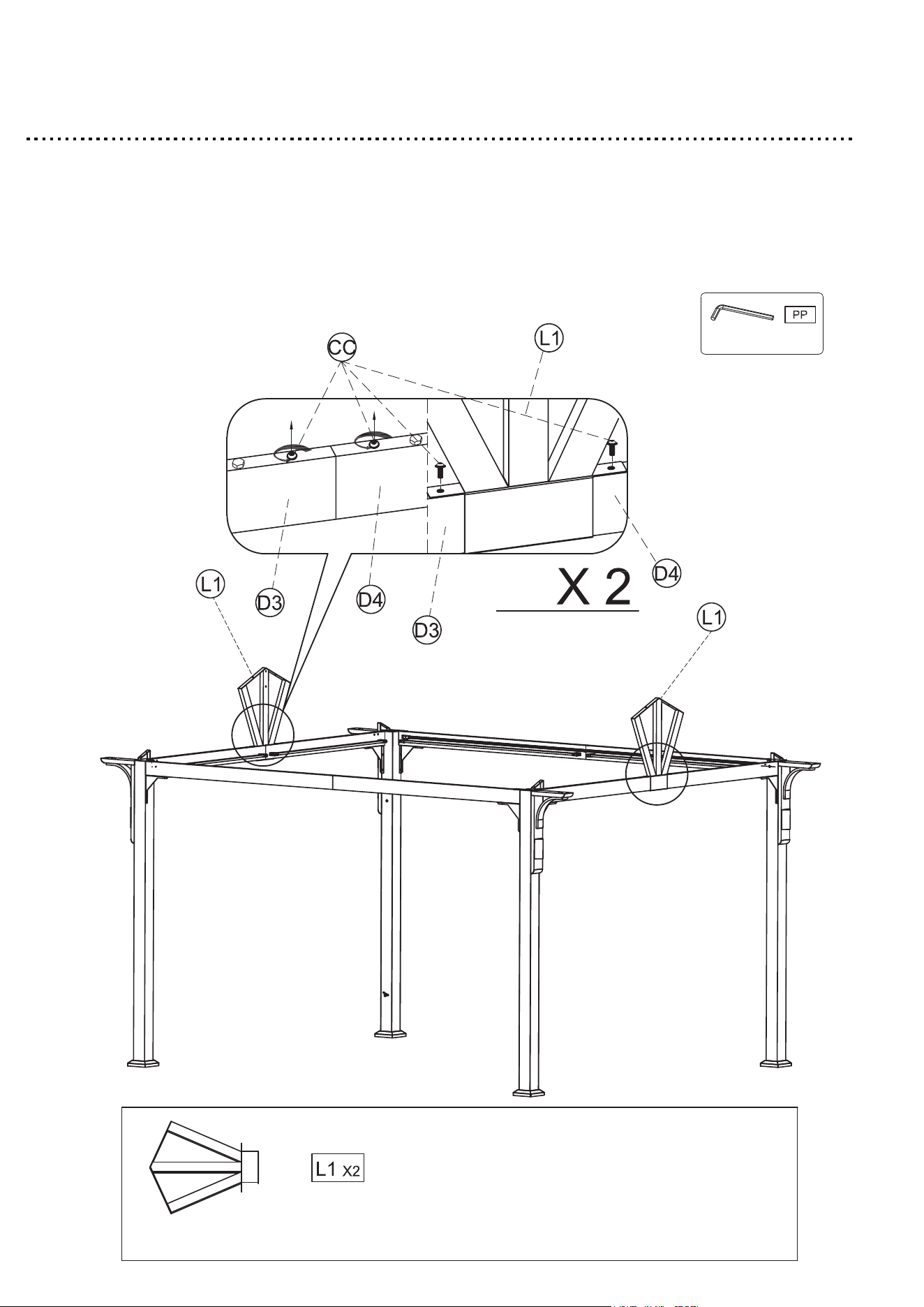
Step 17
1. Remove the M6*15 bolt with washer (CC) from theShort beam
(D3) & (D4).
2. Attach the Gable (L1) to the Short beam (D3) & (D4) with M6*15 bolt
with washer (CC).
3. Tighten all bolts by using Allen wrench (PP).
27
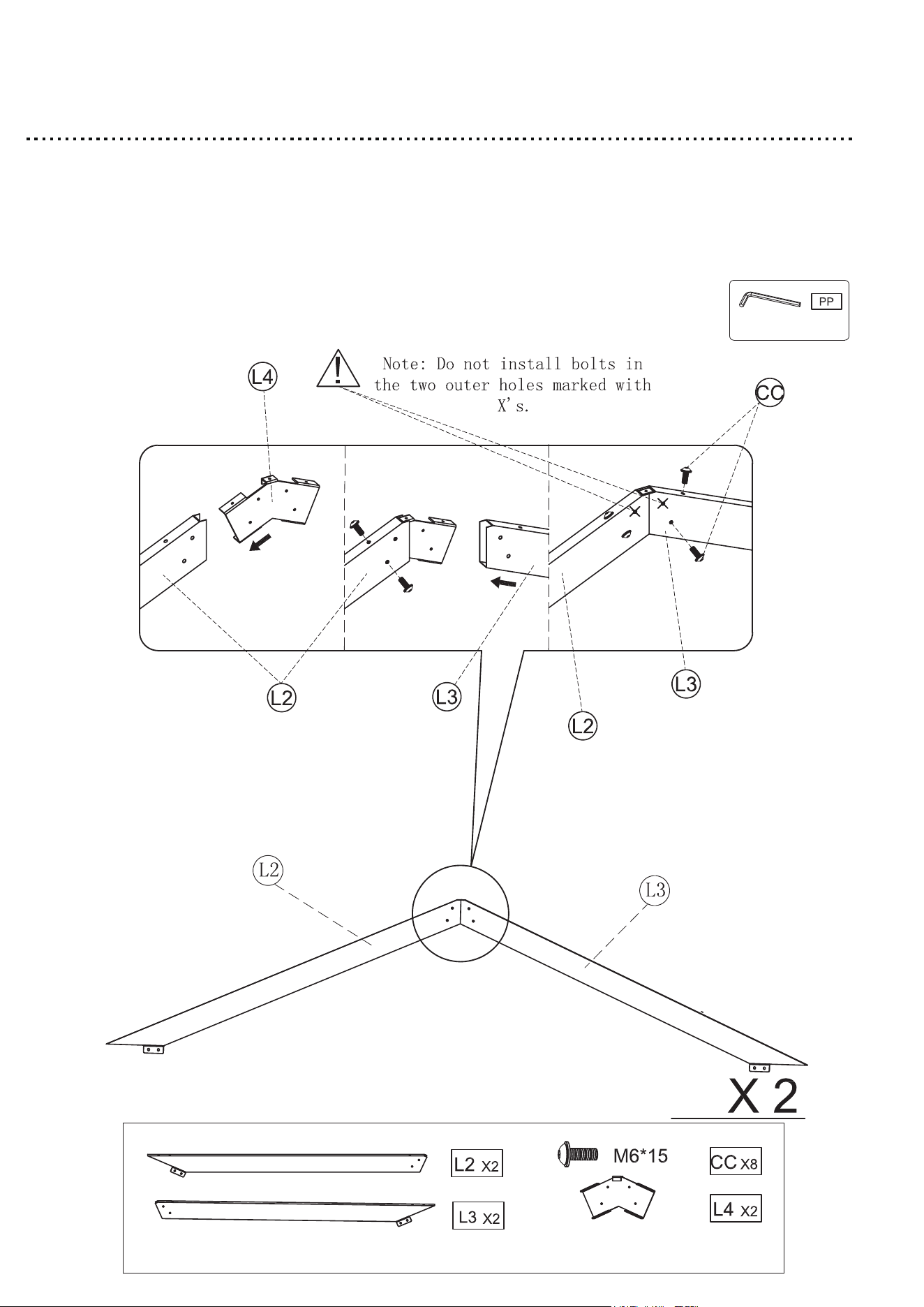
Step 18
1. Insert the Inclined beam connector (L4) into the Inclined beam (L2)
with M6 * 15 bolt with washer (CC)
2. Insert the Inclined beam (L3) into the Inclined beam (L2) with M6 * 15
bolt with washer (CC).
3. Tighten all bolts by using Allen wrench (PP).
4.Repeat this step for the remaining Inclined beam (L2) & (L3).
28
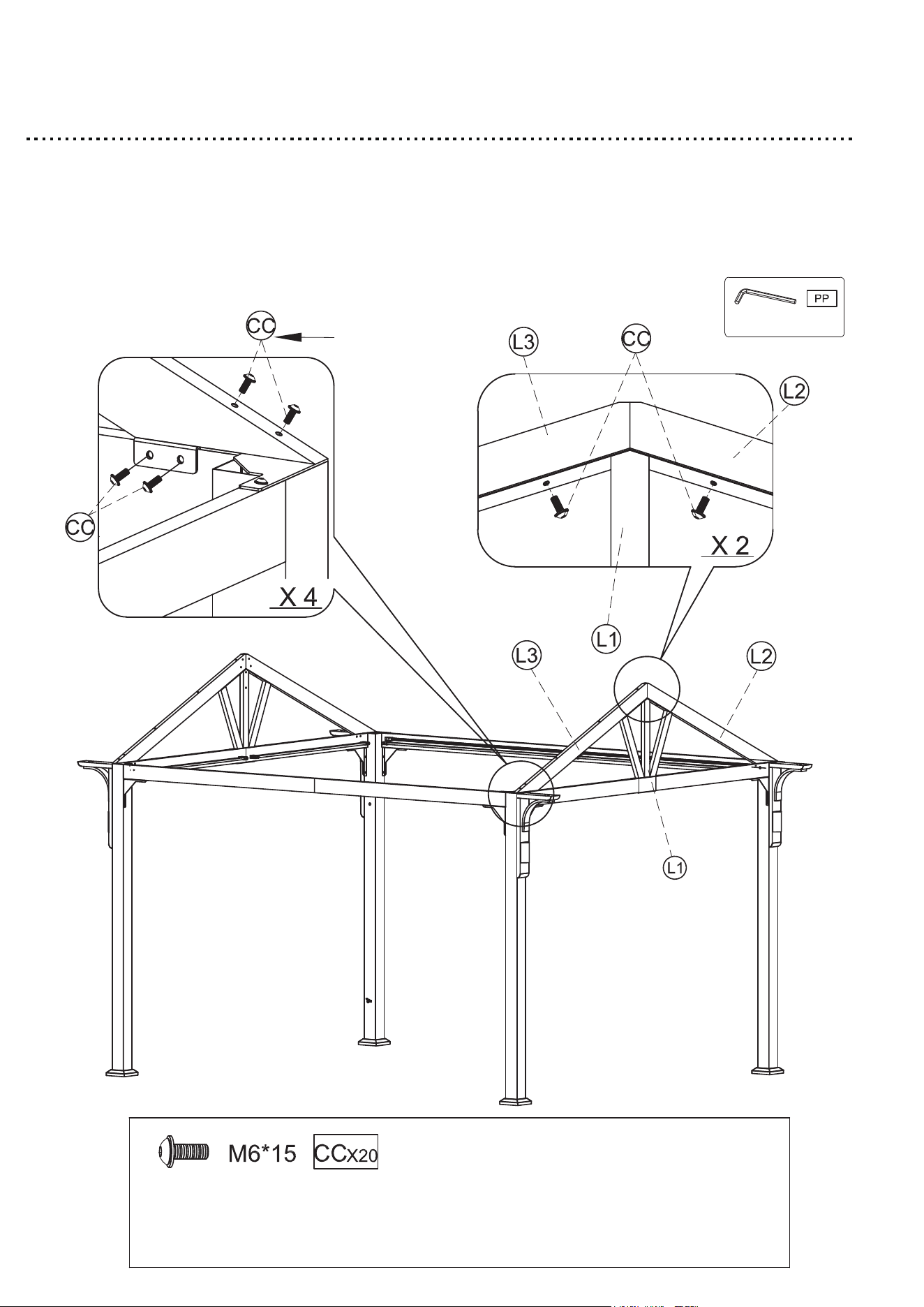
Step 19
1. Attach the Inclined beam (L2) & (L3) to the Gabel (L1) and Short beam
with M6*15 bolt with washer (CC).
2. Tighten all bolts by using Allen wrench (PP).
3. Repeat this step for the remaining Inclined beam (L2) & (L3).
29
Install first
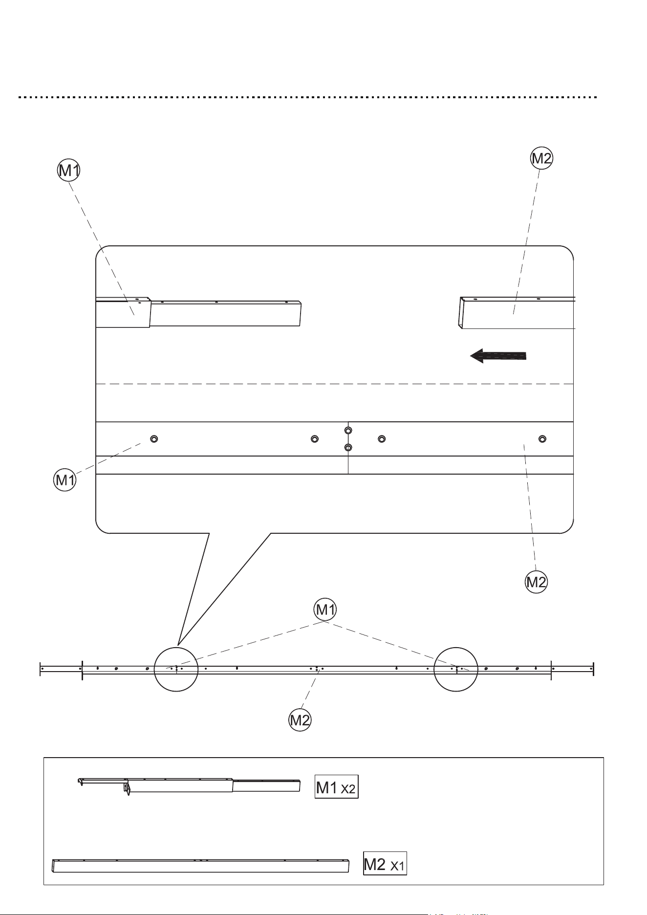
Step 20
1. Insert the two Top beam (M1) into the Top beam (M2).
30
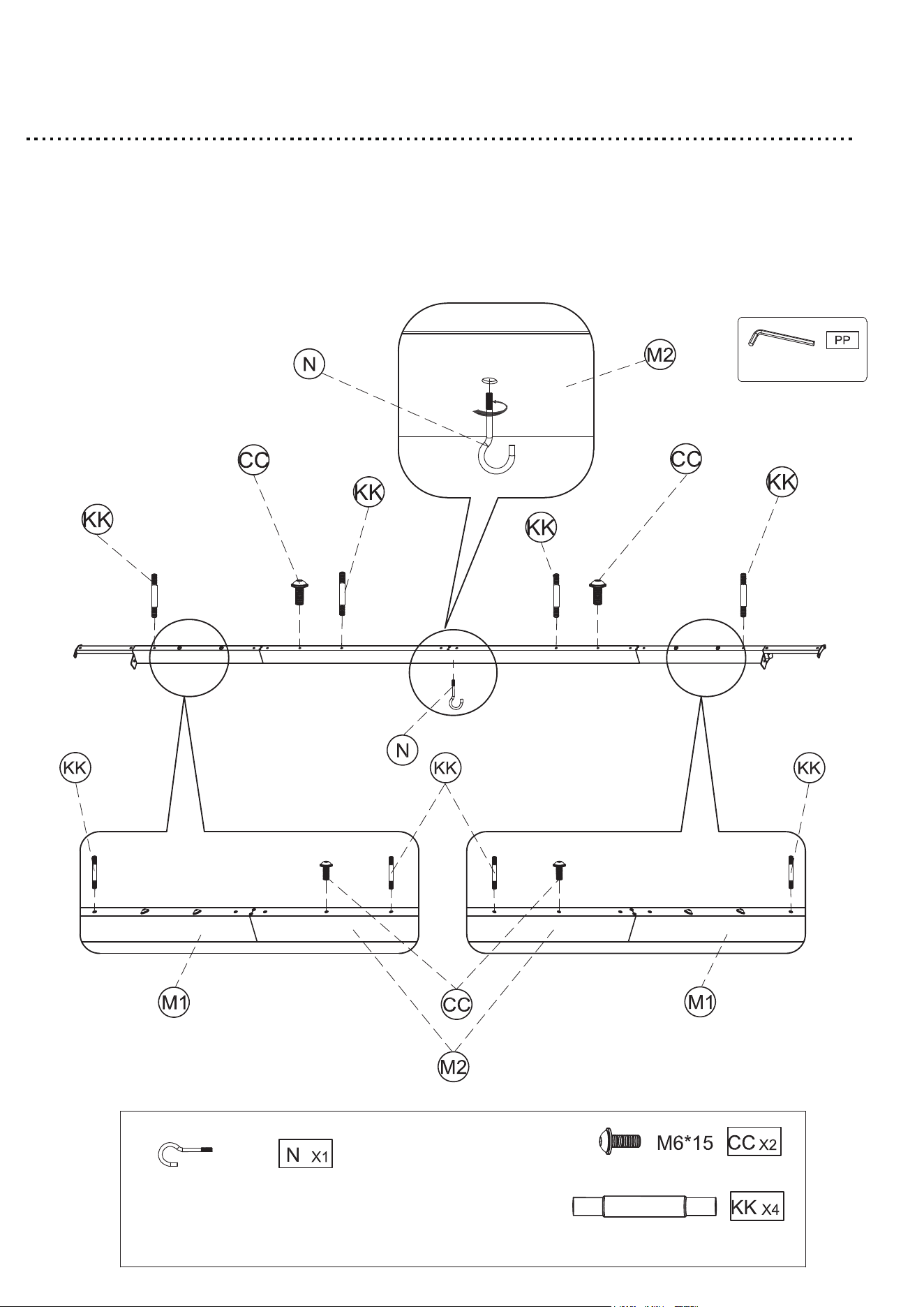
Step 21
1. Put the Double-end bolt (KK) and M6*15mm bolt with washer (CC)
into the holes of Top beam (M1) & (M2).
2. Insert the Hook (N) counterclockwise into the hole of the Top beam (M2).
3. Tighten all bolts by using Allen wrench (PP).
31
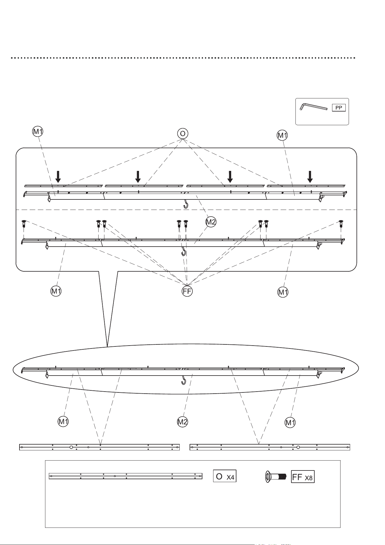
Step 22
1. Insert the Roof connector (O) into the Top beam (M1) & (M2) with
M6*20 Bolt (FF).
2. Tighten all bolts by using Allen wrench (PP).
32
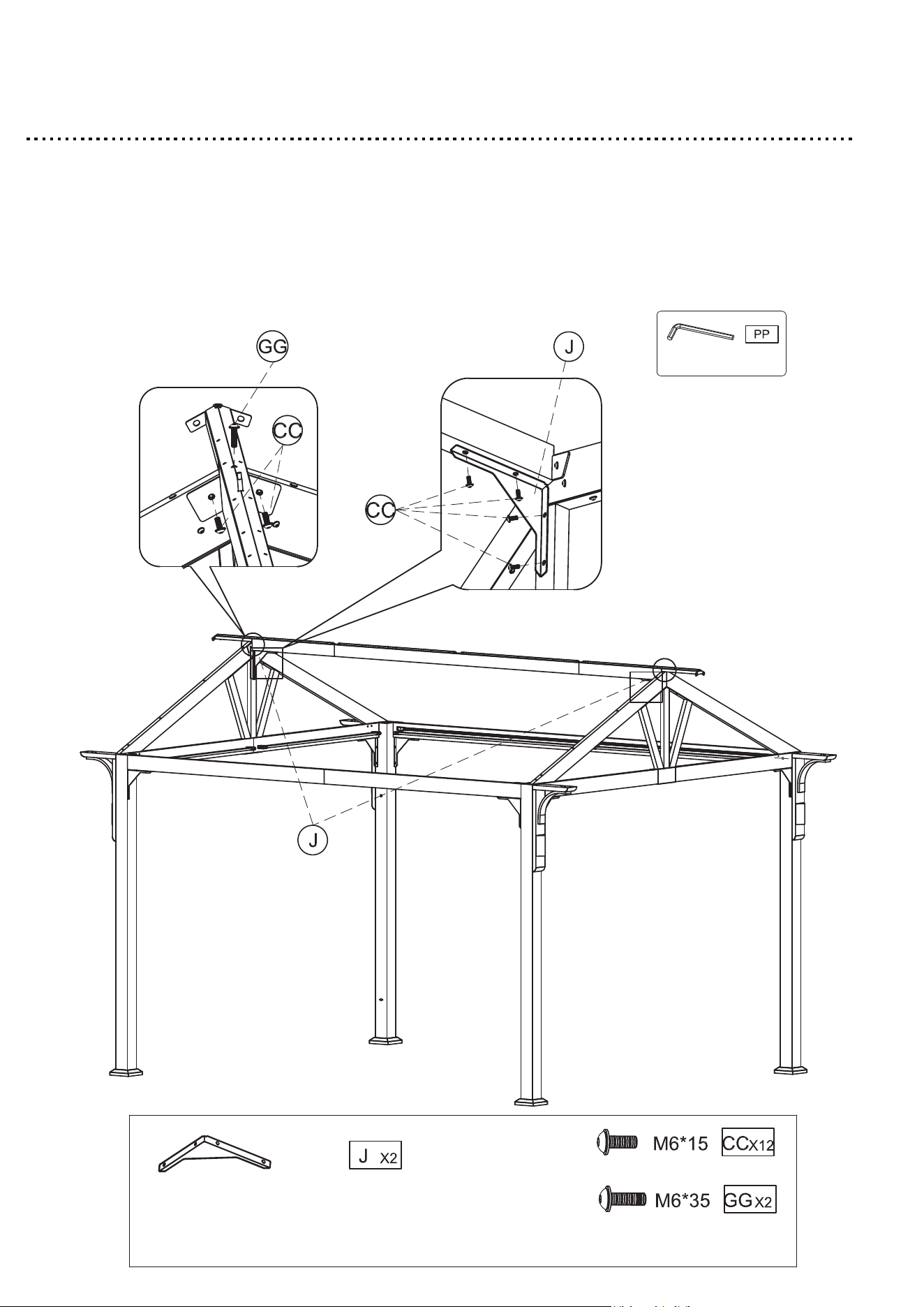
Step 23
1. Attach the Top beam (M1) & (M2) to the Inclined beam (L2) & (L3)
with M6*15 bolt with washer (CC) & M6*35 bolt with washer (GG).
2. Attach the Gable support (J) to the Top beam (M1) & Gable (L1)
with M6*15 bolt with washer (CC).
3. Tighten all bolts by using Allen wrench (PP).
33
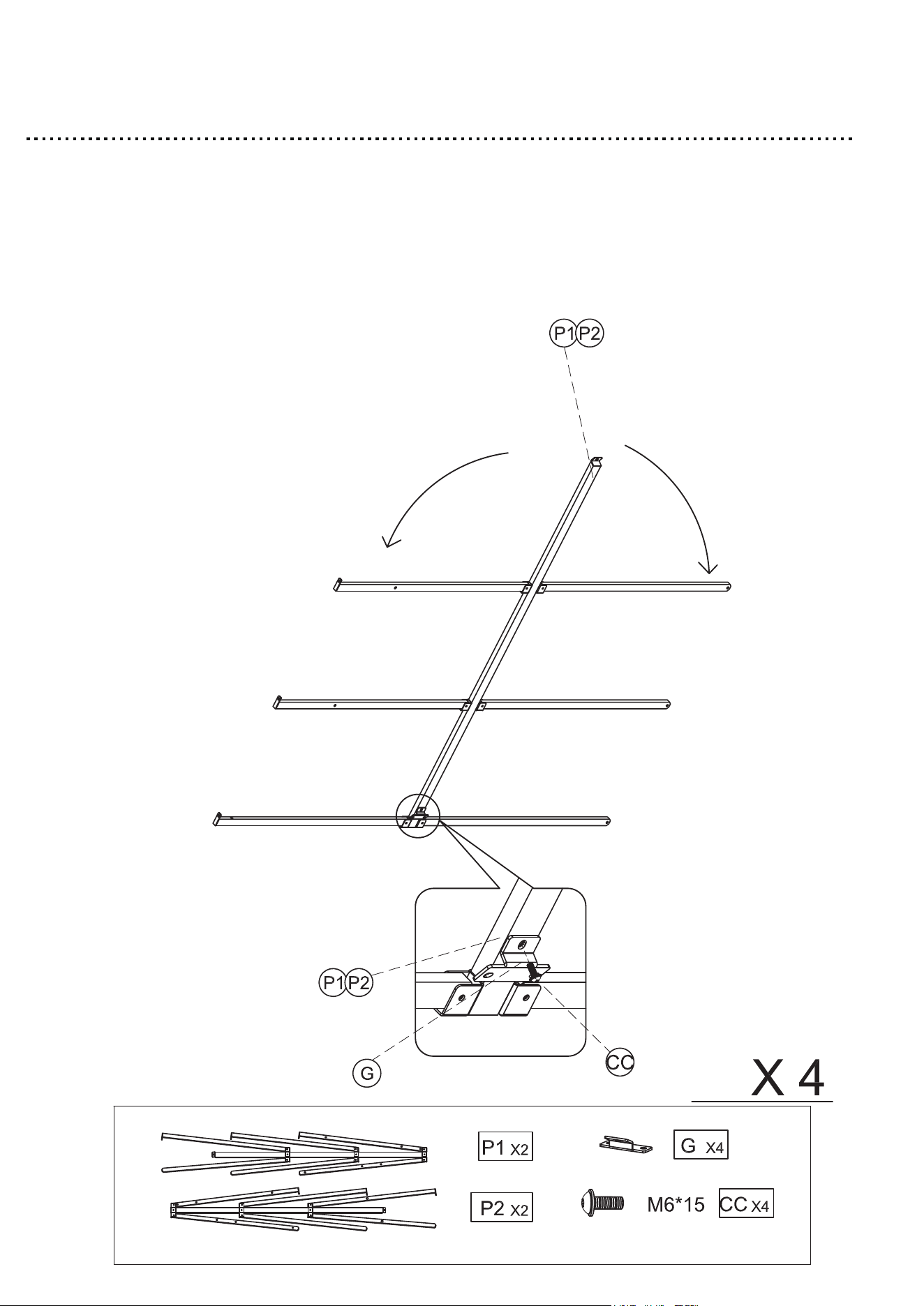
Step 24
1. Spread the Rafter branch unit (P1) & (P2) to both sides.
2. Attach the Middle inclined beam connector (G) to the Rafter branch
unit (P1) & (P2) with M6*15 bolt with washer (CC).
3. Tighten all bolts by using Allen wrench (PP).
4. Repeat this step for the remaining Middle inclined beam connector (G).
34
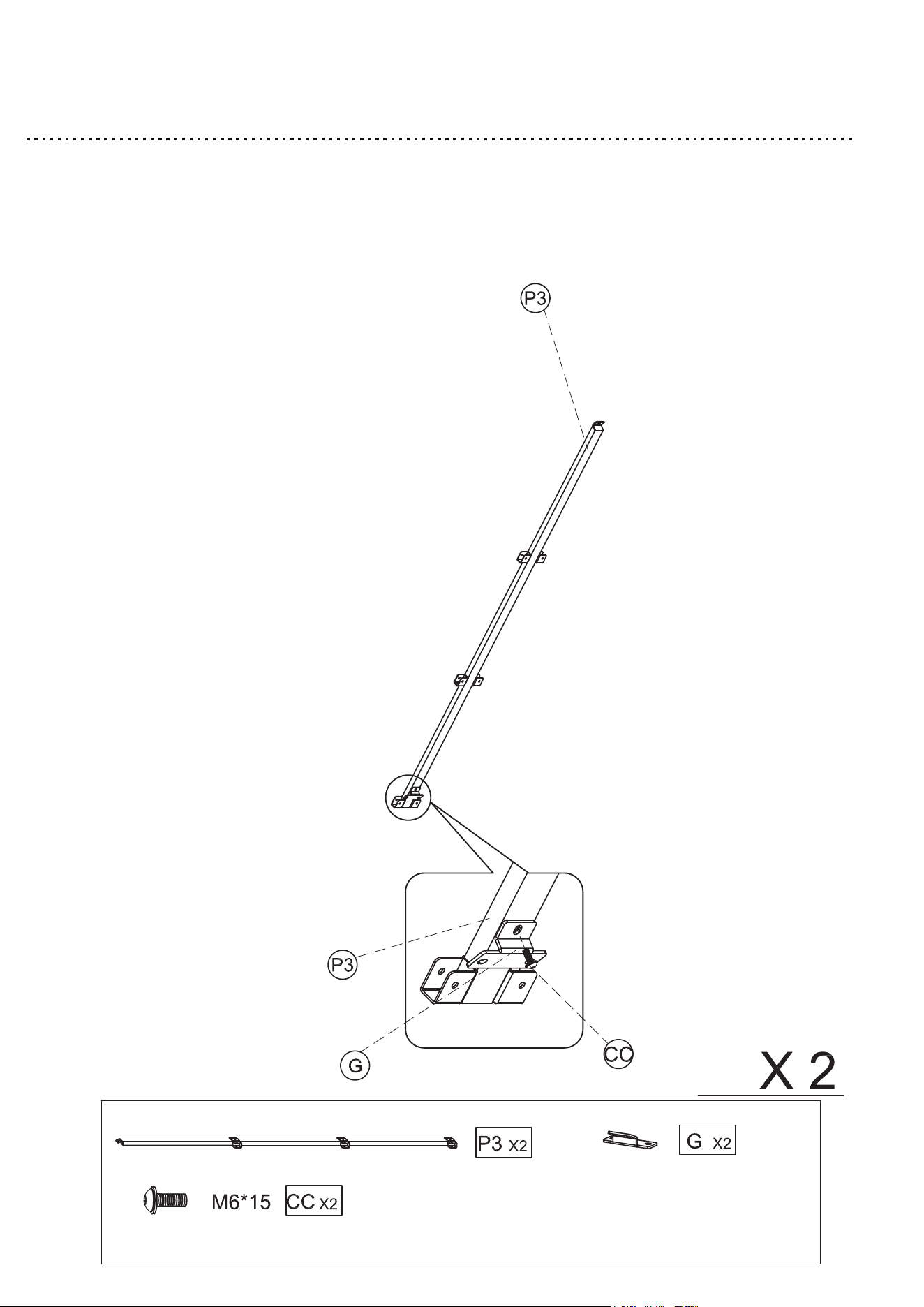
Step 25
1. Attach the Middle inclined beam connector (G) to the Rafter branch
unit (P3) with M6*15 bolt with washer (CC).
2. Repeat this step for the remaining Middle incline beam connector (G).
3. Tighten all bolts by using Allen wrench (PP).
35
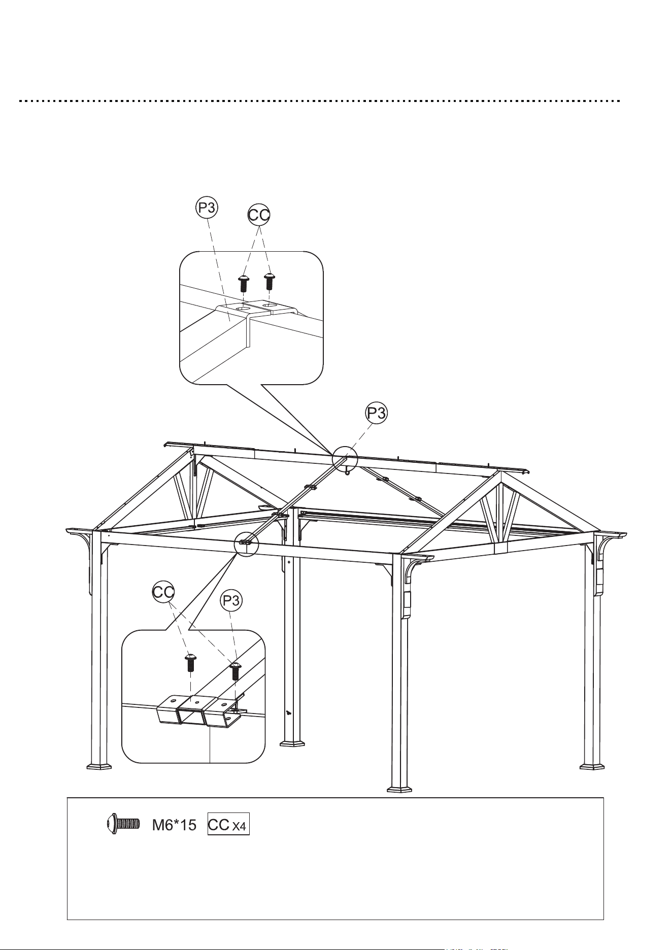
Step 26
1. Attach the Rafter branch unit (P3) to the Long beam (D1) & (D2)
with M6*15 bolt with washer (CC).
2. Tighten all bolts by using Allen wrench (PP).
36
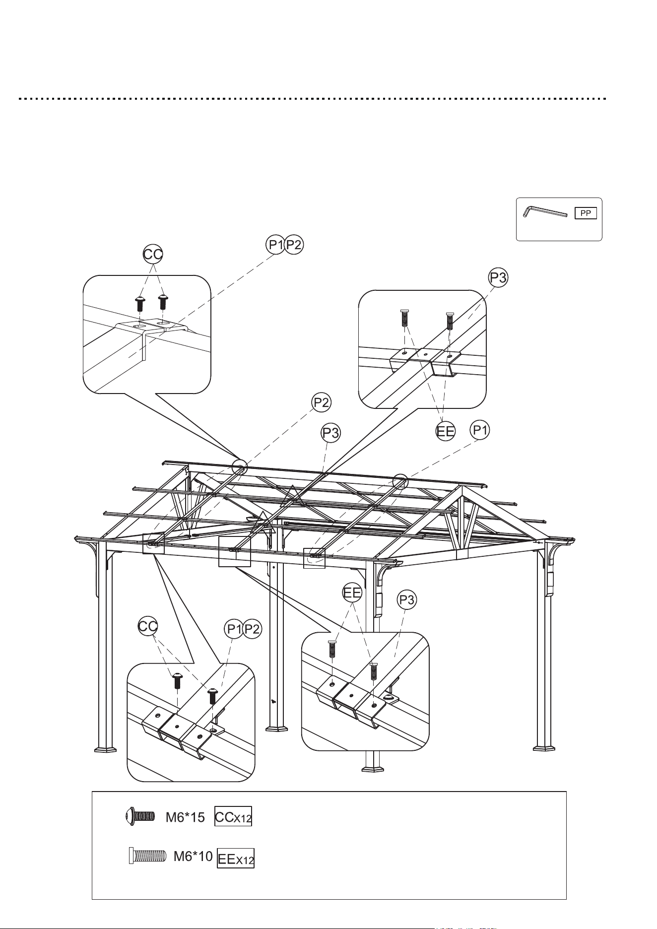
Step 27
1. Attach the Rafter branch unit (P1) & (P2) to the Top beam (M1) &
(
M2) with M6*15 bolt with washer (CC).
2. Use the M6*10 bolt (EE) to connect the Rafter branch unit (P1) &
(P2) to the Rafter branch unit (P3).
3. Tighten all bolts by using Allen wrench (PP).
37
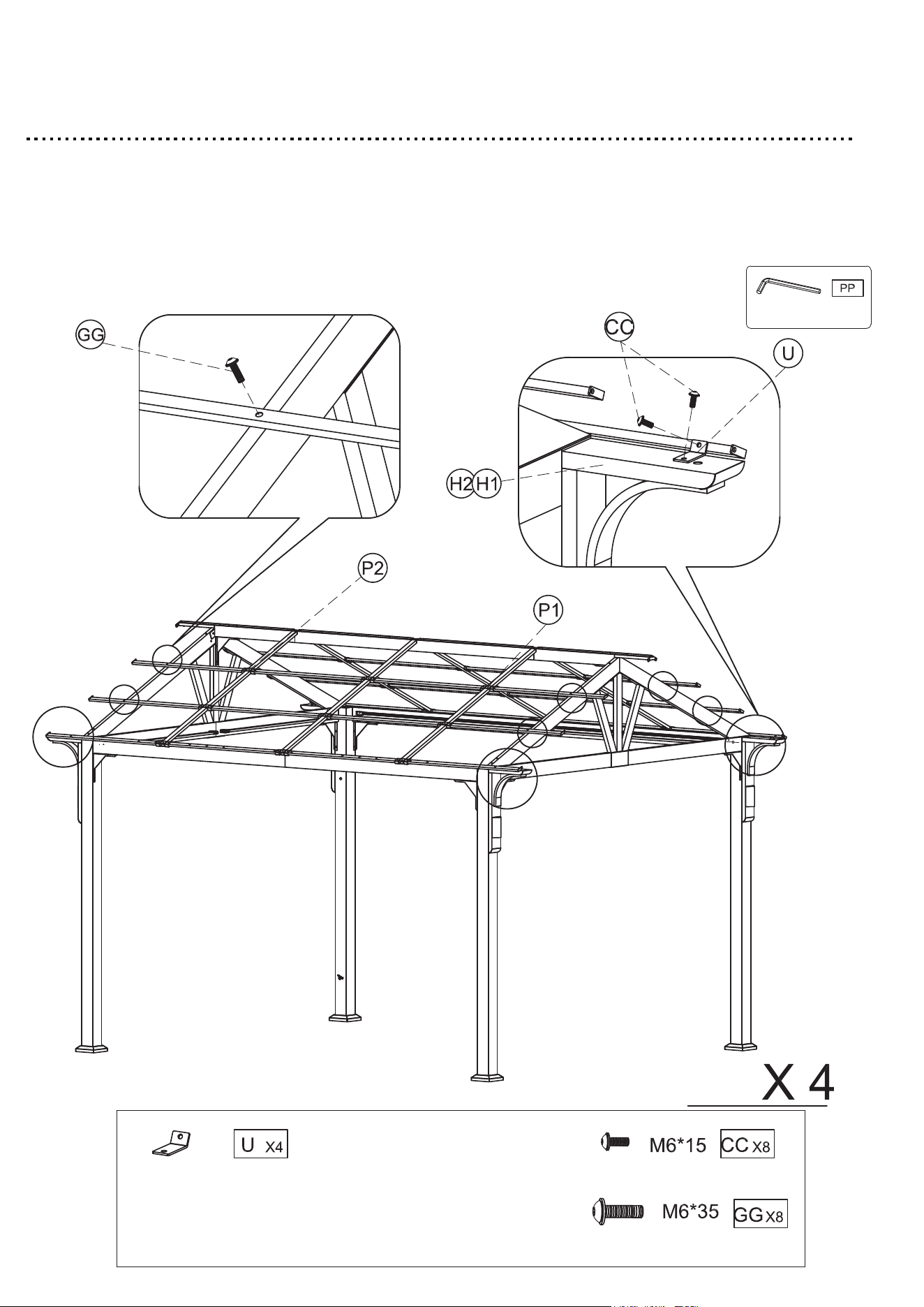
Step 28
1. Use the M6*35 bolt with washer (GG) to connect the Inclined beam
(L2) & (L3) and Rafter branch unit (P1) & (P2).
2. Attach the Corbel connector (U) to the Corner connector (H1) & (H2)
and Rafter branch unit (P1) & (P2) with M6*15 bolt with washer (CC).
3. Tighten all bolts by using Allen wrench (PP).
38
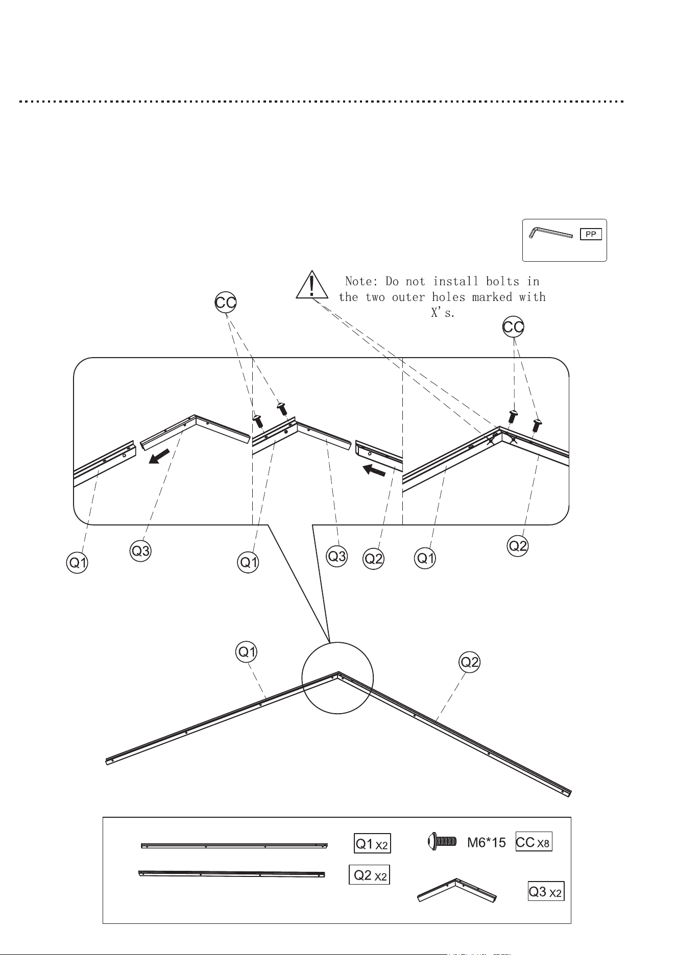
Step 29
1. Insert the Cross beam connector (Q3) into the Cross beam (Q1).
2. Insert the Cross beam (Q2) into the Cross beam connector (Q3).
3. Use the M6*15 bolt with washer (CC) to connect the Cross beam
(Q2) & (Q1).
4. Tighten all bolts by using Allen wrench (PP).
5. Repeat this step for the remaining Cross beam (Q2) & (Q1).
39
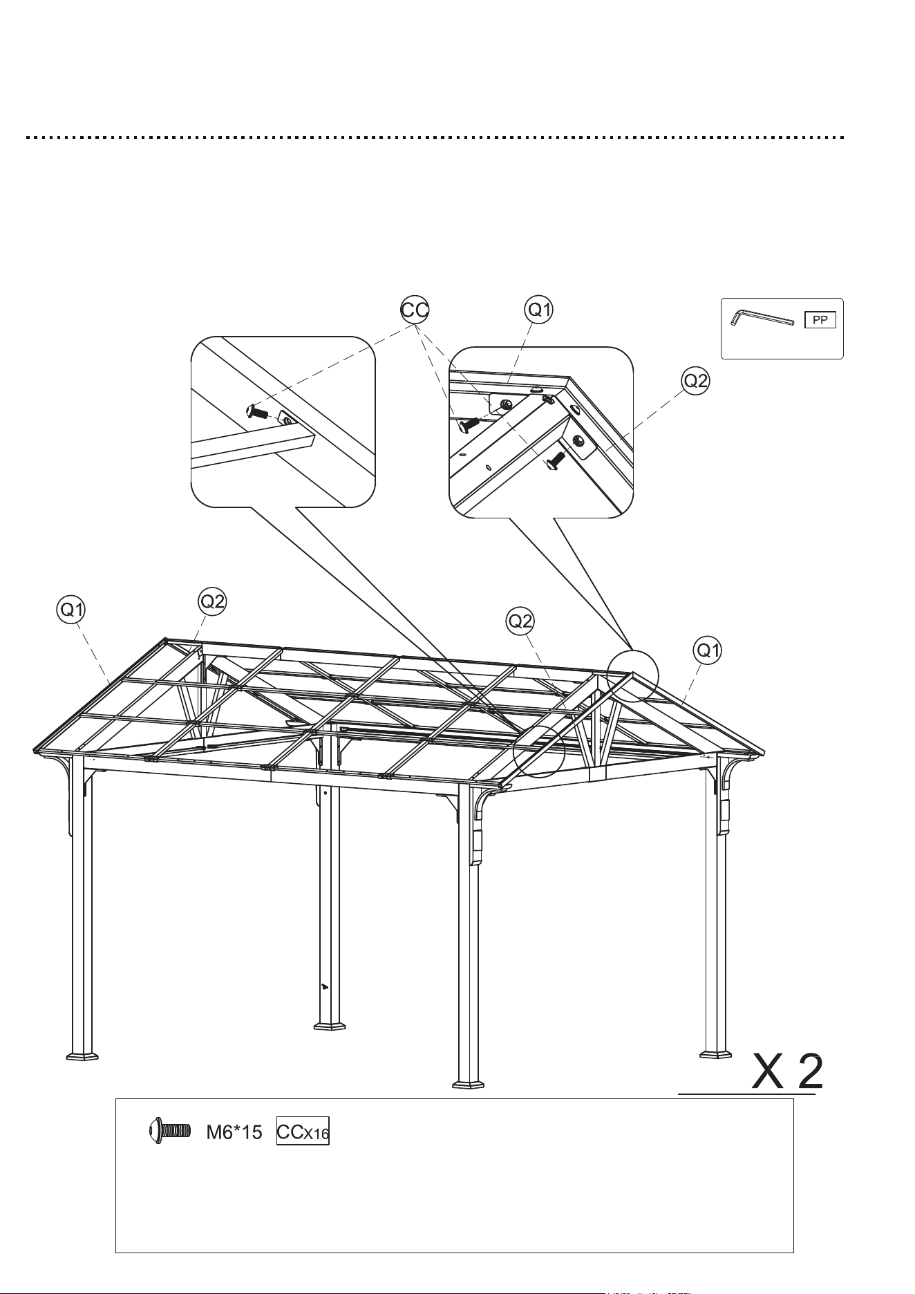
Step 30
1. Attach the Cross beam (Q2) & (Q1) to the Rafter branch unit (P1) &
(P2) & Top beam (M1) with M6*15 bolt with washer (CC).
2. Tighten all bolts by using Allen wrench (PP).
3. Repeat this step for the remaining Cross beam (Q2) & (Q1).
40
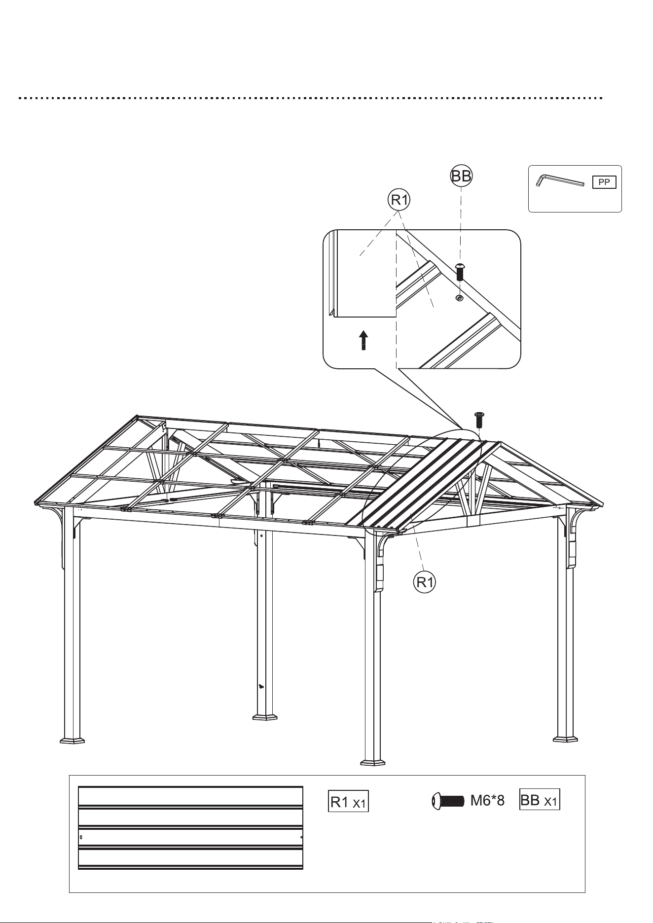
Step 31
1. Attach the Roof panel (R1) to the Roof connector (o) with M6*8 bolt (BB).
2. Tighten all bolts by using Allen wrench (PP).
41
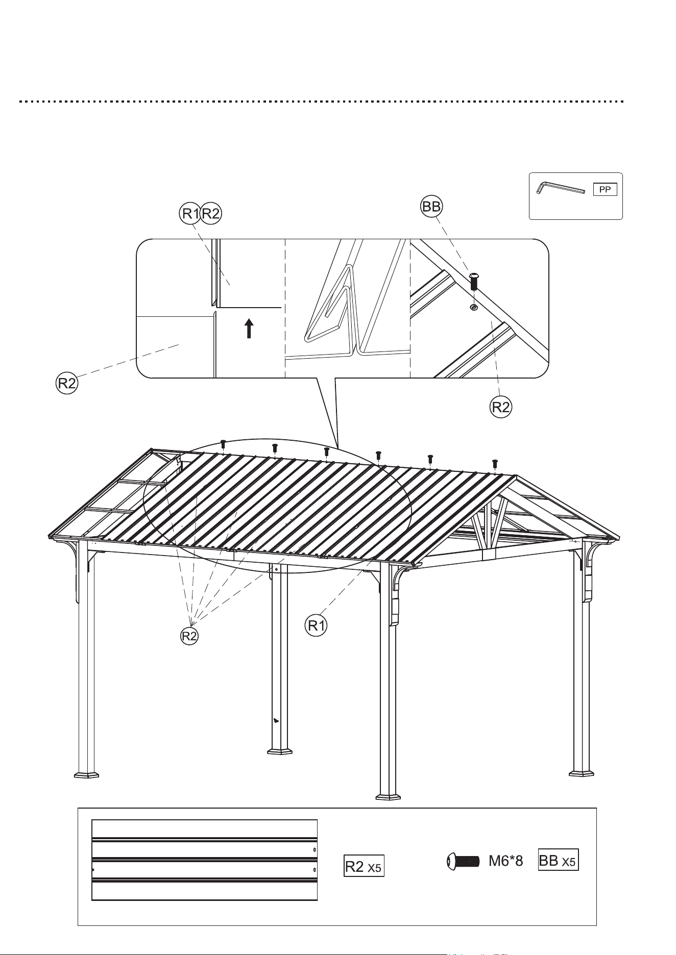
Step 32
1. Insert the Roof panel (R2) into the Roof panel (R1) & (R2) , use the M6*8
bolt (BB) to connect the Roof panel (R2) & Roof connector (O) .
2. Tighten all bolts by using Allen wrench (PP).
42
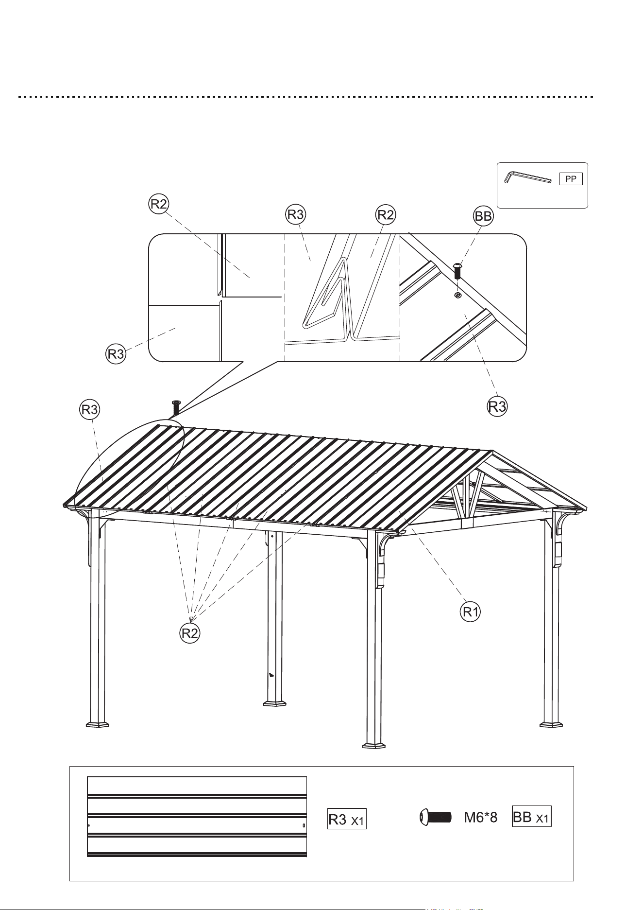
Step 33
1. Insert the Roof panel (R3) into the Roof panel (R2), use M6*8 bolt (BB)
to connect the Roof panel (R3) & Roof connector (O) .
2. Tighten all bolts by using Allen wrench (PP).
43
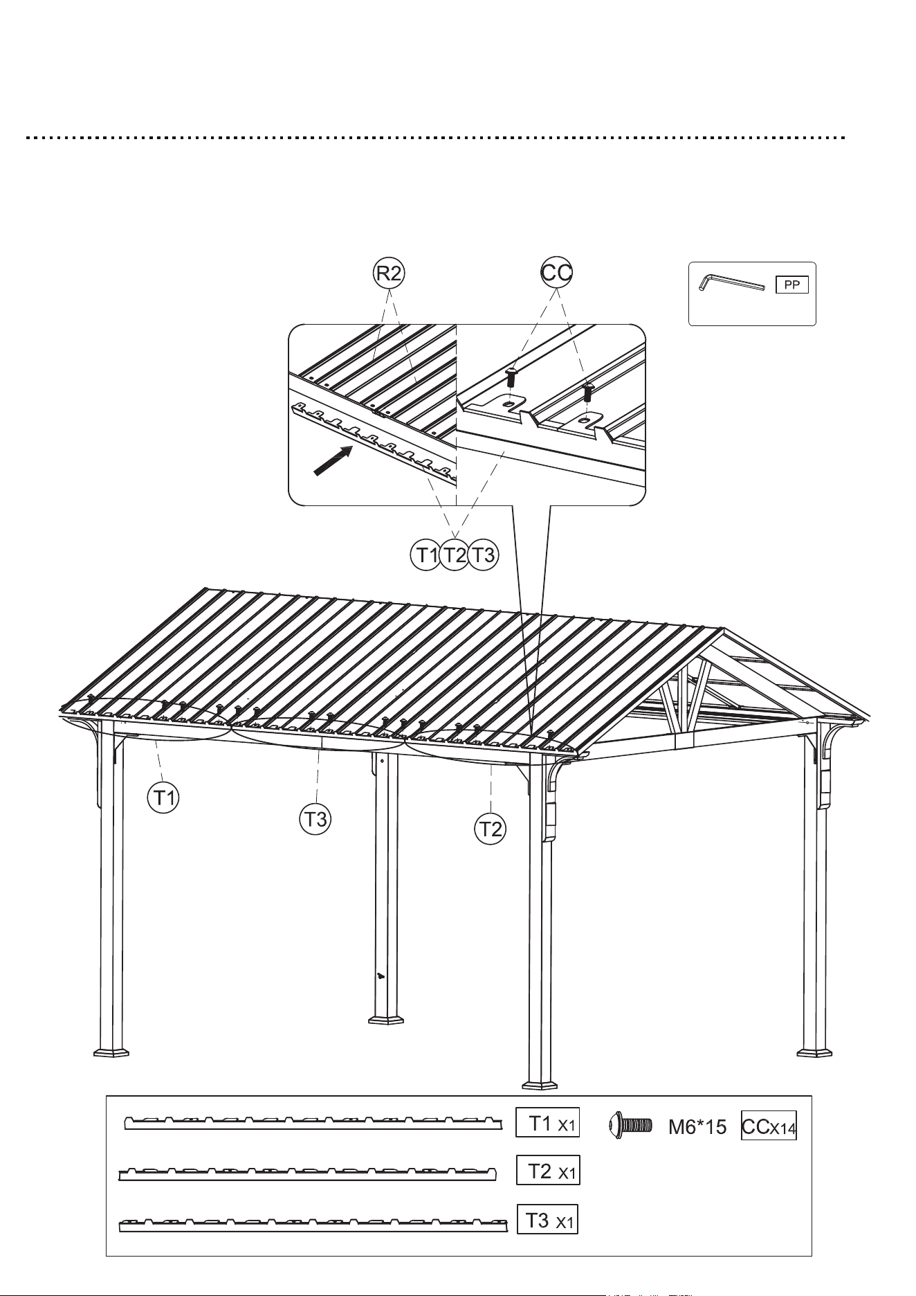
Step 34
1. Attach the Roof edge cap (T1) & (T2) & (T3) through the Roof panel (R1) & (R2) &
(R3) to the Rafter branch unit (P1) & (P2) with M6*15 bolt with washer (CC).
2. Tighten all bolts by using Allen wrench (PP).
44
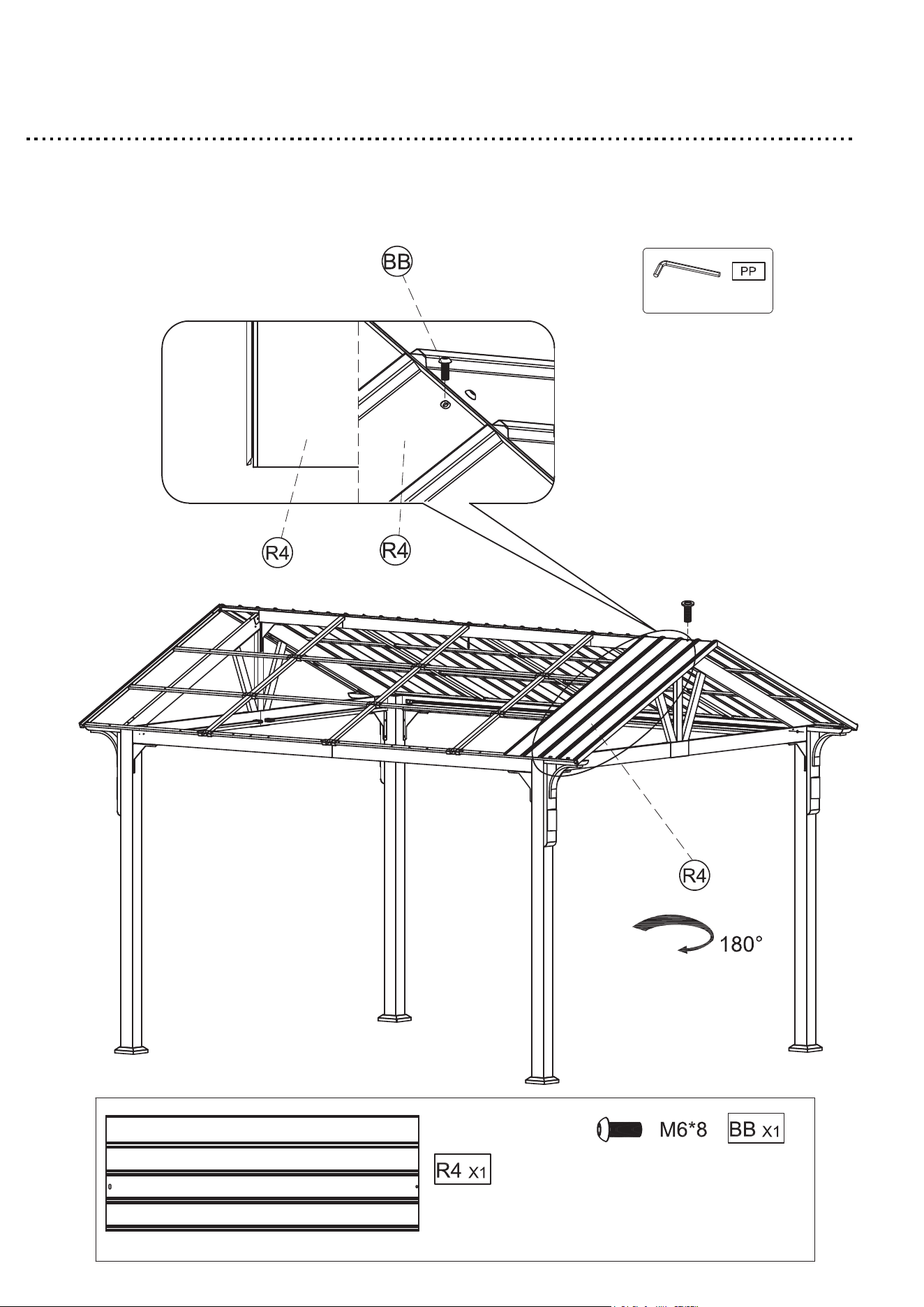
Step 35
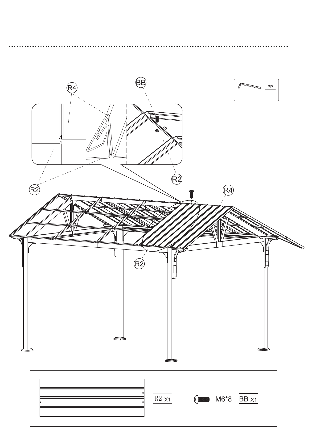
1. Attach the Roof panel (R4) to the Roof connector (O) With M6*8 bolt (BB).
2. Tighten all bolts by using Allen wrench (PP).
45
Step 36
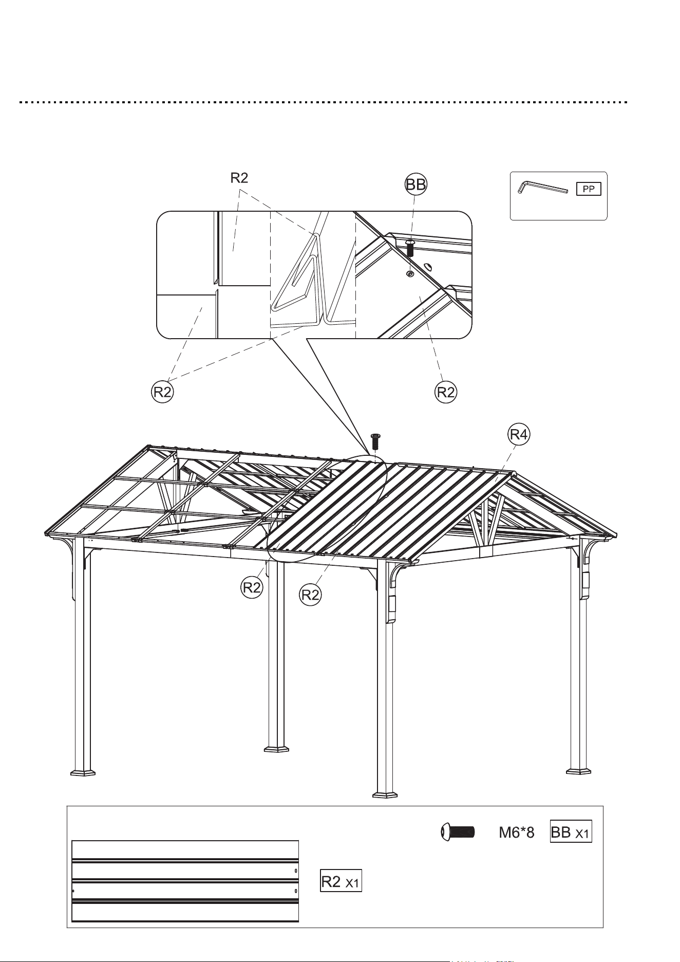
1. Insert the Roof panel (R2) into the Roof panel (R4) , use M6*8 bolt (BB) to
connect the Roof panel (R2) & Roof connector (O) .
2. Tighten all bolts by using Allen wrench (PP).
46
Step 37
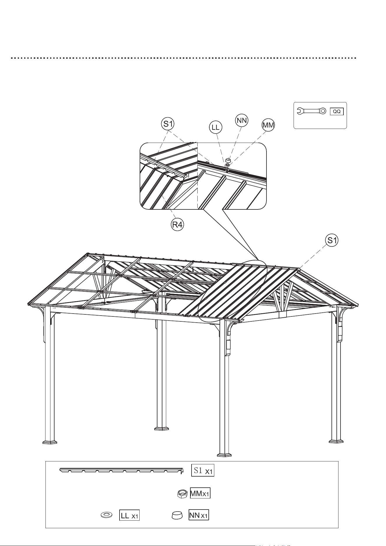
1. Use the washer (LL) & Nut (MM) to fix the Roof top cover (S1).
2. Tighten all bolts by using Hex wrench (QQ).
3. Attach the Nut cap (NN) to the Washer (LL) & Nut (MM).
47
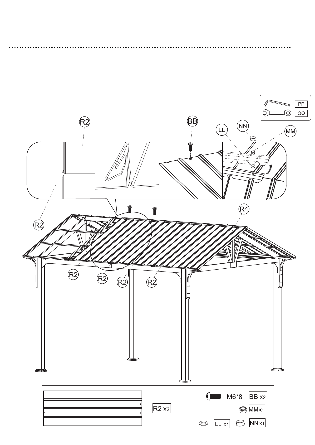
Step 38
1. Insert the Roof panel (R2) into the Roof panel (R2), use the M6*8 bolt
(BB) to connect the Roof panel (R2) to the Roof connector (O).
2. Tighten all bolts by using Allen wrench (PP).
48
Step 39
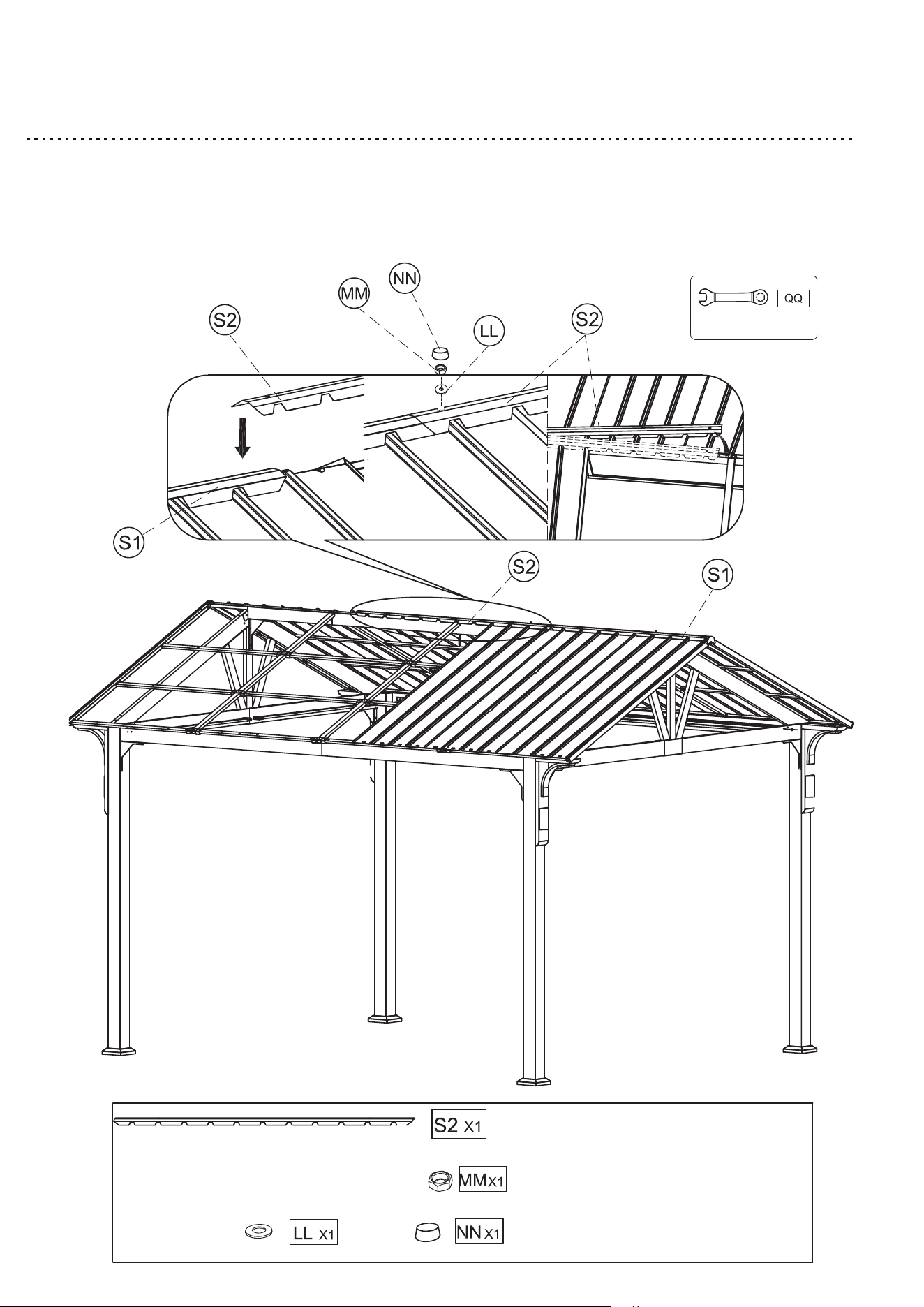
1. Use the washer (LL) & Nut (MM) to fix the Roof top cover (S2).
2. Tighten all bolts by using Hex wrench (QQ).
3. Attach the Nut cap (NN) to the Washer (LL) & Nut (MM).
49
Step 40
1. Insert the Roof panel (R2) into the Roof panel (R2) , use the M6*8 bolt (BB) to
connect the Roof panel (R2) & Roof connector (O) .
2. Tighten bolt by using Allen wrench (PP).
3. Use the washer (LL), Nut (MM) & Nut to fix the Roof top cover.
4. Tighten bolts by using Hex wrench (QQ), then attach the Nut cap
(NN) to the Nut (MM).
50
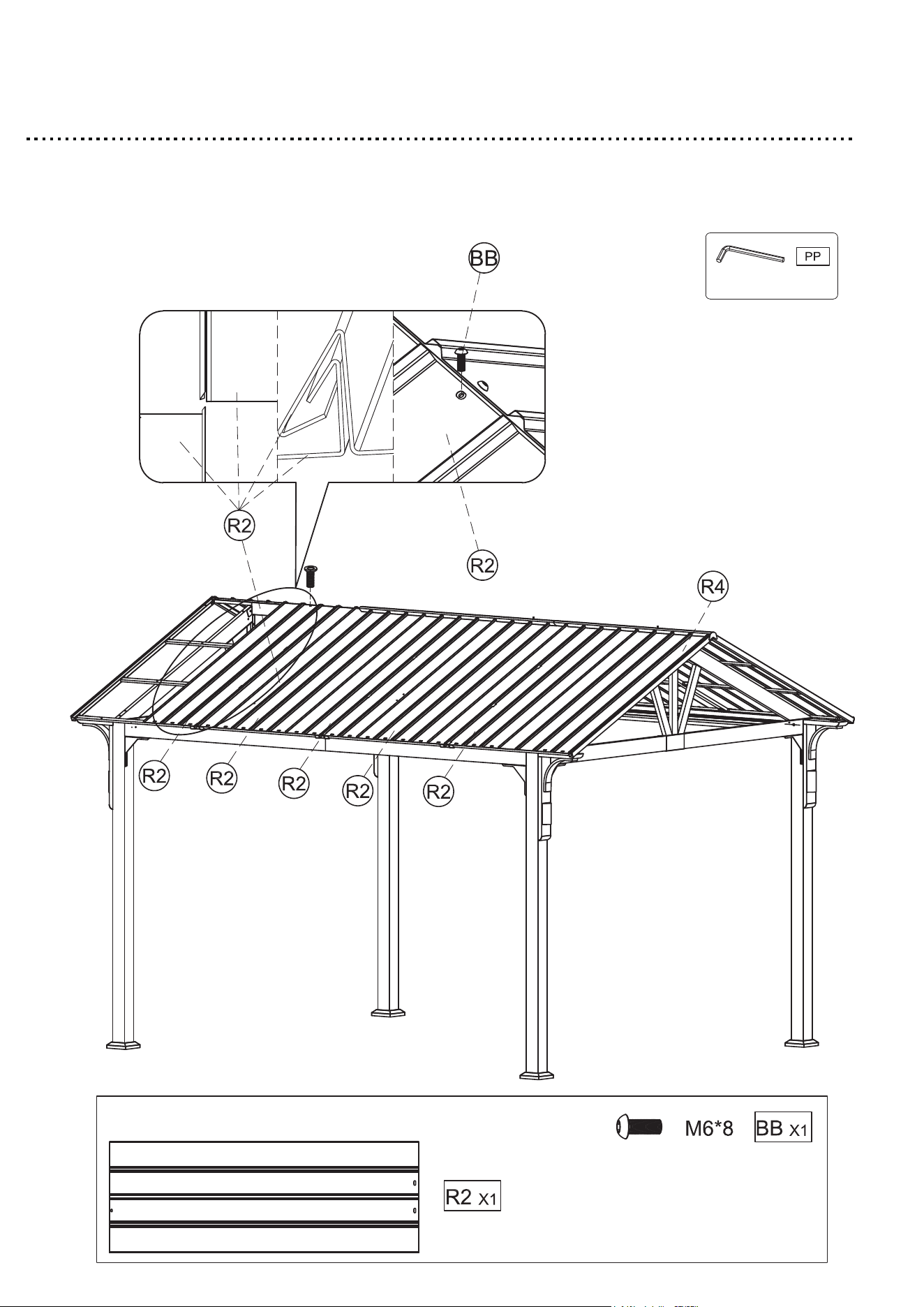
Step 41
1. Insert the Roof panel (R2) into the Roof panel (R2), use the M6*8 bolt
(BB) to connect the Roof panel (R2) & Roof connector (O).
2. Tighten all bolts by using Allen wrench (PP).
51
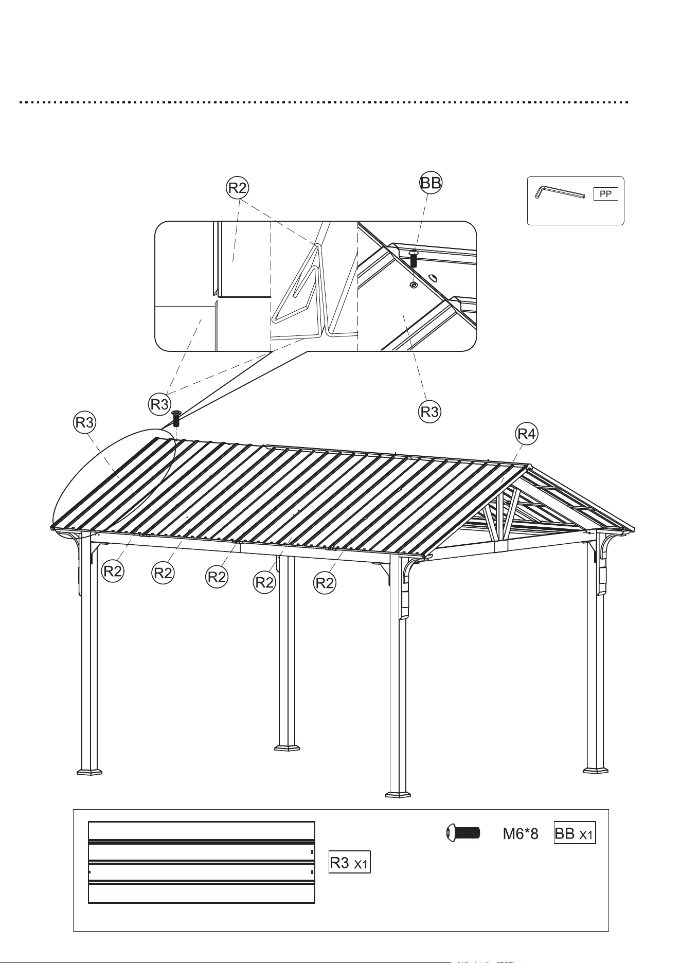
Step 42
1. Insert the Roof panel (R3) into the Roof panel (R2), use the M6*8 bolt
(BB) to connect the Roof panel (R3) & Roof connector (O).
2. Tighten all bolts by using Allen wrench (PP).
52
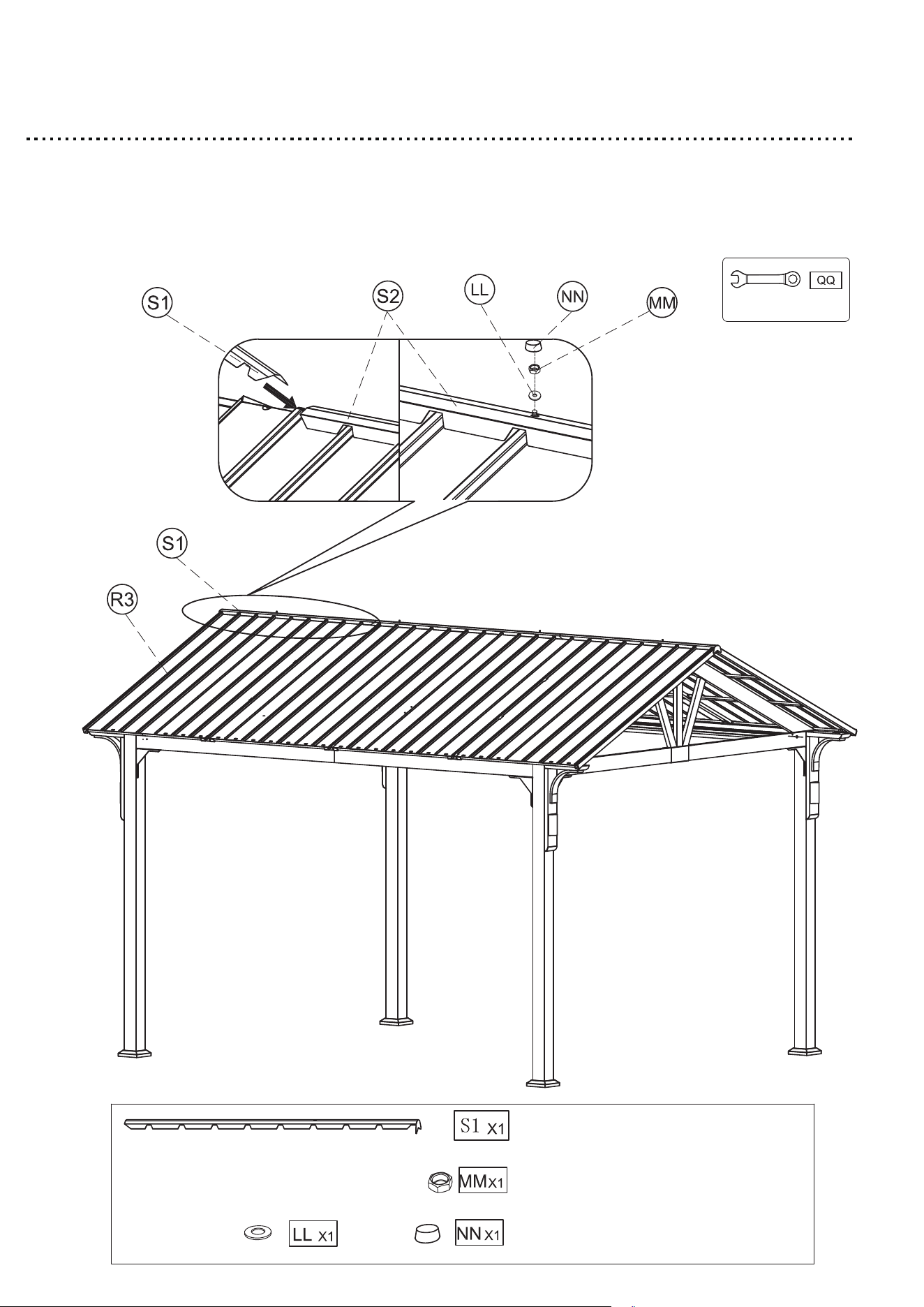
Step 43
1. Use the washer (LL) & Nut (MM) to fix the Roof top cover (S1).
2. Tighten bolts by using Hex wrench (QQ).
3. Attach the Nut cap (NN) to the Washer (LL) & Nut (MM).
53
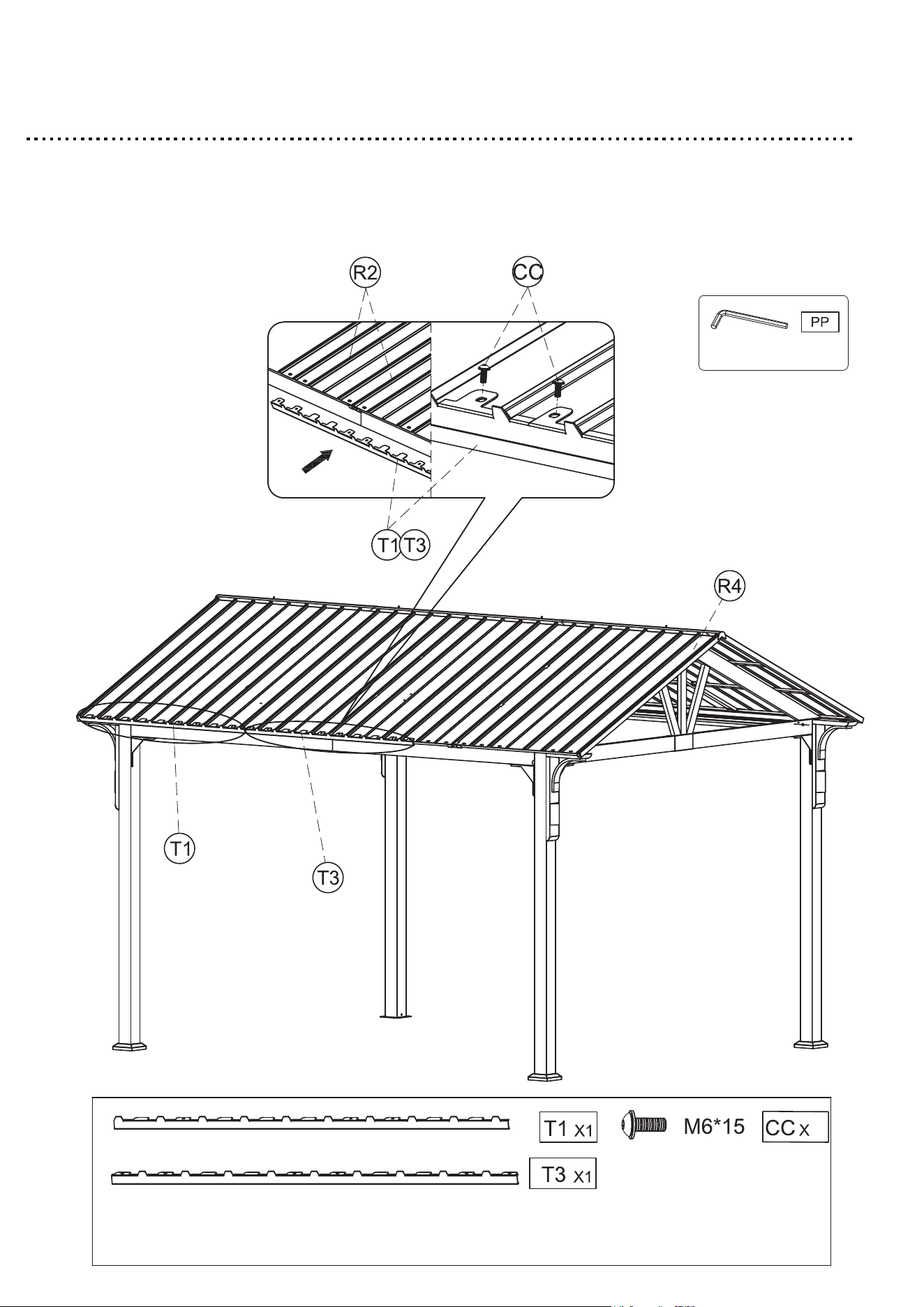
Step 44
1.
Attach the Roof edge cap (T1) & (T3) through the Roof panel (R2) & (R3)
to the Rafter branch unit (P1) & (P2) with M6*15 bolt with washer (CC).
2. Tighten all bolts by using Allen wrench (PP).
10
54
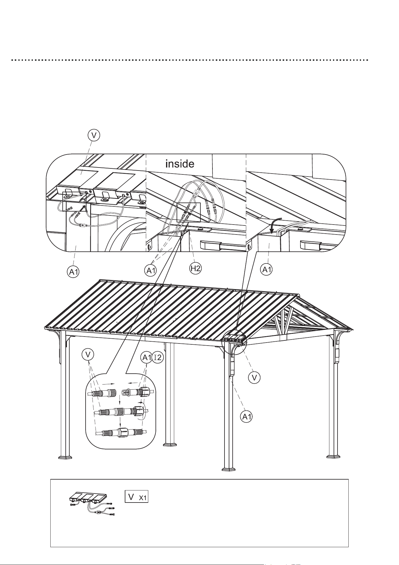
Step 45
1. Attach the Solar panel (V) to the Roof panel.
2. The wires of the switch and the plug are connected to the corresponding
wires .
3. Put the wire into Post leg (A1) to hide it.
55
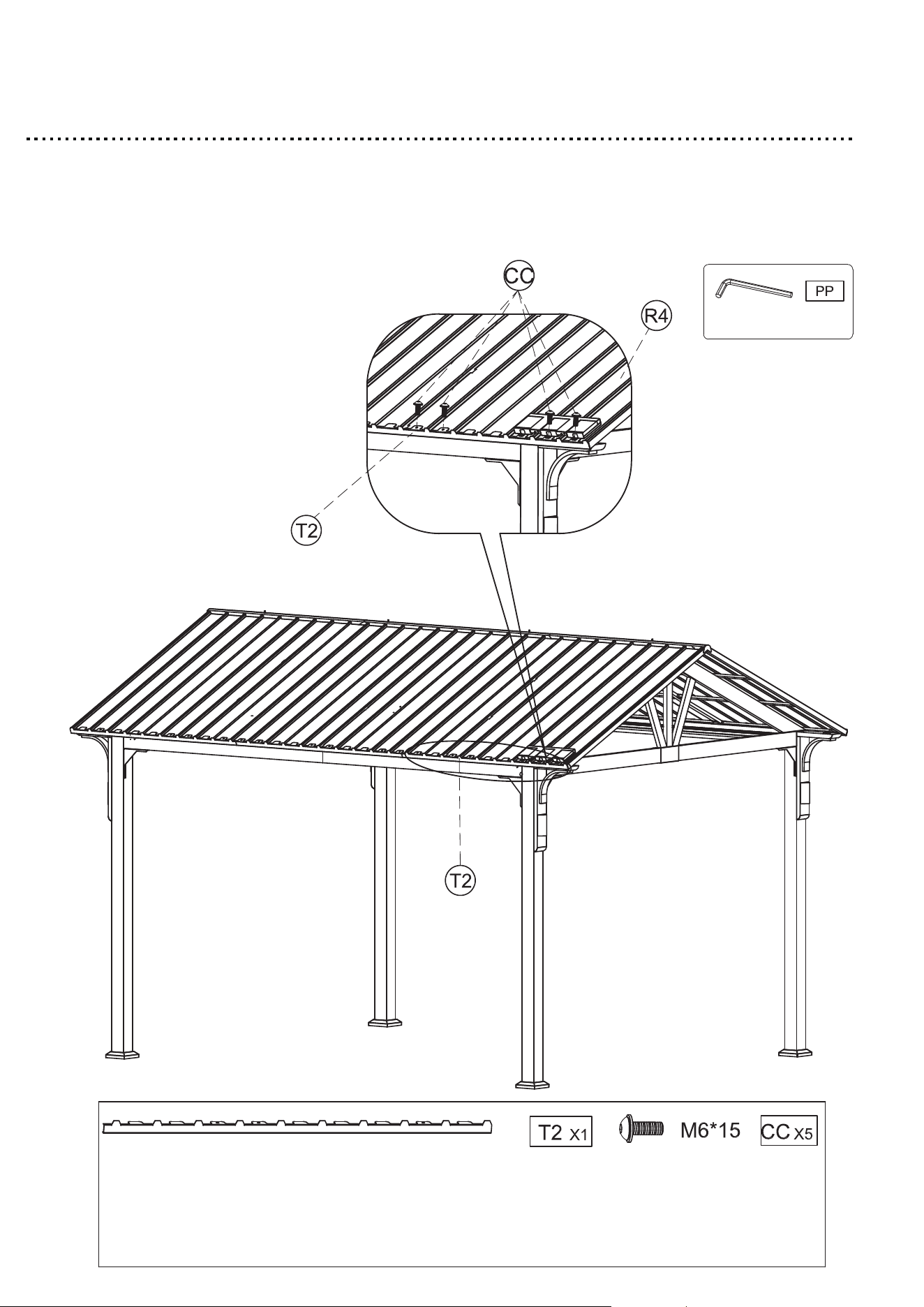
Step 46
1. Attach the Roof edge cap (T2) to the Roof panel (R2) & Roof panel
(R4) with M6*15mm bolt with washer (CC).
2. Tighten all bolts by using Allen wrench (PP).
56
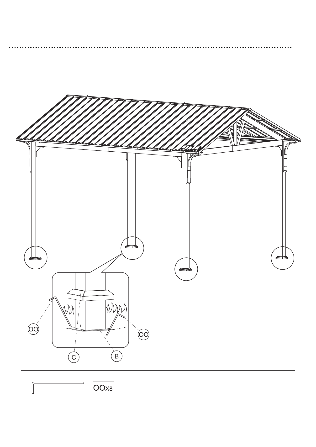
Step 47
1. Insert the Ground stakes (OO) into the holes on the Foot plate (B)
and into the ground.
2. Repeat for all corners.
57
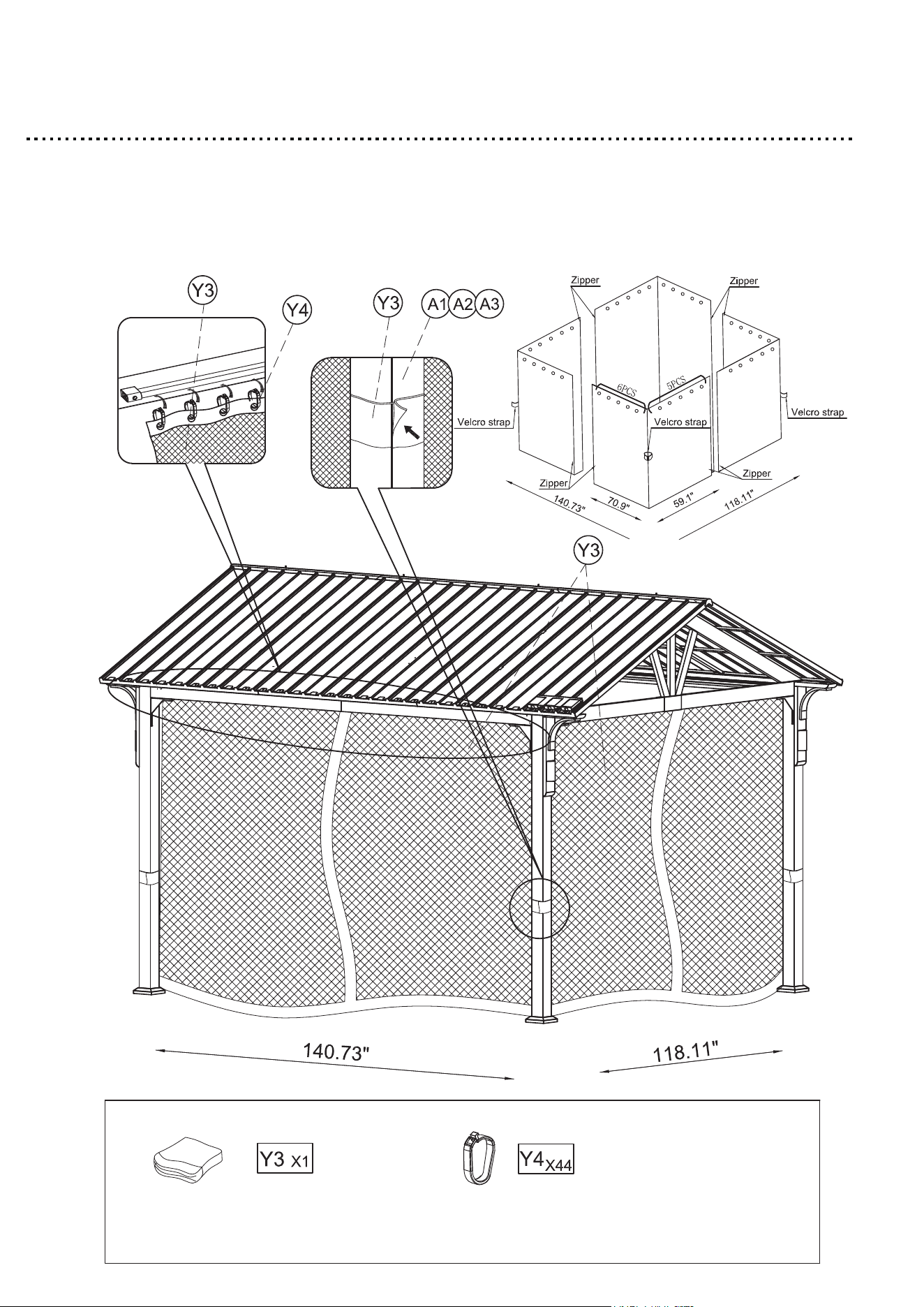
Step 48
1. Hang the Plastic hook (Y4) on the Netting (Y3).
2. Attach the Netting (Y3) to the Long beam & short beam.
3. Velcro strap to the Post leg (A1) & (A2) & (A3).
58
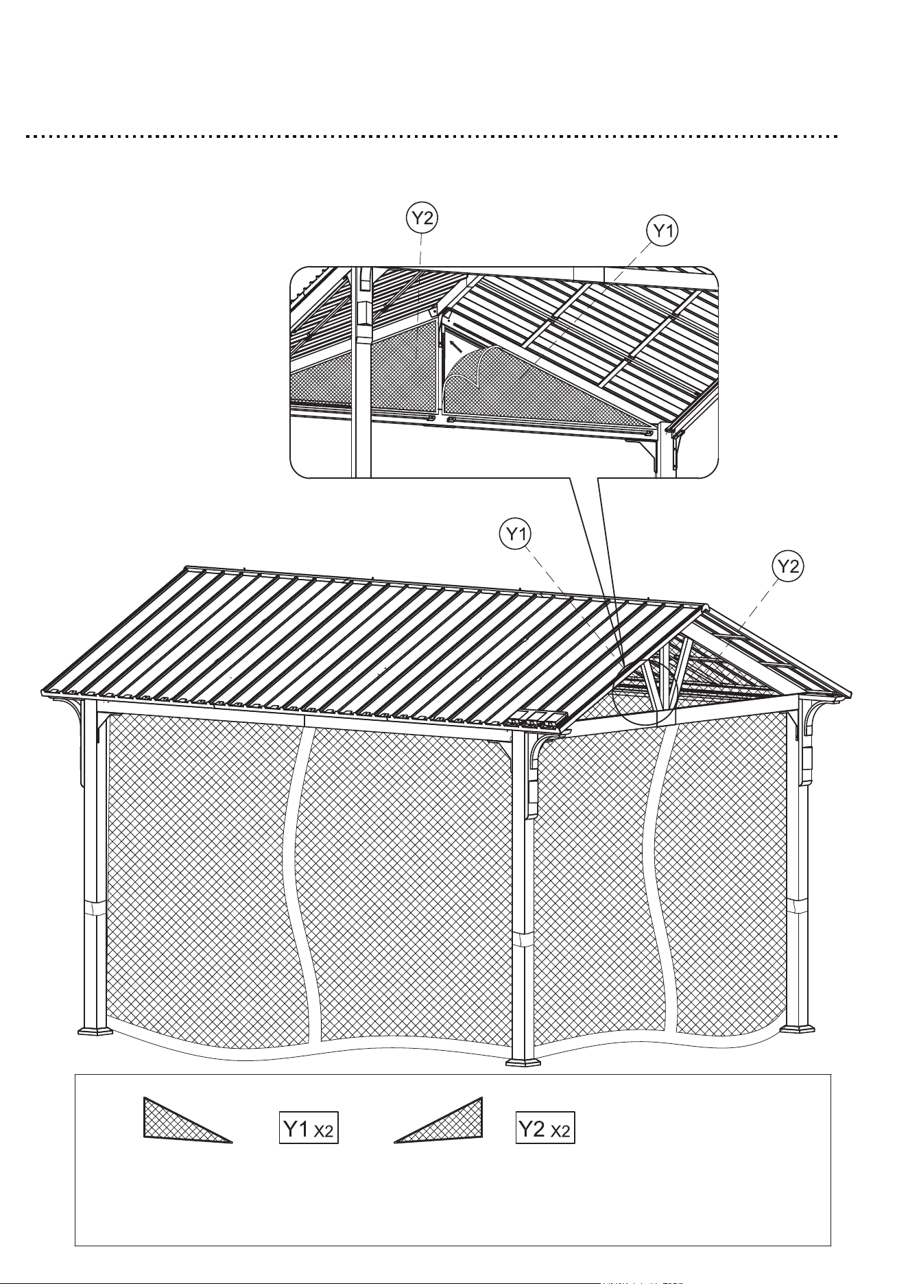
Step 49
1. Attach the Triangular netting (Y1) & (Y2) to the Inclined beam.
59
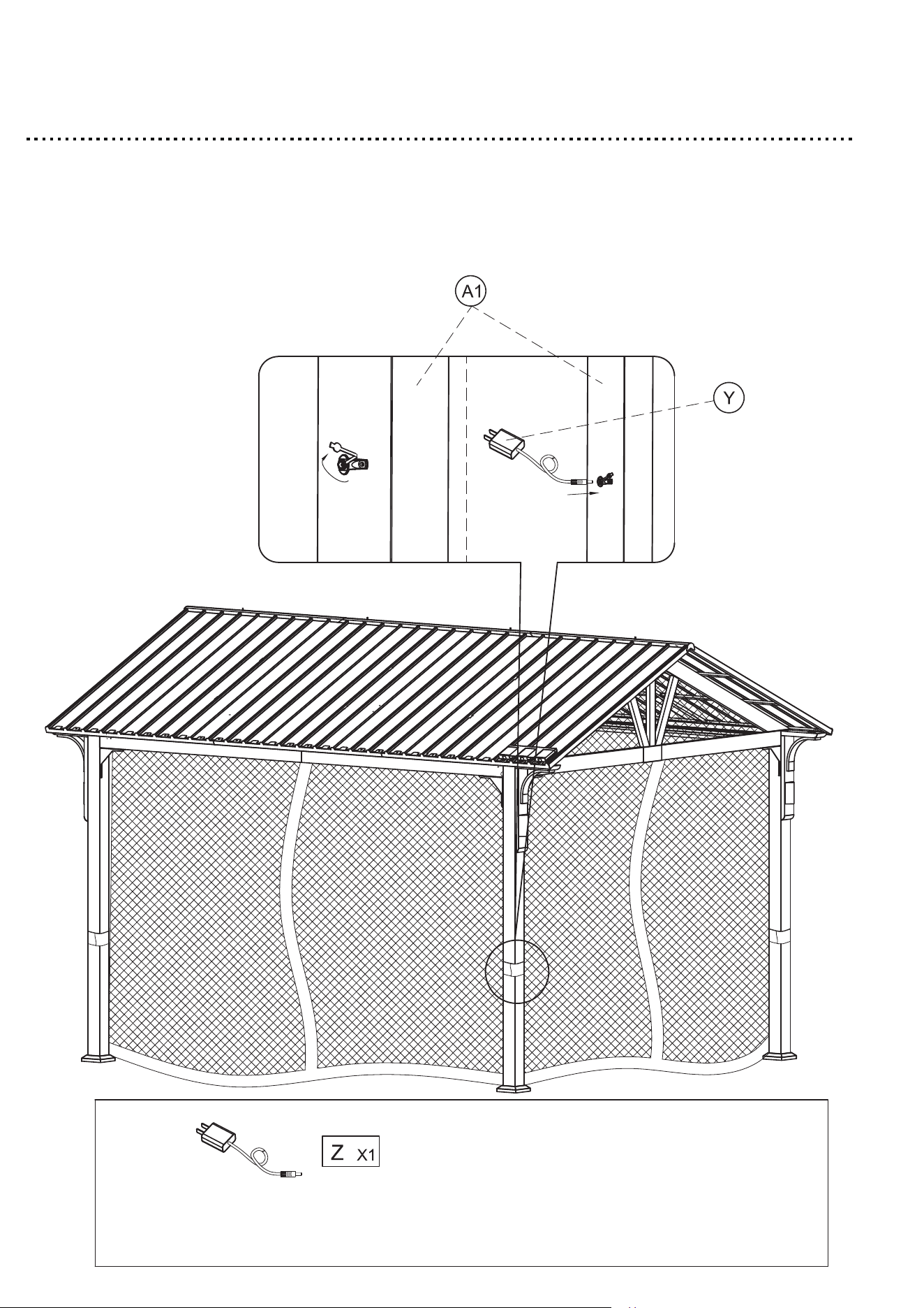
Step 50
1. Insert the Plug (Z) into the Post leg (A1).
2. Ensure that all connections are secure before use.
3. Gazebo assembly is completed.
60