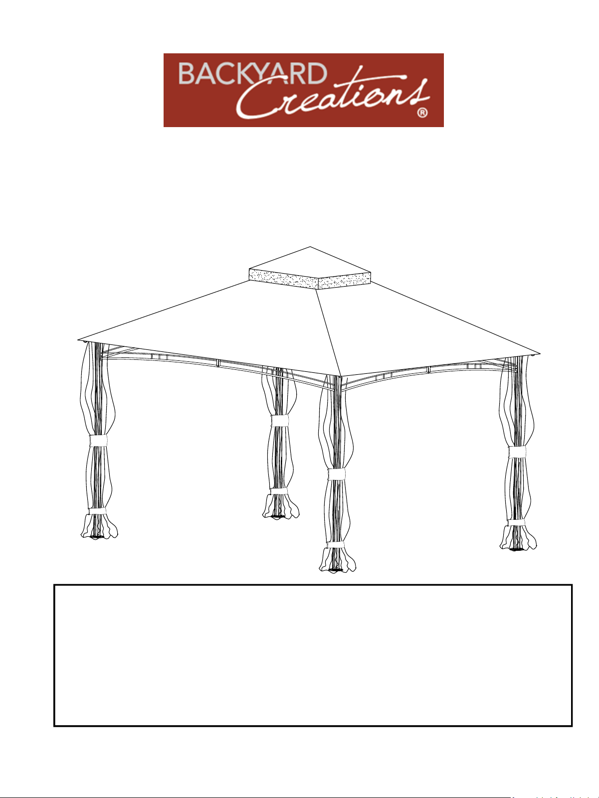
10' x 13' Roof Style Gazebo
Assembly Instruction & User Manual
Menards ®SKU: 2723022
This instruction manual contains important information necessary for the
proper assembly and safe use of the structure.
Read and follow all warnings and instructions before assembling.
Make sure all parts are present. If you have any questions, please call our
Customer Service: (888)-380-7953. For further assistance, please write to
us at Email: [email protected].
Table of Contents
Page 1 of 20
Warnings......................……..…..........................................2
Exploded View……………………………….........................3
Parts Identification………………………...............…............4
Preassembly Step……………………..…..…................. 5-19
Limited Warranty........………………..................................20
Note: Before beginning assembly of product, make
sure all parts are present. Compare parts with
package content list and hardware contents. If any
part is missing or damaged, DO NOT attempt to
assemble the unit. Contact customer service
parts@uriahproducts.com
for replacement parts.

1. Keep children and pets away from assembly area during assembly.
2. The product should be placed on flat horizontal ground.
3. The assembled gazebo should be located at least 6 feet from any obstruction such as overhanging
branches, laundry lines, or electrical wires.
4. Some parts may contain sharp edges. Wear protective gloves if necessary.
5. Must ensure all connectors and poles are firmly secured in position after assembly to avoid
collapsing or damage or injury.
6. Must check all nuts and bolts periodically for tightness and tighten them again if needed.
7. Never leave children unattended when they are using or are around this product.
8. Do not use ladder leaning against the gazebo or climbing onto the roof.
9. Do not hang any weights on the roof frame.
10. Do not climb on top of the gazebo to avoid any injury.
11. This gazebo is intended for sunshade purposes only and is not designed to withstand hard
weather, including high winds, rain, and snow, especially under extreme weather either.
12. Must remove accumulated water or snow on the roof immediately to avoid damage.
13. Never barbecue under this gazebo or use lanterns that contain naked flames.
14. If the product will not be used for a long period (e.g. winter time), it should be stored in a clean,
dry environment.
15. WARNING: Please take down the gazebo during strong wind. The manufacturer or retailer is not
liable for any loss of the product or other items due to the failure to take down the gazebo during
strong wind.
16. Do not use or enter the gazebo if there is visible movement of product supports, any creaks or
broken parts, or any damaged locations.
WARNING: Warranty does not cover damage due to extreme weather conditions
WARNING: This gazebo is not a permanent structure; it is intended solely for providing shade and
privacy and should only be used in normal weather. You must fully disassemble the entire unit
before any severe weather hits, such as thunderstorms, snow, sleet, hurricanes, or heavy wind and
rain.
WARNING: Keep any flame or heat source at a distance from the tent fabric.
WARNING: Always set up the unit on level ground, and use tie-down cords and ground stakes for
installation. Do not anchor it permanently to a wooden deck or concrete surface.
Warnings
Page 2 of 20
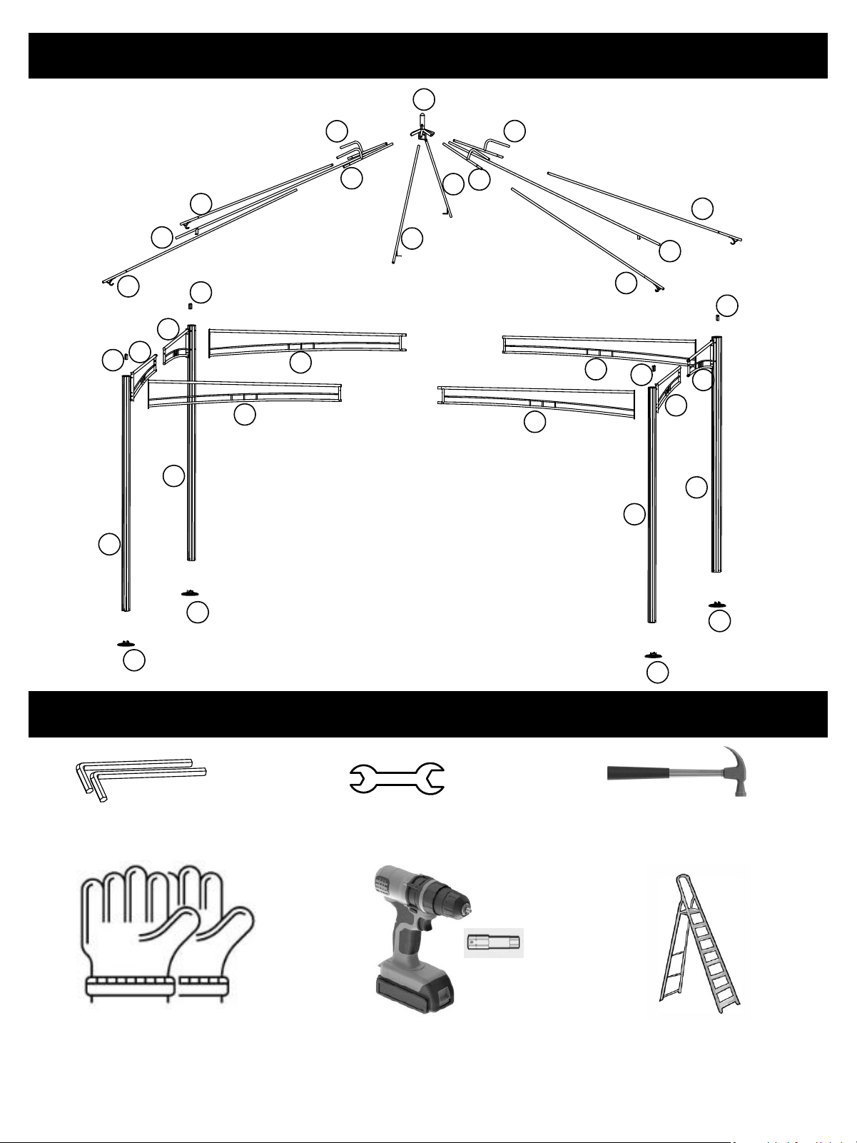
Exploded View
Page 3 of 20
Preassembly
Ladder
(Not Included)
Glove
(Not Included)
Electric Drill
(Not Included)
Allen wrench
(Included)
Hex wrench
(Included)
Hammer
(Not Included)
I
F1
F1
F1
F1
F2
F2
F2
F2
G
G
H
H
K
K
K
K
D
D
E
E
C
C
B
B
A
A
A
A
J
J
J
J
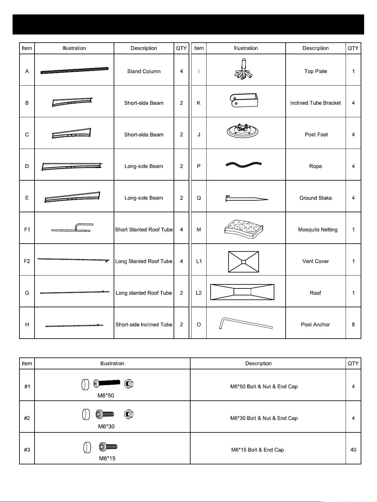
Parts Identification
Page 4 of 20
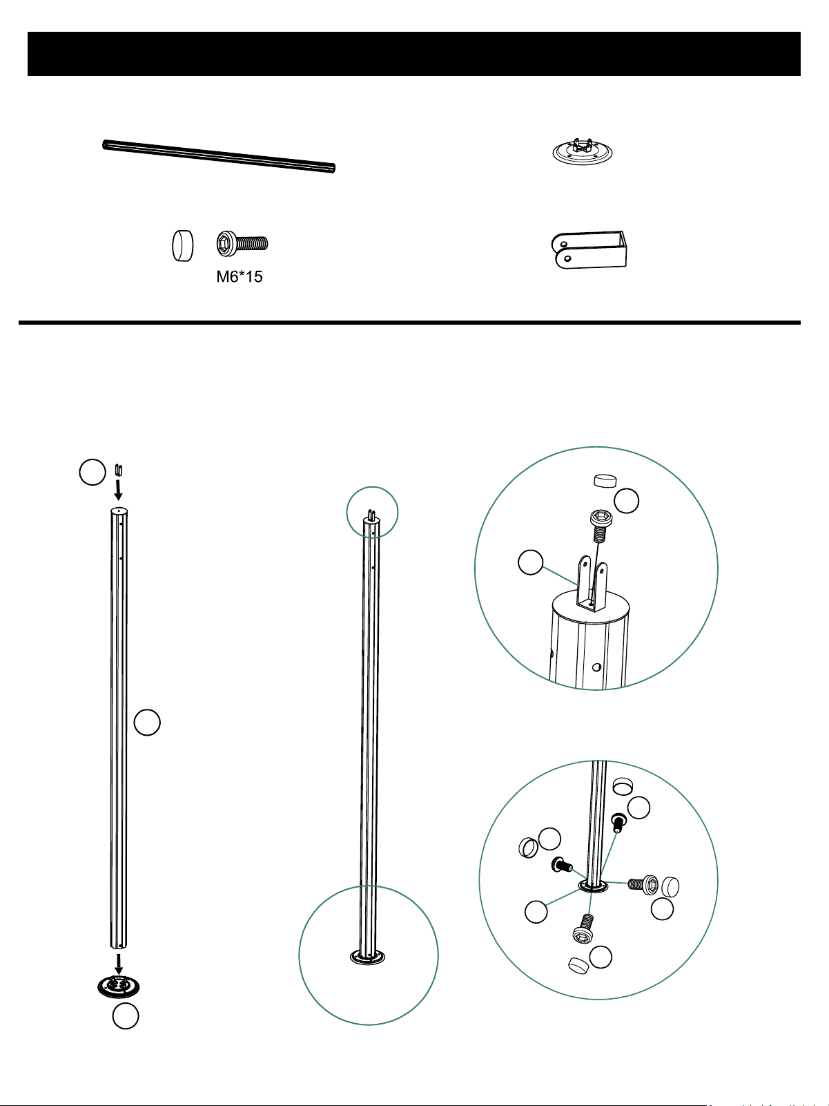
Assembly Instruction
Step 1:
Page 5 of 20
Part A:Stand Column 4pcs
Part J:Post Foot 4pcs
Part K:Inclined Tube Bracket 4pcs
Part #3:M6*15 Bolt & End Cap 20pcs
NOTE:
Use Part #3 (M6*15 Bolt & End Cap) to connect Part A (Stand Column) and Part K (Inclined
Tube Bracket); do not tighten Part #3 at this stage.
Use Part #3 (M6*15 Bolt & End Cap) to fasten Part A (Stand Column) and Part J (Post Foot)
together.
K
A
J
K
#3
#3
#3
#3
#3
J
Assembly Instruction
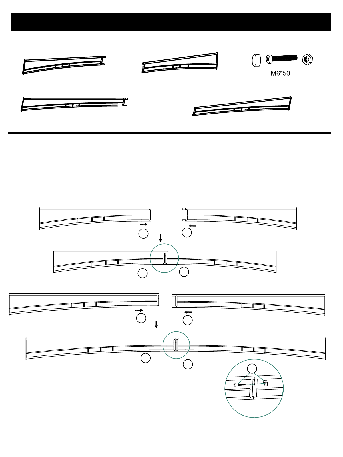
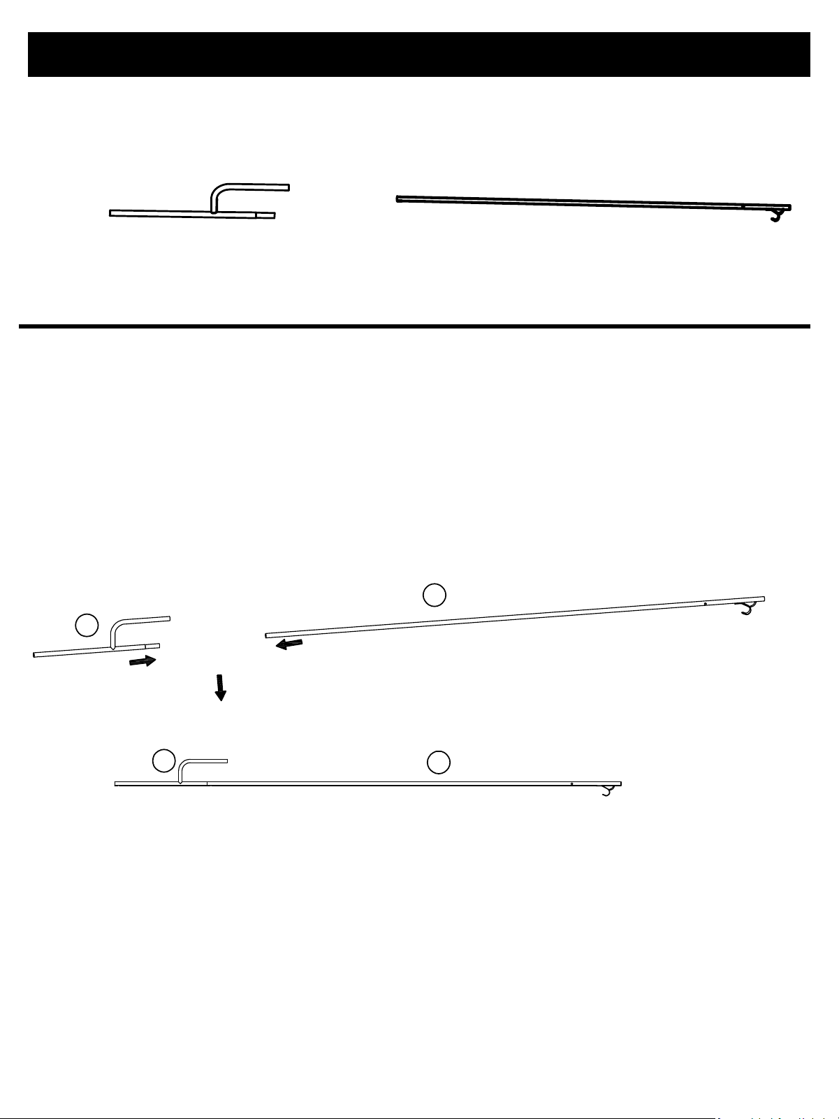
Step 2:
Page 6 of 20
Part B:Short-side Beam 2pcs Part C:Short-side Beam 2pcs
Part D:Long-side Beam 2pcs Part E:Long-side Beam 2pcs
NOTE:
Connect Part B (Short-side Beam ) and Part C(Short-side Beam ) using Part #1 (
M6*50 Bolt & Nut & End Cap ).
Connect Part E(Long-side Beam) and Part D(Long-side Beam) using Part #1(M6*50
Bolt & Nut & End Cap ).
Part #1:M6*50 Bolt &
Nut & End Cap 4pcs
E
B
B
D
C
C
E
D
#1
Assembly Instruction
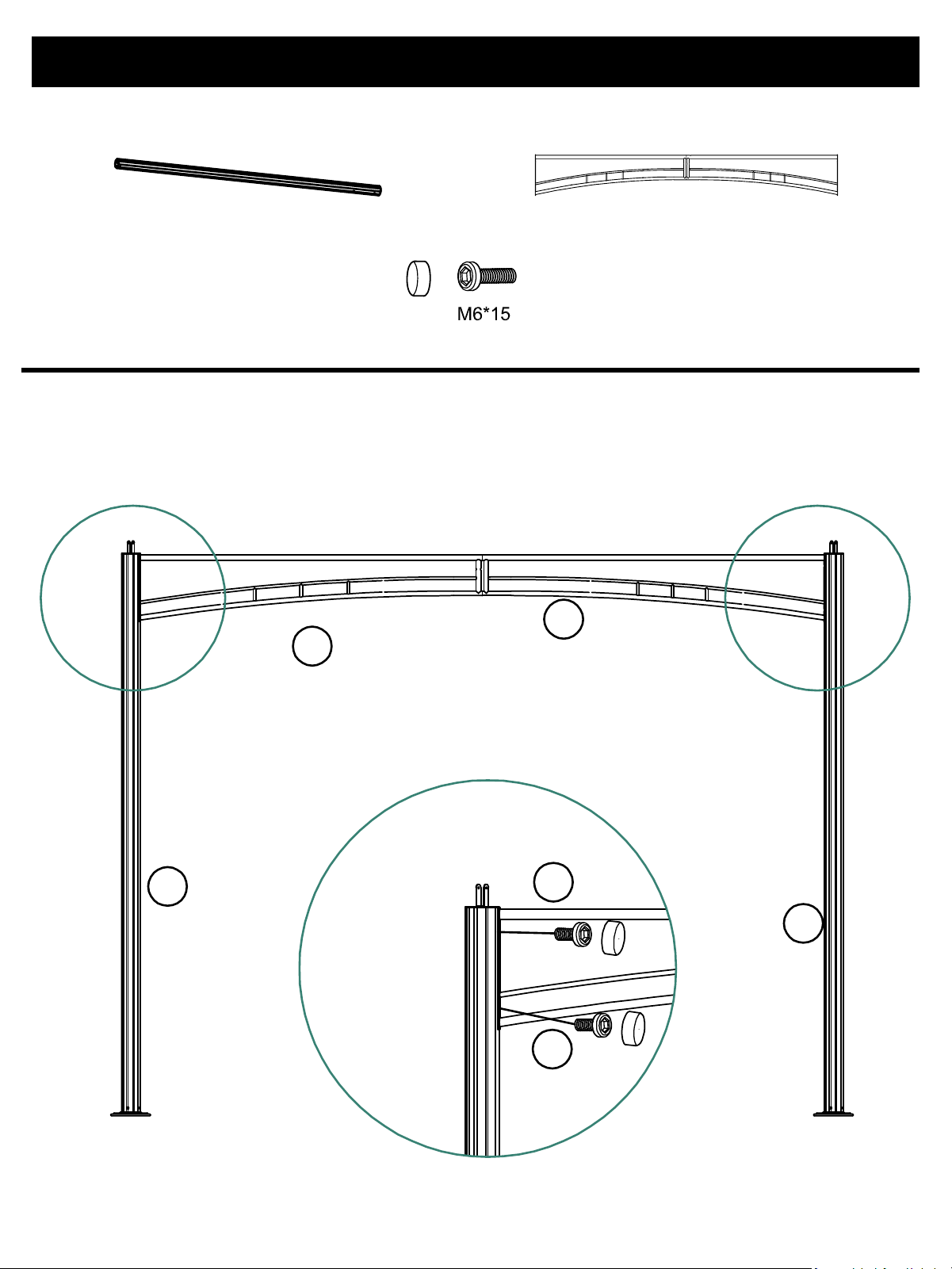
Step 3:
Page 7 of 20
Part A:Stand Column 2pcs
Part #3:M6*15 Bolt & End Cap
Part B+C:Short-side Beam 1pc
4pcs
NOTE:
Use Bolt #3 (M6*15 Bolt & End Cap) to connect Part A (Stand Column) with the
assembled Part B and Part C from Step 2.
A
A
C
B
#3
#3
Assembly Instruction
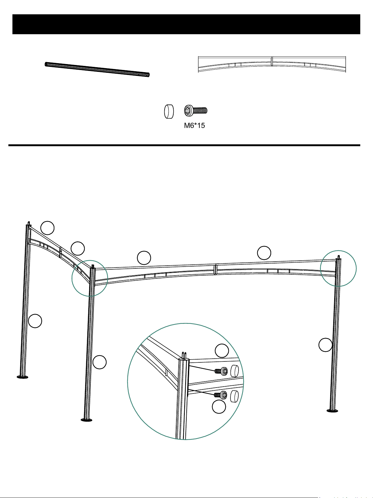
Step 4:
Page 8 of 20
Part A:Stand Column 1pc
Part #3:M6*15 Bolt & End Cap
Part D+E:Short-side Beam 1pc
4pcs
NOTE:
Use Bolt #3 (M6*15 Bolt & End Cap) to connect Part A (Stand Column) with the
assembled Part D and Part E from Step 2.
Part #B and Part #E must be installed adjacent to each other; Failure to do so will
result in the inability to assemble the roof subsequently.
A
A
A
C
B
E
D
#3
#3
Assembly Instruction
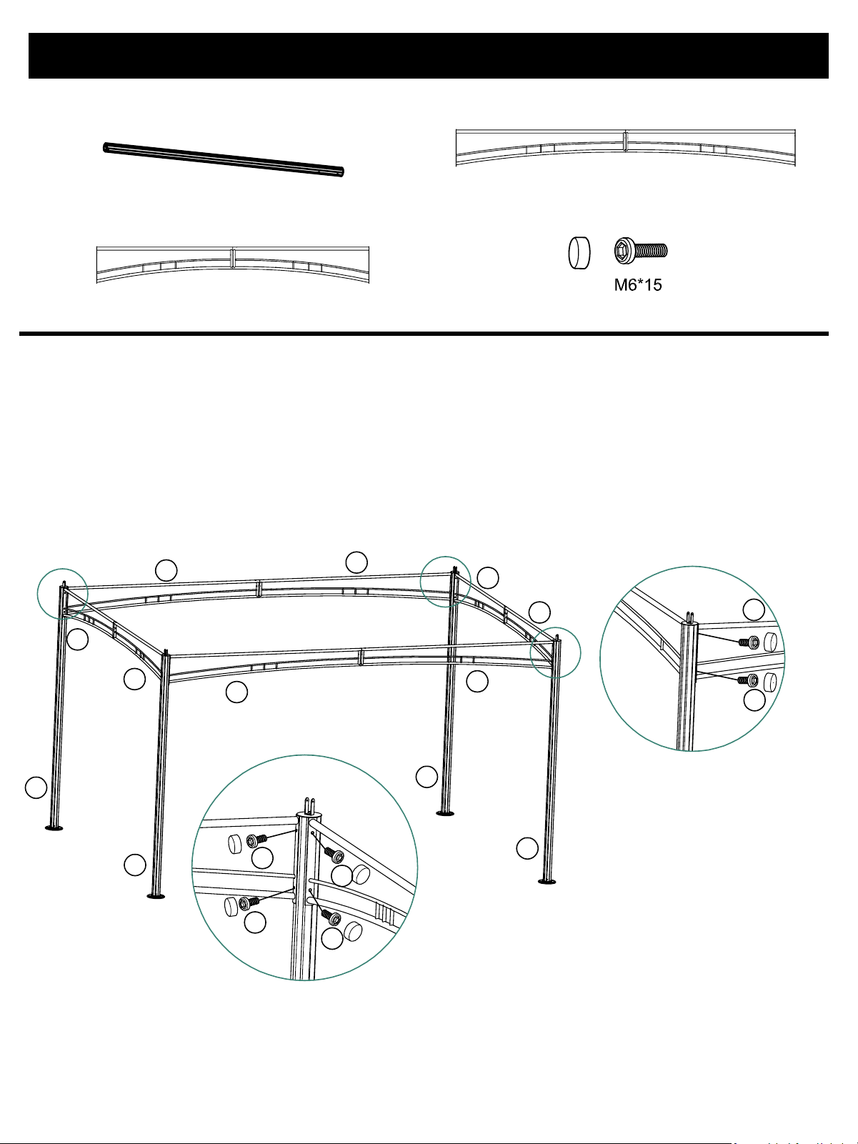
Step 5:
Page 9 of 20
Part A:Stand Column 1pc
Part D+E:Short-side Beam 1pc
Part #3:M6*15 Bolt & End Cap 8pcs
NOTE:
Connect the remaining Part A (Stand Column) with the assembled Part B+C and Part D+E
from Step 2 using #3 (M6*15 Bolt & End Cap) .
Part #B must be adjacent to Part #E, and Part #C must be adjacent to Part #D during
installation. Failure to do so will result in the inability to assemble the roof subsequently.
Part B+C:Short-side Beam 1pc
A
E
D
C
B
#3
#3
#3
#3
#3
#3
A
A
A
E
D
B
C
Assembly Instruction
Step 6:
Page 10 of 20
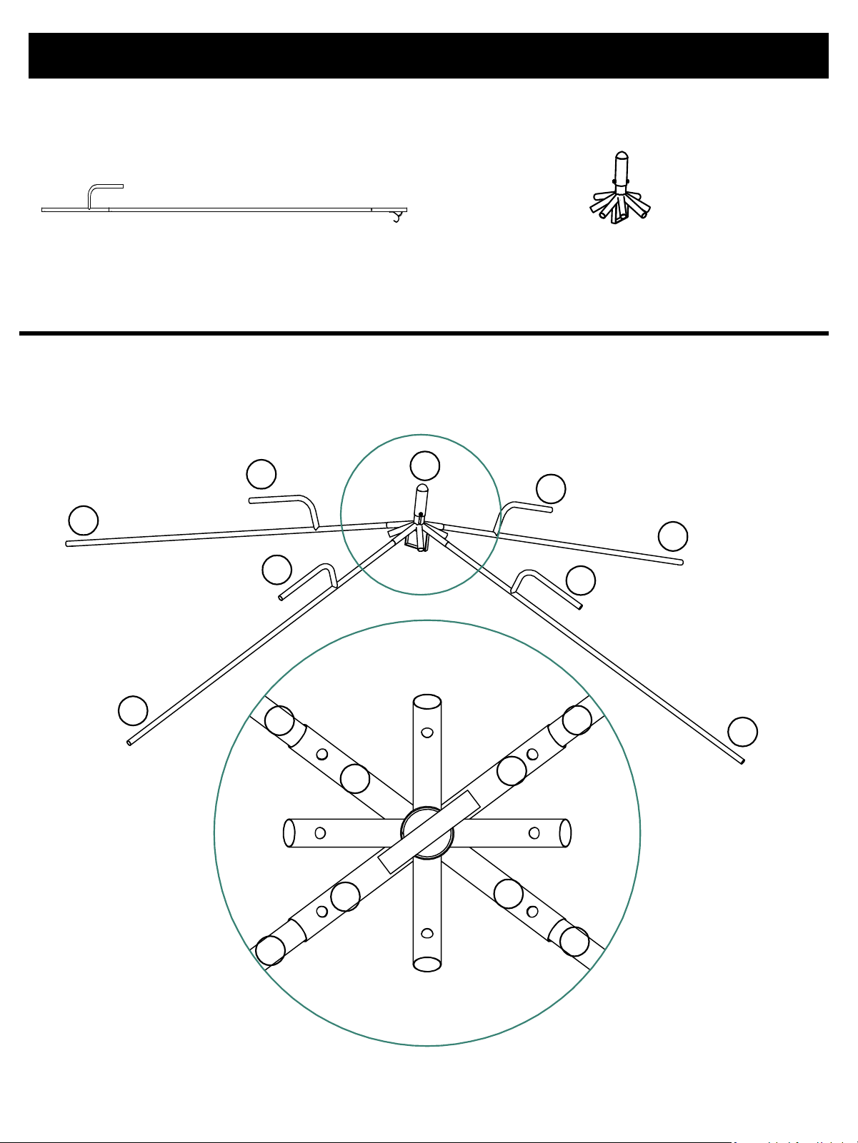
Part F1:Short Slanted Roof Tube 4 pcs Part F2:Long Slanted Roof Tube 4 pcs
NOTE:
Connect Part F1 (Short Slanted Roof Tube)and Part F2 (Long Slanted Roof Tube)
together with a spring clip.
F2
F2
F1
F1
Assembly Instruction
Step 7:
Page 11 of 20
Part F1/F2:Slanted Roof Tube 4 pcs
NOTE:
Connect the beveled edge of Part I (Top Plate) with the 4 pcs of assembled Part F1 and
Part I:Top Plate
Part F2 from Step 6 using a spring clip.
F1
F1
F1
F1
I
F2
F2
F2
F2
F1
F1
F1
F1
F1
F1
F1
F1
Assembly Instruction
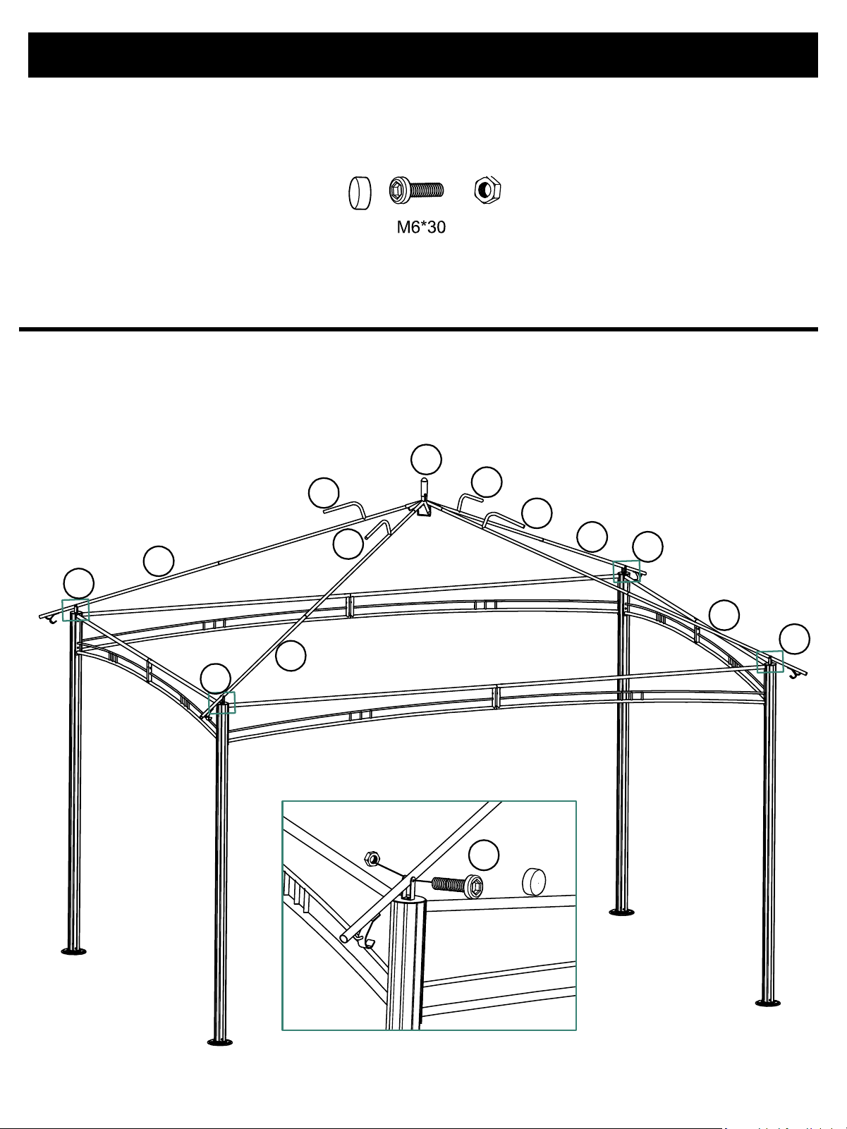
Step 8:
Page 12 of 20
Part #2:M6*30 Bolt & Nut & End Cap 4pcs
NOTE:
After confirming the connection orientation between Part K (Inclined Tube Bracket) and
Part F2 (Long Slanted Roof Tube), first fasten the nut that secures Part K to Part A(Stand
Column) , then install the bushing. Following this, connect Part F2 to Part K.
F1
F1
F1
F1
F2
F2
F2
F2
I
K
K
K
K
#2
Assembly Instruction
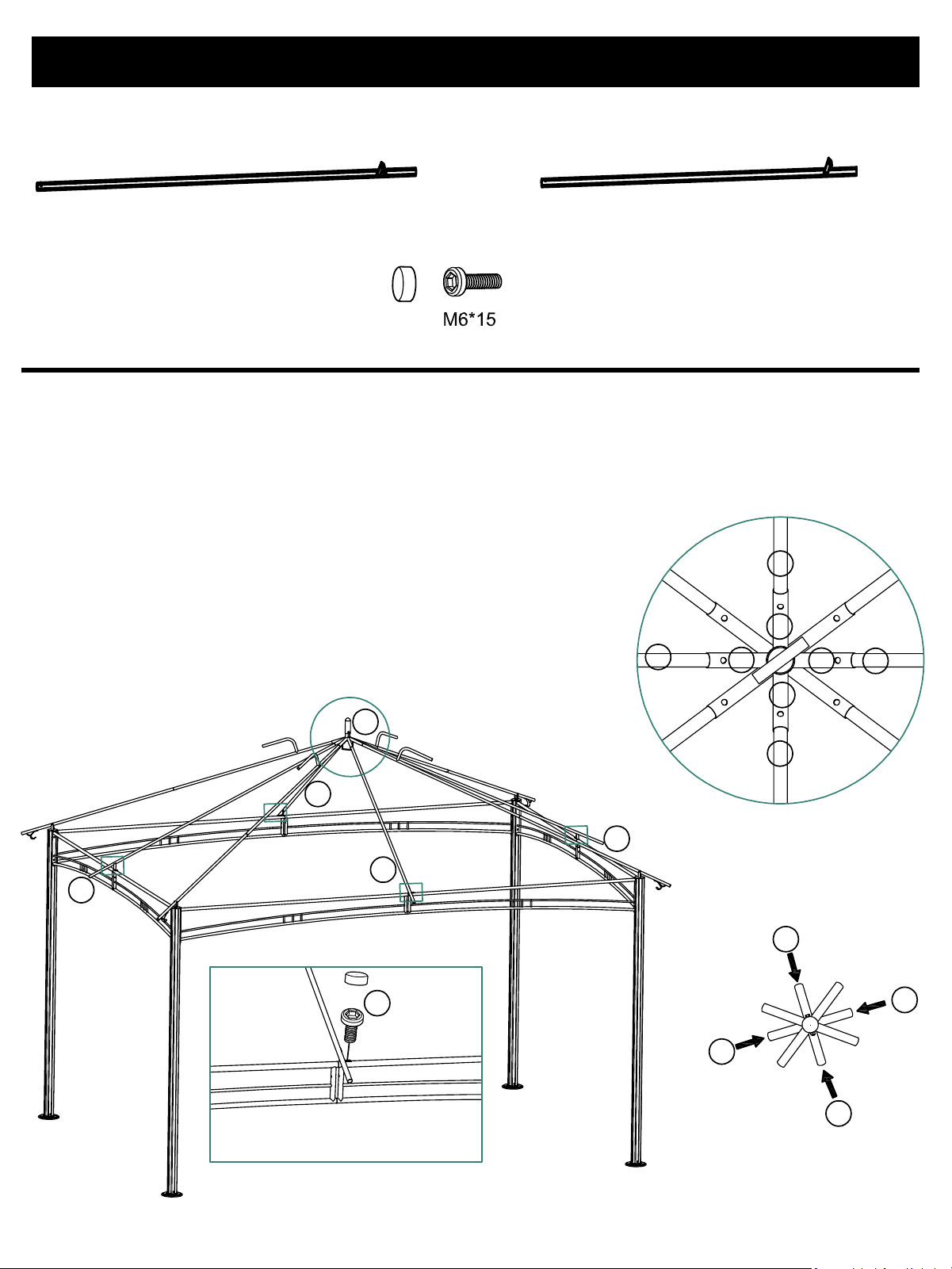
Step 9:
Page 13 of 20
NOTE:
Connect Part H (Short-side Inclined Tube) and Part G (Long-side Inclined Tube) to Part I
(Top Plate) using a spring clip. Then connect Part H and Part D (Long-side Beam)with
Part #3 (M6*15 Bolt & End Cap) , and connect Part G and Part B (Short-side Beam)with
Part #3.
Part #3:M6*15 Bolt & End Cap 4pcs
Part G:Long-side Inclined Tube 2pcs
Part H:Short-side Inclined Tube 2pcs
I
H
H
G
G
H
H
G
G
G
G
G
G
H
H
H
H
#3
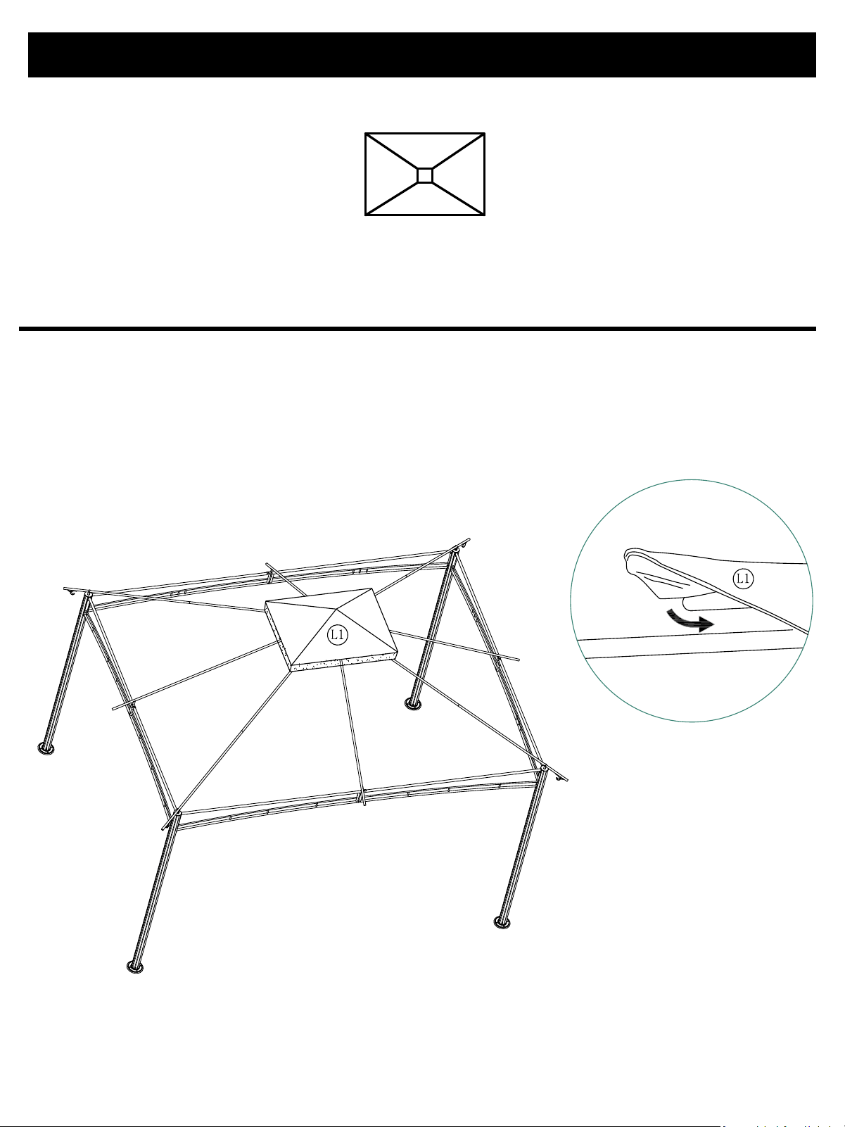
Assembly Instruction
Step 10:
Page 14 of 20
NOTE:
Assemble Part L1(Vent Cover): Slip its four corners over the tubes of F1(Short Slanted
Roof Tube).
Part L1:Vent Cover
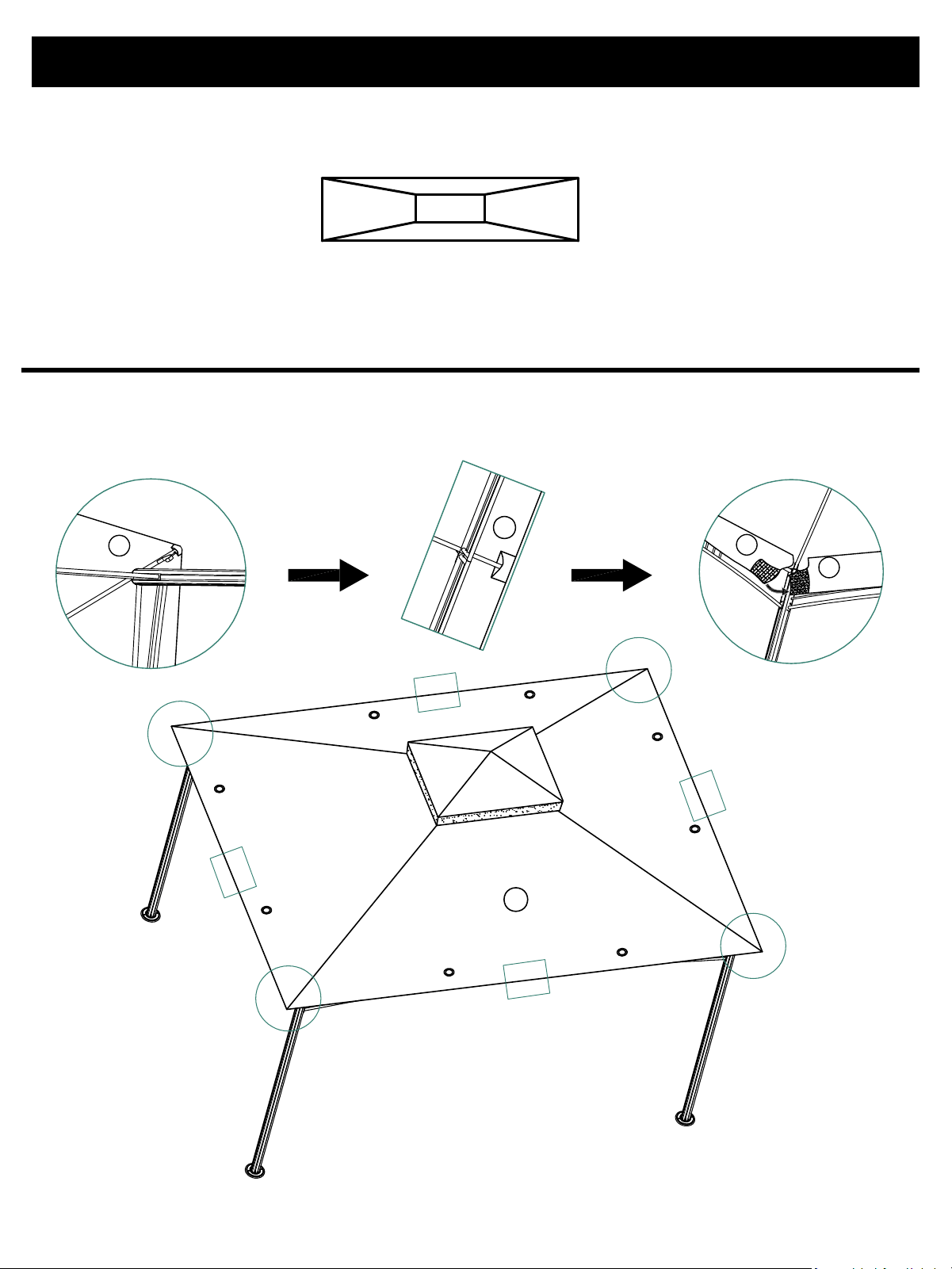
Assembly Instruction
Step 11:
Page 15 of 20
NOTE:
Assemble Part L2(Roof):First slip its four corners over the corresponding parts, then
attach the middle Velcro.
Part L2:Roof
L2
L2
L2
L2
L2
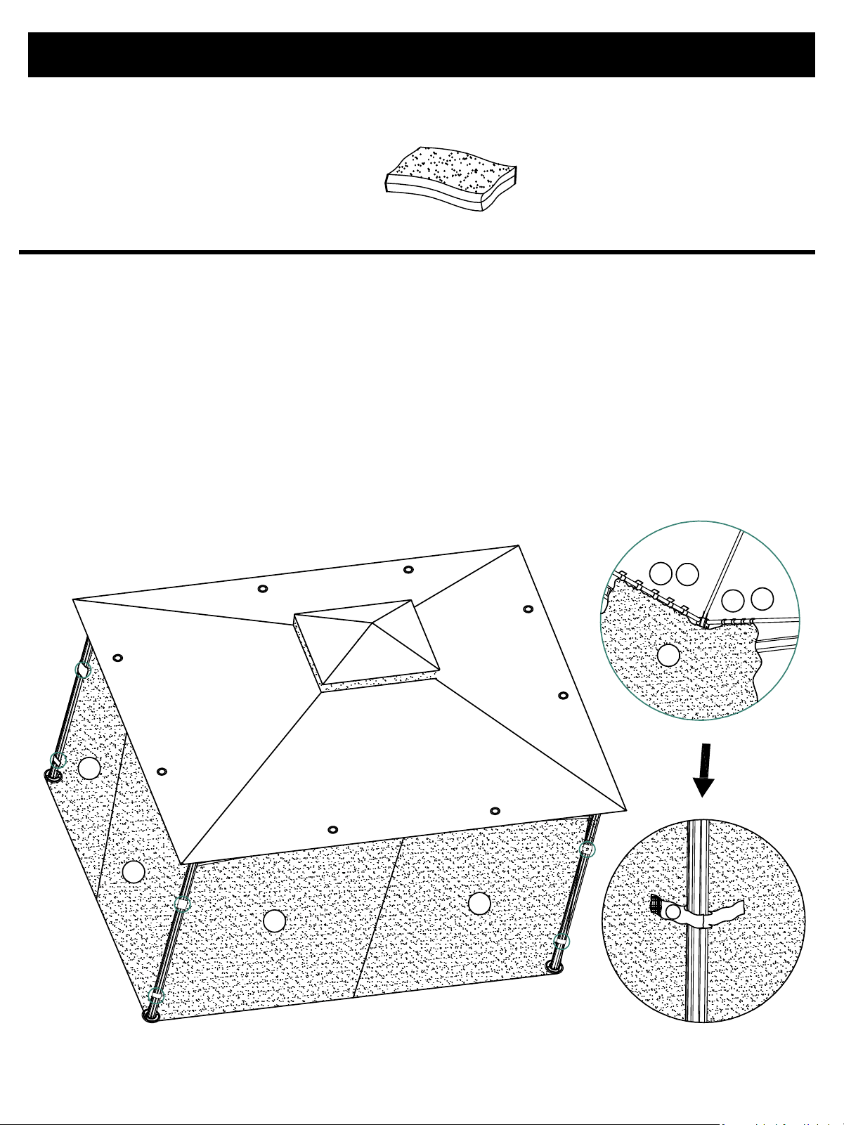
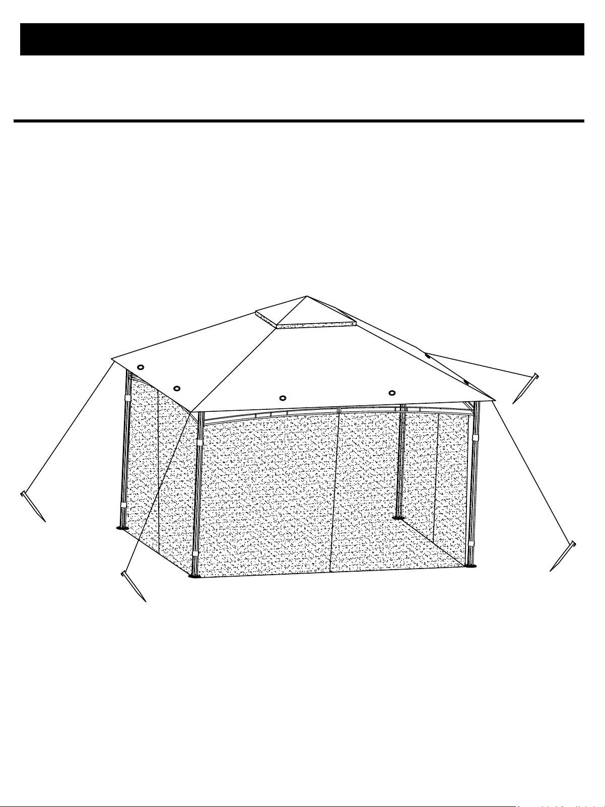
Assembly Instruction
Step 12:
Page 16 of 20
NOTE:
First, locate the tiebacks on Part M(Mosquito Netting), then identify the long side and
short side of each net panel. Next, attach the mosquito netting to the interior of the garden
house using hook and loop straps, making sure to align it with the long and short sides of
the frame
Find the tiebacks that are sewn to the outer corners of the mosquito netting. When
securing the net, always wrap these tiebacks around the corner posts of the garden
house.
Part M:Mosquito Netting
M
M
M
M
M
E
D
B
C
M
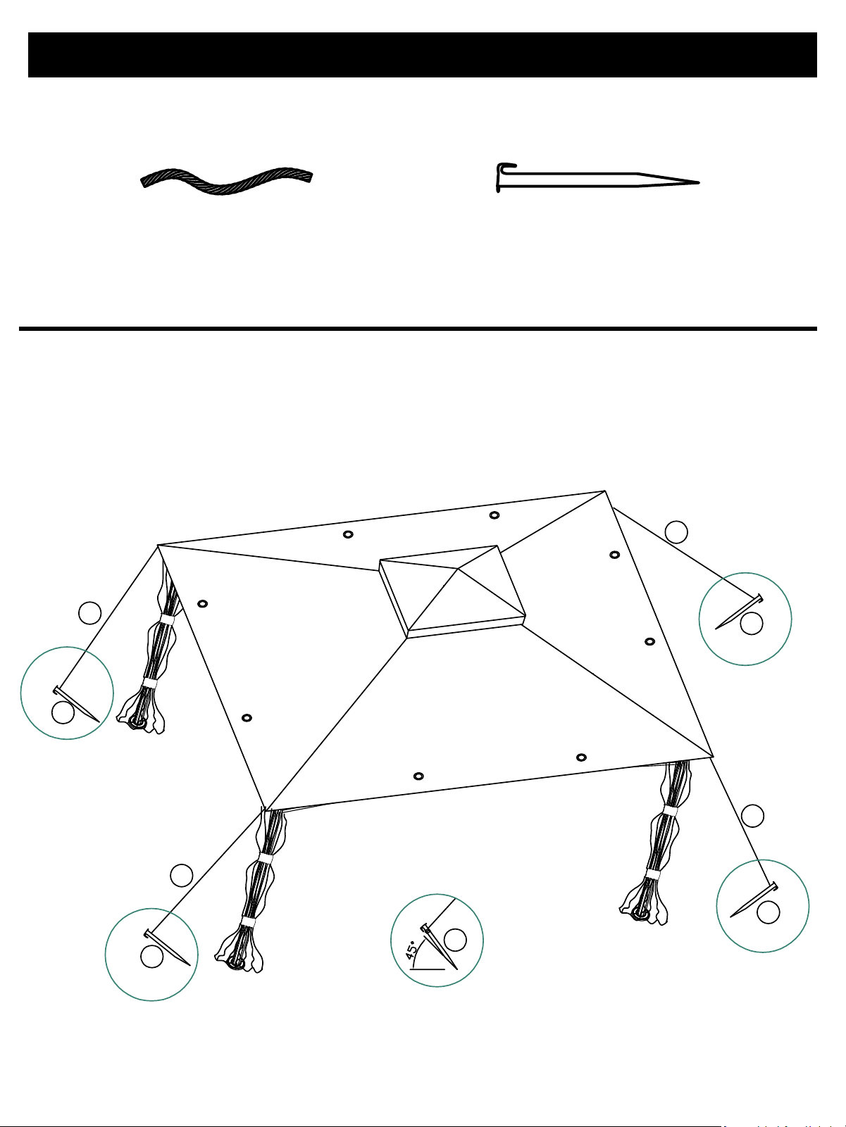
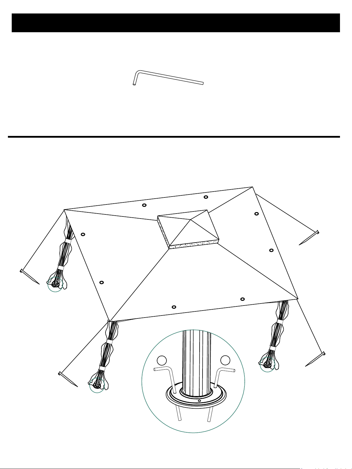
Assembly Instruction
Step 13:
Page 17 of 20
NOTE:
Measure the farthest possible distance from the post—this ensures Part P (Rope) length is
used to its fullest—then fasten Part Q(Ground Stake) to the ground at a 45-degree
angle.
Part P:Rope 4pcs Part Q:Ground Stake 4pcs
P
P
P
P
Q
Q
Q
Q
Q
Assembly Instruction
Step 14:
Page 18 of 20
NOTE:
First, carefully adjust the position of the canopy gazebo. Make sure all four posts stand
perfectly upright on level ground. Then, for each post base, hammer two Part O (Post
Anchor) through its holes and into the ground.
Part O:Post Anchor 8pcs
O
O
Assembly Instruction
Page 19 of 20
Step 15:
NOTE:
Upon completion of installation, verify that each bolt is securely tightened.

LIMITED WARRANTY
1. Manufacturer warrants this Product to be free from defects in workmanship and materials for
aperiod of one year from the date of purchase, PROVIDED claims are submitted, in writing with
proof of purchase.
2. If any part of this item fails because of a manufacturing defect within the Limited Warranty
Period, Manufacturer offers to replace such part(s) provided that such parts have not been
improperly repaired, altered, or tampered with or subject to misuse, abuse, or exposed to corrosive
conditions. This Limited Warranty is, however, subject to certain limitations, exclusions, time limits,
and exceptions(Hereinafter Conditions") as listed below. Read these Conditions carefully.
3. This Limited Warranty shall be limited to the replacement or repair of any part(s) which
Manufacturer determines, after reasonable examination, to have been defective at the time of
manufacturing andmanufacturer's obligation(s) shall be limited to replacement, if any, of defective
part(s) which shall be shipped at Original Purchaser' s expense to Original Purchaser' s designated
shipping address.
4. This Limited Warranty is given to and covers the ORIGINAL PURCHASER ONLY and such coverage
terminate: One year from the date of purchase.
5. DAMAGE LIMITATION WARNING: In no event shall manufacturer be liable for any incidental or
consequential damages, including (but not limited to) loss of use of the product, loss of time, loss of
food, inconvenience, expense for travel, transportation lodging expenses, loss by damage to
personal property, or loss of income, profits, or revenue.
6. MANUFACTURER'S OBLIGATION: Manufacturer's liability shall be limited to the delivery of a
good,merchantable Product and, if necessary, the repair or replacement, at manufacturer' s
option,
of any defective part or unit.
7. TRANSFER LIMITATIONS: This Limited Warranty is not assignable or transferable. It covers only
the original purchaser.
8. RESERVED RIGHT TO CHANGE: Manufacturer reserves the right to make changes or
improvements to products it produces in the future without imposing on itself any obligations to
install the same improvements in the products it has previously manufactured.
9. This warranty does not cover inclement weather due to high winds, excessive snow or rain,
andother extreme weather issues.
10.This Limited Warranty gives the Original Purchaser specific legal rights but there may be other
rights which vary by jurisdiction.
11. Rust or corrosion is not deemed a manufacturing or materials defect.
12. If any defect is found, please call our customer service department at (888)-380-7953 for help,
or write to us at Email: [email protected].
Page 20 of 20