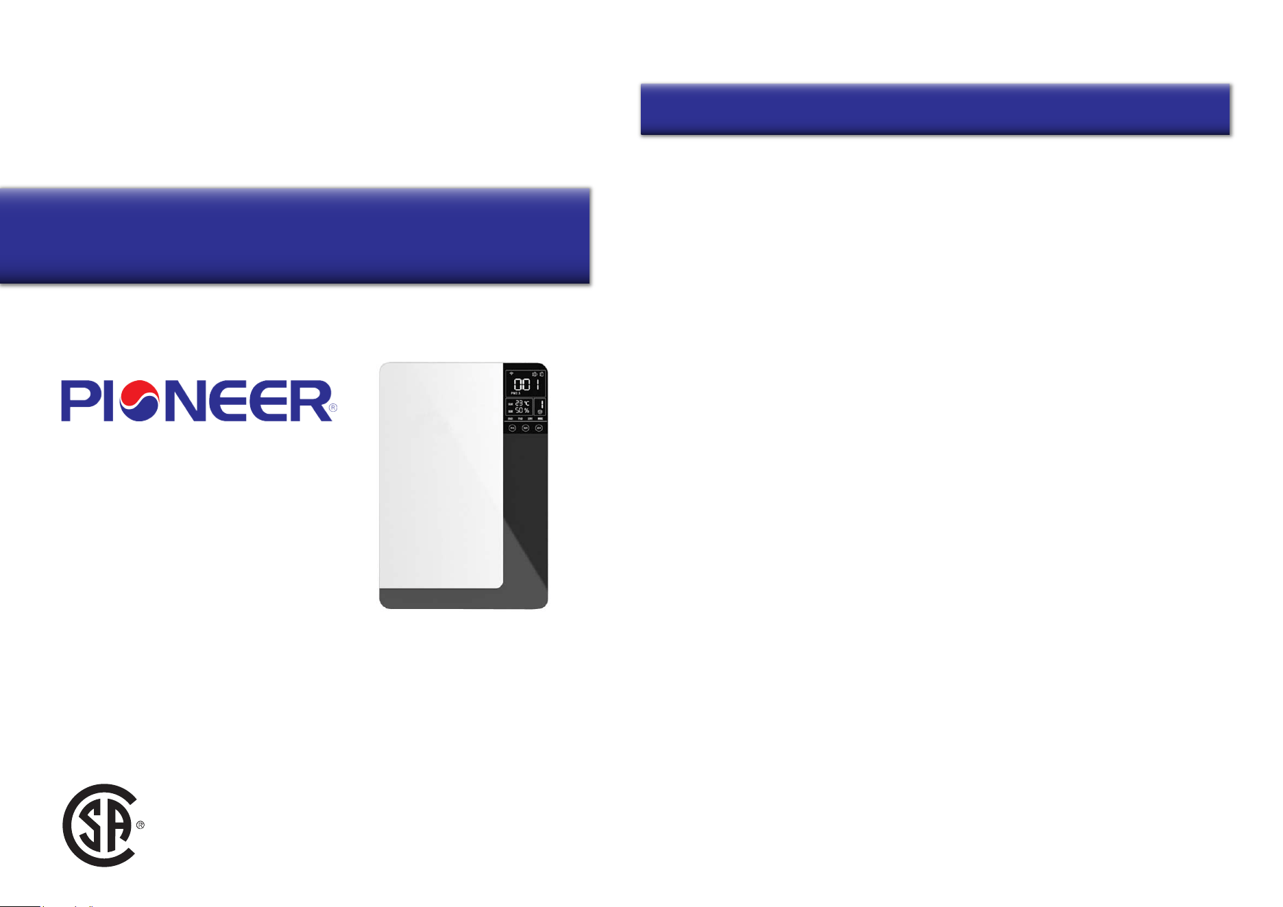
Applicable To Models:
- ERV150AHRPM25L
Attention
Please read this manual carefully before installing
or operating the equipment.
Be sure to save this manual for future reference.
Table of Contents
Accessories List........................................................................................................................................1
Safety Remarks.........................................................................................................................................2
Equipment Overview................................................................................................................................3
Specifications.............................................................................................................................................4
Operation Instructions.............................................................................................................................4
Wi-Fi Connection.......................................................................................................................................8
Installation Instructions.........................................................................................................................10
Maintenance...............................................................................................................................................13
Troubleshooting........................................................................................................................................15
Owner’s Manual of Pioneer®
Energy Recovery Ventilator
Contents
USC
1
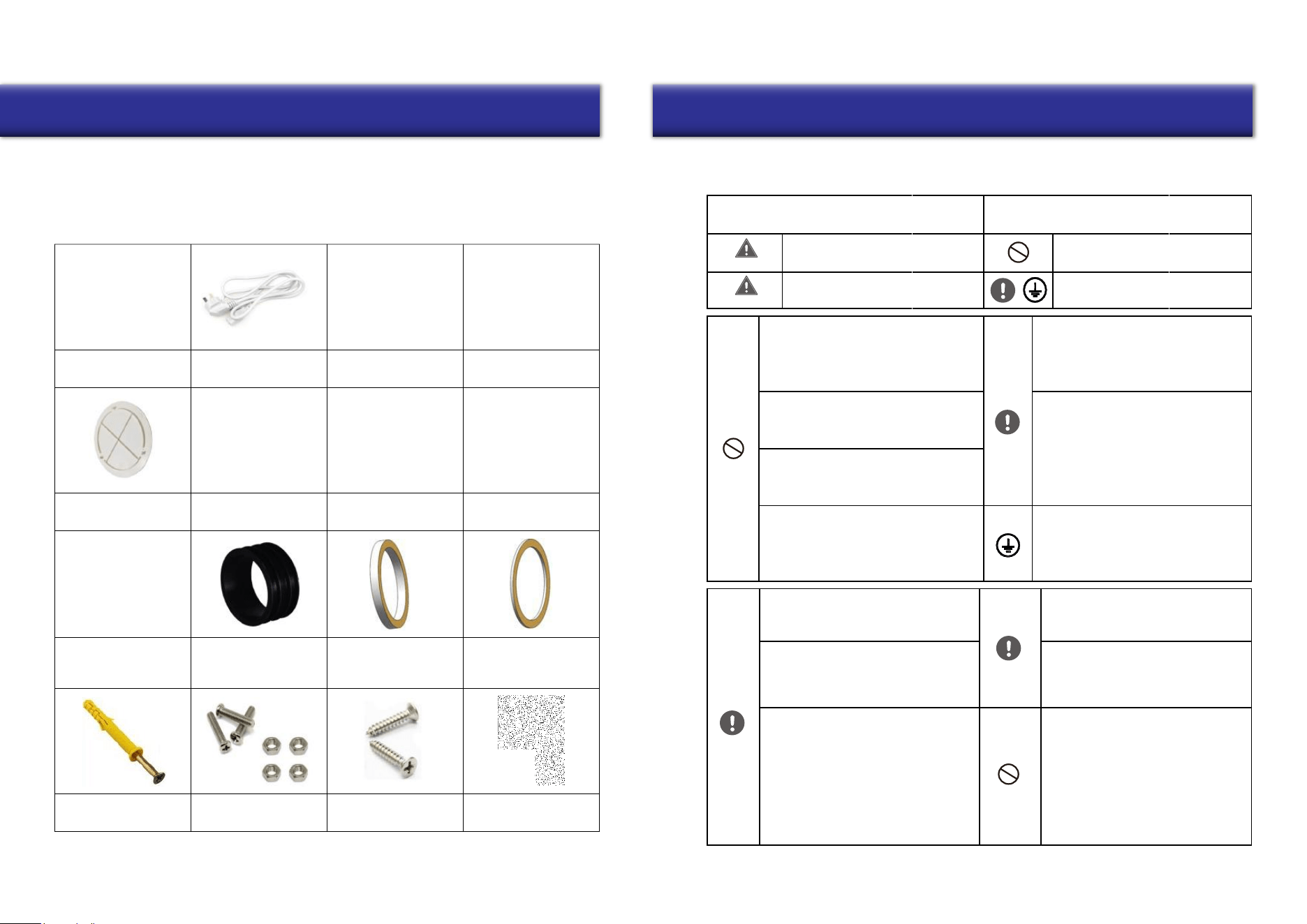
Your purchase includes the following items. Please verify the following upon unboxing:
1x Ventilator Unit
1x Operation Manual
As well as the below listed parts:
Installation Panel
1x
Power Cable
1x
Remote Controller
1x
OA / EA Side/Back Cover
2x
Air Vent Flange
2x
Air Inlet Grille
1x
Rain Proof Cover
2x
Rubber Sealing Ring
2x 2x
Back Seal Ring
Knock-On Anchor Bolt
5x 8x M3x6 Screws
8x M3 Nuts Tapping Screws
4x
PVC Straight Ducts
2x
Air Outlet Grille
1x
Side Sealing Ring
2x
Back Plate
Insulation Foam
Compliancy Required
2
Accessories List Safety Remarks
Please carefully read the following safety instructions prior to installation. Ensure that all steps
are followed and that the unit is installed correctly. Please observe all precautions in order to
avoid any injury or damage to equipment or property.
The following symbols indicate potential risk of
harm to persons or property.
Warning
Warning
Situations with a risk or death
or serious injury
Situations with a risk of injury or
equipment damage.
The following symbols indicate compliance
which must be observed.
Not Allowed/Stop Immediately
Do not install the unit in a location that
may be exposed to combustible gas
leaks. If combustible gas accumulates
around the unit, it may cause fire.
Take care to prevent obstruction of the
indoor outlet and return air inlet, so as
to avoid fan or airflow abnormalities.
Do not attempt to operate the machine
with wet hands, especially any plugs or
electrical parts.
Do not attempt to remove the motor
or circuit board, to prevent electric
leakage or discharge.
After installation, ensure that any
unqualified persons do not try to move
the equipment, to avoid risk of damage.
Be sure to turn off the power
before performing any maintenance
or coming into contact with any of
the electrical components.
Please follow the maintenance
instructions in this manual: clean
the return air filter and the entire
heat exchanger regularly.
Replace the primary filter and HEPA
filter regularly.
This product is intended for standard
applications. If used in special
circumstances, please first consult
with the manufacturer.
For powering off, please use the touch
screen controller. If not at home for a
long time, please cut power to the
system to maximize energy savings.
When cleaning, use a clean soft
cloth to wipe the machine, to avoid
scratches.
It is required to use a properly
grounded power supply.
Improper ground wire connection
may cause electric shock.
This product uses 110-120V ~ 60Hz
power supply and a three-pin plug.
Please use a suitable power supply.
Install the product in an environment
where humidity is less than 85%.
Do not introduce fresh air in a
hazardous environmental area. The
fresh air outlet should be far away
from kitchen ventilators, garbage
dumps, pollution discharge outlets,
and air conditioning outdoor units.
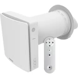
The wall mounted energy recovery ventilator integrates air purification and energy recovery.
This product is made up of a supply fan, exhaust fan, heat exchanger, primary filter, medium filter,
activated carbon filter, with a HEPA filter at the OA* side and a primary filter at the RA* side.
The system has the following operating principles and benefits:
Working Principle and Functionality
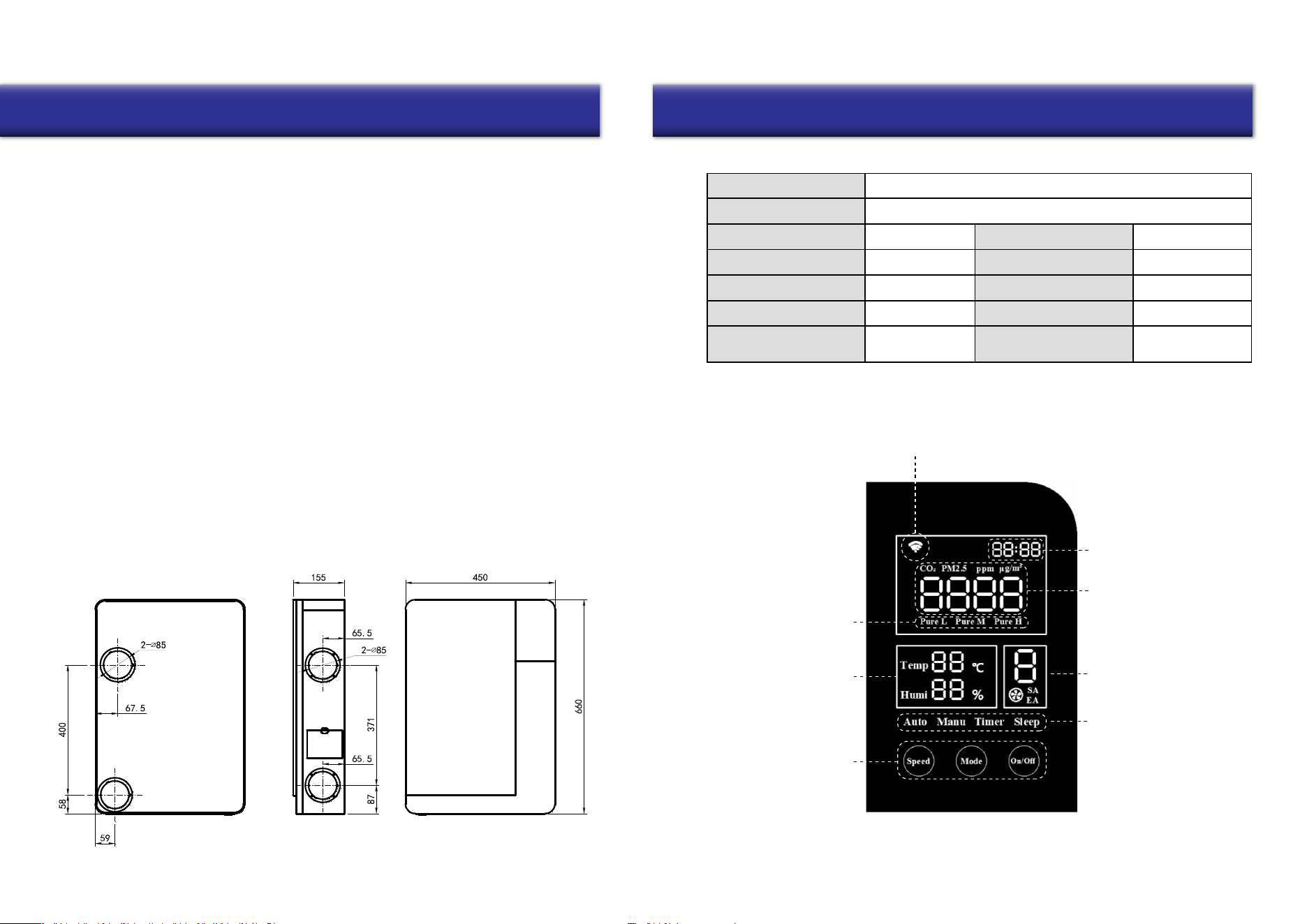
Dimensions (mm)
3
Technical Specifications
Display Screen Main Interface Overview
4
Equipment Overview Specification and Operation Instructions
1. Fresh Air Purification: Outdoor air is pulled in by the supply fan and passes
through the primary filter, where it will then exchange energy with the RA in the
heat exchanger. The fresh outdoor air will then be further filtered by the HEPA
filter, before finally being sent indoors. Meanwhile, the EA fan will exhaust stale
indoor air outside, so as to improve and replenish the indoor air quality.
2. Energy Recovery: Typically the air temperature difference between indoor and
outdoor is quite large. Therefore, when the indoor air is at a comfortable temperature
and humidity, if fresh air is merely filtered before being introduced inside, then it will
increase the burden on and thereby the power consumption of the air conditioning
or heating system. In order to avoid this side effect, your new Pioneer® ERV system is
equipped with a heat exchanger, which can recover the energy of EA, and then recycle
to OA. This function will greatly reduce these energy losses, and works all year-round.
ERV150AHRPM25L
88
110/120
99
82
22
Located on the
ventilator body
IP Class
Frequency (Hz)
Noise dB(A)
Input Power (W)
Dimensions WDH (in.)
IPX2
60
36
35
17”-3/4 x 6”-1/8 x 26”
Model Number
Airflow (CFM)
Voltage (V)
Filtration Capacity (%)
Temp. Efficiency (%)
Weight (Lb)
Serial Number
1. Wi-Fi Connection Status
(Devices without Wi-Fi will remain blank)
2. Cl
ock / Timer
3.
Current Indoor CO
2
Concentration / PM2.5
Value
6. Current Operation Speed
of th
e Equipment
7. Mode Status
Indicators
5.
Current Indoor
Air
Temperature and
Humidity
Values
8. Adjustable Touch
Interface
Buttons
4.
Purification
Status
Indicators
Overview of Control Buttons
• Press the “On/Off” button to turn on or off the machine.
• After startup, use the “Mode” button to switch modes as follows:
Auto > Manual > Timer > Sleep > PURE L > PURE M > PURE H
• Under “Manual” mode, use the “Speed” button to select from speeds 1-8.
Operation Modes Overview
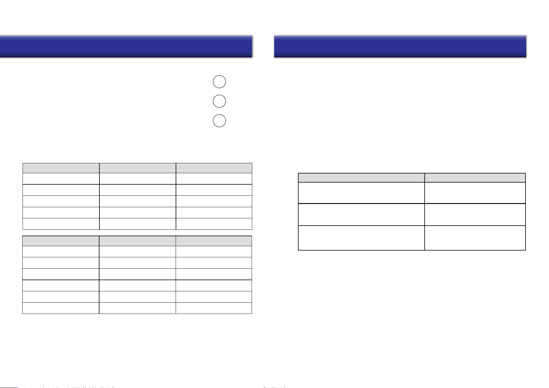
• In AUTO mode, the system will adjust supply air volume according to the indoor CO2/PM2.5 range,
with the corresponding speed as follows:
Excellent
1
Good
3
Light Impurities
5
Medium Impurities
7
Serious Impurities
8
5
PM2.5 Value
Air Quality Status
Operational Speed
Excellent
1
Good 2
Light Impurities 4
Medium Impurities 5
Heavy Impurities 7
Serious Impurities 8
6
Combinations Result
1. Reset Wi-Fi
2. Clear connection information
Reset to Factory default setting
Set RS485 address
Button Combinations
Operation Instructions Operation Instructions
Speed
Mode
On/Off
CO2 Value
Air Quality Status
Operational Speed
0 ≤ CO2 ≤ 450
0 ≤ PM2.5 ≤ 35
450 < CO2 ≤ 1000
35 < PM2.5 ≤ 75
75 < PM2.5 ≤ 115
115 < PM2.5 ≤ 150
150 < PM2.5 ≤ 250
1000 < CO2 ≤ 1500
1500 < CO2 ≤ 2000
CO2 > 2000
PM2.5 > 2000
Note: To ensure sufficient indoor fresh air supply, the speed will rise automatically
after model “Auto” runs for some time. After 5-10 minutes, it will revert to the previous
speed. During this time, the screen will display a different speed from the above chart.
• Under any mode, the unit will be switched to “Manual” mode when the user presses the “Speed”
button. Pressing “Speed” again allows configuration of the SA/EA fan speed. When “SA” flashes,
use “Speed” button to set SA fan speed from speeds 1-8. Pressing “Mode” switches to “EA” fan
setting. When “EA” flashes, pressing “Speed” configures the fan to speeds of 1-8. Once finished,
press “Mode” to save and exit, otherwise the system will automatically save and exit after 15s.
• “TIMER” mode will be configured via the handheld remote controller.
• With “SLEEP” mode, the system runs at the lowest speed, and the screen brightness will be
lowered to half of the normal setting.
• Modes “PURE L”, “PURE M”, and “PURE H” are for rapid improvement of the indoor air quality,
with L/M/H being Low/Medium/High. The speed of performance can be configured as needed.
(Ventilator is ON)
Long pressing “On/Off” + “Speed” together
(Ventilator is either ON or OFF)
Long pressing “On/Off” + “Mode” together
(Ventilator is OFF)
Long pressing “On/Off”
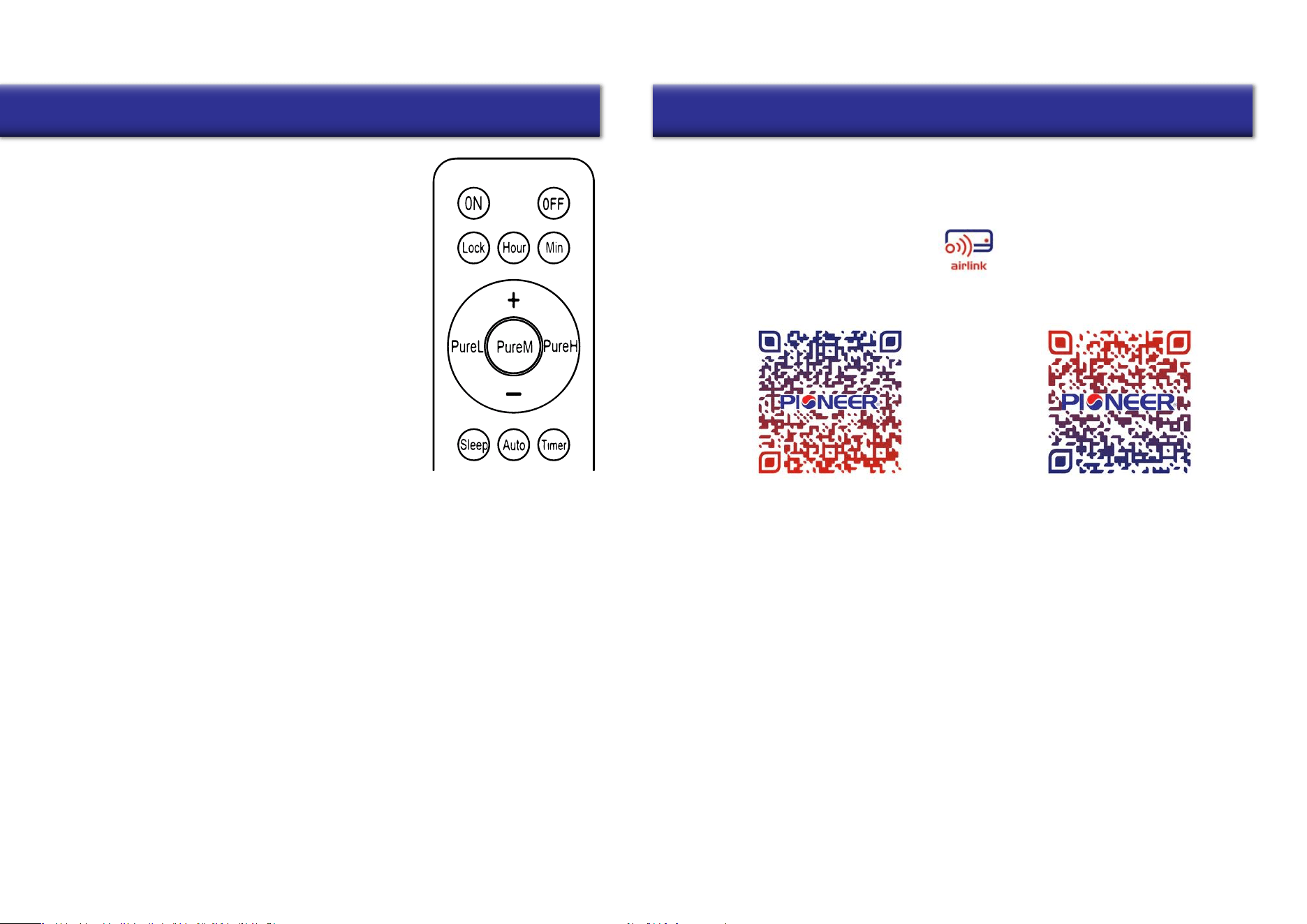
Remote Controller Overview
Button Functions:
Time Setting:
1. Pressing “On” turns on the ventilator.
2. Pressing “Off” turns off the ventilator.
3. Pressing “Lock” turns off the display,
(Pressing again turns on the display).
Note: When blinking, if there is no operation in 15s, the blinking
will end and settings will be saved automatically.
7. Pressing the “Sleep” button yields the same results that are described on Page 6.
8. Pressing the “Auto” button yields the same results that are described on Page 6.
10. Pressing the “Pure L/M/H” buttons yields the same results that are described on Page 6.
7
Installation of “Pioneer Airlink” smartphone application
Search for “Pioneer Airlink” in the Google Play Store (for Android users) or the App Store (for iOS users).
Note that a 2.4GHz Wi-Fi connection is needed to use the Wi-Fi control feature.
Or, scan the below QR code to download the app from the respective app store.
Wireless Control App Setup Process
1. Registration and Log-In:
If you do not already have a “Pioneer Airlink” account, please create and account and log-in
by following the below steps:
2. Adding a New Device:
8
Operation Instructions Wi-Fi Connection
Download iOS App
Download Android App
4. Pressing the “Hour” button will make the “Hour” part at the top
right corner of the ventilator screen begin blinking. Pressing “+”
will increase time, pressing “-” decreases time. Pressing the
“Hour” button will save the setting and exit hour-setting mode.
5. Pressing the “Minute” button will make the “Minute” part at the
top right corner of the ventilator screen begin blinking. Pressing
“+” will increase time, pressing “-” decreases time. Pressing the
“Minute” button will save the setting and exit minute-setting mode.
6. Pressing "+" changes the fan speed from slower to faster, and pressing "-" changes the fan
speed from faster to slower (Except for when adjusting time, or when the system is shut down).
When in “MANUAL” mode, the SA indicator will flash, and pressing the "+" or "-" buttons will adjust
the SA speed. After configuring SA speed, pressing “Pure H” will switch to air speed selection of EA.
(During this step, the “ Pure H” button functions as the “Mode” button).
Pressing "+" or "-" will adjust the air speed.
After configuring the EA speed, pressing the “Pure H” button once more will
quit the speed configuration (or automatically when no input is received for 15s).
The air speed of SA and EA will be saved accordingly.
9. Pressing “Timer” will enter Timer Mode, and the time shown at the top right corner of
the machine screen will begin blinking. Pressing “+” increases time and “-” decreases
time, in interval of 30 minutes. The longest time setting is 8 hours, and the default
time setting is 00:00.
Pressing “Timer” once more will save and exit the timer setting, and the top right corner
of the ventilator screen will revert to displaying the current time again.
Note: When blinking, if there is no input for 15s, the blinking will end, and settings saved automatically.
Once timer setting is completed, pressing the “Timer” button at top right corner of the display will
display the remaining time for the timer setting. At this time the timer can be set again, if needed.
To cancel the timer function, set the time to 00:00.
i. Approve the “User Agreement” and “Privacy Policy” when they appear by tapping “I Agree”.
ii. Tap the “Sign Up” button, choose your country, and enter your mobile number/e-mail to register,
tick “I Agree” on “User Agreement and Privacy Policy”, then tap the “Get Verification Code” button.
The phone or e-mail that you’re registering will receive a registration verification code.
iii. Enter the verification code and select a password. You will then either land on the homepage of
the App, or back to the login interface to log into the app, by using the account you just created.
i. Confirm that your phone is connected to Wi-Fi (2.4GHz networks only, 5Ghz will not work).
Tap the “+” at the top-right corner of the homepage, to enter the device selection page.
ii. Once you’ve entered this page, head to your Pioneer ERV system and long press “On/Off + Speed”
buttons when the ventilator is turned ON, until the Wi-Fi symbol on the display screen flashes.
(Fast flashing indicates Wi-Fi connection, slow flashing refers to hotspot network.)
3. Basic Control Overview
4. Modify the System’s Name
i. Tap the icon at the upper right corner in the homepage to enter into the settings menu.
ii. Tap the icon to enter the setting interface, tap the “Name” button to enter your desired
name, then tap the “Save” button to save the system’s new name.
5. Device Authorization and Device Sharing
6. Device Deletion (Unbinding)
7. User Information Modification
8. Signing Out
9
Wi-Fi Connection Installation Instructions
Energy Recover Ventilator Installation
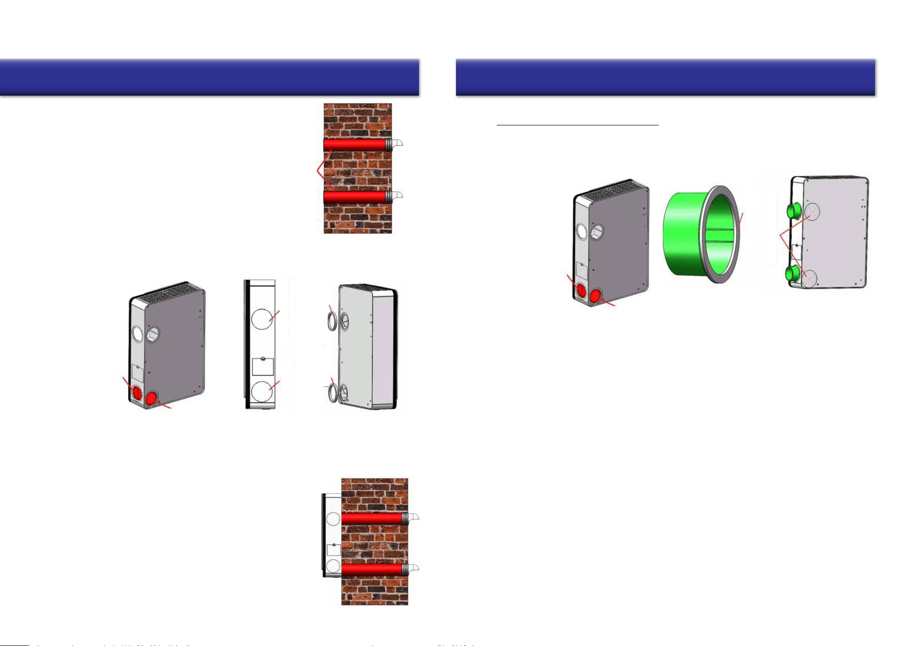
Scenario 1: Rear Installation
Note: The OA inlet and EA outlet hole sizes is given according to the Pioneer accessories (straight PVC pipes).
If your piping is of a different size than what is included, ensure the wall holes are matched accordingly.
3. Fasten the flange to the installation panel, using the included M3x12 bolts+nuts.
PVC Pipe
Rubber Sealing Ring
Rain Proof Cover
Air Inlet/Outlet Grille
Tapping Screw
Tapping Screw
10
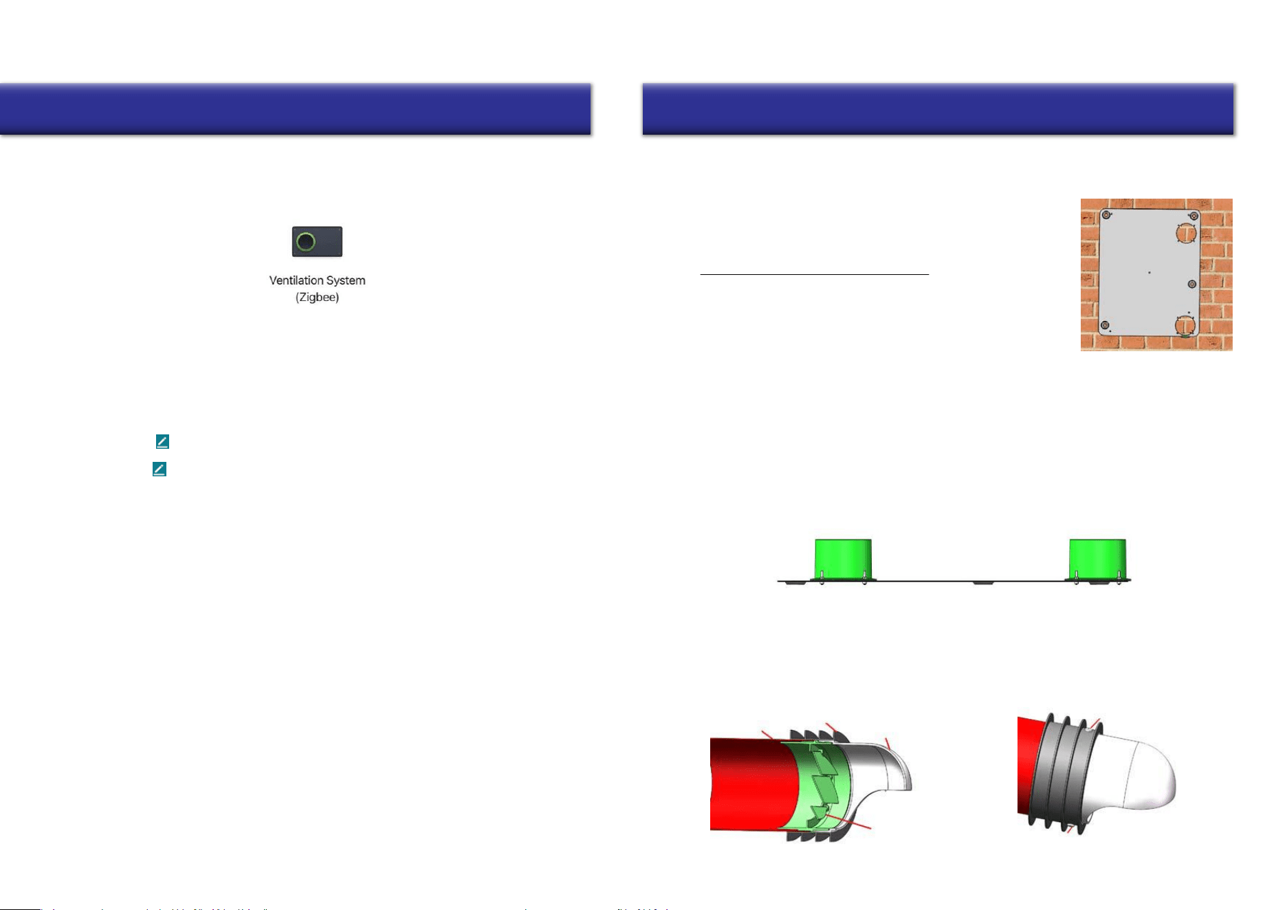
iii. Select the “Small Home appliance” category, and scroll downward to locate the “Ventilation
System (Zigbee)” icon, as shown below. After selection, follow the on-screen instructions step
by step, until the system is successfully paired. Double-check that the data being enterered
(such as Network passwords) is accurate.
Once connected, navigate to the homepage of device in the App. Tapping the “On/Off” button
modifies the operating status of the ventilator. Tapping the “Speed” button adjusts the airflow.
(Different models may have some variation or different operations).
i. The primary user paired to the device must enter the settings menu (as instructed in
“4. Modify the System’s Name”), then tap “Device Sharing” to open the sharing prompt.
ii. Once in the sharing prompt, enter the account number that you want to share access to the
equipment to, and click “Done”.
iii. The shared user account will then appear on the menu if the sharing process was successful.
i. Enter into the settings menu (as instructed in “4. Modify the System’s Name”), then tap on
“Device Removal”.
ii. Tap on “Remove Binding”, followed by “Confirm”. The system will then be unbound.
i. Tap the “I” on the bottom right corner of the homepage.
ii. Tap on the picture area to enter the user information page.
iii. Once inside the user information page, you can all modify user information,
including avatar, username (nickname, account number, and security, etc.).
i. Tap on “Me” on the bottom right corner of the homepage, then tap the “setting” button.
ii. Select "Sign Out" at the bottom to logout from the app.
Choose a suitable installation location for where the unit will ultimately reside, selecting from either
the rear or side of the equipment for the air inlets and outlets.
Follow the installation steps for the selected face (rear or side)
as given below:
1. Choose a suitable location on the wall where the equipment will be
mounted, and mark where the OA inlet and EA outlet locations will
be. Also mark the 5 mounting holes of the installation panel on wall.
2. Drill 2 holes in the wall for the fresh air inlet and exhaust air outlet, each with a diameter of 4 inches.
The 2 holes should angle downward toward the outside to prevent rain water ingress, with a minimum
downward slope of 1/4 inch per foot (18mm per meter). For the 5 mounting holes, recommended size is
1/4” drill bit and 2-3/4 in. deep hole (Φ6x70mm). Insert the 5 plastic anchors into the mounting holes.
4. According to the thickness of the wall, cut the suitable length of the PVC pipes.
Connect the PVC pipes to the OA and EA accessories as follows:
• OA side: PVC pipe + Air inlet grille + Rain proof cover + Rubber sealing ring + Tapping screws
• EA side: PVC pipe + Air outlet grille + Rain proof cover + Rubber sealing ring + Tapping screws
Note: Before installing the fastening screws, it is necessary to drill holes of Φ 1/8” (3mm).
Note on clearances:
• Ventilator bottom to the floor around 5 feet (1.5 meters)
• Ventilator left and right side to the wall no less than 1 foot (0.3 meter)
11. Once installation is completed, power on the ventilator.
Installation Instructions
Seal any gaps
11
Scenario 2: Side Installation
4. For the 5 mounting holes, recommended size is 1/4” drill bit and 2-3/4 in. deep hole (Φ6x70mm).
Drill the holes with reference to the panel, and insert the 5 plastic anchors into the mounting holes.
12
Installation Instructions
5. Slide the assembled ducts into the wall. Ensure that the rain cover
is appropriately oriented downwards, to prevent rainwater ingress.
Next, seal any gaps between the duct and the wall, if present, using
appropriate field-supplied materials like silicone or waterproof putty.
6. Secure the ERV installation panel onto the wall, by using the
supplied knock-on anchor bolts.
7. Since the above installation is for the “Rear Installation Scenario”, cut the EPS “Rear Cover” located
at the OA vent, as shown in the below picture. DO NOT cut the EPS “Side Cover” in this case.
2. Since the above installation is for the “Side Installation Scenario”, cut the EPS “Side Cover” located
at the OA vent, as shown in the above picture. DO NOT cut the EPS “Rear Cover” in this case.
Cut the side cover when
doing side installation
Cut the rear cover when
doing rear installation
Side outlet/inlet cover
Rear outlet/inlet cover
Side sealing ring
Side outlet/inlet cover
Rear Sealing Ring
Rear Sealing Ring
8. Place the 2 round OA and EA Side/Back covers on the side of the ventilator, to cover up the Side Air
Inlet and Side Outlet (as shown above). Secure the 2x seal rings to the rear of the air inlet + outlet.
9. Secure the rear plate thermal insulated cotton/foam onto the rear side of
the ventilator if necessary (near the OA side). This assists with preventing
condensate water when the ventilator is deployed in cold areas.
10. Hang the ventilator onto the installation panel. Adjust the 4 pieces M5x18
hanging screws on the back of the ventilator to suit the installation panel.
Cut the side cover when
doing side installation
Cut the rear cover when
doing rear installation
1. Secure the 2x sealing rings on to the side flanges. Fasten the flanges to the ventilator side using the
included 8x M3 bolts & 8pcs M3 nuts. Use caution to prevent dropping hardware into the ventilator
during installation.
3. Choose a suitable location on the wall where the equipment will be mounted, and mark where the
OA inlet and EA outlet locations will be. Also mark the 5 mounting holes of the installation panel on
the wall according to the ventilator placement.
Note on clearances:
• Ventilator bottom to the floor around 5 feet (1.5 meters)
• Ventilator left and right side to the wall no less than 1 foot (0.3 meter)
5. Drill 2 holes in the wall for the fresh air inlet and exhaust air outlet, each with a diameter of 4 inches.
The 2 holes should angle downward toward the outside to prevent rain water ingress, with a minimum
downward slope of 1/4 inch per foot (18mm per meter).
Note: When drilling outlet holes on the wall, the opening hole size is only a recommended value. When installing the
ventilator by the “Side Installation Scenario”, the ducts should be flexible ducts (field supplied by the installer).
The final hole size on the wall should be selected by the installer, according to the diameter of duct to be used.
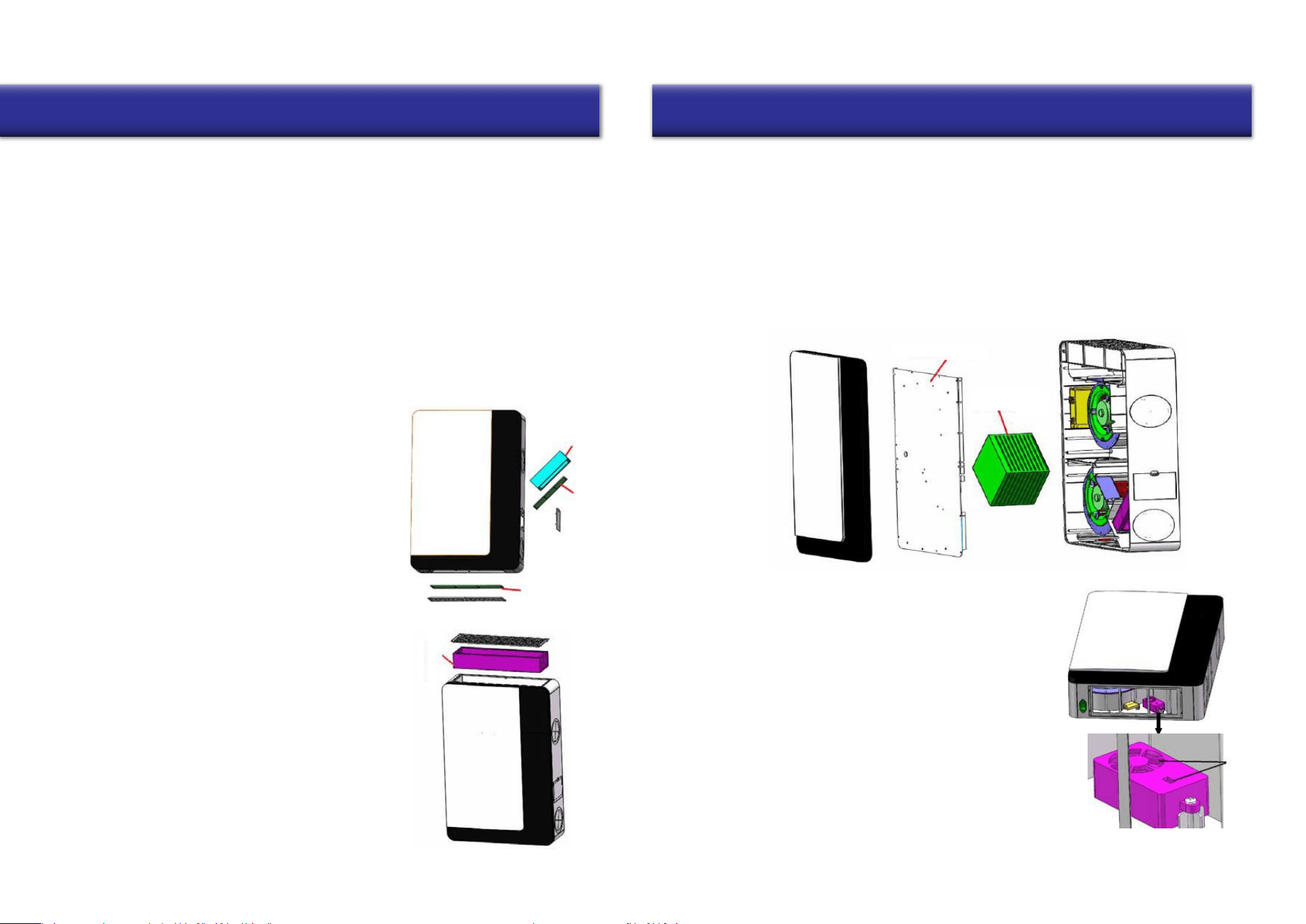
OA and RA Primary Filter Maintenance and Change
HEPA Filter Change
9. Secure the other end of the installed piping onto the flanges on the side of the ventilator.
OA Primary
Filter
OA Medium Filter
RA Primary Filter
13
Installation and Maintenance
Maintenance of Motor and Controller
Maintenance of the Heat Exchanger
14
Maintenance of PM2.5/CO2 Sensor
Maintenance
7. According to the thickness of the wall, cut the suitable length of the PVC pipes.
Connect the PVC pipes to the OA and EA accessories as shown on Page 10.
8. Slide the assembled ducts into the wall. Ensure that the rain cover is appropriately oriented
downwards, to prevent rainwater ingress. Next, seal any gaps between the duct and the wall,
if present, using appropriate field-supplied materials like silicone or waterproof putty.
HEPA Filter
Access Door
Plate Heat
Exchanger
6. Hang the ventilator onto the installation panel. Adjust the 4 pieces M5x18
hanging screws on the back of the ventilator to suit the installation panel.
10. Once installation is completed, power on the ventilator.
Attention: Power must be cut off to the device before attempting any maintenance.
Wait for the machine to come to a complete stop, to avoid any injury.
To be performed by trained and qualified personnel only. Do not attempt
as a homeowner. Contact the manufacturer with any questions.
The OA Primary and Medium Filters are located at the side of the
ventilator. The RA Primary Filter, used to filter large particles in
the air, is found at the bottom of the ventilator (as depicted in the
illustration to the right).
• Open the filter covers according to the marked locations on
the ventilator, and remove the primary and medium filters.
• The OA Medium Filter is not re-usable. It is advised to
replace this filter every 1-2 months for best results.
• The OA and RA Primary Filters are washable and re-usable.
It is recommended to replace these every 3-4 months.
The HEPA Filter is located at the top of the ventilator, as depicted
in the illustration to the right. It is used to filter smaller particles
of less than 2.5µm from the air.
• Remove the covers at the marked locations on the ventilator.
Remove the HEPA Filters and insert the replacement ones.
• It is recommended to change out the HEPA Filters every 8-12
months (based on the area) for best results.
The plate heat exchanger is found in the central-right area of the ventilator, and is an air-to-air type heat
exchanger. Its function is to keep fresh air and exhaust air separated, ensuring cleanliness and purity of
the fresh air, as well as effectively preventing any cross-contamination.
• Remove the ventilator from the wall. Unscrew the 6 separate long screws from the rear side of
the ventilator, and unscrew the access door. You can then remove the plate heat exchanger.
• Use a strong vacuum cleaner to remove any dust and dirt buildup from the heat exchanger.
• It is recommended to perform maintenance and cleaning of the exchanger every 3 years.
• For further maintenance queries, please contact the manufacturer.
In order to prevent buildup and blockage of the air quality
sensor, the sensor needs to be cleaned regularly.
• Remove the bottom grid, then locate and remove the
Return Air Primary Filter. Refer to the illustration on
the right for locating the filter.
• Use a hair dryer or air duster to clean the sensor.
(If using the hair dryer, use the “fan-only” setting.)
Abnormality Possible Causes Solutions
1. Sensor short circuit, or open circuit
1. Replace the affected filters.
Exclusions to the Limited Warranty Disclosure
The following situations and scenarios are not covered by the limited warranty:
15
Troubleshooting Contact Information
is a registered trademark of Parker Davis HVAC
International, Inc.
Parker Davis HVAC International, Inc.
3250 NW 107 Avenue, Doral, FL 33172 - USA
Tel : (305) 513-4488
Fax : (305) 513-4499
E-mail : [email protected]
Website : www.pdhvac.com
Pioneer product line, parts, and supplies are
available online for convenient ordering at:
www.highseer.com
www.pioneerminisplit.com
Scan the below code to visit our support page
where you can find more installation materials:
Copyright 2024, Parker Davis HVAC International, Inc., All rights reserved.
The design and specifications of this product are subject to change without prior notice
as development continues. Consult with the sales agency or manufacturer for details.
Refer to the equipment nameplate for all other applicable specifications.
Users can often perform basic self-troubleshooting using the below chart, in the case
of any faults or malfunctions.
The display does
not start up
1. Loose or bad contact of power plug
2. Power cable fault
3. Display fault
1. The PM2.5/CO2 sensor test probe is
covered by dust or debris
2. Sensor short-circuit, or open-circuit
1. Blockage at the Air Inlet/Outlets by
foreign matter.
2. Blockage of Primary or HEPA filter.
1. No feedback from Supply and/or
Exaust Fan
2. Other fan fault
3. Main control board fault
1. Poor fastening of the machine ducting
2. Foreign matter entering the ventilator
3. Fault of supply fan or exhaust fan.
1. Check whether the plug is
loose, and if so, reconnect it.
2. Replace the power cable with
one of same specification.
3. Contact the manufacturer for
a replacement or repair part.
No display or wrong
display of temperature,
humidity, or CO2 values
Insufficient Fresh Air
Excess particles at
the supply air outlet
No response to the fan
speed adjustment switch
(Code: E0, E1, E3)
Abnormal Noises
The PM2.5/CO2 value
displays abnormally, or
doesn’t display at all
1. Contact manufacturer for
service or suggestions.
1. Follow the PM2.5/CO2 sensor
maintenance method in the
manual to clean the sensor.
If not resolved, contact the
manufacturer for service.
1. Adjust or secure the ducting.
2. Contact manufacturer for
repair parts or replacements.
1. Locate and clear out any
observed foreign matter.
2. Clean or replace the filters.
1. Contact manufacturer for
repair suggestions.
2. Contact manufacturer for fan
replacement parts.
1. Overuse of Primary and/or HEPA filters
1. Sabotage during usage that is considered man-made and/or intentional.
2. Malfunction due to usage, maintenance, or repair that were not performed in
accordance with the instructions of this manual.
3. Damages caused by any force majeure.