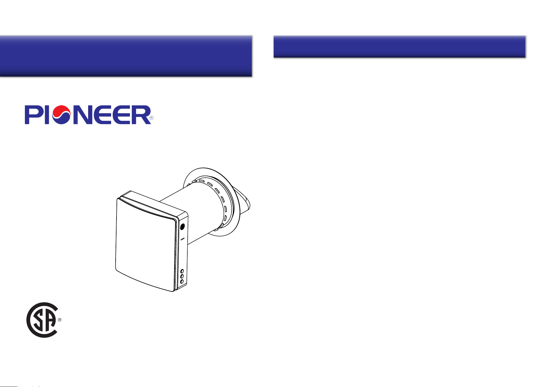
Applicable To Models:
- ERV035AVTTW5W
Attention
Please read this manual carefully before installing
or operating the equipment.
Be sure to save this manual for future reference.
303708
Table of Contents
Safety Remarks.........................................................................................................................................1
Product Information................................................................................................................................4
Specifications.............................................................................................................................................5
Overview......................................................................................................................................................8
Installation...................................................................................................................................................9
Operation....................................................................................................................................................12
Wi-Fi Connection......................................................................................................................................17
Maintenance...............................................................................................................................................21
Troubleshooting........................................................................................................................................23
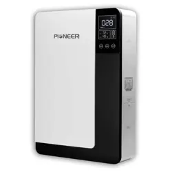
Owner’s Manual of Pioneer®
Energy Recovery Ventilator
Contents
USC
1 2
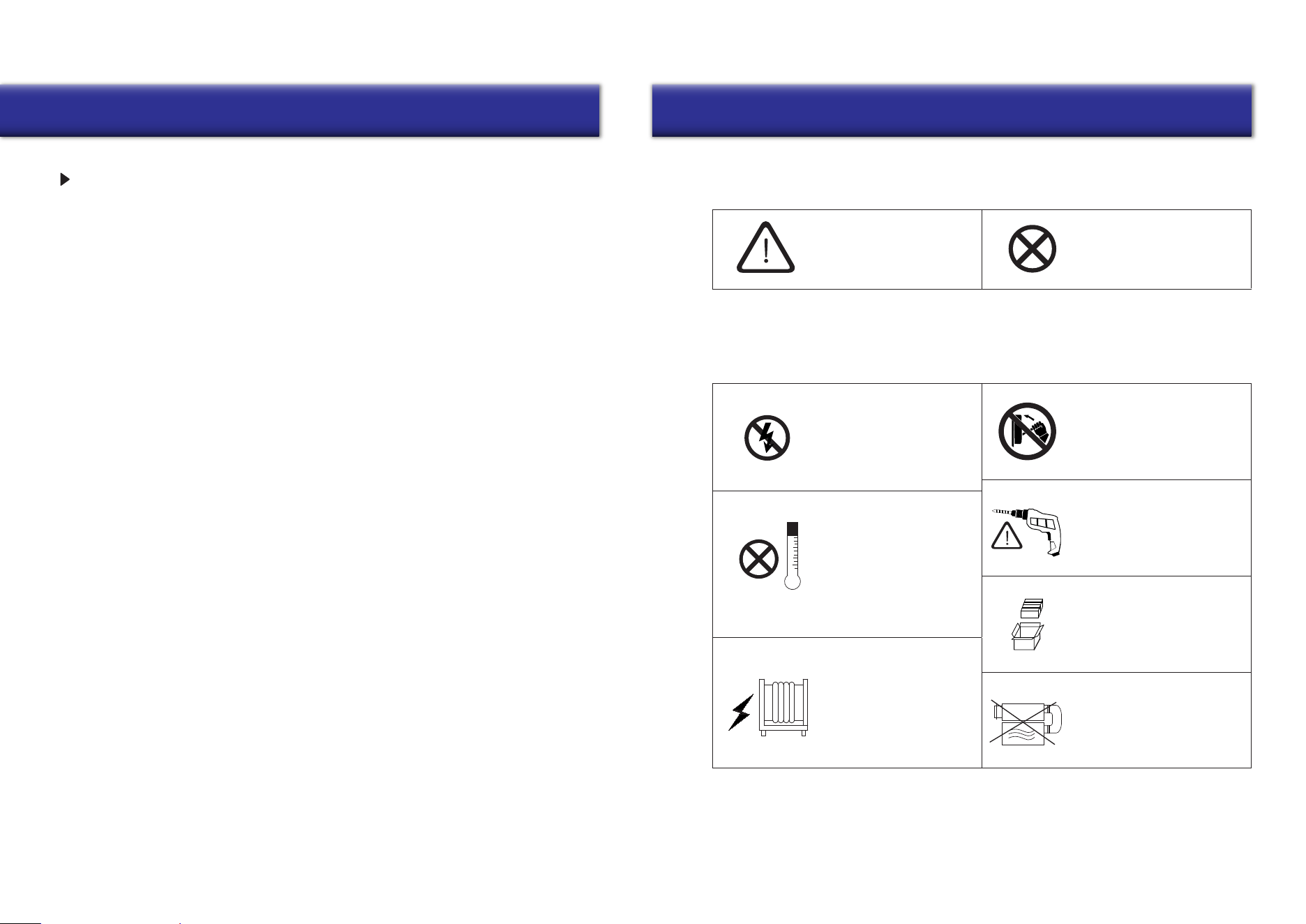
Safety Remarks Safety Remarks
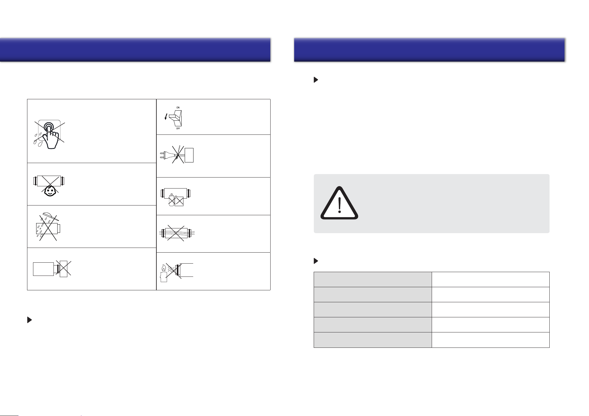
WARNING! NOT PERMITTED
Symbol Used In The Manual
Ventilator Installation Safety Precautions
The ventilator must be
disconnected from the
power supply before
installation or repair.
The ventilator must not
be operated outside
the temperature range
specified in the user’s
manual or in hazardous
or combustible areas.
Do not place any
heating devices or
other equipment in
close proximity to the
ventilator power cord.
Do not use damaged
equipment or conductors
to connect the ventilator
to power.
Unpack the ventilator with
care.
While installing the
ventilator, follow all local
safety regulations specific
to the use of electric tools.
Use the ventilator only
as intended by the
manufacturer.
SAFETY REQUIREMENTS
•
Read the user’s manual carefully before
operation and installation of the heat
recovery ventilator ERV035AVTTW5W.
•
Installation and operation of the ventilator
shall be performed in accordance with the
present user’s manual, as well as the
provisions of all applicable local and
national construction, electrical and
technical codes and standards.
•
The warnings contained in the present
user’s manual must be considered
seriously since they contain vital
personal safety information.
•
Failure to follow the safety instructions
may result in personal injury or
ventilator damage.
•
Read the manual carefully and keep it as
long as you use the ventilator.
•
This appliance can be used by children
aged from 8 years and above and persons
with reduced physical, sensory or mental
capabilities or lack of experience and
knowledge if they have been given
supervision or instruction concerning
the use of the appliance in a safe way
and understand the hazards involved.
•
Don’t allow children to play with the
appliance.
•
Don’t allow children to clean and maintain
the appliance without supervision.
• If the power cord is damaged, it must be
replaced by the manufacturer or its service
agent or similarly qualified person in order
to avoid a hazard.
•
It’s suggested to install the ventilator more
than 2.1 m (>7 Ft.) above the floor.
•
Precautions must be taken to prevent the
back-flow of gases into the room from any
open flue of gas or other fuel-burning
appliances.
•
Exhaust fans may adversely affect the safe
operation of appliances burning gas or other
fuels (including those in other rooms) by the
backflow of combustible gases. These gases
may cause carbon monoxide poisoning.
After installation of an exhaust fan such
as a partition fan or a duct fan, the operation
of an open flue gas appliances should be
tested by a competent person to ensure
that backflow of combustible gases does
not occur.
• Don’t recharge non-rechargeable batteries.
• Batteries must be inserted with the correct
polarity.
•
Remove used batteries from the appliance
and safely dispose of them.
•
If the appliance is to be stored unused for
a long period, the batteries should be
removed.
•
Don’t short-circuit the power supply
terminals.
•
Take good care of the remote control to
prevent children from attempting to
swallow batteries and/or cause any
related accidents.
3 4
Safety Remarks Product Information
Disconnect the ventilator
from the power supply
prior to maintenance.
Do not damage the power
cable while operating the
ventilator. Do not set any
objects on the power cable.
Keep explosive and
inflammable products
away from the ventilator.
Do not open the ventilator
while it is operating.
Do not direct airflow from
the ventilator toward any
open flames or candles.
Do not allow children to
operate the ventilator.
Do not touch the
controller or the remote
control with wet hands.
Do not carry out ventilator
maintenance with wet hands.
Do not block the air duct
when the ventilator is on.
Ventilator Installation Safety Precautions
Do not clean the
ventilator with water.
Protect all electric
parts from water ingress.
This user’s manual includes technical description operation, installation and mounting
guidelines, as well as technical data for the heat recovery ventilator ERV035AVTTW5W.
INTRODUCTION
1xVentilator
1xAccessories Bag
1x
1x
Remote Controller
User’s Manual
1xPackaging Box
USE
PACKING LIST
• The ventilator is designed to exchange air in apartments, villas, hotels, cafes, and other domestic
and public buildings. The ventilator is equipped with a ceramic energy regenerator, and a fan that
supplies fresh air as well as extracts stale air with energy recovery technology.
•
The ventilator is designed for through-the-wall mounting. The telescopic design of the fans
allows for installation in walls ranging from 280 mm (11”) to 470mm (18”-1/2) thick.
•
The ventilator is designed to remain connected to a power supply for continuous operation.
•
The transported air must not contain any flammable or explosive mixtures, evaporation of
chemicals, coarse dust, soot and oil particles, sticky substances, fibrous materials, pathogens,
or any other harmful substances.
INSTALLATION AND CONNECTION OPERATIONS MUST BE
PERFORMED ONLY BY PROPERLY QUALIFIED PERSONNEL
AFTER AN APPROPRIATE SAFETY BRIEFING.
THE VENTILATOR INSTALLATION SITES MUST NOT BE ABLE
TO BE ACCESSED BY UNATTENDED CHILDREN.
5 6
Specifications Specifications
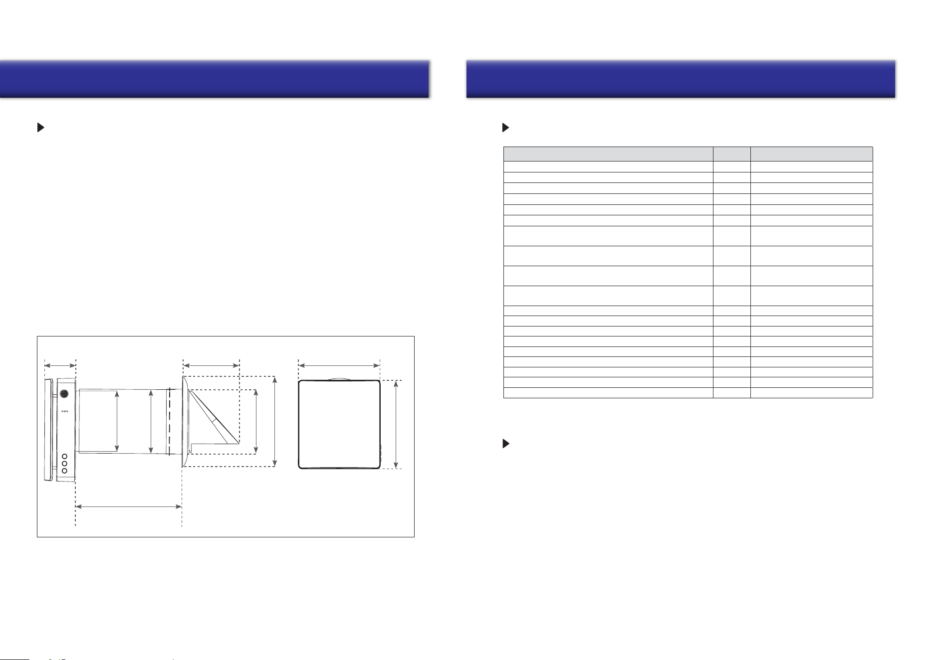
MAIN TECHNICAL PARAMETERS
Ventilator Overall Dimensions (in.)
• The ventilator is designed for indoor applications with an ambient temperature ranging from
-20°C (-4°F) to +50°C (+122°F), and a relative humidity below 80%.
• The ventilator is classified as a class II electric appliance.
• The Ingress Protection (IP) rating is IPX4.
• The ventilator design is subject to continunous improvement, so some models may differ
slightly from the models described in this manual.
11”~18”-1/2
5”-5/8
9”-7/16
10”-3/16
3”
Ø6”
Ø6”-1/4
Ø
6”-3/16
Ø 8”-15/16
Description Unit Value
Voltage V 100-240
Hz 50/60Frequency
W 9.7/10.7/11.5Input Power
A 0.14/0.15/0.16Current
-RPM (rated) 1000/1550/1800
- 2200RPM (max)
20/40/50
m
3
/h
Airflow (L/M/H) in supply/exhaust mode
(with F7 filter)*
10/20/25
m
3
/h
Airflow (L/M/H) in regeneration mode
(with F7 filter)*
11.8/23.5/29.4CFM
Airflow in supply/exhaust mode
(with F7 filter)*
5.9/11.8/15CFM
Airflow in regenerator mode
(with F7 filter)*
60
Max airflow (under fan boost mode) m
3
/h
35Max airflow (under fan boost mode) CFM
32.7 dB(A)Sound Pressure Level
% up to 97Heat Recovery Efficiency
- IPX4
mm (in.)
Ingress Protection Rating
158 (6”-1/4)
SEC - Class A
Air Duct Diameter
-Mounting Type Wall Mounting
kg (lb) 4.2 (9.25)Net Weight
DESIGN AND OPERATION
TECHNICAL SPECIFICATIONS
*Note: The airflow in supply/exhaust mode without an F7 filter is about 34/56/70 m
3
/h or 20/33/41.2 CFM,
and the relative parameters will be adjusted accordingly.
•
The ventilator consists of a telescopic air duct with adjustable length regulated by the position
of the inner air duct inside the outer air duct, the ventilation unit, and the ventilation hood.
•
F7 filter+prefilter and the ceramic energy regenerator are located inside the inner duct. The
filters are designed to purify supply air and prevent foreign objects from ingressing into the
regenerator and the fan.
•
The ceramic energy regenerator extracts energy from exhaust air to warm up or cool down
supply air.
•
The regenerator is equipped with a pull cord inside to facilitate its withdrawal from the
ventilator. The regenerator is installed on an insulated material which is also used as a
sealant.
•
The ventilator is able to be installed from the inner side of the wall.
7
8
Specifications Overview
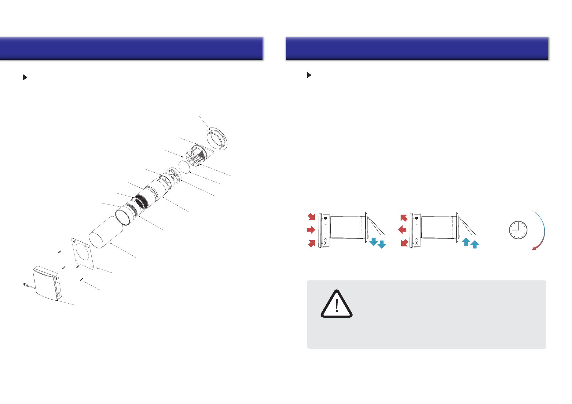
Main Machine
Phillips Screws
Back Installation Panel
INSTALLATION DRAWING
Outer Pipe
F7 Filter
Ceramic Heat Exchanger
Separation Circle
Filter Bracket
Heat Exchanger Bracket
Rainproof Cover
Temperature Sensor
12V EC Fan
Movable Bracket
Prefilter
Heat Exchanger Bracket
Silica Gel Sealing Circle
OPERATION MODES
Exhaust Mode Supply Mode
CAUTION!
Exhaust
Mode
75 S
Supply
Mode
Read The User’s Manual Before Installing The Ventilator
INSTALLATION AND SETUP
To prevent room dust deposition and accumulation, the ventilator must
not be installed in places where the air duct may be blocked by any
blinds, curtains, drapes, etc. Window curtains might obstruct normal
airflow in the room, making ventilator operation inefficient.
Ventilation Mode - The ventilator runs in exhaust or supply mode at a set speed.
When synchronous operation of two connected ventilators occurs,
one runs in the supply mode and the other in exhaust mode.
Regeneration Mode -
The ventilator runs in two cycles of 75 seconds each, to
provide heat and moisture regeneration.
Interval 1 -
The warm polluted air is extracted from the room and goes through
the ceramic regenerator, which gradually absorbs heat and moisture.
After 75 seconds the ventilator switches to air supply mode.
Interval 2 - The fresh and cold outdoor air goes through the heat regenerator and
absorbs the accumulated moisture and heat after 75 seconds, and when the
energy regenerator gets cold, the ventilator switches to the exhaust mode.
9
Installation Installation
10
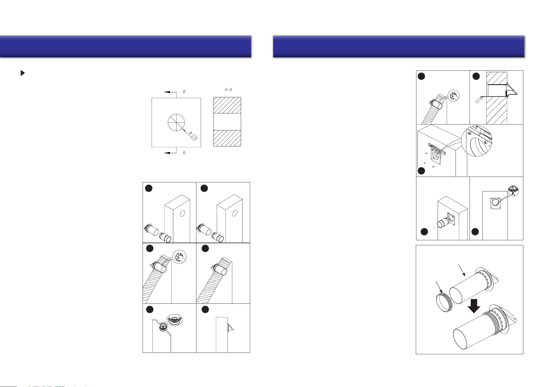
VENTILATOR INSTALLATION
1. Drill a 170 mm (6”-3/4) round hole in the wall.
The hole size is shown below.
1
3
2
4-1
4-34-2
Assemble the inner duct and outer duct
together to adapt to the thickness of the
wall, then take out the inner duct and put
the outer duct into the wall hole.
After that, grasp the bracket to spin the
outer duct forward and backward, left and
right to make the air inlet/outlet correctly
orients downward according to the indicator
of the external ventilation hood.
(The outer duct cannot be longer than the
wall thickness, and the extra parts can be
removed. For installation of outer ducts
with/without accessories, please refer
to step 5).
3. If there are no scenarios in the environment
of the installation where rainwater can
directly spill into the ERV, you can insert
the accessory silicone seal from the
accessory bag into the outer air duct, and
then install the duct into the wall.
It can be sealed with the wall, whereby the
duct plays the role of waterproofing.
In this case, it will be possible to proceed
without carrying out Step 2, and there is
no need to use polyurethane glue to seal the
space between the wall and the duct.
(The silicone seal installation position is
flexible, it simply needs to be inserted into
the air outside the duct at a specific depth).
Slightly pull the duct
if it is stuck in the wall.
Pull the duct further in if
it is loose.
Please note
that the plastic
block on the
metal plate
should be
on top of the
Silicone Sealing Ring
Outer Duct
Indoor
Outdoor
Plug the inner air duct into
the hole and turn the wire
inside the inner air duct face
down, the direction should
1
3
4 5
2
be the
same
as the
mark of
the outer
duct.
2. Pull the mobile bracket into the outer duct
back into place so that the silicone ring on
the outside of the outer duct is tight against
the outer wall.
Fill the space between the wall and the
outer duct with the polyurethane glue provided
in the kit before attaching the back cover
mounting plate, and then wait for the glue to dry.
Then install the back cover mounting plate,
align the round hole of the back cover of the
mounting plate with the round hole on the
wall, and measure the level of the
mounting plate with a level ruler to
ensure that the mounting plate installation
is horizontal. Then mark the hole, punch
in the expansion rubber grain, and align
the mounting plate with the hole and
secure it with a screw.
round hole when installing the
back cover mounting plate.
Installation
11 12
Operation
1
3
4
2
CONNECTION TO POWER
DISCONNECT THE VENTILATOR FROM THE POWER SUPPLY PRIOR
TO PERFORMING ANY ELECTRIC INSTALLATION OPERATIONS.
THE VENTILATOR IS DESIGNED FOR CONNECTION TO 1-PHASE
AC100-240V/50-60 HZ POWER SUPPLY.
CONNECT THE VENTILATOR TO THE SOCKET DIRECTLY.
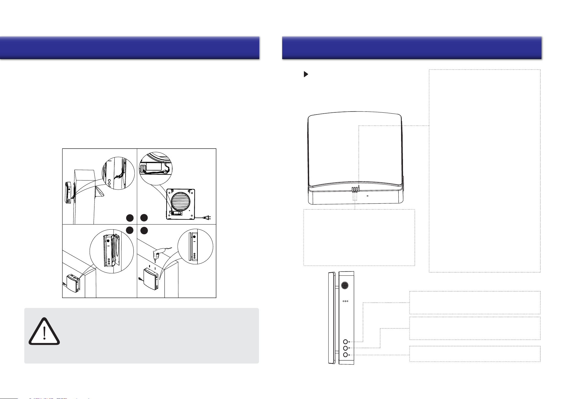
4. Install the main unit on the indoor surface wall. Connect the adapter wire from the back of the
main unit to the wiring of the fan and temperature sensor exposed in the inner duct, and tidy
the wiring. Then align and install the main unit with the protruding plastic and metal parts on
the back cover plate (There are corresponding concave holes on the rear of the main unit).
The strong magnet equipped on the back of the main unit will automatically attract the
wall mounting plate (After installation is complete, check if there is a large gap between the
main unit and the mounting plate. If so, it means that the wires in the main unit are not placed
properly. Please remove the main unit and reinstall it). Finally, turn the two small M3 screws
(included in the kit) into the hole at the top of the main unit (shown in Figure 4), and the
installation is complete.
FUNCTION DESCRIPTION
Function Light (RGB-LED)
Status Light (RGB-LED)
ON Status
OFF Status (coordinated with the buttons)
1. Function light indicates the fan speed.
There are 3 speeds in total.
2. The green light indicates air supply.
3. The red light indicates air exhaust.
4. The blue shows indicates regeneration mode,
which switches on after 75 seconds of cyclic
operation between air supply and air exhaust.
Description Of The Master Unit
Master Unit Front
1. Blue light flashes slowly: Indicates the device
role is set as the master in pairing mode.
2. Green light flashes slowly: Indicates the role
of the device is set as a slave in pairing mode.
3. Red light flashes slowly: Indicates that the
device is in Wi-Fi connection mode.
MODE
ON State: You can switch the working mode of the device
(supply mode, exhaust mode, regeneration mode).
FAN SPEED
ON State: You can switch the fan speed of the device.
There are 3 speeds in total.
ON/OFF
Control the device to switch between an ON/OFF state.
Master Unit
Side
1. Blue light is on: Pairing mode is activated,
and the linkage communication function is
active between the master and slave units.
2. Green light is on: IoT function is enabled,
Wi-Fi is connected successfully, and user is
able to control the device from the phone.
3. Red light is on: Filter cleaning alarm to
remind user that it is time to clean or replace
the filter within the inner duct.
4. Purple light is on: Indicates the master role
in master-slave online mode, the master
loT networking function is enabled, and the
unit can be controlled by the user’s phone.
5. Green light flashes slowly: Automatic
ventilation function is on and running.
6. Blue light flashes slowly: Free-cooling
function is on and running.
7. Red light flashes three times: Indicates that
the filter cleaning is complete and the
cleaning time has been reset.
13
Operation
14
Operation
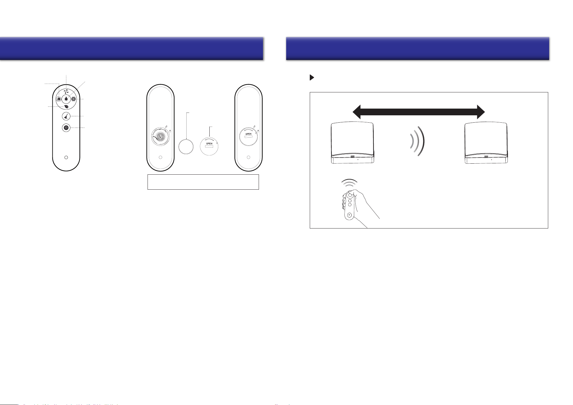
Remote Controller
This remote control uses infrared signals.
1. Before using the remote control, insert the battery into the remote control and close the
battery cover tightly.
2. After inserting the battery, screw the battery cover clockwise as shown until the cover triangle arrow
indicates the locking pattern, which means it is locked (Do not tighten the cover with your bare
hands to avoid potential injury).
3. To remove the battery, turn the battery cover counterclockwise as shown in the picture until the
triangle arrow of the cover indicates the unlocking pattern. Once loose, the battery can be removed.
4. Please store the remote control properly to prevent children from attempting to swallow batteries and/or
other potential accidents.
1. Fan Speed: Switches the fan speed of the device. There are 3 speeds in total.
2. Working Mode: Switches the working mode of the device (supply mode, exhaust mode, regeneration mode).
3. Negative Ion ON/OFF: Negative ion generator power socket work switch, (when the negative ion function
is turned on, the device supplies air with the power supply. Negative ion generator
is purchased separately and added on).
4. Indicator Light: Control indicator light for On and Off.
5. Fan Boost Mode: Sets the fan into fan boost mode, where the fan runs at maximum power if there is no
other setting. The devi
ce runs this mode for 30 minutes before exiting automatically.
6. Filter Reset: After replacing the filter of the inner air duct, press and hold the button for 5 seconds, the device
red light flashes three times, and the filer cleaning time is reset. (Reset time default: 720 hours)
7. ON/OFF: Turn ON/OFF the device.
Button cell CR2025
Cover
Please insert the button cell (prepared by user)
before attempting to use the controller.
Remote Control
Fan Speed
Indicator Light
ON/OFF
Fan Boost
Mode
Filter Reset
Negative Ion
ON/OFF
Working
Mode
ON/OFF
PAIRING SYNCHRONIZATION FUNCTION
Master Unit Slave Unit
The suggested maximum distance is 50 feet
• The maximum linear unobstructed communication signal distance between master and slave is 50 feet.
• The signal from the master and slave can pass through an up to 7 inch thick brick wall.
Note:
When controlling the device via remote control,
point the remote control at the device head-on.
1. Without setting a master/slave role, one remote control can control one or more devices.
2. After setting the master/slave role, the current use of the remote control can only control the master,
and the master forwards the synchronization signal to the slave (the slave does not receive the remote
control signal), so that the slave mode is synchronized with the master.
(The master can only control one slave alone).
3. In regeneration mode, the operation direction of the slave fan is opposite to that of the master,
and the direction of the slave fan in other modes is the same as that of the master.
1615
Operation Operation
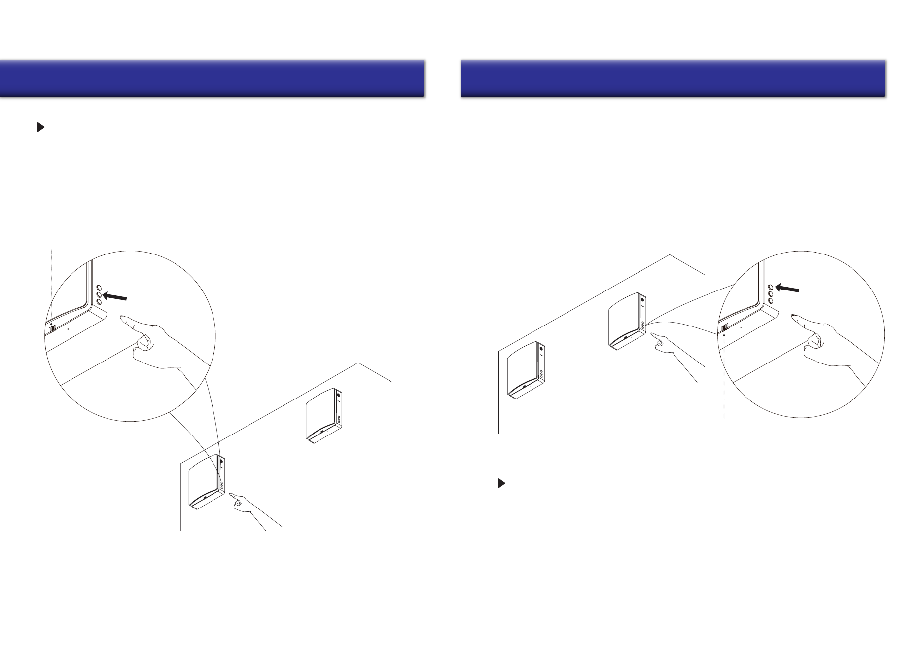
MASTER-SLAVE UNIT SETTINGS
MASTER-SLAVE RESET AND CANCELLATION
Master unit
Slave unit
The right side blue light will start slowly flashing
Master Unit Settings
Connect the device to power. In the OFF state, as shown in the figure, press and hold the fan
speed button of the unit for 5 seconds, and the status indicator blue light flashes slowly.
Once done, the device enters master-slave linkage mode, and is set to the master role.
Slave Unit Settings
Master unit
Slave unit
The right side green light will start slowly flashing
1. Connect the device to power. In the OFF state, as shown in the figure, press and hold the mode
button of the device for 5 seconds, and the status indicator green light will start flashing slowly.
Once done, the device enters master-slave linkage mode, and the unit is set to the slave role.
2. During the master and slave set pairing mode, it must be carried out at the same time
inside a limited time (within 1 minute). The devices should be as close as possible. The devices
will be automatically connected.
3. The status light of the paired devices will change to blue light ON to indicate that the
master-slave pairing is successful.
4. If the master-slave pairing fails, the status lights on the devices will flash for one
minute and before the lights turn off automatically.
Connect the device to power. In the OFF state, long press the fan speed button of the
linked device for 5 seconds, and the device status indicator blue light will start flashing slowly.
At this time, the linked device enters master-slave linkage mode, and the device defaults to
the master role. It should be carried out at the same time inside a limited time (within 1 minute).
Wait for the status indicator lights to come off automatically, whereby the device disconnects from
the slave to break off the master-slave pairing automatically. At this stage, the device is reset
and restored to the factory state, without any role definition.
17
Wi-Fi Connection Wi-Fi Connection
18
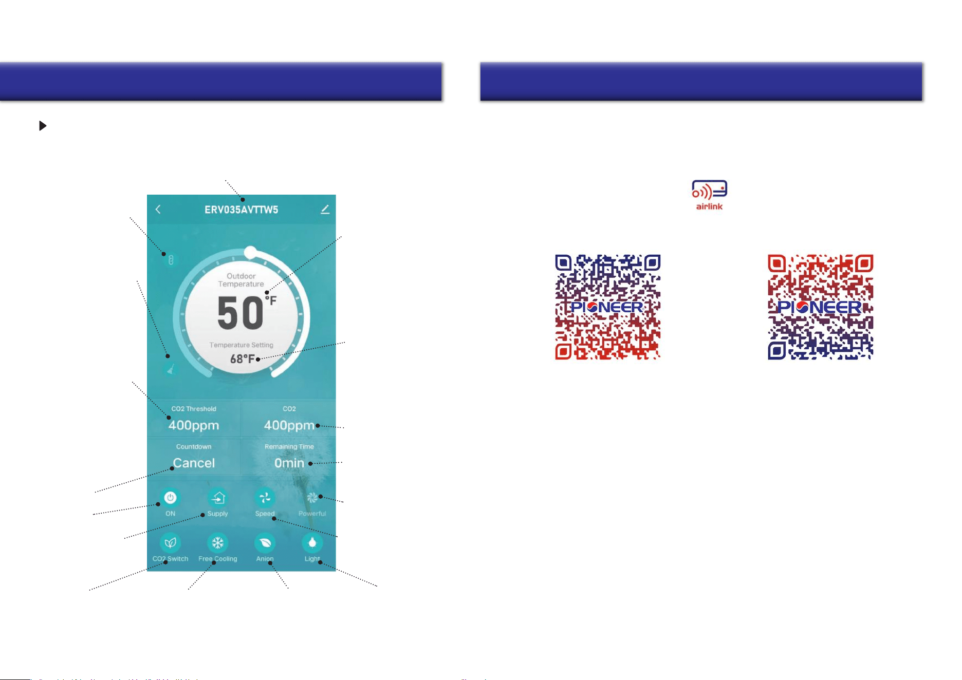
ERV name: The app can connect multiple devices. Each device will have a
dierent name, and users can change the device name freely
Indicator lights
ON/OFF
Negative ion
function ON/OFF
Free cooling
function ON/OFF
function ON/OFF
CO
2
concentration
Outdoor temperature:
Displays the outdoor
temperature when the
unit is ON and operating
in supply or regeneration
mode. In exhaust mode,
the outdoor temperature is
not sensed and displayed
Free cooling temperature
setting: When the outdoor
air is comfortable, it will
work in supply mode to
introduce fresh air without
heat recovery, which is called
free cooling. Users can set
the outdoor temperature
to enable this function.
The setting range is 50°F to
84°F
Real-time indoor CO
2
concentration
Remaining time after the
scheduled shutdown
Fan boost function: The
unit will supply/exhaust at
the highest speed.
Fan speed: Total 3 speeds
Pairing icon: After the
devices are paired, the
icon is displayed, and the
slave is oine and can’t be
controlled
Filter alarm: It reminds the
user to clean or replace
the filters. Icon disappears
after reset
CO
2
concentration setting:
When the CO
2
sensor is
connected, if the indoor
CO
2
concentration exceeds
the set value while the
unit is ope
rating in
regeneration mode, the
unit will enter the supply
mode to introduce fresh
air to dilute the CO
2
concentration until the CO
2
concentration is lower than
the set value. The unit then
returns to the previous
mode. It can be set from
400 to 2000ppm
12-hours timer
Power ON/OFF
Operating mode: (supply
mode, exhaust mode,
regeneration mode)
IOT NETWORKING FUNCTIONS
CO
2
Version
Installation of “Pioneer Airlink” smartphone application
Search for “Pioneer Airlink” in the Google Play Store (for Android users) or the App Store (for iOS users).
Note that a 2.4GHz Wi-Fi connection is needed to use the Wi-Fi control feature.
Or, scan the below QR code to download the app from the respective app store.
Wireless Control App Setup Process
1. Registration and Log-In:
If you do not already have a “Pioneer Airlink” account, please create and account and log-in
by following the below steps:
2. Adding a New Device:
Download iOS App
Download Android App
i. Approve the “User Agreement” and “Privacy Policy” when they appear by tapping “I Agree”.
ii. Tap the “Sign Up” button, choose your country, and enter your mobile number/e-mail to register,
tick “I Agree” on “User Agreement and Privacy Policy”, then tap the “Get Verification Code” button.
The phone or e-mail that you’re registering will receive a registration verification code.
iii. Enter the verification code and select a password. You will then either land on the homepage of
the App, or back to the login interface to log into the app, by using the account you just created.
i. Confirm that your phone is connected to Wi-Fi (2.4GHz networks only, 5Ghz will not work).
Tap the “+” at the top-right corner of the homepage, to enter the device selection page.
ii. Once you’ve entered this page, head to your Pioneer ERV system and long press “On/Off”
buttons when the ventilator is turned ON, until the Wi-Fi symbol on the display screen flashes.
(Fast flashing indicates Wi-Fi connection, slow flashing refers to hotspot network.)
Wi-Fi Connection
19 20
Wi-Fi Connection
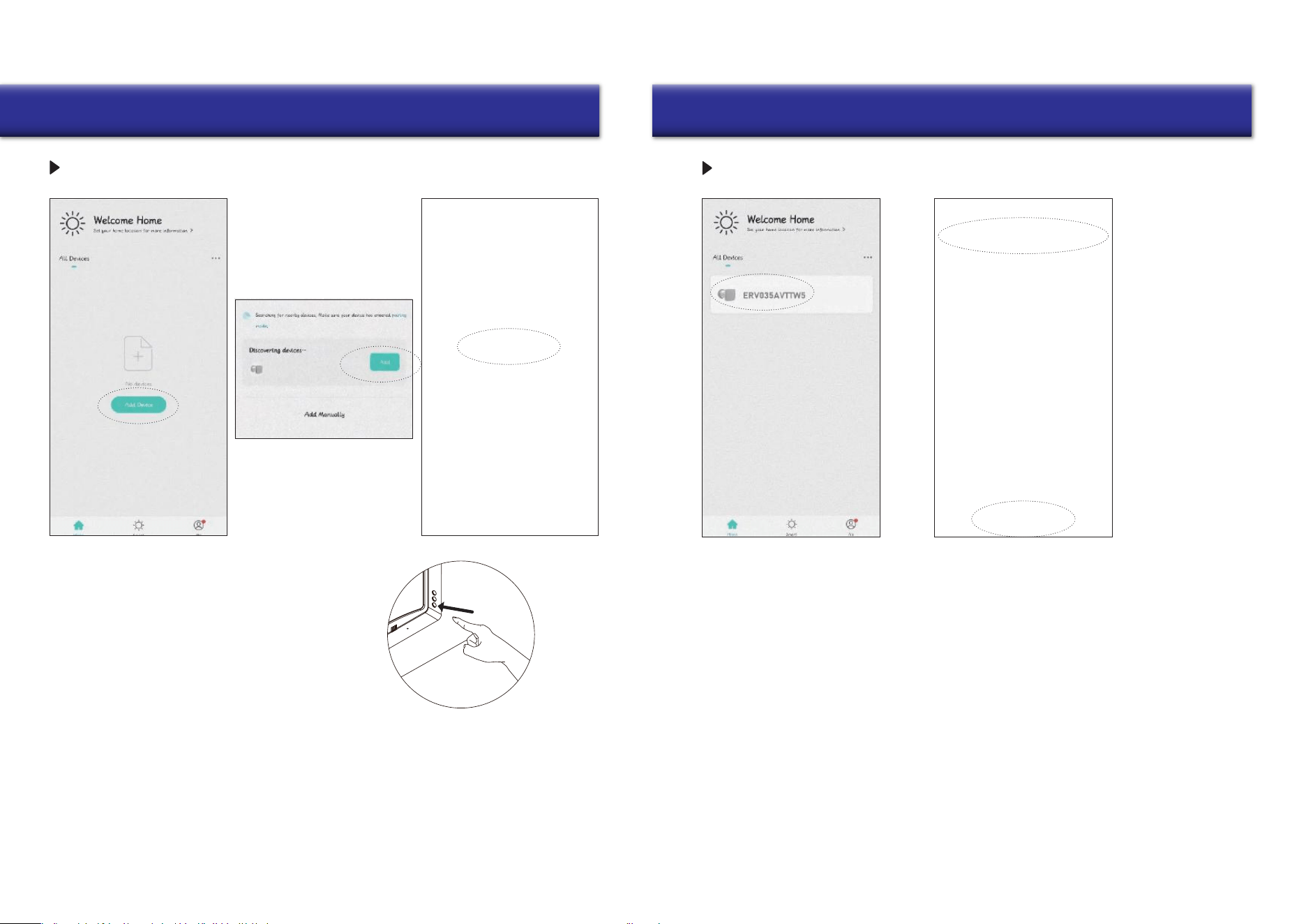
IOT NETWORKING OPERATION STEPS
3. Open the downloaded Pioneer Airlink app,
enter the operation page, click the add
device box, and search for devices.
4. At this time the app receives the signal from
the device, then proceeds to add the device for
network connection.
1. Before enabling IoT networking operation,
please connect your cell phone to your home
router Wi-Fi, turn on the Bluetooth function of
your cell phone, and ensure that the device
and cell phone are within the Wi-Fi signal
coverage (make sure the router Wi-Fi is
enabled for 2.4G network).
2. When the device is powered on, in the OFF
state, long press the ON/OFF button of any
device for 5 seconds, the device status
indicator will flash red slowly, then the device
will enter the Wi-Fi pairing state, and the
cell phone will be available for operation and
connection.
WI-FI RESET AND CANCELLATION
Remove the device from
the app as follows:
5. Click Add Device to find the
Wi-Fi signal of your home
router, and make sure the
Wi-Fi name on the app is the
same as the name of the Wi-Fi
connection to your phone, then
log in with the Wi-Fi password.
6. After successful Wi-Fi connection,
the device will be connected to the
network, and after the connection is
completed, you can enter the operation
page to operate.
1. Return to the app operation connection page, long
press the device that needs to be disconnected,
then the option to remove the device will appear
at the bottom.
2. Click on the remove device option and confirm to
successfully disconnect the device from Wi-Fi.
21
Maintenance
22
Maintenance
Prefilter
Ceramic energy regenerator
(recommended to be
cleaned 4 times a year)
Ceramic energy
regenerator cleaning:
This part can be rinsed
directly with water.
Once rinsing is done,
place it in a sunlit
location and wait until
it fully dries.
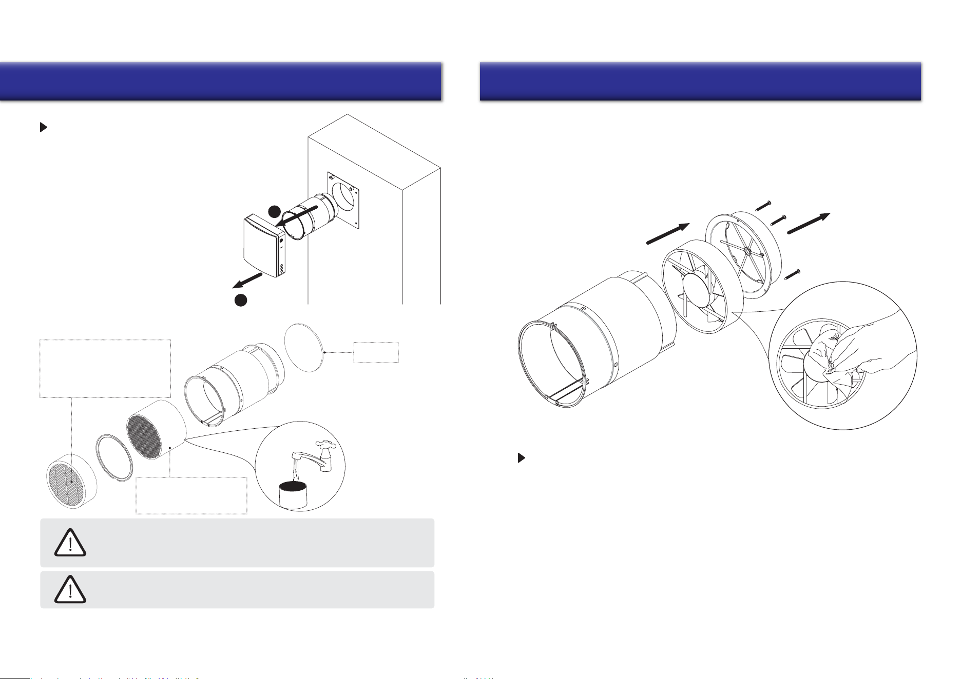
MAINTENANCE
Loosen the screws on the top of the main unit.
After unplugging the connecting wires of the
main unit and the inner duct, remove the main
unit and the inner duct from the wall separately.
Pull the cord at both sides of the ceramic
energy regenerator, and F7 medium filter
and remove both the F7 filter and ceramic
energy regenerator from the inner duct.
1
2
•
The ceramic energy regenerator should be
cleaned at least 4 times a year.
•
The F7 filter should be replaced regularly.
It’s recommended to change it after each
time the filter alert displays.
(The ceramic energy regenerator is fragile,
it should be carefully removed to avoid damage.)
The F7 filter is not washable and
should be vacuumed or replaced
when dirty. Please contact your
distributor/vendor to purchase
replacement filters.
Even regular technical maintenance may not completely prevent dirt accumulation
on the regenerator assemblies.
Treat the exchanger with regular cleaning to ensure high heat exchange efficiency.
Clean the exchanger using a vacuum cleaner at least once a year.
Clean the prefilter at least 4 times a year. The user can wash or vacuum the prefilter.
Note that after washing the prefilter, it should be dried and reinstalled in the air duct.
The lifetime of the prefilter is about 3 years. Purchase replacement filters from vendor.
STORAGE AND TRANSPORTATION GUIDELINES
Fan Maintenance (Once Per Year)
Remove the secured bracket from within the inner duct and take out the fan.
Clean the impeller blades. Use a soft brush, doth, or a vacuum cleaner to clean the impeller. Do not use
water, abrasive detergents, solvents, or sharp objects. The impeller blades must be cleaned once a year.
Store the ventilator inside the manufacturer’s original packing box in a cool, dry place.
The storage environment must be free of any aggressive vapors and chemical mixtures that
may cause corrosion, insulation, and sealing deformation. Use lifting equipment for handling
and storage operations to prevent ventilator from damage as a consequence of failing or
excessive vibration. Fulfill the handling requirements relevant to the applicable freight type.
Transportation via any type of vehicle is allowed, provided that the ventilator is protected against
mechanical and weather damage.
Take care to avoid any mechanical shocks and sharp ends during handling operations.
23
Troubleshooting Contact Information
is a registered trademark of Parker Davis HVAC
International, Inc.
Parker Davis HVAC International, Inc.
3250 NW 107 Avenue, Doral, FL 33172 - USA
Tel : (305) 513-4488
Fax : (305) 513-4499
E-mail : [email protected]
Website : www.pdhvac.com
Pioneer product line, parts, and supplies are
available online for convenient ordering at:
www.highseer.com
www.pioneerminisplit.com
Scan the below code to visit our support page
where you can find more installation materials:
Copyright 2024, Parker Davis HVAC International, Inc., All rights reserved.
The design and specifications of this product are subject to change without prior notice
as development continues. Consult with the sales agency or manufacturer for details.
Refer to the equipment nameplate for all other applicable specifications.
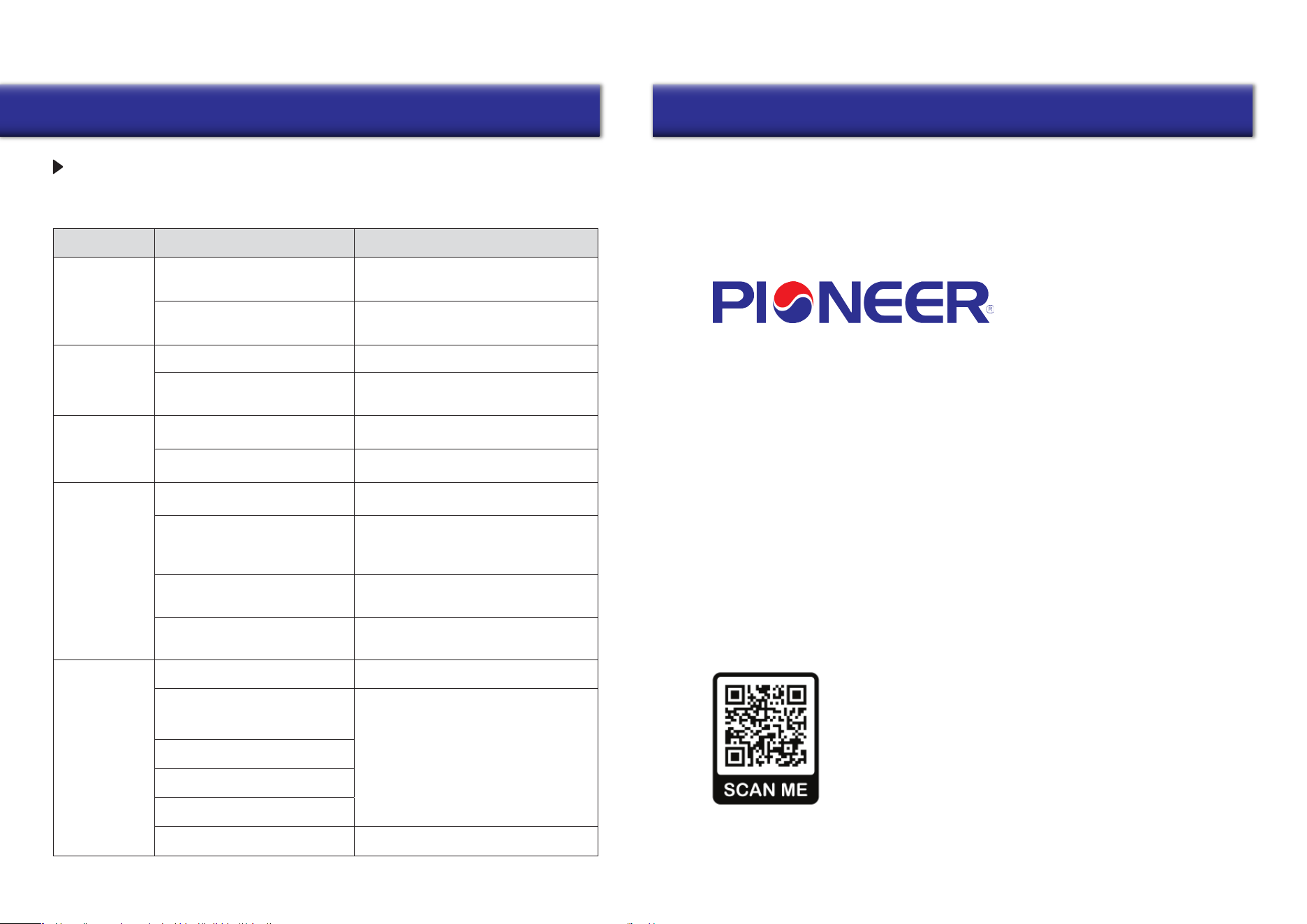
Users can often perform basic self-troubleshooting using the below chart, in the event
of any faults or malfunctions.
Fault
Possible Causes Troubleshooting
The fan does not
start up
No power supply
The motor is stuck, or the impellers
are clogged
Make sure that the ventilator is properly
connected to the power and make any
corrections, if necessary
Low airflow
Low fan speed setting Set a higher speed
Turn the ventilator off. Troubleshoot the motor
jam and the impeller blockage. Clean the blades.
Restart the ventilator.
Filter, fan, or exchanger are dirty
Noise/vibration
The impeller is dirty Clean the impeller
Clean or replace the filter, and clean the fan
and the exchanger. For exchanger and filter
maintenance, see page 22.
Loose connection of the ventilator
casing or the ventilation hood
Master-Slave
pairing failed
Tighten the screws of the ventilator or the
outer hood
Master-Slave units set by a different
controller
According to the manual, use the same remote
controller for the Master-Slave units settings
The ventilator is installed where it is
surrounded by a lot of metal/ there
are many sources of interference
Other
The distance between Master and
Slave units is too long/the wall
between them is too thick
Excessive metal structures and interference
sources around will weaken the wireless
signal. Remove these sources of signal
interference or change the installation location
Please change the installation location
according to the distances shown in the manual
Wi-Fi connection
failed
Please reset the master-slave setting (press
and hold the RESET button for ten seconds),
and set it again after a period of power off
The mobile phone is connected to the
WiFi 5G network
Please switch to the 2.4G frequency/network
to connect.
Please set up the Wi-Fi router correctly
Wrong connection to public WiFi (such
as Wi-Fi in shopping malls, hotels, etc.)
User must be registered and logged in
The router has not yet set up an
account and password
The router is set to a higher security
level
Bluetooth on the mobile phone is off
You have exceeded the limit of devices
that can be connected to the router.
Enable Bluetooth on the mobile phone to
improve the success rate of networking
TROUBLESHOOTING