ALTA
®
900 MHZ RECHARGEABLE
WATER DETECTION DISC
USER MANUAL
Remote Monitoring for Business
By
CAUTION SYMBOL EXPLANATION
The following caution symbol appears on the product. This symbol indicates caution and a potential
risk of danger. Carefully read the warning attached with each symbol.
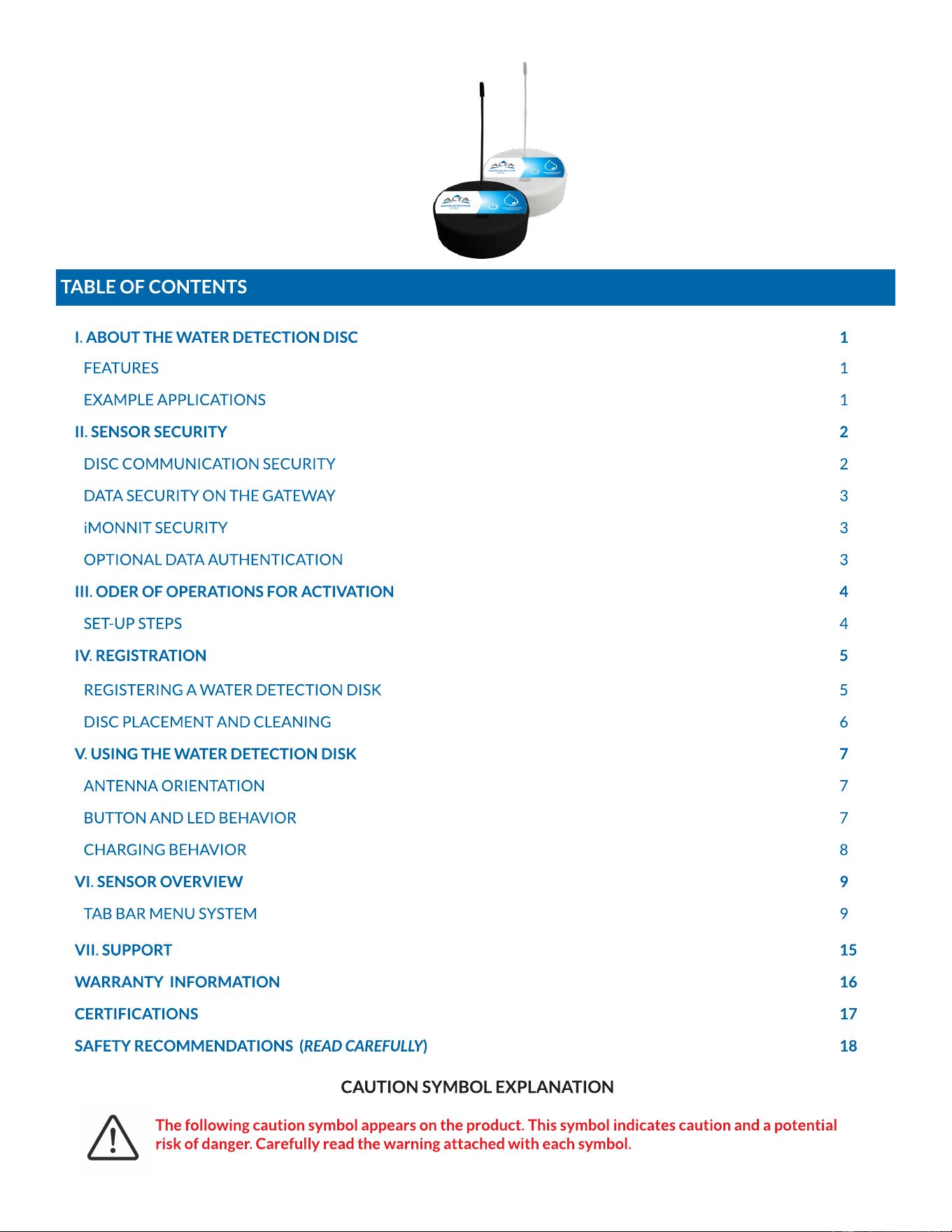
TABLE OF CONTENTS
I. ABOUT THE WATER DETECTION DISC 1
FEATURES 1
EXAMPLE APPLICATIONS 1
II. SENSOR SECURITY 2
DISC COMMUNICATION SECURITY 2
DATA SECURITY ON THE GATEWAY 3
iMONNIT SECURITY 3
OPTIONAL DATA AUTHENTICATION 3
III. ODER OF OPERATIONS FOR ACTIVATION 4
SET-UP STEPS 4
IV. REGISTRATION 5
REGISTERING A WATER DETECTION DISK 5
DISC PLACEMENT AND CLEANING 6
V. USING THE WATER DETECTION DISK 7
ANTENNA ORIENTATION 7
BUTTON AND LED BEHAVIOR 7
CHARGING BEHAVIOR 8
VI. SENSOR OVERVIEW 9
TAB BAR MENU SYSTEM 9
VII. SUPPORT 15
WARRANTY INFORMATION 16
CERTIFICATIONS 17
SAFETY RECOMMENDATIONS (READ CAREFULLY) 18
PAGE 1
I. ABOUT THE WATER DETECTION DISK
GENERAL DESCRIPTION
The ALTA
®
Wireless Water Detection Disk detects the presence or non-presence of water. Convenient, water-tight-disk
design allows the sensor to be placed anywhere needed whether dry or wet. Note that water levels must be ~ 3mm deep to
trigger detection.
The ALTA Wireless Water Detection Disk detects when water is present by completing the circuit between the two probe
points on the bottom of the disk. When water is present, the sensor will immediately turn on the radio and transmit the data
to the wireless gateway and the iMonnit
®
Online Sensor Monitoring and Notification System, allowing the user to
immediately receive an SMS text, or email alert. The sensor can be configured to detect both the presence and non-presence.
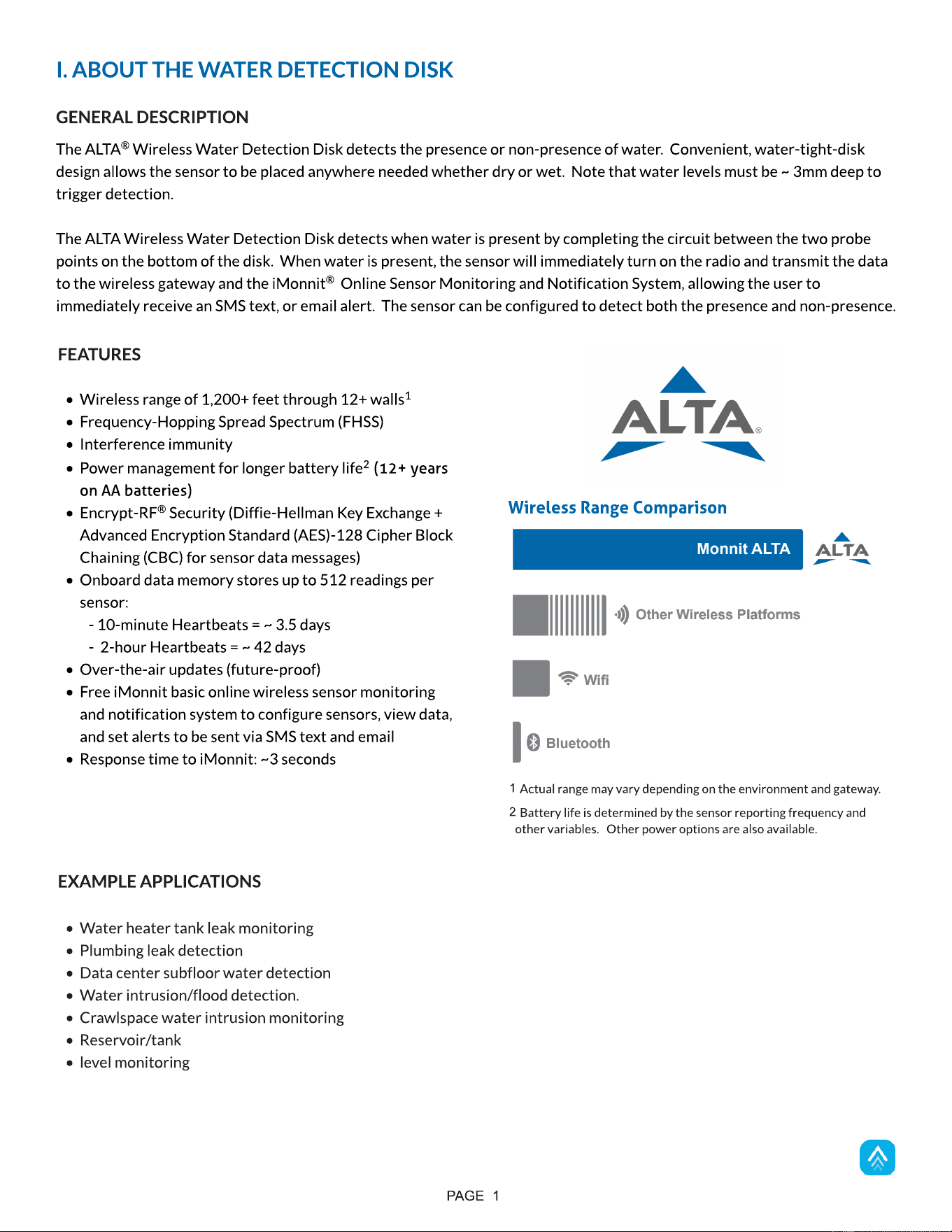
- Wireless range of 1,200+ feet through 12+ walls
1
- Frequency-Hopping Spread Spectrum (FHSS)
- Interference immunity
- Power management for longer battery life
2
(12+ years
on AA batteries)
- Encrypt-RF
®
Security (Diffie-Hellman Key Exchange +
Advanced Encryption Standard (AES)-128 Cipher Block
Chaining (CBC) for sensor data messages)
- Onboard data memory stores up to 512 readings per
sensor:
- 10-minute Heartbeats = ~ 3.5 days
- 2-hour Heartbeats = ~ 42 days
- Over-the-air updates (future-proof)
- Free iMonnit basic online wireless sensor monitoring
and notification system to configure sensors, view data,
and set alerts to be sent via SMS text and email
- Response time to iMonnit: ~3 seconds
1
Actual range may vary depending on the environment and gateway.
2
Battery life is determined by the sensor reporting frequency and
other variables. Other power options are also available.
FEATURES
Wireless Range Comparison
EXAMPLE APPLICATIONS
- Water heater tank leak monitoring
- Plumbing leak detection
- Data center subfloor water detection
- Water intrusion/flood detection.
- Crawlspace water intrusion monitoring
- Reservoir/tank
- level monitoring
II. SENSOR SECURITY
The ALTA Wireless Water Detection Disk has been designed and built to securely manage data from sensors monitoring your
environment and equipment. Hacking from botnets are in the headlines, Monnit
®
Corporation has taken extreme measures
to ensure your data security is handled with the utmost care and attention to detail. The same methods utilized by financial
institutions to transmit data are also used in Monnit security infrastructure. Security features of the gateway include tamper
proof network interfaces, data encryption, and bank-grade security.
Monnit?s proprietary sensor protocol uses low transmit power and specialized radio equipment to transmit application data.
Wireless devices listening on open communication protocols cannot eavesdrop on sensors. Packet level encryption and
verification is key to ensuring traffic isn?t altered between sensors and gateways. Paired with a best-in-class range and
power consumption protocol, all data is transmitted securely from your devices. Thereby ensuring a smooth, worry-free,
experience.
PAGE 2
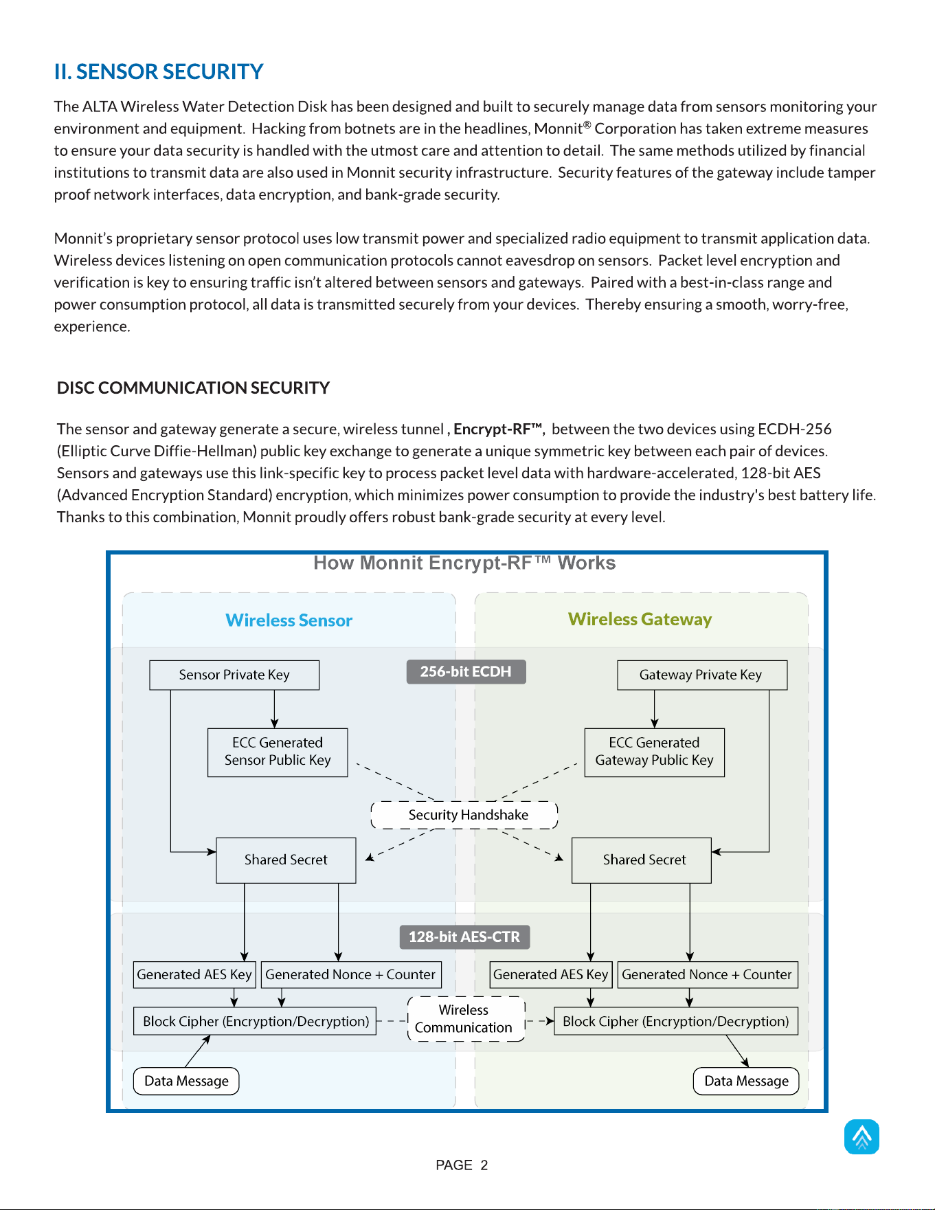
DISC COMMUNICATION SECURITY
The sensor and gateway generate a secure, wireless tunnel , Encrypt-RF?, between the two devices using ECDH-256
(Elliptic Curve Diffie-Hellman) public key exchange to generate a unique symmetric key between each pair of devices.
Sensors and gateways use this link-specific key to process packet level data with hardware-accelerated, 128-bit AES
(Advanced Encryption Standard) encryption, which minimizes power consumption to provide the industry's best battery life.
Thanks to this combination, Monnit proudly offers robust bank-grade security at every level.
For more information on Ethernet Gateway Security, visit
https://monnit.blob.core.windows.net/site/documents/other/ethernet-gateway-security-brief.pdf
SensorPrints
TM
is the industry's only end-to-end Internet of Things (IoT) data authentication platform for low-power
wireless sensors. SensorPrints authenticates data by issuing a unique fingerprint for each device within the IoT. Data is
secured from the point of generation to the point of consumption. Easy to install and use, SensorPrints is the definitive IoT
security solution for any enterprise.
SensorPrints authenticates data at both the point of generation and consumption, creating trust between the sensor and
server levels. Implementing 256-bit SHA 3 authentication, SensorPrints creates a fingerprint for a Monnit Wireless Sensor
that contains an authenticated sensor message. When data is transmitted from the sensor, it is accompanied by a generated
authentication token. Upon receipt by the application, the token is evaluated via a cryptographic hash function against a
unique per-sensor secret key. This step provides unprecedented full-coverage security for any Monnit user wishing to secure
their IoT devices and data.
Click here for more information on SensorPrints.
OPTIONAL DATA AUTHENTICATION
PAGE 3
iMONNIT SECURITY
iMonnit is the online software and central hub for configuring your device settings. All data is secured on dedicated servers
operating Microsoft SQL Server. Access is granted through the iMonnit user interface, or an Application Programming
Interface (API) safeguarded by 256-bit Transport Layer Security (TLS 1.2) encryption. TLS is a blanket of protection that
encrypts all data exchanged between iMonnit and you. The same encryption is available to you whether you are a basic user
or a premiere user of iMonnit. You can rest assured that your data is safe with iMonnit.
DATA SECURITY ON THE GATEWAY
The ALTA gateways are designed to prevent prying eyes from accessing the data that is stored on the sensors. Gateways do
not run on an off-the-shelf, multi-function OS (operating system). Instead, they run a purpose-specific, real-time, embedded
state machine that cannot be hacked to run malicious processes. There are also no active interface listeners that can be used
to gain access to the device over the network. The fortified gateway secures your data from attackers and secures the
gateway from becoming a relay for malicious programs.
SET-UP STEPS
PAGE 4
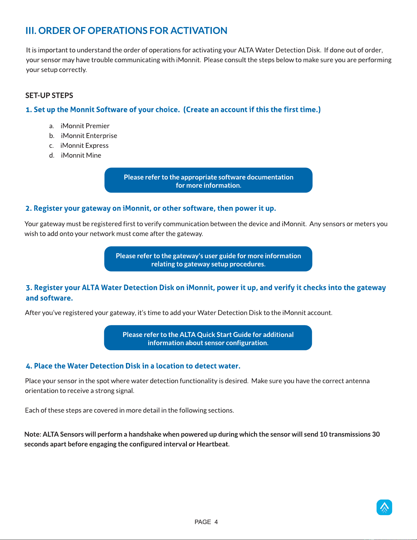
It is important to understand the order of operations for activating your ALTA Water Detection Disk. If done out of order,
your sensor may have trouble communicating with iMonnit. Please consult the steps below to make sure you are performing
your setup correctly.
III. ORDER OF OPERATIONS FOR ACTIVATION
Your gateway must be registered first to verify communication between the device and iMonnit. Any sensors or meters you
wish to add onto your network must come after the gateway.
2. Register your gateway on iMonnit, or other software, then power it up.
After you?ve registered your gateway, it?s time to add your Water Detection Disk to the iMonnit account.
3. Register your ALTA Water Detection Disk on iMonnit, power it up, and verify it checks into the gateway
and software.
Please refer to the ALTA Quick Start Guide for additional
information about sensor configuration.
Please refer to the gateway's user guide for more information
relating to gateway setup procedures.
a. iMonnit Premier
b. iMonnit Enterprise
c. iMonnit Express
d. iMonnit Mine
1. Set up the Monnit Software of your choice. (Create an account if this the first time.)
Please refer to the appropriate software documentation
for more information.
Note: ALTA Sensors will perform a handshake when powered up during which the sensor will send 10 transmissions 30
seconds apart before engaging the configured interval or Heartbeat.
Place your sensor in the spot where water detection functionality is desired. Make sure you have the correct antenna
orientation to receive a strong signal.
Each of these steps are covered in more detail in the following sections.
4. Place the Water Detection Disk in a location to detect water.
PAGE 5
REGISTERING A WATER DETECTION DISK
If this is your first time using the iMonnit online portal, you will need to create a new account. If you have already created an
account, start by logging in. For instructions on how to register for an iMonnit account, please consult the iMonnit User
Guide viewable at monnit.com/support/documentation.
IV. REGISTRATION
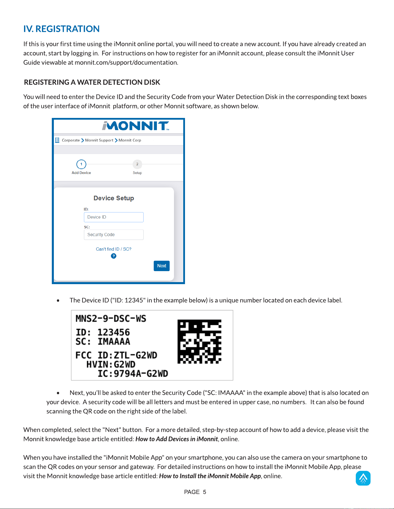
You will need to enter the Device ID and the Security Code from your Water Detection Disk in the corresponding text boxes
of the user interface of iMonnit platform, or other Monnit software, as shown below.
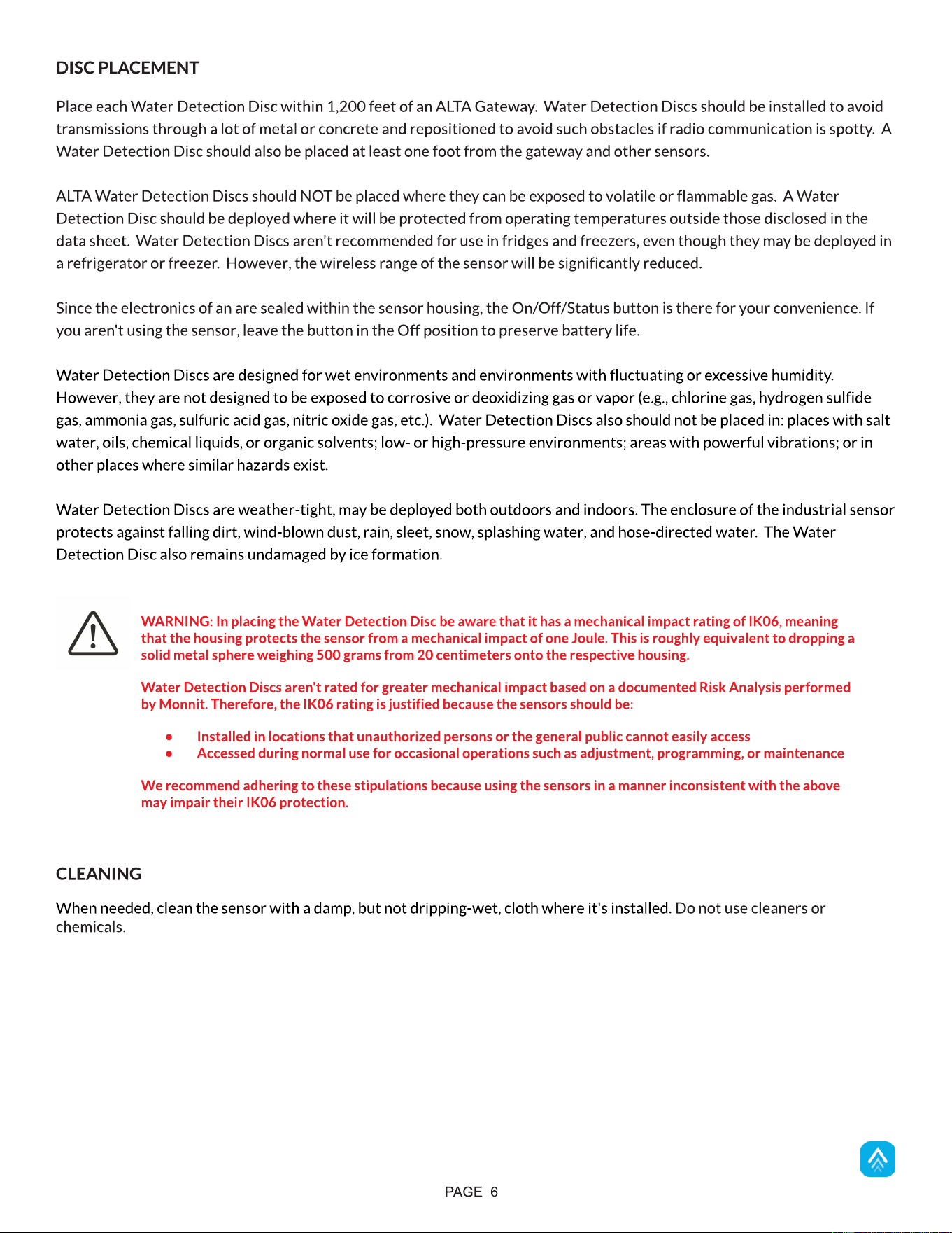
- The Device ID ("ID: 12345" in the example below) is a unique number located on each device label.
- Next, you?ll be asked to enter the Security Code ("SC: IMAAAA" in the example above) that is also located on
your device. A security code will be all letters and must be entered in upper case, no numbers. It can also be found
scanning the QR code on the right side of the label.
When completed, select the "Next" button. For a more detailed, step-by-step account of how to add a device, please visit the
Monnit knowledge base article entitled: How to Add Devices in iMonnit, online.
When you have installed the "iMonnit Mobile App" on your smartphone, you can also use the camera on your smartphone to
scan the QR codes on your sensor and gateway. For detailed instructions on how to install the iMonnit Mobile App, please
visit the Monnit knowledge base article entitled: How to Install the iMonnit Mobile App, online.
DISC PLACEMENT
Place each Water Detection Disc within 1,200 feet of an ALTA Gateway. Water Detection Discs should be installed to avoid
transmissions through a lot of metal or concrete and repositioned to avoid such obstacles if radio communication is spotty. A
Water Detection Disc should also be placed at least one foot from the gateway and other sensors.
ALTA Water Detection Discs should NOT be placed where they can be exposed to volatile or flammable gas. A Water
Detection Disc should be deployed where it will be protected from operating temperatures outside those disclosed in the
data sheet. Water Detection Discs aren't recommended for use in fridges and freezers, even though they may be deployed in
a refrigerator or freezer. However, the wireless range of the sensor will be significantly reduced.
Since the electronics of an are sealed within the sensor housing, the On/Off/Status button is there for your convenience. If
you aren't using the sensor, leave the button in the Off position to preserve battery life.
Water Detection Discs are designed for wet environments and environments with fluctuating or excessive humidity.
However, they are not designed to be exposed to corrosive or deoxidizing gas or vapor (e.g., chlorine gas, hydrogen sulfide
gas, ammonia gas, sulfuric acid gas, nitric oxide gas, etc.). Water Detection Discs also should not be placed in: places with salt
water, oils, chemical liquids, or organic solvents; low- or high-pressure environments; areas with powerful vibrations; or in
other places where similar hazards exist.
Water Detection Discs are weather-tight, may be deployed both outdoors and indoors. The enclosure of the industrial sensor
protects against falling dirt, wind-blown dust, rain, sleet, snow, splashing water, and hose-directed water. The Water
Detection Disc also remains undamaged by ice formation.
WARNING: In placing the Water Detection Disc be aware that it has a mechanical impact rating of IK06, meaning
that the housing protects the sensor from a mechanical impact of one Joule. This is roughly equivalent to dropping a
solid metal sphere weighing 500 grams from 20 centimeters onto the respective housing.
Water Detection Discs aren't rated for greater mechanical impact based on a documented Risk Analysis performed
by Monnit. Therefore, the IK06 rating is justified because the sensors should be:
- Installed in locations that unauthorized persons or the general public cannot easily access
- Accessed during normal use for occasional operations such as adjustment, programming, or maintenance
We recommend adhering to these stipulations because using the sensors in a manner inconsistent with the above
may impair their IK06 protection.
PAGE 6
CLEANING
When needed, clean the sensor with a damp, but not dripping-wet, cloth where it's installed. Do not use cleaners or
chemicals.
PAGE 7
BUTTON AND LED BEHAVIOR
The Water Detection Disc has a button on the top that is used to control the behavior of the disc. This button can be used to
turn the disc on, turn the disc off and manually have the disc take and report a measurement.
V. USING THE WATER DETECTION DISC
Press and hold the button until the LED turns GREEN. When the
Device first turns on, the LED will flash GREEN four times and
then remain GREEN for one second. If the Water Detection Disc
is able to successfully connect to a gateway, the LED will flash
green two times. If the disc is unable to connect to a gateway
within 25 seconds, the LED will flash RED two times.
Turning the Disc ON
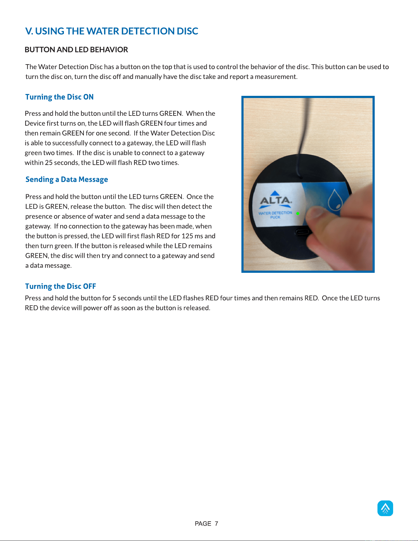
Press and hold the button until the LED turns GREEN. Once the
LED is GREEN, release the button. The disc will then detect the
presence or absence of water and send a data message to the
gateway. If no connection to the gateway has been made, when
the button is pressed, the LED will first flash RED for 125 ms and
then turn green. If the button is released while the LED remains
GREEN, the disc will then try and connect to a gateway and send
a data message.
Sending a Data Message
Press and hold the button for 5 seconds until the LED flashes RED four times and then remains RED. Once the LED turns
RED the device will power off as soon as the button is released.
Turning the Disc OFF
PAGE 8
CHARGING BEHAVIOR
The Water Detect Disc contains a rechargeable battery. This battery can be recharged through the USB-C port on top of the
device. The Water Detection Disc has a 3.0-to-5.5 VDC input voltage operating range. When power is detected, the device
will automatically begin charging the battery. The LED behavior depends on the charge of the battery.
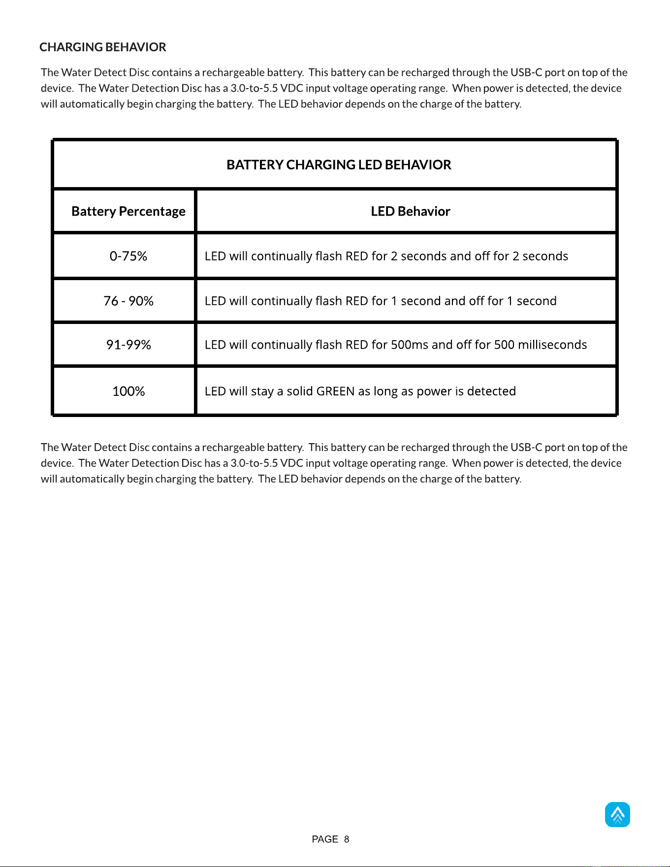
BATTERY CHARGING LED BEHAVIOR
Battery Percentage LED Behavior
0-75%
LED will continually flash RED for 2 seconds and off for 2 seconds
76 - 90%
LED will continually flash RED for 1 second and off for 1 second
91-99%
LED will continually flash RED for 500ms and off for 500 milliseconds
100%
LED will stay a solid GREEN as long as power is detected
VI. SENSOR OVERVIEW
PAGE 9
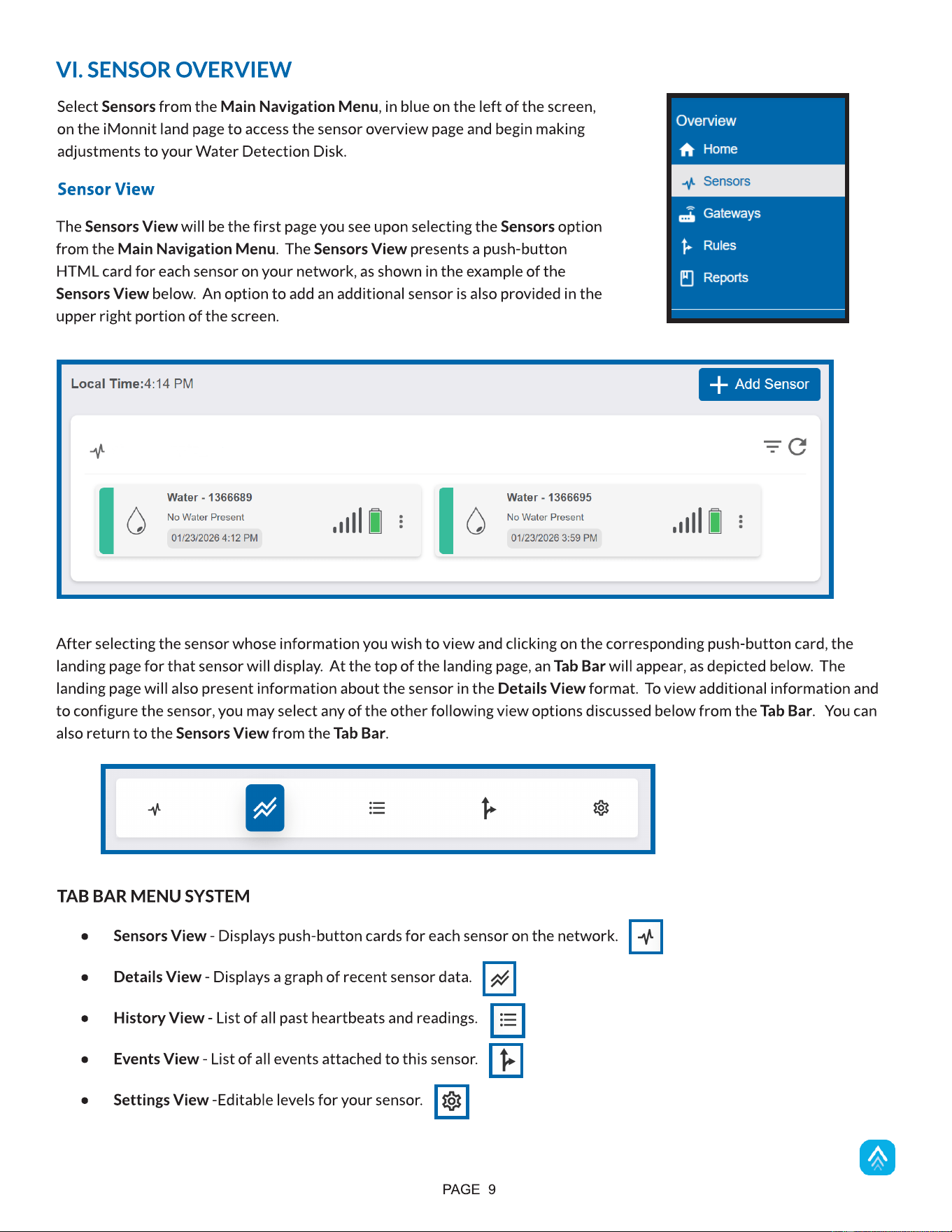
Select Sensors from the Main Navigation Menu, in blue on the left of the screen,
on the iMonnit land page to access the sensor overview page and begin making
adjustments to your Water Detection Disk.
TAB BAR MENU SYSTEM
- Sensors View - Displays push-button cards for each sensor on the network.
- Details View - Displays a graph of recent sensor data.
- History View - List of all past heartbeats and readings.
- Events View - List of all events attached to this sensor.
- Settings View -Editable levels for your sensor.
F. The Pie Chart in the Aware or Not Aware Section displays the percentage of aware states your sensor has entered since
activation.
Sensor View
The Sensors View will be the first page you see upon selecting the Sensors option
from the Main Navigation Menu. The Sensors View presents a push-button
HTML card for each sensor on your network, as shown in the example of the
Sensors View below. An option to add an additional sensor is also provided in the
upper right portion of the screen.
After selecting the sensor whose information you wish to view and clicking on the corresponding push-button card, the
landing page for that sensor will display. At the top of the landing page, an Tab Bar will appear, as depicted below. The
landing page will also present information about the sensor in the Details View format. To view additional information and
to configure the sensor, you may select any of the other following view options discussed below from the Tab Bar. You can
also return to the Sensors View from the Tab Bar.
PAGE 10
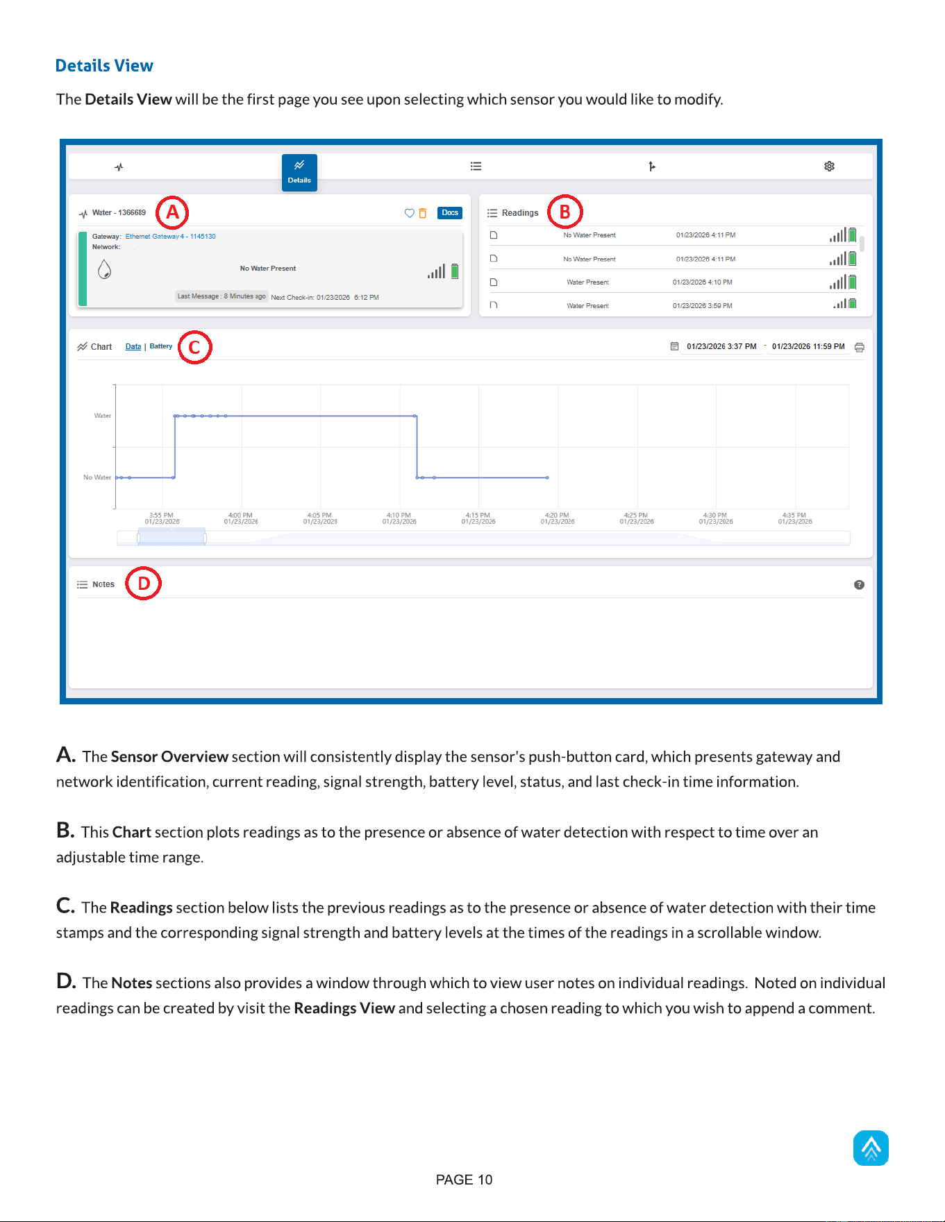
A. The Sensor Overview section will consistently display the sensor's push-button card, which presents gateway and
network identification, current reading, signal strength, battery level, status, and last check-in time information.
B. This Chart section plots readings as to the presence or absence of water detection with respect to time over an
adjustable time range.
C. The Readings section below lists the previous readings as to the presence or absence of water detection with their time
stamps and the corresponding signal strength and battery levels at the times of the readings in a scrollable window.
D. The Notes sections also provides a window through which to view user notes on individual readings. Noted on individual
readings can be created by visit the Readings View and selecting a chosen reading to which you wish to append a comment.
Details View
The Details View will be the first page you see upon selecting which sensor you would like to modify.
PAGE 11
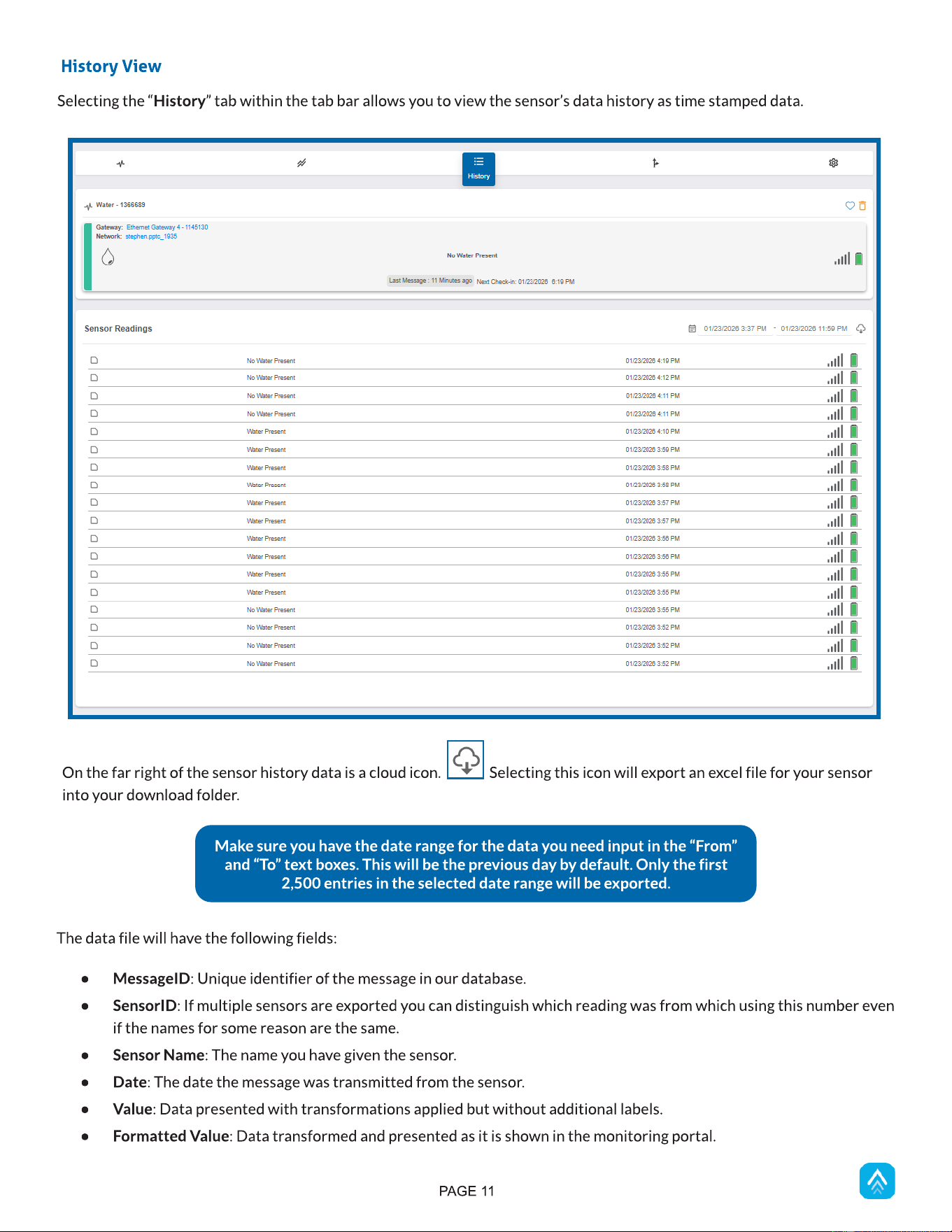
Selecting the ?History? tab within the tab bar allows you to view the sensor?s data history as time stamped data.
History View
On the far right of the sensor history data is a cloud icon. Selecting this icon will export an excel file for your sensor
into your download folder.
The data file will have the following fields:
- MessageID: Unique identifier of the message in our database.
- SensorID: If multiple sensors are exported you can distinguish which reading was from which using this number even
if the names for some reason are the same.
- Sensor Name: The name you have given the sensor.
- Date: The date the message was transmitted from the sensor.
- Value: Data presented with transformations applied but without additional labels.
- Formatted Value: Data transformed and presented as it is shown in the monitoring portal.
Make sure you have the date range for the data you need input in the ?From?
and ?To? text boxes. This will be the previous day by default. Only the first
2,500 entries in the selected date range will be exported.
PAGE 12
- Battery: Estimated life remaining of the battery.
- Raw Data: Raw data as it is stored from the sensor.
- Sensor State: Binary field represented as an integer containing information about the state or the sensor when the
message was transmitted. (See ?Sensor State Explained? below).
- Gateway ID: The Identifier of the gateway that relayed the data from the sensor.
- Alert Sent: Boolean indicating if this reading triggered a notification to be sent from the system.
- Signal Strength: Strength of communication signal between the sensor and the gateway, shown as percentage value.
- Voltage: Actual voltage measured at the sensor battery used to calculate battery percent-age, similar to Received
Signal you can use one or the other or both if they help you.
Note on Sensor State: The value presented here is generated from a single byte of stored data. A byte consists of eight bits of
data that we read as Boolean (True (1)/False (0)) fields.
Using a temperature sensor as an example: If the sensor is using factory calibrations, the Calibrate Active field is set as True
(1) so the bit values are 00010000 and it is represented as 16.
If the sensor is outside the Min or Max threshold, the Aware State is set as True (1) so the bit values are 00000010 and it is
represented as 2.
If the sensor has just been powered on or reset for any reason, the Test bit is set as True (1) so the bit values are 00000001
and it is represented as 1.
If the user has calibrated the sensor, this field, the Calibrate Active field, is set as False AND the sensor is operating inside the
Min and Max Thresholds, the bits look like 00000000 this is represented as 0.
PAGE 13
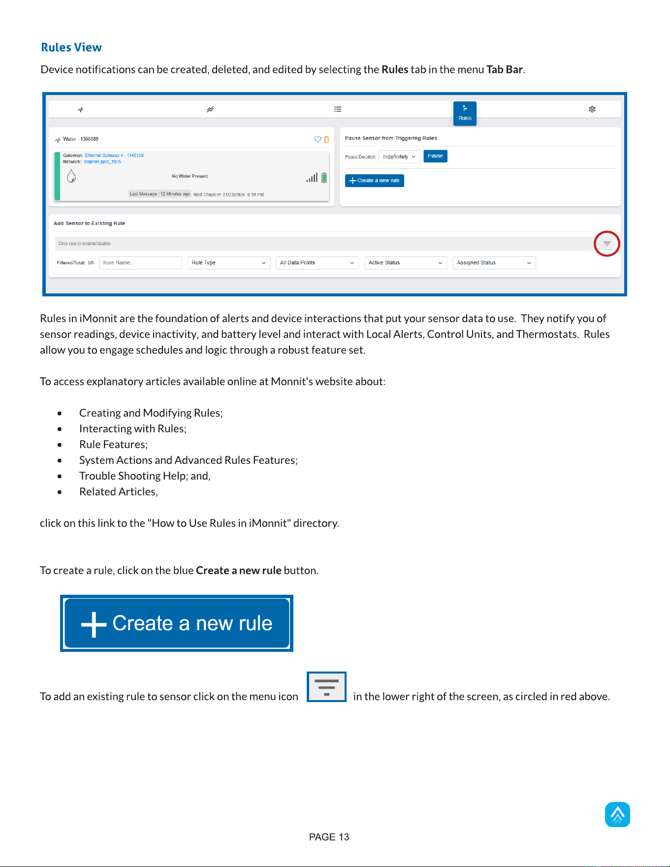
Device notifications can be created, deleted, and edited by selecting the Rules tab in the menu Tab Bar.
Rules View
Rules in iMonnit are the foundation of alerts and device interactions that put your sensor data to use. They notify you of
sensor readings, device inactivity, and battery level and interact with Local Alerts, Control Units, and Thermostats. Rules
allow you to engage schedules and logic through a robust feature set.
To access explanatory articles available online at Monnit's website about:
- Creating and Modifying Rules;
- Interacting with Rules;
- Rule Features;
- System Actions and Advanced Rules Features;
- Trouble Shooting Help; and,
- Related Articles,
click on this link to the "How to Use Rules in iMonnit" directory.
To create a rule, click on the blue Create a new rule button.
To add an existing rule to sensor click on the menu icon in the lower right of the screen, as circled in red above.
PAGE 14
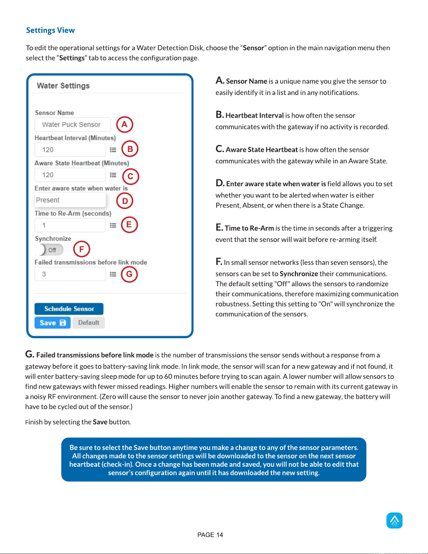
To edit the operational settings for a Water Detection Disk, choose the ?Sensor? option in the main navigation menu then
select the ?Settings? tab to access the configuration page.
Settings View
Be sure to select the Save button anytime you make a change to any of the sensor parameters.
All changes made to the sensor settings will be downloaded to the sensor on the next sensor
heartbeat (check-in). Once a change has been made and saved, you will not be able to edit that
sensor?s configuration again until it has downloaded the new setting.
A. Sensor Name is a unique name you give the sensor to
easily identify it in a list and in any notifications.
B. Heartbeat Interval is how often the sensor
communicates with the gateway if no activity is recorded.
C. Aware State Heartbeat is how often the sensor
communicates with the gateway while in an Aware State.
D. Enter aware state when water is field allows you to set
whether you want to be alerted when water is either
Present, Absent, or when there is a State Change.
E. Time to Re-Arm is the time in seconds after a triggering
event that the sensor will wait before re-arming itself.
F. In small sensor networks (less than seven sensors), the
sensors can be set to Synchronize their communications.
The default setting "Off" allows the sensors to randomize
their communications, therefore maximizing communication
robustness. Setting this setting to "On" will synchronize the
communication of the sensors.
A
B
G. Failed transmissions before link mode is the number of transmissions the sensor sends without a response from a
gateway before it goes to battery-saving link mode. In link mode, the sensor will scan for a new gateway and if not found, it
will enter battery-saving sleep mode for up to 60 minutes before trying to scan again. A lower number will allow sensors to
find new gateways with fewer missed readings. Higher numbers will enable the sensor to remain with its current gateway in
a noisy RF environment. (Zero will cause the sensor to never join another gateway. To find a new gateway, the battery will
have to be cycled out of the sensor.)
Finish by selecting the Save button.
C
D
E
F
G
PAGE 15
VII. SUPPORT
For technical support and troubleshooting tips, please visit our support library at monnit.com/support/. If you are unable to
solve your issue using our online support, email Monnit Support at support@monnit.com with your contact information and a
description of the problem. A support representative will call you within one business day.
For error reporting, please email a full description of the error to support@monnit.com.
WARRANTY
(a) Monnit warrants that Monnit-branded products (Products) will be free from defects in materials and workmanship for a
period of one (1) year from the date the Products arrive at the Customer's shipping address with respect to hardware and
will materially conform to their published specifications for a period of one (1) year with respect to software. Monnit may
resell sensors manufactured by other entities and are subject to their individual Warranties; Monnit will not enhance or
extend those Warranties. Monnit does not warrant that the software or any portion thereof is error-free. Monnit will have no
Warranty obligation with respect to Products subjected to abuse, misuse, negligence, or accident. If any software or
firmware incorporated in any Product fails to conform to the Warranty set forth in this Section, Monnit shall provide a bug fix
or software patch correcting such non-conformance within a reasonable period. Monnit shall provide the fix or patch after
Monnit receives from the Customer (i) notice of such non-conformance, and (ii) sufficient information regarding such
non-conformance so as to permit Monnit to create such bug fix or software patch. If any hardware component of any Product
fails to conform to the Warranty in this Section, Monnit shall, at its option, refund the purchase price less any discounts, or
repair or replace nonconforming Products with conforming Products or Products having substantially identical form, fit, and
function. Monnit will then deliver the repaired or replacement Product to a carrier for land shipment to the Customer within
a reasonable period after Monnit receives from the Customer (i) notice of such non-conformance, and (ii) the
non-conforming Product provided; however, if, in its opinion, Monnit cannot repair or replace on commercially reasonable
terms, it may choose to refund the purchase price. Repair parts and replacement Products may be reconditioned or new. All
replacement Products and parts become the property of Monnit. Repaired or replacement Products shall be subject to the
Warranty, if any remains, originally applicable to the Product repaired or replaced. The Customer must obtain from Monnit a
Return Material Authorization (RMA) number prior to returning any Products to Monnit.
Products returned under this Warranty must be unmodified.
The Customer may return all Products for repair or replacement due to defects in original materials and workmanship, if
Monnit is notified within one year of the Customer?s receipt of the Product. Monnit reserves the right to repair or replace
Products at its own and complete discretion. Products returned under this Warranty must be unmodified and in original
packaging. Monnit reserves the right to refuse Warranty repairs or replacements for any Products that are damaged or not in
original form. For Products outside the one-year Warranty period, repair services are available at Monnit at standard labor
rates for a period of one year from the Customer?s original date of receipt.
(b) As a condition to Monnit?s obligations under the immediately preceding paragraphs, Customer shall return Products to be
examined and replaced to Monnit?s facilities, in shipping cartons which clearly display a valid RMA number provided by
Monnit. The Customer acknowledges that replacement Products may be repaired, refurbished or tested, and found to be
complying. The Customer shall bear the risk of loss for such return shipment and shall bear all shipping costs. Monnit shall
deliver replacements for Products determined by Monnit to be properly returned, shall bear the risk of loss and such costs of
shipment of repaired Products or replacements, and shall credit a Customer?s reasonable costs of shipping such returned
Products against future purchases.
(c) Monnit?s sole obligation under the Warranty described or set forth here shall be to repair or replace non-conforming
products as set forth in the immediately preceding paragraph, or to refund the documented purchase price for
non-conforming Products to the Customer. Monnit?s Warranty obligations shall run solely to a Customer, and Monnit shall
have no obligation to the customers of a Customer or other users of the Products.
PAGE 16
THE WARRANTY SET FORTH HEREIN IS THE ONLY WARRANTY APPLICABLE TO PRODUCTS PURCHASED BY THE
CUSTOMER. ALL OTHER WARRANTIES, EXPRESS OR IMPLIED, INCLUDING BUT NOT LIMITED TO THE IMPLIED
WARRANTIES OF MERCHANTABILITY AND FITNESS FOR A PARTICULAR PURPOSE ARE EXPRESSLY DISCLAIMED.
MONNIT?S LIABILITY WHETHER IN CONTRACT, IN TORT, UNDER ANY WARRANTY, IN NEGLIGENCE, OR
OTHERWISE SHALL NOT EXCEED THE PURCHASE PRICE PAID BY A CUSTOMER FOR THE PRODUCT. UNDER NO
CIRCUMSTANCES SHALL MONNIT BE LIABLE FOR SPECIAL, INDIRECT, OR CONSEQUENTIAL DAMAGES. THE
PRICE STATED FOR THE PRODUCTS IS A CONSIDERATION IN LIMITING MONNIT?S LIABILITY. NO ACTION,
REGARDLESS OF FORM, ARISING OUT OF THIS AGREEMENT MAY BE BROUGHT BY A CUSTOMER MORE THAN
ONE YEAR AFTER THE CAUSE OF ACTION HAS ACCRUED.
IN ADDITION TO THE WARRANTIES DISCLAIMED ABOVE, MONNIT SPECIFICALLY DISCLAIMS ANY AND ALL
LIABILITY AND WARRANTIES, IMPLIED OR EXPRESSED, FOR USES REQUIRING FAIL-SAFE PERFORMANCE IN
WHICH FAILURE OF A PRODUCT COULD LEAD TO DEATH, SERIOUS PERSONAL INJURY, OR SEVERE PHYSICAL OR
ENVIRONMENTAL DAMAGE SUCH AS, BUT NOT LIMITED TO, LIFE SUPPORT OR MEDICAL DEVICES, OR NUCLEAR
APPLICATIONS. PRODUCTS ARE NOT DESIGNED FOR AND SHOULD NOT BE USED IN ANY OF THESE
APPLICATIONS.
Limitation of Warranty and Remedies
CERTIFICATIONS
United States FCC
This device complies with part 15 of the FCC Rules. Operation is subject to the following two conditions: (1) This device
may not cause harmful interference, and (2) this device must accept any interference received, including interference that
may cause undesired operation.
WARNING: Changes or modifications not expressly approved by
Monnit could void the user?s authority to operate the equipment.
Operating Conditions Statement per 47 C.F.R. § 15.19(a)(3)
This equipment has been tested and found to comply with the limits for a Class B digital devices, pursuant to Part 15 of
the FCC Rules. These limits are designed to provide reasonable protection against harmful interference in a residential
installation. This equipment generates, uses, and can radiate radio frequency energy and, if not installed and used in
accordance with the instruction manual, may cause harmful interference to radio communications. However, there is no
guarantee that interference will not occur in a particular installation. If this equipment does cause harmful interference to
radio or television reception, which can be determined by turning the equipment off and on, the user is encouraged to try
to correct the interference by one of more of the following measures:
Class B (Residential) Device Statement per C.F.R. § 15.105
- Reorient or relocate the receiving antenna.
- Increase the separation between the equipment and receiver.
- Connect the equipment into an outlet on a circuit different from that to which the receiver is connected.
- Consult the dealer or an experienced radio/TV technician for help.
PAGE 17
WARNING: To satisfy FCC/ISED exposure requirements for mobile transmitting devices, a separation distance
of 20cm or more should be maintained between the antenna of this device and persons during device
operations. To ensure compliance, operation at closer than this distance is not recommended. The antenna
used for this transmitter must not be co-located in conjunction with any other antenna or transmitter.
Canada ISED
Operating Conditions Statement per Radio Standards Specification RSS-247, Issue 4
This device contains licence-exempt transmitter(s)/receiver(s) that comply with Innovation, Science and
Economic Development Canada's licence-exempt RSS(s). Operation is subject to the following two conditions:
(1) This device may not cause interference.
(2) This device must accept any interference, including interference that may cause undesired operation of
the device.
RF Exposure for FCC/ISED
USER SAFETY REQUIREMENTS
READ CAREFULLY
WARNING: It is the responsibility of the user to enforce the country regulation and the specific environment
regulation.
WARNING: This product is not certified for use in hazardous locations (HAZLOC) where there is a risk of
explosions.
WARNING: IF THE SENSOR IS USED IN A MANNER NOT SPECIFIED BY THE MANUFACTURER, THE
PROTECTION PROVIDED BY THE EQUIPMENT MAY BE IMPAIRED. Do not disassemble the product; any
mark of tampering will compromise the warranty validity. We recommend following the instructions of this user
guide for correct setup and use of the product. Please handle the product with care, avoiding any dropping and
contact with the internal circuit board as electrostatic discharges may damage the product.
WARNING: The device has a mechanical stress rating of IK06, meaning its housing and/or its readings could be
compromised by an impact with greater energy than one Joule.
Justification of a mechanical impact rating less than five Joules exists by: (1) a documented Risk Analysis performed and
maintained by Monnit; (2) installation of the sensor in locations that cannot easily be touched by unauthorized persons or
the general public; (3) the equipment being only accessible in normal use for occasional operations such as adjustment,
programming, or maintenance.
WARNING: DO NOT rely solely on the sensor system to prevent: (1) one or more fatalities; (2) disabling injury or
illness; (3) chemical release with acute or public health impact; (4) chemical release with temporary environmental
or public health impact; (5) system or facility loss; and/or, (6) major subsystem loss.
PAGE 18
WARNING: The use of this product may be dangerous and has to be avoided in the following areas:
- Where it can interfere with other electronic devices in environments such as hospitals airports, aircrafts, etc.
- Wherethere is risk of explosion such as gasoline stations, oil refineries, etc.

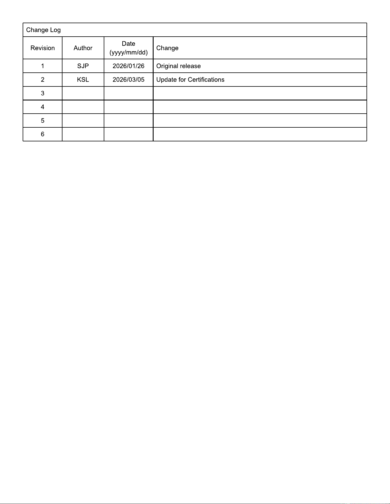
Change Log
Revision Author
Date
(yyyy/mm/dd)
Change
1 SJP 2026/01/26 Original release
2 KSL 2026/03/05 Update for Certifications
3
4
5
6