83249
3
49"
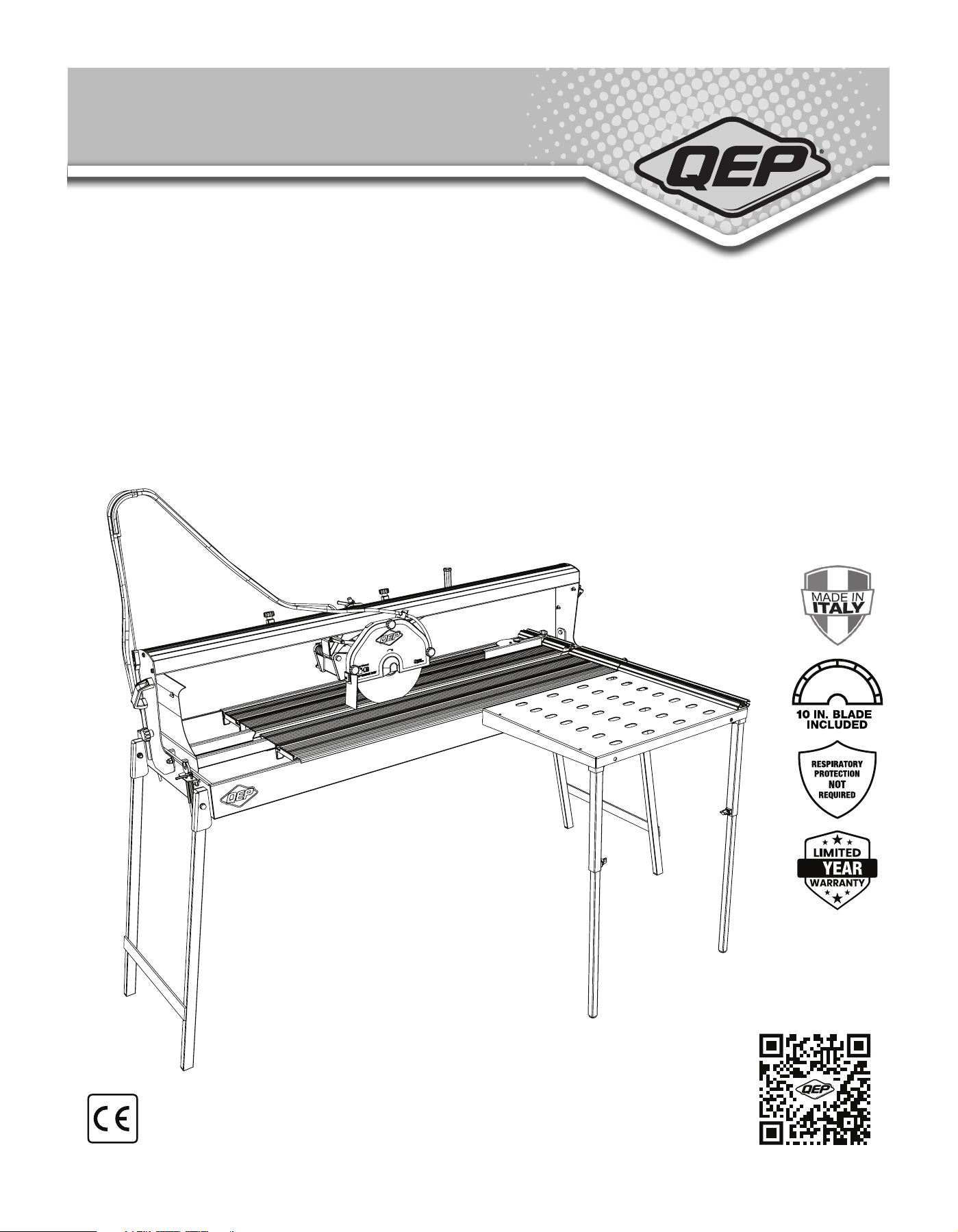
BRIDGE SAW
USER MANUAL
SCIE À PONT 49 PO (125 CM)
MANUEL UTILISATEUR
SIERRA TIPO PUENTA DE 125 CM
MANUAL DEL USUARIO
Make sure outline
aligns perfectly
PARA VER EL MANUAL DE USUARIO Y MÁS DETALLES
SOBRE EL PRODUCTO, ESCANEE EL CÓDIGO QR
FOR OWNER'S MANUAL AND MORE PRODUCT INFO, SCAN THE QR CODE
POUR CONSULTER LE MANUEL UTILISATEUR ET AVOIR PLUS D’INFORMATIONS
CONCERNANT LES PRODUITS, VEUILLEZ SCANNER LE CODE QR

2
TABLE OF CONTENTS
PRODUCT SPECIFICATIONS .................................................................................................................................... 2
SAFETY INFORMATION ........................................................................................................................................... 3-7
RESIDUAL RISK ...................................................................................................................................................... 8
OVERVIEW OF BRIDGE SAW .................................................................................................................................. 9
ASSEMBLY / COMPONENTS .................................................................................................................................... 10-12
OPERATION ............................................................................................................................................................ 13-14
CARE & MAINTENANCE .......................................................................................................................................... 15-16
TROUBLESHOOTING ...................................................................................................................................... 17
SCHEMATICS ................................................................................................................................... 18-20
TECHNICAL DATA LABEL / SYMBOLS & SIGNS ......................................................................................................... 21
ENVIRONMENTAL SPECIFICATIONS OF USE & STORAGE .......................................................................................... 22
TRANSPORTATION .................................................................................................................................................. 22
REPLACEMENTS PARTS LIST ................................................................................................................................. 23
To avoid electrical hazards, re hazards or damage to the tile saw, use proper circuit protection. This tile saw is wired at the factory for 110-120 Volt operation. It must
be connected to a 110-120 Volt / 15 Ampere time delay fuse or circuit breaker. To avoid shock or re, replace power cord immediately if it is worn, cut or damaged in
any way. Before using your tile saw, it is critical that you read and understand these safety rules. Failure to follow these rules could result in serious injury to
you or damage to the tile saw.
MOTOR
Type ........................................ 1.8HP
Amps ....................................... 12
Voltage .................................... 120
Hz ............................................ 60
RPM (no load) .......................... 3400
Overload Protection .................. NO
*Thermal Protected 155°C
TABLE
Assembled Size ........................
33" x 63" x 20.3"
(838 mm x 1600 mm x 516 mm)
Table Extension ........................
Right side of main table
33" x 23.3" x 19.5"
(838 mm x 592 mm x 495 mm)
Weight ......................................... 118 lb. (54 kg)
SAW
Blade Size .............................................. 10 in. (254 mm)
Arbor Size ............................................... 5/8 in. (16 mm)
Blade Type ..............................................
IP ...........................................................
Sound Information .................................
Vibration Information ..............................
Premium Diamond Blade
54
LW = 71.4 / 0.0 db(A) / mW(A)
LOP = 62.7 dB(A)
LOP Max = 100.7 dB(C)
1.15 m/s
2
(0.28 m/s
2
)
CUTTING CAPACITIES
Straight Cut ............................................ 49" (with plunge)
Diagonal Cut ........................................... 34.5"
Max Tile Depth ....................................... 2.75"
Max Tile Depth in single pass ................. 1.57"
Water Tray Capacity................................. 13.2 gal. (50 L)
WARNING
!
Some dust created by power sanding, sawing, grinding, drilling and other construction activities contains chemicals known to the state of California to cause
cancer, birth defects or other reproductive harm. Some examples of these chemicals are:
• Lead from lead-based paints,
• Crystalline silica from bricks and cement and other masonry products
• Arsenic and chromium from chemically-treated lumber.
Your risk from these exposures varies, depending on how often you do this type of work. To reduce your exposure to these chemicals: work in a well ventilated
area, and work with approved safety equipment, such as those dust masks that are specially designed to lter out microscopic particles. Avoid prolonged
contact with dust from power sanding, sawing, grinding, drilling, and other construction activities. Wear protective clothing and wash exposed areas with soap
and water. Allowing dust to get into your mouth, eyes, or lay on the skin may promote absorption of harmful chemicals.
Use of this tool can generate and/or disperse dust, which may cause serious and permanent respiratory or other injury. Always use NIOSH/OSHA approved respiratory
protection appropriate for the dust exposure. Direct particles away from face and body. Handling the power cord on this product may expose you to chemicals known
to the State of California to cause cancer and birth defects or other reproductive harm. Wash hands after handling.
WARNING
!
WARNING
!
PRODUCT SPECIFICATIONS
CALIFORNIA PROPOSITION 65

3
To reduce risk of injury:
• Before any use, be sure everyone using this tool reads and understands all safety instructions and other information
contained in this manual.
• Save these instructions and review frequently prior to use and in instructing others.
• Keep guards in place and in working order.
• Keep work area clean. Cluttered areas and benches invite accidents.
• Don't use in dangerous environment. Don’t use power tools in damp or wet locations, or expose them to rain.
Keep work area well lighted.
• Keep children away. All visitors should be kept safe distance from work area.
• Don't force tool. It will do the job better and safer at the rate for which it was designed.
• Use right tool. Don’t force tool or attachment to do a job for which it was not designed.
• Use proper extension cord. Make sure your extension cord is in good condition. When using an extension cord,
be sure to use one heavy enough to carry the current your product will draw. An undersized cord will cause a drop in
line voltage resulting in loss of power and overheating. Minimum Gauge for Cord Sets shows the correct size to use
depending on cord length and nameplate ampere rating. If in doubt, use the next heavier gauge.
The smaller the gauge number, the heavier the cord.
• Wear proper apparel. Do not wear loose clothing, neckties, rings, bracelets, or other jewelry which may get caught in
moving parts. Nonslip footwear is recommended. Wear protective hair covering to contain long hair.
• Always use safety glasses. Everyday eyeglasses only have impact resistant lenses, they are NOT safety glasses.
• Secure work. Use clamps or a vise to hold work when practical.
It’s safer than using your hand and it frees both hands to operate tool.
• Don't overreach. Keep proper footing and balance at all times.
• Maintain tools with care. Keep tools sharp and clean for best and safest performance. Follow instructions for
lubricating and changing accessories.
• Disconnect tools before servicing; when changing accessories, such as blades.
• Reduce the risk of unintentional starting. Make sure switch is in off position before plugging in.
• Use recommended accessories. Consult the owner’s manual for recommended accessories. The use of improper
accessories may cause risk of injury to persons.
• Never stand on tool. Serious injury could occur if the tool is tipped or if the cutting tool is unintentionally contacted.
• Check damaged parts. Before further use of the tool, a guard or other part that is damaged should be carefully
checked to determine that it will operate properly and perform its intended function – check for alignment of moving
parts, binding of moving parts, breakage of parts, mounting, and any other conditions that may affect its operation.
A guard or other part that is damaged should be properly repaired or replaced.
• Direction of feed. Feed work into blade against the direction of rotation of the blade.
• Never leave tool running unattended. Turn power off. Don’t leave tool until it comes to a complete stop.
IMPORTANT SAFETY INFORMATION
WARNING
!

4
• Wear appropriate hearing protection during use. Under some conditions and duration of use, noise from this product may
contribute to hearing loss.
• Do not connect unit to electrical power source until complete instructions are read and understood.
• Don't operate saw without the 10" diamond blade cover in place.
• Clean tile saw after each use for optimal operation.
• Keep hands out of path of the 10" diamond blade.
Never cut a piece where hand would be 3" (76 mm) or less from the 10" diamond blade.
• Do not perform any operation freehand, that is without holding the workpiece rmly against the fence or edge guide.
• Never reach in back of the 10" diamond blade.
• Don't - Cut dry. If the 10" diamond blade is not cooled with water, serious damage will occur. Dry
• cutting will increase exposure to harmful airborne dust.
• Turn off the tool and wait for the 10" diamond blade to stop before moving the workpiece or changing settings.
• To reduce risk of injury, return the table to it's forward position after each cut.
• Do - Use side table extension to support large tile.
• Do - Make certain the 10" diamond blade rotates in the correct direction as indicated by the arrow
on the 10" diamond blade.
• Do - Be sure all clamp handles and knobs are tight before starting any operation.
• Do - Be sure all 10" diamond blade and clamp washers are clean and recessed sides of collars are against the 10"
diamond blade. Tighten arbor nut securely.
• Do - Keep the 10" diamond blade properly aligned.
• Do - Keep the motor air slots free of chips and dirt.
• Do - Always empty water from the reservoir and disconnect from the power source before transporting. Water can
splash into electrical components.
• Do - Keep hands out of the path of the 10" diamond blade.
• Do - Shut off power, disconnect cord from power source and wait for the 10" diamond blade to stop before servicing,
adjusting tool or changing 10" diamond blade.
• Don't - Attempt to operate on anything but designated voltage. Incorrect voltage may result in shock, re, or
unpredictable operation.
• Don't - Operate unless all knobs and clamps are tight.
• Don't - Use diamond blades larger or smaller than those which are recommended.
• Don't - Force cutting action. Allow motor to reach full speed before cutting.
Stalling or partial stalling of motor can cause major damage.
• Don't - Use metal cutting abrasive wheels.
The excessive heat and abrasive particles generated by them will damage the saw.
• Do - Use continuous rim blades only, no serrated edges or toothed 10" diamond blades.
• Don't - Allow anyone to stand behind saw.
• Don't - Place either hand in the 10" diamond blade area when the saw is connected to the power source.
• Don't - Use 10" diamond blades rated less than 4000 R.P.M.
• Don't - Place hands closer than 3" (76 mm) from the 10" diamond blade.
• Don't - Reach behind or underneath the saw unless it is turned off and unplugged.
• Don't - Move either hand from saw or workpiece until the 10" diamond blade has stopped.
• Secure work. Always place tile at on table and securely against fence.
• Never use a pan heater or other heat source for heating water. Damage to the tool, re or personal injury could result.
• If the plug or receptacle does get wet, Don't unplug the cord. Disconnect the fuse or circuit
• breaker that supplies power to the tool. Then unplug and examine for presence of water in the receptacle.
SAFETY INSTRUCTIONS FOR TILE SAWS
CAUTION
!

5
To avoid electrical hazards, re hazards, or damage to the tool, use proper circuit protection. Use a separate electrical
circuit for your tool. Your tile saw is wired at the factory for 120 V operation. Connect to a 120 V, 15 Amp circuit and use a
15 Amp time delay fuse or circuit breaker. To avoid shock or re, if power cord is worn, cut, or damaged in any way, have
it replaced immediately.
GROUNDING INSTRUCTIONS
This tool must be grounded while in use to protect the operator from electrical shock.
IN THE EVENT OF A MALFUNCTION OR BREAKDOWN, grounding provides a path of least resistance for electric currents
and reduces the risk of electric shock. This tool is equipped with an electrical cord that has an equipment-grounding
conductor and a grounding plug. The plug must be plugged into a matching receptacle that is properly installed and
grounded in accordance withall local codes and ordinances.
DO NOT MODIFY THE PLUG PROVIDED.
If it will not t the receptacle, have the proper receptacle installed by a qualied electrician.
IMPROPER CONNECTION of the equipment grounding conductor can result in risk of electric shock. The conductor with
the green insulation (with or without yellow stripes) is the equipment grounding conductor. If repair or replacement of the
electrical cord or plug is necessary, do not connect the equipment grounding conductor to a live terminal.
CHECK with a qualied electrician or service person if you do not completely understand the grounding instructions, or if
you are not certain the tool is properly grounded.
USE only 3-wire extension cords that have three-pronged grounding plugs with three-pole receptacles that
accept the tool’s plug. Repair or replace damaged or worn cords immediately.
Use a separate electrical circuit for your tool. This circuit must not be less than #14 wire and should be protected with a
15 Amp time delay fuse. Before connecting the motor to the power line, make sure the switch is in the off position and the
electric current is rated the same as the current stamped on the motor nameplate.
Running at a lower voltage will damage the motor.
GUIDELINES FOR EXTENSION CORDS USE THE PROPER EXTENSION CORD.
Make sure your extension cord is in good condition. Use an extension cord heavy enough to carry the current your product
will draw. An undersized cord will cause a drop in line voltage resulting in loss of power, overheating and burning out of the
motor. The table below shows the correct size to use depending on cord length and nameplate ampere rating. If in doubt,
use the next heavier gauge. The smaller the gauge number, the heavier the cord.
Make sure your extension cord is properly wired and in good condition. Always replace a damaged extension cord or have
it repaired by a qualied technician before using it. Protect your extension cords from sharp objects, excessive heat and
damp or wet areas.
ELECTRICAL SAFETY INFORMATION
WARNING
!
WARNING
!
POWER SUPPLY AND MOTOR SPECIFICATIONS
6
Do not expose to rain or use in damp locations.
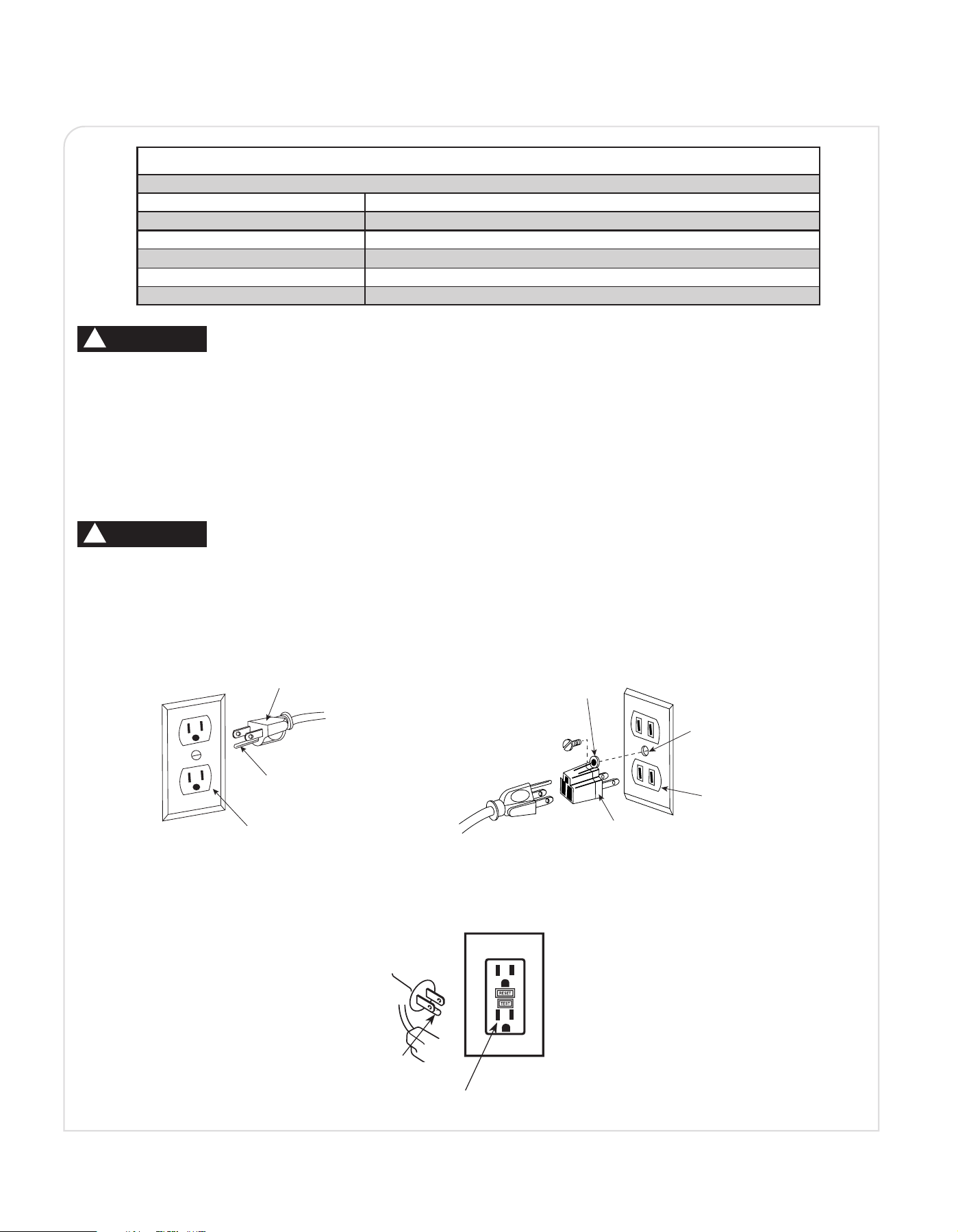
This tool is intended for use on a circuit that has a receptacle like the one illustrated in Fig. A. Fig. A shows a three-pronged
electrical plug and receptacle that has a grounding conductor. If a properly grounded receptacle is not available, an adapter
(Fig. B) can be used to temporarily connect this plug to a two-contact grounded receptacle.
The adapter (Fig. B) has a rigid lug extending from it that MUST be connected to a permanent earth ground, such as a
properly grounded receptacle box.
In all cases, make certain the receptacle is properly grounded.
If you are not sure, have a qualied electrician check the receptacle.
ELECTRICAL SAFETY INFORMATION
(CONTINUED)
WARNING
!
CAUTION
!
MINIMUM GAUGE FOR EXTENSION CORDS (AWG)
(When using 120 Volts only)
Ampere Rating Total Length of Cord
More Than Not More Than 25 ft. 50 ft. 100 ft. 150 ft.
0 6 18 16 16 14
6 10 18 16 14 12
10 12 16 16 14 12
12 16 14 12 Not Recommended
Fig. B
Fig. A
e
Fig. C
Three-Pronged Plug
Grounding Prong
Grounding Prong
Grounding Fault Outlet
Properly Grounded
Three-Pronged Receptacle
Adapter
Grounding Lug
Make sure this
is connected to a
known ground
Two-Pronged
Receptacle
7
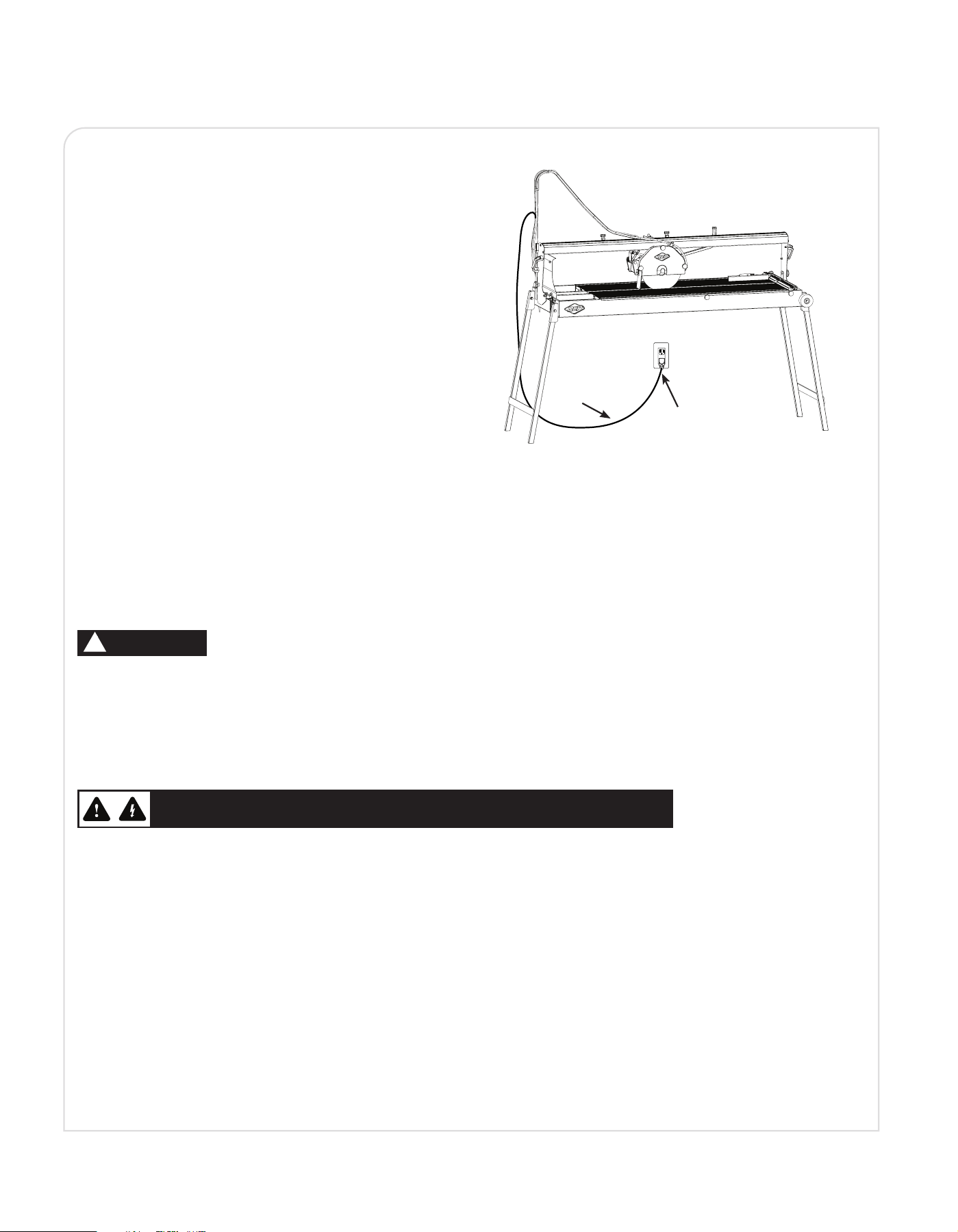
POSITION OF TILE SAW
To avoid the possibility of the appliance plug or receptacle
getting wet, position the tile saw to one side of a wall-
mounted receptacle to prevent water from dripping onto the
receptacle or plug. The user should arrange a “drip loop”
in the cord connecting the saw to a receptacle (see Fig. D).
The “drip loop” is that part of the cord below the level of
the receptacle, or connector if an extension cord is used, to
prevent water traveling along the cord and coming in contact
with the receptacle.
If the plug or receptacle does get wet, DO NOT unplug the
cord. Disconnect the fuse or circuit breaker that supplies
power to the tool. Then, unplug and examine for presence of
water in the receptacle.
EXTENSION CORDS
Do not use damaged extension cords. Examine extension cord before using and replace if damaged.
Do not abuse extension cords and do not yank on any cord to disconnect. Keep cord away from heat and sharp edges.
Always disconnect the extension cord from the receptacle before disconnecting the product from the extension cord.
1. To reduce the risk of electrocution, keep all connections dry and off the ground. Do not touch plug with wet hands.
2. Ground Fault Circuit Interrupter (GFCI) (not included) protection should be provided on the circuit(s) or Fig. C outlet(s) to be
used for the tile saw. Receptacles are available having built-in GFCI protection and may be used for this measure of safety.
CONNECTING TO POWER SUPPLY
RCCB In 16 A Id 30 mA
N.B To ensure correct dunctioning, periodically check the efciency of RCCBs by pressing the push-button on
the front of the device.
• Make sure that the section of the power supply cable cores has been measured according to the starting current and its
length. See minimum gauge table for extension cords on page 6.
Before connecting the machin to the power socket, check that the power supply voltage corresponds to that
shown on the plate of the machine.
• The machine must be connected to an effective earth wire. In case of doubt, do not connect the machine.
WARNING
!
Fig. D
Drip Loop
Power cord
ELECTRICAL SAFETY INFORMATION
(CONTINUED)
THE MACHINE IS TO BE CONNECTED TO THE POWER SUPPLY BY A RESIDUAL
CURRENT CIRCUIT BREAKER (RCCB) WITH THE FOLLOWING CHARACTERISTICS
8
During the design phase, BATTIPAV SRL paid particular attention to the aspects that may generate risks for the safety and health of
operator. In spite of this, there are still some potential risks, which are described below:
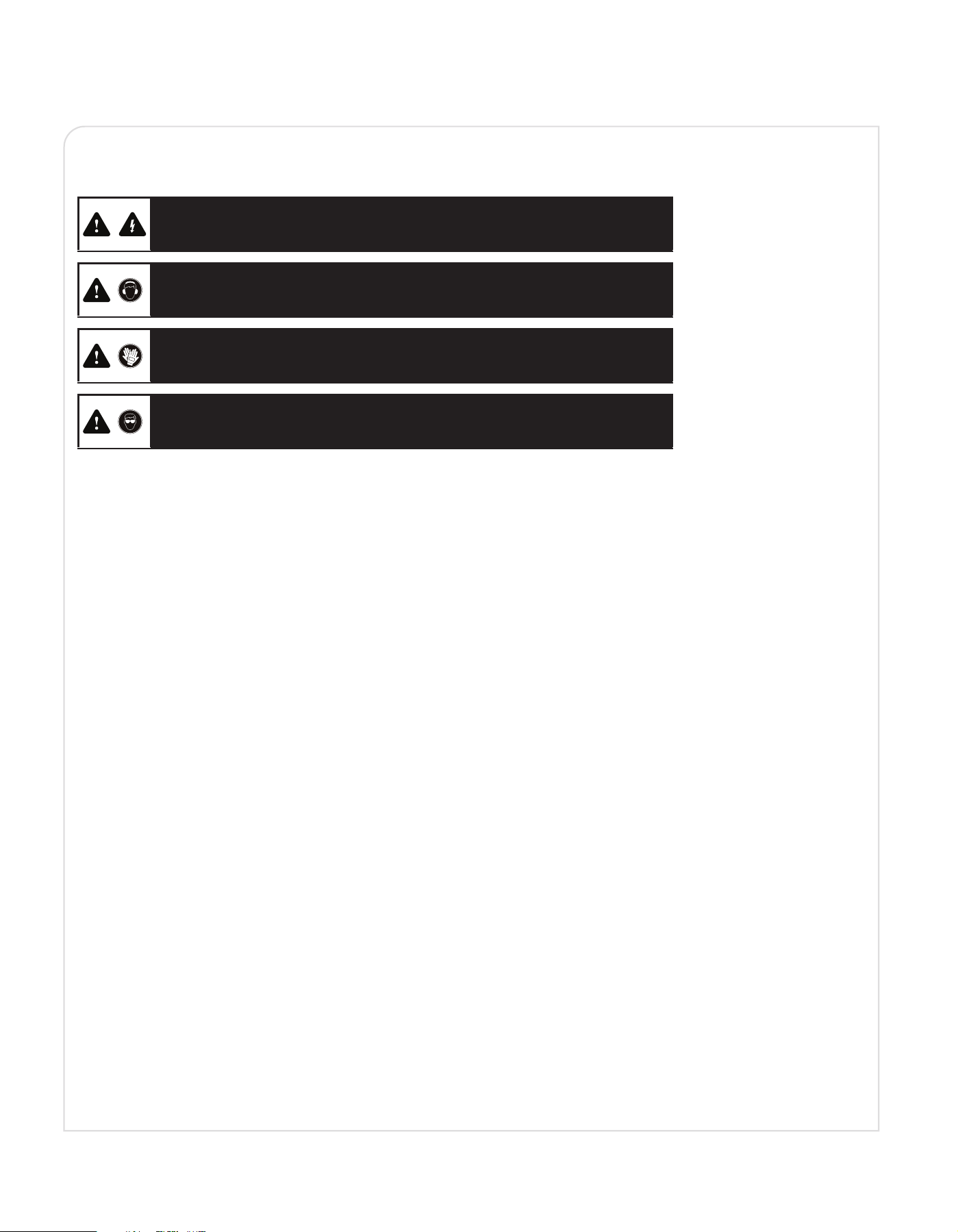
ALWAYS STAY IN THE WORKING POSITION DURING THE MACHINE OPERATION PHASES:
• During material loading.
• During material cutting.
• During the cutting tool deceleration following the machine stop.
RESIDUAL RISK
Danger of presence of electrical current:
The machine has an internal electric system. CONNECT THE MACHINE TO A SYSTEM
WITH DIFFERENTIAL PROTECTION ANDF EFFECTIVE EARTH WIRE.
Danger of prolonged exposure to noise:
The continuous use of the machine causes an exposure to noise levels above 85 dB (A).
OPERATORS MUST USE PROPER EAR DEFENDERS.
Danger of accidental contact with the moving tool:
OPERATORS MUST WEAR HEAVY PROTECTIVE GLOVES.
Danger of exposure to fragments of materials:
OPERATORS MUST WEAR PROTECTIVE GOGGLES.
9
OVERVIEW OF BRIDGE SAW
B
A
C
D
F
E
G
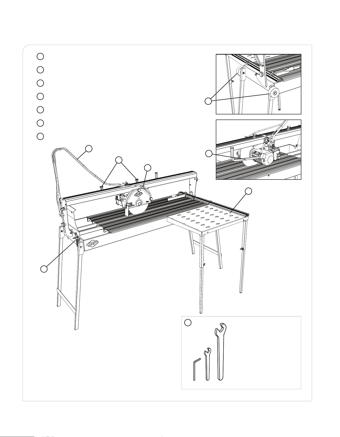
Water Hose
Motor carriage thumbscrews
Extension Table
Water ow valve
Tool storage shelf (Tool Kit Included)
Wheels
Plunge
E
C
F
C
G
Tool Kit Included
5mm Hex wrench & 19 mm
wrench for blade assembly.
10mm wrench for attaching
the nuts on the fence and the
fence to extension table.
8mm wrench used for safety
nut on the blade cover.
03-SP05070
04-SP850015/1
02-SP05011
02-SP05011
05-SP70010/3i
EINRICHTBLATT / INSTRUCTIONS DE MONTAGE
" verlaengerungsstuecke "/ " rallonge plan de travail "
/ ASSEMBLY DIAGRAM INSTRUCTIONSISTRUZIONI DI MONTAGGIO
/ " extension side working bench "" prolunga piano di lavoro "
Method of assembly "FAST"
A
B
USA70241/1i _v1
02-SP05011
02-SP05011
SP05070
(x2)
02-SP05011
(SCREWS, NUTS AND SPANNERS)
VITI, DADI E CHIAVI
SP05011
Installation verfahren "SCHNELLE"
Méthode d'installation "RAPIDE"
Metodo di montaggio " RAPIDO"
Metodo di montaggio " PRECISO"
Method of assembly "PRECISE"
Installation verfahren "PRECISE"
Méthode d'installation "PRECISE"
01-70241/1
2
2
1
A
3
4
A
C
A
D
B
E
C
4499""BBrriiddggee SSaaww SSPP__vv11
(x1) (x1) (x1) (x1) (x1)
SP81807/2USA
(x1)
(x1)
(x1)
SP856033
(x1)(x1)
SP850077
SP857030
(x1)
(x1)
(x4)
SP850052
(x1)(x1)
SP84025
(x1)
SP857008
(x2)
(x2)
(x4)
(x2)
(SCREWS AND NUTS FOR FRAME)
(VITI e DADI PER TELAIO)
SP85060
(x2)
SP65015
(x4)
SP857004/250
(x1)
(x1)
SP902512 8 -
07-SP857004/250
06-SP03055
38-SP850065
01-SP85060
-39 P1/A4
05-SP857008
01-SP85060
01-SP85060
01-SP85060
01-SP85060
41-SPQ857002
13-SP857005/1250
01-SP85060
01-SP85060
01-SP85060
01-SP85060
01-SP85060
37-SP84025
01-SP85060
01-SP85060
40-SP855028
C
33-SP850073
01-SP85060
SP857030
04
-
02-SP850052
07-SP857004/250
04-SP857030
06-SP03055
01-SP85060
13-SP857005/1250
15-SP857071
27-SP65001/1250i
15-SP857071
26-SP90218/1250i
32-SP65025/250C
B
30-SP65012
29-SP65015
31-SP65018
29-SP65015
A
01-SP85060
C
03-SP850077
SP90083/1/1A
(x1)
(x1)
22-SP65042
(x1)
(x1)
16-SP856033
24-SP850054
20-SP65037
38-SP850065
15-SP857071
19-SP81807/2USA
21-SP65033C
36-SP90080/A
35-SP65034
34-SP90083/1/1A
03-SP850077
B
19-SP81807/2USA
17-SP850020
18-SP850021
17-SP850020
14-SP850024
25-SP07071T
A
(x2) (x2)(x1)
SP65018
(x1)
(x1)
10-SP66013/B
(x1)
-09 SP88071/B
SP03055
(x2)
15-SP857071
15-SP857071
15-SP857071
(x1)
23-SP66013/857/B/USA
SP850020
(x1)(x1)
(x2)
(VITI e DADI PER TESTA MOTORE)
(SCREWS AND NUTS FOR POWER PLANT)
SP857071
15-SP857071
15-SP857071
15-SP857071
15-SP857071
15-SP857071
15-SP857071
15-SP857071
15-SP857071
15-SP857071
15-SP857071
15-SP857071
15-SP857071
01-SP85060
42-SP857041
42-SP857041
(x1)
SP857041
(x1)
SP857043i
(x1) (x1)(x1)(x1)
43-SP857039
12-SP70071
11-SPQ70002i
08-SP857043i
44-SPQ70010i
D
E
D
E
115V 60Hz~
USA/B
49” BRIDGE SAW
10
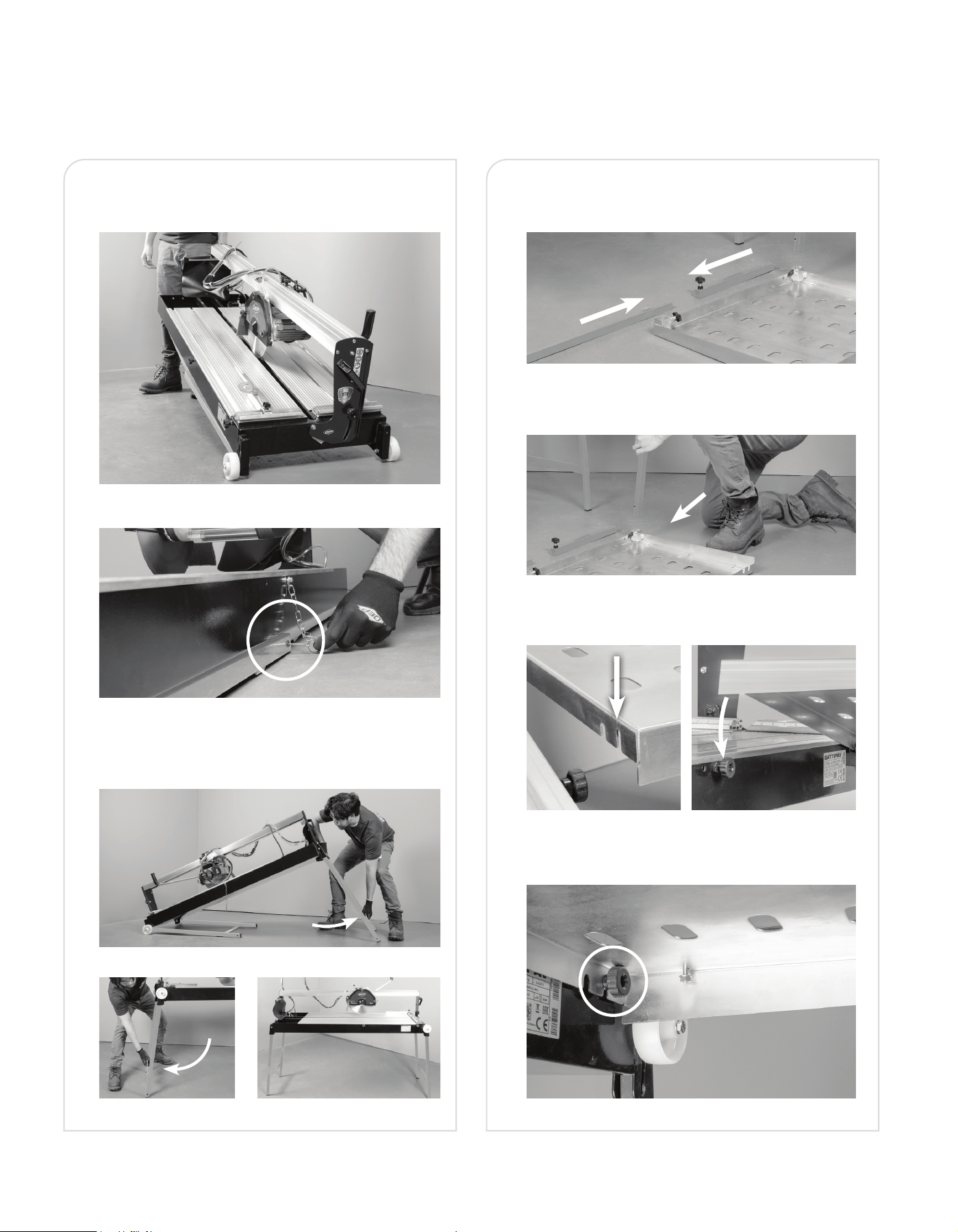
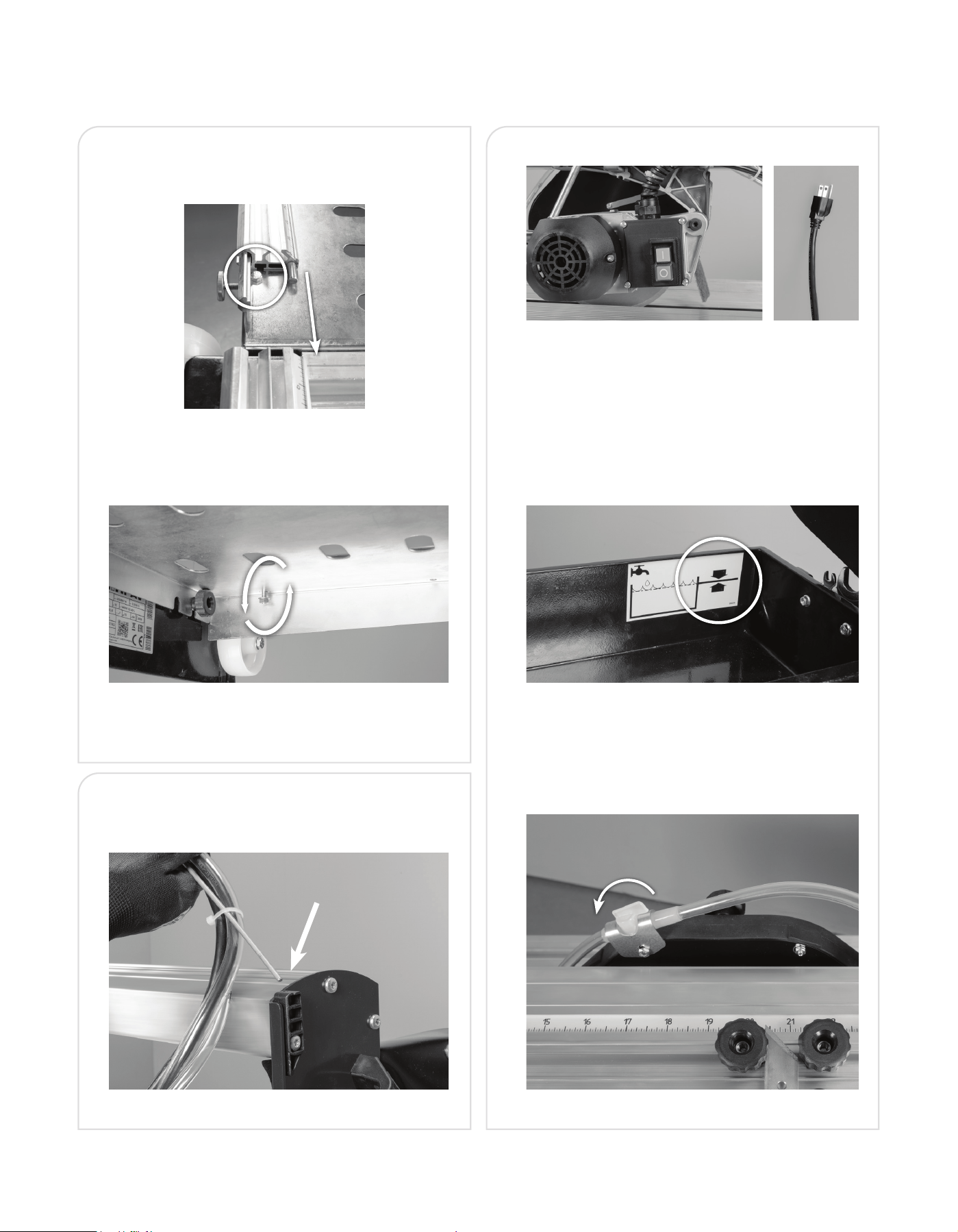
ASSEMBLE EXTENSION TABLE
•
The legs will need to be assembled by inserting the 2
parts together using the thumbscrews.
•
Once assembled, insert leg into the bottom of the
extension table and lock in with thumbscrew.
•
Attach the extension table by locating the outer slot
closest to the edge.
•
Locate the thumbscrew and slide this slot
over the thumbscrew.
UNBOXING AND MOVING THE SAW
•
Remove from box on a stable surface. Use the side
carrying handles to slide the saw out of box.
•
Remove the pin to release the legs.
• Lift the rear leg assembly and slide up into the relevant
slot. Repeat this step for the front leg assembly. Make
sure legs are locked in place and secure.
SYSTEM COMPONENTS
ASSEMBLY
Figure 1.
Figure 2.
Figure 5. Figure 10.
Figure 6.
Figure 7.
Figure 8. Figure 9.
Figure 3.
Figure 4.
11
ON / OFF BUTTONS
•
ON Button – Green
•
OFF Button – Red
•
Power Supply- DISCONNECT during maintenance phases
IMPORTANT
•
Before cutting make sure plug is inserted into drain, then
ll water tray to the level marked between arrows.
•
Water ow valve is located on Blade Guard. Water ow
valve ON position is Parallel with hose.
To slow the water ow turn the valve slowly so it is
Perpendicular to the hose.
INSTALL WATER HOSE HOLDER
•
Insert the metal rod attached to the water pump hose into
the opening on top of the rail.
•
Attach the fence to the extension table by aligning
the fence with nut on top of the table. Slide the fence
groove over the nut.
•
Connect the fence to the bridge saw main table and
lock in place. The nut can be loosened and tighten from
underneath the table.
TIP: loosen nut before sliding the fence.
Tighten nut after fence is aligned.
ASSEMBLY
(CONTINUED)
Figure 13.
Figure 14.
Figure 16.
Figure 15.
Figure 16.
Figure 11.
Figure 12.
Figure 17.
12
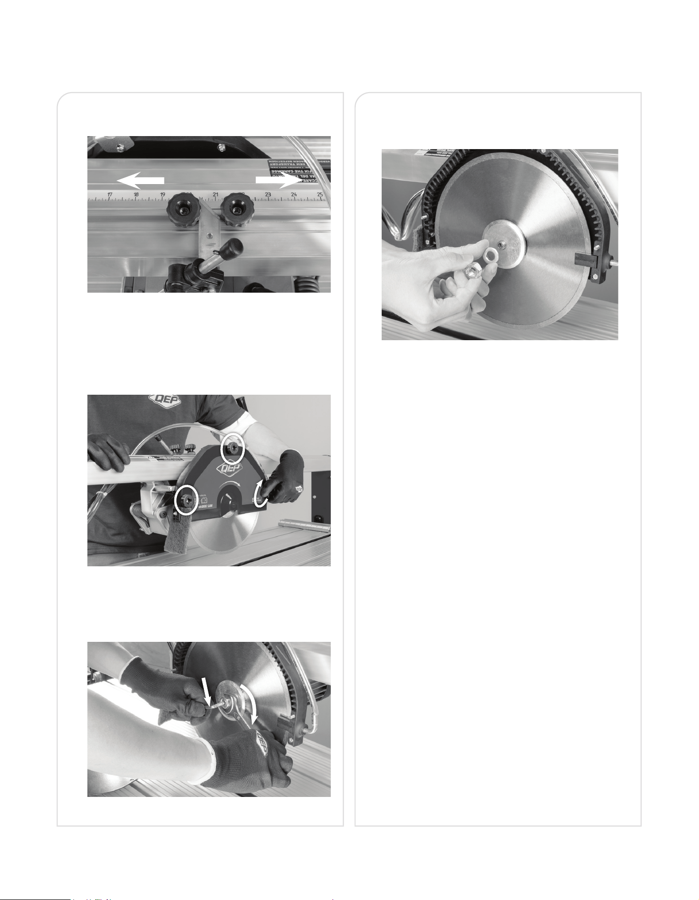
• Turn the 2 thumbscrews to allow the motor carriage to
slide to desired placement. Then tighten thumbscrews.
BLADE ASSEMBLY / DISASSEMBLY
• Disconnect the machine from the power source before
changing or adjusting the blade assembly.
• Unscrew the three knobs from the blade cover and
remove cover.
• Remove the blade fastening nut using the 19mm
wrench and the 5mm hex wrench included by turning
the nut clockwise while holding the 5mm hex bolt still.
• Repeat process in reverse to install the blade making
sure the arrow on the blade is in the correct direction
for cutting.
Figure 21.
ASSEMBLY
(CONTINUED)
Figure 19.
Figure 20.
Figure 18.
13
OPERATION
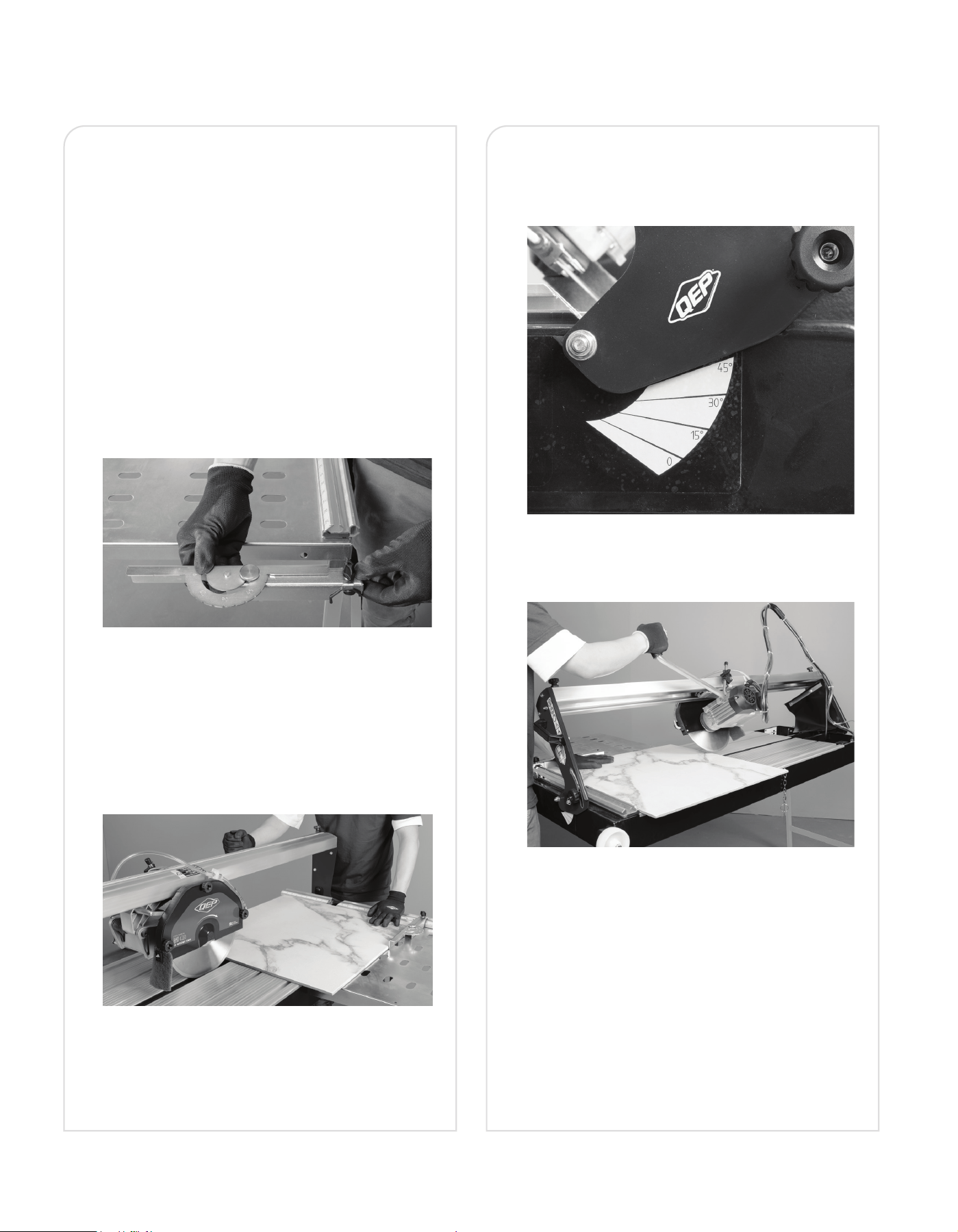
BEVEL CUT See Figures 24-25.
• Before positioning the motor head, make sure that
the tile saw is off and cutting head is not moving.
• Refer to the graded scale located on the upright.
• Move the motor head to the desired angled position
and tighten the thumbscrews.
• Lower the cutting head to the desired position.
• Ensure the tile does not touch the blade before
turning on the tile saw.
• Press the On green button.
• Allow the blade to reach its maximum speed and
wait for the water to ow through hose over the
blade before moving the tile toward the blade.
• When the cut is complete, press the OFF Red button
to turn off tile saw and wait for the blade to stop
completely before removing the tile.
BEFORE STARTING THE MACHINE
• Make sure the tile saw is on level ground using a level.
• Fill the water tray with water to the line.
• Loosen the top knobs holding the head unit (blade) in
place and adjust to where the cuts are required.
• Before rst use, verify blade alignment using a triangle
square to ensure the blade is vertically square. Then, use
an L-square to conrm the fence is square to the blade.
Adjust as needed.
• Place tile on the saw and adjust fence guide as needed.
• Turn on the saw, ensuring the blade is not in contact
with the tile. Conrm that water is owing properly and
reaching the blade as intended.
STRAIGHT CUT See Figures 22-23.
• Adjust the angle guide to zero degrees.
• Place the tile on the table and hold it rmly against
both the angle guide and fence.
• Ensure the tile does not touch the blade before
turning on the tile saw.
• Press the ON green button.
• Allow the blade to reach its maximum speed and
wait for the water to ow through hose over the
blade before moving the tile toward the blade.
• When the cut is complete, press the OFF Red button
to turn off tile saw and wait for the blade to stop
completely before removing the tile.
Figure 24.
Figure 22.
Figure 23.
Figure 25.
14
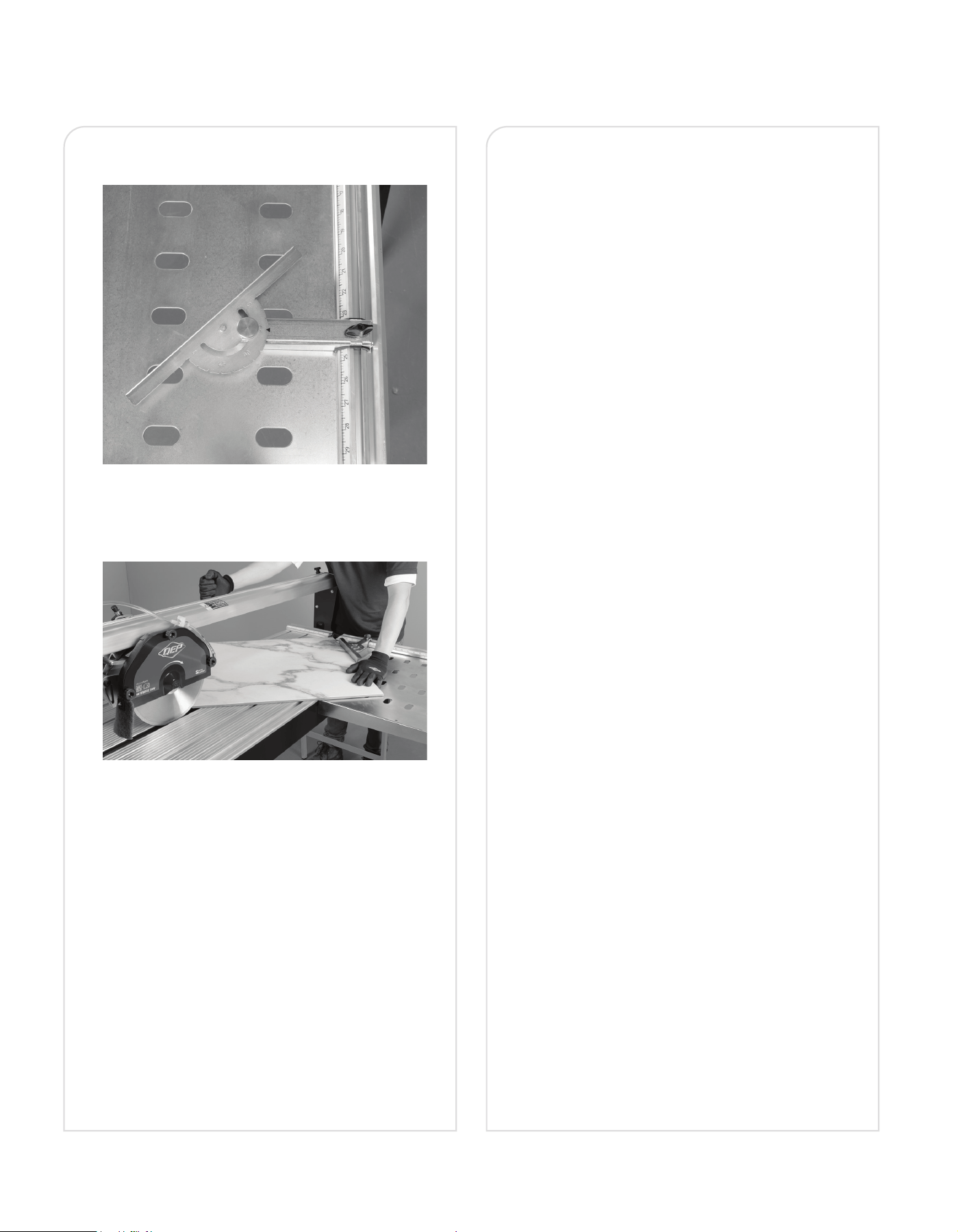
DIAGONAL CUT See Figures 26-27
• Adjust the angle guide to 45 or 90 degrees.
• Place the tile on the table and hold it rmly against
both the angle guide and fence.
• Ensure the tile does not touch the blade before
turning on the tile saw.
• Press the On green button.
• Allow the blade to reach its maximum speed and wait
for the water to ow through hose over the blade
before moving the tile toward the blade.
• When the cut is complete, press the OFF Red button
to turn off tile saw and wait for the blade to stop
completely before removing the tile.
PLUNGE FUNCTION
• The cutting head has a plunge function, which allows
the height adjustment of the cutting blade.
• Make sure the cutting head is in the up position, align
the blade over the portion to cut and pull the handle
down cutting the tile.
OPERATION
(CONTINUED)
Figure 27.
Figure 26.
15
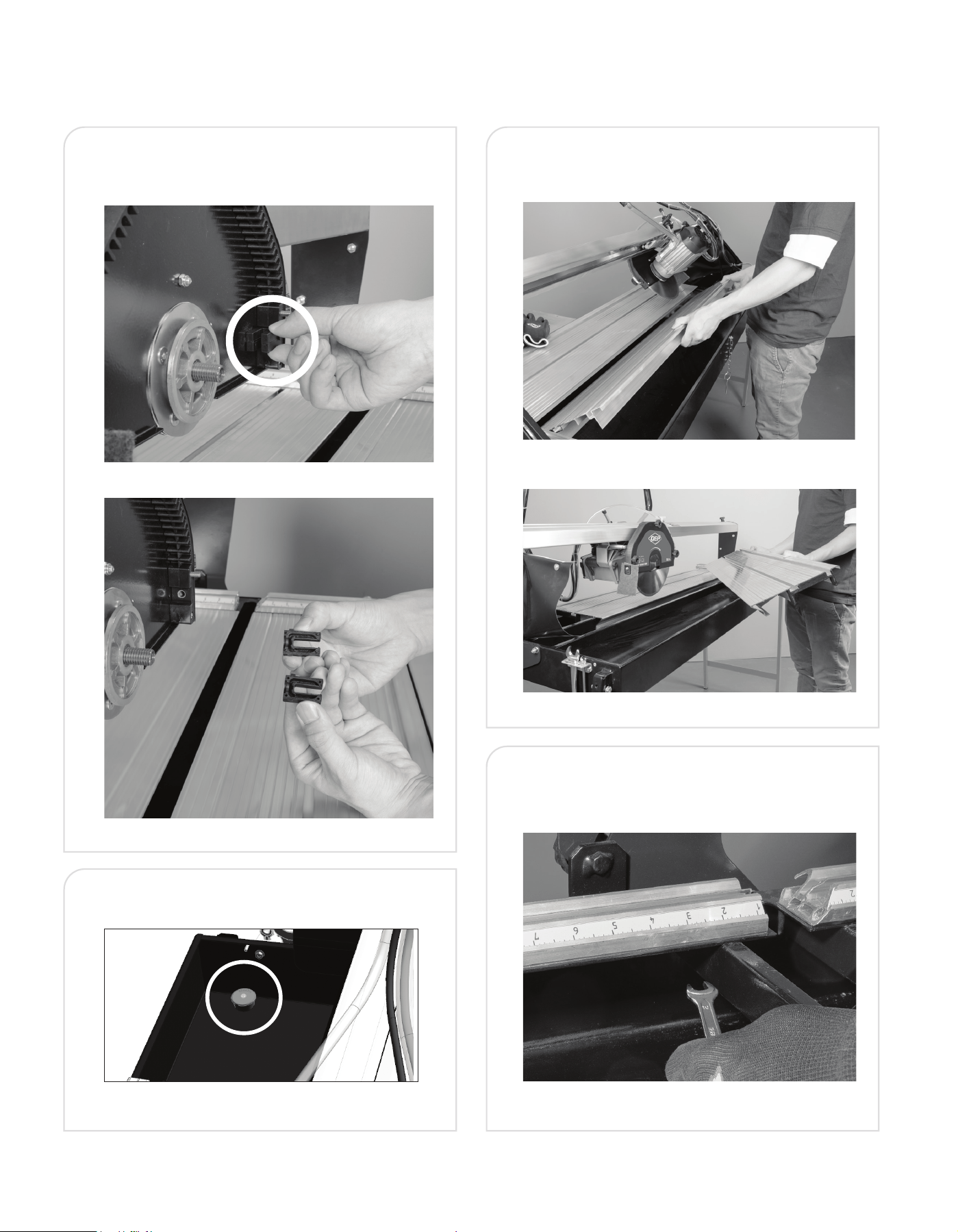
• Lift out trays to wipe down the recovery tray to
remove residual material from the machine.
CARE AND MAINTENANCE
CLEANING SPRAYER
• Remove Blade from blade guard and rinse off the two
water ow guards.
CLEANING THE WATER TRAY
• Remove the plug to drain the water.
Figure 28.
Figure 29.
FENCE ALIGNMENT
• Remove the panels and use the (4) 10mm bolts on the
bottom of fence to re-align the fence.
Figure 33.
Figure 32.
Figure 30.
Figure 31.
16
CARE AND MAINTENANCE
(CONTINUED)
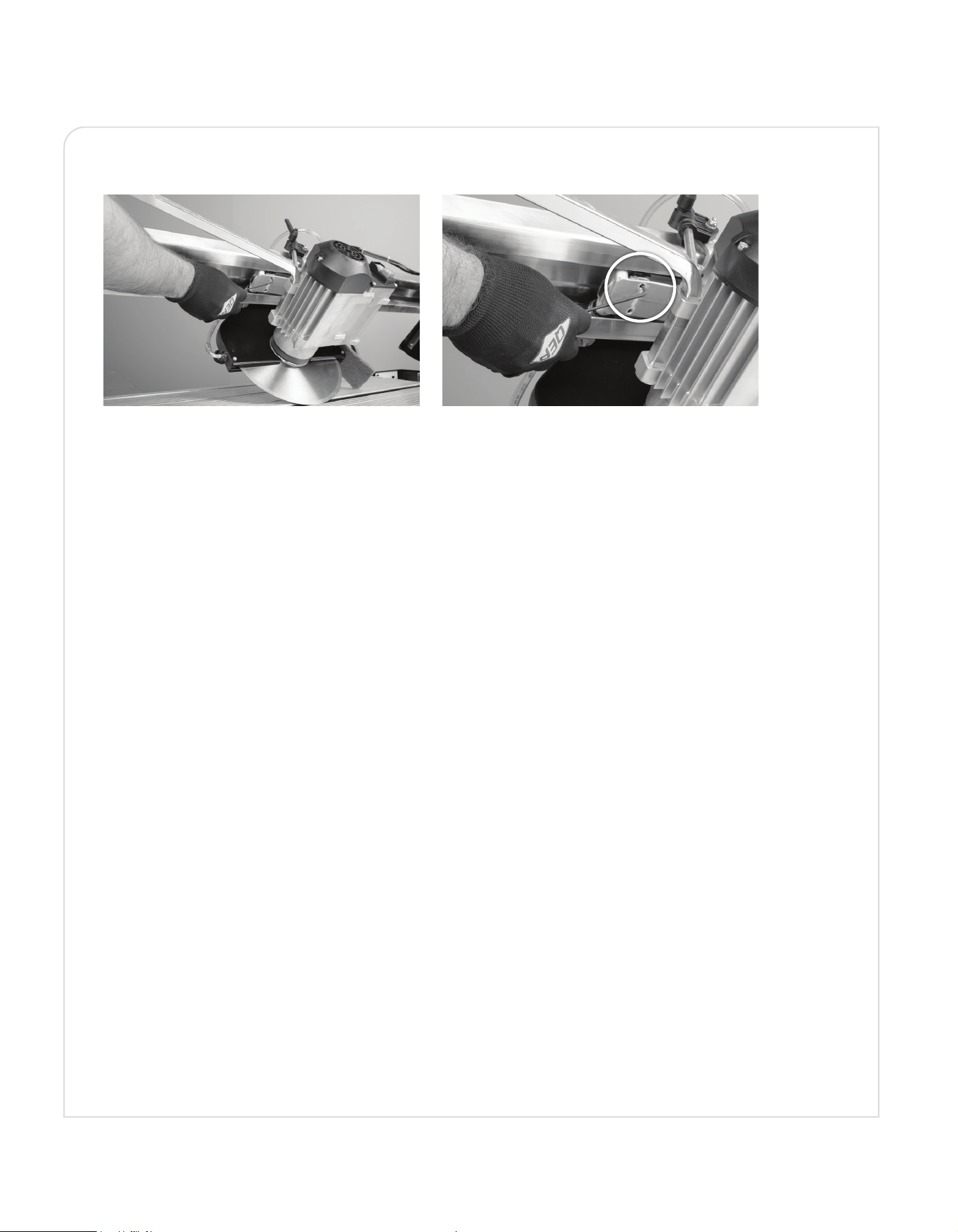
MOTOR CARRIAGE ADJUSTMENT
Vertical motor carriage adjustment can be done using the 3 mm wrench to loosen the screw.
• Screw down the dowel with a 3mm hex wrench until the play is eliminated.
• Lock the register xing nut with a 10 mm wrench.
Figure 34. Figure 35.

17
Do not service, clean or maintain the saw without rst turning off the motor and unplugging the saw from the power source.
Failure to do so may result in serious personal injury.
PROBLEM PROBLEM CAUSE SUGGESTED CORRECTIVE ACTION
Motor does not start. 1. Power cord is not plugged intothe socket.
2. Switch failure.
3. Fuse blown or circuit breaker tripped on
home panel.
1. Plug in properly.
2. Replace switch.
3. Verify there is electrical power at the outlet.
Saw is overheating. 1. The saw continues to operate too long
under pressure.
2. Blockage or dirt jams the ventilation slots
of the motor.
1. Turn the saw off and let it rest until the motor is
cool to touch.
2. Check and clean the ventilation slots of the motor,
removing blockage or dirt.
The pump is not owing water. 1. Water amount is not enough.
2. Water hose is jammed by dirt.
1. Add water until the pump is submerged completely.
2. Clean the water tube, lter and pump lter.
Sliding table is not
sliding smoothly.
1. Too much dirt or tile dust is jammed in
the guide rails or sliding table rollers.
1. Clean the dirt.
Saw vibrates or shakes. 1. Saw wheel not round / damaged / loose.
2. Wheel not tightened on saw, arbot nut
loose.
1. Replace Wheel
2. Tighten arbor nut.
WARNING
!
TROUBLESHOOTING
18
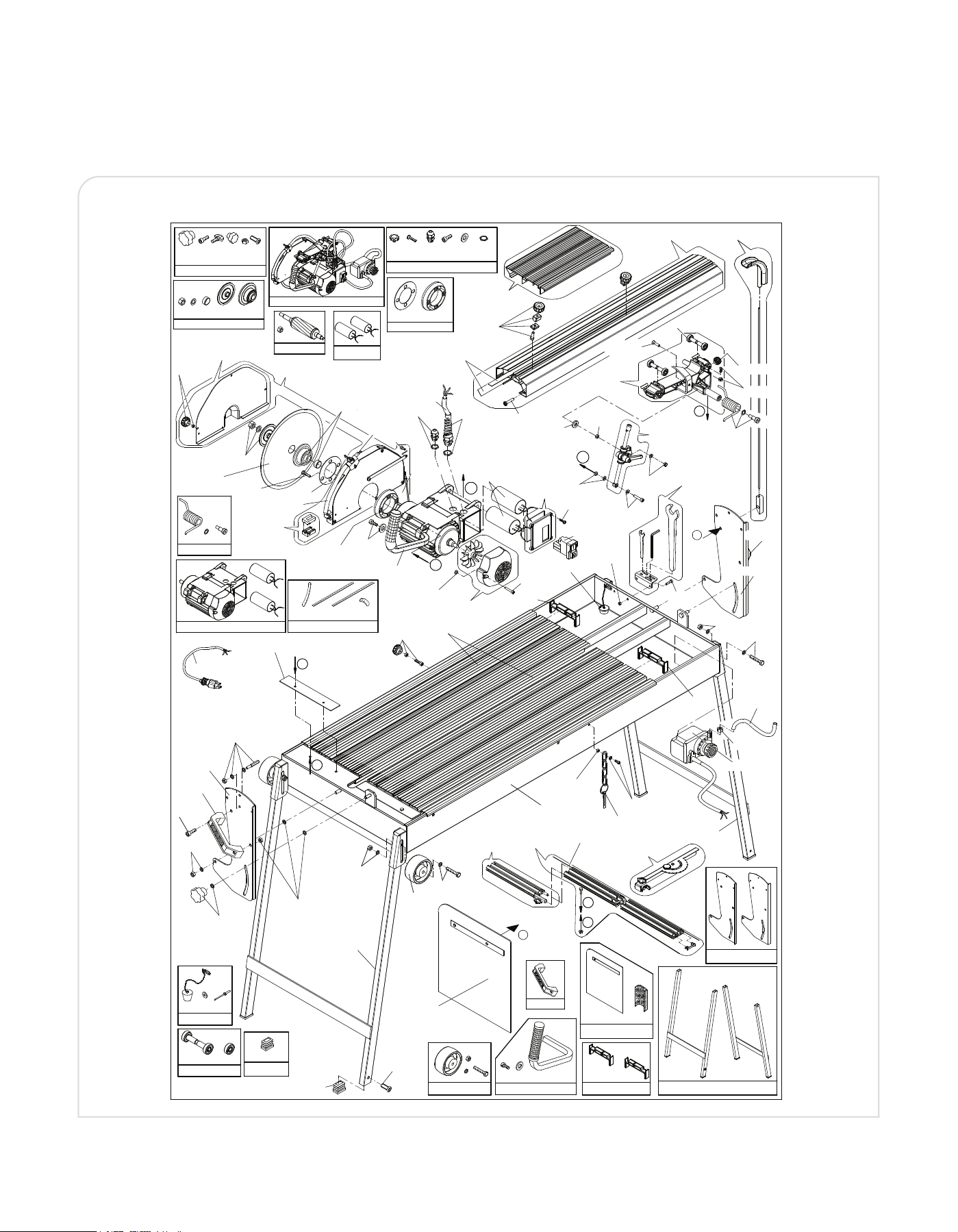
SCHEMATIC - BRIDGE SAW
Q
Q
8
8
5
5
7
7
/
/
B
B
_
_
S
S
P
P
_
_
v
v
2
2
(x1) (x1) (x1) (x1) (x1)
SP81807/2USA
(x1)
(x1)
(x1)
SP856033
(x1)(x1)
SP850077
(x4)
SP850052
(x1)(x1)
SP84025
(x1)
SP857008
(x2)
(x2)
(x4)
(x2)
(SCREWS AND NUTS FOR FRAME)
(VITI e DADI PER TELAIO)
SP85060
(x2)
SP65015
(x4)
SPQ857004/250
(x1)
(x1)
SP902512 8 -
07-SPQ857004/250
06-SP03055
38-SP850065
01-SP85060
-39 P1/A4
05-SP857008
01-SP85060
01-SP85060
01-SP85060
01-SP85060
41-SPQ857002
13-SP857005/1250
01-SP85060
01-SP85060
01-SP85060
01-SP85060
01-SP85060
37-SP84025
01-SP85060
01-SP85060
40-SP855028
C
33-SP850073
01-SP85060
SPQ857030
04
-
02-SP850052
07-SPQ857004/250
04-SPQ857030
06-SP03055
01-SP85060
13-SP857005/1250
15-SP857071
27-SP65001/1250i
15-SP857071
26-SP90218/1250i
32-SP65025/250C
B
30-SP65012
29-SP65015
31-SP65018
29-SP65015
A
01-SP85060
C
03-SP850077
SP90083/1/1A
(x1)
(x1)
22-SP65042
(x1)
(x1)
16-SP856033
24-SP850054
20-SPQ65037TT
38-SP850065
15-SP857071
19-SP81807/2USA
21-SPQ65033C
36-SP90080/A
35-SP65034
34-SP90083/1/1A
03-SP850077
B
19-SP81807/2USA
17-SP850020
18-SP850021
17-SP850020
14-SP850024
25-SP07071T
A
(x2) (x2)(x1)
SP65018
(x1)
(x1)
10-SP66013/B
(x1)
-09 SP88071/B
SP03055
(x2)
15-SP857071
15-SP857071
15-SP857071
(x1)
23-SPQ66013/857/B/USA
SP850020
(x1)(x1)
(x2)
(VITI e DADI PER TESTA MOTORE)
(SCREWS AND NUTS FOR POWER PLANT)
SP857071
15-SP857071
15-SP857071
15-SP857071
15-SP857071
15-SP857071
15-SP857071
15-SP857071
15-SP857071
15-SP857071
15-SP857071
15-SP857071
15-SP857071
01-SP85060
42-SP857041
42-SP857041
(x1)
SP857041
(x1)
SP857043i
(x1) (x1)(x1)(x1)
43-SP857039
12-SP70071
11-SPQ70002i
08-SP857043i
44-SPQ70010/2i
D
E
D
E
SPQ857030
(x1)
(x1)
44-890GP
19
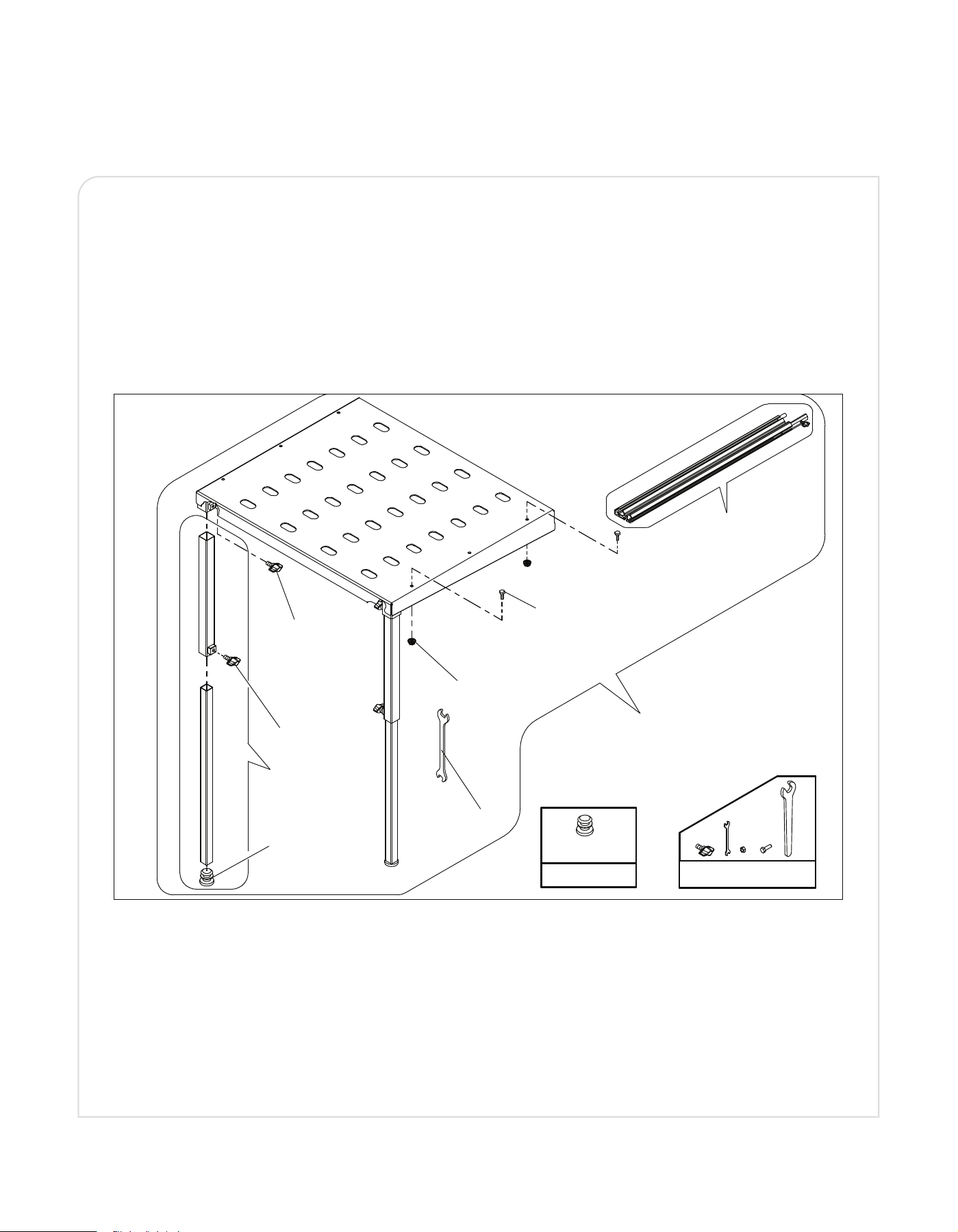
SCHEMATIC - EXTENSION TABLE
03-SP05070
04-SPQ850015/1
02-SP05011
02-SP05011
05-SP70010/3i
EINRICHTBLATT / INSTRUCTIONS DE MONTAGE
" verlaengerungsstuecke "/ " rallonge plan de travail "
/ ASSEMBLY DIAGRAM INSTRUCTIONSISTRUZIONI DI MONTAGGIO
/ " extension side working bench "" prolunga piano di lavoro "
Method of assembly "FAST"
A
B
USA70241/1i_v2
02-SP05011
02-SP05011
SP05070
(x2)
02-SP05011
(SCREWS, NUTS AND SPANNERS)
VITI, DADI E CHIAVI
SP05011
Installation verfahren "SCHNELLE"
Méthode d'installation "RAPIDE"
Metodo di montaggio " RAPIDO"
Metodo di montaggio " PRECISO"
Method of assembly "PRECISE"
Installation verfahren "PRECISE"
Méthode d'installation "PRECISE"
01-USA70241/1
2
2
1
A
3
4
A
03-SP05070
04-SP850015/1
02-SP05011
02-SP05011
05-SP70010/3i
EINRICHTBLATT / INSTRUCTIONS DE MONTAGE
" verlaengerungsstuecke "/ " rallonge plan de travail "
/ ASSEMBLY DIAGRAM INSTRUCTIONSISTRUZIONI DI MONTAGGIO
/ " extension side working bench "" prolunga piano di lavoro "
Method of assembly "FAST"
A
B
USA70241/1i _v1
02-SP05011
02-SP05011
SP05070
(x2)
02-SP05011
(SCREWS, NUTS AND SPANNERS)
VITI, DADI E CHIAVI
SP05011
Installation verfahren "SCHNELLE"
Méthode d'installation "RAPIDE"
Metodo di montaggio " RAPIDO"
Metodo di montaggio " PRECISO"
Method of assembly "PRECISE"
Installation verfahren "PRECISE"
Méthode d'installation "PRECISE"
01-70241/1
2
2
1
A
3
4
A
20
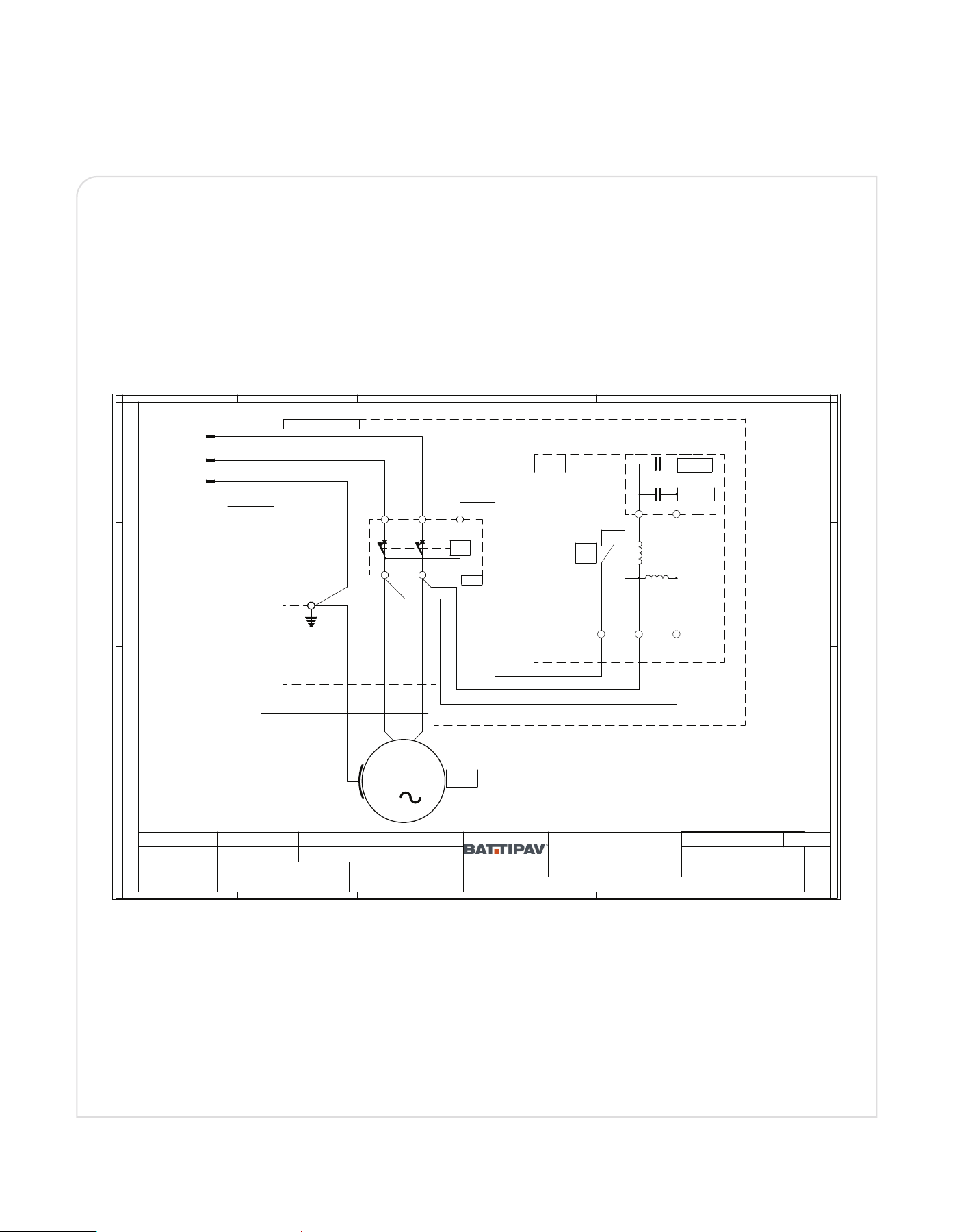
SCHEMATIC - ELECTRICAL TABLE
1
1
2
2
3
3
4
4
5
5
6
6
A A
B B
C C
D D
*
*
Modifiche:
DENOMINAZIONE / Description
All rights reserved - Drawing cannot be reproducer in any way, failure to do so will entitie BATTIPAV to take legal action.
Proprieta' riservata - Riproduzione vietata - La ditta BATTIPAV tutela i propri diritti sui disegni a termine di legge.
Disegno N° / Drawing N°
CODICE DISEGNO / Drawing code
N° Revisione
DATA REVISIONE
49" BRIDGE SAW
MACCHINE PER EDILIZIA / MACHINES FOR BUILDING
WIRING DIAGRAM
120V 60 Hz
(Q857/B)
Z.i. 2 - Via Cavatorta 6/1 - I-4801 8 Cotignola (RA)
Rated voltage (Um) =
Rated insulation voltage (Ui) =
Rated impulse withstand voltage (Uimp) =
120 V AC
500 Vac
1500 V
Rated Current (InA) =
12 A
Short circuit resistance (SCCR) =
<1000 A
Nominal frequency (fn) =
60 Hz.
Suitable for neutral earthing system type =
TN-S/TT
Degrees of pollution =
3
Degree of protection =
IP54
Use by people =
Educated people
Reference standard =
EN-60204-1
Absorbed power (kW) =
1,4
Temp. Min./Max. =
0°C/+40°C
1/1
Foglio / Sheet
0
Operating service =
40% load operation-60% off
S340%
M
1
N
L
PE
PE
PE
MA2-P1/A4
WATER PUMP
GIALLO-VERDE/YELLOW-GREEN
13 23 A1
U<
14
24
N
L
H05 RN-F
W
2
3x0.75 mm²
MARRONE/BROWN
BLU/BLUE
90080/A
°C
NERO/BLACK
ROSSO/RED
AZZURRO/SKY BLUE
VERDE/GREEN
BIANCO/WHITE
90083/1 CAPACITOR
450Vl 40μF
SAW MOTOR
MA1-66013/B
NERO/BLACK
ROSSO/RED
CUTTING HEAD 66013/857/B/USA
90083/1A CAPACITOR
450Vl 35μF
SJTO 3x16AWG
PLUG TP-11
88071/B
AZZURRO/SKY BLUE
21
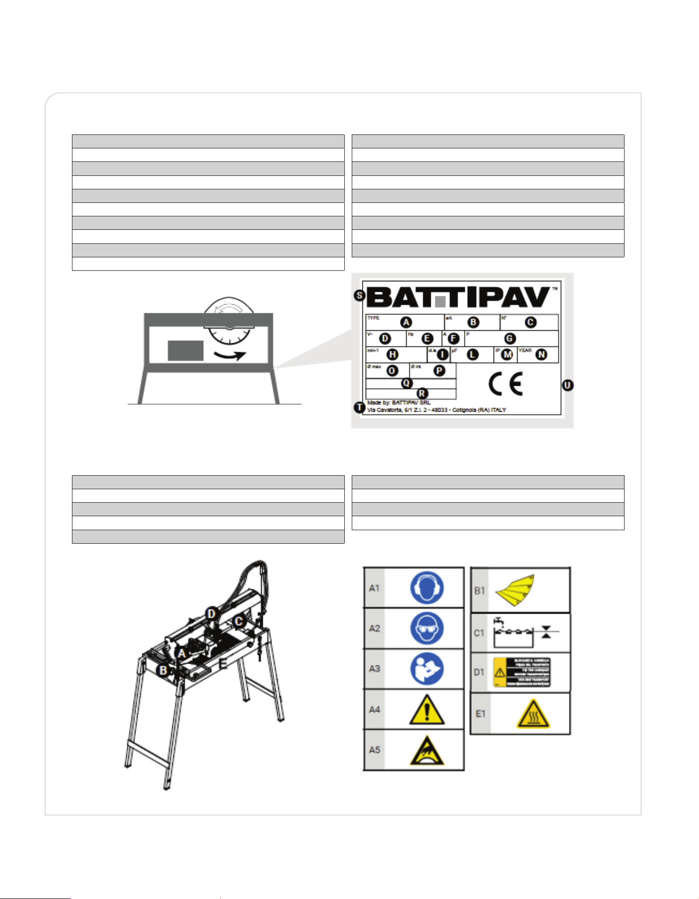
A Machine Model
B Item
C Serial Number
D Power Supply Voltage
E Power Supply Frequency
F Current Absorption
G Installed Power Rating
H Tool Rotation Speed
I Class of Protection
L Starter Capacitor
M IP Level
N Year of Manufacture
O Max Tool Diameter
P Internal Tool Diameter
Q Accessories
R Accessories
S Manufacturer's Name
T Manufacturer's Name & Address
U Certication Marks
The name plate shown is tted directly on the machine. It indicates all the references and information necessary
for safety operation.
TECHNICAL DATA LABEL / SYMBOLS & SIGNS
SYMBOLS AND SIGNS
Danger / Prohibition stickers are applied to the machine where necessary.
Look at these prior to using the machine.
A1 Obligation to Use the Prescribed PP E (Protective Earmuffs)
A2 Obligation to Use the Prescribed PPE (Protective Glasses)
A3 Read the Instructions Before Each Use
A4 General Warning Sign
A5 Risk of Cutting
B1 Cut Setting 45°
E1 CAUTION Hot Surface - Risk of Burns
C1 Recovery Tank Water Level
D1 WARNING! Secure the Carriage

22
ENVIRONMENTAL SPECIFICATIONS OF USE & STORAGE
TRANSPORTATION
ENVIRONMENTAL SPECIFICATIONS FOR USE AND STORAGE REQUIREMENTS
Use the machine in compliance with the following environmental conditions:
• Ambient temperature between 5°C and 45°C.
• Relative humidity of air, maximum: 60% (without condensation).
• Altitude 1000 m.
STORAGE AND TRANSPORT REQUIREMENTS
The machine and all it accessory parts must be stored and transported in compliance with the following conditions:
• Do not store outdoors.
• Store in a dry and dust-free place.
• Do not expose to aggressive agents.
• Protect from solar radiation.
• Avoid mechanical vibrations.
• Storage and transport temperature range between -25° and +55°C.
• Relative humidity of air, max 60%.
In case of storage for more than 3 months, regularly check the general storage conditions of all parts and packaging.
THE 49” BRIDGE SAW MACHINE IS EASY TO CARRY BY USING THE SIDE HANDLES.
BEFORE CARRYING THE MACHINE MAKE SURE THAT:
• The motor carriage is locked in place with the two cutting adjustment knobs on the slide rail.
• The motor carriage is completely lowered and locked with the locking lever.
• The machine is in the 45° position and the adjustment knobs are properly tightened.
• The water tube-holder rod is out of its housing.
• The legs are folded underneath and secured with the locking pin.
23
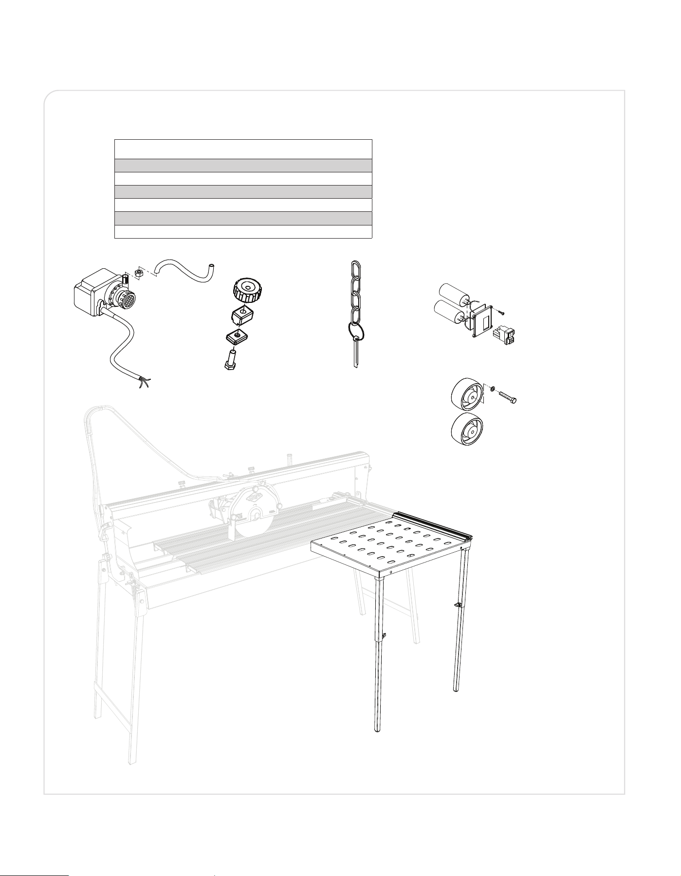
REPLACEMENT PARTS LIST
PART DESCRIPTION PART #
Extension table 83249-01
Water pump 83249-02
Thumbscrews 83249-03
Locking Pin 83249-04
Wheels 83249-05
Switch (ON / OFF) 83249-06
Water Pump
Extension table
Thumbscrews Locking Pin Switch (ON / OFF)
Wheels
24
Boca Raton, FL 33487
E2625-12554
Customer Service
1-866-435-8665 (toll free)
Monday — Friday, 8:00 AM to 5:30 PM EST
qep.com
EC DECLARATION OF CONFORMITY
BATTIPAV S.R.L. (Z.I.2 Via Cavatorta 6/1 - 48033 Cotignola (RA) ITALY Tel 0545 40696 - info@battipav.com -
www.battipav.com) Declares under your sole responsibility that the product:
Model: 49” BRIDGE SAW
Art.: 83249
Model: 49” BRIDGE SAW site cutter is a machine intended specically for cutting ceramics, single-red items,
terracotta, marble, cement, natural stones, refractory materials.
This Declaration relates to the following Directives:
2006/42/EC (MD), 2014/35/EU (LVD), 2014/30/EU (EMC), 2011/65/EU (RoHS II)
Reference to harmonized standards: EN12418:2021, EN60204-1:2018, IEC60204-1:2016/AMD1:2021
EN60335-1:2012+A11+A13+A1+A14+A2+A15, EN IEC60335-2-41:2021+A11, CEI EN 61000-6-1:2007,
CEI EN61000-6-3:2007+A1:2013, CEI EN 61000-3-2:2015, CEI EN 61000-3-3:2014, EN ISO20607
General Manager
Stefano Tondini
NOTES