Brand: GOYOJO
Product name: Viscostmeter
Model: NDJ-8S
Manufacturer: GOYOJO Industrial Technology(shenzhen) Co., Ltd
Address: Shenlan,No.1Lianteng Road, Guangming District,Shenzhen city,
Guangdong Province,518107,China
E-mail: sign2@goyojo.com
Skype/ph/whatsapp: +8619924549574

Dear user,
Thank you very much for purchasing our
viscometer. To enable you to use this product
correctly, please read this manual carefully
before use.
Thank you!
This operation manual is applicable to several types of
viscometers, please read it according to the machine
type or configuration youve purchased!
2.Main Features and Technical Indexes
3.Structure and Installation of the Instrument
4.Installation and Use of Instrument
5.Auto Search Function
6.Precautions
Contents
01
01
02
03
8.Guarantee
1.Overview & Operating Principle
7.Appendix: #0 Rotor Setup
05
06
08
10
The NDJ Monochrome Screen Viscometer is a microcontroller-based
intelligent device using a high-performance ARM processor, angle-free
imported stepper motor, and actuator. The motor drives a rotor through a
torque sensor at constant speed. When the rotor encounters viscous
resistance in the liquid, the sensor converts this force into electrical
signals, which are processed by dedicated software to display viscosity on
the LCD screen. This instrument offers:
ARM-powered precision control
User-friendly interface with intuitive readings
Automatic range calibration for high accuracy
Wide applications in adhesives, latex, paints, cosmetics, and more
I. Overview and Operating Principle
1.Intuitive Interface: Displays viscosity, temperature (with probe), and
% full scale.
2.Data Software (Optional): Real-time viscosity curve plotting for non-
Newtonian fluids.
3.Accessories: Temperature probe, water bath, micro printer, and
calibration fluids available.
II. M ain Features and Technical Indexes
NDJ-8S
10 mPa. S - 2,000,000 mPa. S
(1 mPa. S = 1 CP = 0.001 Pa. S)
± 3%
#1, #2, #3, #4 rotors (#0 rotor is an
optional part)
0.3, 0.6, 1.5, 3, 6, 12, 30, 60 RPM
95×130×155mm (the base excluded)
2 KG (the base excluded)
Measurement range
Measurement accuracy
Rotor specification
Rotating speed
Overall dimensions
Net weight
Model
III. Structure and Installation of the Instrument
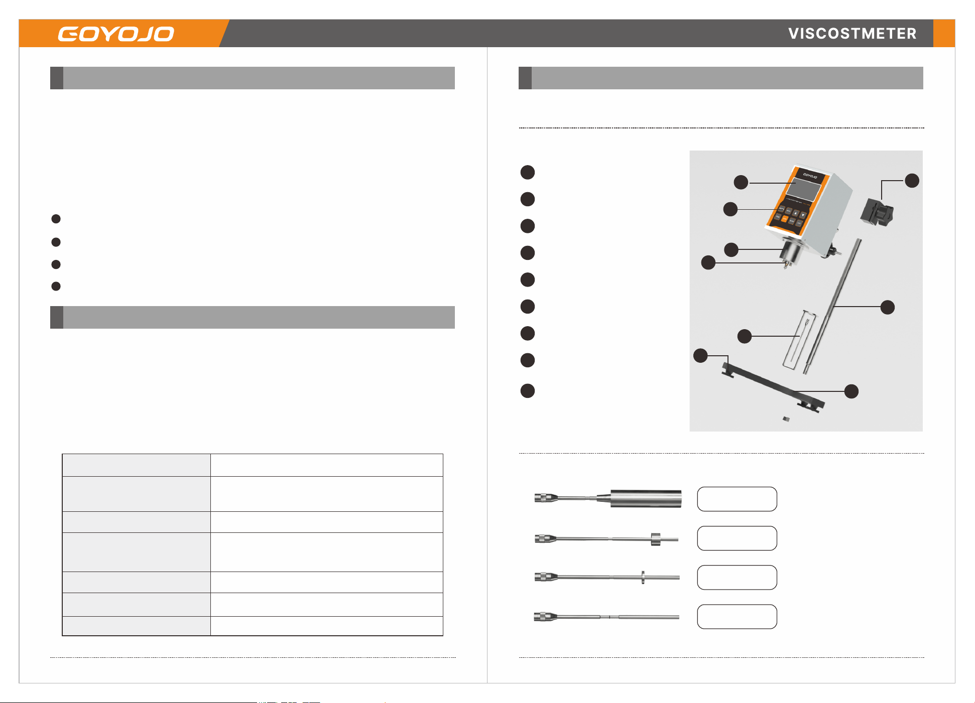
1.The structure of the instrument is shown in the figure below
1
2
6
3
7
8
5
4
9
Level bubble
Liquid display screen
Outer cover
Rotor protection rack
Base for the main machine
Operating keyboard
Rotor connector
Rotor
Horizontal adjustment
knob of the base of the
main machine
1
2
3
4
5
6
7
8
9
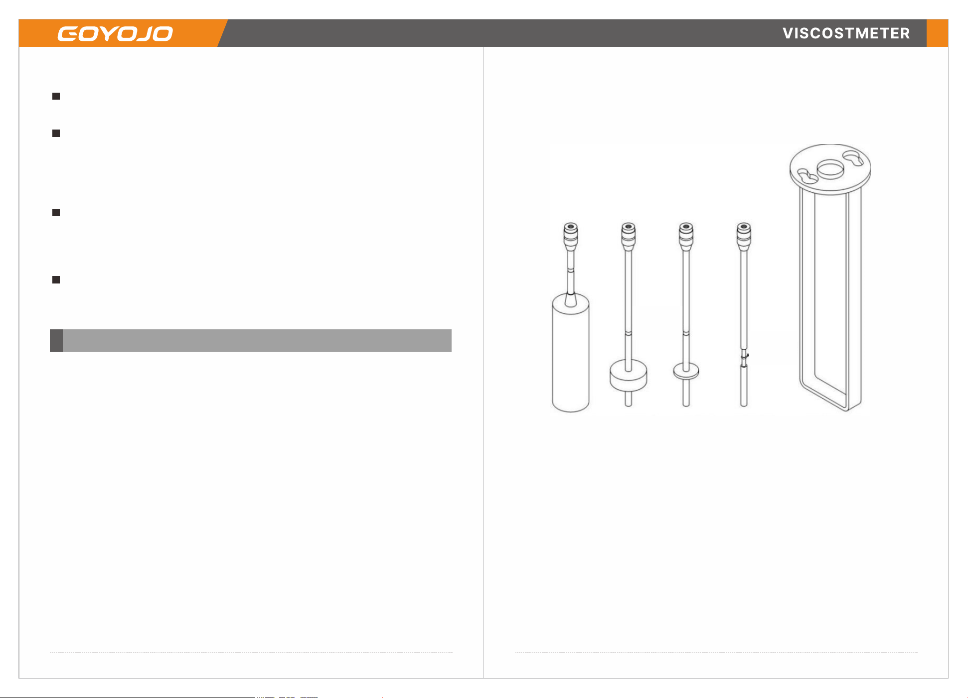
# 1 rotor
# 2 rotor
# 3 rotor
# 41 rotor
-2--1-
2. Installation of the instrument
Remove the base, lifting column, viscometer main unit, power adapter,
rotors, and other components from the packing container in sequence.
Insert the lifting column into the base's hole and secure it with nuts
(Note: Position the lifting knob on the right side with the toothed bar
facing you). Rotate the lifting knob to adjust the tension until the main unit
stays stationary without sliding and the resistance feels smooth. If it's too
loose or tight, adjust the front of the slider by turning the adjusting screw.
Insert the instrument's main unit handle connecting rod into the lifting
slider's mounting hole. Straighten it and tighten the fixing knob. Then
adjust the three base feet to center the horizontal bubble within the black
circle on the instrument top.
Remove the shipping protective cap beneath the instrument casing.
Verify the power supply meets operational requirements, switch it on, and
the installation is complete.
IV (1). Installation and Use of Instrument
Prepare approximately 400 mL of the sample liquid and transfer it to a
beaker or straight-sided cylindrical container with a minimum diameter of
60 mm and height of 120 mm. Preferably use a water-circulating container
to precisely control sample temperature via a thermostatic water
bath. Note: Viscosity is temperature-dependent—the higher the
temperature, the lower the viscosity.
1. Panel Controls
The instrument features eight keys: "Rotor Selection," "Quick Setting," "▲"
"▼" "Start" "Stop" "Auto Search" and "OK.”
2. Power On & Parameter Setup
The instrument features eight keys: "Rotor Selection," "Quick Setting," "▲"
"▼" "Start" "Stop" "Auto Search" and "OK.”
3. Screen Readouts
Third Line: Displays the maximum measurable viscosity for the current
rotor/speed combination.
Fourth Line: Temperature reading (available only when a temperature probe is
connected).
4. Rotor Positioning
After confirming parameters, attach the selected rotor to the instrument.
Slowly adjust the lifting knob to lower the rotor into the sample until the
rotor’s liquid level mark (center groove) aligns with the liquid surface. See
figure below for reference.
Liquid
level
marker
Liquid
level
marker
# l rotor #2 rotor #3 rotor #4 rotor Rotor protection
4. Horizontal Alignment
Adjust the horizontal bubble on the instrument top to ensure it remains
centered, confirming the instrument operates level.
5.Measurement Procedure
Press "Start" to begin measurement and monitor the percentage (%) value on
the screen.
Maintain readings between 10%–95% for accuracy, with 50% ideal. If outside
this range:
Modify rotor/speed combination to extend/reduce measurement range.
Lower percentages indicate higher viscosity; increase percentages for lower
viscosity.
-4-
-3-
The Auto Search function is a quick reference for customers who have no
idea how to select "Rotor" or "Speed".
Install the rotor corresponding to the one on the screen, and press
"Speed Setting" and then press "Auto Search" and "Start" to enter the state
of automatic testing.
At this time, the customer just needs to wait for the prompt instead of
operating the instrument. If the percentage (%) value is between 10% and
95%, the instrument will initially set the rotor and speed used at this time
as appropriate. And press "Stop" twice continuously to exit from this
function.
According to the percentage values provided above, make a fine
adjustment on the speed, and it will be the best state if the percentage (%)
value is 50%. (Note: It doesn't have to be exactly 50%, and it's also OK if
the value is between 30% and 60%)
6. Viscosity Estimation & Setup
When unknown, assume high viscosity:
Start with small rotors (higher numbers) and slow speeds.
Gradually increase rotor size (lower numbers) or speed for lower-viscosity
samples.
Start with small rotors (higher numbers) and slow speeds.
Gradually increase rotor size (lower numbers) or speed for lower-viscosity
samples.
7. Data Collection
Once readings stabilize, press "Stop" to record results.
Press "Stop" again to return to standby mode.
IV (II) Auto Search Function
IV (III)
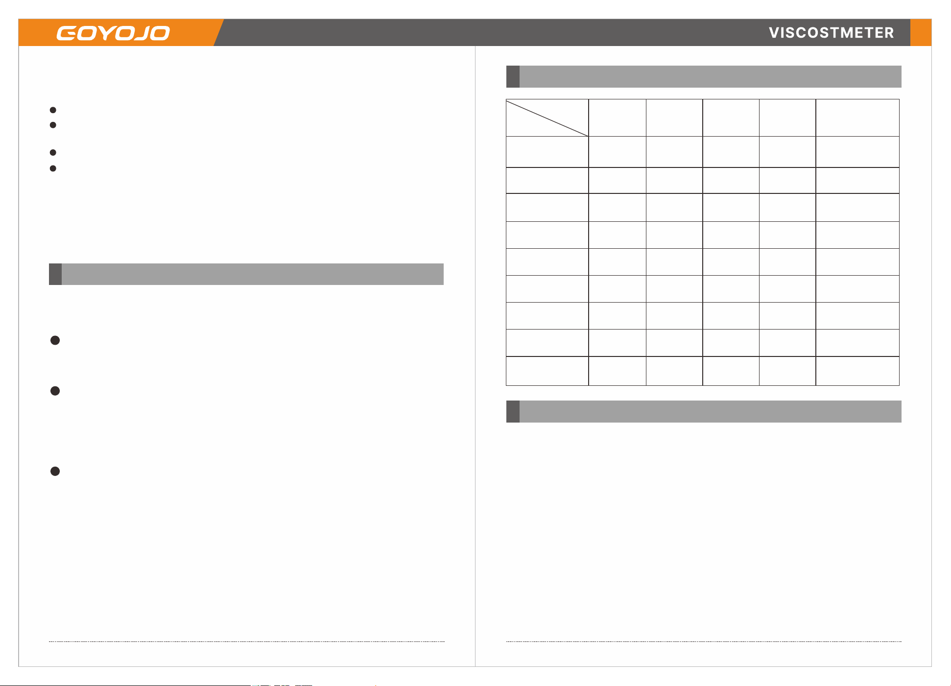
Rotor
Speed
0.1 RPM
0.3 RPM
0.6 RPM
15 RPM
3 RPM
6 RPM
12 RPM
30 RPM
60 RPM
#0 #1 #2 #3 #4
20
10
60000
20000
10000
4000
2000
1000
500
200
100
300000
100000
50000
20000
10000
5000
2500
1000
500
1200000
400000
200000
80000
40000
2000
10000
4000
2000
6000000
2000000
1000000
400000
200000
100000
50000
20000
10000
V. Precautions
1. As The instrument is strictly calibrated and tested before leaving
the factory, it can work normally after startup. Please read this
manual for the instrument carefully before operation, and the
operation shall be in strict accordance with the requirements.
2. The power supply of the instrument must be measured within the
specified range of voltage and frequency errors, otherwise the
measurement accuracy will be affected.
3. Handle the rotor with care during the installation and removal of
the rotor, lift the universal joint slightly upward for removal and
installation. Do not exert too much force and do not make the rotor
subject to horizontal force, so as to avoid bending the rotor. The end
face and thread of the connection of the universal joint and rotor
should be kept clean, otherwise it will affect the correct connection
-6--5-
of the rotor and the stability of rotation.
4. Do not start the instrument when there is no liquid after the
rotor is installed, so as to avoid damage to the pivoting point and
bearings.
5. Clean the rotor timely after use. Remove the rotor for cleaning, and
it is strictly forbidden to clean the rotor on the instrument. And the
rotor should be properly put in the storage box after cleaning.
6. Cover the instrument with the black protective cap when moving
and transporting the instrument (Note: The protective cap must be
removed before it is powered up).
7. Do not disassemble and adjust the parts and components of the
instrument, and do not lubricate the instrument by yourself.
8. Most of turbid liquids, emulsions, high polymers and other high
viscosity liquids are "non-Newtonian liquids", and their apparent
viscosity often varies with shear speed, rotor and time. Therefore,
when measured under different rotors, speed and time, the results
may be inconsistent, which is a normal situation and does not mean
that the instrument is inaccurate. Generally, non-Newtonian liquid
should be measured with rotor, speed and measurement time.
9. Do not put the instrument sideways or laterally.
10. The more correct value can be obtained if the operator can comply
with the following requirements for measurement
A Precisely control the temperature of the measured liquid
B Immerse the rotor in the measured liquid for a long enough
period of time and maintain it at constant temperature, so that it will
be consistent with the temperature of the measured liquid.
C Ensure the evenness of the measured liquid
D Try to put the rotor at the center of the container
E Usually, a large rotor and fast speed are selected for the liquid
with low viscosity; and a small rotor and slow speed are selected for
the liquid with high viscosity
F Ensure the cleanness of the rotor
G Prevent bubbles from adhering to the bottom of the rotor when it
is immersed in the measured liquid
Packing List
I. Complete set of the instrument
1. NDJ series viscometer (main machine) 1 set
2. Lifting bar and base 1 pcs for each one
3. Protection rack 1 pcs
4. Rotors 1 set
5. Power adapter 1 pcs
6. Operation Manual 1
7. Qualification certificate 1
8. Warranty card 1
Appendix 1.
Installation and Use of #0 Rotor
I. #0 Rotor System(Additional separate purchase required, not
included in the package)
The #0 rotor must be used as part of a dedicated kit consisting of the
bracket, fixed test bucket, hook, and #0 rotor. This kit is exclusive to
the #0 rotor and cannot be used with other rotors after testing.
II. Assembly Steps
Attach the #0 rotor bracket to the instrument’s lower casing.
Secure the rotor head and #0 rotor to the universal joint.
III. Sample Preparation
Pour approximately 30 mL of sample fluid into the test bucket.
IV. Test Setup
Gently position the fluid-filled test bucket into the fixed bracket from
-8-
-7-
the bottom up.
Secure it with the test bucket set screws (Note: Ensure no contact
between the test bucket and rotor during installation).
Level the instrument using the horizontal bubble before proceeding
with measurements.
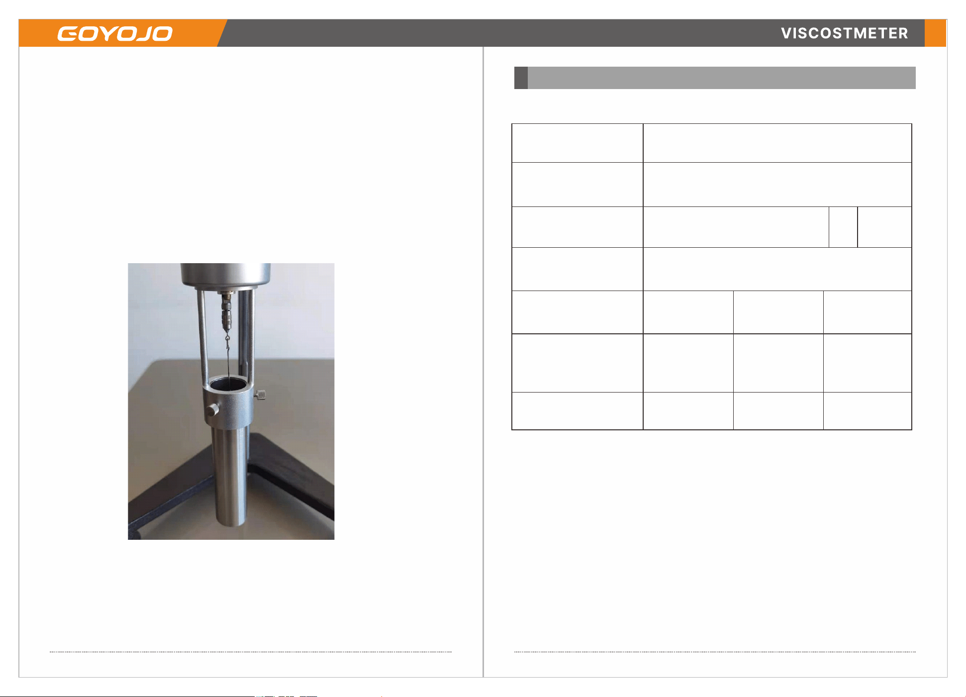
V. Reference Image
The complete assembly is illustrated in the figure below.
Users files: Date.
User name
Address
Telephone
Purchasing address
Retail price
Commodityname
and specification
Dealer Signature
Odd Numbers
Model No.
User Signature
Zip
Guarantee ltem
1. 3months upon date of purchase,if there is function problem, we
should offerthe same item subject to goods and packing maintain
perfect
2. 1year upon date of purchase we will guarantee to keep the goods in
repair,(excluding fittings)
3.Guarntee service is subject to normally using.
4. All of damage by man-made (tear open the housing, tear off the
sticker,unnormally using),or losing this card,we will not guarantee
Guarantee
-10-
-9-