PORTABLE PCP AIR
COMPRESSOR
Operating Instructions
Product name: Portable PCP Air Compressor
Manufacturer: GOYOJOIndustrialTechnology(shenzhen)Co.,Ltd
Address: Shenlan,No.1LiantengRoad,GuangmingDistrict,Shenzhencity,
GuangdongProvince,518107,China
E-mail: sign2@goyojo.com
Skype/ph/whatsapp: +8619924549574
GAC-S1
FCC Compliance Information (USA Only)
Caution:
Any changes or modifications not expressly approved by the party responsible
for compliance may void the user's authority to operate this equipment.
This device complies with Part 15 of the FCC Rules. Operation is subject to the
following two conditions:
This device may not cause harmful interference, andThis device must accept any
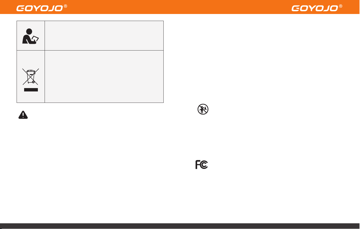
Warning – Safety First
To reduce the risk of injury or equipment damage, please
read this instruction manual carefully before operating
the unit.
Proper Disposal
1. This product is subject to the European Directive
2012/19/EU on Waste Electrical and Electronic
Equipment (WEEE). The symbol of a crossed-out
wheeled bin indicates that this product and any of its
marked accessories must be disposed of separately
from household waste.
2. Please take it to an appropriate collection point for
the recycling of electrical and electronic equipment.
Important Safety Precautions
• The GOYOJO Portable PCP Air Compressor can operate on either 115V/230V AC
(selectable voltage) or 12V DC vehicle power. Cables for both power options
are included.
• Never operate the compressor without first turning on the cooling fan.(Note:
This unit is designed so that the fan starts automatically when plugged in and
cannot be turned off manually. This prevents accidental overheating due to
forgetting to activate the cooling system during operation.)
• This compressor is specifically designed for filling airguns equipped with an
integrated air cylinder or buddy bottle, with a capacity of up to 1 liter (1000cc).
• To avoid overheating, it is recommended to allow the compressor to rest for
10 minutes after every 25 minutes of continuous operation.
• Do not use this compressor to fill SCUBA tanks or any air containers larger
than 1 liter.
• Improper use or misuse may damage the compressor or your PCP airgun.
Such damage is not covered under warranty.
• While the compressor's maximum output is 300 BAR (4,500 PSI / 30 MPa),
always follow your airgun manufacturer's recommended fill pressure and
never exceed its rated limit. It is also recommended to stop charging once
pressure reaches 280 BAR (3,750 PSI / 28 MPa) to allow a safe margin.
• Always monitor the pressure on both the PCP airgun’s pressure gauge and the
compressor’s built-in gauge simultaneously during operation.
• To prevent overheating, only operate the compressor in a well-ventilated
environment.
• Always observe standard safety procedures when filling your PCP airgun.
• If the power cord is damaged, it must be replaced with a special cord or
assembly available from the manufacturer or an authorized service agent.
• Before inflation, ensure that the bleed valve is fully tightened and the air
cylinder is properly sealed. Once the compressor automatically stops after
reaching the target pressure, always release the pressure via the bleed valve
before disconnecting the fill hose — this step is critical for safety.
Usage by Children and Vulnerable Persons
1. This appliance may be used by children aged 8 years and older, and by
persons with reduced physical, sensory, or mental capabilities or lack of
experience and knowledge, only if they are supervised or have been
instructed on safe use of the appliance and understand the associated risks.
2. Children must not play with the appliance.
3. Cleaning and routine maintenance must not be carried out by children
without supervision.
interference received, including interference that may cause undesired
operation.
Warning:
Modifications to this product not approved by the responsible party may result in
loss of compliance with FCC regulations and void the user's right to operate the
device.
Note:
This product has been tested and found to comply with the limits for a Class B
digital device, pursuant to Part 15 of the FCC Rules. These limits are intended to
provide reasonable protection against harmful interference in residential
installations.
This equipment generates, uses, and can radiate radio frequency energy. If not
installed and used in accordance with the instructions, it may cause harmful
interference to radio communications. However, there is no guarantee that
interference will not occur in a particular installation.
If interference does occur, which can be determined by turning the unit off and
on, the user is encouraged to try the following measures to correct the issue:
• Reorient or relocate the receiving antenna.
• Increase the separation between the device and the receiver.
• Connect the device to a power outlet on a circuit different from the one the
receiver is connected to.
• Consult your dealer or an experienced radio/TV technician for assistance.
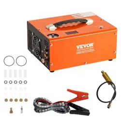
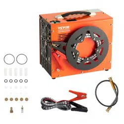
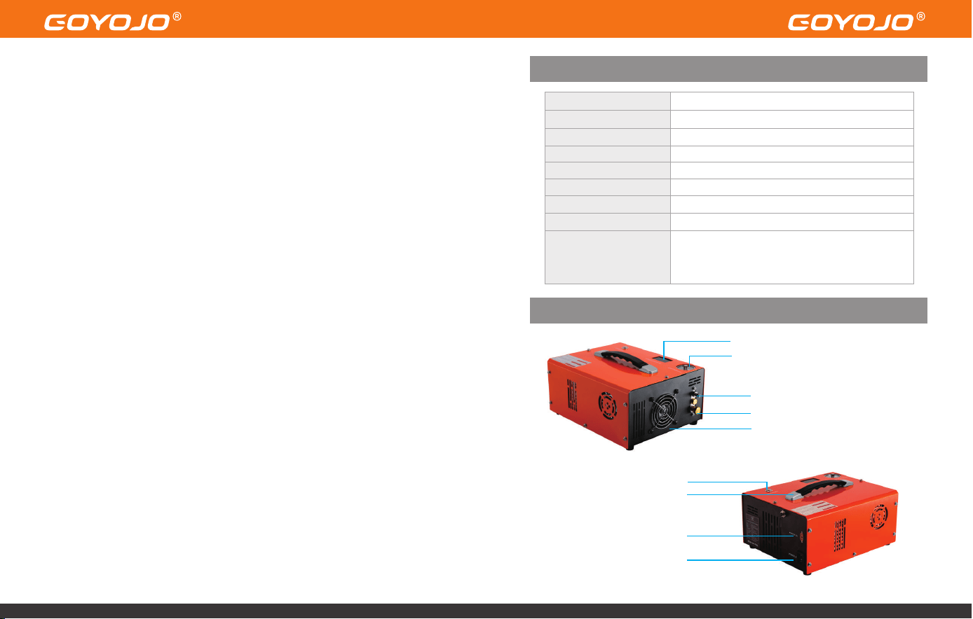
Product Specifications
Product Appearance
Temperature Indicator
Pressure Gauge
High Pressure Air Outlet
Bleed Valve
High-powerCooling Fan
Inflate Button
Sturdy Handle
12V DC Power Socket
AC Power
Brand
Model
Operating Voltage
Power Output
Maximum Pressure
Shut-off Mode
Cooling System
Included Accessories
GOYOJO
GAC-S1
DC 12V (vehicle battery) / AC 115V/230V
300W
4,500 PSI / 30 MPa
Automatic Stop
Built-in Fan Cooling
Power Cord ×1
8mm Connector ×1
Spare Parts Kit ×1
Alligator Clips ×1
User Manual ×1
Product Size 4.921inX11.02inX8.6in(2.5cmX28cmX22cm)
Operating Instructions – Getting Started
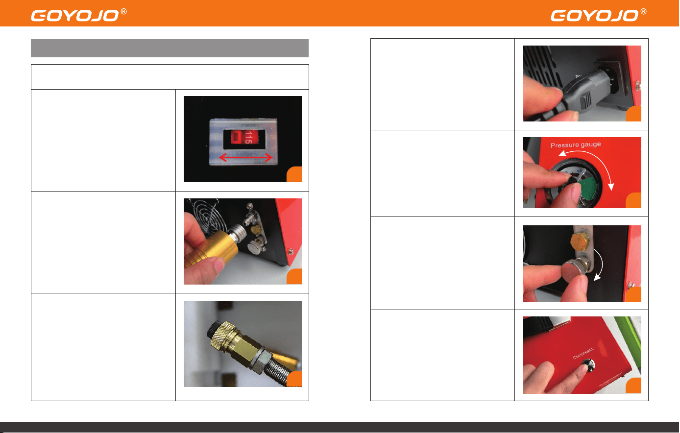
1.Check the Operating Voltage
Before use, inspect and confirm the
correct working voltage by checking
the selector switch located on the
bottom of the compressor. Ensure it
matches your power source.
Before Inflation (Testing Compressor Functionality)
2.Attach the Hose to the Compressor
Output
Connect the hose (fitted with a male
Foster connector) to the air output
port on the front of the compressor.
Ensure the coupling is properly and
tightly locked in place.
3.Connect the Fill Hose and Block
the Outlet
Seal the other end of the hose using
an air-blocking plug.
4.Connect to Power Supply
Plug the included AC power cord
into the power port on the right-
hand side of the compressor. Then
plug the three-prong plug into a
wall outlet that matches the
selected voltage.
5.Set the Auto Shut-Off Pressure
Manually rotate the needle on the
automatic shut-off pressure gauge
to set your desired pressure level.
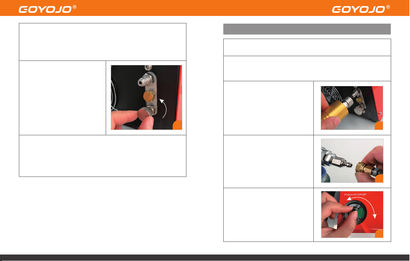
6.Tighten the Bleed Valve
Turn the air bleed valve on the front
of the unit clockwise to close it.
7.Press the Inflation Button
Press the power/inflation button to
start the compressor. The unit will
begin to pressurize the sealed
system.
1
2
3
4
5
6
7
8.Automatic Shut-Off at Target Pressure
Once the preset pressure is reached, the compressor will automatically stop.
(Note: The cooling fan will continue running to help dissipate heat—this is
normal.)
9.Release Pressure Before
Disconnecting
After inflation is complete, always
open the bleed valve to release
pressure. Wait until the pressure
gauge needle returns to zero,
indicating full depressurization.
Only then remove the air-blocking
plug to proceed with actual filling.
• If all steps above are completed successfully, it indicates the
compressor is functioning correctly. You may now proceed to charge
your intended air cylinder.
• Connect to Your PCP Airgun or Cylinder
Charging Your PCP Airgun or Cylinder
1.Check for Airtightness, Then Connect the Fill Hose
Inspect your air cylinder or PCP airgun to ensure proper sealing.
Once functionality testing is complete, you may begin actual
charging:
2.Attach the Hose to the Compressor
Output
Connect the hose (fitted with a male
Foster connector) to the air output
port on the front of the compressor.
Ensure the coupling is properly and
tightly locked in place.
4.Set the Auto Shut-Off Pressure
Manually rotate the needle on the
automatic shut-off pressure gauge
to set your desired pressure level.
9
4
2
3.Attach the quick-connect female
coupler on the fill hose to the air inlet
of your PCP airgun, air bottle, or
airsoft product.
Ensure the connection is secure and
leak-free.
3
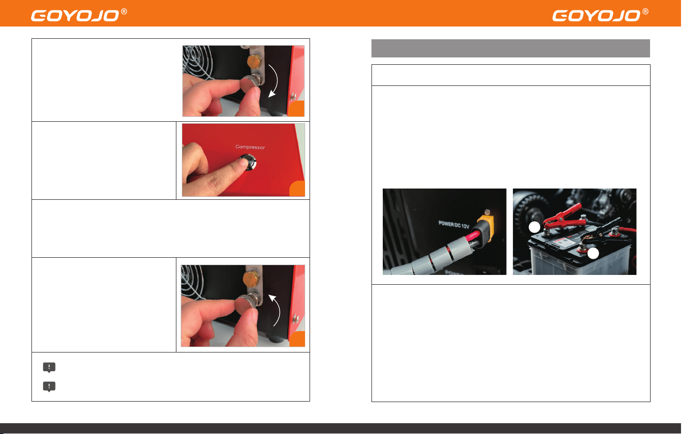
6.Start the Compressor
Press the POWER button on the top
of the unit.
The compressor will start operating
and begin filling the connected air
cylinder.
Using a 12V Car Battery (DC Mode)
1.Ensure your vehicle’s engine is running before powering the unit.
2.Connect the supplied DC power cable to the 12V socket on the right side
of the compressor.
3.Attach the red alligator clip to the positive (+) terminal of your car
battery.
4.Attach the black alligator clip to the negative (–) terminal.
The remaining steps are the same as above.
DC Power Connection Steps:
7.Automatic Shut-Off at Target Pressure
The compressor will automatically stop once the preset pressure is reached.
(Note: The cooling fan will continue running to dissipate residual heat — this
is normal behavior.)
8.Release Pressure Before
Disconnecting
After inflation is complete,
always open the bleed valve to
release internal pressure.
Wait until the pressure gauge needle drops to zero, indicating full
depressurization.
Only then disconnect the fill hose from the airgun or cylinder.
Important Notes on Temperature & Auto Shut-Off
If the compressor temperature exceeds 80°C (176°F), you must manually
stop the compressor:
• Press the POWER button to stop compression.
• Keep the cooling fan running to aid heat dissipation.
• Once the unit cools down, you may restart the compressor.
• To protect the motor, the compressor features an automatic 30-minute
shut-off
6
7
+
-
5.Close the Bleed Valve
Turn the bleed valve on the front
of the unit clockwise to close it.
Finger-tight is sufficient — do not
overtighten.
5
Routine Maintenance
Note:
We recommend performing routine maintenance after filling approximately 50
bottles (500cc each) or after 20 cumulative hours of use, whichever comes first.
This includes cleaning debris and replacing worn O-rings.
WARNING:
Always disconnect all power sources before performing any maintenance!
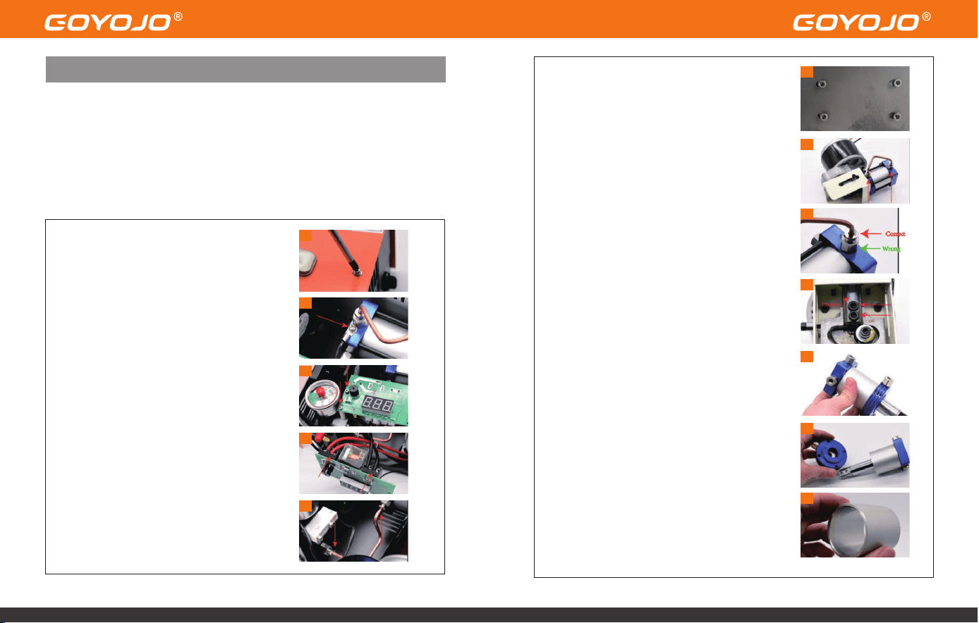
Disassembly & Cleaning Steps
1.Remove the Metal Housing
Loosen all 12 screws on the compressor
housing:(5 on the front, 5 on the back, 2 on the
top)
Carefully lift off the metal casing — handle
gently to avoid damaging internal wiring.
2.Disconnect the Temperature Sensor Wire
Unscrew the sensor cable from the cylinder.
3.Detach Display Screws
Loosen the 2 screws located on the left side of
the display module.
4.Disconnect Power Wires from Motor
Loosen the 2 screws securing the red (OUT +)
and black (OUT –) motor wires.
5.Remove Condensation Tube Screws
Loosen the 2 screws connected to the
condensation tube.
6.Remove the Motor Screws
Unscrew the 4 base screws holding the motor
to the compressor frame.
7.Detach Condensation Tube from Cylinder
With the motor and cylinder assembly
removed, unscrew the 2 screws securing the
tube to the cylinder.
8.Loosen the Smaller Outer Screw
Important: Only loosen the smaller outer
screw, not the larger one.
9.Remove the Piston Rod Screws
Use a hex key to remove the 2 black screws on
the end of the piston rod.
10.Detach Cylinder Head
Unscrew the 4 top screws on the cylinder to
remove the entire cylinder head assembly.
11.Clean Round Metal Parts
Remove the round metal component, clean
any dirt, and inspect for damaged O-rings.
Apply a thin layer of silicone or engine oil to
the inner O-rings if needed.
12.Clean Column Metal Part
Remove and clean this part thoroughly. Re-
lubricate the interior surface with silicone or
engine oil.
1
2
3
4
5
6
7
8
9
10
11
12
13.Separate Piston Assembly
Detach the piston from the square metal part,
clean all components, and check for O-ring
damage.
It's normal if the light gray O-ring appears
broken—this part is designed to wear with
time.
14.Clean the Inside of the Square Block
Remove any dirt or buildup inside the square-
shaped metal housing.
15.Clean the One-Way Metal Sheet
Loosen the screw holding the one-way valve
plate, clean the area, and re-tighten the
screw.
IMPORTANT: Do not over-tighten this screw.
Air must be able to exit through this section.
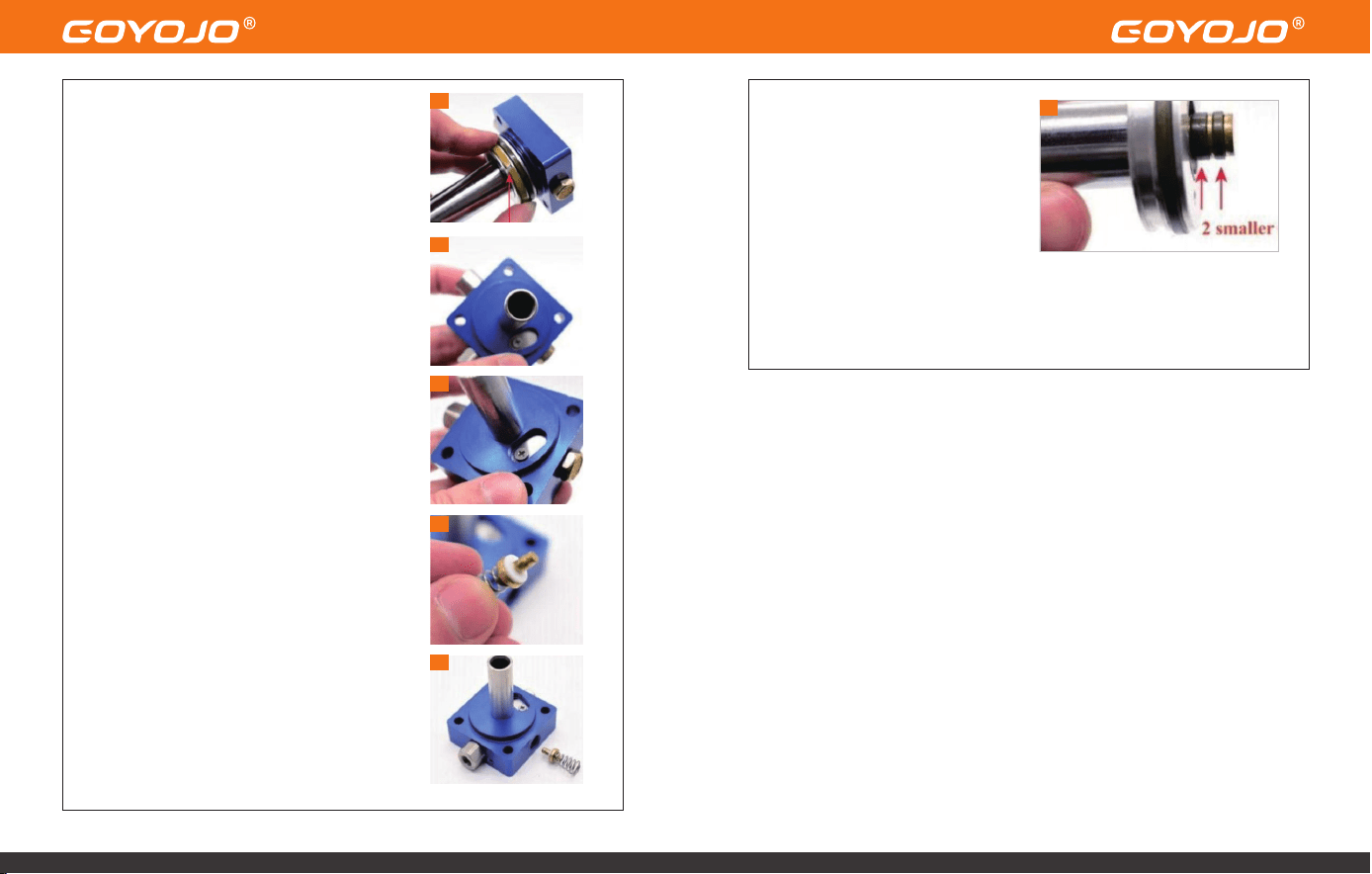
16.Clean the One-Way Valve
Unscrew the one-way valve cap and remove
the valve and spring.
Clean thoroughly and check for damage.
17.Reassemble One-Way Valve
When reassembling:
The metal valve face should be inward,
The spring should face outward.
Lightly tighten the cap screw.
18.Inspect and Lubricate Piston O-
Rings
Check all piston O-rings for
damage or wear.
Apply a thin coat of silicone or
engine oil to the two small O-rings.
Maintenance Complete!
To ensure proper reassembly, we recommend watching the instructional
video during the process:
Watch Here: https://youtu.be/jeKo7dqSfnM
13
14
15
16
17
18
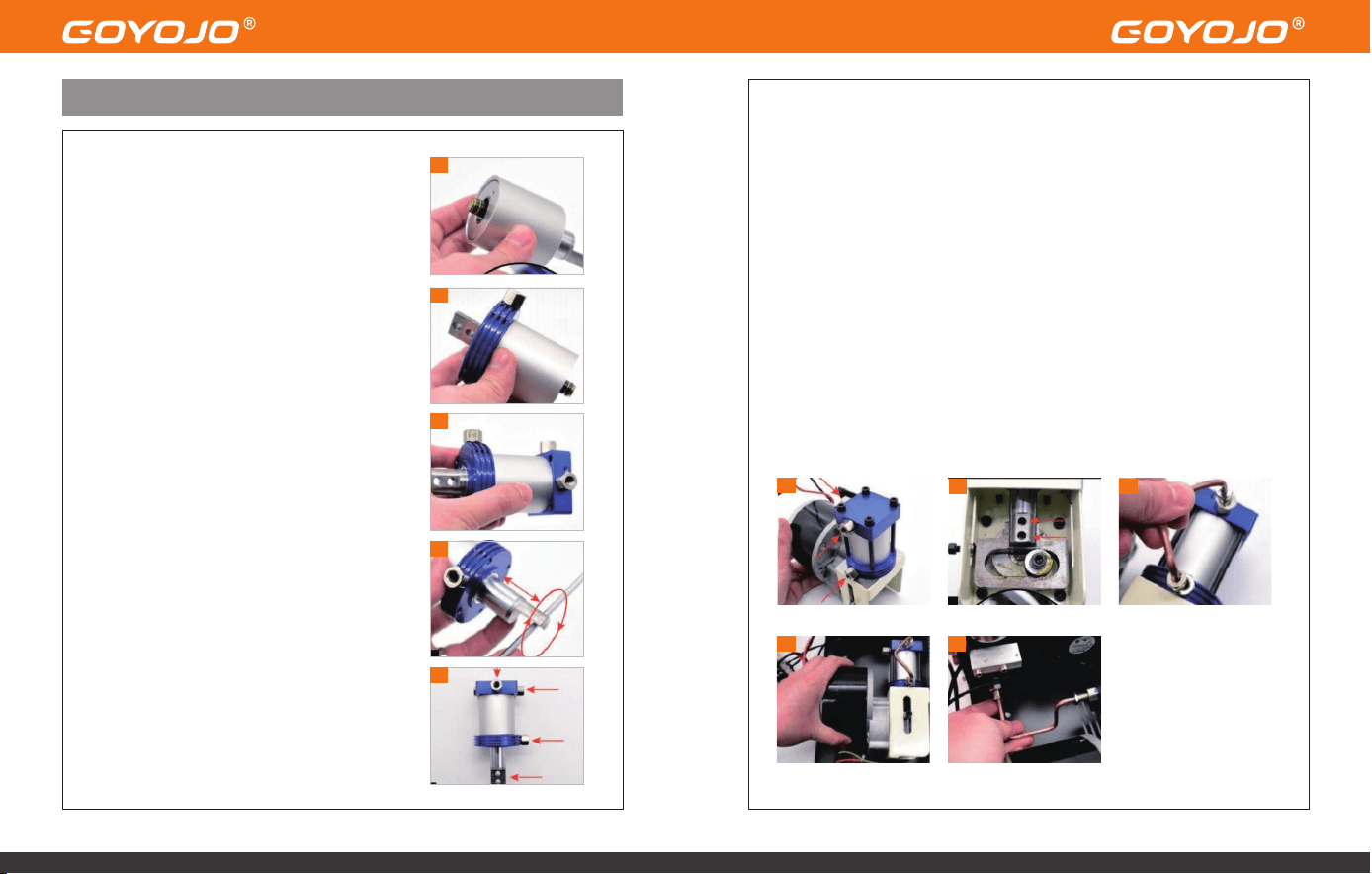
6.Mount the Cylinder to the Motor
Align and fasten the cylinder to the motor using four black screws.
Pay attention to the direction of the three red-arrow-marked screws as
incorrect orientation may affect performance.
7.Secure the Piston Rod
Use two black screws to connect the piston rod to the motor rod.
Tip: You may gently rotate the motor screws with a hex key to align the
holes for easier screw insertion.
8.Install the Condensation Tube onto the Cylinder
9.Reinstall the Motor and Cylinder Assembly
Place the assembly back into the compressor base and tighten four black
screws at the bottom.
Assembly Instructions
1.Insert the Piston into the Column
Place the piston into the column metal part.
Ensure the bottom of the piston sits flush with
the base of the column.
2.Install the Round Component
Insert the round-shaped metal part into the
column.
3.Install the Square Component
Attach the square-shaped part to the opposite
end of the round part.
Ensure tight contact with no visible gaps
between components.
4.Lubricate Internally
Gently move the piston back and forth and
rotate it using a tool.
Repeat this motion 3–4 times to distribute
internal oil evenly.
5.Align Components for Assembly
Rotate the square part, round part, and piston
to align them as shown in the reference
diagram (Step 3.5).
Ensure all screws and the piston rod are facing
the correct direction.
Pull the piston rod to its fully extended position.
1
2
3
4
5
6
7
8
9
10
Troubleshooting – Error Codes
CODE DESCRIPTION
E0
E1
E2
E3
E4
Temperature sensor malfunction.
Automatic shutdown triggered when temperature
exceeds 85°C.
Input voltage too low (below 9.8V).
Pressure setting button failure.
Automatic shutdown due to maximum working time
reached or target pressure achieved.
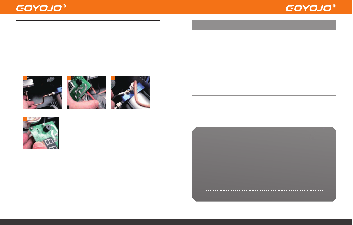
10.Install the Second Condensation Tube
11.Reconnect Motor Wires to Display Panel
Connect the red wire to OUT+ and the black wire to OUT–.
12.Reconnect the Temperature Sensor Wire Secure it back to the cylinder.
13.Reinstall the Display Panel
10
11
12
13
Thank you for choosing GOYOJO.
We sincerely appreciate your trust in our product. If you encounter any
issues during use, please don’t hesitate to contact us by email at
sign2@goyojo.com. Our support team will review your concerns and
assist you in resolving the problem as quickly as possible.
We also welcome any feedback or suggestions for
improvement—your input helps us continue to grow and serve you
better.
Thank You