Document No. :
NQR.CP-M5-2401-001
Shenzhen Navynav Technology Co.,Ltd.
Addr:Rm 502,Han’s Laser Technology Centre, Shennan Ave No.9988,Nanshan District, Shenzhen,P.R.C
www.navynav.com
M7
Product Specification
Document No.: NQR.CP-M5-2401-001
Product Model:
M7
Product Name:
Built-in transceiver and data
transmission radio station
Prepared by/Date: Reviewed by/Date: Approved by/Date:
Document Revision Record
S/N
Modify
chapters/clauses
Modify the summary Version Modified date Modifier Approver
1
All
Create a first draft V1.0 2025.1
2
3
4

Document No.:NQR.CP-M5-2401-001
I
Table of Contents
I. OVERVIEW
1.1 Product Features ................................................................................................................. 1
1.2 Application Area ................................................................................................................. 1
II. TECHNICAL PARAMETERS .......................................................................................... 2
2.1 Working conditions ............................................................................................................. 2
2.2 Power consumption parameter ........................................................................................... 2
2.3 Radio frequency characteristics .......................................................................................... 2
2.4 Modem ................................................................................................................................ 3
2.5 Operating temperature ........................................................................................................ 3
2.6 Communication Interface ................................................................................................... 4
2.7 Structural characteristics ..................................................................................................... 4
III. PIN DEFINITION ............................................................................................................ 4
IV. MECHANICAL CHARACTERISTICS ............................................................................ 5
4.1 Module size ......................................................................................................................... 5
Document No. :
NQR.CP-M5-2401-001
1
I. Overview
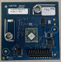
M7 is a radio station, supporting both UHF radio . Specifically developed for the
surveying and mapping as well as precision agriculture markets, it features long
communication distance, good protocol compatibility, and strong anti-interference
capability.
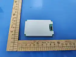
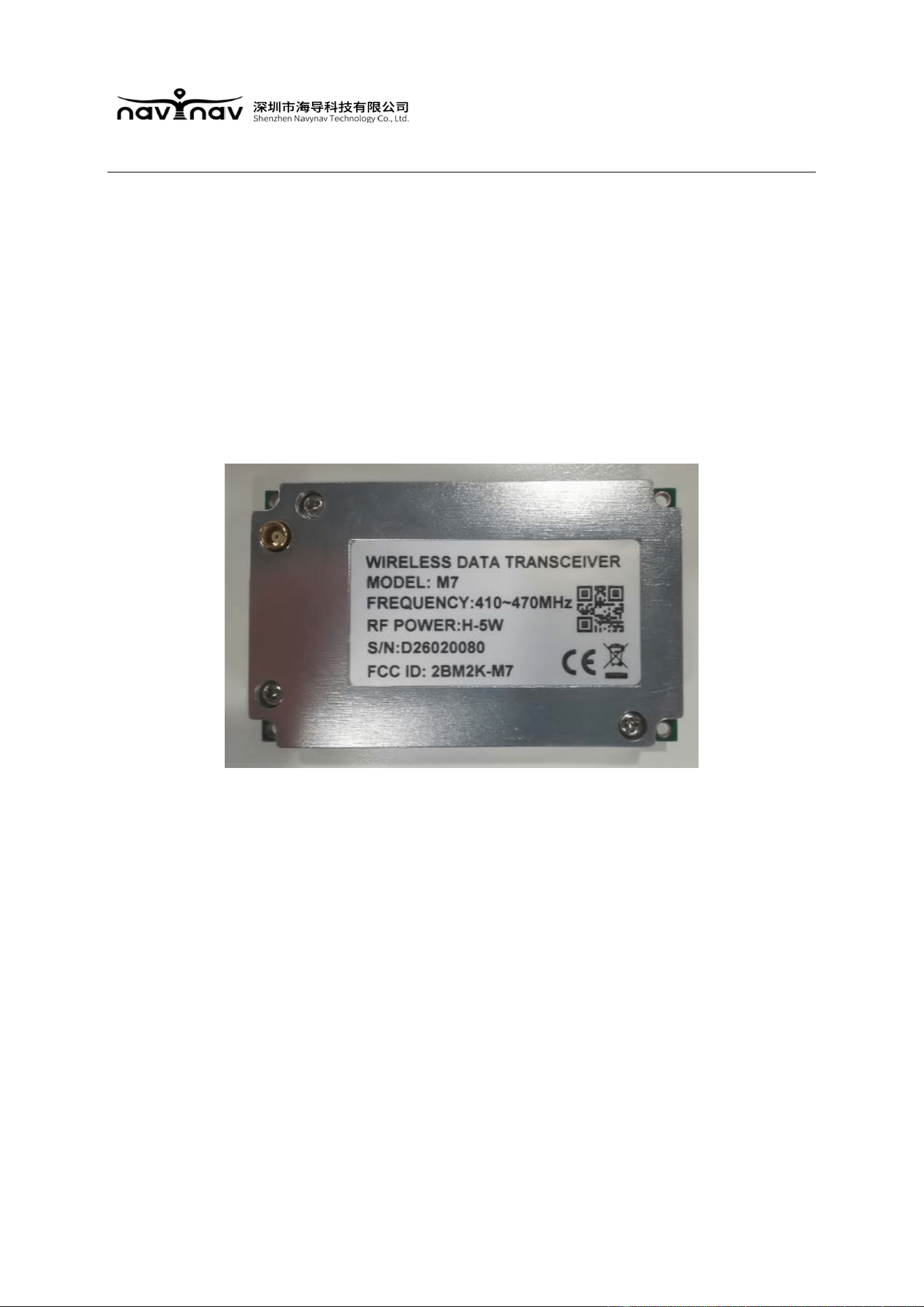
Figure 1-1: M7 appearance diagram
1.1 Product features
Radio station operating frequency range: 410-470 MHz
The package size and pin definition are compatible with HX-DU2005D and HX-DU5002D
radios.
The integration of transceivers can meet the requirements of communication links between
base stations and mobile stations.
Support online upgrade function.
Supports H, L power switching.
Document No. :
NQR.CP-M5-2401-001
2
1.2 Application field
Surveying and mapping, precision agriculture
II. Technical Specifications
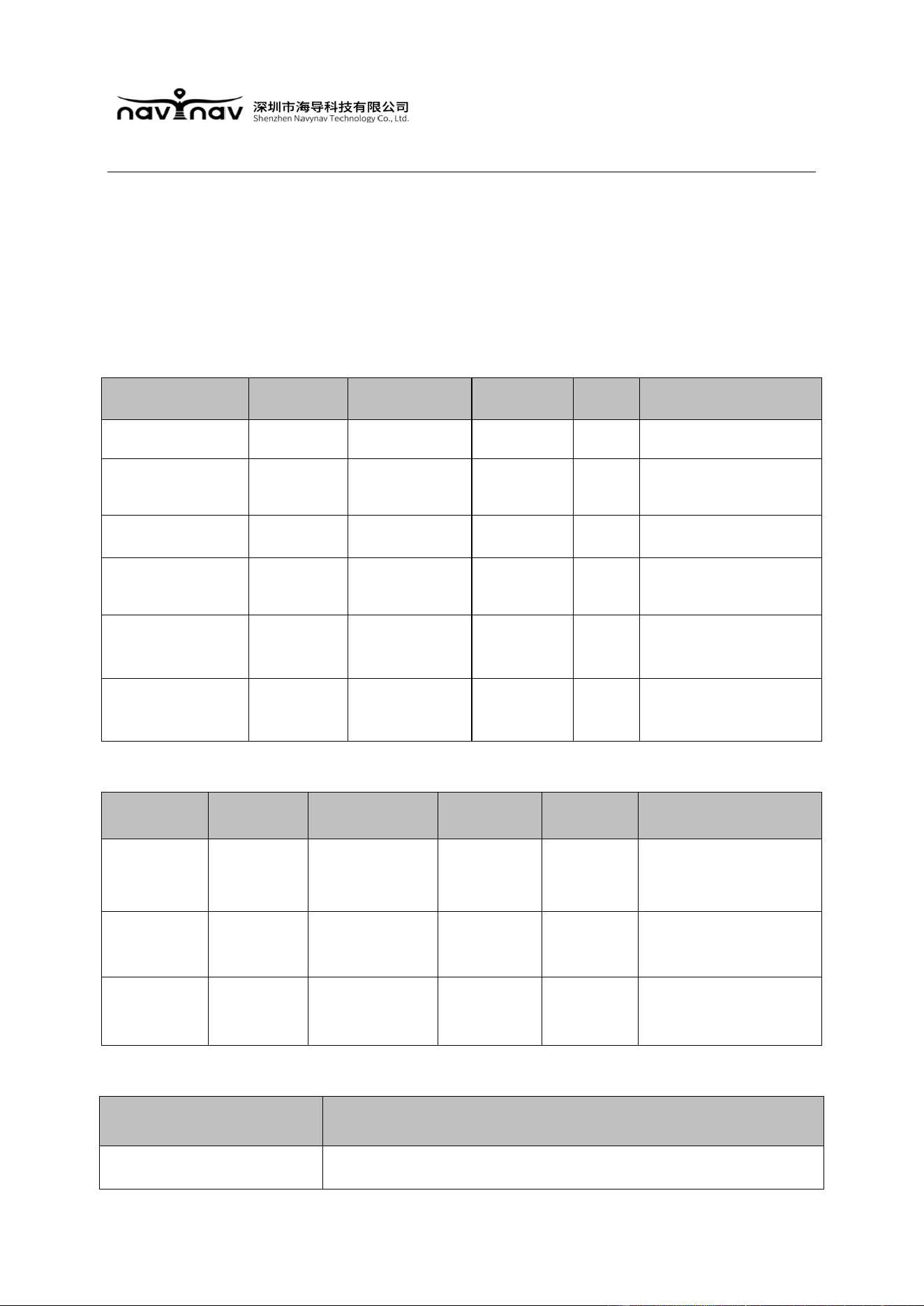
2.1 Working conditions
Parameter Minimum Typical value Maximum Unit Instructions
Working voltage \ 7.5 \ V
5W recommended @ 7.5V
Operating
temperature
-40 - 70 ℃
Operating humidity 10 - 90 %RH
Storage
temperature
-45 - 85 ℃
Electrostatic
discharge voltage
(Contact discharge)
- - 4 KV
Electrostatic
discharge voltage
(Air discharge)
- - 6 KV
2.2 Power consumption parameter
Parameter Minimum Typical value Maximum Unit Remarks
Emission
current
0.8 1.6 1.8 A
1W transmitting current 0.8A
2W transmitting current 1.1A
5W transmitting current 1.6A
Receive
current
- 80 - mA
Standby
current
- 80 - mA
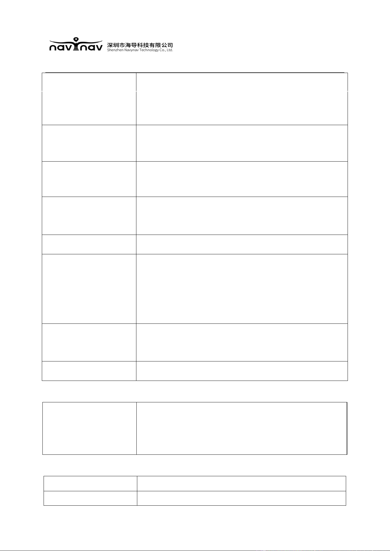
2.3 Radio frequency characteristics
Item Content
Operating frequency 410-470 MHz
Do
cument No. :
N
QR.CP-M5-2401-001
3
Working mode half-duplex
Channel bandwidth
12.5kHz
Modulation scheme
4FSK
FSK modes
Carrier power
5.0W, 2.0W, Three power levels are available
(default antenna port impedance is 50Ω)
Carrier power stability
±1.5 dB
Power consumption
(typical value)
Transmitting high power: [email protected] DC
Transmitting medium power: [email protected] DC
Standby power consumption: [email protected] DC
Reception sensitivity
FSK mode: better than -114dBm@BER 10-5,9600
Co-channel suppression >-12dB
2.
4 Modem
Serial port speed
9600bps, 19200bps, 38400bps, 115200bps
2.
5 Operating temperature
Operating temperature
-40~+75℃
Storage temperature
-45~+85℃
Document No. :
NQR.CP-M5-2401-001
4
2.
6 Communication interface
Item Content
Serial port
Standard TTL level
Data bit: 8 bits
Stop bit: 1 bit
Validation: No validation
2.
7 Structural characteristics
Item Content
Size
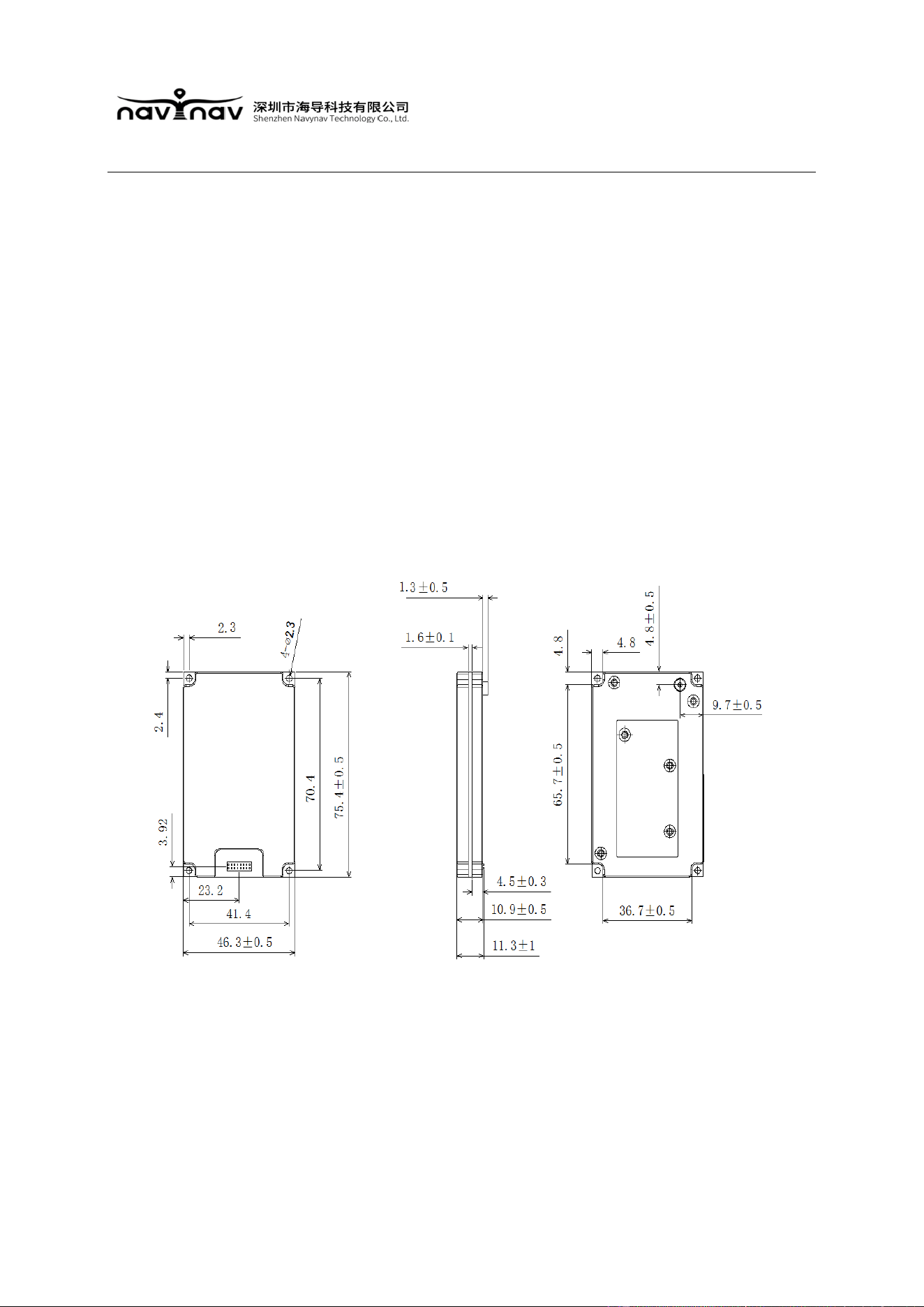
75 (length) × 46 (width) × 11 (height) mm
Weight
About 60g
Antenna interface
MCX female socket
Antenna interface
impedance
50 ohm
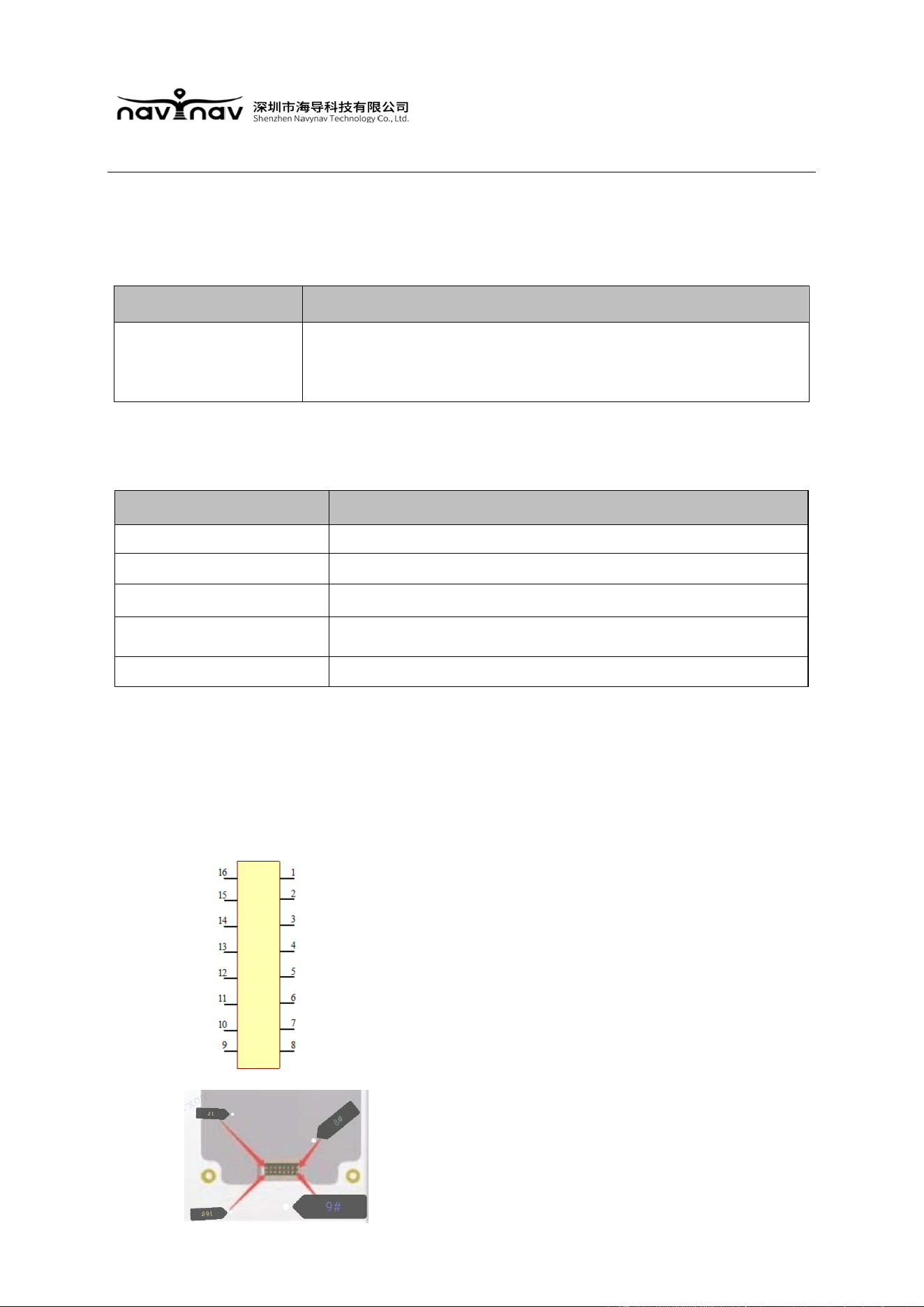
Data interface 2*8pin /1.27mm
III. Pin Definition
The distribution of M7 pins is shown in the figure below:
Pin definition:
Pin 1 - VCC - regulated +7.5V DC power input
Pin 2 - VCC - regulated +7.5V DC power input
Pin 3 - VCC - regulated +7.5V DC power input
Pin 4 - VCC - regulated +7.5V DC power input
Pin 5 - RSSI output
Pin 6 - suspended
Pin 7 - TXD
Pin 8 - RXD
Pin 9 - CONF IG - pull down to enter configuration
mode, High level indicates data transmission mode
Pin 10 - for testing, needs to be suspended
Pin 11 - for testing, needs to be suspended
Pin 12 - for testing, needs to be suspended
Pin 13 - External power supply negative input
Pin 14 - External power supply negative input
Pin 15 - External power supply negative input
Pin 16 - External power supply negative input
Document No. :
NQR.CP-M5-2401-001
5
IV. Mechanical characteristics
4.1 Module size
The view and dimensions are shown in the following figure

Document No. :
NQR.CP-M5-2401-001
6
Any Changes or modifications not expressly approved by the party responsible for
compliance could void the user's authority to operate the equipment.
This device complies with part 15 of the FCC Rules. Operation is subject to the following two
conditions: (1) This device may not cause harmful interference, and (2) this device must
accept any interference received, including interference that may cause undesired operation.
This equipment has been tested and found to comply with the limits for a Class B digital
device, pursuant to part 15 of the FCC Rules. These limits are designed to provide reasonable
protection against harmful interference in a residential installation. This equipment generates
uses and can radiate radio frequency energy and, if not installed and used in accordance with
the instructio
ns, may cause harmful interference to radio communications. However, there is
n
o guarantee that interference will not occur in a particular installation. If this equipment does
cause harmful interference to radio or television reception, which can be determined by
turning the equipment off and on, the user is encouraged to try to correct the interference by
one or more of
the following measures:
—Reorient or relocate the receiving antenna.
—In
crease the separation between the equipment and receiver.
—Connect the equipment into an outlet on a circuit different from that to which the receiver is
connected.
—Consult the dealer or an experienced radio/TV technician for help.
This equipment complies with FCC radiation exposure limits set forth for an uncontrolled
environment .This equipment should be installed and operated with minimum distance 50cm
between the radiator& your body.
Integration instructions for host product manufacturers according to KDB 996369 D03 OEM
Manual v01
2.2 List of applicable FCC rules
CFR 47 FCC PART 90 has been investigated. It is applicable to the modular.
2.3 Specific operational use conditions
This module is stand-alone modular. If the end product will involve the
Multiple simultaneously transmitting condition or different operational conditions for a
stand-alone
Document No. :
NQR.CP-M5-2401-001
7
modular transmitter in a host, host manufacturer have to consult with module
manufacturer for the installation method in end system.
2.4 Limited module procedures
Not applicable
2.
5 Trace antenna designs
Not applicable
2.6 RF exposure considerations
This equipment complies with FCC radiation exposure limits set forth for an uncontrolled
environment .This equipment should be installed and operated with minimum distance 50cm
between the radiator& your body. If the device built into a host as a portable usage, the
additional RF exposure evaluation may be required as specified by 2.1093.
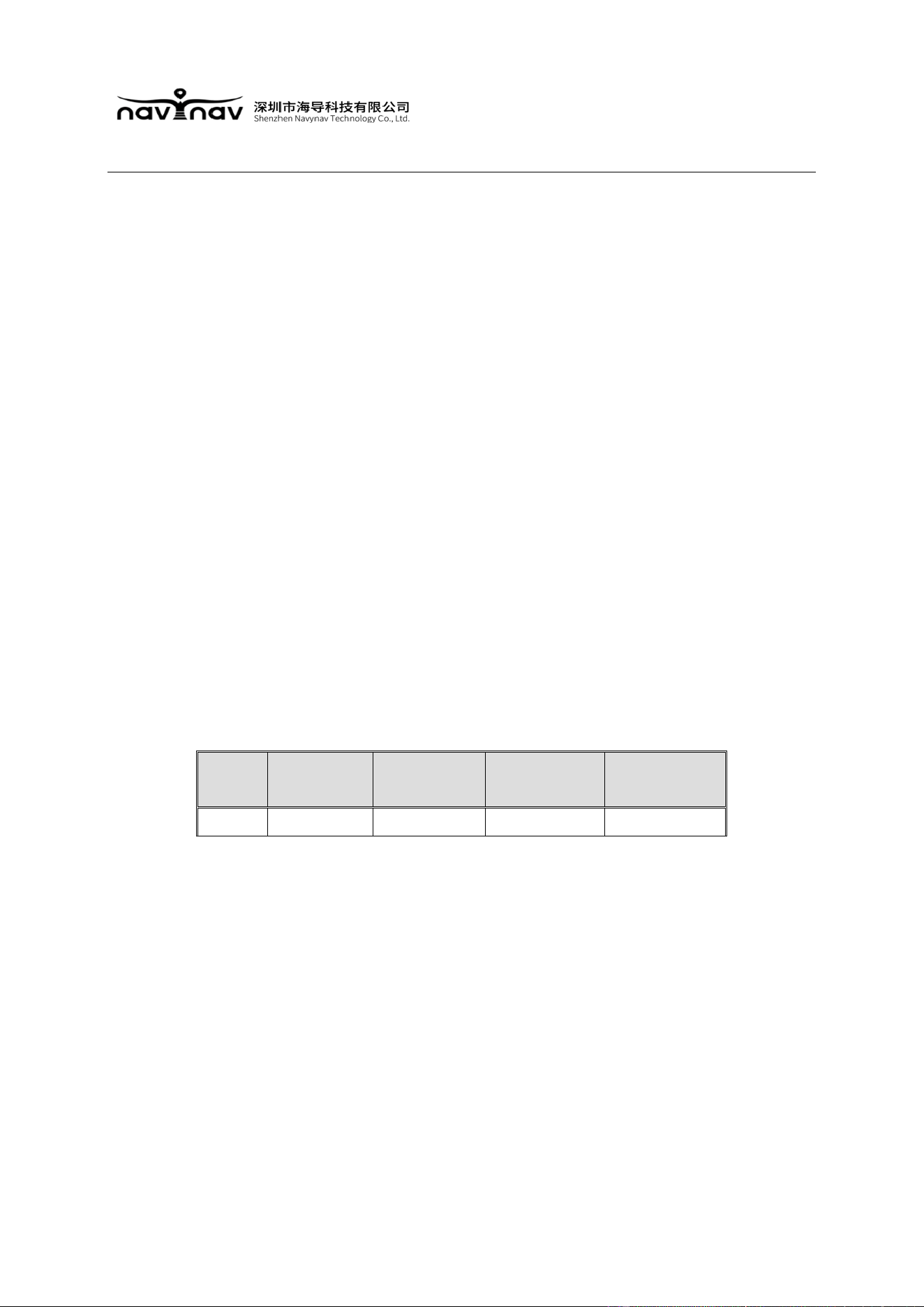
2.7 Antennas
This
radio transmitter FCC ID: 2BM2K-M7 has been approved by Federal
Communications Commission to operate with the antenna types listed below, with the
maximum permissible gain indicated. Antenna types not included in this list that have
a gain greater than the maximum gain indicated for any type listed are strictly prohibited
for use with this device.
No.
Antenna
Type
Antenna Gain Impedance
Frequency
Range
1 Dipole 2 dBi 50Ω 410-470MHz
2.8 Label and compliance information
The final end product must be labeled in a visible area with the following " Contains
FCC ID: 2BM2K-M7”
2.9 Information on test modes and additional testing requirements
Host manufacturer is strongly recommended to confirm compliance with FCC requirements
for the transmitter when the module is installed in the host.
2.10 Additional testing, Part 15 Subpart B disclaimer
Host manufacturer is responsible for compliance of the host system with module installed

Document No. :
NQR.CP-M5-2401-001
8
with all other applicable requirements for the system such as Part 15 B