SPECIFICATIONS
AC POWER SUPPLY REQUIREMENTS 120 V
MOTOR
100 W Permanent Magnet DC
DC POWER
12 V Battery
600005W-001 H 03/20
© 2020, WAYNE/Scott Fetzer Company
CONSTRUCTION
MOTOR HOUSING Coated Steel
MOTOR SHAFT Stainless Steel
IMPELLER Thermoplastic
VOLUTE Cast Iron
PUMP DISCHARGE 1-1/2 in. NPT
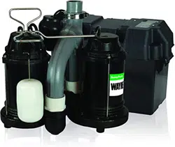
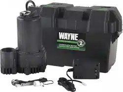
12 Volt Backup Sump Pump
Intended for Indoor Use Only
Please read and save these instructions. Read carefully before attempting to assemble, install,
operate or maintain the product described. Protect yourself and others by observing all safety
information. Failure to comply with instructions could result in personal injury and/or property
damage! Retain instructions for future reference.
Operating Instructions and Parts Manual ESP25n
www.waynepumps.com
PERFORMANCE GAL/HR
Model HP
Discharge Head (Lift Distance)
0 ft 5 ft 10 ft 15 ft
ESP25n 12 V 2700 2100 1500 660
* Battery not included. A Wayne WSB1275 75 Amp
Hour Battery is recommended.
Operating Instructions and Parts Manual
2
REMINDER: Keep your dated proof of purchase for warranty purposes! Attach it to this manual or file it for safekeeping.
GENERAL SAFETY INFORMATION
CALIFORNIA PROPOSITION 65
This product can expose you to chemicals, including DEHP,
which is known to the State of California to cause cancer,
birth defects and reproductive harm. For more information,
go to www.P65Warnings.ca.gov.
Ce produit peut vous exposer à des produits chimiques,
notamment du DOP, reconnus par l’État de Californie comme
étant cancérigènes et à l’origine d’anomalies congénitales
et de problèmes de l’appareil reproductif. Pour plus de
renseignements, visiter le site www.P65Warnings.ca.gov.
Do NOT use to pump flammable or explosive
fluids such as gasoline, fuel oil, kerosene, etc. Do not use in a
flammable and/or explosive atmosphere. Pump should only be used to
pump clear water. Fatal injury and/or property damage could result and
void warranty.
Ne PAS utiliser pour pomper des
fluides inflammables ou explosifs tels que l'essence,
le mazout, le kérosène, etc. Ne pas utiliser dans un
environnement inflammable et/ou explosif. La pompe ne doit être
utilisée que pour pomper de l'eau claire. Des blessures corporelles et/
ou des dégâts matériels pourraient en résulter et annuler la garantie.
if the basement has water or moisture on the
floor, do not walk on wet area until all power is turned off. If the shutoff
box is in the basement, call an electrician. Remove pump and either
repair or replace. Failure to follow this warning could result in fatal
electric shock.
Si le sous-sol a de l'eau ou
de l'humidité sur le plancher, ne pas marcher aux
endroits mouillés avant que le courant ne soit coupé. Si
la boîte d'arrêt est au sous-sol, appeler un électricien.
Enlever la pompe et la réparer ou la remplacer. Le non-respect de cet
avertissement pourrait entraîner un choc électrique fatal.
DESCRIPTION
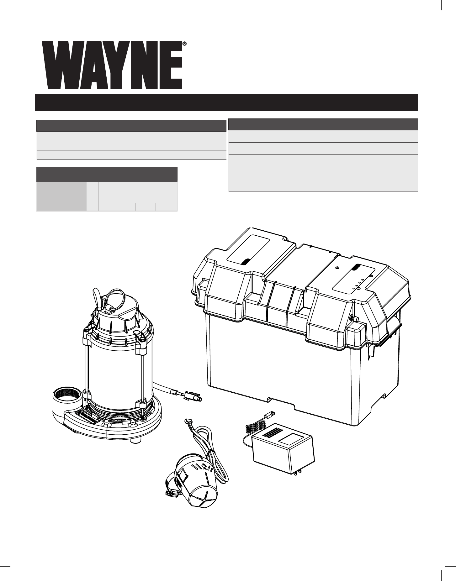
The ESP25n is a battery operated backup sump pump. It does
not replace a regular pump. It is designed to provide protection in
the event household electrical power fails. This system is intended
for indoor use only. This pump is intended for use with one 12 V
battery.
Installation of this pump outdoors, unprotected from the
weather, may cause hazardous conditions and will void
warranty. If using outdoors, protect pump from direct weather
elements such as sun, rain, sleet, snow, and extreme
temperature changes. Water inside the pump may freeze,
limiting its performance and damaging the pump and pipes.
UNPACKING
Inspect this unit before it is used. Occasionally, products are
damaged during shipment. If the pump or components are
damaged, return the unit to the place of purchase for replacement.
Call Customer Support (800-237-0987).
SAFETY SIGNAL WORDS
This manual contains information that is very important to know
and understand. This information is provided for SAFETY and
to PREVENT EQUIPMENT PROBLEMS. To help recognize this
information, observe the following symbols.
Danger indicates an imminently hazardous
situation which, if NOT avoided, WILL result in death or serious injury.
La mention Danger indique une situation
dangereuse imminente qui, si elle n’est pas évitée, ENTRAÎNE la mort ou
des blessures graves.
Warning indicates a potentially hazardous
situation which, if NOT avoided, COULD result in death or serious injury.
La mention avertissement indique une
situation potentiellement dangereuse qui, si elle n’est pas évitée, risque
d’entraîner des lésions corporelles graves ou même la mort.
Caution indicates a potentially hazardous
situation which, if NOT avoided, MAY result in minor or moderate injury.
MISE EN GARDE
La mention mise en garde indique une
situation potentiellement dangereuse qui, si elle n’est pas évitée,
pourrait entraîner des blessures mineures ou modérées.
Notice indicates important information, that if
NOT followed, MAY cause damage to equipment.
Operating Instructions and Parts Manual
3
ESP25n
All wiring must be performed by a qualified
electrician.
L'ensemble du câblage doit être effectué par un
électricien qualifié.
Do not expose battery to sparks or flame as an
explosion or fire could result.
Ne pas exposer la batterie à des étincelles ou
des flammes. Une explosion ou un incendie pourrait en résulter.
Battery acid is corrosive. Avoid spilling on skin
or clothing. Eye protection must be worn when handling the battery.
L'acide de la batterie est corrosif. Évitez
les éclaboussures sur la peau ou les vêtements. Toujours porter une
protection oculaire pour manipuler la batterie.
check valve must be used on both the primary
and backup sump pump discharge.
Un clapet de non-retour doit être utilisé sur le
tuyau de décharge du puisard principal et de secours.
A ground fault circuit interrupt er (gfci) is
required.
Un disjoncteur de fuite à la terre doit être
installé.
BATTERY INFORMATION
The system is designed to operate most efficiently with AGM bat-
teries. AGM batteries cost slightly more, but they can last longer.
The oversize battery case (included) will accommodate a 12 Volt
AGM battery (up to a group 27-frame size).
NOTE: Batteries not to be wired parallel
Be certain that the area around the batteries
is well ventilated. Before servicing the batteries, blow away gasses by
waving a piece of cardboard near the battery.
S'assurer que la zone autour des batteries est
bien ventilée. Avant d’effectuer l’entretien des batteries, évacuer les gaz
en agitant un morceau de carton près des batteries.
Dangerous hydrogen gas can be released from
the batteries while charging. Sparks can ignite the gas in an enclosed
space. Wear safetly goggles when connecting batteries. Battery
connections should be made in a well ventilated area.
De l’hydrogène dangereux peut s’échapper des
batteries pendant le chargement. Les étincelles peuvent enflammer le
gaz dans un espace clos. Porter des lunettes de sécurité pour brancher
les batteries. Les connexions de la batterie doivent être effectuées dans
un endroit bien ventilé.
Working in the vicinity of lead acid batteries
can be dangerous. Before making the connections or servicing the
batteries, read and follow instructions on all applicable instruction
manuals. To reduce the risk of battery explosion, follow the instructions
in this manual and those published by the battery manufacturer, as well
as those of any other equipment used in the surrounding area.
Travailler à proximité de batteries au plomb-
acide peut être dangereux. Avant d'effectuer une connexion ou
d'effectuer l'entretien des batteries, lire et suivre les instructions de
tous les manuels d'instructions applicables. Afin de réduire le risque
d’explosion de la batterie, suivre les instructions de ce manuel, celles
publiées par le fabricant de la batterie, ainsi que celles de tout autre
équipement utilisé à proximité.
An assistant should be present or close enough
to come to your aid in the event of an emergency. Have a reliable source
of fresh water and soap nearby in case batttery acid contacts skin or
eyes.
Wear eye or clothing protection when working
around lead acid batteries. Avoid touching your eyes when working
around lead acid batteries.
if battery acid contacts your eye(s), flush
with cold running water for 10 minutes and seek immediate medical
attention. If acid contacts your skin or clothing, wash immediately with
soap and water.
Si de l’acide de batterie entre en contact avec
les yeux, les rincer avec de l’eau courante froide pendant 10 minutes et
consulter immédiatement un médecin. Si l’acide entre en contact avec
la peau ou les vêtements, les laver immédiatement avec de l’eau et du
savon.
Never smoke or allow a spark or flame in the
vicinity of the battery.
Ne jamais fumer ou laisser une étincelle ou une
flamme près de la batterie.
Operating Instructions and Parts Manual
4
Avoid dropping metal tools on the battery posts
because they may spark or short-circuit the system or battery, causing
an explosion.
Éviter de faire tomber des objets en métal
sur les bornes de la batterie: cela pourrait créer des étincelles ou des
courts-circuits du système ou de la batterie, provoquant une explosion.
Installation may take several hours. Have
appropriate means of removing water while sump pumps are disabled.
INSTALLATION
1. Turn power to main pump off.
2. Pump must be installed using 1-¼ in. or 1-1/2 in. rigid PVC
piping.
The backup pump can be installed with a separate dedicated dis-
charge line (Method 1), or tied into an existing sump pump line with
a check valve (Method 2).
Unplug the existing AC pump. Failure to follow
this warning could result in fatal electric shock.
Débrancher la pompe c.A. Ne pas respecter cet
avertissement pourrait entraîner un choc électrique mortel.
1. Verify that the existing AC pump is in good working order. If the
AC pump is questionable, it is typically recommended that the
unit be replaced with a 1/3 HP or 1/2 HP pump.
2. Remove any silt or accumulated debris from the sump pit and
surrounding area.
METHOD 1 (PREFERRED)
1. Locate the backup pump on a solid, level surface in the sump
pit. Do not place the pump on a loose or sandy surface. Small
stones or sand may damage the pump resulting in potential
pump failure.
2. This pump has a 1-1/2 in. NPT discharge. If a 1-1/4 in. dis
charge pipe is desired, an adapter (not included) will be
necessary. Smaller diameter piping will reduce pump flow, rate
and performance.
3. Cut a 4 ft. section of 1-1/2 in. or 1-1/4 in. diameter rigid PVC
pipe. Cement pipe to a threaded fitting. Cement pipe into pipe
coupling. Attach pipe section to the backup pump discharge
adapter.
4. Screw on to pump discharge.
Be careful NOT to strip or cross thread plastic
fittings or check valves. Flex hose is prohibited. Rigid PVC or metal pipe
is required for permanent installation.
5. Place the pump with the 4 ft. section of PVC pipe on a solid,
level surface in the sump pit on an elevated surface.
6. Attach the required rubber check valve (sold separately) to the
top of the discharge pipe. This will allow the pump or check valve
to be removed easily for servicing.
NOTE: Check valves can be placed directly in the pump discharge
if desired. However, for ease of disassembly, it is recommended
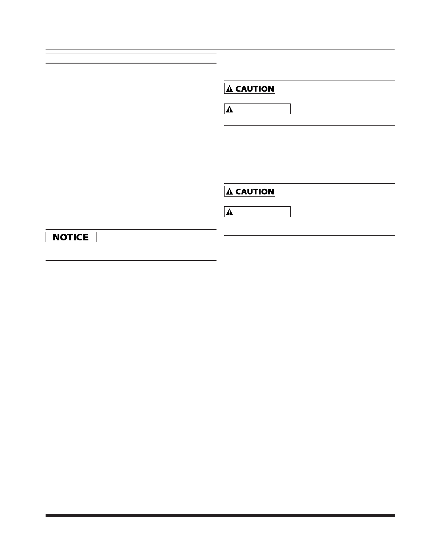
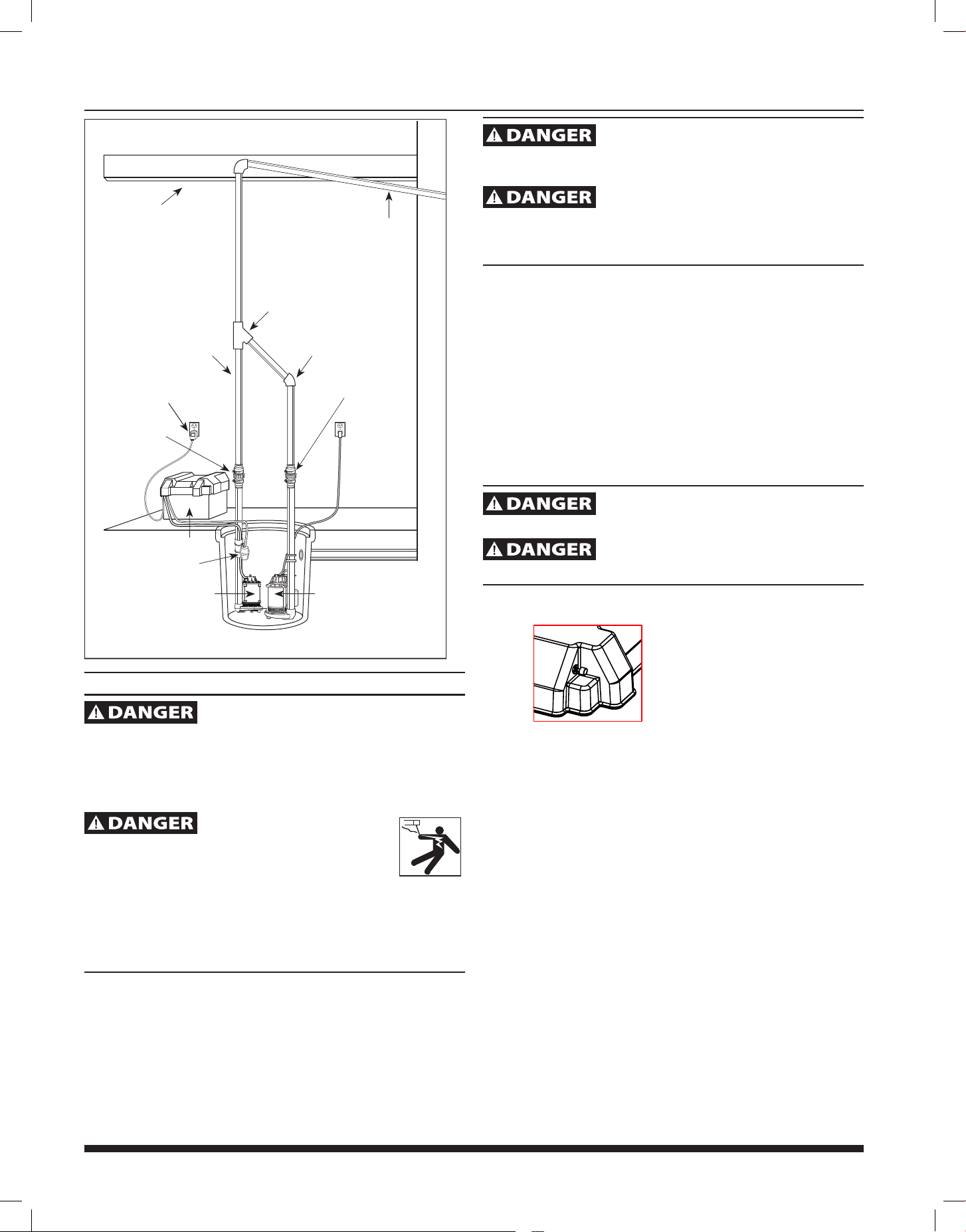
that check valves be placed above the sump as shown in Figure 1.
The remainder of the discharge pipe installation will vary depend-
ing on individual circumstances. Using sound plumbing practices,
route the discharge pipe to an exterior wall by the shortest path.
Keep turns to a minimum because they reduce flow output of the
pump. The pipe that exits the building structure should be sloped
downward so that water will not freeze in the pipe.
When installing the separate discharge pipe, drill through the
outside wall with appropriate drilling equipment. Seal the hole to
prevent water from entering.
FLOOR JOIST
RIGID
PVC
PIPE
TRANSFORMER
REQUIRED
CHECK VALVE
(SEE STEP 6)
BATTERY BOX
BACKUP DC
PUMP
PRIMARY AC
PUMP
SLOPE
PIPE
DOWN
REQUIRED
CHECK VALVE
(SEE STEP 6)
1 1/4 IN.
OR 1 1/2
IN.
PVC PIPE
FLOAT SWITCH
Figure 1- Method 1
Operating Instructions and Parts Manual
5
ESP25n
INSTALLATION CONT'D
Method 2
If a separate, dedicated discharge is not possible as in Method
1, the backup pump can be tied into the AC operated pump's
discharge pipe by installing a "Y" connector. Two check valves will
be required.
1. Locate the backup pump on a solid, level surface in
the sump pit. Do not place the pump on a loose or
sandy surface. Small stones or sand may damage the
pump resulting on potential pump failure.
2. This pump has a 1-1/2 in. NPT discharge. If a 1-1/4 in.
discharge pipe is desired, an adapter (not included) will
be necessary. Smaller piping will reduce pump flow,
rate and performance.
3. A check valve is required in the discharge line
of BOTH the Main AC pump and the backup pump to
prevent recirculation of water into the sump pit.
4. Cut a 4 ft. section of 1-1/2 in. or 1-1/4 in. diameter rigid PVC
pipe. Cement pipe to a threaded fitting. Cement pipe into pipe
coupling. Attach pipe section to the back-up pump discharge
adapter.
5. Screw on to pump discharge.
Be careful NOT to strip or cross thread plastic
fittings or check valves. Flex hose is prohibited. Rigid PVC or metal pipe
is required for permanent installation.
6. Place the pump with the 4 ft. section of PVC pipe on the
sump floor or on an elevated surface if required.
7. Attach the required rubber check valve (sold separately) to the
top of the discharge pipe. This will allow the pump or check
valve to be removed easily for servicing.
8. Duplicate the discharge piping arrangement for the
primary AC pump if the discharge line has to be
adjusted to accomodate a second pump.
9. Glue a 45º elbow to the short pipe on the back-up
pump. Glue a "Y" adapter to the short pipe on the
existing pump, as shown in illustration for Method 2.
10. Glue a short piece of PVC pipe between the 45º elbow
and the "Y".
NOTE: Check valves can be placed directly in the pump
discharge if desired. However, for ease of disassembly, it is
recommended that check valves be placed above the sump as
shown in Figure 2.
The remainder of the discharge pipe installation will vary depending
on individual circumstances. Using sound plumbing practices, route
the discharge pipe to an exterior wall by the shortest distance.
Methods 1 and 2
Install float switch at least 10 in.-12 in. above bottom of sump pit
so that backup unit turns on only when the water level is higher
than the normal "on" level for main pump. Use the hose clamp
provided to secure the switch to the discharge pipe. Make sure
power wires do not interfere with float switch, pump inlet, or main
pump operation. Backup pump must not be allowed to run dry.
Control Box Installation
1. Place battery in box, attach red cable to positive battery
post and black cable to negative battery post.
if cables are reversed, damage to the control box
or battery will result, and void warranty .
MISE EN GARDE
Si les câbles sont inversés, la boîte de
contrôle ou la batterie pourrait être endommagée et la garantie annulée.
2. Plug the float switch, pump and transformer into the
appropriate connectors. The connections are all unique and
cannot be interchanged.
3. Put lid on box, and place the battery within six feet of the
sump and a 115 VAC separately fused outlet. The outlet
must be protected by a ground fault circuit interrupter (GFCI).
The area must also be clean, dry and well ventilated.
Do not allow battery box to get wet, or expose it
to moisture. Electronics will be damaged and void warranty.
MISE EN GARDE
Ne pas laisser le coffre de la batterie être
mouillé ou exposé à l’humidité. Les appareils électroniques seront
endommagés et la garantie sera annulée.
4. Test pump operation by filling the sump with water while the
main pump is unplugged. If the pump operates properly, plug
the transformer into the GFCI protected outlet to begin charg
ing the battery.
5. Protect electrical cord from sharp objects, hot surfaces, oil and
chemicals. Avoid kinking the cord. DO NOT USE PUMP WITH
DAMAGED CORD.
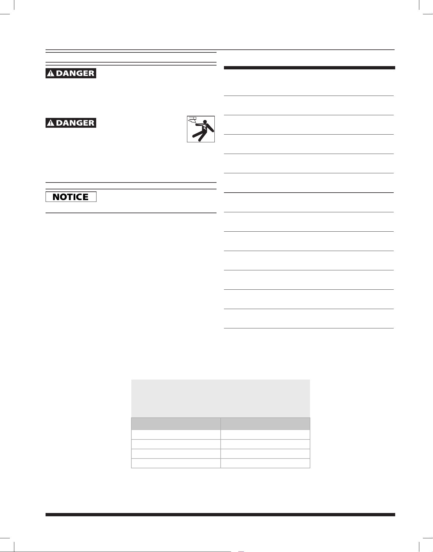
Operating Instructions and Parts Manual
6
OPERATION
Always disconnect the power source before
attempting to install, service, relocate or maintain the pump. Never
touch sump pump motor, water or discharge piping when pump is
connected to electrical power. Never handle a pump or pump motor
with wet hands or when standing on wet or damp surface or in water.
Fatal electric shock could occur.
Toujours débrancher le cordon
d'alimentation avant d'essayer d'installer, de réparer, de
déplacer ou de faire l'entretien de la pompe. Ne jamais
toucher le moteur de la pompe de puisard, l'eau ou les
tuyaux d'évacuation lorsque la pompe est branchée à une source
d'alimentation électrique. Ne jamais manipuler une pompe ou le moteur
d’une pompe avec les mains humides, ou debout sur une surface
mouillée ou humide ou dans l’eau. Cela pourrait occasionner un choc
électrique.
Risk of electrical shock! Use a GFCI receptacle
to reduce the risk of fatal electric shock. Cutting the cord will void the
warranty and make the pump inoperable.
Risque de choc électrique! Utiliser une prise
avec disjoncteur de fuite à la terre pour réduire le risque de choc
électrique. Couper le cordon annulera la garantie et rendra la pompe
inutilisable.
1. After installation, the backup pump will start when
the water level rises above the backup float switch.
2. The control box has a DC charger designed to shorten the
recharging time of your battery, and to prevent overcharging.
In addition, the control box has a time delay which keeps the
pump from repeated, short cycles when it shuts off. The time
delay feature will allow the pump to run 20-25 seconds after the
switch reaches the off position.
3. The control box contains multi-colored indicator lights. When
AC power is present, the lights will indicate the charging state,
and not reflect actual battery voltage, particularly with a defec-
tive battery. In order for the indicator light to provide an accu
rate reading, steps "a" through "d" must be followed.
Unplug main ac pump and the transformer. Risk
of electrical shock!
Débrancher la pompe principale et le
transformateur de courant c.A. Risque de choc électrique!
a. After main pump and transformer are unplugged, a power off
alert tone will sound for 30 seconds.
b. Press and release the self test button to activate the backup
pump.
c. When the pump stops, read the charge indicator lights:
Green: Indicates the battery is fully charged.
Yellow: Indicates battery is partially charged, but still operable.
Red: Battery is completely discharged or defective.
Red blinking: Battery discharged below level where pumping
can occur. Motor is locked out by controller until battery is
suficiently charged to run pump.
d. Plug in transformer and main AC pump. When main AC power
is out, and when pump has been running, the lights will indi-
cate battery status.
4. A chirping sound from the control box will accompany the red
light, indicating that the battery may require attention or
replacement. Voltage is only an indicator of battery condition
and may not reflect the true condition of the battery. See
maintenance for instruction on assessing battery condition.
5. A single thirty (30) second tone will sound when power to
the system is interrupted and the bottom power failure light
will illuminate. The unit will reset and the light will go out
automatically when power is restored.
6. A three (3) second tone will sound every time the pump starts.
FLOOR JOIST
RIGID
PVC
PIPE
TRANSFORMER
REQUIRED
CHECK VALVE
(SEE STEP 3 & 7)
BATTERY BOX
PRIMARY AC PUMPBACKUP DC PUMP
SLOPE
PIPE
DOWN
REQUIRED
CHECK VALVE
(SEE STEP 3)
Figure 2 - Method 2
"Y"
CONNECTOR
45º ELBOW
FLOAT SWITCH
Operating Instructions and Parts Manual
7
ESP25n
MAINTENANCE
Always disconnect the electrical supply before
attempting to install, service or relocate or perform any maintenance. If
the power source is out of sight, lock and tag in the open (off) position
to prevent unexpected power application. Failure to do so could result
in fatal electric shock. Only qualified electricians should repair this unit.
Improper repair could result in fatal electric shock.
Toujours couper le courant
avant d'essayer d'installer, de réparer, de déplacer ou de
procéder à l'entretien. Si la source d'alimentation est hors
de vue, verrouiller et étiqueter en position ouverte (off)
pour éviter tout rétablissement de l'électricité inattendu. Le non-respect
de ces instructions pourrait entraîner un choc électric mortel. Seuls
des électriciens qualitifés devraient réparer cet appareil. Une mauvaise
réparation pourrait entraîner un choc électrique mortel.
Once a month, check the battery condition. To
check battery condition follow steps listed below:
1. Unplug the transformer.
2. Inspect the terminals and clamps for corrosion and tightness.
Clean and tighten as required.
3. Unplug the main pump and fill sump with water until backup
pump turns on. Repeat process two times to make sure pump
is operating normally.
4. If pump operates normally, plug transformer into GFCI wall
outlet, turn on main pump. If pump fails to operate normally,
see Troubleshooting guide and correct problem.
NOTES
Thank you for making Wayne Water Systems a key part of your
home maintenance program. If properly installed, maintained
and operated in accordance with Wayne Water Systems’ written
instructions, your pump should provide you with approximately
( * ) years of service.
Product Warranty ( * ) Expected Life
1 3
2 3
3 6
5 6

Operating Instructions and Parts Manual
8
LIMITED WARRANTY
For two years for ESP25n model from the date of purchase, from an authorized dealer, Wayne Water Systems will repair or replace, at its option for the original
purchaser, any part or parts of its Sump Pumps or Water Pumps (“Product”) found upon examination by Wayne Water Systems to be defective in materials or
workmanship. Please call Wayne Water Systems (800-237-0987) for instructions. Be prepared to provide the model number and the serial number when exercising this
warranty. All transportation charges on Products or parts submitted for repair or replacement must be paid by purchaser. This Limited Warranty is not transferrable.
This Limited Warranty does not cover Products which have been damaged as a result of accident, abuse, misuse, neglect, improper installation, improper maintenance,
or failure to operate in accordance with WAYNE’s written instructions.
This Limited Warranty does not cover Products which have been damaged as a result of accident, abuse, misuse, neglect, improper installation, improper maintenance,
or failure to operate in accordance with Wayne Water Systems’ written instructions.
THERE IS NO OTHER EXPRESS WARRANTY. IMPLIED WARRANTIES, INCLUDING THOSE OF MERCHANTABILITY AND FITNESS FOR A PARTICULAR PURPOSE, ARE
LIMITED TO ONE YEAR FROM THE DATE OF PURCHASE. THIS IS THE EXCLUSIVE REMEDY AND ANY LIABILITY FOR ANY AND ALL INDIRECT OR CONSEQUENTIAL
DAMAGES OR EXPENSES WHATSOEVER IS EXCLUDED.
In no event, whether as a result of breach of contract warranty, tort (including negligence) or otherwise, shall Wayne Water Systems or its suppliers be liable for any
special, consequential, incidental or penal damages.
You MUST retain your purchase receipt along with this form. In the event you need to exercise a warranty claim, you MUST send a copy of the purchase receipt along
with the material or correspondence. Please call Wayne Water Systems (800-237-0987) for return authorization and instructions.
DO NOT MAIL THIS FORM TO Wayne Water Systems. Use this form only to maintain your records.
MODEL NO._____________________ SERIAL NO._________________________ INSTALLATION DATE __________________________
ATTACH YOUR RECEIPT HERE
TROUBLESHOOTING CHART
Symptoms Possible Cause(s) Suggested Remedies
Pump will not
start or run
1. Connections not secure
2. Low or defective battery
3. Float switch stuck
4. Defective or blown fuse
5. Battery voltage below threshold, motor
locked out
1. Check all connections
2. Check battery and replace if low or defective
3. Make sure nothing is interfering with operation of switch
4. Pull the transformer from the wall outlet and remove. Check internal
fuse located inside the control box. If the fuse is blown, replace it with a
20 amp automotive type fuse
5. Wait for battery to recharge or replace with fresh battery
Motor hums but
will not run
1. Defective battery 1. Check battery and replace if low or defective
Pump runs but
pumps very little or
no water
1. Check valve missing or improperly
installed
2. Obstruction in discharge pipe
3. Discharge length and/or height exceeds
capacity of pump
4. Low or defective battery
1. Check to make sure check valves are installed between primary pump
discharge and backup sump pump are functioning properly
2. Check for obstruction and clear if necessary
3. If discharge is too high, a seperate line may be required with a lower
discharge height
4. Check battery and replace if needed
Pump cycles to
frequently
1. Check valve problem 1. Make sure check valves are installed correctly between primary pump
discharge and backup sump pump. Verify they are functioning properly
Power failure light
is on but A/C
power is available
1. Transformer is bad
2. Bad or no connection
3. Branch circuit breaker/fuse blown
1. Replace transformer
2. Check that A/C plug and transformer connections under lid are secure
3. Reset breaker or replace fuse
Operating Instructions and Parts Manual
9
ESP25n
For Replacement Parts or Customer Support, Call 1-800-237-0987
Please provide following information: Address any correspondence to:
- Model number Wayne Water Systems
- Serial number (if any) 101 Production Drive
- Part description and number as shown in parts list Harrison, OH 45030 U.S.A.
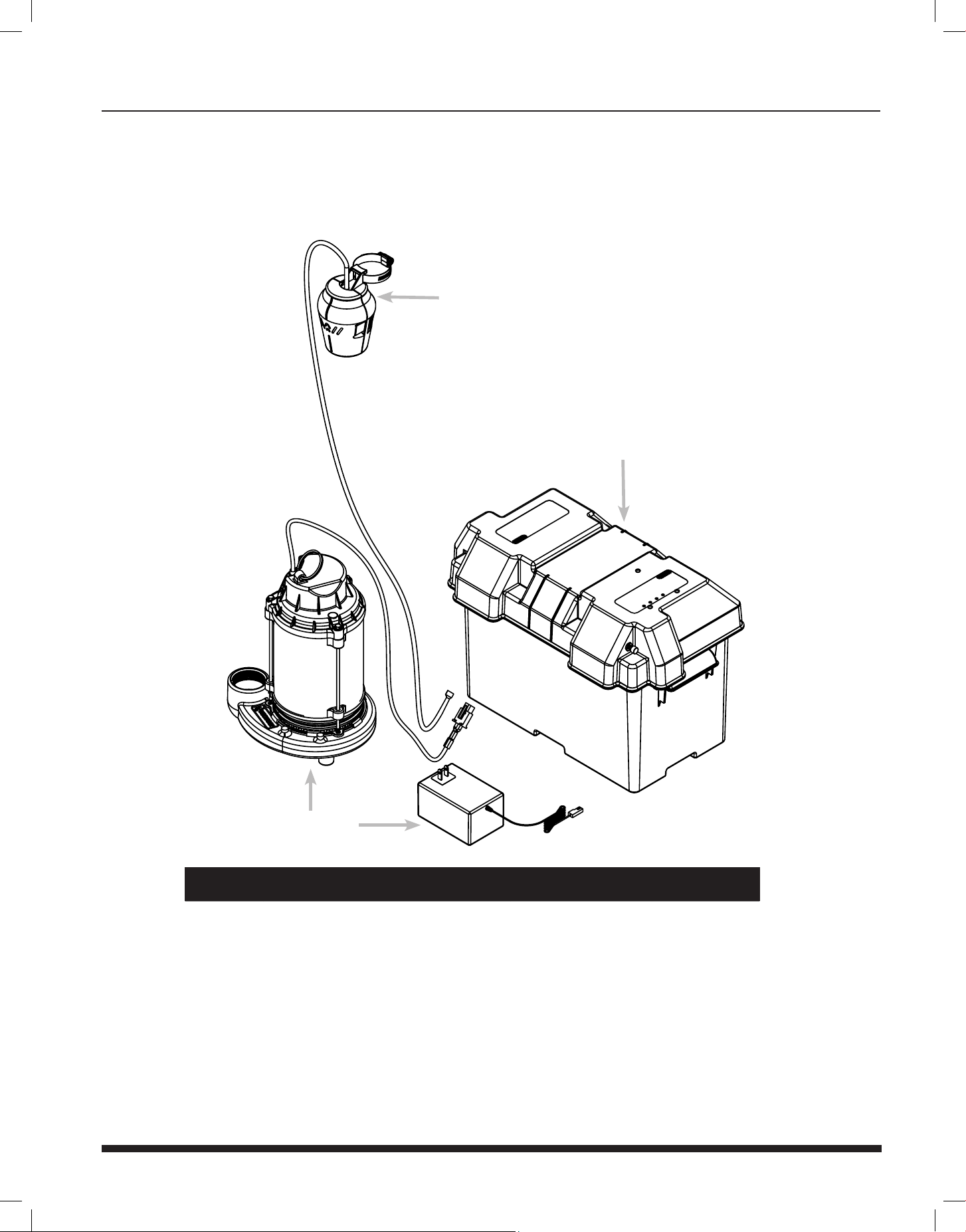
Reference
Number Description Part Number Quantity
1 Transformer 30221-001 1
2 Pump 58368-001 1
3 Lid Assembly 60184-WYN1 1
4 Floa Switch Assembly 60158-001
1
4
2
1
3

10
NOTES

11
ESP25n
NOTES

12