
Technical Support and E-Warranty Certificate
www.vevor.com/support
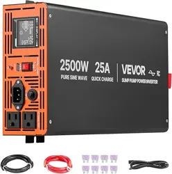
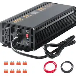
SUMP PUMP POWER INVERTER
OPERATION MANUAL
MODEL:SGPC2000W-121/SGPC2500W-121
We continue to be committed to provide you tools with competitive price.
"Save Half", "Half Price" or any other similar expressions used by us only represents an
estimate of savings you might benefit from buying certain tools with us compared to the major
top brands and does not necessarily mean to cover all categories of tools offered by us. You
are kindly reminded to verify carefully when you are placing an order with us if you are
actually saving half in comparison with the top major brands.


- 1 -
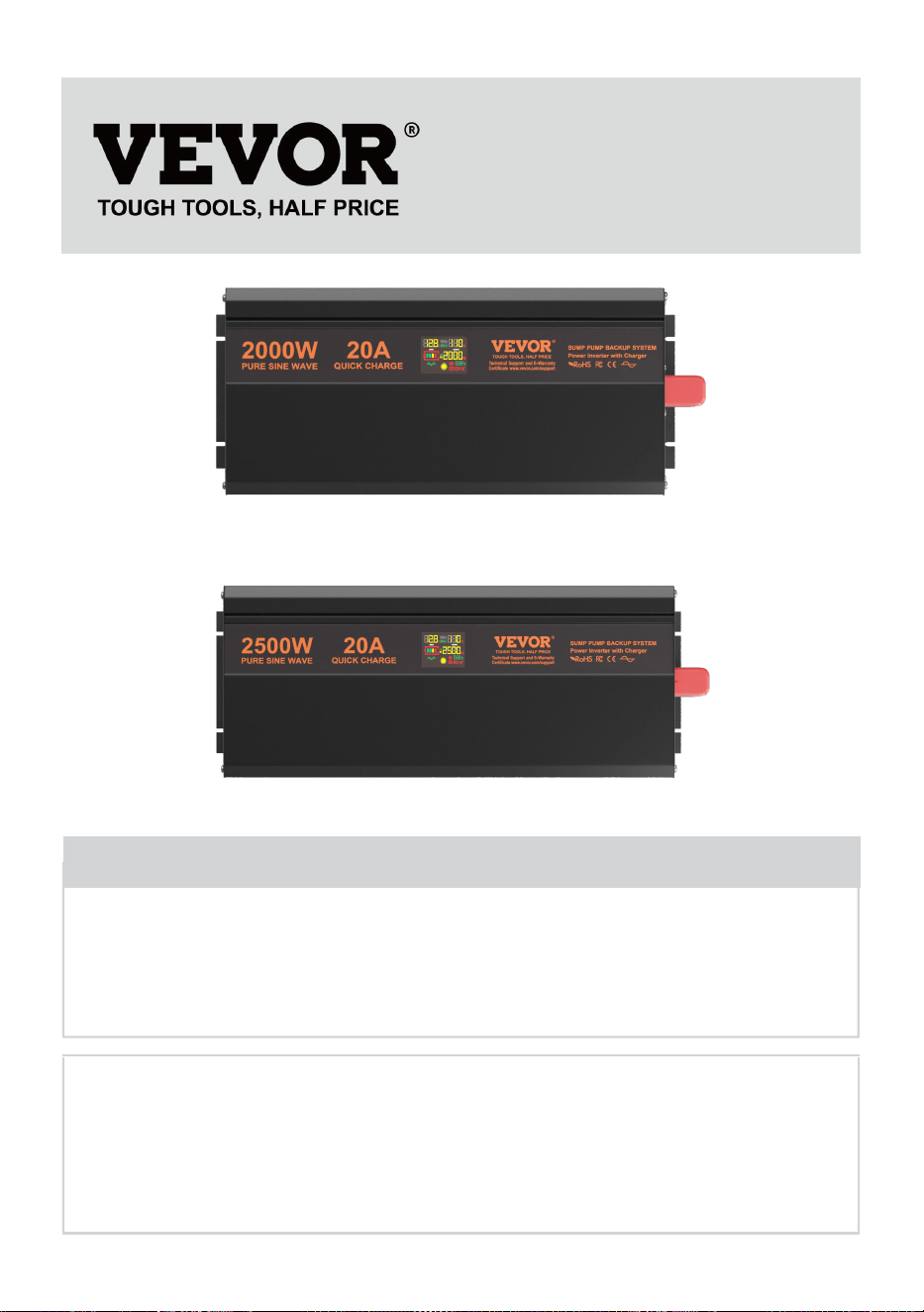
SGPC2000W-121
SGPC2500W-121
Have product questions? Need technical support? Please feel free to
contact us:
Technical Support and E-Warranty Certificate
www.vevor.com/support
NEED HELP? CONTACT US!
This is the original instruction, please read all manual instructions
carefully before operating. VEVOR reserves a clear interpretation of our
user manual. The appearance of the product shall be subject to the
product you received. Please forgive us that we won't inform you again if
there are any technology or software updates on our product.
SUMP PUMP POWER INVERTER
- 2 -
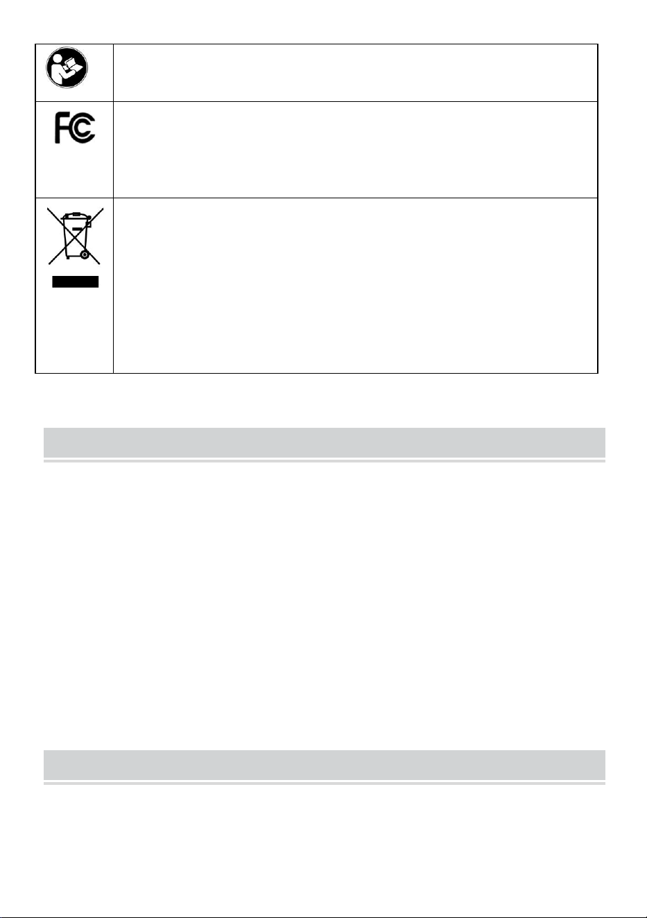
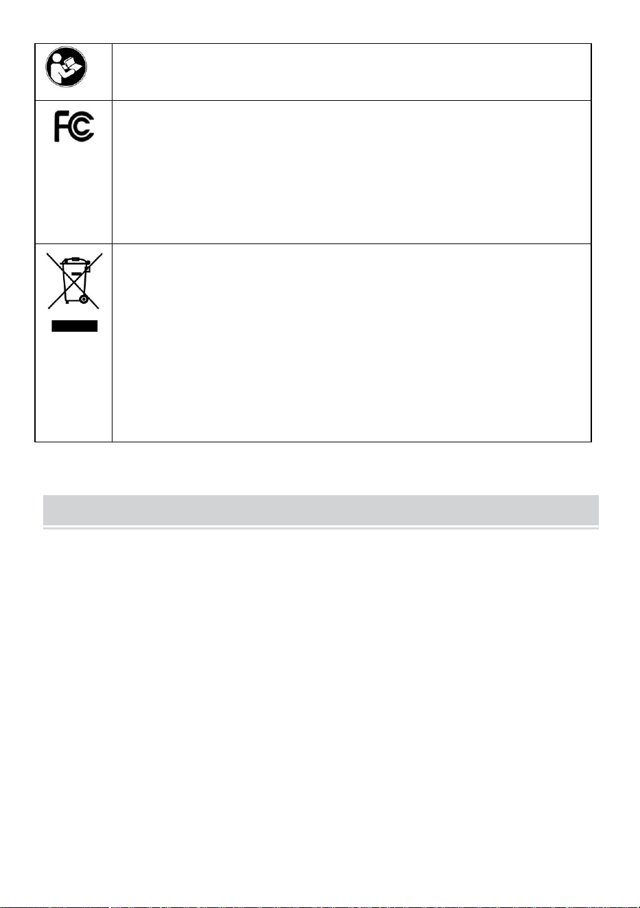
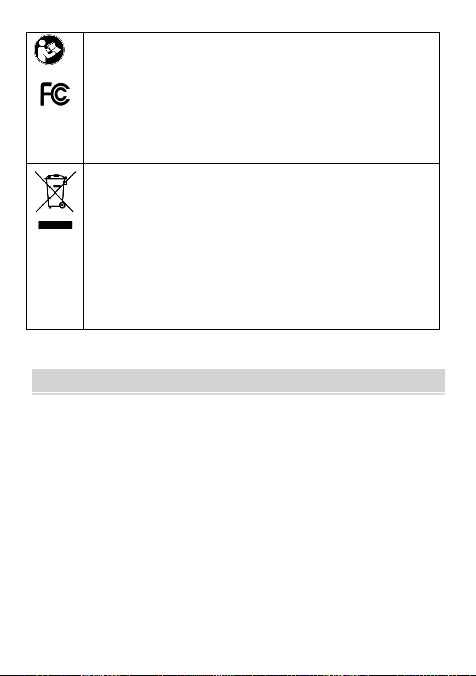
Warning-To reduce the risk of injury, user must read instructions
manual carefully.
This device complies with Part 15 of the FCC Rules. Operation is
subject to the following two conditions:(1)This device may not cause
harmful interference, and (2)this device must accept any interference
received, including interference that may cause undesired operation.
This product is subject to the provision of European Directive
2012/19/EC. The symbol showing a wheelie bin crossed through
indicates that the product requires separate refuse collection in the
European Union. This applies to the product and all accessories
marked with this symbol. Products marked as such may not be
discarded with normal domestic waste, but must be taken to a
collection point for recycling electrical and electronic devices
INSTRUCTIONS
Thank you for choosing our product, please read this operating manual
carefully in order to install and use the product correctly. and keep a safe
place for further use.
The inverter needs to be properly installed and used properly for it to
operate safely. Please read the operating manual carefully before installing
and using it. Pay special attention to these warnings and warning
statements in this manual, warnings about certain conditions and practices
that may damage the inverter, and statements that warn about conditions
of use and practices that may result in personal injury, as well as all
precautions before using the inverter.
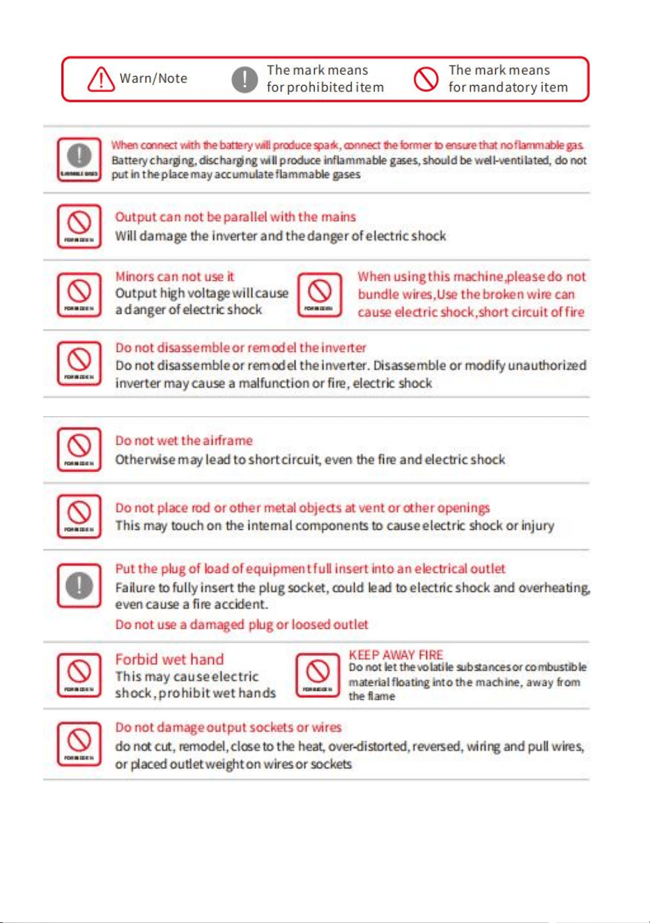
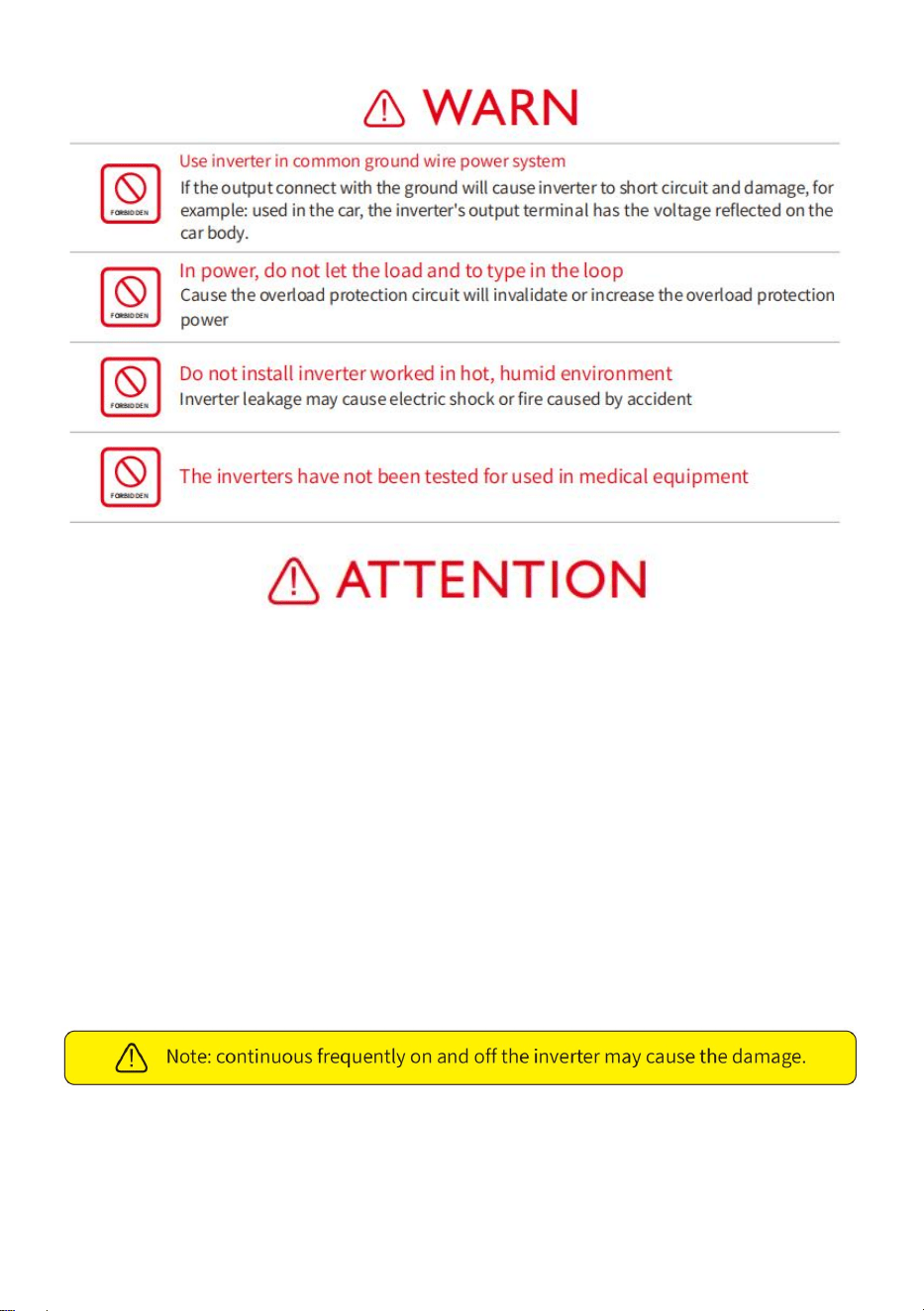
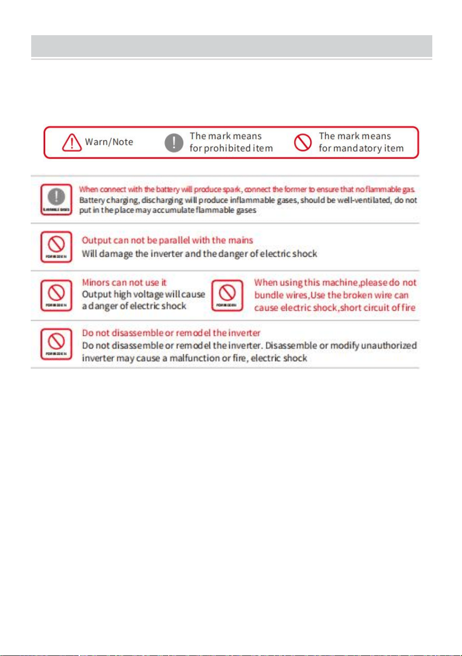
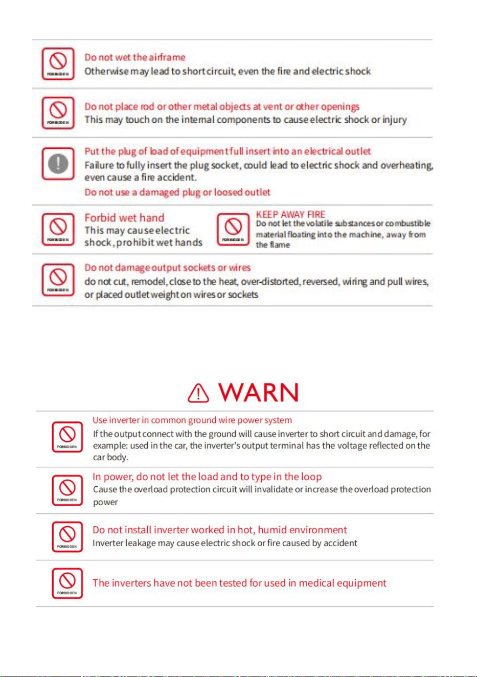
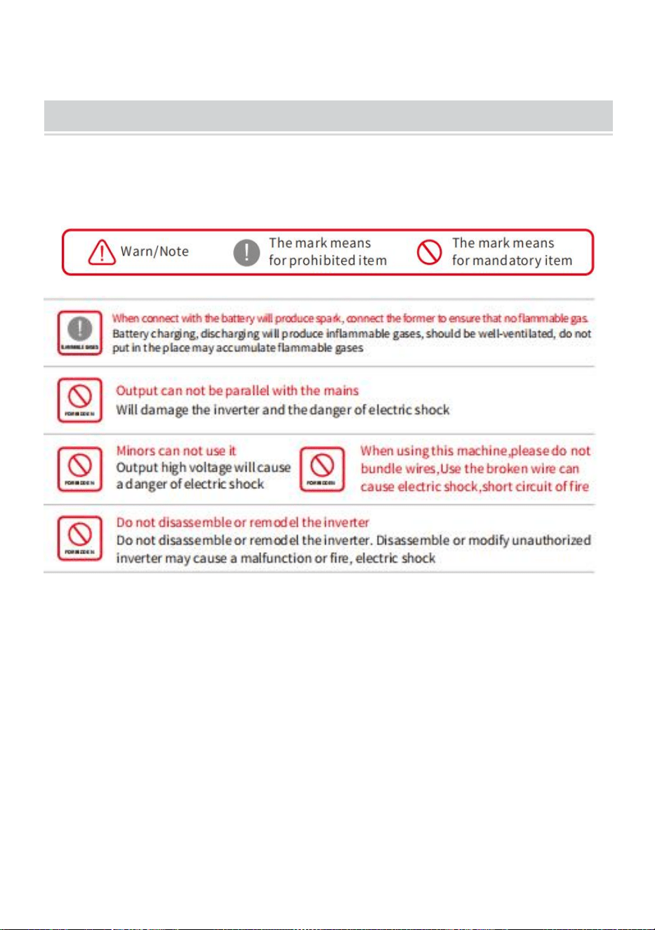
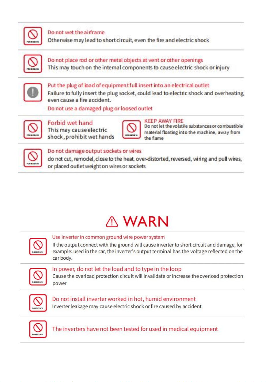
SAFETY NOTICE
In order to avoid causing damage to you and others, please list the
following safety notices here, please ensure to obey and refer to the signs
with the following meanings
- 3 -
- 4 -
Rated current and equipment actually used:
Most power tools, household appliances and audiovisual equipment, in
the power rating range or much lower, but when they are activated UPIT
will be overload protected. The inverter is most likely to drive resistive
loads and switch power loads,Because resistive loads are linear loads that
can work, such as electric stoves, rice cookers, LCD TVs and other
equipment. Partially audiovisual Equipment and power tools require more
power than resistive loads to function properly, Asynchronous motors, CRT
TVs, compressors,pumps and so on. They need 2 to 6 times of the
operating current to start. Whether it can run a specific load depend on the
subject test.
Applied to the following products:
The normal capacity of this product can be used for lamps, rice cookers,
desktop computers, laptops, computer monitors, printers, televisions,
fans, mobile phones, digital products, drilling rigs, electric irons, washing
- 5 -
machines and other original equipment available electricity.
When you use a pump type of load, choose one that has a capacity
greater than more than double the load capacity, and double-check that
the load power you want to use is less than one time the power of our
product.
INTRODUCTION OF PERFORMANCE
The inverter is a power device that can convert direct current (storage
batteries, solar cells, wind energy) into alternating current, and the inverter
uses high-frequency power conversion technology and uses a ferrite
transformer instead of the old bulky silicon steel transformer. That's why
our power inverters are lighter and smaller than other inverters of their kind.
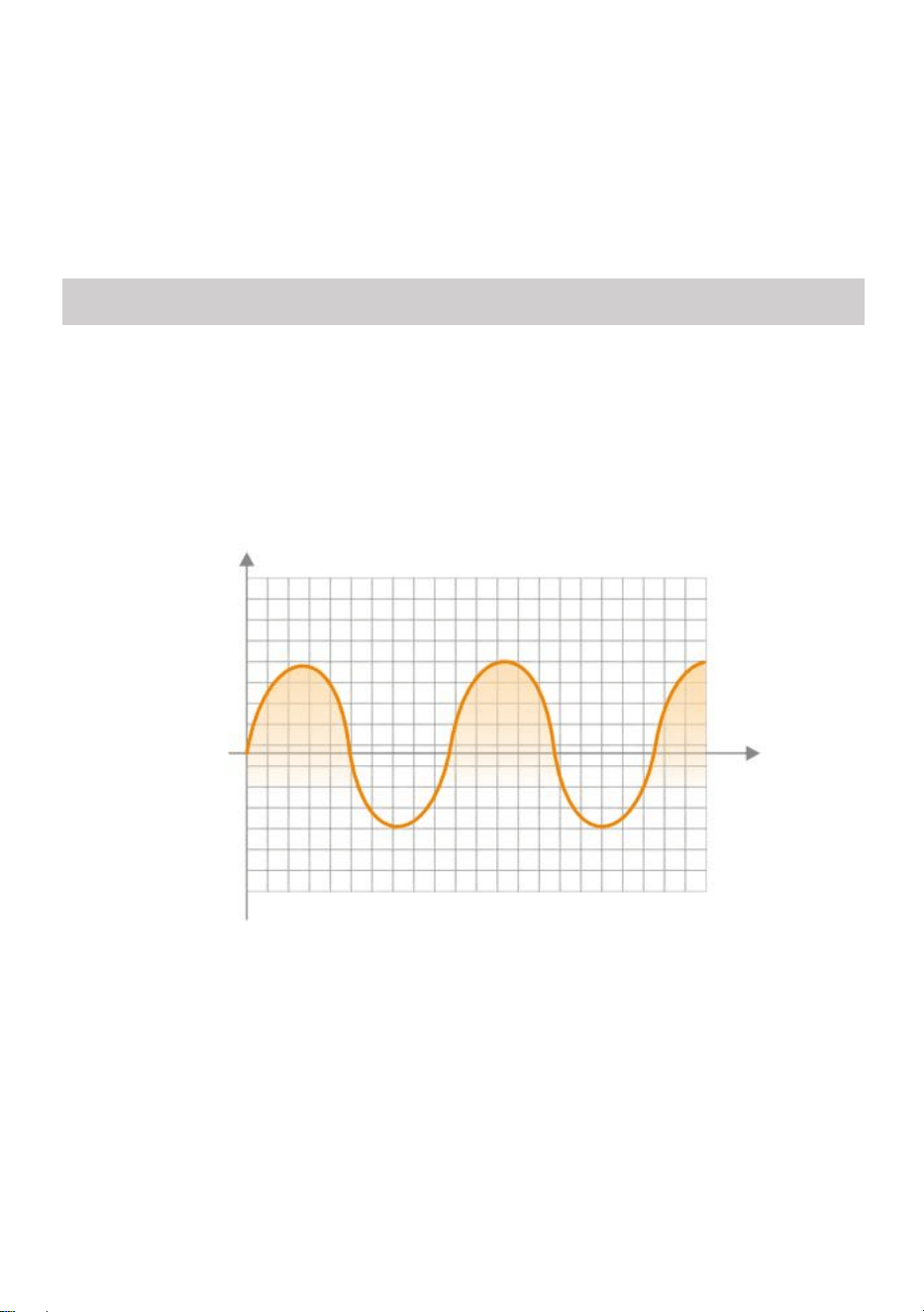
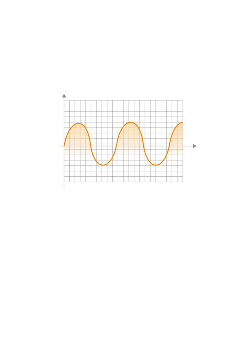
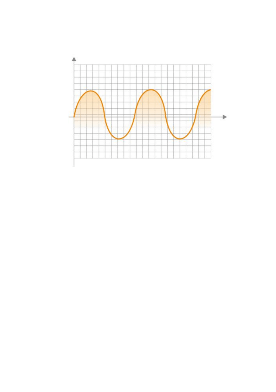
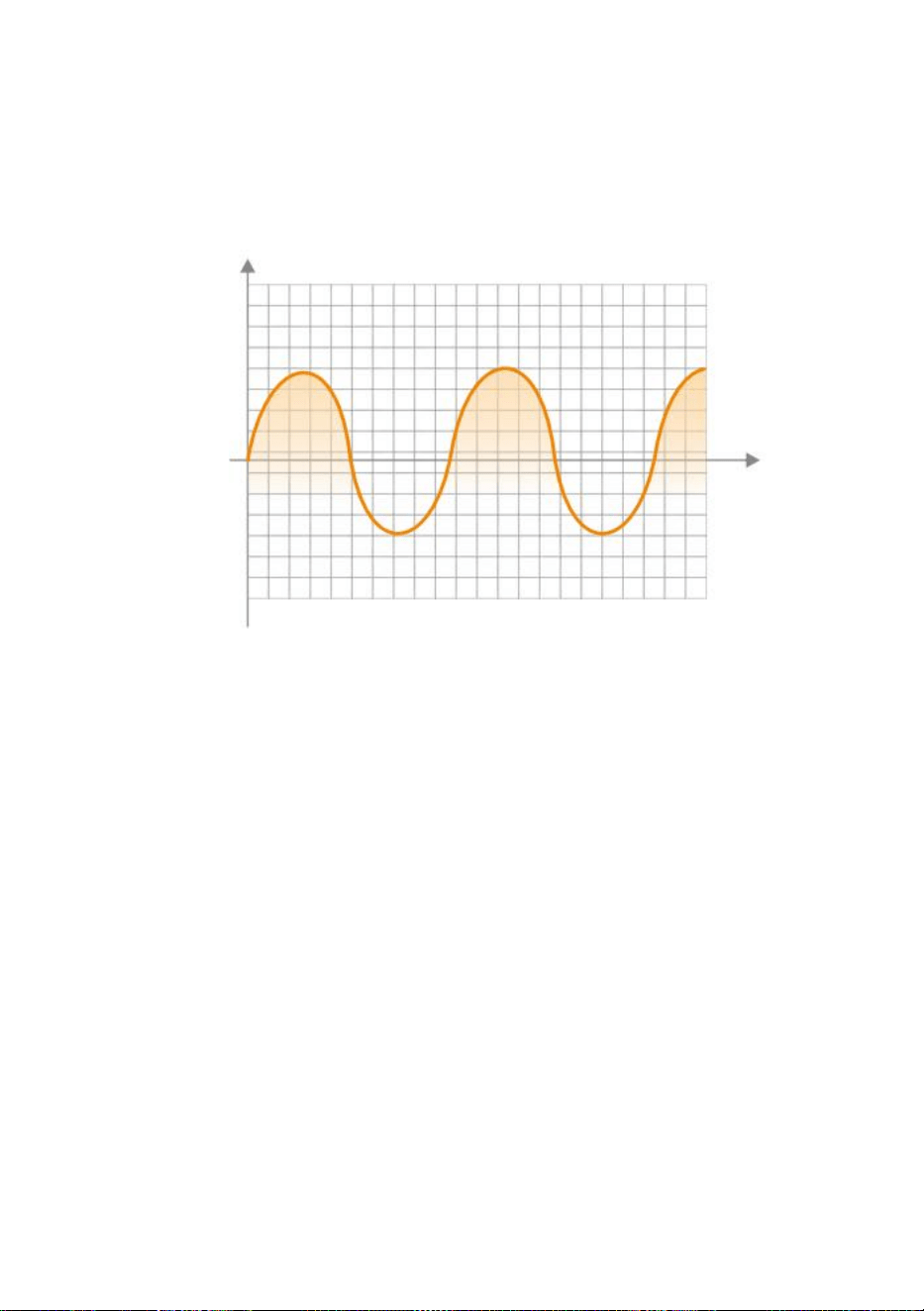
In inverter mode, the output waveform is a sine wave. (See Figure 1).
Figure 1: Output sine waveform
1.Using Environment.
For best use, place the inverter on a flat surface, such as the ground,
car floor, or other solid surfaces where the power cord of the inverter can
be easily fixed.The workplace should meet the following conditions:
Keep it dry, do not let the inverter come into contact with water or other
liquids, keep the inverter Keep away from moisture or water.
Cool environment with a temperature of 0 degrees Celsius To 50 degrees
- 6 -
Celsius, do not place the inverter next to vents or other heated vehicles.
Try to keep the inverter out of direct sunlight.
The surrounding ventilation does not obstruct the surrounding area,
keeping the air flowing freely. Don't put anything on the inverter when
working.
The inverter does not work around combustible materials or flammable
Gases.
The battery can not only provide DC power from 10V to 15V (under a 12V
system), but also have sufficient load current.Lead-acid batteries should
be fully charged, and have a good quality and capacity or lithium
batteries with sufficient discharge current.
High-quality lead-acid batteries and high-capacity lithium batteries have
sufficient discharge current. A rough estimate of the battery's current
capacity is to divide the power of the load by ten (12V system).
Note:For example: if the power of a load is 100W, the current of the
battery100/10=10A must be supplied, this manual does not include all
battery combinations.The specifications of the battery belong to other
areas of technology.
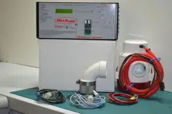
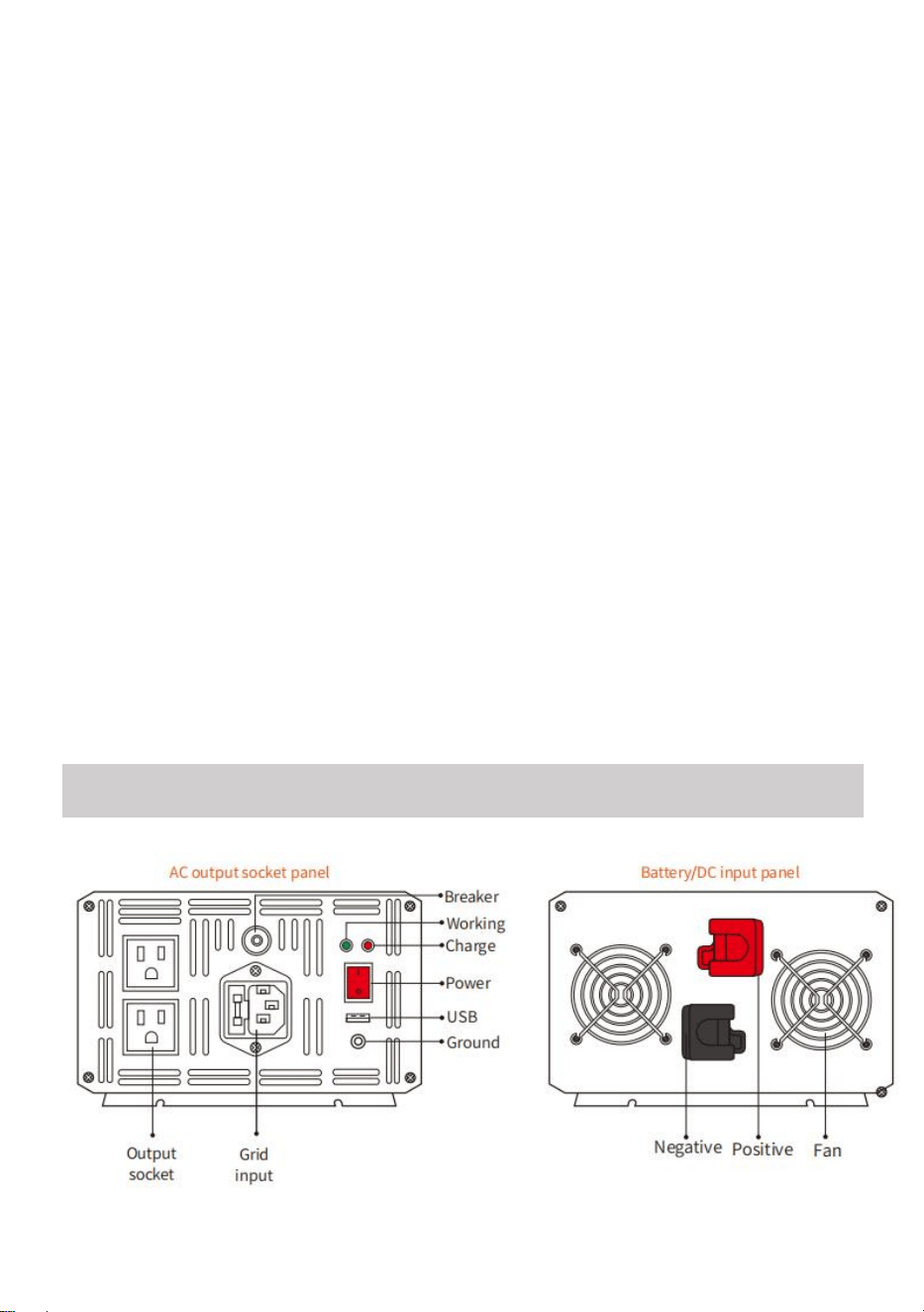
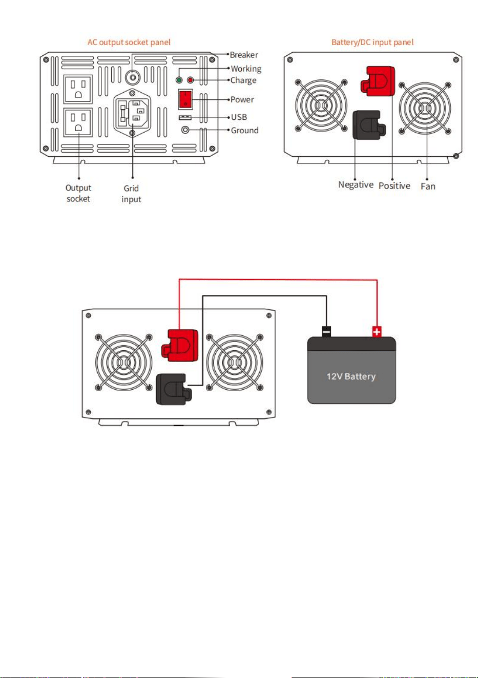
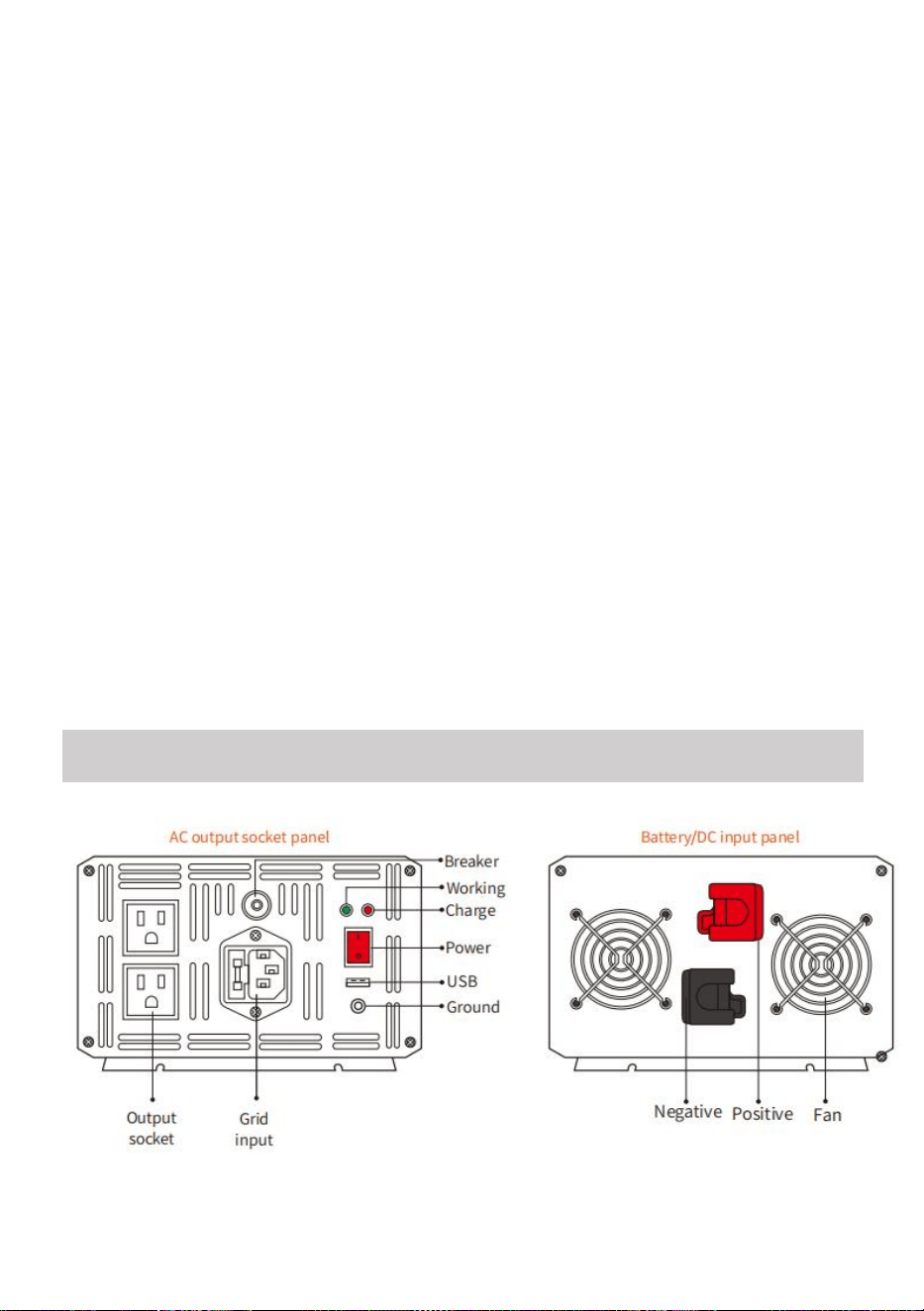
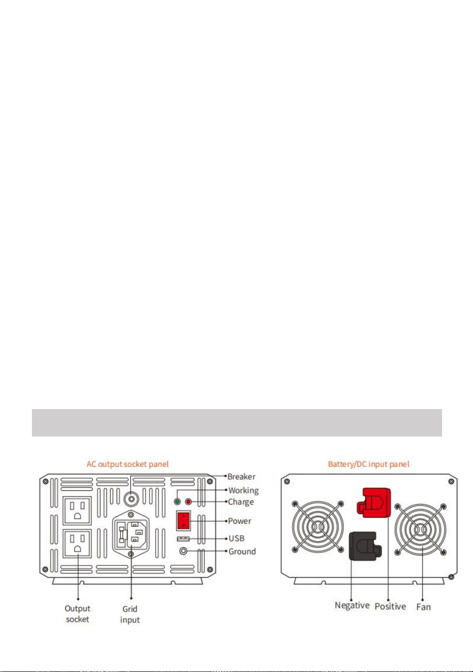
Panel schematic.(See Figure 2)
Figure 2
WITH CHARGING PANEL DESCRIPTION
- 7 -
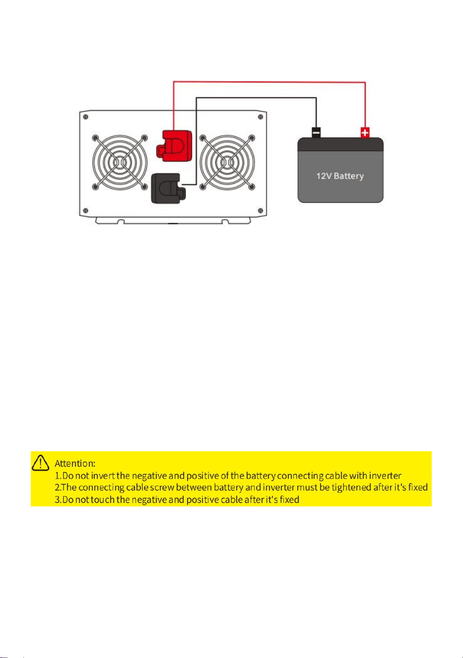
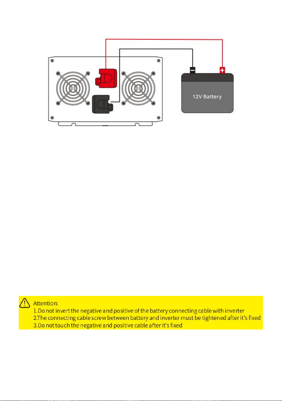
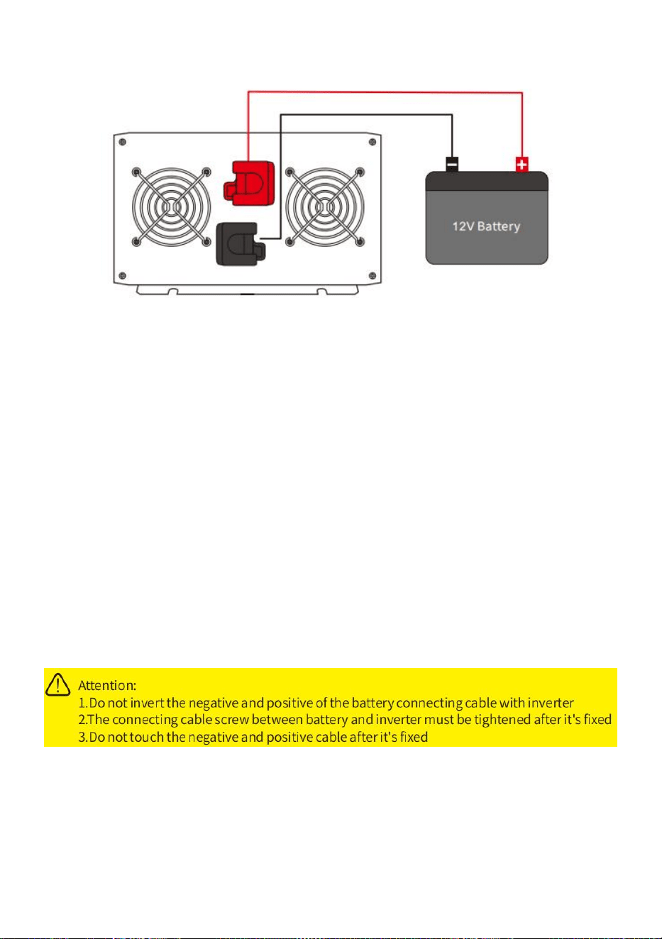
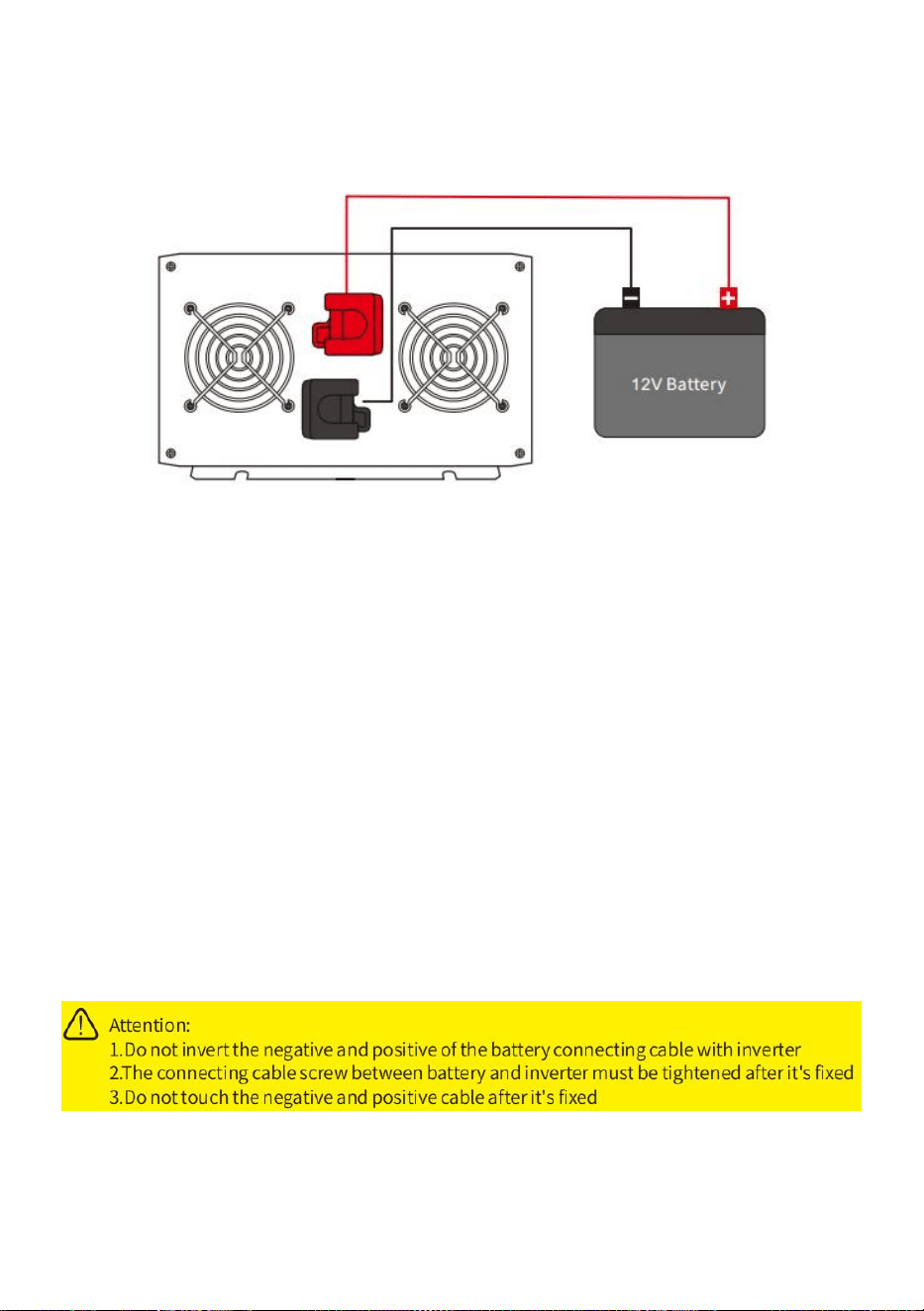
Battery connection diagram.(See Figure3)
Figure3
Installation connection steps.
Please refer to the wiring diagram in Figure 3.
1. First of all, turn off the inverter power.
2. Use a black DC cable to connect the negative pole of the battery to the
black binding post head of the inverter.
3. Use the red DC cable to connect the anode terminal of the battery and
the red post head of the inverter.
4. Plug the electrical devices into the output socket of the inverter.
5. Turn on the inverter switch.
6. Put the AC cable into the grid input socket.
The inverter can use one or more batteries, but it is best to use one or
more batteries Batteries with a capacity of 150AH or above.
Please use the cable sold with the inverter to connect the inverter and
the battery;The red cable connects the anode terminal of the battery and
the red stigma of the inverter,The black cable connects the negative
terminal of the battery and the black stigma of the inverter. Please make

- 8 -
sure all cables are securely fastened. Unsuitable The connection may
cause the cable to overheat and damage to the terminal block, and it will
too Shorten the power supply time of the battery.
Turn on the power switch, the working LED of the inverter will turn red
when the battery is fully charged, and when the inverter is in grid input
mode, the working LED of the inverter will turn green.
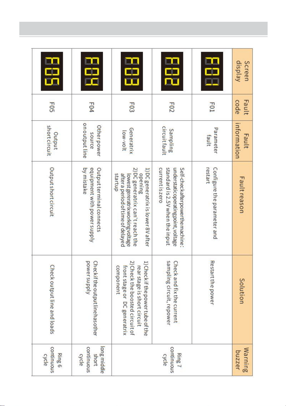
If there is any fault, the LCD display will show a fault icon, and then you
need to check whether the battery voltage is too high or too low, and check
if the inverter output is overloaded or short-circuited.
At the same time, the LCD will also display the fault code, please find out
and check the fault The reason is on page 12-13.
The DC power supply of a 12V inverter can be one 12V battery or
several opposing 12V batteries to increase the power supply time.
Note: The battery voltage connected to the inverter must be the same as
the inverter DC input voltage, such as the 12V inverter should be
connected to the 12V battery, and make sure that all the equipment is
turned off before powering on.
Dismantle steps.
1. First, turn off the inverter power switch.
2. Disconnect the power plug.
3. Dismantle the red DC cable.
4. Dismantle the black DC cable.
5. The done of dismantle.
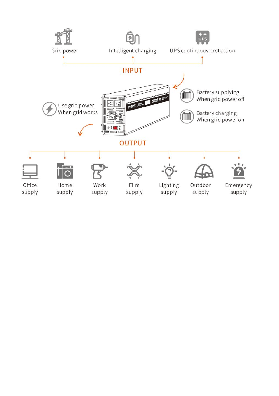
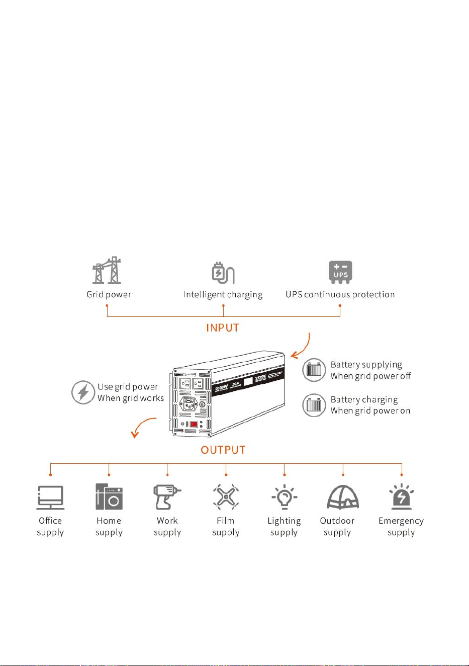
With grid charger and UPS function.
Characteristics of Conventional inverter,Grid power first choice to protect
it powered all the time, grid power and battery switched automatically, UPS
continuous protection.(See Figure4)
- 9 -
Figure4
Feature description:
1. Don't connect the grid power with AC output of the inverter, or it may
destroy the inverter .
2. Grid Mode: When the grid power is connected to the AC input plug, the
AC output socket terminal puts grid power as the first priority.
3. Battery Mode: When the grid power is disconnected from the inverter
AC input, the AC output outlet terminal will automatically output power
from the battery as a second priority.
4. The switching time from grid power to battery power and battery power
to grid power is less than 10ms.
5. In grid mode, the inverter will charge the battery in the mean time, with
3-step charging way.
6. When the battery is charged, the charging red LED lights up, and when
the battery is fully charged,The charging red LED will turn off and the full
green LED will light up.
- 10 -
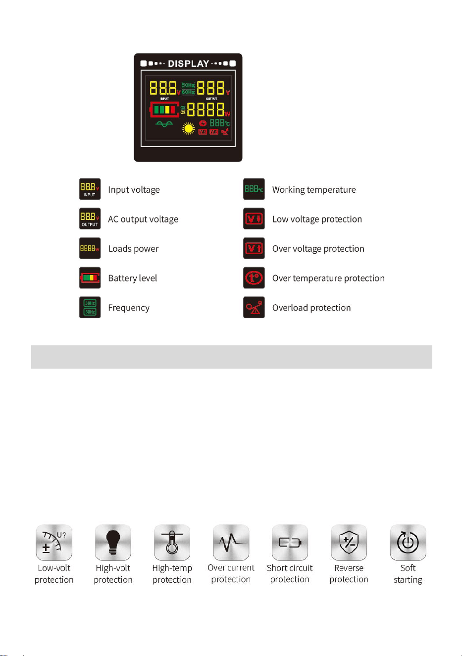
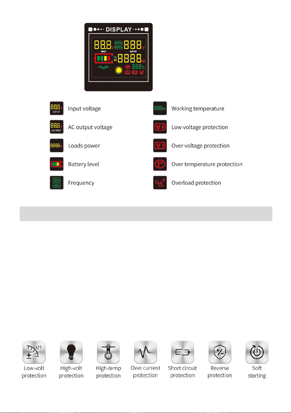
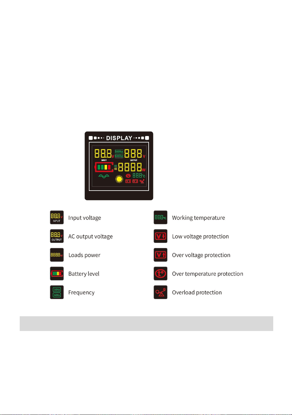
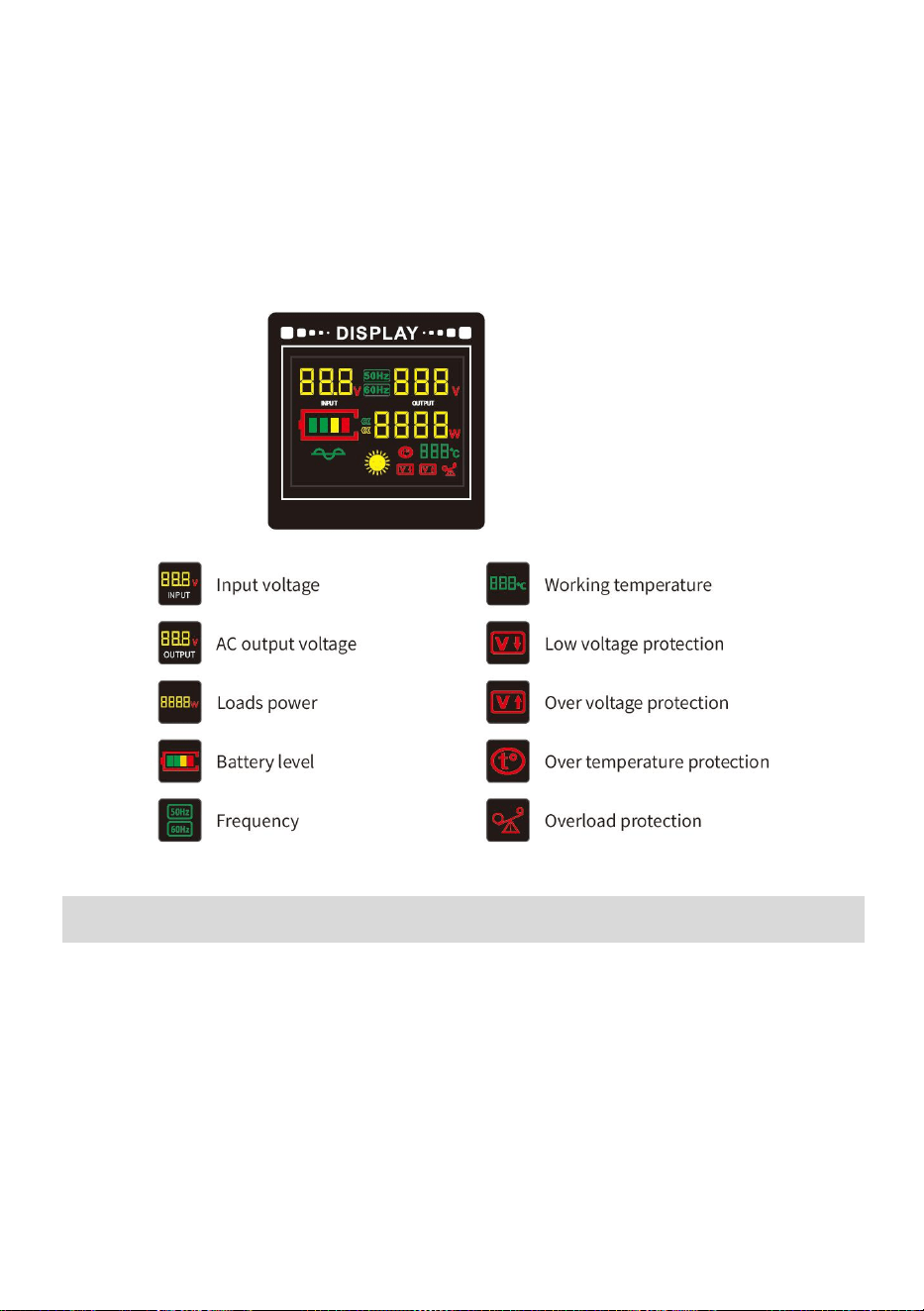
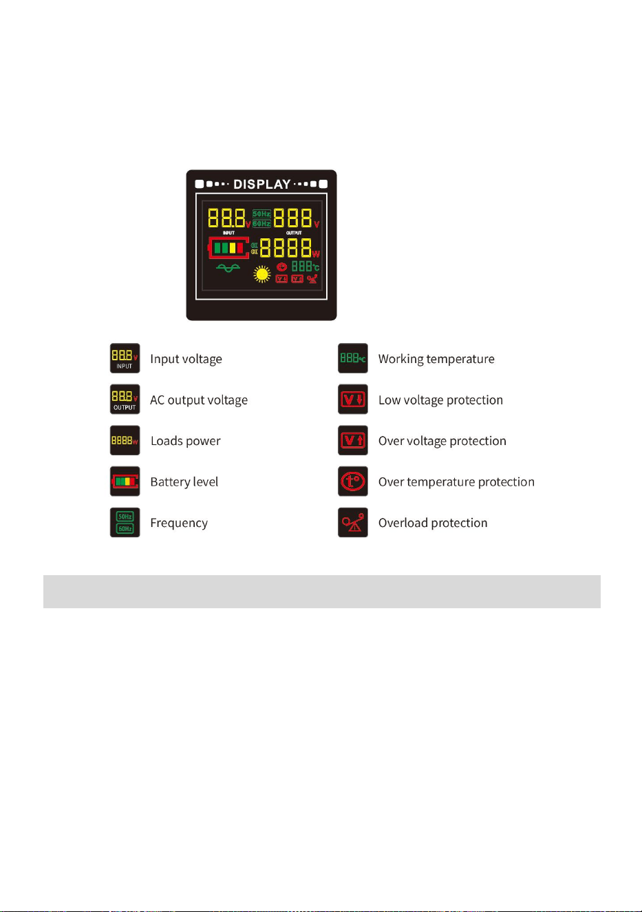
LCD display:(See Figure5)
Figure5
Protection mode
Characteristics(Inverter mode).
Our inverters have perfect protection mechanisms, including battery high
voltage protection, battery low voltage protection, output short circuit protection,
overload protection and battery and load anti-interference protection. The soft start
of the inverter can gradually increase the output voltage, which has the effect of
buffering the inrush current when the high-power electrical appliance is started,
thereby improving the load capacity of the inverter. (A schematic diagram of the
protection function is shown in Figure 6).
Figure 6
- 11 -
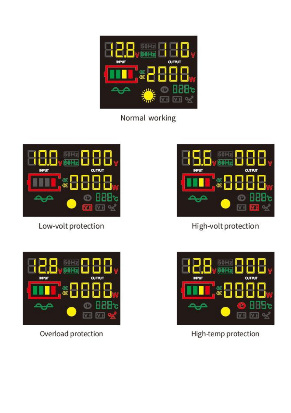
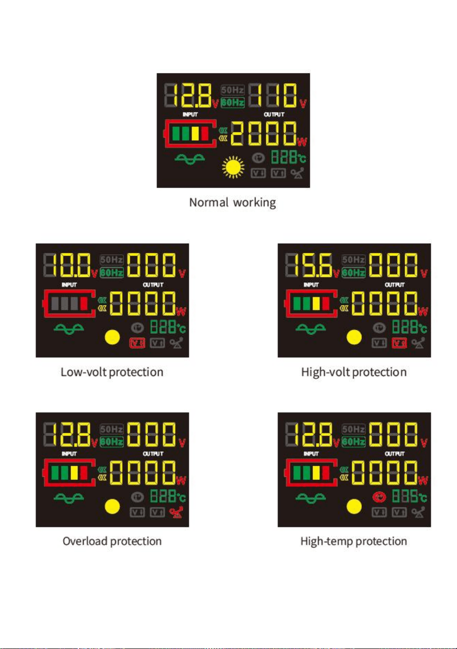
What the display displays in protected mode.(See Figure7)
Figure7
- 12 -
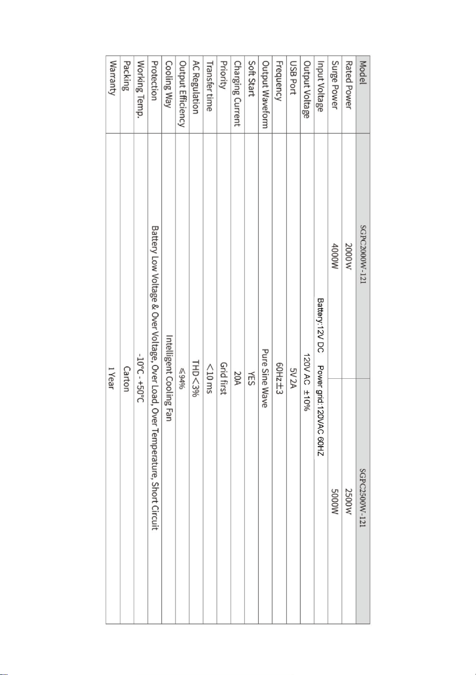
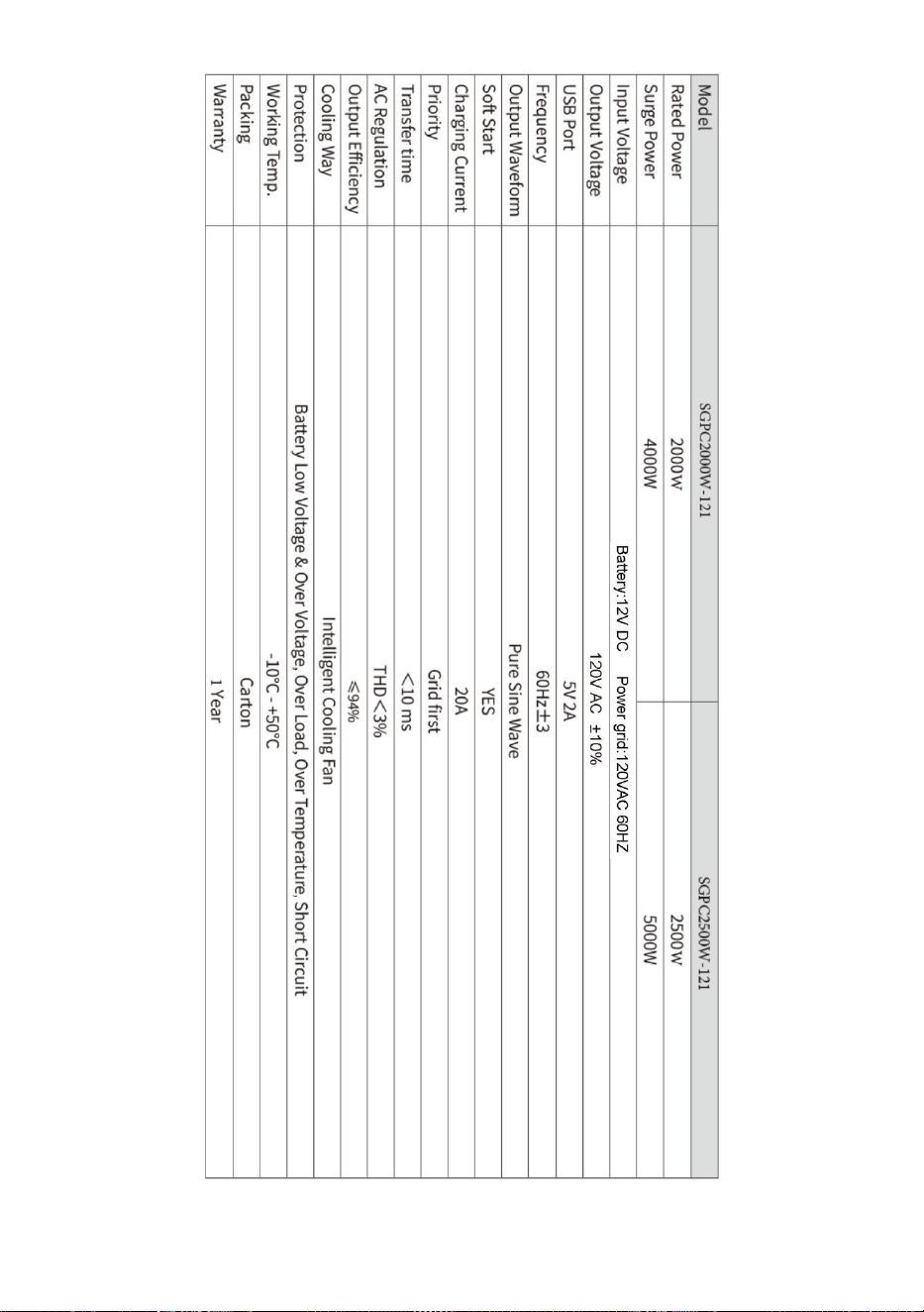
Technical parameters.
- 13 -
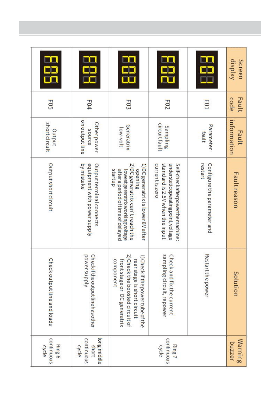
FAULT INFORMATION GUIDE

- 14 -

- 15 -
WARRANTY CARD
To our dear customers:
Thanks for using our inverters, please read & keep the warranty
card to ensure our after-sale warranty.
Warranty Clause.
1. All of our products had passed strict tests before packing, to ensure the
quality & performance.
2. Inverter warranty from the date of purchase: 1 year.
3. When the warranty period is expired, we will offer compensable service
for our products.
Not applicable:
Our products are neither refundable nor exchangeable if they belongs to
the following circumstance:
1. The product damaged by user's improper operation/ maintenance/
storage.
2. Products that have been damaged due to unauthorized removal by the
user or damage caused by non-authorized maintainers of the Company.
3. The user cannot offer the warranty card or valid purchase receipt.
4. Warranty card and product information do not match or the warranty
card has been altered.
5. Damage caused by flood, fire, earthquake or other disasters is not
covered by this warranty. In the above cases, we will provide a
compensable service.
Please fill in the correct product user or company information when
purchasing, and ask the distributor Stamp the warranty card.

- 16 -
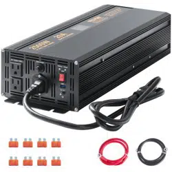
ACCESSORY INFORMATION
1. Operating instructions * 1
2. The battery is connected to the wire * 2
3. 40A DC current fuse:
SGPC2000W-121 * 6
SGPC2500W-121 * 8
4. AC VOLTAGE PLUG WIRE * 1
Battery:12V DC Power grid:120VAC 60HZ
Manufacturer: Shanghaimuxinmuyeyouxiangongsi
Address: Shuangchenglu 803nong11hao1602A-1609shi, baoshanqu,
shanghai 200000 CN.
Imported to AUS: SIHAO PTY LTD, 1 ROKEVA STREETEASTWOOD
NSW 2122 Australia
Imported to USA: Sanven Technology Ltd., Suite 250, 9166 Anaheim
Place, Rancho Cucamonga, CA 91730
REP
EC
E-CrossStu GmbH
Mainzer Landstr.69, 60329 Frankfurt am Main.
REP
UK
YH CONSULTING LIMITED.
C/O YH Consulting Limited Office 147, Centurion House,
London Road, Staines-upon-Thames, Surrey, TW18 4AX


Technique Assistance et certificat de garantie électronique
www.vevor.com/support
ONDULEUR DE POMPE DE PUISARD
MODE D'EMPLOI
MODÈLE : SGPC2000W-121/SGPC2500W-121
We continue to be committed to provide you tools with competitive price.
"Save Half", "Half Price" or any other similar expressions used by us only represents an
estimate of savings you might benefit from buying certain tools with us compared to the major
top brands and does not necessarily mean to cover all categories of tools offered by us. You
are kindly reminded to verify carefully when you are placing an order with us if you are
actually saving half in comparison with the top major brands.


- 1 -
SGPC2000W-121
SGPC2500W-121
Have product questions? Need technical support? Please feel free to
contact us:
Technical Support and E-Warranty Certificate
www.vevor.com/support
NEED HELP? CONTACT US!
This is the original instruction, please read all manual instructions
carefully before operating. VEVOR reserves a clear interpretation of our
user manual. The appearance of the product shall be subject to the
product you received. Please forgive us that we won't inform you again if
there are any technology or software updates on our product.
SUMP PUMP POWER INVERTER
- 2 -
Avertissement : Pour réduire le risque de blessure, l'utilisateur doit
lire attentivement le manuel d'instructions.
Cet appareil est conforme à la partie 15 des règles FCC. Son
fonctionnement est soumis aux deux conditions suivantes : (1) Cet
appareil ne doit pas provoquer d'interférences nuisibles et (2) cet
appareil doit accepter toute interférence reçue, y compris les
interférences susceptibles de provoquer un fonctionnement
indésirable.
Ce produit est soumis aux dispositions de la directive européenne
2012/19/CE. Le symbole représentant une poubelle barrée indique
que le produit nécessite une collecte sélective des déchets dans
l'Union européenne. Ceci s'applique au produit et à tous les
accessoires marqués de ce symbole. Les produits marqués comme
tels ne peuvent pas être jetés avec les ordures ménagères normales,
mais doivent être déposés dans un point de collecte pour le
recyclage des appareils électriques et électroniques.
INSTRUCTIONS
Merci d'avoir choisi notre produit, veuillez lire attentivement ce manuel
d'utilisation afin d'installer et d'utiliser correctement le produit. et
conservez-le dans un endroit sûr pour une utilisation ultérieure.
L'onduleur doit être correctement installé et utilisé correctement pour
fonctionner en toute sécurité. Veuillez lire attentivement le manuel
d'utilisation avant de l'installer et de l'utiliser. Portez une attention
particulière aux avertissements et aux avertissements contenus dans ce
manuel, aux avertissements concernant certaines conditions et pratiques
susceptibles d'endommager l'onduleur et aux déclarations mettant en
garde contre les conditions d'utilisation et les pratiques pouvant entraîner
des blessures corporelles, ainsi qu'à toutes les précautions avant d'utiliser
l'onduleur. onduleur.
- 3 -
SAFETY NOTICE
Afin d'éviter de causer des dommages à vous-même et à autrui, veuillez
lister ici les consignes de sécurité suivantes, veuillez vous assurer d'obéir
et de vous référer aux panneaux avec les significations suivantes
- 4 -
- 5 -
Courant nominal et équipement réellement utilisé :
La plupart des outils électriques, appareils électroménagers et
équipements audiovisuels, dans la plage de puissance nominale ou bien
inférieure, mais lorsqu'ils sont activés UPIT sera protégé contre les
surcharges. L'onduleur est le plus susceptible de piloter des charges
résistives et de commuter des charges de puissance, car les charges
résistives sont des charges linéaires qui peuvent fonctionner, telles que les
cuisinières électriques, les cuiseurs à riz, les téléviseurs LCD et d'autres
équipements. Partiellement audiovisuel Les équipements et outils
électriques nécessitent plus de puissance que les charges résistives pour
fonctionner correctement, Moteurs asynchrones, CRT Téléviseurs,
compresseurs, pompes, etc. Ils ont besoin de 2 à 6 fois le courant de
fonctionnement pour démarrer. La possibilité d'exécuter une charge
spécifique dépend du sujet de test.
Appliqué aux produits suivants :
La capacité normale de ce produit peut être utilisée pour les lampes, les
cuiseurs à riz,
ordinateurs de bureau, ordinateurs portables, écrans d'ordinateur,
imprimantes, téléviseurs, ventilateurs, téléphones portables, produits
numériques, appareils de forage, fers électriques, machines à laver et
autres équipements d'origine disponibles en électricité.
Lorsque vous utilisez une charge de type pompe, choisissez-en une qui a
une capacité
supérieure à plus du double de la capacité de charge et vérifiez que la
puissance de charge que vous souhaitez utiliser est inférieure à une fois
la puissance de notre produit.
INTRODUCTION OF PERFORMANCE
L'onduleur est un dispositif d'alimentation qui peut convertir le courant
- 6 -
continu (batteries de stockage, cellules solaires, énergie éolienne) en
courant alternatif. L'onduleur utilise une technologie de conversion de
puissance à haute fréquence et utilise un transformateur en ferrite au lieu
de l'ancien transformateur encombrant en acier au silicium. C'est pourquoi
nos onduleurs sont plus légers et plus petits que les autres onduleurs de
ce type. En mode inverseur, la forme d ’ onde de sortie est une onde
sinusoïdale. ( Voir Figure 1 ).
Figure 1 : Forme d'onde sinusoïdale de sortie
1.Utilisation de l'environnement.
Pour une utilisation optimale, placez l'onduleur sur une surface plane,
telle que le sol, le plancher d'une voiture ou d'autres surfaces solides où le
cordon d'alimentation de l'onduleur peut être facilement fixé. Le lieu de
travail doit répondre aux conditions suivantes :
Gardez-le au sec, ne laissez pas l'onduleur entrer en contact avec de
l'eau ou d'autres
liquides, gardez l'onduleur Tenir à l'écart de l'humidité ou de l'eau.
Environnement frais avec une température de 0 degré Celsius À 50
degrés
Celsius, ne placez pas l'onduleur à côté de bouches d'aération ou
d'autres véhicules chauffés. Essayez de garder l'onduleur à l'abri de la

- 7 -
lumière directe du soleil.
La ventilation environnante n'obstrue pas les environs,
gardant l'air circulant librement. Ne mettez rien sur l'onduleur lorsque
vous travaillez.
L'onduleur ne fonctionne pas à proximité de matériaux combustibles ou
inflammables
Des gaz .
La batterie peut non seulement fournir une alimentation CC de 10 V à 15
V (sous un courant de 12 V).
système), mais également avoir un courant de charge suffisant. Les
batteries au plomb doivent être complètement chargées et avoir une
bonne qualité et capacité ou des batteries au lithium avec un courant de
décharge suffisant.
Les batteries au plomb de haute qualité et les batteries au lithium de
haute capacité ont
courant de décharge suffisant. Une estimation approximative de la
capacité actuelle de la batterie consiste à diviser la puissance de la
charge par dix (système 12 V).
Remarque : Par exemple : si la puissance d'une charge est de 100 W, le
courant de la batterie doit être fourni 100/10=10 A, ce manuel n'inclut
pas toutes les combinaisons de batteries. Les spécifications de la
batterie appartiennent à d'autres domaines technologiques.
Schéma du panneau . ( Voir Figure 2)
WITH CHARGING PANEL DESCRIPTION
- 8 -
Figure 2
Schéma de connexion de la batterie . ( Voir Figure 3)
figure 3
Étapes de connexion de l'installation .
Veuillez vous référer au schéma de câblage de la figure 3.
7. Tout d'abord, coupez l'alimentation de l'onduleur .
8. Utilisez un câble DC noir pour connecter le pôle négatif de la batterie au
tête de borne noire de l'onduleur.
9. Utilisez le câble DC rouge pour connecter la borne anode de la batterie
et
la tête de poteau rouge de l'onduleur .
10. Branchez les appareils électriques dans la prise de sortie de
l'onduleur.

- 9 -
11. Allumez l'interrupteur de l'onduleur .
12. Branchez le câble CA dans la prise d'entrée du réseau.
L'onduleur peut utiliser une ou plusieurs batteries, mais il est préférable
d'utiliser une ou plusieurs batteries Batteries d'une capacité de 150AH ou
plus.
Veuillez utiliser le câble vendu avec l'onduleur pour connecter l'onduleur
et la batterie ; Le câble rouge relie la borne anode de la batterie et le
stigmate rouge de l'onduleur, Le câble noir relie la borne négative de la
batterie et le stigmate noir de l'onduleur. onduleur. Veuillez vous assurer
que tous les câbles sont solidement fixés. Inapproprié La connexion peut
provoquer une surchauffe du câble et endommager le bornier.
Raccourcissez le temps d'alimentation de la batterie.
Allumez l'interrupteur d'alimentation, la LED de fonctionnement de
l'onduleur deviendra rouge lorsque la batterie est complètement chargée,
et lorsque l'onduleur est en mode d'entrée réseau, la LED de
fonctionnement de l'onduleur deviendra verte.
En cas de défaut, l'écran LCD affichera une icône de défaut, puis vous
devrez vérifier si la tension de la batterie est trop élevée ou trop basse, et
vérifier si la sortie de l'onduleur est surchargée ou court-circuitée.
En même temps, l'écran LCD affichera également le code d'erreur,
veuillez rechercher et vérifier le défaut La raison se trouve à la page 1
2-13 .
L'alimentation CC d'un onduleur 12 V peut être constituée d'une batterie
12 V ou de plusieurs batteries 12 V opposées pour augmenter la durée
d'alimentation.
Remarque : la tension de la batterie connectée à l'onduleur doit être la
même que la tension d'entrée CC de l'onduleur, par exemple l'onduleur 12
V doit être connecté à la batterie 12 V, et assurez-vous que tout
l'équipement est éteint avant de le mettre sous tension.
- 10 -
Démonter les marches .
6. Tout d'abord, éteignez l'interrupteur d'alimentation de l'onduleur.
7. Débranchez la fiche d'alimentation .
8. Démontez le câble DC rouge .
9. Démontez le câble DC noir .
10. Le démontage est terminé .
Avec chargeur réseau et fonction UPS .
Caractéristiques de l'onduleur conventionnel , premier choix
d'alimentation du réseau pour le protéger alimenté en permanence,
alimentation du réseau et batterie commutées automatiquement,
protection continue UPS. ( Voir Figure 4)
Figure 4
Description de fonctionnalité :
7. Ne connectez pas l'alimentation du réseau à la sortie CA de l'onduleur,
car cela pourrait

- 11 -
détruire l'onduleur.
8. Mode réseau : lorsque l'alimentation du réseau est connectée à la prise
d'entrée CA, le
La borne de prise de sortie CA place l’alimentation du réseau comme
première priorité.
9. Mode batterie : lorsque l’alimentation du réseau est déconnectée de l’
onduleur
Entrée CA, la borne de sortie CA produira automatiquement
l'alimentation de la batterie en deuxième priorité.
10. Le temps de commutation de l’alimentation du réseau à l’alimentation
par batterie et à l’alimentation par batterie
à l'alimentation du réseau est inférieure à 10 ms.
11. En mode réseau, l'onduleur chargera la batterie entre-temps, avec
4-manière de chargement par étapes.
12. Lorsque la batterie est chargée, la LED rouge de charge s'allume et
lorsque
la batterie est complètement chargée, la LED rouge de charge s'éteindra
et la LED verte complète s'allumera.
Écran LCD :( Voir Figure 5)
- 12 -
Figure 5
Protection mode
Caractéristiques (mode inverseur ).
Nos onduleurs disposent de mécanismes de protection parfaits, notamment une
protection haute tension de la batterie, une protection basse tension de la batterie,
une protection contre les courts-circuits de sortie, une protection contre les
surcharges et une protection anti-interférence de la batterie et de la charge. Le
démarrage progressif de l'onduleur peut augmenter progressivement la tension de
sortie, ce qui a pour effet de tamponner le courant d'appel lors du démarrage de
l'appareil électrique de haute puissance, améliorant ainsi la capacité de charge de
l'onduleur. (Un diagramme schématique de la fonction de protection est présenté à
la figure 6).
- 13 -
Figure 6
Ce que l'écran affiche en mode protégé . ( Voir Figure 7)
Figure 7

- 14 -
Paramètres techniques .

- 15 -
- 16 -
FAULT INFORMATION GUIDE

- 17 -

- 18 -
WARRANTY CARD
À nos chers clients :
Merci d'utiliser nos onduleurs, veuillez lire et conserver la carte de
garantie pour garantir notre garantie après-vente.
Clause de garantie.
4. Tous nos produits ont passé des tests stricts avant l'emballage, pour
garantir la
performance de qualité.
5. Garantie onduleur à compter de la date d'achat : 1 an.
6. Lorsque la période de garantie est expirée, nous offrirons un service
indemnisable
pour nos produits .
N'est pas applicable:
Nos produits ne sont ni remboursables ni échangeables s'ils
appartiennent à la circonstance suivante :
6. Le produit endommagé par une mauvaise utilisation/entretien/
stockage.
7. Produits qui ont été endommagés en raison d'un retrait non autorisé par
le
utilisateur ou des dommages causés par des mainteneurs non autorisés
de la Société.
8. L'utilisateur ne peut pas offrir la carte de garantie ou le reçu d'achat
valide.
9. La carte de garantie et les informations sur le produit ne correspondent
pas ou la garantie
la carte a été modifiée.
10. Les dommages causés par une inondation, un incendie, un
tremblement de terre ou d'autres catastrophes ne sont pas
couverts par cette garantie. Dans les cas ci-dessus, nous fournirons un

- 19 -
service indemnisable.
Veuillez remplir les informations correctes sur l'utilisateur ou
l'entreprise du produit lors de l'achat et demander au distributeur de
tamponner la carte de garantie.
ACCESSORY INFORMATION
5. Mode d'emploi * 1
6. La batterie est connectée au fil * 2
7. Fusible courant continu 40A :
SGPC2000W-121 * 6
SGPC2500W-121 * 8
8. FIL DE PRISE DE TENSION CA * 1
Batterie : 12 V CC. Réseau électrique : 120 V CA 60 Hz.
Fabricant : Shanghaimuxinmuyeyouxiangongsi
Adresse : Shuangchenglu 803nong11hao1602A-1609shi, baoshanqu,
Shanghai 200000 CN.
Importé en Australie : SIHAO PTY LTD, 1 ROKEVA STREETASTWOOD
NSW 2122 Australie
Importé aux États-Unis : Sanven Technology Ltd., Suite 250, 9166
Anaheim Place, Rancho Cucamonga, CA 91730

- 20 -
REP
EC
E-CrossStu GmbH
Mainzer Landstr.69, 60329 Frankfurt am Main.
REP
UK
YH CONSULTING LIMITED.
C/O YH Consulting Limited Office 147, Centurion House,
London Road, Staines-upon-Thames, Surrey, TW18 4AX


Technisch Support- und E-Garantiezertifikat
www.vevor.com/support
WECHSELRICHTER FÜR SUMPFPUMPE
BEDIENUNGSANLEITUNG
MODELL: SGPC2000W-121/SGPC2500W-121
We continue to be committed to provide you tools with competitive price.
"Save Half", "Half Price" or any other similar expressions used by us only represents an
estimate of savings you might benefit from buying certain tools with us compared to the major
top brands and does not necessarily mean to cover all categories of tools offered by us. You
are kindly reminded to verify carefully when you are placing an order with us if you are
actually saving half in comparison with the top major brands.


- 1 -
SGPC2000W-121
SGPC2500W-121
Have product questions? Need technical support? Please feel free to
contact us:
Technical Support and E-Warranty Certificate
www.vevor.com/support
NEED HELP? CONTACT US!
This is the original instruction, please read all manual instructions
carefully before operating. VEVOR reserves a clear interpretation of our
user manual. The appearance of the product shall be subject to the
product you received. Please forgive us that we won't inform you again if
there are any technology or software updates on our product.
SUMP PUMP POWER INVERTER
- 2 -
Warnung: Um das Verletzungsrisiko zu verringern, muss der
Benutzer die Bedienungsanleitung sorgfältig lesen.
Dieses Gerät entspricht Teil 15 der FCC-Bestimmungen. Der Betrieb
unterliegt den folgenden beiden Bedingungen: (1) Dieses Gerät darf
keine schädlichen Störungen verursachen und (2) dieses Gerät
muss alle empfangenen Störungen akzeptieren, einschließlich
Störungen, die einen unerwünschten Betrieb verursachen können.
Dieses Produkt unterliegt den Bestimmungen der europäischen
Richtlinie 2012/19/EG. Das Symbol einer durchgestrichenen
Mülltonne weist darauf hin, dass das Produkt in der Europäischen
Union einer getrennten Müllsammlung bedarf. Dies gilt für das
Produkt und alle Zubehörteile, die mit diesem Symbol
gekennzeichnet sind. Als solche gekennzeichnete Produkte dürfen
nicht über den normalen Hausmüll entsorgt werden, sondern
müssen an einer Sammelstelle für das Recycling von Elektro- und
Elektronikgeräten abgegeben werden
INSTRUCTIONS
Vielen Dank, dass Sie sich für unser Produkt entschieden haben. Bitte
lesen Sie diese Bedienungsanleitung sorgfältig durch, um das Produkt
richtig zu installieren und zu verwenden. und bewahren Sie einen sicheren
Ort für die weitere Verwendung auf.
Für einen sicheren Betrieb muss der Wechselrichter ordnungsgemäß
installiert und ordnungsgemäß verwendet werden. Bitte lesen Sie die
Bedienungsanleitung sorgfältig durch, bevor Sie es installieren und
verwenden. Achten Sie besonders auf diese Warnungen und
Warnhinweise in diesem Handbuch, auf Warnungen vor bestimmten
Bedingungen und Vorgehensweisen, die zu Schäden am Wechselrichter
führen können, und auf Hinweise, die vor Nutzungsbedingungen und
Vorgehensweisen warnen, die zu Verletzungen führen können, sowie auf
alle Vorsichtsmaßnahmen vor der Verwendung des Wechselrichters
- 3 -
Wandler.
SAFETY NOTICE
Um Schäden für Sie und andere zu vermeiden, führen Sie bitte hier die
folgenden Sicherheitshinweise auf, beachten Sie bitte unbedingt die
Schilder mit der folgenden Bedeutung und beachten Sie diese

- 4 -
- 5 -
Bemessungsstrom und tatsächlich verwendete Ausrüstung:
Die meisten Elektrowerkzeuge, Haushaltsgeräte usw audiovisuelle
Geräte, im Nennleistungsbereich oder viel niedriger, aber wenn sie
aktiviert sind UPIT ist überlastgeschützt. Der Wechselrichter treibt
höchstwahrscheinlich ohmsche Lasten an und schaltet Leistungslasten, da
ohmsche Lasten lineare Lasten sind, die funktionieren können, wie z. B.
Elektroherde, Reiskocher, LCD-Fernseher und andere Geräte. Teilweise
audiovisuell Geräte und Elektrowerkzeuge benötigen mehr Strom als
ohmsche Lasten, um ordnungsgemäß zu funktionieren. Asynchronmotoren,
CRT Fernseher, Kompressoren, Pumpen und so weiter. Sie benötigen zum
Starten das 2- bis 6-fache des Betriebsstroms. Ob eine bestimmte Last
ausgeführt werden kann, hängt vom Testobjekt ab.
Wird auf folgende Produkte angewendet:
Die normale Kapazität dieses Produkts kann für Lampen, Reiskocher,
Desktop-Computer, Laptops, Computermonitore, Drucker, Fernseher,
Ventilatoren, Mobiltelefone, digitale Produkte, Bohrinseln, Bügeleisen,
Waschmaschinen und andere Originalgeräte sind mit Strom
ausgestattet.
Wenn Sie einen Pumpenlasttyp verwenden, wählen Sie einen mit einer
Kapazität
mehr als das Doppelte der Ladekapazität und stellen Sie sicher, dass die
von Ihnen gewünschte Ladeleistung weniger als das Einfache der
Leistung unseres Produkts beträgt.
INTRODUCTION OF PERFORMANCE
Der Wechselrichter ist ein Leistungsgerät, das Gleichstrom (Akkus,
Solarzellen, Windenergie) in Wechselstrom umwandeln kann. Der
Wechselrichter nutzt Hochfrequenz-Leistungsumwandlungstechnologie
und verwendet einen Ferrittransformator anstelle des alten sperrigen
- 6 -
Siliziumstahltransformators. Deshalb sind unsere Wechselrichter leichter
und kleiner als andere Wechselrichter ihrer Art. Im Wechselrichtermodus
ist die Ausgangswellenform eine Sinuswelle. ( Siehe Abbildung 1 ).
Abbildung 1: Sinuswellenform am Ausgang
1. Umgebung nutzen.
Stellen Sie den Wechselrichter für eine optimale Nutzung auf eine
ebene Fläche, z. B. den Boden, den Autoboden oder eine andere feste
Oberfläche, auf der das Netzkabel des Wechselrichters leicht befestigt
werden kann. Der Arbeitsplatz sollte die folgenden Bedingungen erfüllen:
Halten Sie es trocken und lassen Sie den Wechselrichter nicht mit
Wasser oder anderen Dingen in Berührung kommen
Bewahren Sie den Wechselrichter vor Flüssigkeiten auf Von Feuchtigkeit
und Wasser fernhalten.
Kühle Umgebung mit einer Temperatur von 0 Grad Celsius Auf 50 Grad
Stellen Sie den Wechselrichter nicht in der Nähe von Lüftungsschlitzen
oder anderen beheizten Fahrzeugen auf. Versuchen Sie, den
Wechselrichter vor direkter Sonneneinstrahlung zu schützen.
Die umgebende Belüftung behindert die Umgebung nicht.
damit die Luft ungehindert strömen kann. Stellen Sie beim Arbeiten
nichts auf den Wechselrichter.
Der Wechselrichter funktioniert nicht in der Nähe von brennbaren oder
- 7 -
brennbaren Materialien
Gase .
Die Batterie kann nicht nur Gleichstrom von 10 V bis 15 V (unter 12 V)
liefern
System), sondern auch über ausreichenden Ladestrom verfügen.
Blei-Säure-Batterien sollten vollständig geladen sein und über eine gute
Qualität und Kapazität verfügen, bzw. Lithium-Batterien mit
ausreichendem Entladestrom.
Hochwertige Blei-Säure-Batterien und Lithium-Batterien mit hoher
Kapazität
ausreichender Entladestrom. Eine grobe Schätzung der aktuellen
Kapazität der Batterie besteht darin, die Leistung der Last durch zehn zu
teilen (12-V-System).
Hinweis: Wenn beispielsweise die Leistung einer Last 100 W beträgt,
muss der Strom der Batterie 100/10 = 10 A geliefert werden. Dieses
Handbuch umfasst nicht alle Batteriekombinationen. Die Spezifikationen
der Batterie gehören zu anderen Bereichen der Technologie.
Schalttafelschaltplan . ( Siehe Abbildung 2)
Figur 2
WITH CHARGING PANEL DESCRIPTION
- 8 -
Batterieanschlussdiagramm . ( Siehe Abbildung 3)
Figur 3
Installationsverbindungsschritte .
Bitte beachten Sie den Schaltplan in Abbildung 3.
13. Schalten Sie zunächst den Wechselrichter aus .
14. Verwenden Sie ein schwarzes Gleichstromkabel, um den Minuspol der
Batterie mit dem zu verbinden
schwarzen Polklemmenkopf des Wechselrichters.
15. Verwenden Sie das rote Gleichstromkabel, um den Anodenanschluss
der Batterie zu verbinden
der rote Pfostenkopf des Wechselrichters .
16. Stecken Sie die elektrischen Geräte in die Ausgangsbuchse des
Wechselrichters.
17. Schalten Sie den Wechselrichterschalter ein .
18. Stecken Sie das AC-Kabel in die Netzeingangsbuchse.
Der Wechselrichter kann eine oder mehrere Batterien verwenden, am
besten ist es jedoch, eine oder mehrere Batterien zu verwenden Batterien
mit einer Kapazität von 150 Ah oder mehr.
Bitte verwenden Sie das mit dem Wechselrichter gelieferte Kabel, um

- 9 -
den Wechselrichter und die Batterie zu verbinden. Das rote Kabel
verbindet den Anodenanschluss der Batterie und die rote Markierung des
Wechselrichters. Das schwarze Kabel verbindet den Minuspol der Batterie
und die schwarze Markierung des Wandler. Bitte stellen Sie sicher, dass
alle Kabel sicher befestigt sind. Ungeeignet Durch die Verbindung kann es
zu einer Überhitzung des Kabels und zu einer Beschädigung der
Klemmenleiste kommen, was auch der Fall sein wird Verkürzen Sie die
Stromversorgungszeit des Akkus.
Schalten Sie den Netzschalter ein. Die Betriebs-LED des
Wechselrichters leuchtet rot, wenn die Batterie vollständig geladen ist.
Wenn sich der Wechselrichter im Netzeingangsmodus befindet, leuchtet
die Betriebs-LED des Wechselrichters grün.
Wenn ein Fehler vorliegt, zeigt das LCD-Display ein Fehlersymbol an.
Anschließend müssen Sie prüfen, ob die Batteriespannung zu hoch oder
zu niedrig ist und ob der Wechselrichterausgang überlastet oder
kurzgeschlossen ist.
Gleichzeitig zeigt das LCD auch den Fehlercode an. Finden Sie den
Fehler heraus und überprüfen Sie ihn Der Grund steht auf Seite 1 2-13 .
Die Gleichstromversorgung eines 12-V-Wechselrichters kann eine
12-V-Batterie oder mehrere gegenläufige 12-V-Batterien sein, um die
Stromversorgungszeit zu verlängern.
Hinweis: Die an den Wechselrichter angeschlossene Batteriespannung
muss mit der DC-Eingangsspannung des Wechselrichters übereinstimmen,
z. B. sollte der 12-V-Wechselrichter an die 12-V-Batterie angeschlossen
werden. Stellen Sie sicher, dass alle Geräte vor dem Einschalten
ausgeschaltet sind.
Stufen demontieren .
11. Schalten Sie zunächst den Netzschalter des Wechselrichters aus.
12. Ziehen Sie den Netzstecker .
13. Entfernen Sie das rote DC-Kabel .
14. Demontieren Sie das schwarze DC-Kabel .
15. Die Demontage ist abgeschlossen .
Mit Netzladegerät und USV-Funktion .

- 10 -
Eigenschaften des herkömmlichen Wechselrichters :
Netzstromversorgung ist die erste Wahl, um ihn ständig mit Strom zu
versorgen, Netzstrom und Batterie werden automatisch umgeschaltet,
USV-Dauerschutz. ( Siehe Abbildung 4)
Figur 4
Funktionsbeschreibung :
13. Verbinden Sie den Netzstrom nicht mit dem AC-Ausgang des
Wechselrichters, da dies sonst der Fall sein könnte
Zerstören Sie den Wechselrichter.
14. Netzmodus: Wenn der Netzstrom an den AC-Eingangsstecker
angeschlossen ist, wird der
Bei der AC-Ausgangssteckdose hat die Netzstromversorgung oberste
Priorität.
15. Batteriemodus: Wenn die Netzstromversorgung vom Wechselrichter
getrennt ist
AC-Eingang, der AC-Ausgangsausgangsanschluss gibt als zweite
- 11 -
Priorität automatisch Strom aus der Batterie aus.
16. Die Umschaltzeit von Netzstrom auf Batteriestrom und Batteriestrom
zur Netzstromversorgung beträgt weniger als 10 ms.
17. Im Netzbetrieb lädt der Wechselrichter die Batterie in der Zwischenzeit
mit auf
5-Schrittweise Lademethode.
18. Wenn der Akku geladen ist, leuchtet die rote Lade-LED und wann
Der Akku ist vollständig aufgeladen. Die rote Lade-LED erlischt und die
grüne LED für den vollständigen Ladevorgang leuchtet auf.
LCD-Display :( Siehe Abbildung 5)
Abbildung 5
Protection mode
Eigenschaften (Invertermodus ).
Unsere Wechselrichter verfügen über perfekte Schutzmechanismen,
einschließlich Batterie-Hochspannungsschutz, Batterie-Niederspannungsschutz,
Ausgangskurzschlussschutz, Überlastschutz sowie Batterie- und
Last-Entstörungsschutz. Durch den Sanftanlauf des Wechselrichters kann die

- 12 -
Ausgangsspannung schrittweise erhöht werden, wodurch der Einschaltstrom beim
Starten des Hochleistungselektrogeräts gepuffert und so die Belastbarkeit des
Wechselrichters verbessert wird. (Ein schematisches Diagramm der
Schutzfunktion ist in Abbildung 6 dargestellt).
Abbildung 6
Was das Display im geschützten Modus anzeigt . ( Siehe Abbildung 7)

- 13 -
Abbildung 7
Technische Parameter .

- 14 -

- 15 -
FAULT INFORMATION GUIDE

- 16 -

- 17 -
WARRANTY CARD
An unsere lieben Kunden:
Vielen Dank, dass Sie unsere Wechselrichter verwenden. Bitte
lesen Sie die Garantiekarte und bewahren Sie sie auf, um unsere
Garantie nach dem Verkauf zu gewährleisten.
Garantieklausel.
7. Alle unsere Produkte wurden vor dem Verpacken strengen Tests
unterzogen, um dies sicherzustellen
Qualitätsleistung.
8. Wechselrichtergarantie ab Kaufdatum: 1 Jahr.
9. Nach Ablauf der Garantiezeit bieten wir einen vergütbaren Service an
für unsere Produkte .
Unzutreffend:
Unsere Produkte sind weder erstattungsfähig noch umtauschbar, wenn
folgende Umstände vorliegen:
11. Das Produkt wurde durch unsachgemäße
Bedienung/Wartung/Unzulässigkeit des Benutzers beschädigt.
Lagerung.
12. Produkte, die durch unbefugte Entfernung durch den beschädigt
wurden
Benutzer oder Schäden, die durch nicht autorisierte Wartungstechniker
des Unternehmens verursacht wurden.
13. Der Benutzer kann weder die Garantiekarte noch einen gültigen
Kaufbeleg vorlegen.
14. Garantiekarte und Produktinformationen stimmen nicht mit der
Garantie überein
Karte wurde geändert.
15. Schäden, die durch Überschwemmung, Feuer, Erdbeben oder andere
Katastrophen verursacht werden, fallen nicht darunter

- 18 -
von dieser Garantie abgedeckt. In den oben genannten Fällen erbringen
wir eine vergütbare Leistung.
Bitte geben Sie beim Kauf die korrekten Produktbenutzer- oder
Firmeninformationen ein und bitten Sie den Händler, die
Garantiekarte zu stempeln.
ACCESSORY INFORMATION
9. Bedienungsanleitung * 1
10.Die Batterie ist an das Kabel * 2 angeschlossen
11.40A Gleichstromsicherung :
SGPC2000W-121 * 6
SGPC2500W-121 * 8
12.AC-SPANNUNGSSTECKERKABEL * 1
Batterie: 12 V Gleichstrom. Stromnetz: 120 V Wechselstrom, 60 Hz
Hersteller: Shanghaimuxinmuyeyouxiangongsi
Adresse : Shuangchenglu 803nong11hao1602A-1609shi, Baoshanqu,
Shanghai 200000 CN.
Importiert nach AUS: SIHAO PTY LTD, 1 ROKEVA STREETEASTWOOD
NSW 2122 Australien
In die USA importiert: Sanven Technology Ltd., Suite 250, 9166 Anaheim
Place, Rancho Cucamonga, CA 91730

- 19 -
REP
EC
E-CrossStu GmbH
Mainzer Landstr.69, 60329 Frankfurt am Main.
REP
UK
YH CONSULTING LIMITED.
C/O YH Consulting Limited Office 147, Centurion House,
London Road, Staines-upon-Thames, Surrey, TW18 4AX


Tecnico Supporto e certificato di garanzia elettronica
www.vevor.com/support
INVERTITORE DI POTENZA DELLA POMPA DI
RACCOLTA
MANUALE OPERATIVO
MODELLO: SGPC2000W-121/SGPC2500W-121
We continue to be committed to provide you tools with competitive price.
"Save Half", "Half Price" or any other similar expressions used by us only represents an
estimate of savings you might benefit from buying certain tools with us compared to the major
top brands and does not necessarily mean to cover all categories of tools offered by us. You
are kindly reminded to verify carefully when you are placing an order with us if you are
actually saving half in comparison with the top major brands.


- 1 -
SGPC2000W-121
SGPC2500W-121
Have product questions? Need technical support? Please feel free to
contact us:
Technical Support and E-Warranty Certificate
www.vevor.com/support
NEED HELP? CONTACT US!
This is the original instruction, please read all manual instructions
carefully before operating. VEVOR reserves a clear interpretation of our
user manual. The appearance of the product shall be subject to the
product you received. Please forgive us that we won't inform you again if
there are any technology or software updates on our product.
SUMP PUMP POWER INVERTER

- 2 -
Avvertenza: per ridurre il rischio di lesioni, l'utente deve leggere
attentamente il manuale di istruzioni.
Questo dispositivo è conforme alla Parte 15 delle norme FCC. Il
funzionamento è soggetto alle seguenti due condizioni: (1) Questo
dispositivo non può causare interferenze dannose e (2) questo
dispositivo deve accettare qualsiasi interferenza ricevuta, comprese
le interferenze che potrebbero causare un funzionamento
indesiderato.
Questo prodotto è soggetto alle disposizioni della Direttiva Europea
2012/19/CE. Il simbolo del bidone della spazzatura barrato indica
che nell'Unione Europea il prodotto richiede la raccolta differenziata
dei rifiuti. Ciò vale per il prodotto e tutti gli accessori contrassegnati
da questo simbolo. I prodotti contrassegnati come tali non possono
essere smaltiti con i normali rifiuti domestici, ma devono essere
portati in un punto di raccolta per il riciclaggio di dispositivi elettrici ed
elettronici
INSTRUCTIONS
Grazie per aver scelto il nostro prodotto, leggere attentamente questo
manuale operativo per installare e utilizzare correttamente il prodotto. e
conservare un luogo sicuro per un ulteriore utilizzo.
L'inverter deve essere installato e utilizzato correttamente affinché possa
funzionare in sicurezza. Si prega di leggere attentamente il manuale
operativo prima di installarlo e utilizzarlo. Prestare particolare attenzione
agli avvertimenti e alle dichiarazioni di avvertenza contenuti nel presente
manuale, agli avvertimenti su determinate condizioni e pratiche che
potrebbero danneggiare l'inverter e alle dichiarazioni che avvertono sulle
condizioni d'uso e sulle pratiche che potrebbero provocare lesioni
personali, nonché a tutte le precauzioni prima di utilizzare l'inverter.
inverter.

- 3 -
SAFETY NOTICE
Per evitare di causare danni a te e agli altri, elenca qui i seguenti avvisi
di sicurezza, assicurati di obbedire e fare riferimento ai segnali con i
seguenti significati

- 4 -
- 5 -
Corrente nominale e apparecchiature effettivamente utilizzate:
La maggior parte degli utensili elettrici, degli elettrodomestici e
apparecchiature audiovisive, nell'intervallo di potenza nominale o molto
inferiore, ma quando vengono attivati UPIT sarà protetto dal sovraccarico.
È molto probabile che l'inverter guidi carichi resistivi e commuti carichi di
potenza, poiché i carichi resistivi sono carichi lineari che possono
funzionare, come stufe elettriche, cuociriso, TV LCD e altre
apparecchiature. Parzialmente audiovisivo Le apparecchiature e gli utensili
elettrici richiedono più potenza dei carichi resistivi per funzionare
correttamente, Motori asincroni, CRT TV, compressori, pompe e così via.
Richiedono da 2 a 6 volte la corrente operativa per avviarsi. La possibilità
di eseguire un carico specifico dipende dal test in oggetto.
Applicato ai seguenti prodotti:
La capacità normale di questo prodotto può essere utilizzata per
lampade, cuociriso,
computer desktop, laptop, monitor di computer, stampanti, televisori,
ventilatori, telefoni cellulari, prodotti digitali, impianti di perforazione, ferri
da stiro elettrici, lavatrici e altre apparecchiature originali disponibili per
l'elettricità.
Quando si utilizza un tipo di carico a pompa, sceglierne uno che abbia
una capacità
maggiore di più del doppio della capacità di carico e ricontrolla che la
potenza di carico che desideri utilizzare sia inferiore a una volta la
potenza del nostro prodotto.
INTRODUCTION OF PERFORMANCE
L'inverter è un dispositivo di potenza in grado di convertire la corrente
continua (batterie di accumulo, celle solari, energia eolica) in corrente
alternata e l'inverter utilizza la tecnologia di conversione di potenza ad alta

- 6 -
frequenza e utilizza un trasformatore in ferrite invece del vecchio e
ingombrante trasformatore in acciaio al silicio. Ecco perché i nostri inverter
di potenza sono più leggeri e più piccoli degli altri inverter della loro
categoria. In modalità inverter, la forma d'onda di uscita è un'onda
sinusoidale. ( Vedi Figura 1 ).
Figura 1: forma d'onda sinusoidale in uscita
1.Utilizzo dell'ambiente.
Per un utilizzo ottimale, posizionare l'inverter su una superficie piana,
come il suolo, il pavimento dell'auto o altre superfici solide su cui il cavo di
alimentazione dell'inverter possa essere facilmente fissato. Il luogo di
lavoro deve soddisfare le seguenti condizioni:
Tenerlo asciutto, non lasciare che l'inverter entri in contatto con acqua o
altro
liquidi, conservare l'inverter Tenere lontano dall'umidità o dall'acqua.
Ambiente fresco con una temperatura di 0 gradi Celsius A 50 gradi
Celsius, non posizionare l'inverter vicino a prese d'aria o ad altri veicoli
riscaldati. Cercare di tenere l'inverter lontano dalla luce solare diretta.
La ventilazione circostante non ostruisce l'area circostante,
mantenendo l'aria che circola liberamente. Non appoggiare nulla
sull'inverter durante il lavoro.
L'inverter non funziona in prossimità di materiali combustibili o

- 7 -
infiammabili
Gas .
La batteria non solo può fornire alimentazione CC da 10 V a 15 V (sotto i
12 V
sistema), ma avere anche una corrente di carico sufficiente. Le batterie
al piombo devono essere completamente cariche e avere una buona
qualità e capacità oppure batterie al litio con corrente di scarica
sufficiente.
Hanno batterie al piombo-acido di alta qualità e batterie al litio ad alta
capacità
corrente di scarica sufficiente. Una stima approssimativa della capacità
attuale della batteria consiste nel dividere la potenza del carico per dieci
(sistema a 12 V).
Nota: Ad esempio: se la potenza di un carico è 100 W, deve essere
fornita la corrente della batteria 100/10=10 A, questo manuale non
include tutte le combinazioni di batterie. Le specifiche della batteria
appartengono ad altri settori tecnologici.
Schema del pannello . ( Vedi Figura 2)
figura 2
WITH CHARGING PANEL DESCRIPTION
- 8 -
Schema di collegamento della batteria . ( Vedi Figura 3)
Figura 3
Passaggi di connessione dell'installazione .
Fare riferimento allo schema elettrico nella Figura 3.
19. Prima di tutto, spegnere l'alimentazione dell'inverter .
20. Utilizzare un cavo CC nero per collegare il polo negativo della batteria
a
testa di fissaggio nera dell'inverter.
21. Utilizzare il cavo CC rosso per collegare il terminale dell'anodo della
batteria e
la testata rossa dell'inverter .
22. Collegare i dispositivi elettrici alla presa di uscita dell'inverter.
23. Accendere l'interruttore dell'inverter .
24. Inserire il cavo CA nella presa di ingresso della rete.
L'inverter può utilizzare una o più batterie, ma è preferibile utilizzare una
o più batterie Batterie con una capacità di 150 Ah o superiore.
Utilizzare il cavo venduto con l'inverter per collegare l'inverter e la
batteria; Il cavo rosso collega il terminale dell'anodo della batteria e lo
stigma rosso dell'inverter, Il cavo nero collega il terminale negativo della

- 9 -
batteria e lo stigma nero dell'inverter inverter. Assicurati che tutti i cavi
siano fissati saldamente. Inadatto La connessione potrebbe causare il
surriscaldamento del cavo e danni alla morsettiera, e ciò potrebbe
verificarsi anche in questo caso Ridurre il tempo di alimentazione della
batteria.
Accendere l'interruttore di alimentazione, il LED di funzionamento
dell'inverter diventerà rosso quando la batteria è completamente carica e
quando l'inverter è in modalità di ingresso in rete, il LED di funzionamento
dell'inverter diventerà verde.
In caso di guasto, il display LCD mostrerà un'icona di guasto, quindi sarà
necessario verificare se la tensione della batteria è troppo alta o troppo
bassa e verificare se l'uscita dell'inverter è sovraccarica o in cortocircuito.
Allo stesso tempo, il display LCD visualizzerà anche il codice di errore,
individuare e controllare l'errore Il motivo è a pagina 1 2-13 .
L'alimentazione CC di un inverter da 12 V può essere costituita da una
batteria da 12 V o da più batterie da 12 V contrapposte per aumentare il
tempo di alimentazione.
Nota: la tensione della batteria collegata all'inverter deve essere la
stessa della tensione di ingresso CC dell'inverter, ad esempio l'inverter da
12 V deve essere collegato alla batteria da 12 V e assicurarsi che tutte le
apparecchiature siano spente prima di accenderle.
Smontare i passaggi .
16. Innanzitutto, spegnere l'interruttore di alimentazione dell'inverter.
17. Scollegare la spina di alimentazione .
18. Smontare il cavo CC rosso .
19. Smontare il cavo CC nero .
20. Fatto di smantellamento .
Con caricatore di rete e funzione UPS .
Caratteristiche dell'inverter convenzionale , prima scelta
dell'alimentazione di rete per proteggerlo sempre alimentato,
alimentazione di rete e batteria commutate automaticamente, protezione
continua dell'UPS ( vedere Figura 4)

- 10 -
Figura 4
Descrizione delle caratteristiche :
19. Non collegare l'alimentazione di rete all'uscita CA dell'inverter,
altrimenti ciò potrebbe accadere
distruggere l'inverter.
20. Modalità rete: quando l'alimentazione di rete è collegata alla spina di
ingresso CA, il
Il terminale della presa di uscita CA attribuisce all'alimentazione di rete la
massima priorità.
21. Modalità batteria: quando l'alimentazione di rete è disconnessa
dall'inverter
Ingresso CA, il terminale di uscita CA emetterà automaticamente
l'alimentazione dalla batteria come seconda priorità.
22. Il tempo di passaggio dall'alimentazione di rete all'alimentazione a
batteria e all'alimentazione a batteria
alla potenza della rete è inferiore a 10 ms.
- 11 -
23. In modalità rete, l'inverter caricherà nel frattempo la batteria, con
6-modo di ricarica passo-passo.
24. Quando la batteria è carica, il LED rosso di ricarica si accende e
quando
la batteria è completamente carica, il LED rosso di ricarica si spegnerà e
il LED verde completamente si accenderà.
Display LCD :( Vedi Figura 5)
Figura 5
Protection mode
Caratteristiche (modalità inverter ).
I nostri inverter sono dotati di meccanismi di protezione perfetti, tra cui
protezione dall'alta tensione della batteria, protezione dalla bassa tensione della
batteria, protezione da cortocircuito in uscita, protezione da sovraccarico e
protezione anti-interferenza della batteria e del carico. L'avvio graduale
dell'inverter può aumentare gradualmente la tensione di uscita, che ha l'effetto di
tamponare la corrente di spunto quando viene avviato l'apparecchio elettrico ad
alta potenza, migliorando così la capacità di carico dell'inverter. (Un diagramma

- 12 -
schematico della funzione di protezione è mostrato nella Figura 6).
Figura 6
Cosa visualizza il display in modalità protetta . ( Vedi Figura 7)

- 13 -
Figura 7
Parametri tecnici .
- 14 -

- 15 -
FAULT INFORMATION GUIDE

- 16 -

- 17 -
WARRANTY CARD
Ai nostri cari clienti:
Grazie per aver utilizzato i nostri inverter, leggi e conserva la
scheda di garanzia per garantire la nostra garanzia post-vendita.
Clausola di garanzia.
10. Tutti i nostri prodotti hanno superato severi test prima dell'imballaggio,
per garantirne la qualità
qualità e prestazioni.
11. Garanzia inverter dalla data di acquisto: 1 anno.
12. Una volta scaduto il periodo di garanzia, offriremo un servizio
compensabile
per i nostri prodotti .
Non applicabile:
I nostri prodotti non sono né rimborsabili né scambiabili se rientrano
nelle seguenti circostanze:
16. Il prodotto è danneggiato da uso/manutenzione/manutenzione
impropri da parte dell'utente
magazzinaggio.
17. Prodotti che sono stati danneggiati a causa della rimozione non
autorizzata da parte del
utente o danni causati da manutentori non autorizzati dalla Società.
18. L'utente non può offrire la scheda di garanzia o una ricevuta di
acquisto valida.
19. La scheda di garanzia e le informazioni sul prodotto non
corrispondono alla garanzia
la carta è stata alterata.
20. Non lo sono i danni causati da inondazioni, incendi, terremoti o altri
disastri
coperti da questa garanzia. Nei casi di cui sopra, forniremo un servizio

- 18 -
compensabile.
Si prega di inserire le informazioni corrette sull'utente o
sull'azienda del prodotto al momento dell'acquisto e chiedere al
distributore di timbrare la scheda di garanzia.
ACCESSORY INFORMATION
13.Istruzioni per l'uso * 1
14.La batteria è collegata al cavo * 2
15.Fusibile corrente continua da 40 A :
SGPC2000W-121*6
SGPC2500W-121*8
16.CAVO DELLA SPINA DI TENSIONE CA * 1
Batteria: rete elettrica 12V DC: 120VAC 60HZ
Produttore: Shanghaimuxinmuyeyouxiangongsi
Indirizzo : Shuangchenglu 803nong11hao1602A-1609shi, baoshanqu,
shanghai 200000 CN.
Importato in AUS: SIHAO PTY LTD, 1 ROKEVA STREETEASTWOOD
NSW 2122 Australia
Importato negli Stati Uniti: Sanven Technology Ltd., Suite 250, 9166
Anaheim Place, Rancho Cucamonga, CA 91730

- 19 -
REP
EC
E-CrossStu GmbH
Mainzer Landstr.69, 60329 Frankfurt am Main.
REP
UK
YH CONSULTING LIMITED.
C/O YH Consulting Limited Office 147, Centurion House,
London Road, Staines-upon-Thames, Surrey, TW18 4AX


Técnico Certificado de soporte y garantía electrónica
www.vevor.com/support
INVERSOR DE POTENCIA DE BOMBA DE SUMIDERO
OPERACIÓN MANUAL
MODELO: SGPC2000W-121/SGPC2500W-121
We continue to be committed to provide you tools with competitive price.
"Save Half", "Half Price" or any other similar expressions used by us only represents an
estimate of savings you might benefit from buying certain tools with us compared to the major
top brands and does not necessarily mean to cover all categories of tools offered by us. You
are kindly reminded to verify carefully when you are placing an order with us if you are
actually saving half in comparison with the top major brands.

- 1 -
SGPC2000W-121
SGPC2500W-121
Have product questions? Need technical support? Please feel free to
contact us:
Technical Support and E-Warranty Certificate
www.vevor.com/support
NEED HELP? CONTACT US!
This is the original instruction, please read all manual instructions
carefully before operating. VEVOR reserves a clear interpretation of our
user manual. The appearance of the product shall be subject to the
product you received. Please forgive us that we won't inform you again if
there are any technology or software updates on our product.
SUMP PUMP POWER INVERTER

- 2 -
Advertencia: para reducir el riesgo de lesiones, el usuario debe leer
atentamente el manual de instrucciones.
Este dispositivo cumple con la Parte 15 de las normas de la FCC. El
funcionamiento está sujeto a las dos condiciones siguientes: (1) Este
dispositivo no puede causar interferencias dañinas y (2) este
dispositivo debe aceptar cualquier interferencia recibida, incluidas
las interferencias que puedan causar un funcionamiento no
deseado.
Este producto está sujeto a las disposiciones de la Directiva Europea
2012/19/CE. El símbolo que muestra un contenedor con ruedas
tachado indica que el producto requiere recogida selectiva de basura
en la Unión Europea. Esto se aplica al producto y a todos los
accesorios marcados con este símbolo. Los productos marcados
como tales no podrán desecharse con la basura doméstica normal,
sino que deberán llevarse a un punto de recogida para el reciclaje de
aparatos eléctricos y electrónicos.
INSTRUCTIONS
Gracias por elegir nuestro producto. Lea atentamente este manual de
funcionamiento para instalar y utilizar el producto correctamente. y
manténgalo en un lugar seguro para su uso posterior.
El inversor debe instalarse y utilizarse correctamente para que funcione
de forma segura. Lea atentamente el manual de funcionamiento antes de
instalarlo y utilizarlo. Preste especial atención a estas advertencias y
declaraciones de advertencia en este manual, advertencias sobre ciertas
condiciones y prácticas que pueden dañar el inversor y declaraciones que
advierten sobre condiciones de uso y prácticas que pueden resultar en
lesiones personales, así como todas las precauciones antes de usar el
inversor.

- 3 -
SAFETY NOTICE
Para evitar causar daños a usted y a otros, enumere aquí los siguientes
avisos de seguridad, asegúrese de obedecer y consultar las señales con
los siguientes significados.
- 4 -

- 5 -
Corriente nominal y equipo realmente utilizado:
La mayoría de las herramientas eléctricas, electrodomésticos y equipos
audiovisuales, en el rango de potencia nominal o muy inferior, pero cuando
se activan UPIT estará protegido contra sobrecargas. Es más probable
que el inversor impulse cargas resistivas y cambie cargas de energía,
porque las cargas resistivas son cargas lineales que pueden funcionar,
como estufas eléctricas, ollas arroceras, televisores LCD y otros equipos.
Parcialmente audiovisual Los equipos y herramientas eléctricas requieren
más potencia que las cargas resistivas para funcionar correctamente.
Motores asíncronos, CRT Televisores, compresores, bombas, etc.
Necesitan de 2 a 6 veces la corriente operativa para comenzar. Si puede
ejecutar una carga específica depende de la prueba en cuestión.
Aplicado a los siguientes productos:
La capacidad normal de este producto se puede utilizar para lámparas,
ollas arroceras,
Computadoras de escritorio, portátiles, monitores de computadora,
impresoras, televisores, ventiladores, teléfonos móviles, productos
digitales, equipos de perforación, planchas eléctricas, lavadoras y otros
equipos originales con electricidad disponible.
Cuando utilice un tipo de carga de bomba, elija una que tenga una
capacidad
mayor que más del doble de la capacidad de carga, y verifique dos
veces que la potencia de carga que desea utilizar sea menos de una vez
la potencia de nuestro producto.
INTRODUCTION OF PERFORMANCE
El inversor es un dispositivo de energía que puede convertir corriente
continua (baterías de almacenamiento, células solares, energía eólica) en
corriente alterna, y el inversor utiliza tecnología de conversión de energía
- 6 -
de alta frecuencia y utiliza un transformador de ferrita en lugar del viejo y
voluminoso transformador de acero al silicio. Por eso nuestros inversores
de potencia son más ligeros y más pequeños que otros inversores de su
tipo. En modo inversor, la forma de onda de salida es una onda sinusoidal.
( Ver Figura 1 ).
Figura 1: Forma de onda sinusoidal de salida
1.Uso del entorno.
Para un mejor uso, coloque el inversor sobre una superficie plana,
como el suelo, el piso del automóvil u otras superficies sólidas donde el
cable de alimentación del inversor pueda fijarse fácilmente. El lugar de
trabajo debe cumplir las siguientes condiciones:
Manténgalo seco, no permita que el inversor entre en contacto con agua
u otros
líquidos, mantenga el inversor Mantener alejado de la humedad o el
agua.
Ambiente fresco con una temperatura de 0 grados centígrados. a 50
grados
Celsius, no coloque el inversor junto a rejillas de ventilación u otros
vehículos con calefacción. Intente mantener el inversor alejado de la luz
solar directa.
La ventilación circundante no obstruye el área circundante,
- 7 -
manteniendo el aire fluyendo libremente. No coloque nada sobre el
inversor cuando esté trabajando.
El inversor no funciona cerca de materiales combustibles o inflamables.
Gases .
La batería no sólo puede proporcionar alimentación CC de 10 V a 15 V
(bajo una batería de 12 V).
sistema), pero también tener suficiente corriente de carga. Las baterías
de plomo-ácido deben estar completamente cargadas y tener buena
calidad y capacidad o baterías de litio con suficiente corriente de
descarga.
Las baterías de plomo-ácido de alta calidad y las baterías de litio de alta
capacidad tienen
suficiente corriente de descarga. Una estimación aproximada de la
capacidad actual de la batería es dividir la potencia de la carga por diez
(sistema de 12 V).
Nota: Por ejemplo: si la potencia de una carga es de 100W, se debe
suministrar la corriente de la batería 100/10=10A, este manual no
incluye todas las combinaciones de baterías. Las especificaciones de la
batería pertenecen a otras áreas de la tecnología.
Esquema del panel . ( Ver Figura 2)
WITH CHARGING PANEL DESCRIPTION
- 8 -
Figura 2
Diagrama de conexión de la batería . ( Ver Figura 3)
figura 3
Pasos de conexión de instalación .
Consulte el diagrama de cableado en la Figura 3.
25. En primer lugar, apague la alimentación del inversor .
26. Utilice un cable CC negro para conectar el polo negativo de la batería
al
Cabezal de poste de unión negro del inversor.
27. Utilice el cable CC rojo para conectar el terminal del ánodo de la
batería y
el cabezal del poste rojo del inversor .
28. Conecte los dispositivos eléctricos a la toma de salida del inversor.
29. Encienda el interruptor del inversor .
30. Coloque el cable de CA en la toma de entrada de la red.
El inversor puede utilizar una o más baterías, pero lo mejor es utilizar
una o más baterías Baterías con una capacidad de 150AH o superior.
Utilice el cable vendido con el inversor para conectar el inversor y la

- 9 -
batería; el cable rojo conecta el terminal del ánodo de la batería y el
estigma rojo del inversor, el cable negro conecta el terminal negativo de la
batería y el estigma negro del inversor. Asegúrese de que todos los cables
estén bien sujetos. Inadecuado La conexión puede causar que el cable se
sobrecaliente y dañe el bloque de terminales, y también Acorte el tiempo
de suministro de energía de la batería.
Encienda el interruptor de encendido, el LED de funcionamiento del
inversor se volverá rojo cuando la batería esté completamente cargada, y
cuando el inversor esté en modo de entrada de red, el LED de
funcionamiento del inversor se volverá verde.
Si hay alguna falla, la pantalla LCD mostrará un ícono de falla y luego
deberá verificar si el voltaje de la batería es demasiado alto o demasiado
bajo y verificar si la salida del inversor está sobrecargada o en
cortocircuito.
Al mismo tiempo, la pantalla LCD también mostrará el código de falla;
averigüe y verifique la falla. El motivo está en la página 1 2-13 .
La fuente de alimentación CC de un inversor de 12V puede ser una
batería de 12V o varias baterías de 12V opuestas para aumentar el tiempo
de alimentación.
Nota: El voltaje de la batería conectada al inversor debe ser el mismo
que el voltaje de entrada de CC del inversor, por ejemplo, el inversor de 12
V debe conectarse a la batería de 12 V y asegúrese de que todo el equipo
esté apagado antes de encenderlo.
Desmontar pasos .
21. Primero, apague el interruptor de alimentación del inversor.
22. Desconecte el enchufe de alimentación .
23. Desmonte el cable rojo de CC .
24. Desmonte el cable CC negro .
25. El hecho de desmantelar .
Con cargador de red y función UPS .
Características del inversor convencional , primera opción de energía de
red para protegerlo todo el tiempo, energía de red y batería conmutadas
automáticamente, protección continua del UPS. ( Ver Figura 4)

- 10 -
Figura 4
Descripción de la característica :
25. No conecte la red eléctrica con la salida de CA del inversor, o puede
destruir el inversor.
26. Modo de red: cuando la alimentación de la red está conectada al
enchufe de entrada de CA, el
El terminal de salida de CA pone la energía de la red como primera
prioridad.
27. Modo Batería: Cuando la energía de la red se desconecta del inversor
Entrada de CA, el terminal de salida de CA automáticamente emitirá
energía desde la batería como segunda prioridad.
28. El tiempo de cambio de la energía de la red a la energía de la batería y
la energía de la batería.
a la red eléctrica es inferior a 10 ms.
29. En modo red, el inversor cargará la batería mientras tanto, con
7-Modo de carga escalonada.
- 11 -
30. Cuando la batería está cargada, el LED rojo de carga se enciende y
cuando
la batería está completamente cargada, el LED rojo de carga se
apagará y el LED verde completo se encenderá.
Pantalla LCD :( Ver Figura 5)
Figura 5
Protection mode
Características (modo inversor ).
Nuestros inversores tienen mecanismos de protección perfectos, que incluyen
protección de alto voltaje de la batería, protección de bajo voltaje de la batería,
protección contra cortocircuitos de salida, protección contra sobrecarga y
protección antiinterferencias de la batería y la carga. El arranque suave del
inversor puede aumentar gradualmente el voltaje de salida, lo que tiene el efecto
de amortiguar la corriente de entrada cuando se enciende el aparato eléctrico de
alta potencia, mejorando así la capacidad de carga del inversor. (En la Figura 6 se
muestra un diagrama esquemático de la función de protección).

- 12 -
Figura 6
Lo que muestra la pantalla en modo protegido . ( Ver Figura 7)

- 13 -
Figura 7
Parámetros técnicos .

- 14 -

- 15 -
FAULT INFORMATION GUIDE

- 16 -

- 17 -
WARRANTY CARD
A nuestros queridos clientes:
Gracias por utilizar nuestros inversores, lea y conserve la tarjeta de
garantía para garantizar nuestra garantía posventa.
Cláusula de Garantía.
13. Todos nuestros productos han pasado pruebas estrictas antes del
embalaje, para garantizar el
rendimiento de calidad.
14. Garantía del inversor desde la fecha de compra: 1 año.
15. Cuando expire el período de garantía, ofreceremos un servicio
compensable.
para nuestros productos .
No aplica:
Nuestros productos no son reembolsables ni intercambiables si se
encuentran en las siguientes circunstancias:
21. El producto dañado por una operación/mantenimiento/mantenimiento
inadecuados por parte del usuario.
almacenamiento.
22. Productos que hayan resultado dañados debido a una retirada no
autorizada por parte del
usuario o daños causados por mantenedores no autorizados de la
Compañía.
23. El usuario no puede ofrecer la tarjeta de garantía ni el recibo de
compra válido.
24. La tarjeta de garantía y la información del producto no coinciden o la
garantía
La tarjeta ha sido alterada.
25. Los daños causados por inundaciones, incendios, terremotos u otros
desastres no están

- 18 -
cubiertos por esta garantía. En los casos anteriores, proporcionaremos
un servicio compensable.
Complete la información correcta del usuario o de la empresa del
producto al realizar la compra y solicite al distribuidor que selle la
tarjeta de garantía.
ACCESSORY INFORMATION
17.Instrucciones de funcionamiento * 1
18.La batería está conectada al cable * 2
19.Fusible de corriente CC de 40 A :
SGPC2000W-121 * 6
SGPC2500W-121 * 8
20.CABLE DE ENCHUFE DE VOLTAJE CA * 1
Batería: 12V CC Red eléctrica: 120VAC 60HZ
Fabricante: Shanghaimuxinmuyeyouxiangongsi
Dirección : Shuangchenglu 803nong11hao1602A-1609shi, baoshanqu,
shanghai 200000 CN.
Importado a AUS: SIHAO PTY LTD, 1 ROKEVA STREETEASTWOOD
NSW 2122 Australia
Importado a EE. UU.: Sanven Technology Ltd., Suite 250, 9166 Anaheim
Place, Rancho Cucamonga, CA 91730

- 19 -
REP
EC
E-CrossStu GmbH
Mainzer Landstr.69, 60329 Frankfurt am Main.
REP
UK
YH CONSULTING LIMITED.
C/O YH Consulting Limited Office 147, Centurion House,
London Road, Staines-upon-Thames, Surrey, TW18 4AX


Techniczny Certyfikat wsparcia i e-gwarancji
www.vevor.com/support
FALOWNIK ZASILANIA POMPY ŚCIEKOWEJ
INSTRUKCJA OBSŁUGI
MODEL: SGPC2000W-121/SGPC2500W-121
We continue to be committed to provide you tools with competitive price.
"Save Half", "Half Price" or any other similar expressions used by us only represents an
estimate of savings you might benefit from buying certain tools with us compared to the major
top brands and does not necessarily mean to cover all categories of tools offered by us. You
are kindly reminded to verify carefully when you are placing an order with us if you are
actually saving half in comparison with the top major brands.


- 1 -
SGPC2000W-121
SGPC2500W-121
Have product questions? Need technical support? Please feel free to
contact us:
Technical Support and E-Warranty Certificate
www.vevor.com/support
NEED HELP? CONTACT US!
This is the original instruction, please read all manual instructions
carefully before operating. VEVOR reserves a clear interpretation of our
user manual. The appearance of the product shall be subject to the
product you received. Please forgive us that we won't inform you again if
there are any technology or software updates on our product.
SUMP PUMP POWER INVERTER

- 2 -
Ostrzeżenie — aby zmniejszyć ryzyko obrażeń, użytkownik musi
uważnie przeczytać instrukcję obsługi.
To urządzenie jest zgodne z częścią 15 przepisów FCC. Działanie
podlega następującym dwóm warunkom: (1) to urządzenie nie może
powodować szkodliwych zakłóceń oraz (2) to urządzenie musi
akceptować wszelkie odbierane zakłócenia, w tym zakłócenia, które
mogą powodować niepożądane działanie.
Ten produkt podlega przepisom Dyrektywy Europejskiej 2012/19/EC.
Symbol przekreślonego kosza na śmieci oznacza, że produkt
wymaga selektywnej zbiórki śmieci na terenie Unii Europejskiej.
Dotyczy to produktu i wszystkich akcesoriów oznaczonych tym
symbolem. Produktów oznaczonych jako takie nie można wyrzucać
razem ze zwykłymi odpadami domowymi, lecz należy je oddać do
punktu zbiórki w celu recyklingu urządzeń elektrycznych i
elektronicznych
INSTRUCTIONS
Dziękujemy za wybranie naszego produktu. Prosimy o dokładne
zapoznanie się z niniejszą instrukcją obsługi w celu prawidłowego montażu
i użytkowania produktu. i zachować bezpieczne miejsce do dalszego
użycia.
Aby falownik działał bezpiecznie, musi być prawidłowo zainstalowany i
prawidłowo użytkowany. Przed instalacją i użytkowaniem prosimy o
dokładne zapoznanie się z instrukcją obsługi. Należy zwrócić szczególną
uwagę na ostrzeżenia i ostrzeżenia zawarte w niniejszej instrukcji,
ostrzeżenia dotyczące pewnych warunków i praktyk, które mogą
spowodować uszkodzenie falownika, a także oświadczenia ostrzegające o
warunkach użytkowania i praktykach, które mogą skutkować obrażeniami
ciała, a także wszelkie środki ostrożności przed użyciem falownika.
falownik.
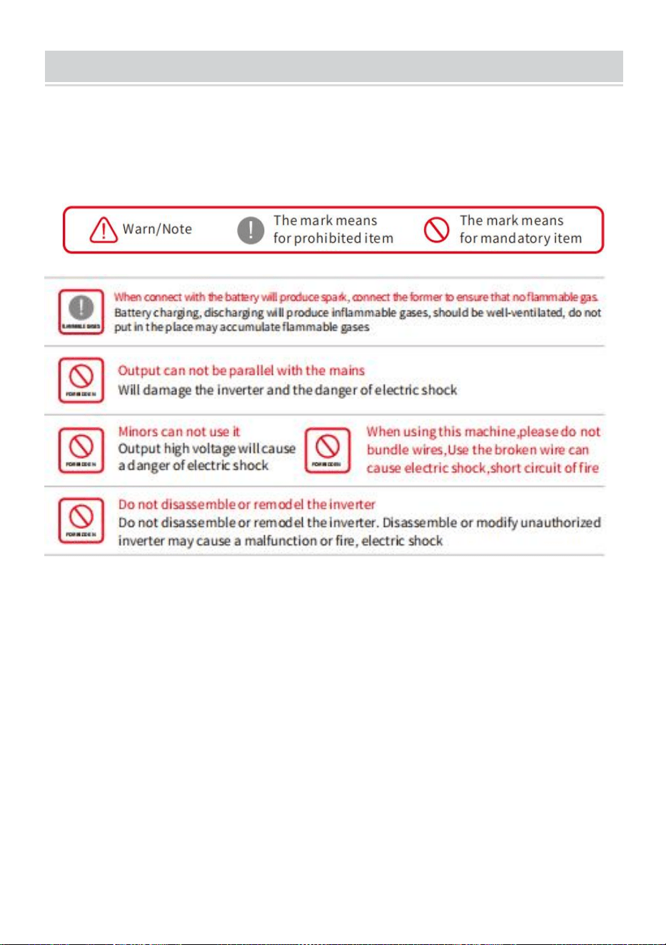
- 3 -
SAFETY NOTICE
Aby uniknąć szkód dla siebie i innych, prosimy o zamieszczenie w tym
miejscu poniższych uwag dotyczących bezpieczeństwa, przestrzeganie ich
i odwoływanie się do znaków o następującym znaczeniu

- 4 -
- 5 -
Prąd znamionowy i faktycznie używany sprzęt:
Większość elektronarzędzi, sprzętu AGD i sprzętu audiowizualnego, w
zakresie mocy znamionowej lub znacznie niższej, ale po ich uruchomieniu
UPIT będzie chroniony przed przeciążeniem. Falownik
najprawdopodobniej napędza obciążenia rezystancyjne i przełącza
obciążenia mocy, ponieważ obciążenia rezystancyjne to obciążenia liniowe,
które mogą działać, takie jak kuchenki elektryczne, urządzenia do
gotowania ryżu, telewizory LCD i inny sprzęt. Częściowo audiowizualne
Sprzęt i elektronarzędzia do prawidłowego działania wymagają większej
mocy niż obciążenia rezystancyjne, Silniki asynchroniczne, CRT
Telewizory, sprężarki, pompy i tak dalej. Do uruchomienia potrzebują od 2
do 6 razy większego prądu roboczego. To, czy może wytrzymać określone
obciążenie, zależy od przedmiotu testu.
Stosowane do następujących produktów:
Normalną pojemność tego produktu można wykorzystać do lamp,
urządzeń do gotowania ryżu,
komputery stacjonarne, laptopy, monitory komputerowe, drukarki,
telewizory, wentylatory, telefony komórkowe, produkty cyfrowe, wiertnice,
żelazka elektryczne, pralki i inny oryginalny sprzęt dostępny na energię
elektryczną.
Jeśli używasz obciążenia typu pompy, wybierz taką, która ma
odpowiednią wydajność
większa niż dwukrotnie większa ładowność i dokładnie sprawdź, czy
moc obciążenia, której chcesz użyć, jest mniejsza niż jednokrotność
mocy naszego produktu.
INTRODUCTION OF PERFORMANCE
Falownik to urządzenie zasilające, które może przekształcać prąd stały
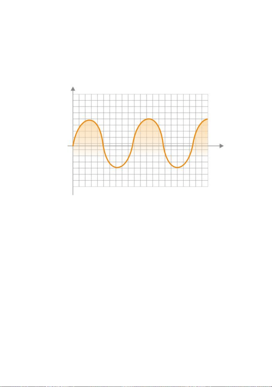
- 6 -
(akumulatory, ogniwa słoneczne, energia wiatrowa) w prąd przemienny, a
falownik wykorzystuje technologię konwersji mocy o wysokiej
częstotliwości i wykorzystuje transformator ferrytowy zamiast starego,
nieporęcznego transformatora ze stali krzemowej. Dlatego nasze falowniki
są lżejsze i mniejsze niż inne falowniki tego typu. W trybie falownika kształt
fali wyjściowej jest falą sinusoidalną. ( Patrz rysunek 1 ).
Rysunek 1: Wyjściowy przebieg sinusoidalny
1. Korzystanie ze środowiska.
W celu najlepszego wykorzystania falownik należy umieścić na
płaskiej powierzchni, takiej jak ziemia, podłoga samochodu lub inna stała
powierzchnia, na której można łatwo przymocować przewód zasilający
falownika. Miejsce pracy powinno spełniać następujące warunki:
Przechowywać w suchym miejscu, nie dopuszczać do kontaktu falownika
z wodą lub innymi substancjami
cieczy, zachowaj falownik Trzymać z dala od wilgoci i wody.
Chłodne otoczenie o temperaturze 0 stopni Celsjusza Do 50 stopni
Celsjusza, nie umieszczaj falownika w pobliżu otworów wentylacyjnych
lub innych ogrzewanych pojazdów. Staraj się trzymać falownik z dala od
bezpośredniego światła słonecznego.
Wentylacja otoczenia nie zakłóca otoczenia,
utrzymując swobodny przepływ powietrza. Podczas pracy nie kładź
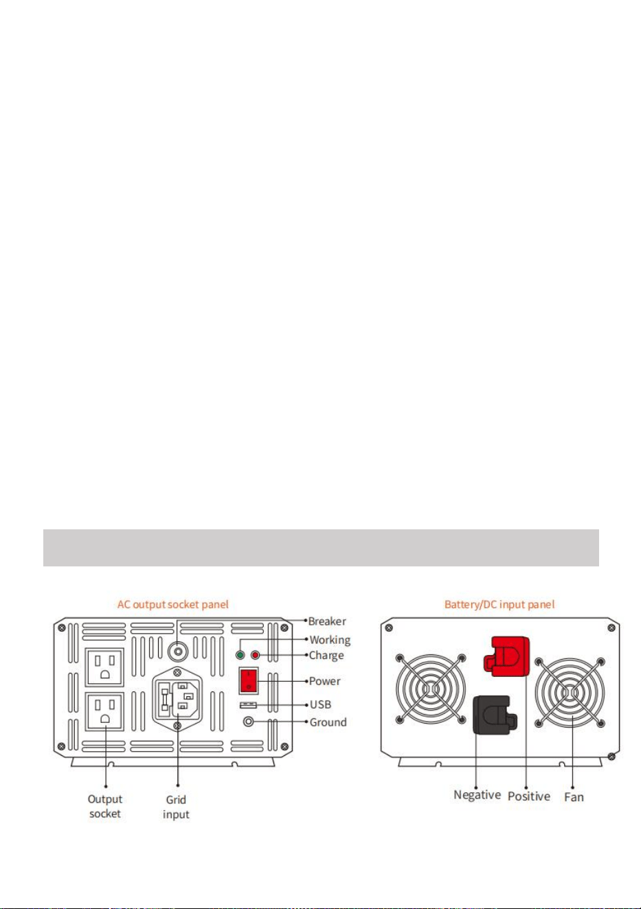
- 7 -
niczego na falowniku.
Falownik nie pracuje w pobliżu materiałów palnych lub łatwopalnych
Gazy .
Bateria może nie tylko dostarczać prąd stały od 10 V do 15 V (poniżej 12
V
systemu), ale także posiadać wystarczający prąd obciążenia.
Akumulatory kwasowo-ołowiowe powinny być w pełni naładowane,
dobrej jakości i pojemności, lub akumulatory litowe o wystarczającym
prądzie rozładowania.
Wysokiej jakości akumulatory kwasowo-ołowiowe i akumulatory litowe o
dużej pojemności
wystarczający prąd rozładowania. Przybliżona pojemność prądowa
akumulatora polega na podzieleniu mocy obciążenia przez dziesięć
(system 12 V).
Uwaga: Na przykład: jeśli moc obciążenia wynosi 100 W, akumulator
musi być zasilany prądem 100/10 = 10 A, niniejsza instrukcja nie
obejmuje wszystkich kombinacji akumulatorów. Specyfikacje
akumulatora należą do innych obszarów technologii.
Schemat panelu . ( Patrz rysunek 2)
Rysunek 2
WITH CHARGING PANEL DESCRIPTION
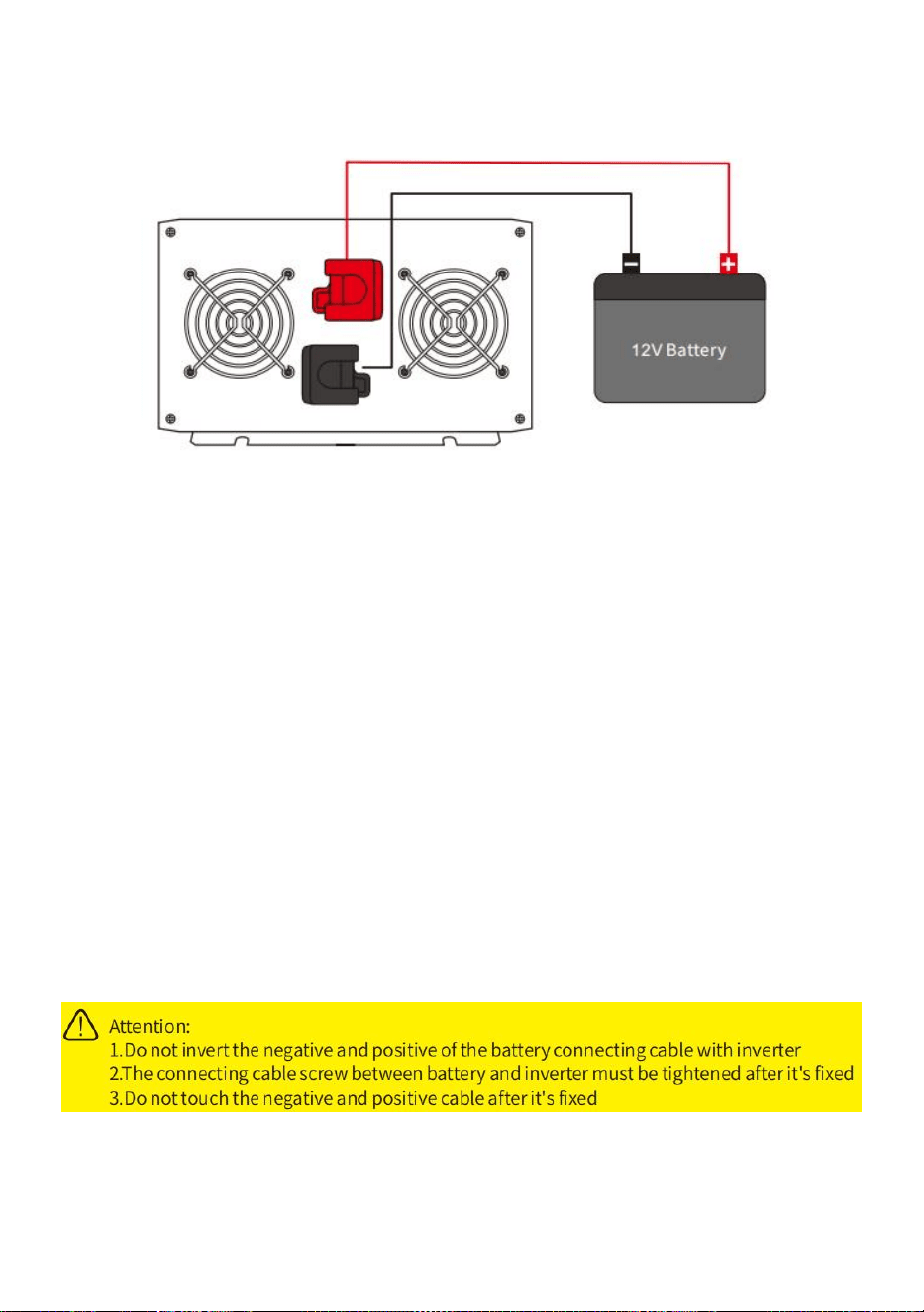
- 8 -
Schemat podłączenia akumulatora . ( Patrz rysunek 3)
Rysunek 3
Kroki podłączenia instalacji .
Proszę zapoznać się ze schematem połączeń na rysunku 3.
31. W pierwszej kolejności należy wyłączyć zasilanie falownika .
32. Użyj czarnego kabla prądu stałego, aby podłączyć biegun ujemny
akumulatora do
czarna głowica słupkowa falownika.
33. Za pomocą czerwonego kabla prądu stałego podłącz zacisk anodowy
akumulatora i
czerwona główka słupka falownika .
34. Podłącz urządzenia elektryczne do gniazda wyjściowego falownika.
35. Włącz przełącznik falownika .
36. Włóż kabel prądu przemiennego do gniazda wejściowego sieci.
Falownik może wykorzystywać jeden lub więcej akumulatorów, jednak
najlepiej jest używać jednego lub więcej akumulatorów Baterie o
pojemności 150AH lub większej.

- 9 -
Do podłączenia falownika i akumulatora należy używać kabla
sprzedawanego wraz z falownikiem. Czerwony kabel łączy zacisk
anodowy akumulatora z czerwonym piętnem falownika. Czarny kabel łączy
ujemny biegun akumulatora z czarnym piętnem akumulatora. falownik.
Upewnij się, że wszystkie kable są dobrze zamocowane. Nieodpowiedni
Połączenie może spowodować przegrzanie kabla i uszkodzenie listwy
zaciskowej, co również będzie miało miejsce Skróć czas zasilania
akumulatora.
Włącz wyłącznik zasilania, dioda robocza falownika zmieni kolor na
czerwony, gdy akumulator będzie w pełni naładowany, a gdy falownik
znajdzie się w trybie wejścia do sieci, dioda robocza falownika zmieni kolor
na zielony.
Jeżeli wystąpi jakakolwiek usterka, na wyświetlaczu LCD pojawi się
ikona usterki, następnie należy sprawdzić, czy napięcie akumulatora nie
jest za wysokie, czy za niskie oraz czy wyjście falownika nie jest
przeciążone lub zwarte.
W tym samym czasie wyświetlacz LCD wyświetli również kod błędu.
Znajdź i sprawdź usterkę Powód znajduje się na stronie 1 2-13 .
Zasilanie prądem stałym falownika 12 V może stanowić jeden
akumulator 12 V lub kilka przeciwstawnych akumulatorów 12 V, aby
wydłużyć czas zasilania.
Uwaga: Napięcie akumulatora podłączonego do falownika musi być
takie samo, jak napięcie wejściowe prądu stałego falownika, np. falownik
12 V powinien być podłączony do akumulatora 12 V. Przed włączeniem
zasilania należy upewnić się, że cały sprzęt jest wyłączony.
Zdemontować stopnie .
26. Najpierw wyłącz wyłącznik zasilania falownika.
27. Odłącz wtyczkę zasilania .
28. Zdemontuj czerwony kabel prądu stałego .
29. Zdemontuj czarny kabel prądu stałego .
30. Zakończono demontaż .
Z ładowarką sieciową i funkcją UPS .
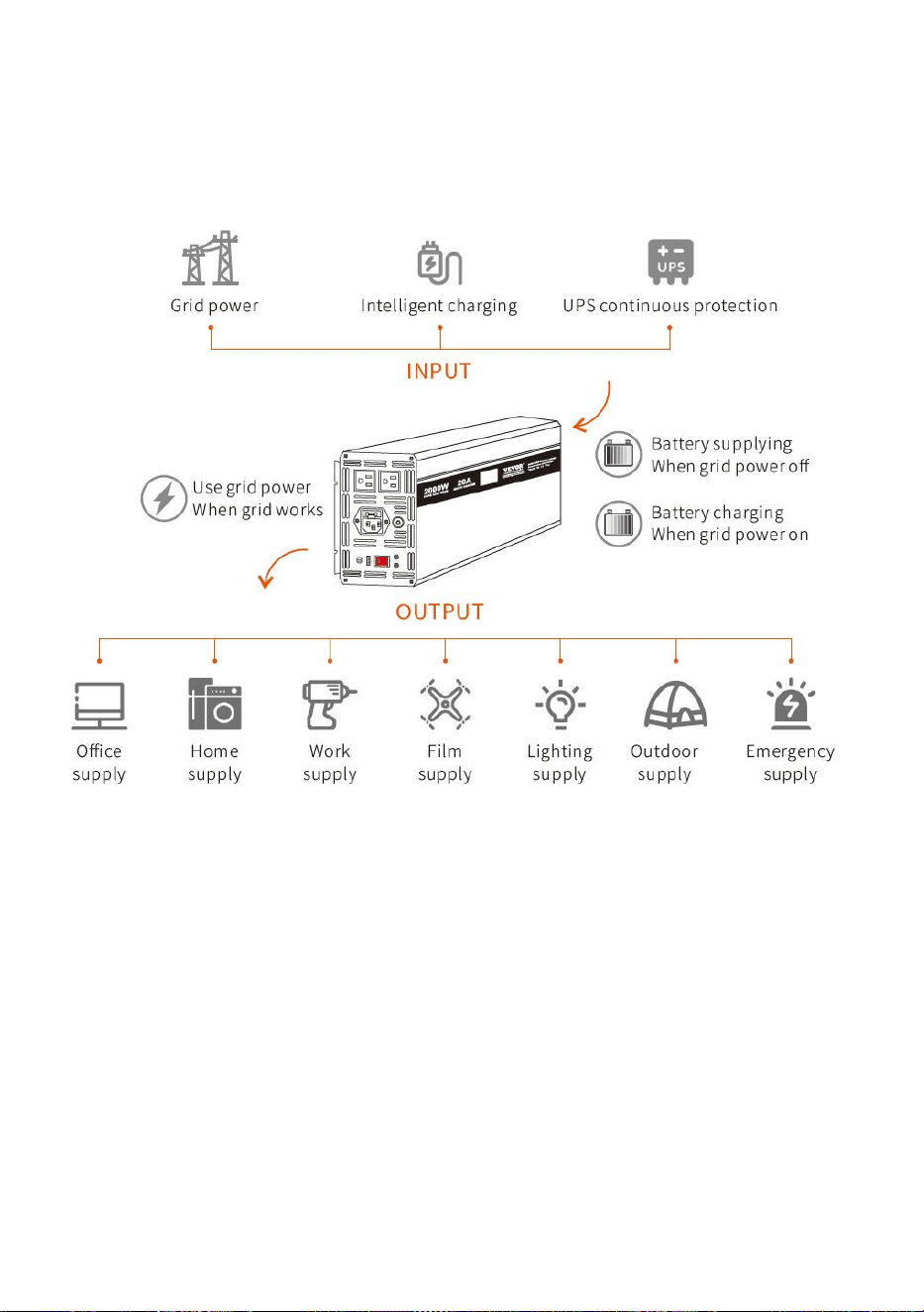
- 10 -
Charakterystyka konwencjonalnego falownika , pierwszy wybór zasilania
sieciowego, aby chronić go przez cały czas, zasilanie sieciowe i
akumulator przełączane automatycznie, ciągła ochrona UPS. ( patrz
rysunek 4)
Rysunek 4
Opis funkcji :
31. Nie podłączaj zasilania sieciowego do wyjścia AC falownika, gdyż
może to spowodować
zniszczyć falownik.
32. Tryb sieciowy: Gdy zasilanie sieciowe jest podłączone do wtyczki
wejściowej AC,
Terminal gniazda wyjściowego AC stawia zasilanie sieciowe na
pierwszym miejscu.
33. Tryb akumulatorowy: Gdy zasilanie sieciowe jest odłączone od
falownika
Wejście AC, terminal wyjściowy AC automatycznie wyprowadza moc z
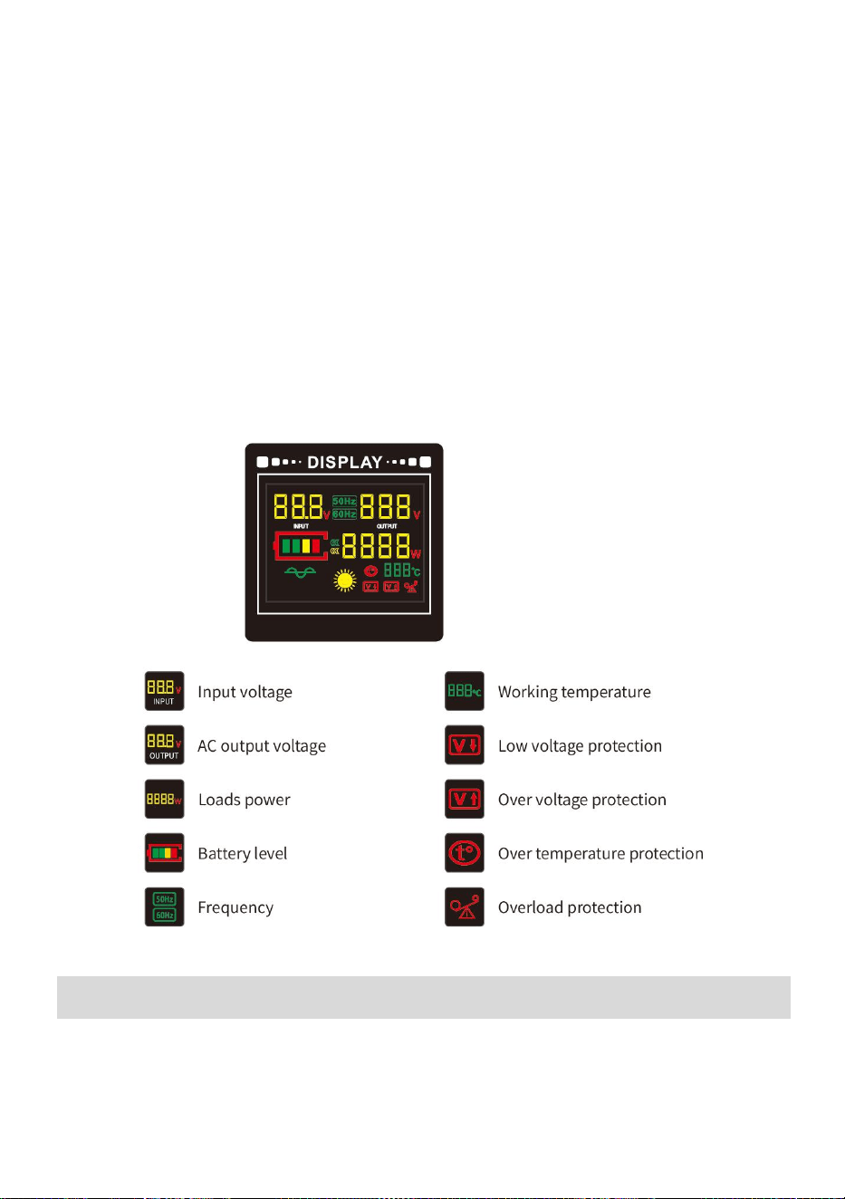
- 11 -
akumulatora jako drugi priorytet.
34. Czas przełączania z zasilania sieciowego na zasilanie akumulatorowe
i zasilanie akumulatorowe
do zasilania sieciowego jest mniejszy niż 10 ms.
35. W trybie sieciowym falownik będzie w międzyczasie ładował
akumulator przy
8-sposób ładowania krokowego.
36. Kiedy akumulator jest naładowany, zapala się czerwona dioda LED
ładowania i kiedy
akumulator jest w pełni naładowany, czerwona dioda ładowania zgaśnie
i zaświeci się cała zielona dioda LED.
Wyświetlacz LCD :( Patrz rysunek 5)
Rysunek 5
Protection mode
Charakterystyka (tryb falownika ).
Nasze falowniki posiadają doskonałe mechanizmy zabezpieczające, w tym
zabezpieczenie przed wysokim napięciem akumulatora, zabezpieczenie przed
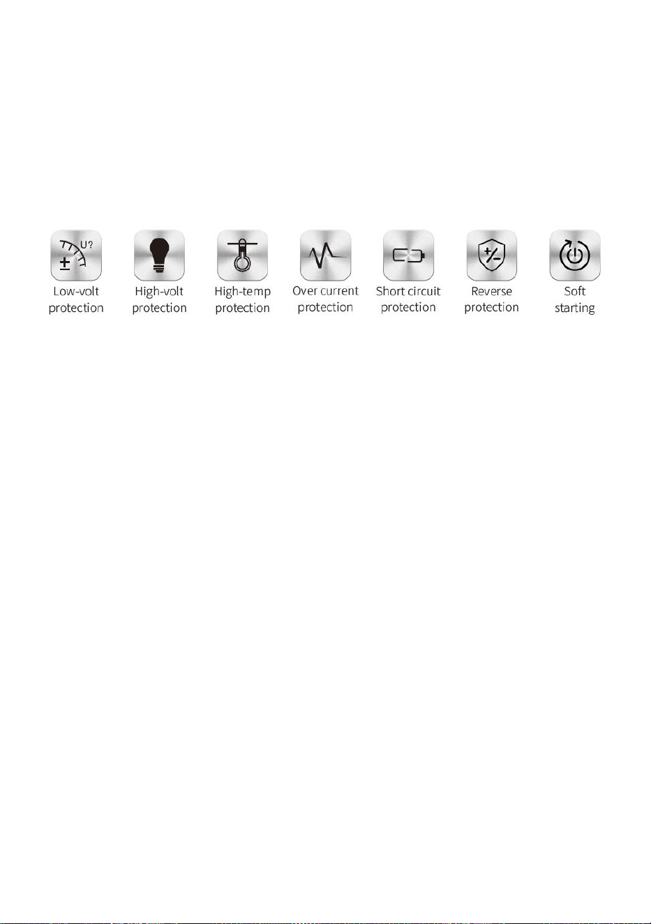
- 12 -
niskim napięciem akumulatora, zabezpieczenie przed zwarciem wyjścia,
zabezpieczenie przed przeciążeniem oraz zabezpieczenie przeciwzakłóceniowe
akumulatora i obciążenia. Miękki start falownika może stopniowo zwiększać
napięcie wyjściowe, co ma wpływ na buforowanie prądu rozruchowego podczas
uruchamiania urządzenia elektrycznego dużej mocy, poprawiając w ten sposób
obciążalność falownika. (Schemat funkcji zabezpieczającej pokazano na rysunku
6).
Rysunek 6
Co wyświetla wyświetlacz w trybie chronionym . ( Patrz rysunek 7)

- 13 -
Rysunek 7
Parametry techniczne .

- 14 -

- 15 -
FAULT INFORMATION GUIDE

- 16 -

- 17 -
WARRANTY CARD
Do naszych drogich klientów:
Dziękujemy za korzystanie z naszych falowników. Prosimy o
przeczytanie i zachowanie karty gwarancyjnej, aby zapewnić
gwarancję posprzedażową.
Klauzula gwarancyjna.
16. Wszystkie nasze produkty przeszły rygorystyczne testy przed
zapakowaniem, aby zapewnić
jakość wykonania.
17. Gwarancja na falownik od daty zakupu: 1 rok.
18. Po upływie okresu gwarancyjnego zaoferujemy usługę odpłatną
dla naszych produktów .
Nie dotyczy:
Nasze produkty nie podlegają zwrotowi ani wymianie, jeśli spełniają
następujące warunki:
26. Produkt uszkodzony w wyniku nieprawidłowej obsługi/konserwacji/
składowanie.
27. Produkty, które zostały uszkodzone w wyniku nieuprawnionego
usunięcia przez firmę
użytkownika lub szkody spowodowane przez nieautoryzowanych
konserwatorów Firmy.
28. Użytkownik nie może okazać karty gwarancyjnej ani ważnego dowodu
zakupu.
29. Karta gwarancyjna i informacje o produkcie nie zgadzają się z
gwarancją
karta została zmieniona.
30. Szkody powstałe w wyniku powodzi, pożaru, trzęsienia ziemi lub
innych kataklizmów nie są
objęte niniejszą gwarancją. W powyższych przypadkach zapewniamy

- 18 -
usługę odpłatną.
Podczas zakupu należy podać prawidłowe informacje o
użytkowniku produktu lub firmie i poprosić dystrybutora o
stemplowanie karty gwarancyjnej.
ACCESSORY INFORMATION
21.Instrukcja obsługi * 1
22.Bateria jest podłączona do przewodu * 2
23.Bezpiecznik prądowy 40A DC :
SGPC2000W-121 * 6
SGPC2500W-121 * 8
24.PRZEWÓD WTYCZKI NAPIĘCIA AC * 1
Bateria: 12 V DC Sieć zasilająca: 120 V AC 60 Hz
Producent: Shanghaimuxinmuyeyouxiangongsi
Adres : Shuangchenglu 803nong11hao1602A-1609shi, baoshanqu,
szanghaj 200000 CN.
Import do AUS: SIHAO PTY LTD, 1 ROKEVA STREETEASTWOOD NSW
2122 Australia
Import do USA: Sanven Technology Ltd., Suite 250, 9166 Anaheim Place,
Rancho Cucamonga, CA 91730

- 19 -
REP
EC
E-CrossStu GmbH
Mainzer Landstr.69, 60329 Frankfurt am Main.
REP
UK
YH CONSULTING LIMITED.
C/O YH Consulting Limited Office 147, Centurion House,
London Road, Staines-upon-Thames, Surrey, TW18 4AX


Technisch Ondersteuning en e-garantiecertificaat
www.vevor.com/support
SUMP POMP STROOMOMVORMER
HANDLEIDING
MODEL: SGPC2000W-121/SGPC2500W-121
We continue to be committed to provide you tools with competitive price.
"Save Half", "Half Price" or any other similar expressions used by us only represents an
estimate of savings you might benefit from buying certain tools with us compared to the major
top brands and does not necessarily mean to cover all categories of tools offered by us. You
are kindly reminded to verify carefully when you are placing an order with us if you are
actually saving half in comparison with the top major brands.


- 1 -
SGPC2000W-121
SGPC2500W-121
Have product questions? Need technical support? Please feel free to
contact us:
Technical Support and E-Warranty Certificate
www.vevor.com/support
NEED HELP? CONTACT US!
This is the original instruction, please read all manual instructions
carefully before operating. VEVOR reserves a clear interpretation of our
user manual. The appearance of the product shall be subject to the
product you received. Please forgive us that we won't inform you again if
there are any technology or software updates on our product.
SUMP PUMP POWER INVERTER
- 2 -
Waarschuwing-Om het risico op letsel te verminderen, moet de
gebruiker de handleiding zorgvuldig lezen.
Dit apparaat voldoet aan Deel 15 van de FCC-regels. Het gebruik is
onderworpen aan de volgende twee voorwaarden: (1) Dit apparaat
mag geen schadelijke interferentie veroorzaken, en (2) dit apparaat
moet alle ontvangen interferentie accepteren, inclusief interferentie
die een ongewenste werking kan veroorzaken.
Dit product valt onder de bepalingen van de Europese richtlijn
2012/19/EG. Het symbool met een doorgestreepte afvalcontainer
geeft aan dat het product in de Europese Unie een aparte
afvalinzameling vereist. Dit geldt voor het product en alle
accessoires die met dit symbool zijn gemarkeerd. Producten die als
zodanig gemarkeerd zijn, mogen niet bij het normale huisvuil worden
weggegooid, maar moeten naar een inzamelpunt voor recycling van
elektrische en elektronische apparaten worden gebracht
INSTRUCTIONS
Bedankt dat u voor ons product heeft gekozen. Lees deze
gebruikershandleiding aandachtig door om het product correct te
installeren en te gebruiken. en bewaar het op een veilige plaats voor
verder gebruik.
Om veilig te kunnen werken, moet de omvormer op de juiste manier
worden geïnstalleerd en gebruikt. Lees de gebruikershandleiding
zorgvuldig door voordat u deze installeert en gebruikt. Besteed speciale
aandacht aan deze waarschuwingen en waarschuwingsverklaringen in
deze handleiding, waarschuwingen over bepaalde omstandigheden en
praktijken die de omvormer kunnen beschadigen, en verklaringen die
waarschuwen voor gebruiksomstandigheden en praktijken die kunnen
leiden tot persoonlijk letsel, evenals alle voorzorgsmaatregelen voordat u
de omvormer gebruikt. omvormer.
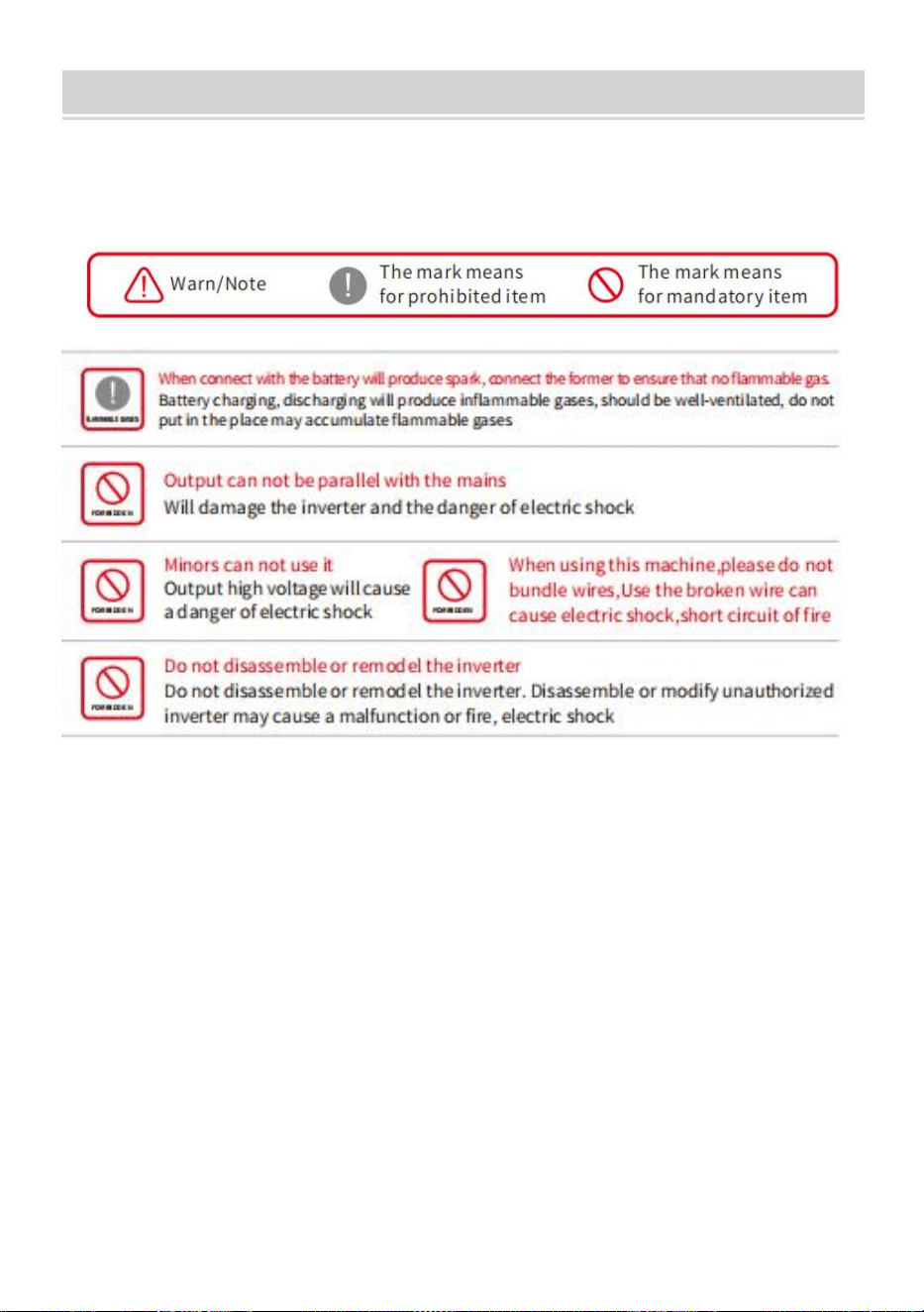
- 3 -
SAFETY NOTICE
Om te voorkomen dat u en anderen schade oplopen, verzoeken wij u
hier de volgende veiligheidsvoorschriften te vermelden. Zorg ervoor dat u
zich hieraan houdt en raadpleeg de borden met de volgende betekenis

- 4 -
- 5 -
Nominale stroom en daadwerkelijk gebruikte apparatuur:
De meeste elektrische gereedschappen, huishoudelijke apparaten en
audiovisuele apparatuur, in het vermogensbereik of veel lager, maar
wanneer ze zijn geactiveerd UPIT is beveiligd tegen overbelasting. De
omvormer zal hoogstwaarschijnlijk resistieve belastingen aandrijven en
stroombelastingen schakelen, omdat resistieve belastingen lineaire
belastingen zijn die kunnen werken, zoals elektrische fornuizen, rijstkokers,
lcd-tv's en andere apparatuur. Gedeeltelijk audiovisueel Apparatuur en
elektrisch gereedschap hebben meer vermogen nodig dan resistieve
belastingen om goed te kunnen functioneren. Asynchrone motoren, CRT
TV's, compressoren, pompen enzovoort. Ze hebben 2 tot 6 keer de
bedrijfsstroom nodig om te starten . Of het een specifieke belasting kan
uitvoeren, hangt af van de onderwerptest.
Toegepast op de volgende producten:
De normale capaciteit van dit product kan worden gebruikt voor lampen,
rijstkokers,
desktopcomputers, laptops, computermonitors, printers, televisies,
ventilatoren, mobiele telefoons, digitale producten, booreilanden,
elektrische strijkijzers, wasmachines en andere originele apparatuur
beschikbare elektriciteit.
Wanneer u een pomptype belasting gebruikt, kies er dan een met een
capaciteit
groter dan meer dan het dubbele van het laadvermogen, en controleer
nogmaals of het laadvermogen dat u wilt gebruiken minder dan één keer
het vermogen van ons product is.
INTRODUCTION OF PERFORMANCE
De omvormer is een stroomapparaat dat gelijkstroom (opslagbatterijen,
zonnecellen, windenergie) kan omzetten in wisselstroom, en de omvormer

- 6 -
maakt gebruik van hoogfrequente stroomconversietechnologie en gebruikt
een ferriettransformator in plaats van de oude, omvangrijke transformator
van siliciumstaal. Daarom zijn onze stroomomvormers lichter en kleiner
dan andere omvormers in hun soort. In de invertermodus is de
uitgangsgolfvorm een sinusgolf. ( Zie figuur 1 ).
Figuur 1: Uitgangssinusgolfvorm
1. Gebruiksomgeving.
Voor het beste gebruik plaatst u de omvormer op een vlakke
ondergrond, zoals de grond, de autovloer of een ander stevig oppervlak
waar het netsnoer van de omvormer gemakkelijk kan worden bevestigd.
De werkplek moet aan de volgende voorwaarden voldoen:
Houd het droog, zorg ervoor dat de omvormer niet in contact komt met
water of iets dergelijks
vloeistoffen, bewaar de omvormer Uit de buurt van vocht of water
houden.
Koele omgeving met een temperatuur van 0 graden Celsius Tot 50
graden
Celsius, plaats de omvormer niet naast ventilatieopeningen of andere
verwarmde voertuigen. Probeer de omvormer uit direct zonlicht te
houden.
De omringende ventilatie belemmert de omgeving niet,

- 7 -
waardoor de lucht vrij kan stromen. Leg tijdens het werken niets op de
omvormer.
De omvormer werkt niet in de buurt van brandbare of ontvlambare
materialen
Gassen .
De batterij kan niet alleen gelijkstroom leveren van 10V tot 15V (onder
een spanning van 12V
systeem), maar ook voldoende laadstroom hebben. Loodzuuraccu's
moeten volledig opgeladen zijn en een goede kwaliteit en capaciteit
hebben, of lithiumbatterijen met voldoende ontlaadstroom.
Hoogwaardige loodzuurbatterijen en lithiumbatterijen met hoge capaciteit
voldoende ontlaadstroom. Een ruwe schatting van de huidige capaciteit
van de accu is het delen van het vermogen van de belasting door tien
(12V-systeem).
Let op: Bijvoorbeeld: als het vermogen van een belasting 100W is, moet
de stroom van de batterij 100/10=10A geleverd worden, deze
handleiding bevat niet alle batterijcombinaties. De specificaties van de
batterij behoren tot andere gebieden van de technologie.
Paneelschema . ( Zie figuur 2)
Figuur 2
WITH CHARGING PANEL DESCRIPTION

- 8 -
Accu-aansluitschema ( zie figuur 3)
figuur 3
Installatie-verbindingsstappen .
Raadpleeg het bedradingsschema in Figuur 3.
37. Schakel eerst de stroom van de omvormer uit .
38. Gebruik een zwarte DC-kabel om de negatieve pool van de accu aan
te sluiten op de
zwarte aansluitkop van de omvormer.
39. Gebruik de rode DC-kabel om de anodeterminal van de batterij aan te
sluiten en
de rode paalkop van de omvormer .
40. Sluit de elektrische apparaten aan op de uitgangsaansluiting van de
omvormer.
41. Zet de inverterschakelaar aan .
42. Steek de AC-kabel in de netingang.
De omvormer kan één of meerdere accu's gebruiken, maar het beste
kunt u één of meerdere accu's gebruiken Accu's met een capaciteit van
150 Ah of meer.

- 9 -
Gebruik de kabel die bij de omvormer is verkocht om de omvormer en de
batterij aan te sluiten; De rode kabel verbindt de anodeterminal van de
batterij en het rode stigma van de omvormer. De zwarte kabel verbindt de
negatieve pool van de batterij en het zwarte stigma van de omvormer. Zorg
ervoor dat alle kabels stevig vastzitten. Ongeschikt Door de aansluiting kan
de kabel oververhit raken en het klemmenblok beschadigen, wat ook het
geval zal zijn Verkort de voedingstijd van de batterij.
Zet de aan/uit-schakelaar aan. De werkende LED van de omvormer
wordt rood wanneer de batterij volledig is opgeladen, en wanneer de
omvormer in de netinvoermodus staat, wordt de werkende LED van de
omvormer groen.
Als er een storing is, wordt op het LCD-scherm een storingspictogram
weergegeven. Vervolgens moet u controleren of de accuspanning te hoog
of te laag is en of de uitgang van de omvormer overbelast of kortgesloten
is.
Tegelijkertijd geeft het LCD-scherm ook de foutcode weer. Zoek de fout
op en controleer deze De reden staat op pagina 1 2-13 .
De DC-voeding van een 12V-omvormer kan bestaan uit één 12V-batterij
of meerdere tegengestelde 12V-batterijen om de voedingstijd te verlengen.
Opmerking: De batterijspanning die op de omvormer is aangesloten,
moet hetzelfde zijn als de DC-ingangsspanning van de omvormer, de
12V-omvormer moet bijvoorbeeld op de 12V-batterij worden aangesloten.
Zorg ervoor dat alle apparatuur is uitgeschakeld voordat u deze inschakelt.
Demonteer stappen .
31. Schakel eerst de stroomschakelaar van de omvormer uit.
32. Haal de stekker uit het stopcontact .
33. Demonteer de rode DC-kabel .
34. Demonteer de zwarte DC-kabel .
35. Het is klaar met demonteren .
Met netlader en UPS-functie .
Kenmerken van conventionele omvormers , netstroom eerste keuze om
deze altijd te beschermen, netstroom en batterij automatisch geschakeld,
continue UPS-bescherming. ( Zie figuur 4)

- 10 -
Figuur 4
Functiebeschrijving :
37. Sluit de netvoeding niet aan op de AC-uitgang van de omvormer,
anders kan dit gebeuren
vernietig de omvormer.
38. Rastermodus: Wanneer de netvoeding is aangesloten op de
AC-ingangsstekker, wordt de
Bij de AC-uitgangsaansluiting is netstroom de eerste prioriteit.
39. Batterijmodus: Wanneer de netvoeding is losgekoppeld van de
omvormer
AC-ingang, de AC-uitgangsaansluiting zal als tweede prioriteit
automatisch stroom van de batterij afgeven.
40. De schakeltijd van netstroom naar batterijvoeding en batterijvoeding
naar netstroom is minder dan 10 ms.
41. In de netmodus laadt de omvormer de accu tussentijds op
9-stap opladen manier.

- 11 -
42. Wanneer de batterij is opgeladen, brandt de rode oplaad-LED, en
wanneer
de batterij is volledig opgeladen. De rode oplaad-LED gaat uit en de
volledig groene LED gaat branden.
LCD-scherm :( Zie figuur 5)
Figuur 5
Protection mode
Kenmerken (Omvormermodus ).
Onze omvormers beschikken over perfecte beschermingsmechanismen,
waaronder bescherming tegen hoge spanning van de batterij, bescherming tegen
lage spanning van de batterij, bescherming tegen kortsluiting bij de uitgang,
bescherming tegen overbelasting en bescherming tegen interferentie van de
batterij en de belasting. De zachte start van de omvormer kan de
uitgangsspanning geleidelijk verhogen, wat tot gevolg heeft dat de
inschakelstroom wordt gebufferd wanneer het krachtige elektrische apparaat
wordt gestart, waardoor het laadvermogen van de omvormer wordt verbeterd.
(Een schematisch diagram van de beveiligingsfunctie wordt getoond in figuur 6).

- 12 -
Figuur 6
Wat het display weergeeft in de beschermde modus . ( Zie afbeelding 7)
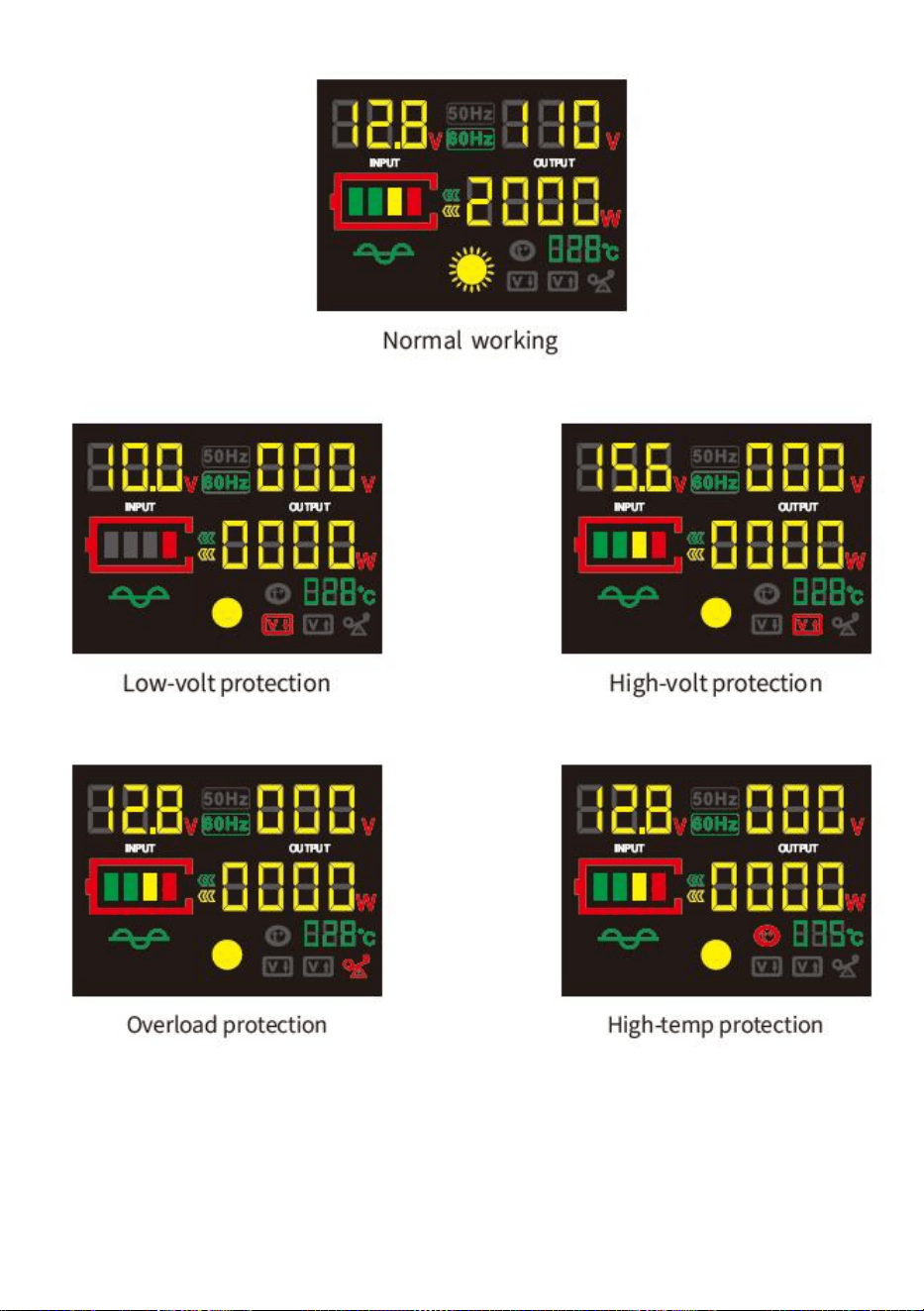
- 13 -
Figuur 7
Technische parameters .

- 14 -

- 15 -
FAULT INFORMATION GUIDE
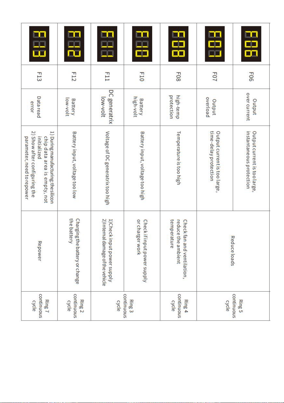
- 16 -

- 17 -
WARRANTY CARD
Aan onze lieve klanten:
Bedankt voor het gebruik van onze omvormers. Lees en bewaar de
garantiekaart om onze after-sales garantie te garanderen.
Garantieclausule.
19. Al onze producten hebben vóór het verpakken strenge tests doorstaan
om de kwaliteit te garanderen
kwaliteit en prestaties.
20. Garantie op omvormer vanaf de aankoopdatum: 1 jaar.
21. Wanneer de garantieperiode is verstreken, bieden wij compenserende
service
voor onze producten .
Niet toepasbaar:
Onze producten zijn niet restitueerbaar of omruilbaar als ze onder de
volgende omstandigheden vallen:
31. Het product is beschadigd door onjuiste bediening/onderhoud/
opslag.
32. Producten die beschadigd zijn door ongeoorloofde verwijdering door
de
gebruiker of schade veroorzaakt door niet-geautoriseerde
onderhoudspersoneel van het bedrijf.
33. De gebruiker kan de garantiekaart of een geldig aankoopbewijs niet
aanbieden.
34. Garantiekaart en productinformatie komen niet overeen met de
garantie
kaart is gewijzigd.
35. Schade veroorzaakt door overstromingen, brand, aardbevingen of
andere rampen niet
gedekt door deze garantie. In bovengenoemde gevallen bieden wij een

- 18 -
compenserende service.
Vul bij aankoop de juiste productgebruikers- of bedrijfsinformatie
in en vraag dit aan de distributeur. Stempel de garantiekaart.
ACCESSORY INFORMATION
25.Gebruiksaanwijzing * 1
26.De batterij is aangesloten op de draad * 2
27.40A DC-stroomzekering :
SGPC2000W-121*6
SGPC2500W-121*8
28.AC-SPANNINGSSTEKKERDRAAD * 1
Batterij: 12V DC Elektriciteitsnet: 120VAC 60HZ
Fabrikant: Shanghaimuxinmuyeyouxiangongsi
Adres : Shuangchenglu 803nong11hao1602A-1609shi, baoshanqu,
shanghai 200000 CN.
Geïmporteerd naar AUS: SIHAO PTY LTD, 1 ROKEVA
STREETEASTWOOD NSW 2122 Australië
Geïmporteerd naar de VS: Sanven Technology Ltd., Suite 250, 9166
Anaheim Place, Rancho Cucamonga, CA 91730

- 19 -
REP
EC
E-CrossStu GmbH
Mainzer Landstr.69, 60329 Frankfurt am Main.
REP
UK
YH CONSULTING LIMITED.
C/O YH Consulting Limited Office 147, Centurion House,
London Road, Staines-upon-Thames, Surrey, TW18 4AX


Teknisk Support och e-garanticertifikat
www.vevor.com/support
SUMPPUMPS STRÖMRIKTARE
BRUKSANVISNING
MODELL: SGPC2000W-121/SGPC2500W-121
We continue to be committed to provide you tools with competitive price.
"Save Half", "Half Price" or any other similar expressions used by us only represents an
estimate of savings you might benefit from buying certain tools with us compared to the major
top brands and does not necessarily mean to cover all categories of tools offered by us. You
are kindly reminded to verify carefully when you are placing an order with us if you are
actually saving half in comparison with the top major brands.


- 1 -
SGPC2000W-121
SGPC2500W-121
Have product questions? Need technical support? Please feel free to
contact us:
Technical Support and E-Warranty Certificate
www.vevor.com/support
NEED HELP? CONTACT US!
This is the original instruction, please read all manual instructions
carefully before operating. VEVOR reserves a clear interpretation of our
user manual. The appearance of the product shall be subject to the
product you received. Please forgive us that we won't inform you again if
there are any technology or software updates on our product.
SUMP PUMP POWER INVERTER

- 2 -
Varning - För att minska risken för skada måste användaren läsa
instruktionerna noggrant.
Denna enhet uppfyller del 15 av FCC-reglerna. Driften är föremål för
följande två villkor: (1) Den här enheten får inte orsaka skadliga
störningar och (2) den här enheten måste acceptera alla mottagna
störningar, inklusive störningar som kan orsaka oönskad funktion.
Denna produkt omfattas av bestämmelserna i det europeiska
direktivet 2012/19/EC. Symbolen som visar en soptunna korsad
anger att produkten kräver separat sophämtning i EU. Detta gäller för
produkten och alla tillbehör märkta med denna symbol. Produkter
märkta som sådana får inte slängas tillsammans med vanligt
hushållsavfall, utan måste lämnas till en insamlingsplats för
återvinning av elektriska och elektroniska apparater
INSTRUCTIONS
Tack för att du valde vår produkt, läs denna bruksanvisning noggrant för
att installera och använda produkten på rätt sätt. och förvara en säker plats
för vidare användning.
Växelriktaren måste installeras korrekt och användas på rätt sätt för att
den ska fungera säkert. Läs bruksanvisningen noggrant innan du
installerar och använder den. Var särskilt uppmärksam på dessa varningar
och varningsmeddelanden i den här handboken, varningar om vissa
förhållanden och metoder som kan skada omriktaren och uttalanden som
varnar för användningsförhållanden och metoder som kan resultera i
personskada, samt alla försiktighetsåtgärder innan du använder inverter.
SAFETY NOTICE
För att undvika att skada dig och andra, vänligen lista följande
säkerhetsmeddelanden här, se till att följa och hänvisa till skyltarna med
följande betydelser

- 3 -
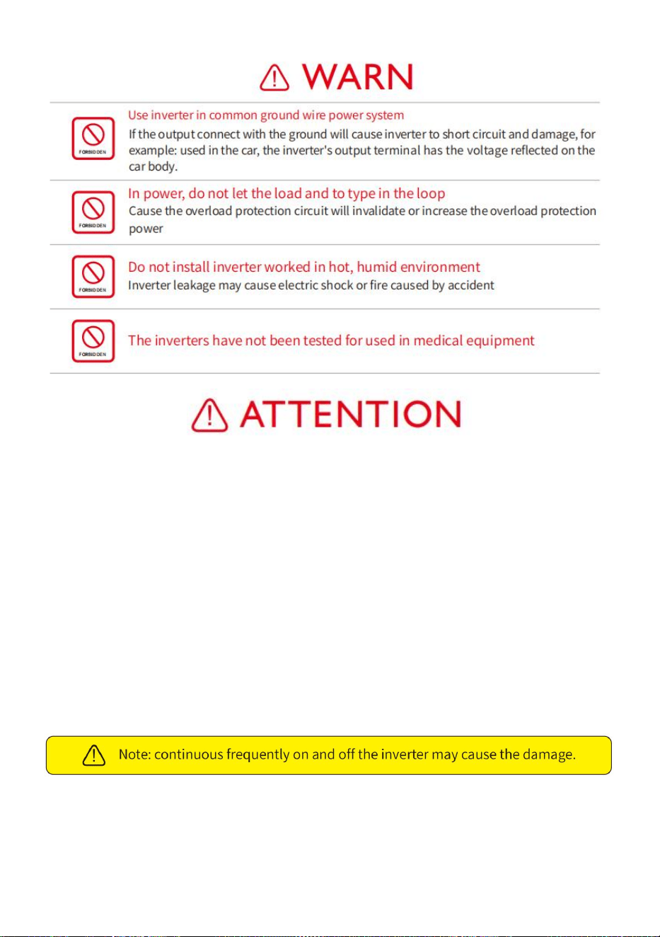
- 4 -
Märkström och utrustning som faktiskt används:
De flesta elverktyg, hushållsapparater och audiovisuell utrustning, i
märkeffektområdet eller mycket lägre, men när de är aktiverade UPIT
kommer att vara överbelastningsskyddad. Det är mest sannolikt att
växelriktaren driver resistiva belastningar och växlar effektbelastningar,
eftersom resistiva belastningar är linjära belastningar som kan fungera,
såsom elektriska spisar, riskokare, LCD-TV och annan utrustning. Delvis
audiovisuellt Utrustning och elverktyg kräver mer kraft än resistiva
belastningar för att fungera korrekt, Asynkronmotorer, CRT TV-apparater,
kompressorer, pumpar och så vidare. De behöver 2 till 6 gånger av
driftströmmen för att starta. Huruvida den kan köra en specifik belastning
beror på ämnestestet.
Tillämpas på följande produkter:
Den normala kapaciteten för denna produkt kan användas för lampor,
riskokare,
stationära datorer, bärbara datorer, datorskärmar, skrivare, tv-apparater,
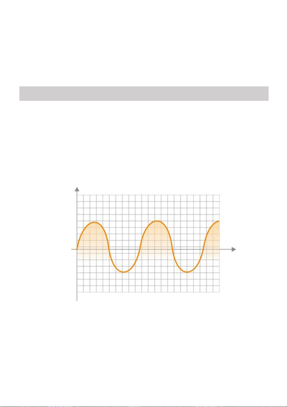
- 5 -
fläktar, mobiltelefoner, digitala produkter, borriggar, elektriska strykjärn,
tvättmaskiner och annan originalutrustning tillgänglig el.
När du använder en pumptyp av last, välj en som har en kapacitet
större än mer än dubbelt så mycket lastkapacitet, och dubbelkolla att
lasteffekten du vill använda är mindre än en gång vår produkts effekt.
INTRODUCTION OF PERFORMANCE
Växelriktaren är en kraftenhet som kan omvandla likström
(lagringsbatterier, solceller, vindenergi) till växelström, och växelriktaren
använder högfrekvent kraftomvandlingsteknik och använder en
ferrittransformator istället för den gamla skrymmande transformatorn av
kiselstål. Det är därför våra strömriktare är lättare och mindre än andra
växelriktare av sitt slag. I inverterläge är den utgående vågformen en
sinusvåg. ( Se figur 1 ).
Figur 1: Utmatad sinusvågform
1. Använda miljön.
För bästa användning, placera växelriktaren på en plan yta, såsom
marken, bilgolvet eller andra fasta ytor där växelriktarens strömkabel lätt
kan fästas. Arbetsplatsen bör uppfylla följande villkor:
Håll den torr, låt inte växelriktaren komma i kontakt med vatten eller

- 6 -
annat
vätskor, behåll växelriktaren Håll borta från fukt eller vatten.
Sval miljö med en temperatur på 0 grader Celsius Till 50 grader
Celsius, placera inte växelriktaren bredvid ventiler eller andra
uppvärmda fordon. Försök att hålla växelriktaren borta från direkt solljus.
Den omgivande ventilationen hindrar inte det omgivande området,
hålla luften flödande fritt. Placera ingenting på växelriktaren när du
arbetar.
Växelriktaren fungerar inte runt brännbart material eller brandfarligt
Gaser .
Batteriet kan inte bara ge likström från 10V till 15V (under en 12V
system), men också ha tillräcklig belastningsström. Blybatterier bör vara
fulladdade och ha god kvalitet och kapacitet eller litiumbatterier med
tillräcklig urladdningsström.
Högkvalitativa blybatterier och litiumbatterier med hög kapacitet har
tillräcklig urladdningsström. En grov uppskattning av batteriets
nuvarande kapacitet är att dela belastningens effekt med tio
(12V-system).
Obs: Till exempel: om effekten av en belastning är 100W måste batteriets
ström100/10=10A tillföras, denna manual inkluderar inte alla
batterikombinationer. Batteriets specifikationer tillhör andra
teknikområden.
Panelschema .( Se figur 2)
WITH CHARGING PANEL DESCRIPTION
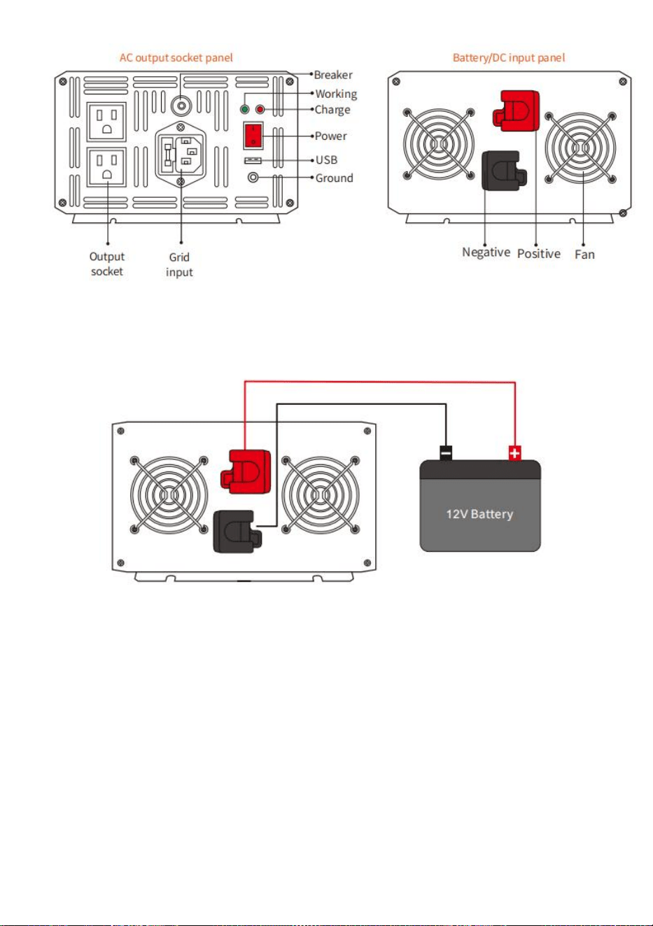
- 7 -
figur 2
Batterianslutningsschema .( Se bild 3)
Figur 3
Installationsanslutningssteg .
Se kopplingsschemat i figur 3.
43. Stäng först och främst av strömriktaren .
44. Använd en svart DC-kabel för att ansluta batteriets minuspol till
växelriktarens svarta bindande posthuvud.
45. Använd den röda DC-kabeln för att ansluta batteriets anodpol och
växelriktarens röda stolphuvud .
46. Anslut de elektriska enheterna till växelriktarens utgång.
47. Slå på inverterbrytaren .
48. Sätt in AC-kabeln i nätingången.

- 8 -
Växelriktaren kan använda ett eller flera batterier, men det är bäst att
använda ett eller flera batterier Batterier med en kapacitet på 150AH eller
högre.
Använd kabeln som säljs med växelriktaren för att ansluta växelriktaren
och batteriet; Den röda kabeln ansluter anodpolen på batteriet och
växelriktarens röda stigmatisering, den svarta kabeln ansluter batteriets
minuspol och den svarta märkningen på batteriet inverter. Se till att alla
kablar är ordentligt fastsatta. Olämplig Anslutningen kan göra att kabeln
överhettas och skada kopplingsplinten, och det kommer den också att göra
Förkorta batteriets strömförsörjningstid.
Slå på strömbrytaren, växelriktarens arbets-LED blir röd när batteriet är
fulladdat, och när växelriktaren är i nätingångsläge blir växelriktarens
arbets-LED grön.
Om det finns något fel kommer LCD-displayen att visa en felikon, och
sedan måste du kontrollera om batterispänningen är för hög eller för låg,
och kontrollera om växelriktarens utgång är överbelastad eller kortsluten.
Samtidigt visar LCD-skärmen även felkoden, ta reda på och kontrollera
felet Anledningen finns på sidan 1 2-13 .
DC-strömförsörjningen för en 12V-växelriktare kan vara ett 12V-batteri
eller flera motsatta 12V-batterier för att öka strömförsörjningstiden.
Obs: Batterispänningen som är ansluten till växelriktaren måste vara
densamma som växelriktarens DC-ingångsspänning, t.ex. bör
12V-växelriktaren anslutas till 12V-batteriet, och se till att all utrustning är
avstängd innan du slår på den.
Demontera steg .
36. Stäng först av växelriktarens strömbrytare.
37. Koppla ur strömkontakten .
38. Demontera den röda DC-kabeln .
39. Demontera den svarta DC-kabeln .
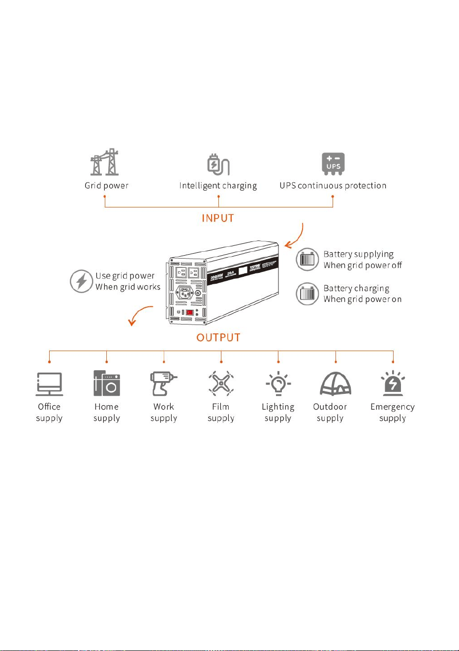
- 9 -
40. Det är klart att demontera .
Med nätladdare och UPS-funktion .
Egenskaper för konventionell växelriktare , Nätström förstahandsval för
att skydda den drivs hela tiden, nätström och batteri byts automatiskt, UPS
kontinuerligt skydd.( Se figur 4)
Figur 4
Funktionsbeskrivning :
43. Anslut inte elnätet till växelriktarens AC-utgång, annars kan det hända
förstör växelriktaren.
44. Grid Mode: När nätströmmen är ansluten till AC-ingången,
AC-utgångsuttaget sätter elnätet som första prioritet.
45. Batteriläge: När nätströmmen är bortkopplad från växelriktaren
AC-ingång, kommer AC-utgången automatiskt att mata ut ström från
batteriet som en andra prioritet.
46. Växlingstiden från elnät till batterikraft och batterikraft

- 10 -
till elnätet är mindre än 10ms.
47. I grid-läge kommer växelriktaren att ladda batteriet under tiden, med
10-stegladdningssätt.
48. När batteriet är laddat tänds den röda laddningslampan och när
batteriet är fulladdat, den röda lysdioden för laddning släcks och den
gröna lysdioden lyser.
LCD-skärm :( Se bild 5)
Figur 5
Protection mode
Egenskaper (växelriktarläge ).
Våra växelriktare har perfekta skyddsmekanismer, inklusive
batterihögspänningsskydd, batterilågspänningsskydd, utgångskortslutningsskydd,
överbelastningsskydd och batteri- och belastningsskydd mot störningar.
Mjukstarten av växelriktaren kan gradvis öka utspänningen, vilket har effekten att
buffra inkopplingsströmmen när den elektriska apparaten med hög effekt startas,
och därigenom förbättra växelriktarens belastningskapacitet. (Ett schematiskt
diagram över skyddsfunktionen visas i figur 6).

- 11 -
Bild 6
Vad displayen visar i skyddat läge .( Se bild 7)

- 12 -
Figur 7
Tekniska parametrar .

- 13 -

- 14 -
FAULT INFORMATION GUIDE

- 15 -

- 16 -
WARRANTY CARD
Till våra kära kunder:
Tack för att du använder våra växelriktare, läs och behåll
garantikortet för att säkerställa vår efterförsäljningsgaranti.
Garantiklausul.
22. Alla våra produkter hade genomgått stränga tester innan de packades
för att säkerställa
kvalitet & prestanda.
23. Invertergaranti från inköpsdatum: 1 år.
24. När garantitiden har löpt ut kommer vi att erbjuda ersättningsbar
service
för våra produkter .
Inte tillämpbar:
Våra produkter är varken återbetalningsbara eller utbytbara om de hör till
följande omständigheter:
36. Produkten skadad av användarens felaktiga användning/underhåll/
lagring.
37. Produkter som har skadats på grund av obehörig borttagning av
användare eller skada orsakad av icke-auktoriserade underhållare av
företaget.
38. Användaren kan inte erbjuda garantikortet eller giltigt köpkvitto.
39. Garantikort och produktinformation stämmer inte överens eller
garantin
kortet har ändrats.
40. Skador orsakade av översvämning, brand, jordbävning eller andra
katastrofer är det inte
täcks av denna garanti. I ovanstående fall kommer vi att tillhandahålla en
ersättningsgill tjänst.
Vänligen fyll i rätt produktanvändare eller företagsinformation vid

- 17 -
köp och fråga distributören Stämpla garantikortet.
ACCESSORY INFORMATION
29.Bruksanvisning * 1
30.Batteriet är anslutet till kabeln * 2
31.40A DC-strömsäkring :
SGPC2000W-121 * 6
SGPC2500W-121 * 8
32.AC-SPÄNNINGSKONTAKTKABEL * 1
Batteri:12V DC Elnät:120VAC 60HZ
Tillverkare: Shanghaimuxinmuyeyouxiangongsi
Adress : Shuangchenglu 803nong11hao1602A-1609shi, baoshanqu,
shanghai 200000 CN.
Importerad till AUS: SIHAO PTY LTD, 1 ROKEVA STREETEASTWOOD
NSW 2122 Australien
Importerad till USA: Sanven Technology Ltd., Suite 250, 9166 Anaheim
Place, Rancho Cucamonga, CA 91730
REP
EC
E-CrossStu GmbH
Mainzer Landstr.69, 60329 Frankfurt am Main.
REP
UK
YH CONSULTING LIMITED.
C/O YH Consulting Limited Office 147, Centurion House,
London Road, Staines-upon-Thames, Surrey, TW18 4AX

- 18 -