
INSTRUCTION MANUAL
Cordless Compact Router
18~20V
Read before use.
IMPORTANT: Read Before Using
左上角加
logo和
slogan,电
池去掉,底部
加Made in
China。说明
书重新排版
INSTRUCTION MANUAL
Cordless Compact Router
18~20V
Read before use.
IMPORTANT: Read Before Using
左上角加
logo和
slogan,电
池去掉,底部
加Made in
China。说明
书重新排版
INSTRUCTION MANUAL
Cordless Compact Router
18~20V
Read before use.
IMPORTANT: Read Before Using
左上角加
logo和
slogan,电
池去掉,底部
加Made in
China。说明
书重新排版
INSTRUCTION MANUAL
Cordless Compact Router
18~20V
Read before use.
IMPORTANT: Read Before Using
左上角加
logo和
slogan,电
池去掉,底部
加Made in
China。说明
书重新排版
YOUR ULTIMATE POWER TOOL PARTNER
MADE IN CHINA
INSTRUCTION MANUAL
Cordless Compact Router
18~20V
Read before use.
IMPORTANT: Read Before Using
左上角加
logo和
slogan,电
池去掉,底部
加Made in
China。说明
书重新排版
首页:mellif
logo+slogan
User Manual
产品标题
CORDLESS EDGER
Made in China
www.mellif-tools.com
Read Carefully before Use
CORDLESS EDGER
User Manual
www.mellif-tools.com
Read Carefully before Use
4
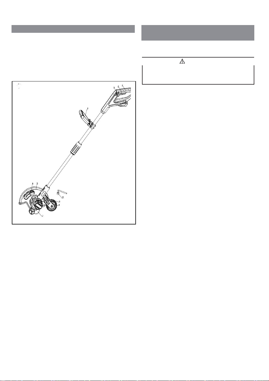
1 DESCRIPTION
1.1 PURPOSE
This edger is used to trim and cut around the edge of
driveways, side walks and more. The edger is not meant to be
used to cut hedges, shrubs, bushes, or flowers.
OVERVIEW
2 IMPORTANT SAFETY
INSTRUCTIONS
READ ALL INSTRUCTIONS BEFORE USING (THIS
POWER TOOL)
1
Rear handle
2
Trigger
3
Lock-out lever
4
Auxiliary handler
5
Guard
6
Depth adjustment knob
7
Blade
8
Wheel adjustment
frame
9
Wheel
10
Wrench
11
Metal rod
• Use only identical manufacturer’s replacement parts and
accessories. Use of any other parts may create a hazard or
cause product damage.
• Always wear safety glasses with side shields marked to
comply with ANSI Z87.1. Everyday glasses have only
impact resistant lenses. They are NOT safety glasses.
Following this rule will reduce the risk of eye injury. Use
face mask if operating in dusty work spaces.
• Avoid Dangerous Environment – Don’t expose power
tools to damp or wet conditions. Water entering a power
tool will increase the risk of electric shock.
• Don’t use in rain.
• Keep all bystanders, children, and pets at least 50 ft.
away.
• Dress Properly – Do not wear loose clothing or jewelry.
They can be caught in moving parts. Use of rubber gloves
and substantial footwear is recommended when working
outdoors. Wear protective hair covering to contain long
hair.
• Use right Appliance. Do not use appliance for any job
except that for which it is intended.
• Avoid Unintentional Starting – Don’t carry appliance
with finger on switch. Be sure switch is off when battery
plugging in.
• Don’t Force Appliance – It will do the job better and with
less likelihood of a risk of injury at the rate for which it
was designed.
• Don’t overreach – Keep proper footing and balance at all
times.
• Stay alert – Watch what you are doing. Use common
sense. Do not operate this unit when you are tired, ill or
under the influence of alcohol, drugs or medication.
• Always store idle power tools indoors – When not in use,
power tools should be stored indoors in a dry and high or
locked-up place, out of reach of children.
• Maintain Appliance With Care – Replace string head if
cracked, chipped, or damaged in any way. Be sure the
string head is properly installed and securely fastened.
Keep cutting edge sharp and clean for best performance
and to reduce the risk of injury. Follow instructions for
lubricating and changing accessories. Inspect appliance
cord periodically, and if damaged, have it repaired by an
authorized service facility. Inspect extension cords
periodically and replace if damaged. Keep handles dry,
clean, and free from oil and grease. Failure to do so can
cause serious injury.
Read and understand all instructions before using this
product. Failure to follow all instructions listed below may
result in electric shock, fire, and/or serious personal injury.
WARNING
INSTRUCTION MANUAL
Cordless Compact Router
18~20V
Read before use.
IMPORTANT: Read Before Using
左上角加
logo和
slogan,电
池去掉,底部
加Made in
China。说明
书重新排版
INSTRUCTION MANUAL
Cordless Compact Router
18~20V
Read before use.
IMPORTANT: Read Before Using
左上角加
logo和
slogan,电
池去掉,底部
加Made in
China。说明
书重新排版
INSTRUCTION MANUAL
Cordless Compact Router
18~20V
Read before use.
IMPORTANT: Read Before Using
左上角加
logo和
slogan,电
池去掉,底部
加Made in
China。说明
书重新排版
INSTRUCTION MANUAL
Cordless Compact Router
18~20V
Read before use.
IMPORTANT: Read Before Using
左上角加
logo和
slogan,电
池去掉,底部
加Made in
China。说明
书重新排版
首页:mellif
logo+slogan
User Manual
产品标题
CORDLESS EDGER
Made in China
www.mellif-tools.com
Read Carefully before Use
5
• Check damaged parts before using the appliance, a guard
or other part that is damaged should be carefully checked
to determine that it will operate properly and perform its
intended function. Check for alignment of moving parts,
binding of moving parts, breakage of parts, damaged
mountings, and any other condition that may affect its
operation. A guard or other part that is damaged should
be properly repaired or replaced by an authorized service
center unless indicated elsewhere in this manual.
• Do not charge appliance in rain, or in wet locations.
• Remove or disconnect battery before servicing, cleaning
or removing material from the gardening appliance.
• Use appliances only with specifically designated battery
packs. Use of any other battery packs may create a risk of
injury and fire.
• Have servicing performed by a qualified repair person
using only identical replacement parts. This will ensure
that the safety of the product is maintained.
• Keep guards in place and in working order.
• Keep hands and feet away from cutting area.
• Keep blades sharp.
The recommended ambient temperature range:
Item
Temperature
Edger storage temperature
range
32°F (0°C) - 113°F (45°C)
Edger operation temperature
range
32°F (0°C) - 113°F (45°C)
SAVE THESE INSTRUCTIONS
3 SYMBOLS ON THE MACHINE
Some of the following symbols can be used on this machine.
Please study them and learn their definition. Proper
interpretation of these symbols will let you operate the tool
better and safer.
Symbol
Explanation
V
Voltage
A
Current
Hz
Frequency (cycles per second)
W
Power
min
Time
/min
Revolutions, strokes, surface speed, or-
bits etc., per minute
Direct current
Precautions that involve your safety.
Read and understand all instructions be-
fore you operate the machine, and follow
all warnings and safety instructions.
Always wear safety glasses with side
shields marked to comply with ANSI
Z87.1 when you operate this machine.
加一个
保护眼
镜标志
1
5
• Check damaged parts before using the appliance, a guard
or other part that is damaged should be carefully checked
to determine that it will operate properly and perform its
intended function. Check for alignment of moving parts,
binding of moving parts, breakage of parts, damaged
mountings, and any other condition that may affect its
operation. A guard or other part that is damaged should
be properly repaired or replaced by an authorized service
center unless indicated elsewhere in this manual.
• Do not charge appliance in rain, or in wet locations.
• Remove or disconnect battery before servicing, cleaning
or removing material from the gardening appliance.
• Use appliances only with specifically designated battery
packs. Use of any other battery packs may create a risk of
injury and fire.
• Have servicing performed by a qualified repair person
using only identical replacement parts. This will ensure
that the safety of the product is maintained.
• Keep guards in place and in working order.
• Keep hands and feet away from cutting area.
• Keep blades sharp.
The recommended ambient temperature range:
Item Temperature
Edger storage temperature
range
32°F (0°C) - 113°F (45°C)
Edger operation temperature
range
32°F (0°C) - 113°F (45°C)
SAVE THESE INSTRUCTIONS
3 SYMBOLS ON THE MACHINE
Some of the following symbols can be used on this machine.
Please study them and learn their definition. Proper
interpretation of these symbols will let you operate the tool
better and safer.
Symbol Explanation
V Voltage
A Current
Hz
Frequency (cycles per second)
W
Power
min Time
/min
Revolutions, strokes, surface speed, or-
bits etc., per minute
Direct current
Precautions that involve your safety.
Read and understand all instructions be-
fore you operate the machine, and follow
all warnings and safety instructions.
Always wear safety glasses with side
shields marked to comply with ANSI
Z87.1 when you operate this machine.
加一个
保护眼
镜标志
首页:mellif
logo+slogan
User Manual
产品标题
CORDLESS EDGER
Made in China
www.mellif-tools.com
Read Carefully before Use
5
• Check damaged parts before using the appliance, a guard
or other part that is damaged should be carefully checked
to determine that it will operate properly and perform its
intended function. Check for alignment of moving parts,
binding of moving parts, breakage of parts, damaged
mountings, and any other condition that may affect its
operation. A guard or other part that is damaged should
be properly repaired or replaced by an authorized service
center unless indicated elsewhere in this manual.
• Do not charge appliance in rain, or in wet locations.
• Remove or disconnect battery before servicing, cleaning
or removing material from the gardening appliance.
• Use appliances only with specifically designated battery
packs. Use of any other battery packs may create a risk of
injury and fire.
• Have servicing performed by a qualified repair person
using only identical replacement parts. This will ensure
that the safety of the product is maintained.
• Keep guards in place and in working order.
• Keep hands and feet away from cutting area.
• Keep blades sharp.
The recommended ambient temperature range:
Item Temperature
Edger storage temperature
range
32°F (0°C) - 113°F (45°C)
Edger operation temperature
range
32°F (0°C) - 113°F (45°C)
SAVE THESE INSTRUCTIONS
3 SYMBOLS ON THE MACHINE
Some of the following symbols can be used on this machine.
Please study them and learn their definition. Proper
interpretation of these symbols will let you operate the tool
better and safer.
Symbol Explanation
V Voltage
A Current
Hz
Frequency (cycles per second)
W
Power
min Time
/min
Revolutions, strokes, surface speed, or-
bits etc., per minute
Direct current
Precautions that involve your safety.
Read and understand all instructions be-
fore you operate the machine, and follow
all warnings and safety instructions.
Always wear safety glasses with side
shields marked to comply with ANSI
Z87.1 when you operate this machine.
加一个
保护眼
镜标志
5
• Check damaged parts before using the appliance, a guard
or other part that is damaged should be carefully checked
to determine that it will operate properly and perform its
intended function. Check for alignment of moving parts,
binding of moving parts, breakage of parts, damaged
mountings, and any other condition that may affect its
operation. A guard or other part that is damaged should
be properly repaired or replaced by an authorized service
center unless indicated elsewhere in this manual.
• Do not charge appliance in rain, or in wet locations.
• Remove or disconnect battery before servicing, cleaning
or removing material from the gardening appliance.
• Use appliances only with specifically designated battery
packs. Use of any other battery packs may create a risk of
injury and fire.
• Have servicing performed by a qualified repair person
using only identical replacement parts. This will ensure
that the safety of the product is maintained.
• Keep guards in place and in working order.
• Keep hands and feet away from cutting area.
• Keep blades sharp.
The recommended ambient temperature range:
Item
Temperature
Edger storage temperature
range
32°F (0°C) - 113°F (45°C)
Edger operation temperature
range
32°F (0°C) - 113°F (45°C)
SAVE THESE INSTRUCTIONS
3 SYMBOLS ON THE MACHINE
Some of the following symbols can be used on this machine.
Please study them and learn their definition. Proper
interpretation of these symbols will let you operate the tool
better and safer.
Symbol
Explanation
V
Voltage
A
Current
Hz
Frequency (cycles per second)
W
Power
min
Time
/min
Revolutions, strokes, surface speed, or-
bits etc., per minute
Direct current
Precautions that involve your safety.
Read and understand all instructions be-
fore you operate the machine, and follow
all warnings and safety instructions.
Always wear safety glasses with side
shields marked to comply with ANSI
Z87.1 when you operate this machine.
加一个
保护眼
镜标志
6
Symbol
Explanation
Do not expose the machine to rain or
moist conditions.
Keep all bystanders at least 15m away.
Thrown objects can ricochet and result in
personal injury or property damage.
Danger - Keep hands and feet away from
blade.
4 RISK LEVELS
The following signal words and meanings are intended to
explain the levels of risk associated with this product.
SYM-
BOL
SIGNAL
MEANING
DANGER
Indicates an imminently haz-
ardous situation, which, if not
avoided, will result in death
or serious injury.
WARNING
Indicates a potentially hazard-
ous situation, which, if not
avoided, could result in death
or serious injury.
CAUTION
Indicates a potentially hazard-
ous situation, which, if not
avoided, may result in minor
or moderate injury.
CAUTION
(Without Safety Alert Sym-
bol) Indicates a situation that
may result in property dam-
age.
7
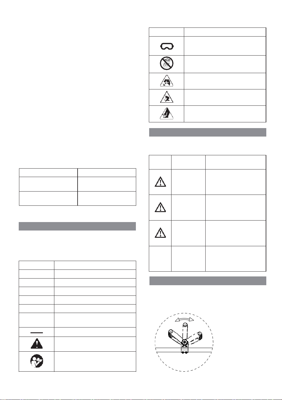
5 INSTALLATION
8.3 ASSEMBLE THE SHAFT
1. Turn the lower shaft towards the upper shaft.
8.1 ATTACH THE AUXILIARY
HANDLE
1. Attach the auxiliary handle (4) on the shaft.
2. Set the auxiliary handle in the most comfortable in use
position.
3. Tighten the knob.
5
2. Tighten the shaft .
8.4 INSTALL THE BATTERY PACK
.
1. Push the battery pack into the battery compartment until
the battery pack locks into place.
2. When you hear a click, the battery pack is installed.
7
5 INSTALLATION
8.3 ASSEMBLE THE SHAFT
1. Turn the lower shaft towards the upper shaft.
8.1 ATTACH THE AUXILIARY
HANDLE
1. Attach the auxiliary handle (4) on the shaft.
2. Set the auxiliary handle in the most comfortable in use
position.
3. Tighten the knob.
5
2. Tighten the shaft .
8.4 INSTALL THE BATTERY PACK
.
1. Push the battery pack into the battery compartment until
the battery pack locks into place.
2. When you hear a click, the battery pack is installed.
6
Symbol
Explanation
Do not expose the machine to rain or
moist conditions.
Keep all bystanders at least 15m away.
Thrown objects can ricochet and result in
personal injury or property damage.
Danger - Keep hands and feet away from
blade.
4 RISK LEVELS
The following signal words and meanings are intended to
explain the levels of risk associated with this product.
SYM-
BOL
SIGNAL MEANING
DANGER
Indicates an imminently haz-
ardous situation, which, if not
avoided, will result in death
or serious injury.
WARNING
Indicates a potentially hazard-
ous situation, which, if not
avoided, could result in death
or serious injury.
CAUTION
Indicates a potentially hazard-
ous
situation, which, if not
avoided, may result in minor
or moderate injury.
CAUTION
(Without Safety Alert Sym-
bol) Indicates a situation that
may result in property dam-
age.
7
5 INSTALLATION
8.3 ASSEMBLE THE SHAFT
1. Turn the lower shaft towards the upper shaft.
8.1 ATTACH THE AUXILIARY
HANDLE
1. Attach the auxiliary handle (4) on the shaft.
2. Set the auxiliary handle in the most comfortable in use
position.
3. Tighten the knob.
5
2. Tighten the shaft .
8.4 INSTALL THE BATTERY PACK
.
1. Push the battery pack into the battery compartment until
the battery pack locks into place.
2. When you hear a click, the battery pack is installed.
5.1
2
6
Symbol
Explanation
Do not expose the machine to rain or
moist conditions.
Keep all bystanders at least 15m away.
Thrown objects can ricochet and result in
personal injury or property damage.
Danger - Keep hands and feet away from
blade.
4 RISK LEVELS
The following signal words and meanings are intended to
explain the levels of risk associated with this product.
SYM-
BOL
SIGNAL
MEANING
DANGER
Indicates an imminently haz-
ardous situation, which, if not
avoided, will result in death
or serious injury.
WARNING
Indicates a potentially hazard-
ous situation, which, if not
avoided, could result in death
or serious injury.
CAUTION
Indicates a potentially hazard-
ous situation, which, if not
avoided, may result in minor
or moderate injury.
CAUTION
(Without Safety Alert Sym-
bol) Indicates a situation that
may result in property dam-
age.
7
5 INSTALLATION
8.3 ASSEMBLE THE SHAFT
1. Turn the lower shaft towards the upper shaft.
8.1 ATTACH THE AUXILIARY
HANDLE
1. Attach the auxiliary handle (4) on the shaft.
2. Set the auxiliary handle in the most comfortable in use
position.
3. Tighten the knob.
5
2. Tighten the shaft .
8.4 INSTALL THE BATTERY PACK
.
1. Push the battery pack into the battery compartment until
the battery pack locks into place.
2. When you hear a click, the battery pack is installed.
8
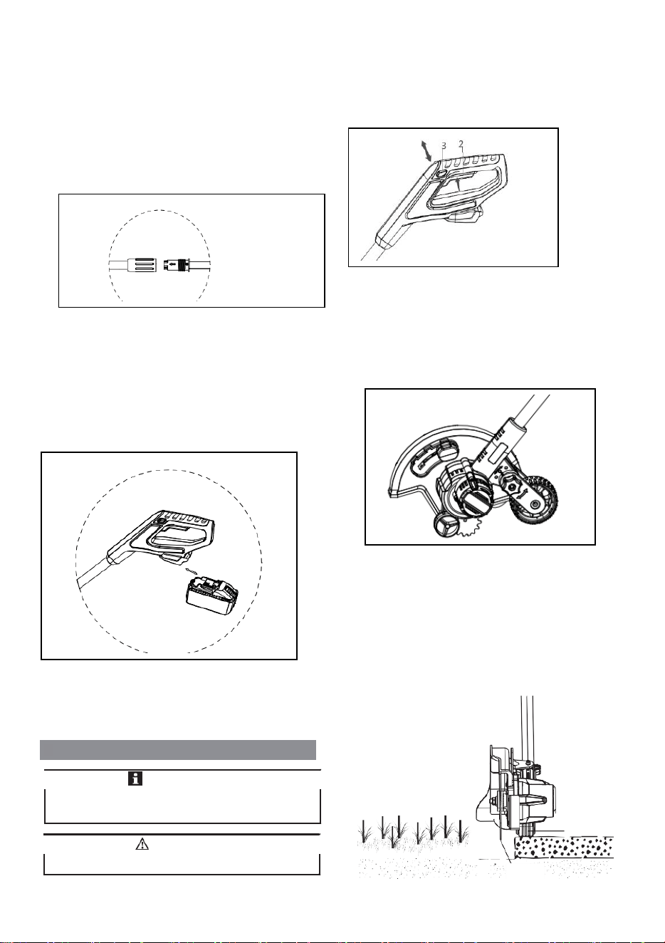
9.3 ADJUST THE DEPTH OF CUT
1. Remove the battery pack.
2. Loosen the depth adjustment knob to increase or decrease
the depth.
8.5 REMOVE THE BATTERY PACK
1. Push and hold the battery release button (1).
2. Remove the battery pack from the machine.
9 OPERATION
Depth Adjustment Knob
3. Adjust the depth so that the blade barely touches the
ground when the machine is held in a normal operating
posture.
4. Tighten the depth adjustment knob.
5. Standing in a normal working position, check the depth of
cut again and correct if necessary.
6. Replace the battery pack once all adjustments are
complete.
9.1 START THE MACHINE
1. Push the lock-out lever (3) and pull the trigger (2).
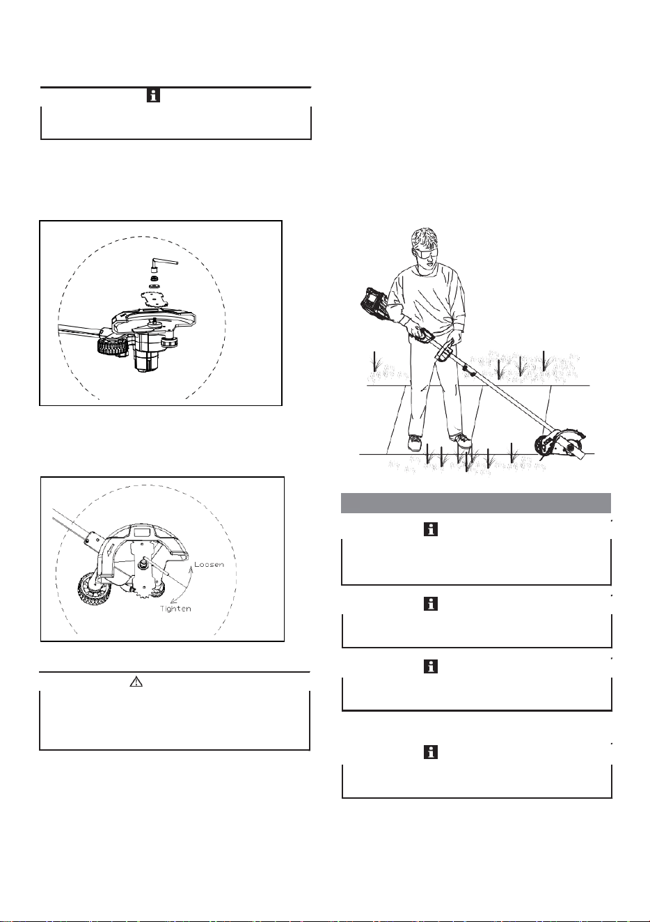
9.4 REPLACE THE BLADE
9.2 STOP THE MACHINE
1. Release the trigger to stop the machine.
1. Use a metal rod to fix the blade.
2. Remove the nut by turning it clockwise with the
wrench provided.
3. Remove the washer.
Be careful when you operate the machine.
WARNING
If the blade worn out, replace it with a new one (not
provided).
NOTE
Before you operate the machine, read and understand the
safety regulations and the operation instructions.
IMPORTANT
Wheel
Blade
8
9.3 ADJUST THE DEPTH OF CUT
1. Remove the battery pack.
2. Loosen the depth adjustment knob to increase or decrease
the depth.
8.5 REMOVE THE BATTERY PACK
1. Push and hold the battery release button (1).
2. Remove the battery pack from the machine.
9 OPERATION
Depth Adjustment Knob
3. Adjust the depth so that the blade barely touches the
ground when the machine is held in a normal operating
posture.
4. Tighten the depth adjustment knob.
5. Standing in a normal working position, check the depth of
cut again and correct if necessary.
6. Replace the battery pack once all adjustments are
complete.
9.1 START THE MACHINE
1. Push the lock-out lever (3) and pull the trigger (2).
9.4 REPLACE THE BLADE
9.2 STOP THE MACHINE
1. Release the trigger to stop the machine.
1. Use a metal rod to fix the blade.
2. Remove the nut by turning it clockwise with the
wrench provided.
3. Remove the washer.
Be careful when you operate the machine.
WARNING
If the blade worn out, replace it with a new one (not
provided).
NOTE
Before you operate the machine, read and understand the
safety regulations and the operation instructions.
IMPORTANT
Wheel
Blade
8
9.3
ADJUST THE DEPTH OF CUT
1.
Remove the battery pack.
2.
Loosen the depth adjustment knob to increase or decrease
the depth.
8.5 REMOVE THE BATTERY PACK
1. Push and hold the battery release button (1).
2. Remove the battery pack from the machine.
9 OPERATION
Depth Adjustment Knob
3.
Adjust the depth so that the blade barely touches the
ground when the machine is held in a normal operating
posture.
4.
Tighten the depth adjustment knob.
5.
Standing in a normal working position, check the depth of
cut again and correct if necessary.
6.
Replace the battery pack once all adjustments are
complete.
9.1 START THE MACHINE
1. Push the lock-out lever (3) and pull the trigger (2).
9.4 REPLACE THE BLADE
9.2 STOP THE MACHINE
1. Release the trigger to stop the machine.
1. Use a metal rod to fix the blade.
2. Remove the nut by turning it clockwise with the
wrench provided.
3. Remove the washer.
Be careful when you operate the machine.
WARNING
If the blade worn out, replace it with a new one (not
provided).
NOTE
Before you operate the machine, read and understand the
safety regulations and the operation instructions.
IMPORTANT
Wheel
Blade
8
9.3 ADJUST THE DEPTH OF CUT
1. Remove the battery pack.
2. Loosen the depth adjustment knob to increase or decrease
the depth.
8.5 REMOVE THE BATTERY PACK
1. Push and hold the battery release button (1).
2. Remove the battery pack from the machine.
9 OPERATION
Depth Adjustment Knob
3. Adjust the depth so that the blade barely touches the
ground when the machine is held in a normal operating
posture.
4. Tighten the depth adjustment knob.
5. Standing in a normal working position, check the depth of
cut again and correct if necessary.
6. Replace the battery pack once all adjustments are
complete.
9.1 START THE MACHINE
1. Push the lock-out lever (3) and pull the trigger (2).
9.4 REPLACE THE BLADE
9.2 STOP THE MACHINE
1. Release the trigger to stop the machine.
1. Use a metal rod to fix the blade.
2. Remove the nut by turning it clockwise with the
wrench provided.
3. Remove the washer.
Be careful when you operate the machine.
WARNING
If the blade worn out, replace it with a new one (not
provided).
NOTE
Before you operate the machine, read and understand the
safety regulations and the operation instructions.
IMPORTANT
Wheel
Blade
6
Symbol
Explanation
Do not expose the machine to rain or
moist conditions.
Keep all bystanders at least 15m away.
Thrown objects can ricochet and result in
personal injury or property damage.
Danger - Keep hands and feet away from
blade.
4 RISK LEVELS
The following signal words and meanings are intended to
explain the levels of risk associated with this product.
SYM-
BOL
SIGNAL
MEANING
DANGER
Indicates an imminently haz-
ardous situation, which, if not
avoided, will result in death
or serious injury.
WARNING
Indicates a potentially hazard-
ous situation, which, if not
avoided, could result in death
or serious injury.
CAUTION
Indicates a potentially hazard-
ous situation, which, if not
avoided, may result in minor
or moderate injury.
CAUTION
(Without Safety Alert Sym-
bol) Indicates a situation that
may result in property dam-
age.
7
5 INSTALLATION
8.3 ASSEMBLE THE SHAFT
1. Turn the lower shaft towards the upper shaft.
8.1 ATTACH THE AUXILIARY
HANDLE
1. Attach the auxiliary handle (4) on the shaft.
2. Set the auxiliary handle in the most comfortable in use
position.
3. Tighten the knob.
5
2. Tighten the shaft .
8.4 INSTALL THE BATTERY PACK
.
1. Push the battery pack into the battery compartment until
the battery pack locks into place.
2. When you hear a click, the battery pack is installed.
6
5.2
5.3
5.4
6.1
6.2
6.3
3
8
9.3 ADJUST THE DEPTH OF CUT
1. Remove the battery pack.
2. Loosen the depth adjustment knob to increase or decrease
the depth.
8.5 REMOVE THE BATTERY PACK
1. Push and hold the battery release button (1).
2. Remove the battery pack from the machine.
9 OPERATION
Depth Adjustment Knob
3. Adjust the depth so that the blade barely touches the
ground when the machine is held in a normal operating
posture.
4. Tighten the depth adjustment knob.
5. Standing in a normal working position, check the depth of
cut again and correct if necessary.
6. Replace the battery pack once all adjustments are
complete.
9.1 START THE MACHINE
1. Push the lock-out lever (3) and pull the trigger (2).
9.4 REPLACE THE BLADE
9.2 STOP THE MACHINE
1. Release the trigger to stop the machine.
1. Use a metal rod to fix the blade.
2. Remove the nut by turning it clockwise with the
wrench provided.
3. Remove the washer.
Be careful when you operate the machine.
WARNING
If the blade worn out, replace it with a new one (not
provided).
NOTE
Before you operate the machine, read and understand the
safety regulations and the operation instructions.
IMPORTANT
Wheel
Blade
9
1
4. Remove the old blade and replace it with a new one.
5. Place the washer on the blade.
6. Place the nut on the washer and tighten it
counterclockwise with the wrench provided.
10 MAINTENANCE
9.5 OPERATION TIPS
• Hold the edger with your right hand on the rear handle
and your left hand on the front handle.
• Keep a firm grip with both hands while in operation.
• Edger should be held at a comfortable position with the
rear handle about hip height.
• The edger will edge along sidewalks, driveways, flower
beds, curbs, and similar areas.
• Cut at a steady pace. If the blade begins to bog down, you
are edging too fast; slow your pace. Do not force the
blade into ground.
• Light contact of the blade against the sidewalk edge,
curb, etc., is acceptable and will not damage the edger.
• Best appearance is obtained when grass is dry. Avoid
edging in wet soil or wet grass areas or the blade guard
might clog and result in an uneven edge. If the blade
guard becomes clogged, stop the edger, remove the
battery, and remove debris from the blade guard.
10.1 GENERAL INFORMATION
Before the maintenance operations:
• Stop the machine.
• Remove the battery pack.
• Cool the motor.
• Store the machine in cool and dry place.
• Use correct clothing, protective gloves and safety glasses.
10.2 CLEAN THE MACHINE
• Clean the machine after use with a moist cloth dipped in
neutral detergent.
• Do not use aggressive detergents or solvents to clean the
plastic parts or handles.
Read and understand the safety regulations and the
maintenance instructions before you clean, repair or do the
maintenance work on the machine.
IMPORTANT
Use only the replacement parts and accessories of the initial
manufacturer.
Only your dealer or approved service center can do the
maintenance that is not given in this manual.
IMPORTANT
Always hold the edger away from the body keeping
clearance between your body and the edger. Any contact
with the edger cutting head while operating can result in
serious personal injury.
WARNING
Make sure that all nuts, bolts and screws are tight. Examine
regularly that you install the handles tightly.
IMPORTANT
IMPORTANT
10
• Keep the trimmer head free of grass, leaves, or excessive
grease.
• Keep the air vents clean and free of debris to avoid
overheating and damage to the motor or the battery.
• Do not spray water onto the motor and electrical
components.
10.3 REPLACE THE SKID PLATE
1. Remove the screws with a Phillips Head screwdriver (not
included).
2. Replace with the new skid plate.
3. Tighten the screws.
11 TRANSPORTATION AND
STORAGE
1
10.4 REPLACE THE WHEEL
1. Remove the battery.
2. Remove the wing nut, washer, axle sleeve, wheel, axle
sleeve, rubber washer and wheel axle orderly from
the wheel assembly.
3. Replace with the new wheel.
4. Insert the wheel axle through the slot downward, then
put the rubber washer, axle sleeve, wheel , axle sleeve,
washer and wing nut orderly through the wheel axle .
5. Tighten the wing nut .
11.1 MOVE THE MACHINE
When you move the machine, you must:
• Stop the machine.
• Remove the battery pack.
11.2 STORE THE MACHINE
• Remove the battery pack from the machine.
• Make sure that children cannot come near the machine.
• Keep the machine away from corrosive agents such as
garden chemicals and de-icing salts.
• Secure the machine during transportion to prevent
damage or injury. Clean and examine the machine for any
damage.
12 TROUBLESHOOTING
Remove the battery pack from the machine before
transportation and storage.
WARNING
Problem
Possible Cause
Solution
The ma-
chine does
not start
when you
push the
trigger.
No electrical con-
tact between the
machine and the
battery pack.
1. Remove battery pack.
2. Check contact and in-
stall the battery pack
again.
The battery pack is
depleted.
Charge the battery pack.
The lock-out but-
ton and trigger are
not pushed at the
same time.
1. Pull the lock-out but-
ton and hold it.
2. Pull the trigger to start
the machine.
7
6.4
6.5
7.1
4

9
1
4. Remove the old blade and replace it with a new one.
5. Place the washer on the blade.
6. Place the nut on the washer and tighten it
counterclockwise with the wrench provided.
10 MAINTENANCE
9.5 OPERATION TIPS
• Hold the edger with your right hand on the rear handle
and your left hand on the front handle.
• Keep a firm grip with both hands while in operation.
• Edger should be held at a comfortable position with the
rear handle about hip height.
• The edger will edge along sidewalks, driveways, flower
beds, curbs, and similar areas.
• Cut at a steady pace. If the blade begins to bog down, you
are edging too fast; slow your pace. Do not force the
blade into ground.
• Light contact of the blade against the sidewalk edge,
curb, etc., is acceptable and will not damage the edger.
• Best appearance is obtained when grass is dry. Avoid
edging in wet soil or wet grass areas or the blade guard
might clog and result in an uneven edge. If the blade
guard becomes clogged, stop the edger, remove the
battery, and remove debris from the blade guard.
10.1 GENERAL INFORMATION
Before the maintenance operations:
• Stop the machine.
• Remove the battery pack.
• Cool the motor.
• Store the machine in cool and dry place.
• Use correct clothing, protective gloves and safety glasses.
10.2 CLEAN THE MACHINE
• Clean the machine after use with a moist cloth dipped in
neutral detergent.
• Do not use aggressive detergents or solvents to clean the
plastic parts or handles.
Read and understand the safety regulations and the
maintenance instructions before you clean, repair or do the
maintenance work on the machine.
IMPORTANT
Use only the replacement parts and accessories of the initial
manufacturer.
Only your dealer or approved service center can do the
maintenance that is not given in this manual.
IMPORTANT
Always hold the edger away from the body keeping
clearance between your body and the edger. Any contact
with the edger cutting head while operating can result in
serious personal injury.
WARNING
Make sure that all nuts, bolts and screws are tight. Examine
regularly that you install the handles tightly.
IMPORTANT
IMPORTANT
10
• Keep the trimmer head free of grass, leaves, or excessive
grease.
• Keep the air vents clean and free of debris to avoid
overheating and damage to the motor or the battery.
• Do not spray water onto the motor and electrical
components.
10.3 REPLACE THE SKID PLATE
1. Remove the screws with a Phillips Head screwdriver (not
included).
2. Replace with the new skid plate.
3. Tighten the screws.
11 TRANSPORTATION AND
STORAGE
1
10.4 REPLACE THE WHEEL
1. Remove the battery.
2. Remove the wing nut, washer, axle sleeve, wheel, axle
sleeve, rubber washer and wheel axle orderly from
the wheel assembly.
3. Replace with the new wheel.
4. Insert the wheel axle through the slot downward, then
put the rubber washer, axle sleeve, wheel , axle sleeve,
washer and wing nut orderly through the wheel axle .
5. Tighten the wing nut .
11.1 MOVE THE MACHINE
When you move the machine, you must:
• Stop the machine.
• Remove the battery pack.
11.2 STORE THE MACHINE
• Remove the battery pack from the machine.
• Make sure that children cannot come near the machine.
• Keep the machine away from corrosive agents such as
garden chemicals and de-icing salts.
• Secure the machine during transportion to prevent
damage or injury. Clean and examine the machine for any
damage.
12 TROUBLESHOOTING
Remove the battery pack from the machine before
transportation and storage.
WARNING
Problem
Possible Cause
Solution
The ma-
chine does
not start
when you
push the
trigger.
No electrical con-
tact between the
machine and the
battery pack.
1. Remove battery pack.
2. Check contact and in-
stall the battery pack
again.
The battery pack is
depleted.
Charge the battery pack.
The lock-out but-
ton and trigger are
not pushed at the
same time.
1. Pull the lock-out but-
ton and hold it.
2. Pull the trigger to start
the machine.
10
• Keep the trimmer head free of grass, leaves, or excessive
grease.
• Keep the air vents clean and free of debris to avoid
overheating and damage to the motor or the battery.
• Do not spray water onto the motor and electrical
components.
10.3 REPLACE THE SKID PLATE
1. Remove the screws with a Phillips Head screwdriver (not
included).
2. Replace with the new skid plate.
3. Tighten the screws.
11
TRANSPORTATION AND
STORAGE
1
10.4 REPLACE THE WHEEL
1. Remove the battery.
2. Remove the wing nut, washer, axle sleeve, wheel, axle
sleeve, rubber washer and wheel axle orderly from
the wheel assembly.
3. Replace with the new wheel.
4. Insert the wheel axle through the slot downward, then
put the rubber washer, axle sleeve, wheel , axle sleeve,
washer and wing nut orderly through the wheel axle .
5. Tighten the wing nut .
11.1 MOVE THE MACHINE
When you move the machine, you must:
• Stop the machine.
• Remove the battery pack.
11.2 STORE THE MACHINE
• Remove the battery pack from the machine.
• Make sure that children cannot come near the machine.
• Keep the machine away from corrosive agents such as
garden chemicals and de-icing salts.
• Secure the machine during transportion to prevent
damage or injury. Clean and examine the machine for any
damage.
12 TROUBLESHOOTING
Remove the battery pack from the machine before
transportation and storage.
WARNING
Problem
Possible Cause
Solution
The ma-
chine does
not start
when you
push the
trigger.
No electrical con-
tact between the
machine and the
battery pack.
1. Remove battery pack.
2. Check contact and in-
stall the battery pack
again.
The battery pack is
depleted.
Charge the battery pack.
The lock-out but-
ton and trigger are
not pushed at the
same time.
1. Pull the lock-out but-
ton and hold it.
2. Pull the trigger to start
the machine.
10
• Keep the trimmer head free of grass, leaves, or excessive
grease.
• Keep the air vents clean and free of debris to avoid
overheating and damage to the motor or the battery.
• Do not spray water onto the motor and electrical
components.
10.3 REPLACE THE SKID PLATE
1. Remove the screws with a Phillips Head screwdriver (not
included).
2. Replace with the new skid plate.
3. Tighten the screws.
11 TRANSPORTATION AND
STORAGE
1
10.4 REPLACE THE WHEEL
1. Remove the battery.
2. Remove the wing nut, washer, axle sleeve, wheel, axle
sleeve, rubber washer and wheel axle orderly from
the wheel assembly.
3. Replace with the new wheel.
4. Insert the wheel axle through the slot downward, then
put the rubber washer, axle sleeve, wheel , axle sleeve,
washer and wing nut orderly through the wheel axle .
5. Tighten the wing nut .
11.1 MOVE THE MACHINE
When you move the machine, you must:
• Stop the machine.
• Remove the battery pack.
11.2 STORE THE MACHINE
• Remove the battery pack from the machine.
• Make sure that children cannot come near the machine.
• Keep the machine away from corrosive agents such as
garden chemicals and de-icing salts.
• Secure the machine during transportion to prevent
damage or injury. Clean and examine the machine for any
damage.
12 TROUBLESHOOTING
Remove the battery pack from the machine before
transportation and storage.
WARNING
Problem Possible Cause Solution
The ma-
chine does
not start
when you
push the
trigger.
No electrical con-
tact between the
machine and the
battery pack.
1. Remove battery pack.
2. Check contact and in-
stall the battery pack
again.
The battery pack is
depleted.
Charge the battery pack.
The lock-out but-
ton and trigger are
not pushed at the
same time.
1. Pull the lock-out but-
ton and hold it.
2. Pull the trigger to start
the machine.
7.2
7.3
7.4
8.1
8.2
8
9
5
11
13 TECHNICAL DATA
Model EGDCB20
Type Cordless, battery powered
Motor 20V
No load speed 3100±10% RPM
Blade length 9 in. (228 mm)
Weight
10 lbs (4.55 kg)
10