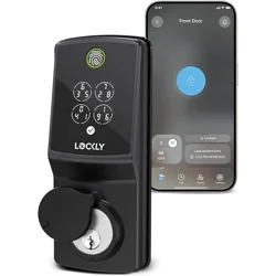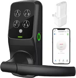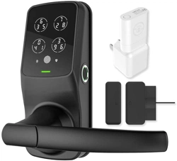
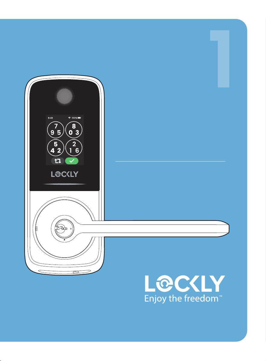
Lockly Secure Pro
Latch Edition
2025 Version
Installation guide
PGD628WE1
Welcome
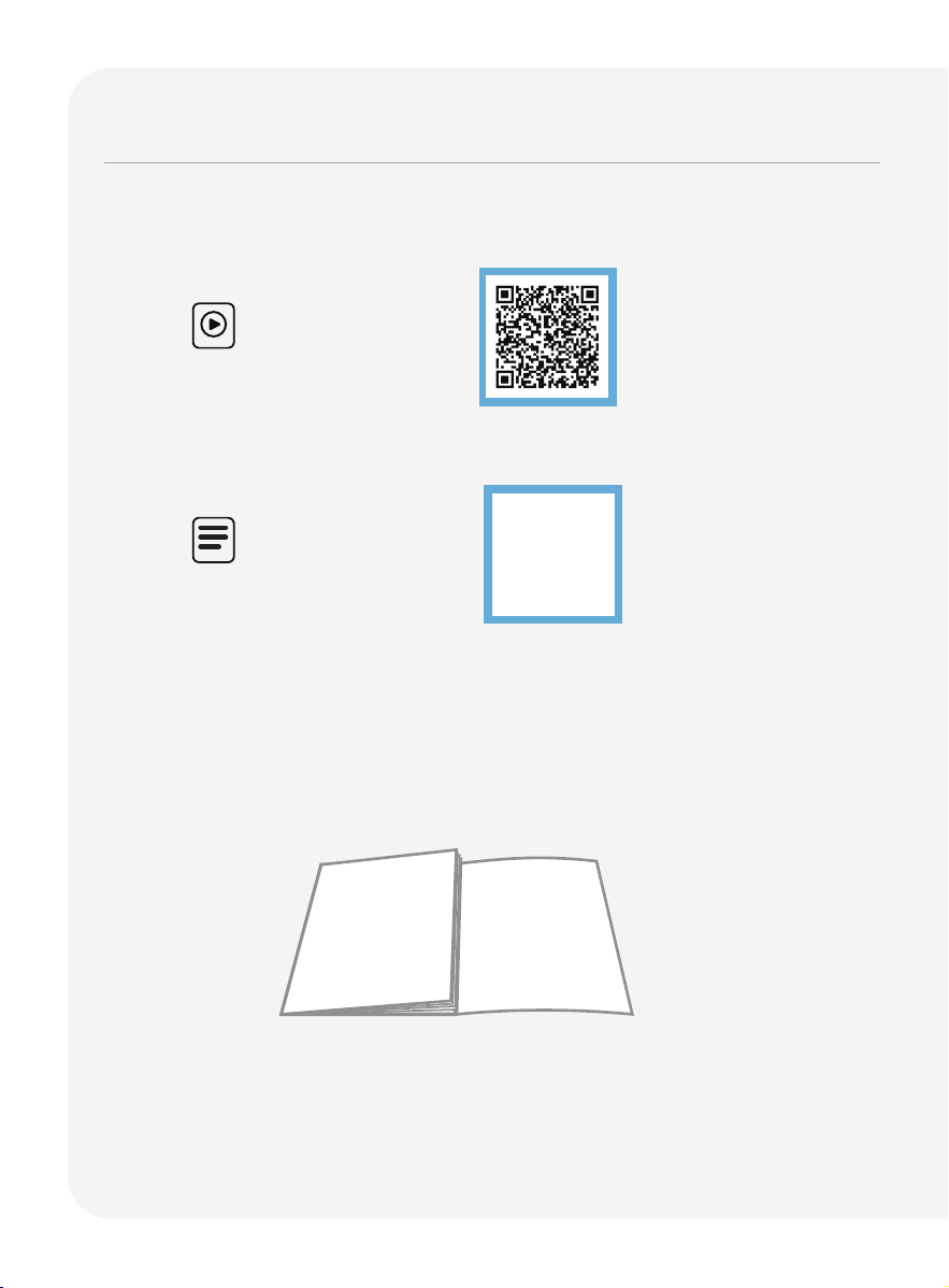
Access the latest Install video and installation guide.
Scan to watch
step-by-step
video installation
Reference foldout
Get an overview of all installation components and parts with the handy
reference foldout on the back page. Keep it open for reference as you go
through each step.
Scan for the most
updated version
of this manual.

We’re here to help
Your Lockly smart lock includes
lifetime support. If you get locked
out, have any issues, or want to
share feedback, just contact us,
and we’ll help you quickly.
(669) 500-8835 [email protected] support.Lockly.com
02
03
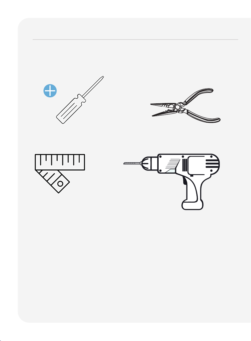
What you’ll need
Phillips Screwdriver
To complete the installation you will need:
Tape measure or ruler
Vise
(Optional)
(Optional)
Screwdriver with drill bits
You don’t need to drill to put the lock on an existing door. However if you are
installing your lock on a brand new door, a drill is required if there are no
holes prepared for lock installation.
04
What you’ll need
continued
* You are not required to drill an extra hole in your door.
We have provided double-sided adhesive tape for you
to help stabilize the lock during installation. Only drill a
hole
if you wish to have
added stability. Please refer to the
provided template for drilling
if needed. Use goggles to
protect your eyes if you need to drill
door holes.
Remove existing door hardware, latch or deadbolts before installing the
new lock. Use provided template to bore new holes if needed.
1
2
3
4
Measure and confirm your door thickness is between
1 3/8
" ~ 2"
(35mm ~ 50mm).
Measure and confirm the bore hole in the door is 2 1/8
" (54mm)
.
Measure and confirm that cross bore in the door edge is 1" (25.4mm).
Measure and confirm that the backset is either 2 3/8" (60mm) or
2 3/4" (70mm).
1 3/8"~2"
(35mm~50mm)
2 3/8"(60mm)
or
2 3/4"(70mm)
2 1/8"
54mm
4 1/8"(105mm)
1/2"
12mm
1"
25.4mm
*
*
*Optional
Hole for fastener
05
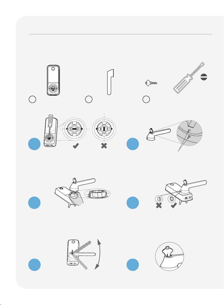
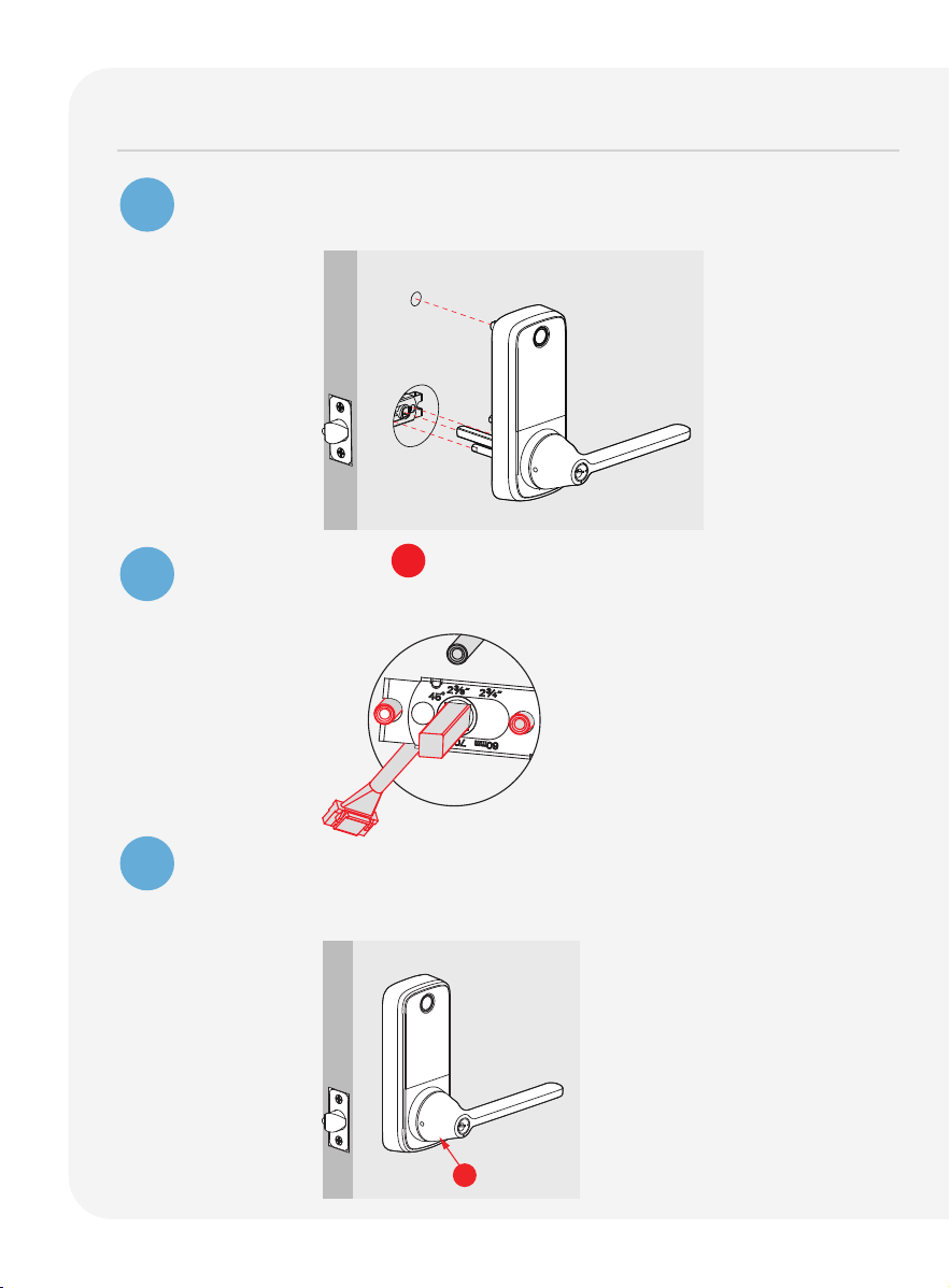
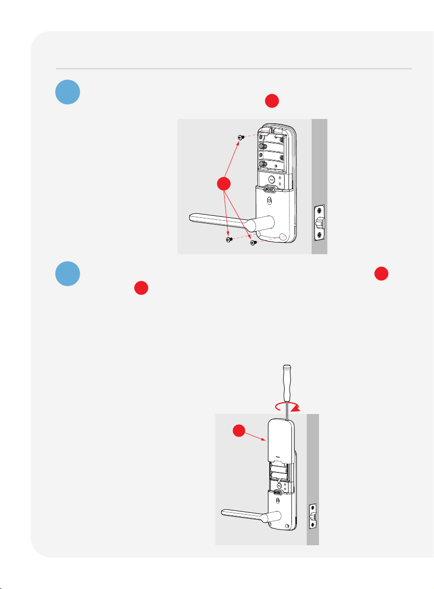
Key
IMPORTANT:
Before installing the smart lock, follow the below steps on this page
to complete the installation of the Exterior Door Handle Set.
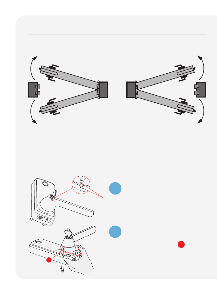
Installation Instructions
Exterior Assembly Door Handle Set
Use a flathead screwdriver to rotate
the sleeve to a horizontal position,
aligning the notches on both sides
with the spring pin.
Insert key and rotate lock face so
that the two pit points align as
shown.
Using your fingers, press the two pins
located on the left and right side of
the lock to insert the handle back
onto the lock.
After confirming that the installation
is complete, check whether the pin
is popped up. Adjust the handle
accordingly to ensure that the pins
are fully released.
Check that your handle moves
smoothly by turning it up and down.
Rotate the key to horizontal and
remove it.
B B2 A
Flathead Screwdriver
1
2
3
4
5
6
Installation of Exterior Door Handle Set

Installation
Installing the lockset 06Installing the lockset 06
Changing handle for right or left swing doors 07 ~ 09Changing handle for right or left swing doors 07 ~ 09
Preparing lock for installation 10 Preparing lock for installation 10
Installing the lock (exterior) 11Installing the lock (exterior) 11
Installing the lock (interior) 12 ~ 15Installing the lock (interior) 12 ~ 15
Installing the door strike 16 ~ 18 Installing the door strike 16 ~ 18
Troubleshooting/FAQs 19 ~ 20Troubleshooting/FAQs 19 ~ 20
06
Installing the lockset
Facing the door exterior, install the lockset according to the in-swing or
out-swing opening direction of your door.
Secure lockset with provided G screws.
The shaft's horizontal and vertical alignment must be sustained
during installation to ensure latch will fully extend and lock
securely.
LEFT OUT-SWING DOOR
Inside
Outside
LEFT IN-SWING DOOR
Inside
Outside
RIGHT IN-SWING DOOR
Inside
Outside
RIGHT OUT-SWING DOOR
Inside
Outside
To ensure normal functions and stable
l
ong-term operation of this lockset,
replace your door’s old lockset with
the provided Lockly lockset. The included
lockset is designed and optimized for
Lockly smart locks.
Measure the distance between center
of front door hole to the edge of your
door. Push the shaft (a) to adjust the
lockset to 2 3/8"(60mm) or 2 3/4"
(70mm).
(a)
Latch Adjustment
Push the shaft (a)
to adjust the lockset
to 2 3/8"(60mm) or
2 3/4"(70mm).
2 3/4" (70mm)
2 3/8"(60mm)
07
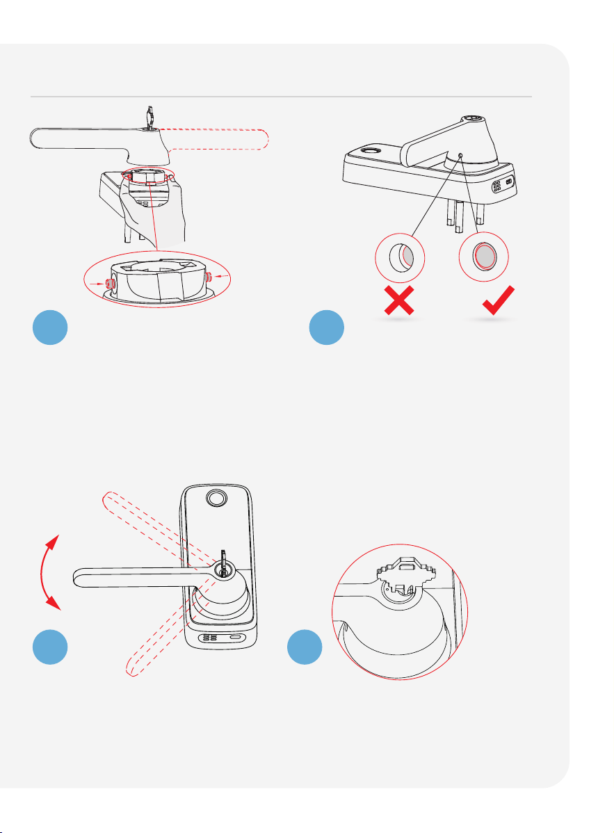
Changing handle for right or left swing doors
The lock ships with handle default for right in-swing or left out-swing door.
Check the diagram below if you are unsure of you door orientation.
Changing the Exterior Handle Orientation
(Right handle)
Insert the key and turn the lock face
until the two pit points align as shown.
1
2
Use the provided pin insert R to press
the metal pins located at the 3 o'clock
and 9 o'clock positions on the base
handle
. Remove the handle
once the
pins are compressed.
No need to change door handle
orientation. Skip Step 2.
LEFT IN-SWING and RIGHT OUT-SWING
DOORS require changing the door
handle orientation. Continue to follow
Step 2 to change exterior and interior
door handle orientation.
Hinge
Side
RIGHT IN-SWING DOOR
LEFT OUT-SWING DOOR RIGHT OUT-SWING DOOR
LEFT IN-SWING DOORINTERIOR
EXTERIOR
R
08
Changing handle for right or left swing doors continued
Check that your handle moves
smoothly by turning it up and
down.
Rotate the key to horizontal and
remove it.
3
4
5
6
Rotate the handle 180°.
Using your fingers, press the two
pins located
on the left and right
side of the lock to insert the handle
back onto the lock.
After confirming that the installation
is complete, check whether the
pin is popped up. Adjust the handle
accordingly to ensure that the
pins are fully released.
09
Remove the screw by turning counter
clockwise and rotate the handle 180°
in the direction of the arrow as shown.
Make sure the screw hole is aligned
with the marker.
Changing the Interior Handle Orientation
Securely screw clockwise as shown
to complete your handle orientation
change.
1
2
Changing handle for right or left swing doors continued
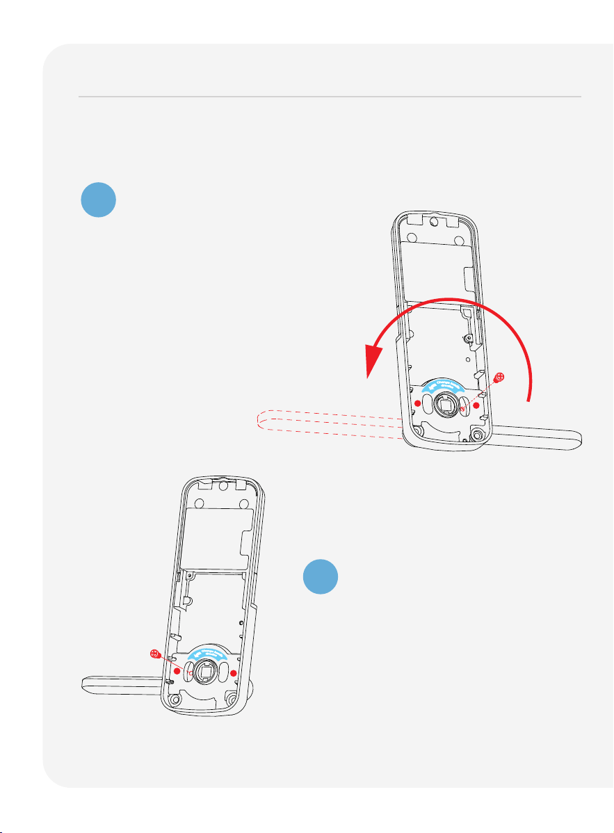
10
Preparing lock for installation
If you drilled a hole during preparation, use a vise to secure the Slotted
Barrel Extension and tighten it clockwise.
Peel off the paper
layer from the adhe-
sive tape to prepare
for installation.
2
1
Position Spindle C so that the
holes are
facing the base of
the lock.
Press and hold the pegs while
inserting
them into the square slot of the internal
rotating
shaft. Ensure
that the pegs are aligned
with the direction
of the
side holes of the internal
rotating shaft.
1
The pegs will pop out
through
the side holes
of the internal rotating
shaft once they are
successfully inserted.
U
C
1
2
U
C
11
Installing the lock (exterior)
1
2
3
Install the exterior assembly as shown by aligning the lock straight
and passing the cable and attached rods through the lockset.
Pass the Spindle C through the center of the lockset, and the
round rods through the sides in their respective holes. The cable
should run underneath the lockset.
Align the lock straight and press down firmly (if
you use the
adhesive tape in step 2 of "Preparing lock for installation")
to
secure the top of the lock.
B
Exterior
Exterior
12
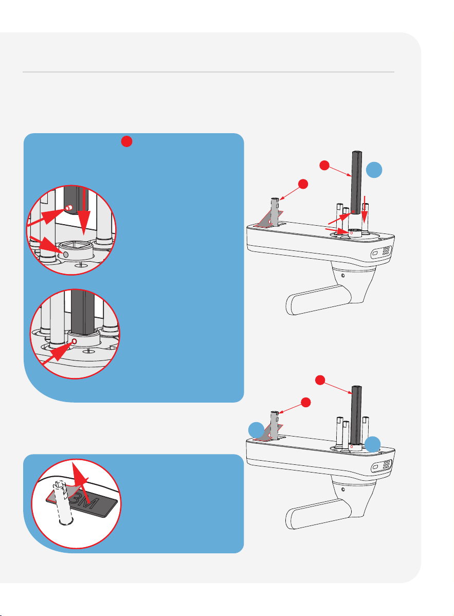
Installing the lock (interior)
Positioning rods slide
through these holes.
Mounting Plate LK
Interior Mounting Plate LK will be installed on
the interior side of your
door. Remove the
paper layer from the adhesive tape and
align the
positioning rods at the bottom
of the plate with left and
right holes.
Install the side with the black plastic seal
against the door.
1
2
Insert Positioning Rods V into the
holes on the left and right of
the
Spindle
C .
Interior
V
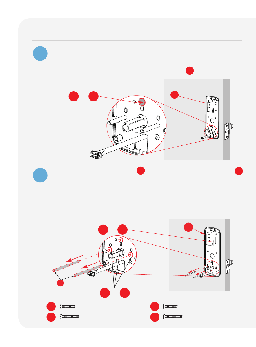
13
Installing the lock (interior) continued
Gently pull the cable from the lock exterior
through the rectangular
hole
underneath the positioning rods and spindle.
Secure the hole above the spindle
with screws O .
Remove the position rods V and
replace them with screws O
Tighten
clockwise to secure the mounting plate.
* If you have drilled a hole on the top during preparation,
please secure with screw M1 or M2 depending on your door
thickness. Skip this if
no hole was drilled during preparation.
3
4
Secure with O1 or O2
Secure with O1 or O2
PM5 x 25mm
PM5 x 35mm
M1
M2
O1
O2
LK
V
LK
*Secure top with M1 or M2
PM4 x 25mm
PM4 x 32mm
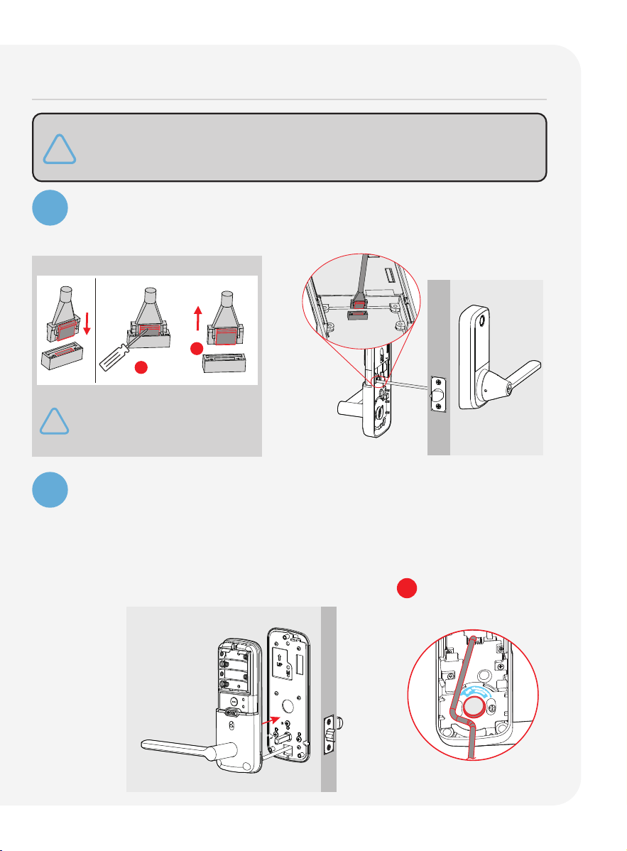
14
5
6
Plug the cable into the lock's interior assembly by aligning the pins
on the head with the holes in the slot, then gently push it in until it
fits snugly.
Install Cable Remove Cable
Align the square rod to the interior assembly and attach
the interior
assembly to the mounting plate.
Gently push excess cable through the rectangular hole into the door.
Place the remaining cable against the interior assembly to secure
it to the mounting plate.
Make sure the cable is clear of the square rod C to avoid tangling.
If you need to disconnect this cable,
use a flathead screwdriver to hold
down the tab before carefully
unplugging. DO NOT FORCE as this
may result in damaging the lock.
1
2
d
i
r
e
c
t
i
o
n
C
h
a
n
g
e
h
a
n
d
l
e
Installing the lock (interior) continued
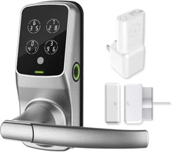
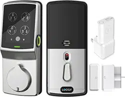
The package includes wired door sensor accessories. Installation
is optional. If you choose to install them, please refer to the
instruction page for the door sensors.
15
7
8
Once the interior assembly is flush with the mounting plate, secure
it by tightening the provided screws P clockwise.
Insert 4 AA batteries into the lock by aligning the positive + and
negative - orientation markings on the batteries to the battery
chamber.
Check if the lock powers on successfully and functions properly after
installing the batteries. Then, secure the battery cover by sliding it
over the lock and tightening the screw on top clockwise.
Q
P
Installing the lock (interior) continued
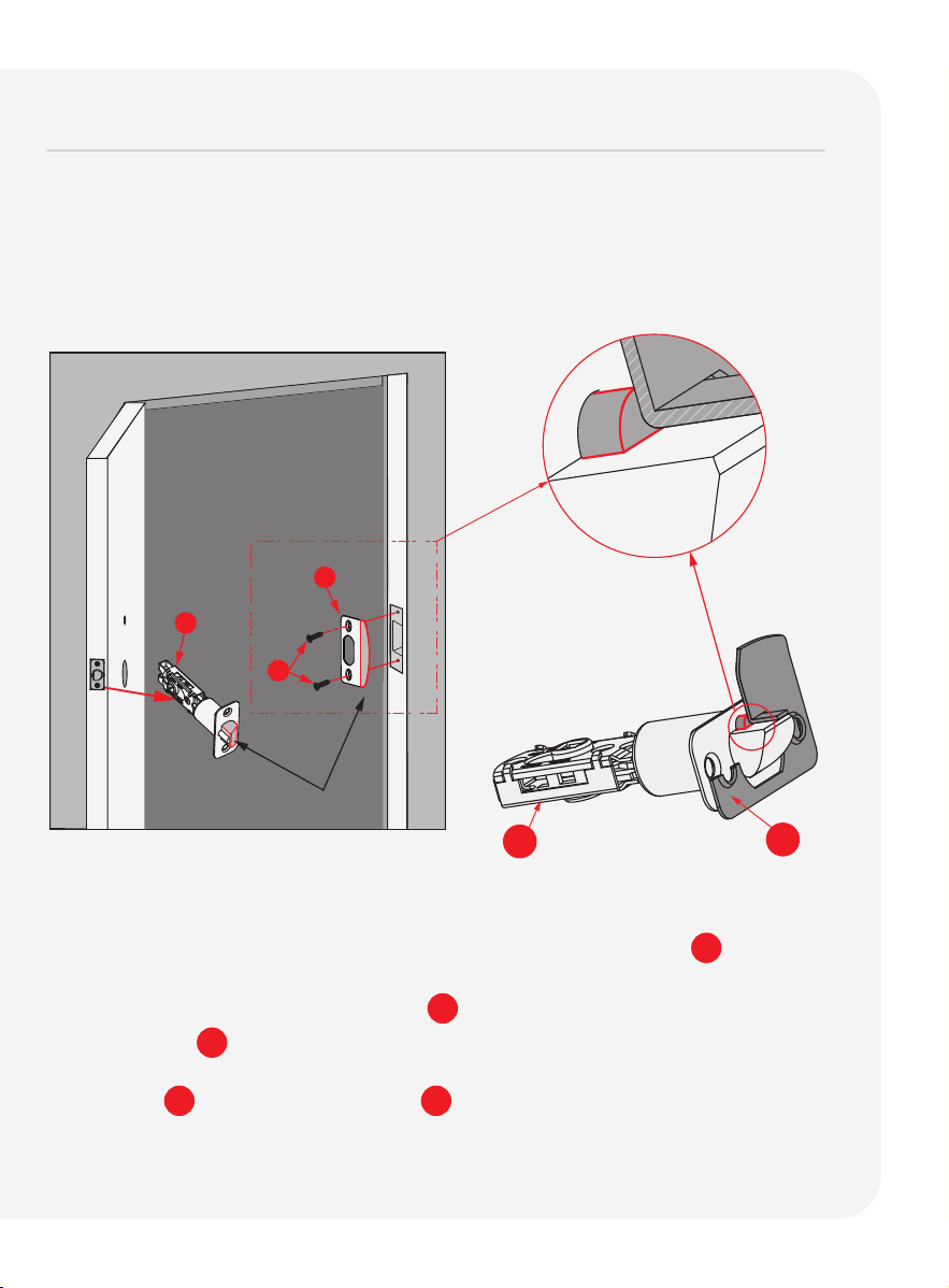
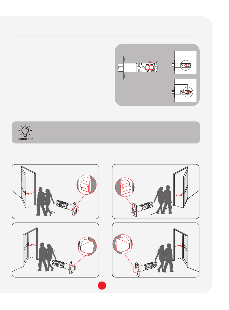
16
Installing the door strike
Make sure the slanted side of Latch F is closing against the slanted part
of Strike Plate H before securing it to the door frame.
Close your door to see if the lock aligns securely with your existing door
strike. If it does, you can keep the current strike without removing the old
hardware.
For optimal performance, we recommend using our door strike.
G
H
F
F
H
IMPORTANT: Check the alignment of the screw
holes of both the latch
and
the strike. Ensure the latch plunger is against the Strike Plate H .
Use screw G to install Strike Plate H .
17
Continue to Setup and Use
Refer to guide number 2 "Setup and Use" to complete installation.
Scan for the most
updated version.
Lockly Secure Pro
Latch Edition
2025 Version
Setup and Use
PGD628WE1

Troubleshooting
FAQs

19
Troubleshooting/FAQs
Can I install the smart lock myself, or do I need a professional?
Locky smart locks are designed to install yourself by following the provided
step-by-step installation guide or online video instructions. However, if you’re
not comfortable with DIY installations, hiring a professional is recommended.
Does Lockly offer professional installation support services?
We offer free White Glove installation support. Please schedule the installation
support with us via email at [email protected], customer support: (669)
500-8835 or our help portal at Lockly.com/help.
How do I know if my door fits a LOCKLY lock?
Before purchasing, it's a good idea to measure your door's thickness and
backset accurately and compare these measurements with the specifications
provided by Lockly. If you have any doubts or questions, our customer support
or installation guides can provide additional assistance to ensure a proper
fit for your door.
Where can I download the Installation Video and Manuals?
For comprehensive video tutorials and manual guides on installing Lockly
locks, please visit lockly.com/pages/installation.
How to re-key a LOCKLY smart lock?
Lockly uses 5-pin cylinders for the Deadbolt Editions, which can be replaced
using rekeying kits from various brands. Always follow the specific instructions
provided by Lockly for your model, as rekeying procedures can vary. If you
need clarification or are uncomfortable with rekeying, we recommend
seeking help from a professional locksmith. to ensure it's done correctly
and efficiently.
How long does the installation process take?
The installation process usually takes about 20-35 minutes, depending on
your experience and the type of door.

20
Troubleshooting/FAQs
Is Lockly compatible with all types of doors?
Lockly is compatible with most left and right swinging standard doors.
However, it’s important to check the specifications to ensure compatibility
with your door type. Doors thicker than 2 inches (50mm) may require an
optional longer torque plate and screws available through Lockly customer
service at: [email protected] or (669) 500-8835.
What should I do if the smart lock doesn’t fit my door?
If the smart lock doesn’t fit, you may need to make minor adjustments to
your door, door frame or consult Lockly customer service at:
[email protected] or (669) 500-8835 for assistance.
How do I connect the smart lock to my Wi-Fi network?
After installing the lock, follow the instructions in the app to connect it to
your Wi-Fi network. You’ll need your Wi-Fi password handy.

21
FCC Warning:
This device complies with Part 15 of the FCC Rules. Operation is subject to the following two
conditions: (1) This device may not cause harmful interference, and (2) this device must
accept any interference received, including interference that may cause undesired operation.
NOTE 1: This equipment has been tested and found to comply with the limits for a Class B digital
device, pursuant to part 15 of
the FCC Rules. These limits are designed to provide reasonable
protection against harmful interference in a residential installation.
This equipment generates,
uses and can radiate radio
frequency energy and, if not installed and used in accordance with
the instructions, may cause harmful
interference to radio communications. However, there is no
guarantee that interference will not occur
in a particular installation. If this equipment does cause
harmful interference to radio or television reception, which can be determined by turning the
equipment
off and on, the user is encouraged to try to correct
the interference by one or more
of the following measures:
- Reorient or relocate the receiving antenna.
- Increase the separation between the equipment and receiver.
-
Connect the equipment into an outlet on a circuit different from that to which the receiver is
connected.
- Consult the dealer or an experienced radio/TV technician for help.
NOTE 2: Any changes or modifications to this unit not expressly approved by the party
responsible for compliance could void the user's authority to operate the equipment.
FCC Radiation Exposure Statement
This equipment complies with FCC radiation exposure limits set forth for an uncontrolled
environment.
It should be installed and operated with minimum distance 20cm between the
radiator & your body.
IC WARNING
This equipment contains licence-exempt transmitter(s) that comply with Innovation, Science and
Economic Development Canada’s
licence-exempt RSS(s). Operation is subject to the following
two conditions:
(1) This device may not cause interference.
(2)
This device must accept any interference, including interference that may cause undesired
operation
of the device.
L’émetteur/récepteur exempt de licence contenu dans le présent appareil est conforme aux
CNR d’Innovation, Sciences et Développement économique Canada applicables aux appareils
radio exempts de licence. L’exploitation est autorisée aux deux conditions suivantes:
1. L’appareil ne doit pas produire de brouillage;
2.
L’appareil doit accepter tout brouillage radioélectrique subi, même si le brouillage est susceptible
d’en compromettre le fonctionnement.
WARNING: Cancer risk from exposure to Lead. See www.P65Warnings.ca.gov.

We’d love your feedback.
Please let us know how your installation went or if you have any other
comments.
Our short survey takes less than 2 minutes to complete.
Scan to start
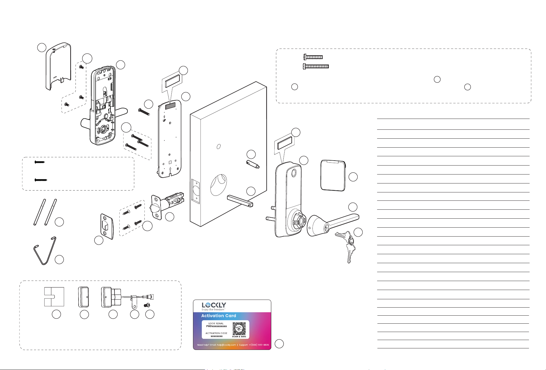
INSTALLATION OVERVIEW & PARTS LIST
Parts List
Labeled As
Description
A Keys
B
B2
Exterior Assembly
Door Handle Set
C
B1
Touchscreen Cover
Spindle
F Latch
G KA4 x 20mm Screw
H Latch Strike Plate
M PM5 Screw
N Interior Assembly
O PM4 Screw
P BM4 × 8mm Screw
Q Battery Cover
R Clamping Tool
S Interior Adhesive
T Exterior Adhesive
U Slotted Barrel Extension
V Positioning Rod
W Activation Card
LK Mounting Plate
Exterior
O1
O2
R
H
F
C
A
M
N
Q
LK
V
AA ADAEABAC
U
B1
W
O
3x
G
4x
M 1
M 2
*
T
his lock can be installed for both left or right swing doors. The lock ships ready for
a right swing door
installation. If you wish to change the orientation of the lock for a left
swing door, follow instructions on Installation
Guide (Step 2).
U
T
NOTE: You can either use the exterior adhesive or slotted barrel extension
to stabilize the exterior part. Slotted barrel extension requires drilling
an extra hole. Use provided template for drilling instructions if needed.
U
P
3x
Adhesive
T
Adhesive
S
PM5 x 25mm Screw, Door thickness 1 3/8"~1 2/3"(35~43mm)
PM5 x 35mm Screw, Door thickness 1 2/3"~2"(43~50mm)
PM4 x 25mm, for door thickness,
1 3/8"~1 2/3"(35~43mm)
PM4 x 32mm, for door thickness,
1 2/3"~2"(43~50mm)
B
AA Wired Sensor
AB Sensor Magnet
AC Foam Pads
AD BM3 × 6mm Screw
AE Cable clip
*
NOTE: The door sensor is an optional accessory,
please refer to the corresponding installation
instructions for installation if necessary.
B2

IMPGD628WE120251125
© Copyright 2025 Lockly All rights reserved
Patent No. US 9,881,146 B2 | US 9,853,815 B2 | US 9,665,706 B2 | More patents
refer to https://lockly.com/pages/our-patents
The Bluetooth
®
word mark and logos are registered trademarks owned by
the Bluetooth SIG, Inc., and any use of such marks by Lockly is under
license. Other trademarks and trade names are those of their respective
owners. Google, Android, Google Play and Google Home are trademarks
of Google LLC., Amazon, Alexa and all related logos are trademarks of
Amazon.com, Inc., or its affiliates.
Lockly Secure Pro
As always, we welcome your comments and feedback at: [email protected]