
Visit our website at: http://www.harborfreight.com
email our technical support at: [email protected]
60564
Owner’s Manual & Safety Instructions
Save This Manual Keep this manual for the safety warnings and precautions, assembly,
operating, inspection, maintenance and cleaning procedures. Write the product’s serial number in the
back of the manual near the assembly diagram (or month and year of purchase if product has no number).
Keep this manual and the receipt in a safe and dry place for future reference. 22j
When unpacking, make sure that the product is intact
and undamaged. If any parts are missing or broken,
please call 1-888-866-5797 as soon as possible.
Copyright
©
2022 by Harbor Freight Tools
®
. All rights reserved.
No portion of this manual or any artwork contained herein may be reproduced in
any shape or form without the express written consent of Harbor Freight Tools.
Diagrams within this manual may not be drawn proportionally. Due to continuing
improvements, actual product may differ slightly from the product described herein.
Tools required for assembly and service may not be included.
Read this material before using this product.
Failure to do so can result in serious injury.
SAVE THIS MANUAL.
Page 2 For technical questions, please call 1-888-866-5797. Item 60564
SaFety OperatiOn MaintenanceSetup
table of contents
Safety ......................................................... 2
Specifications ............................................. 5
Setup .......................................................... 2
Operation ................................................... 15
Maintenance .............................................. 20
Parts Lists and Diagrams .......................... 22
Warranty .................................................... 27
WarninG SyMBOLS anD DeFinitiOnS
This is the safety alert symbol. It is used to alert you to potential
personal injury hazards. Obey all safety messages that
follow this symbol to avoid possible injury or death.
Indicates a hazardous situation which, if not avoided,
will result in death or serious injury.
Indicates a hazardous situation which, if not avoided,
could result in death or serious injury.
Indicates a hazardous situation which, if not avoided,
could result in minor or moderate injury.
Addresses practices not related to personal injury.
iMpOrtant SaFety inFOrMatiOn
General tool Safety Warnings
read all safety warnings and instructions.
Failure to follow the warnings and instructions may result in electric shock, fire and/or serious injury.
Save all warnings and instructions for future reference.
1. KEEP GUARDS IN PLACE and in working order.
2. REMOVE ADJUSTING KEYS AND
WRENCHES. Form habit of checking to
see that keys and adjusting wrenches are
removed from tool before turning it on.
3. KEEP WORK AREA CLEAN.
Cluttered areas and benches invite accidents.
4. DON’T USE IN DANGEROUS ENVIRONMENT.
Don’t use power tools in damp or wet locations,
or expose them to rain. Keep work area well lighted.
5. KEEP CHILDREN AWAY. All visitors should
be kept safe distance from work area.
6. MAKE WORKSHOP KID PROOF with padlocks,
master switches, or by removing starter keys.
7. DON’T FORCE TOOL. It will do the job better
and safer at the rate for which it was designed.
8. USE RIGHT TOOL. Don’t force tool or attachment
to do a job for which it was not designed.
Page 3For technical questions, please call 1-888-866-5797.Item 60564
SaFetyOperatiOnMaintenance Setup
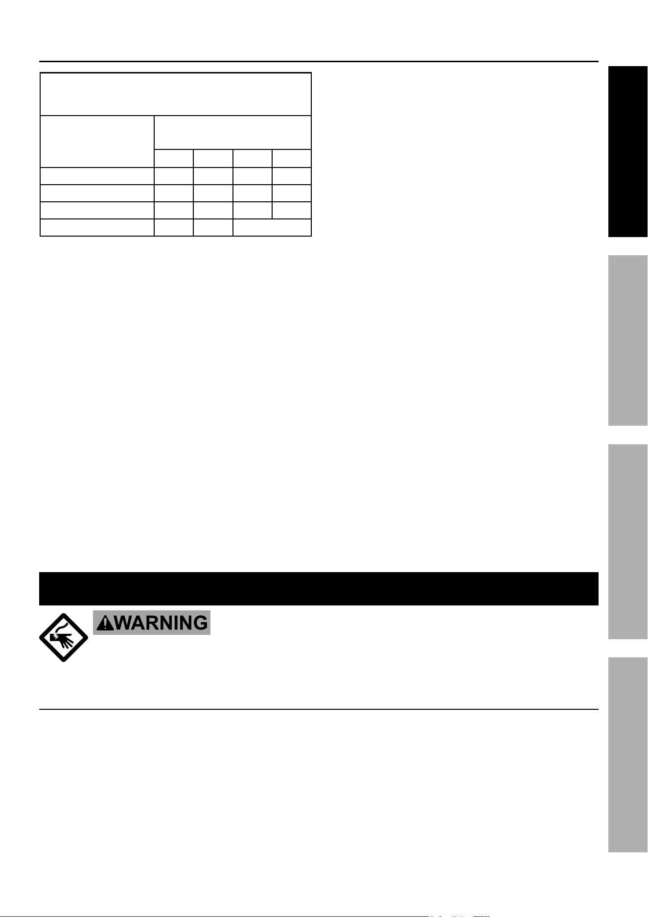
table a: recOMMenDeD MiniMuM Wire GauGe
FOr eXtenSiOn cOrDS
(120 VOLt)
naMepLate
aMpereS
(at full load)
eXtenSiOn cOrD
LenGtH
25′ 50′ 100′ 150′
0 – 6 18 16 16 14
6.1 – 10 18 16 14 12
10.1 – 12 16 16 14 12
12.1 – 16 14 12 Do not use.
9. USE PROPER EXTENSION CORD. Make sure your
extension cord is in good condition. When using
an extension cord, be sure to use one heavy
enough to carry the current your product will
draw. An undersized cord will cause a drop in line
voltage resulting in loss of power and overheating.
Table A shows the correct size to use depending
on cord length and nameplate ampere rating.
If in doubt, use the next heavier gauge.
The smaller the gauge number, the heavier the cord.
10. WEAR PROPER APPAREL. Do not wear
loose clothing, gloves, neckties, rings, bracelets,
or other jewelry which may get caught in moving
parts. Nonslip footwear is recommended.
Wear protective hair covering to contain long hair.
11. ALWAYS USE SAFETY GLASSES. Also use
face or dust mask if cutting operation is dusty.
Everyday eyeglasses only have impact resistant
lenses, they are NOT safety glasses.
12. SECURE WORK. Use clamps or a vise to hold
work when practical. It’s safer than using your
hand and it frees both hands to operate tool.
13. DON’T OVERREACH. Keep proper
footing and balance at all times.
14. MAINTAIN TOOLS WITH CARE. Keep
tools sharp and clean for best and safest
performance. Follow instructions for
lubricating and changing accessories.
15. DISCONNECT TOOLS before servicing;
when changing accessories, such as
blades, bits, cutters, and the like.
16. REDUCE THE RISK OF UNINTENTIONAL
STARTING. Make sure switch is in
off position before plugging in.
17. USE RECOMMENDED ACCESSORIES.
Consult the owner’s manual for recommended
accessories. The use of improper accessories
may cause risk of injury to persons.
18. NEVER STAND ON TOOL. Serious injury
could occur if the tool is tipped or if the
cutting tool is unintentionally contacted.
19. CHECK DAMAGED PARTS. Before further use
of the tool, a guard or other part that is damaged
should be carefully checked to determine that
it will operate properly and perform its intended
function – check for alignment of moving parts,
binding of moving parts, breakage of parts,
mounting, and any other conditions that may
affect its operation. A guard or other part that is
damaged should be properly repaired or replaced.
20. NEVER LEAVE TOOL RUNNING
UNATTENDED. TURN POWER OFF.
Don’t leave tool until it comes to a complete stop.
Grounding instructions
tO preVent eLectric SHOcK anD DeatH FrOM incOrrect GrOunDinG Wire
cOnnectiOn
reaD anD FOLLOW tHeSe inStructiOnS:
110-120 Vac Grounded tools: tools with three prong plugs
1. In the event of a malfunction or breakdown,
grounding provides a path of least resistance for
electric current to reduce the risk of electric shock.
This tool is equipped with an electric cord having an
equipment-grounding conductor and a grounding
plug. The plug must be plugged into a matching
outlet that is properly installed and grounded in
accordance with all local codes and ordinances.
2. Do not modify the plug provided – if it will
not fit the outlet, have the proper outlet
installed by a qualified electrician.
General tool Safety Warnings (cont.)
Page 4 For technical questions, please call 1-888-866-5797. Item 60564
SaFety OperatiOn MaintenanceSetup
3. Improper connection of the equipment-grounding
conductor can result in a risk of electric shock.
The conductor with insulation having an outer
surface that is green with or without yellow
stripes is the equipment-grounding conductor.
If repair or replacement of the electric cord or
plug is necessary, do not connect the equipment-
grounding conductor to a live terminal.
4. Check with a qualified electrician or service
personnel if the grounding instructions are
not completely understood, or if in doubt as
to whether the tool is properly grounded.
5. Use only 3-wire extension cords that
have 3-prong grounding plugs and 3-pole
receptacles that accept the tool’s plug.
6. Repair or replace damaged or
worn cord immediately.
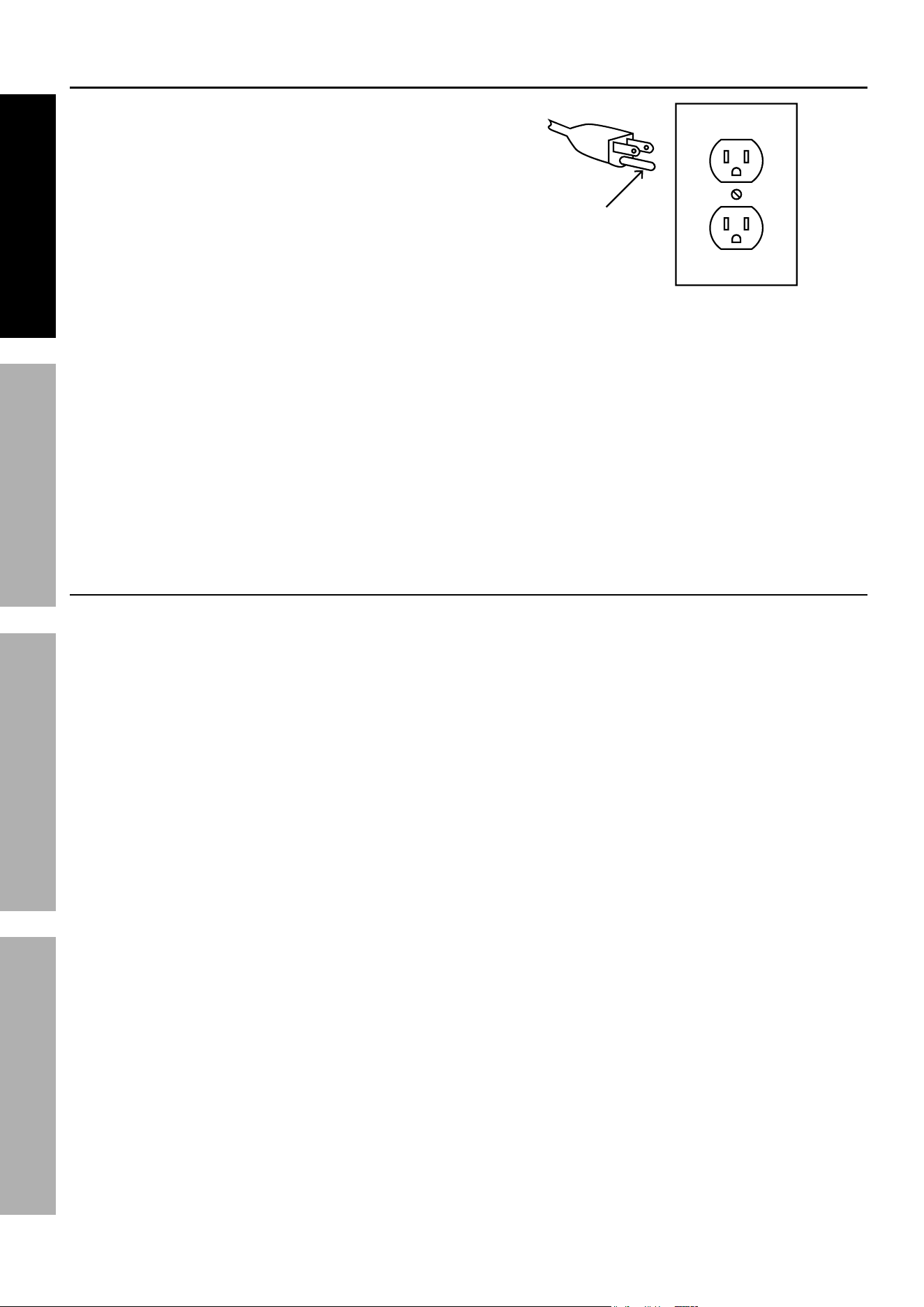
125 Vac 3-prong plug and Outlet
(for up to 125 Vac and up to 15 amps)
Grounding
pin
7. This tool is intended for use on a circuit that has
an outlet that looks like the one illustrated in
125 Vac 3-prong plug and Outlet. The tool
has a grounding plug that looks like the plug
illustrated in 125 Vac 3-prong plug and Outlet.
8. The outlet must be properly installed and grounded
in accordance with all codes and ordinances.
9. Do not use an adapter to connect
this tool to a different outlet.
Bandsaw Safety Warnings
For your Own Safety read instruction
Manual Before Operating Bandsaw
1. Wear eye protection.
2. Do not remove jammed cutoff pieces
until blade has stopped.
3. Maintain proper adjustment of blade tension,
blade guides, and thrust bearings.
4. Adjust upper guide to just clear workpiece.
5. Hold workpiece firmly against table.
6. For safe operation, the upper blade guide, the
blade tension, and the thrust bearing must
all be properly adjusted before operation.
Carefully follow the aSSeMBLy instructions,
and specifically ″Saw Blade installation″ in
Operating Instructions, for an explanation of
how to make the needed adjustments.
7. Use special care when unpacking or replacing
Bandsaw blade. Blade can be under tension
and may suddenly uncoil. Wear ANSI-
approved safety glasses under a full face
shield and heavy-duty work gloves.
8. DO nOt Operate WitH any GuarD
DiSaBLeD, DaMaGeD, Or reMOVeD. Moving
guards must move freely and close instantly.
9. The use of accessories or attachments not
recommended by the manufacturer may
result in a risk of injury to persons.
10. When servicing use only identical replacement parts.
11. Only use safety equipment that has been approved
by an appropriate standards agency. Unapproved
safety equipment may not provide adequate
protection. Eye protection must be ANSI-approved
and breathing protection must be NIOSH-approved
for the specific hazards in the work area.
12. Stay alert, watch what you are doing and use
common sense when operating a power tool.
Do not use a power tool while you are tired or
under the influence of drugs, alcohol or medication.
A moment of inattention while operating power
tools may result in serious personal injury.
13. Industrial applications must follow OSHA guidelines.
14. Maintain labels and nameplates on the tool.
These carry important safety information.
If unreadable or missing, contact
Harbor Freight Tools for a replacement.
15. Avoid unintentional starting.
Prepare to begin work before turning on the tool.
16. People with pacemakers should consult their
physician(s) before use. Electromagnetic fields in
close proximity to heart pacemaker could cause
pacemaker interference or pacemaker failure.
Grounding instructions (cont.)
Page 5For technical questions, please call 1-888-866-5797.Item 60564
SaFetyOperatiOnMaintenance Setup
17. The warnings, precautions, and instructions
discussed in this instruction manual cannot
cover all possible conditions and situations
that may occur. It must be understood by the
operator that common sense and caution are
factors which cannot be built into this product,
but must be supplied by the operator.
Vibration Safety
This tool vibrates during use. Repeated or long-term exposure to vibration may cause temporary or permanent
physical injury, particularly to the hands, arms and shoulders. To reduce the risk of vibration-related injury:
1. Anyone using vibrating tools regularly or for an
extended period should first be examined by a
doctor and then have regular medical check-ups
to ensure medical problems are not being caused
or worsened from use. Pregnant women or
people who have impaired blood circulation to
the hand, past hand injuries, nervous system
disorders, diabetes, or Raynaud’s Disease should
not use this tool. If you feel any medical or
physical symptoms related to vibration (such as
tingling, numbness, and white or blue fingers),
seek medical advice as soon as possible.
2. Do not smoke during use. Nicotine reduces
the blood supply to the hands and fingers,
increasing the risk of vibration-related injury.
3. Use tools with the lowest vibration when there
is a choice between different processes.
4. Include vibration-free periods each day of work.
5. Grip tool as lightly as possible (while still keeping
safe control of it). Let the tool do the work.
6. To reduce vibration, maintain the tool as
explained in this manual. If any abnormal
vibration occurs, stop use immediately.
SaVe tHeSe inStructiOnS.
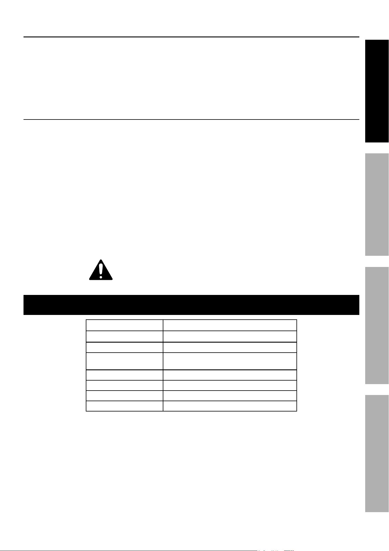
Specifications
Electrical Rating 120VAC / 60Hz / 7.1A
Max. Cutting Width 14″
Max. Cutting Height 6″
Speeds (4)
568, 1080, 1582, and 2529 FPM
(Feet Per Minute)
Table Size 14″ x 14″
Table Tilt 0-45°
Blade Size 93-1/2″ L x 3/8″ W x 0.02″ T
Table Height From Floor 42-1/2″
Bandsaw Safety Warnings (cont.)
Page 6 For technical questions, please call 1-888-866-5797. Item 60564
SaFety OperatiOn MaintenanceSetup
Setup - Before use:
read the entire iMpOrtant SaFety inFOrMatiOn section at the beginning of this manual
including all text under subheadings therein before set up or use of this product.
note: For additional information regarding the
parts listed in the following pages, refer to the
Assembly Diagram near the end of this manual.
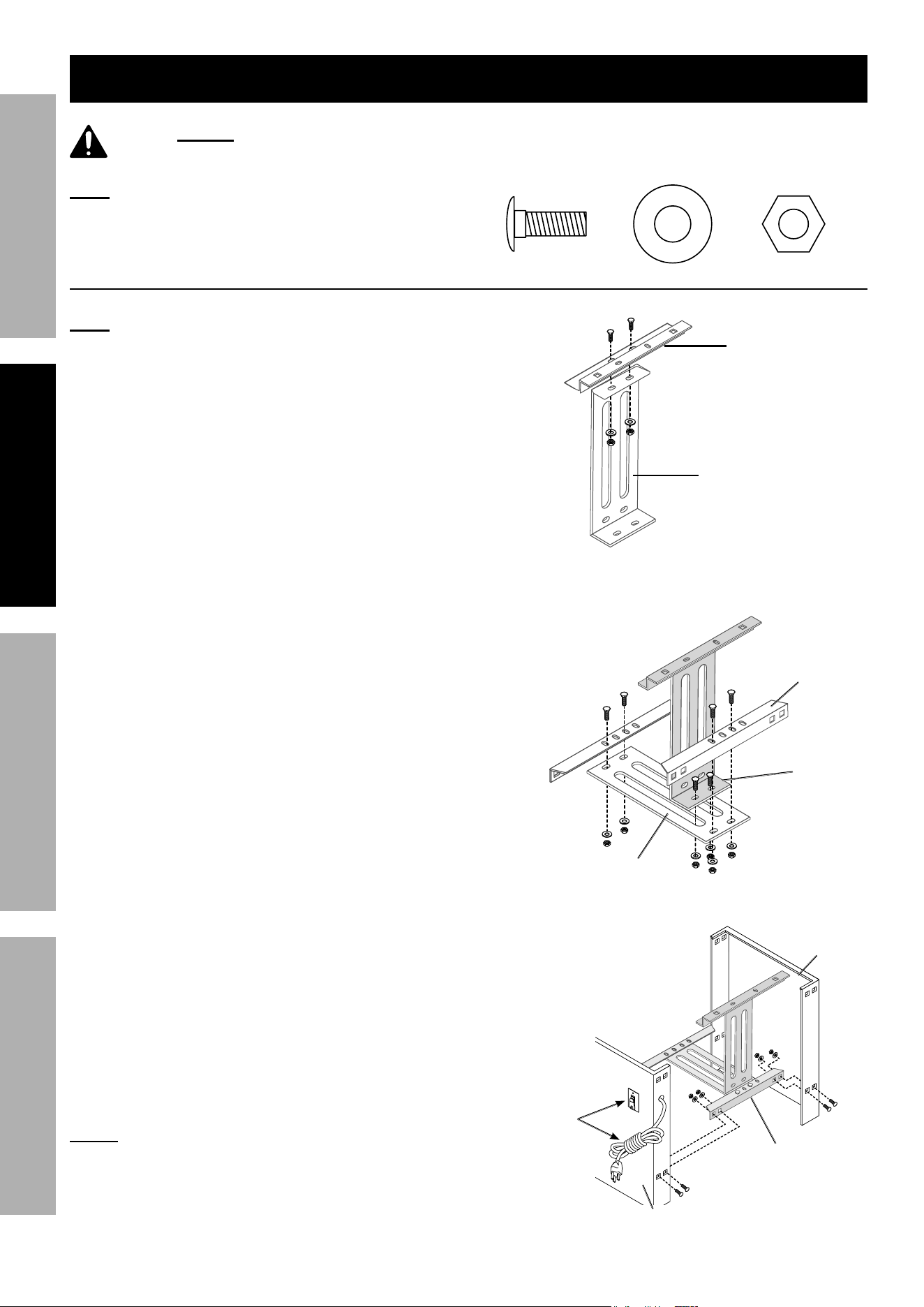
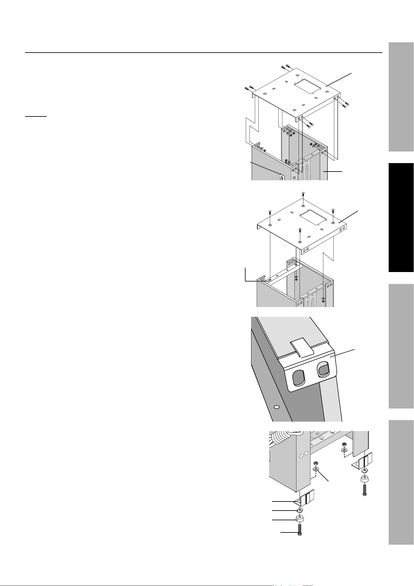
Stand assembly
note: During this phase, finger tighten all Nuts to
allow adjustment and leveling. All connections in
this phase are made with one Carriage Bolt (55)
going through the connection from the outside then
being secured with a Washer (58) and Nut (60).
1. Insert two Carriage Bolts (55) through the lower
tier of the Connecting Plate (5) and fasten to the
top end of the Motor Plate (7). The top end of
the Motor Plate has the shorter flange and the
bottom end has the longer flange. See Figure 1.
2. Fasten Supporting Plates (4) to the ends of the
Base Plate (6). Attach the Motor Plate (7) to the
end of the slots in the Base Plate. See Figure 2.
3. Fasten the Front Stand Leg (2), the one with the
power switch hole, to the left side of the Plate
assembly. Insert the carriage bolts through the
Front Stand Leg’s bottom mounting holes and into
the mounting holes on the left of the Supporting
Plate (4).
Fasten the Rear Leg (3) to the right side of the
Supporting Plate.
Fasten second Supporting Plate on the other sides
of the Front and Rear Stand Legs. See Figure 3.
nOte: See Figures 14 and 15 for instructions
on connecting the Power Switch (28)
and wiring the Power Cord (20).
Motor plate (7)
connecting
plate (5)
Figure 1
Supporting
plate (4)
Motor
plate (7)
Base plate (6)
Figure 2
power Switch (28),
power cord (20)
Front Stand Leg (2)
Supporting
plate (4)
rear Stand
Leg (3)
Figure 3
5555 5858 6060
Page 7For technical questions, please call 1-888-866-5797.Item 60564
SaFetyOperatiOnMaintenance Setup
Stand assembly
(continued)
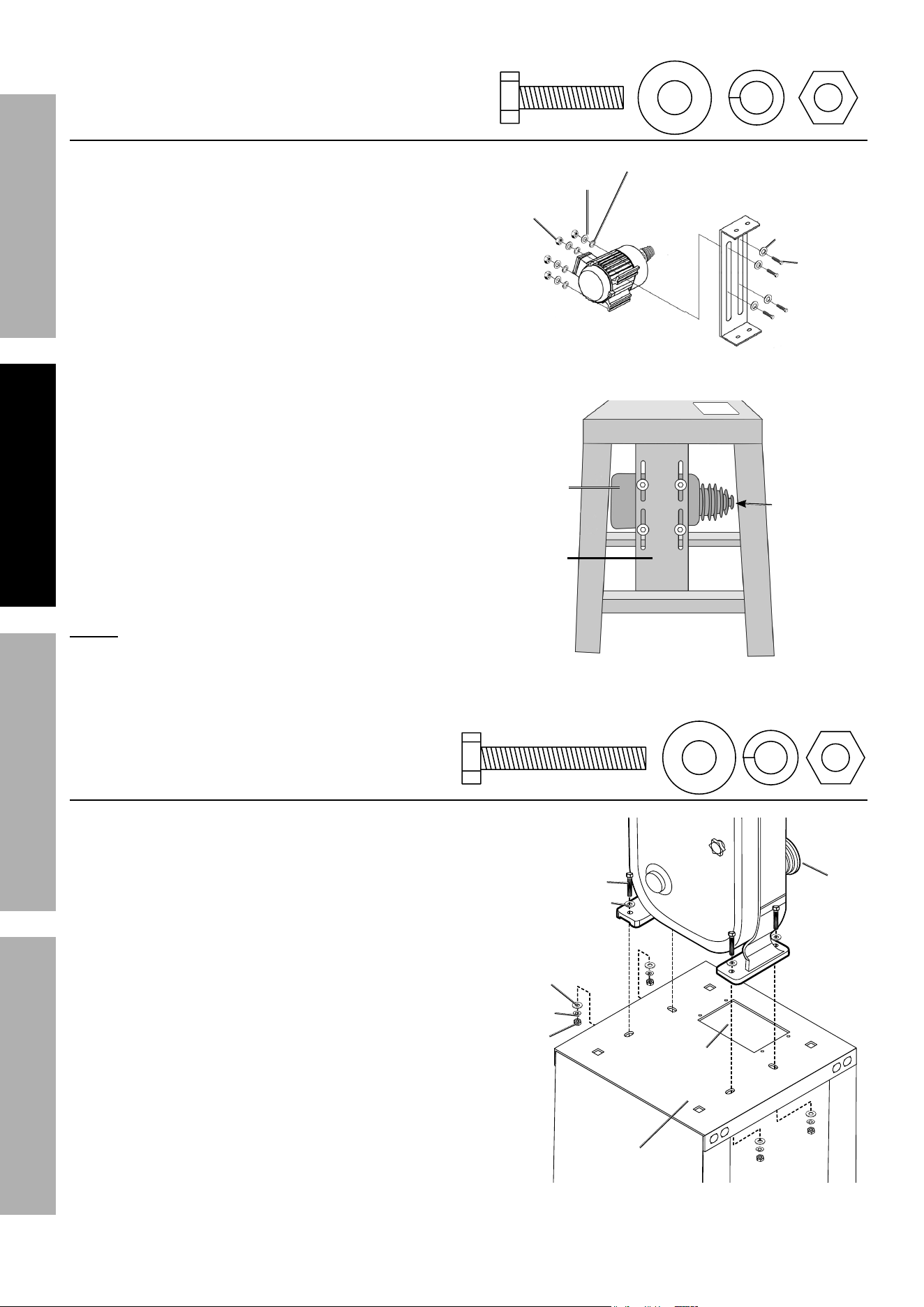
4. Set the Face Plate (1) onto the stand
assembly and fasten to the top SIDE mounting
holes on Front and Rear Stand Legs.
nOte: Be sure that the belt opening on the Face Plate
is positioned away from the power switch. See Figure 4.
5. Slide the Inner Plate (9) under the Face Plate (1)
and fasten together using the TOP mounting holes.
Then fasten to the Plate Assembly. See Figure 5.
6. Set the Fixed Plates (64) against each bottom
corner of the Front and Rear Legs, making sure the
mounting holes face downward. See Figure 6.
7. Use Hex Bolts (53) to fasten Feet (65-1),
Pads (65), and Fixed Plates (64) together.
Secure Feet to Stand bottom with the Flat
Washer (58) and Nut (60). See Figure 7.
8. Make sure Stand is level. Adjust Pad (65) on Feet
(65-1) as needed.
When level, tighten all hardware connections.
Figure 4
Face plate (1)
plate
assembly
power
Switch (28)
Figure 5
Face
plate (1)
inner
plate (9)
Figure 6
Fixed
plate
(64)
Figure 7
Hex Bolt (53)
Feet (65-1)
pad (65)
Fixed plate (64)
Flat
Washer
(58)
nut (60)
Page 8 For technical questions, please call 1-888-866-5797. Item 60564
SaFety OperatiOn MaintenanceSetup
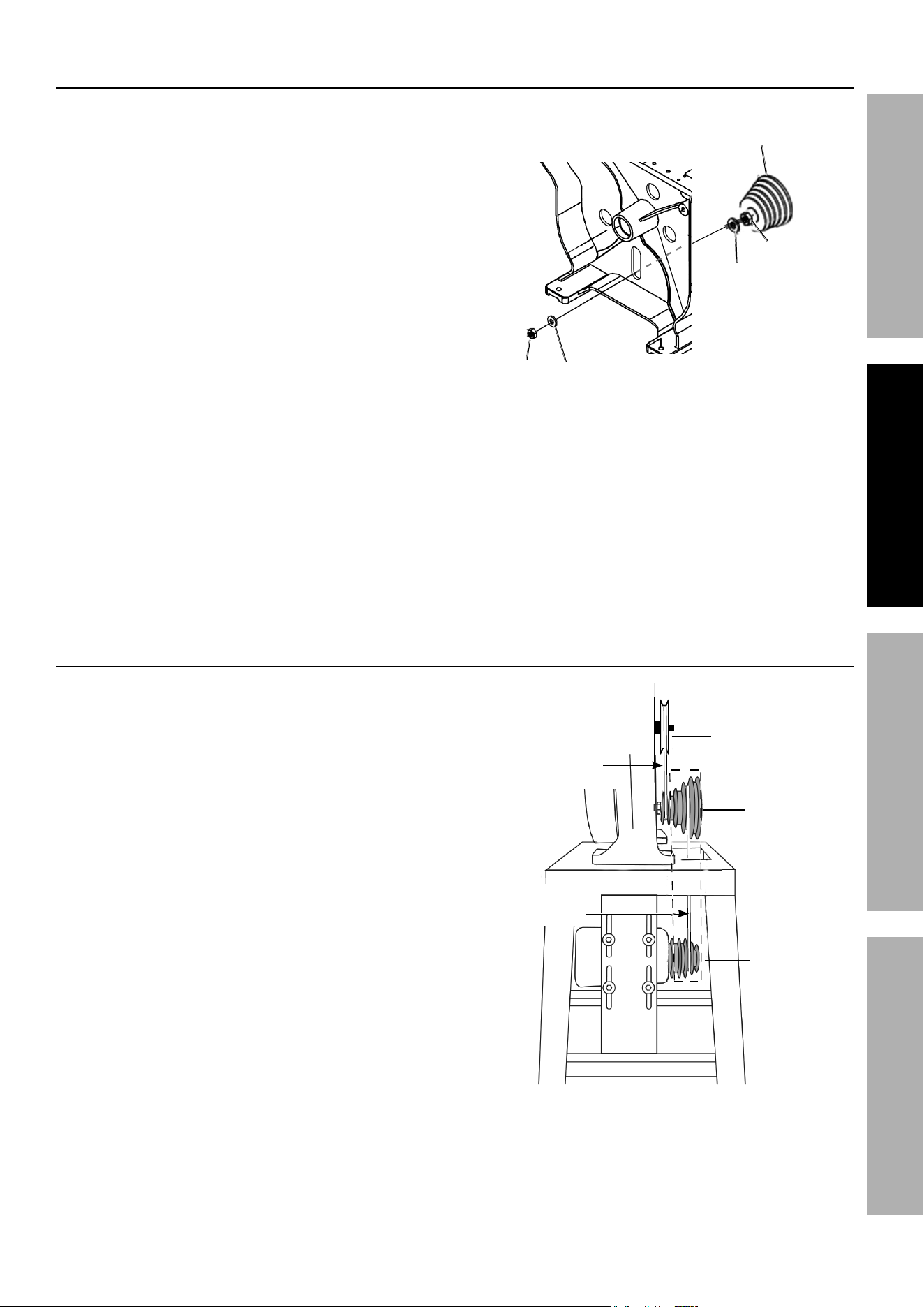
Motor to Stand assembly
- Motor Mounting
1. Have an assistant hold the Motor (10) in place
while it is attached to the Motor Plate (7).
Turn it so that the mounting slots on
the Motor face the Motor Plate.
2. Note there are two rows of slots on the Motor Plate.
See Figure 8.
3. Line the Motor Pulley up with the hole in the
table top. When the Bandsaw housing is
attached, you will line up the Saw Pulley with the
Motor Pulley below it, as seen in Figure 11.
4. Insert a Bolt (53) and Washer (58) through
each side slot from the outside to the
Motor. Secure the Motor (10) to the Motor
Plate (7) using Nuts (60), Washers (58),
and Lock Washers (57). See Figure 8.
nOte: Leave the Nuts snug, but do not tighten them
completely until you are ready to install the Saw Pulley
and line it up with the Motor Pulley, later in the assembly.
Motor (10)
Motor plate (7)
Washer (58)
Bolt (53)
nut (60)
Washer (58)
Lock Washer (57)
Motor
plate (7)
Motor (10)
Motor
pulley
Figure 8
Bandsaw Body to
Stand assembly
1. Orient the Saw Body with the Stand before lifting it.
The Pulley(s) need to align over the belt
cutout hole and the four bolt holes must
line up with the Stand mounting slots.
2. With at least one assistant, lower the Saw
Body down on the Stand’s Face Plate (1).
Make sure that the holes in the Saw Body line
up with the slots in the Stand and that the Pulley
lines up over the belt cutout hole. See Figure 9.
3. Insert the four Bolts (91A) through one
Washer (93A) each and into the holes
in the Saw Body from the top.
4. Attach each Bolt using Washer, Lock Washer (92A),
and Nut (48A). Leave the hardware only finger tight.
5. Measure to verify that the Saw Body is properly
aligned to the Stand. Make needed adjustments.
Figure 9
Washer (93a)
Lock Washer
(92a)
Bolt (91a)
nut (48a)
Face
plate (1)
Saw
pulley
(103a)
Saw
Body
Belt cutout
Hole
Washer (93a)
Stand
53
53
58
58
57
57
60
60
93a
93a
92a
92a
48a
48a
91a
91a
Page 9For technical questions, please call 1-888-866-5797.Item 60564
SaFetyOperatiOnMaintenance Setup
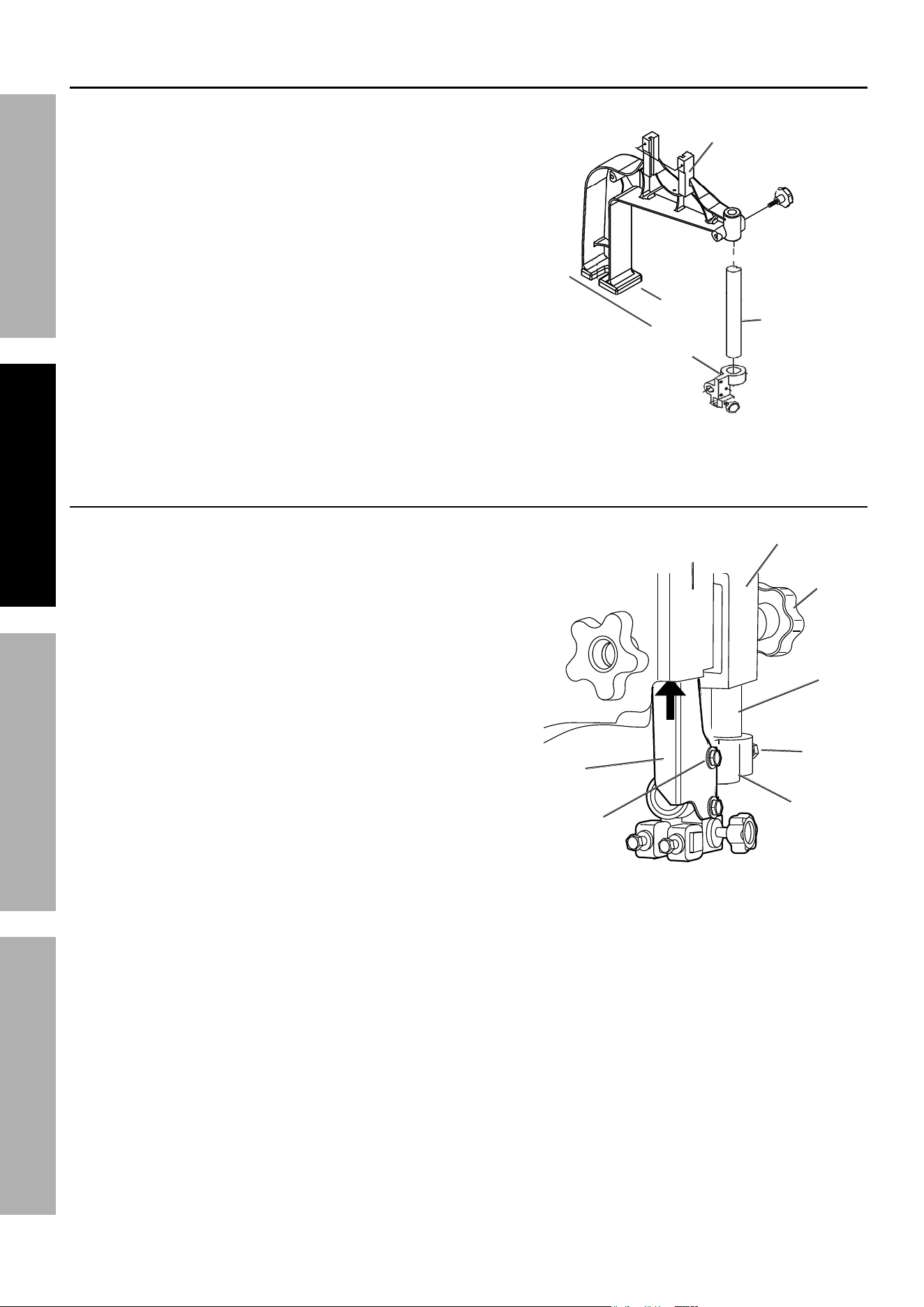
Saw pulley assembly
1. The Saw Pulley (103A) comes pre-assembled but
you need to attach it to the Saw Body Base (34A)
which is inside the Saw Body (see Figure 9).
To attach the Saw Pulley, you will temporarily
remove a few parts from the assembly.
2. Remove the outer most Nut (35A) and first Flat
Washer (33A) from the end of the Saw Pulley
assembly. Leave the Nut (35A) next to the Saw
Pulley in place and hold its Flat Washer (33A) in
place as you connect it to the Saw Base (34A).
3. While holding the Flat Washer in place, feed
the Saw Pulley′s shaft through the Saw Base′s
elongated opening as shown in Figure 10. Note
that the Upper Wheel (24A) will be in front of
the Saw Base but is not shown in Figure 10.
4. Line up the Pulleys using Figure 11 as a guide:
a. Line up the small inner most ring of the
Saw Pulley to the Top Pulley above it.
b. Line up the four outside rings of the Saw
Pulley to the Motor Pulley below it.
5. Once aligned, tighten the Pulley hardware
and also the Stand/Saw Body hardware.
Figure 10
Saw pulley
(103a)
nut (35a)
Base (34a)
Flat Washer
(33a)
nut
(35a)
Flat Washer
(33a)
Belt and pulley Orientation
1. The Top Pulley (63A) comes pre-
assembled to the Saw Body.
2. Be sure the Top Pulley aligns to the Saw
Pulley′s small inner-most ring.
3. The Saw Pulley′s four outside rings should
align with the Motor Pulley′s four rings.
4. The Bandsaw assembly kit contains two belts:
a. The Short Belt (101A) attaches from
the Top Pulley to the Saw Pulley.
b. The Long Belt (102A) attaches the
Saw Pulley to the Motor Pulley.
5. Install the belts later. See Figure 20
in ″Belt Installation″ for details.
top pulley
(63a)
Saw pulley
(103a)
Motor pulley
(103)
Long Belt
(102a)
Short Belt
(101a)
Figure 11
Page 10 For technical questions, please call 1-888-866-5797. Item 60564
SaFety OperatiOn MaintenanceSetup
Guide post assembly to Frame arm
1. The Front Arm (1A) comes
pre-assembled inside the Saw Body. You will
connect the Guide Post (4A) to the Arm.
2. Insert the Guide Post (4A) into the
Front Arm (1A) socket. Tighten Knob (6A) to
secure the Post to the Arm. See Figure 12.
3. Proceed to Upper Blade Guard
Assembly to Guide Post.
Guide
post
(4a)
Knob
(6a)
Front arm
(1a)
Bracket
post
(5-1a)
Figure 12
upper Blade Guard assembly
to Guide post
1. Assemble the Upper Blade Guard (2A) to the
Bracket Post (5-1A) using two Hex Head
Bolts (73A) and Flat Washers (74A).
2. Loosen Hex Bolt (3A) on the side of the
Bracket Post. Slide the Guide Post (4A)
into the Bracket Post (5-1A).
3. Slide the Upper Blade Guard (2A) up into
the inside of the Upper Wheel Guard (29A)
where the wheel resides. See Figure 13.
4. the end of the Guide post (4a) and
the end of the Bracket post (5-1a)
should be flush with each other.
5. Once aligned, tighten the Hex Bolt (3A) and
Knob (6A) to secure it. Do not over-tighten.
Front arm
(1a)
Knob
(6a)
upper Wheel
Guard (29a)
upper Blade
Guard (2a)
Bracket
post
(5-1a)
Hex Bolt
(3a)
Guide
post
(4a)
Hex Head Bolt (73a),
Flat Washer (74a)
Figure 13
Page 11For technical questions, please call 1-888-866-5797.Item 60564
SaFetyOperatiOnMaintenance Setup
attaching power Switch to Motor
tO preVent eLectric SHOcK anD DeatH
FrOM incOrrect GrOunDinG Wire cOnnectiOn,
reaD anD FOLLOW tHeSe inStructiOnS:
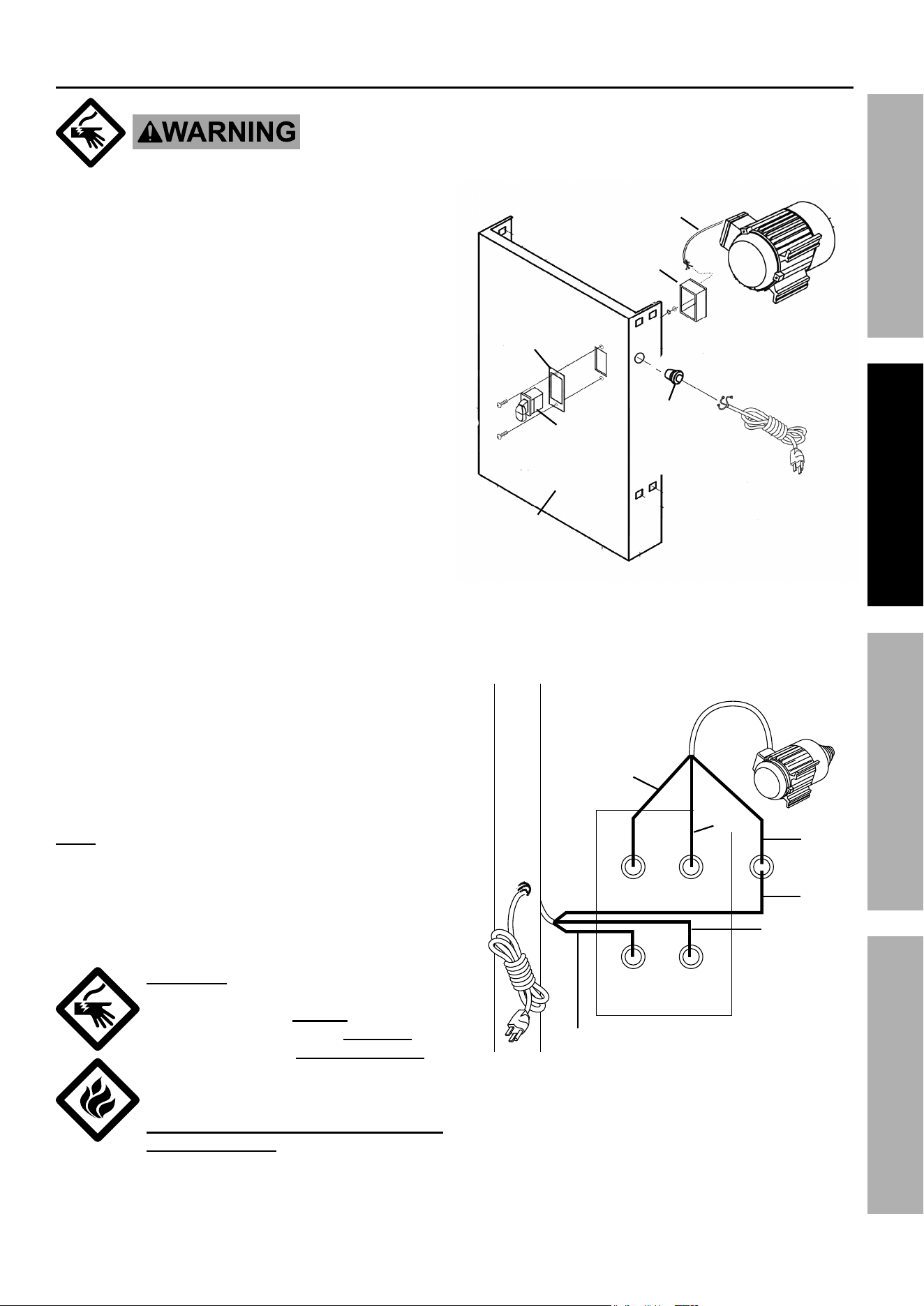
1. See Figure 14 to feed the Power Cord (20)
through the strain relief Brushing (29). Then
feed the Power Cord through the hole on
the side of the Front Leg (2). Be sure the
Power Cord wires are long enough to reach
the power switch hole plus a little slack.
2. Feed the Power Cord wires through the lower hole
on the back of the Switch Box.
Feed the green ground wire through the
small hole on the side of the Switch Box.
Position the Switch Box so that the small side
hole points away from the Power Cord.
3. Hold the Power Cord in place while pushing
the strain relief Brushing (29) into the Front
Leg side hole. Once in place, be sure Power
Cord is secure to the Front Leg panel.
4. Feed the Motor Cord wires through the upper hole
on the back of the Switch Box, and then to the back
of the Power Switch.
Feed its green ground wire through the small
hole on the side of the Switch Box,next
to the Power Cord′s green wire.
5. See Figure 15 to connect the Motor Cord and Power
Cord wires to the Power Switch.
On the Power Switch, connect the Power Cord wires
to the bottom connections (black “hot“ wire, white
“neutral” wire, and green ″ground″ wire).
Connect the Motor cord wires to the top
connections.
Be sure the wires colors line up top to bottom: Black
with black, white with white, and green with green.
note: The two green wires are attached to
the screw to the right of the Power Switch
Tighten its Nut (27) to secure in place.
6. From the inside of the Front Leg (2), attach the
Switch Box (28) to the back of the Power Switch.
Secure Switch in place using Screws (23).
WarninG! tO preVent eLectric
SHOcK, Fire anD DeatH:
it is critical that the Green ground wire
is attached to the terminal OutSiDe the
switch box and that OnLy the Green
wire is attached outside the switch box.
the included terminals are designed to
reduce the risk of improper wiring;
DO nOt MODiFy, repLace Or FOrce
tHe terMinaLS.
if you have any doubt about your ability to
connect the motor wires safely and securely,
have a certified electrician connect the wiring.
power
cord (20)
Motor
(10)
Bushing
(29)
Front
Leg (2)
power
Switch
(28)
Motor cord
power
Switch
plate (28-1)
Switch Box
(28-2)
Figure 14
Motor
(10)
Black
White
Green
Green
White
Black
power
cord (20)
power Switch
(28)
Figure 15
Page 12 For technical questions, please call 1-888-866-5797. Item 60564
SaFety OperatiOn MaintenanceSetup
table
assembly
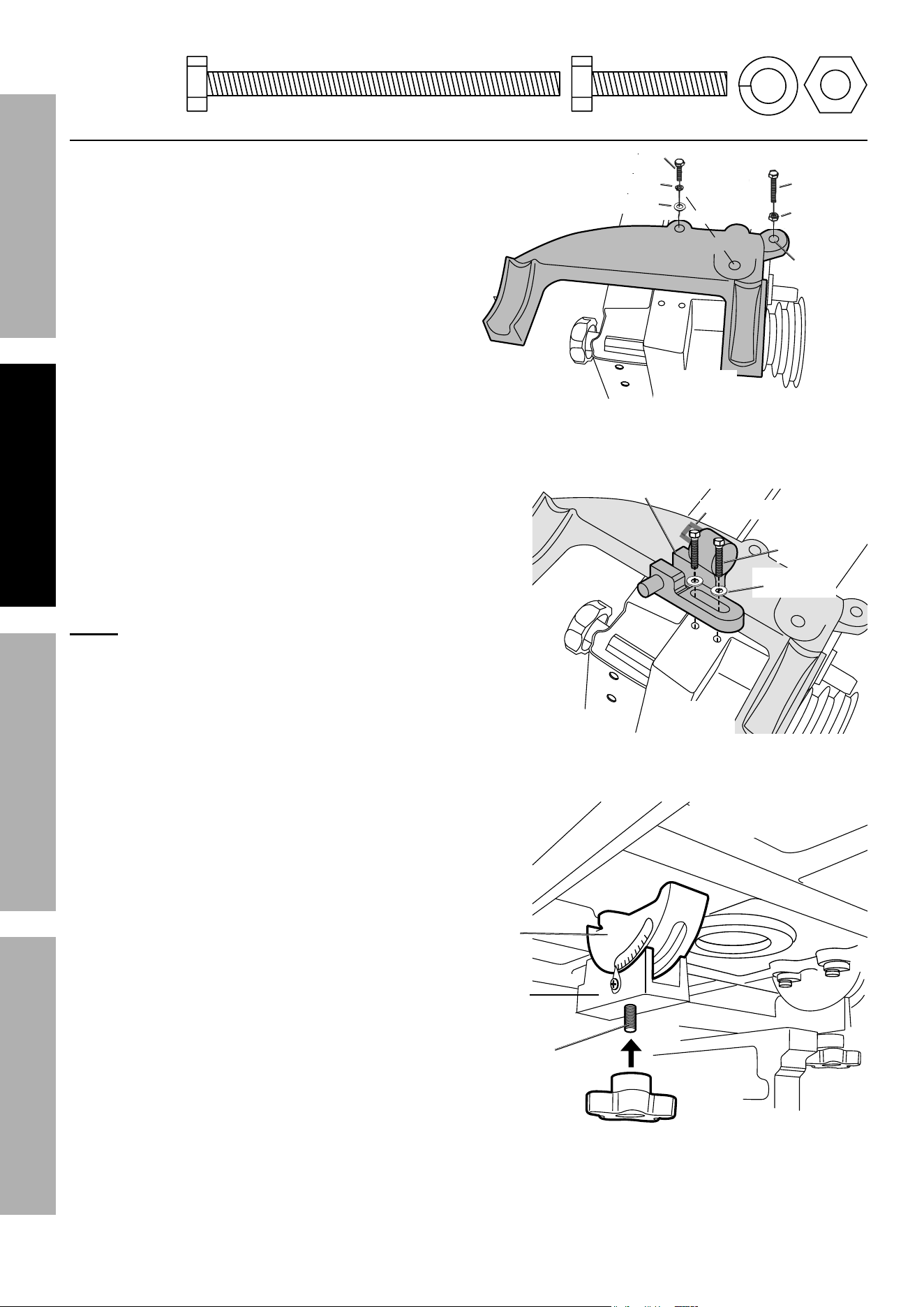
1. Set the Table Bracket (45A) onto the Saw Body
Base (34A) as shown in Figure 16. Note that the
Table Bracket has a Stop Bolt Hole which should be
on the same side as the Pulley.
Also, the Saw Body Base has two
threaded holes for two Bolts (91A).
2. Secure the Table Bracket to the Saw Body Base
using two Bolts (91A), Spring Washers (92A), and
Flat Washers (93A). Tighten securely in place.
3. Thread the Nut (48A) all the way to the head
of Bolt (47A). Install the Bolt with Nut into the
Table Stop Bolt Hole noted in Figure 16.
4. Attach the Bracket Post (55A) with Bearing (9A)
to the Saw Body Base (34A) next to the Table
Bracket. Secure in place with two Hex Bolts (53A)
and Flat Washers (54A) , as shown in Figure 17.
nOte: The hardware for this step is packaged
separately from the hardware bag.
5. Locate the Table Bracket (45A). Note that
there are two Bolts (40-1A) extending out
from the bottom of the two Trunnions (42A).
Insert those two Bolts through the holes in
the Table Bracket and secure the Bolts in
place using Knobs (46A). See Figure 18.
nut (48a)
Bolt (47a)
Flat Washer (93a)
Spring Washer (92a)
table Bracket (45a)
table Stop
Bolt Hole
Bolt (91a)
Saw Body
Base (34a)
Figure 16
Bolt (53a)
Flat Washer
(54a)
Saw Body
Base (34)
Bracket
post (55a)
Bearing (9a)
Figure 17
Figure 18
Knob
(46a)
trunnion
(42a)
table
Bracket (45a)
Bolt (40-1a)
under the
table (39a)
47a
47a
91a
91a
92a
92a
48a
48a
Page 13For technical questions, please call 1-888-866-5797.Item 60564
SaFetyOperatiOnMaintenance Setup
pulley cover Door assembly
and Belt installation
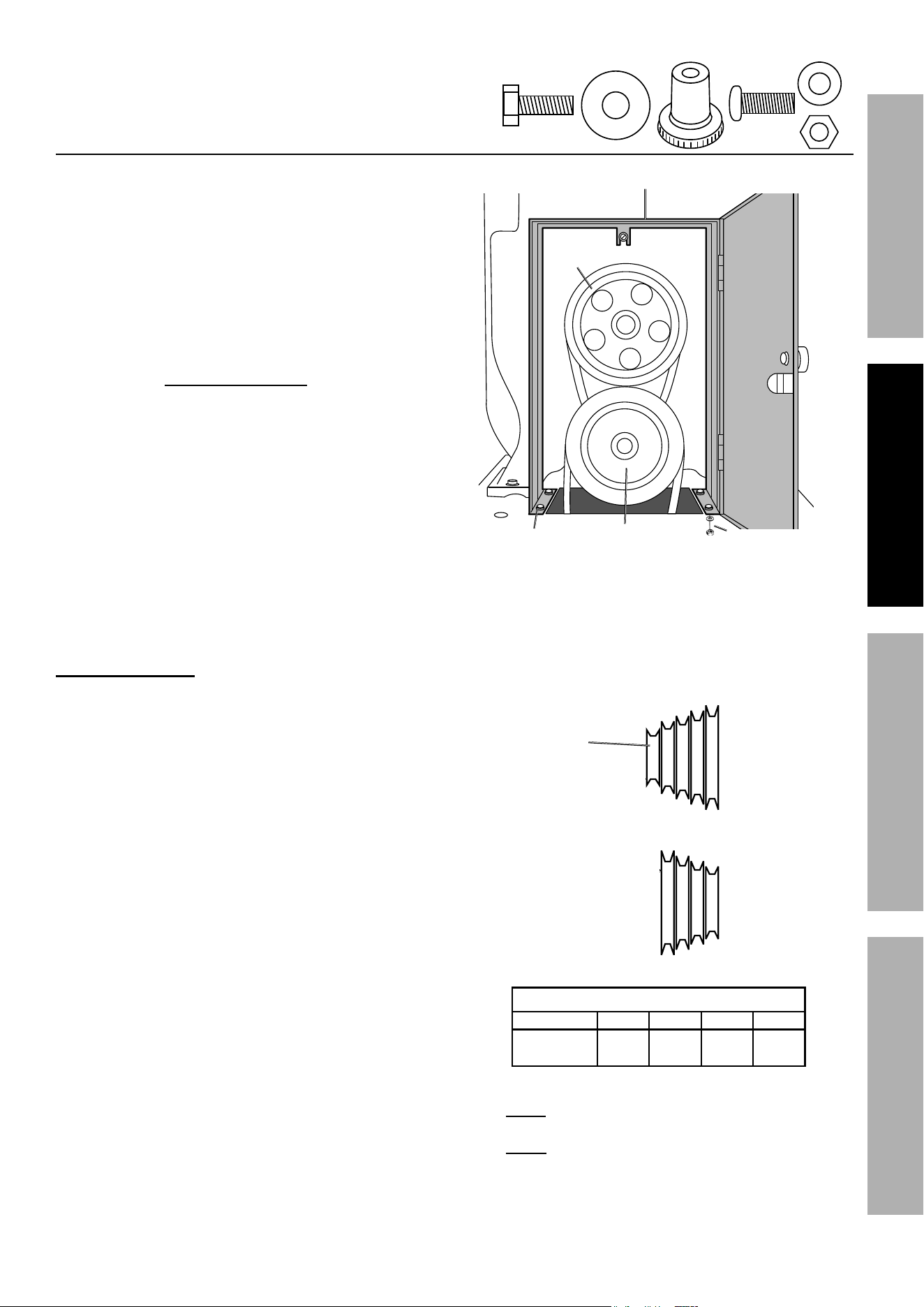
1. Once the belts are installed, set the Pulley Box (11)
over the Top Pulley (63A) and Saw Pulley (103A)
with the door opening to the outside. See Figure 19.
2. Insert a Pan Head Bolt (62) through a Washer (56)
and into each of the four holes at the bottom of the
Pulley Box. Secure the Bolts (62) from underneath
using one Washer (56) and Nut (61) each.
3. Secure the Knob (63) to the door using
Bolt (54) and Washer (59) from the
other side. Do not overtighten.
4. Close the Pulley Box door to make sure
it closes completely and securely.
Knob
(63)
pulley Box (11)
top pully
(63a)
Saw pulley
(103a)
pan Head
Bolt (62),
Washer (56)
Washer (56),
nut (61)
Figure 19
Belt installation
5. Slide the Motor up towards the top of its
rail to allow easy belt installation.
6. Using the chart ″Pulley Speed Settings″ to the right,
choose which speed you would like the Saw Blade
(36A) to operate at initially. Slide Long Belt (102A)
onto the desired Motor Pulley (12) position. Then
slide the Belt up over the Saw Pulley (103A) in
the same numbered position. See Figure 20.
7. To set Belt tension, have an assistant pull down
on the Motor and hold it in place to put tension
on the Belt. Then test the belt’s tension by gently
pushing in on it in between pulleys. If it only
deflects about 1/2″ to 3/4″ from straight, then the
belt is properly tensioned at that motor position.
While the assistant holds the motor at that
position, secure the motor in place by tightening
the previously loosened Bolts and nuts.
8. after tightening, verify that all pulleys
and belts are still aligned and their
connecting hardware is secure.
this position
is for the
short belt
to the top
pulley.
1
2
3
4
1
2
3
4
3D
3D
1D
1D
Motor pulley
(12)
Saw pulley
(103a)
Figure 20
pulley Speed Settings
position 1 2 3 4
Output
FpM
568 1080 1582 2529
note: The small unnumbered inner-most
position on the Saw Pulley (103A) should
ONLY be used to drive the Top Pulley (63A),
and should not be used to change speeds.
54
59
63
62
56
61
Page 14 For technical questions, please call 1-888-866-5797. Item 60564
SaFety OperatiOn MaintenanceSetup
Side panel installation
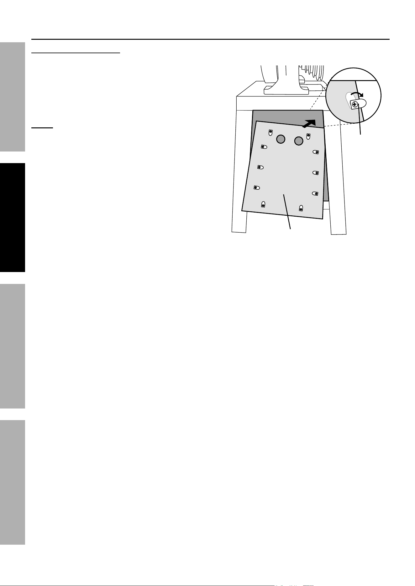
9. Attach the Press Blocks to the textured side of
the Side Panel (66) by screwing the Screws into
the mounting holes on the Side Panel. Leave
the Screws (68) just loose enough to allow
the Press Blocks to turn. See Figure 21.
nOte: Do not overtighten - use a screwdriver
when tightening.
10. Position the Press Blocks so that they
point towards the center of the Side Panel.
See Figure 21.
11. While holding the Side Panel by the two finger
holes, place it inside the side of the Stand as
shown in Figure 21. Rotate the Press Blocks out
and tighten the Screws (68) to secure the Side
Panel in place. Repeat for the other Side Panel.
press
Block (67)
Side panel
(66)
Figure 21
pulley cover assembly and Belt installation (continued)
Page 15For technical questions, please call 1-888-866-5797.Item 60564
SaFetyOperatiOnMaintenance Setup
Operating instructions
read the entire iMpOrtant SaFety inFOrMatiOn section at the beginning of this
manual including all text under subheadings therein before set up or use of this product.
tool Set up
tO preVent SeriOuS inJury FrOM acciDentaL OperatiOn:
turn the power Switch of the tool to its “OFF” position and unplug the tool from its
electrical outlet before assembling or making any adjustments to the tool.
tO preVent SeriOuS inJury:
DO nOt Operate WitH any GuarD DiSaBLeD, DaMaGeD, Or reMOVeD.
Saw Blade installation
1. Fully open the Upper Wheel Guard (29A) and
the Lower Wheel Guard (69A). These guards
are next to the wheels inside the Saw Body.
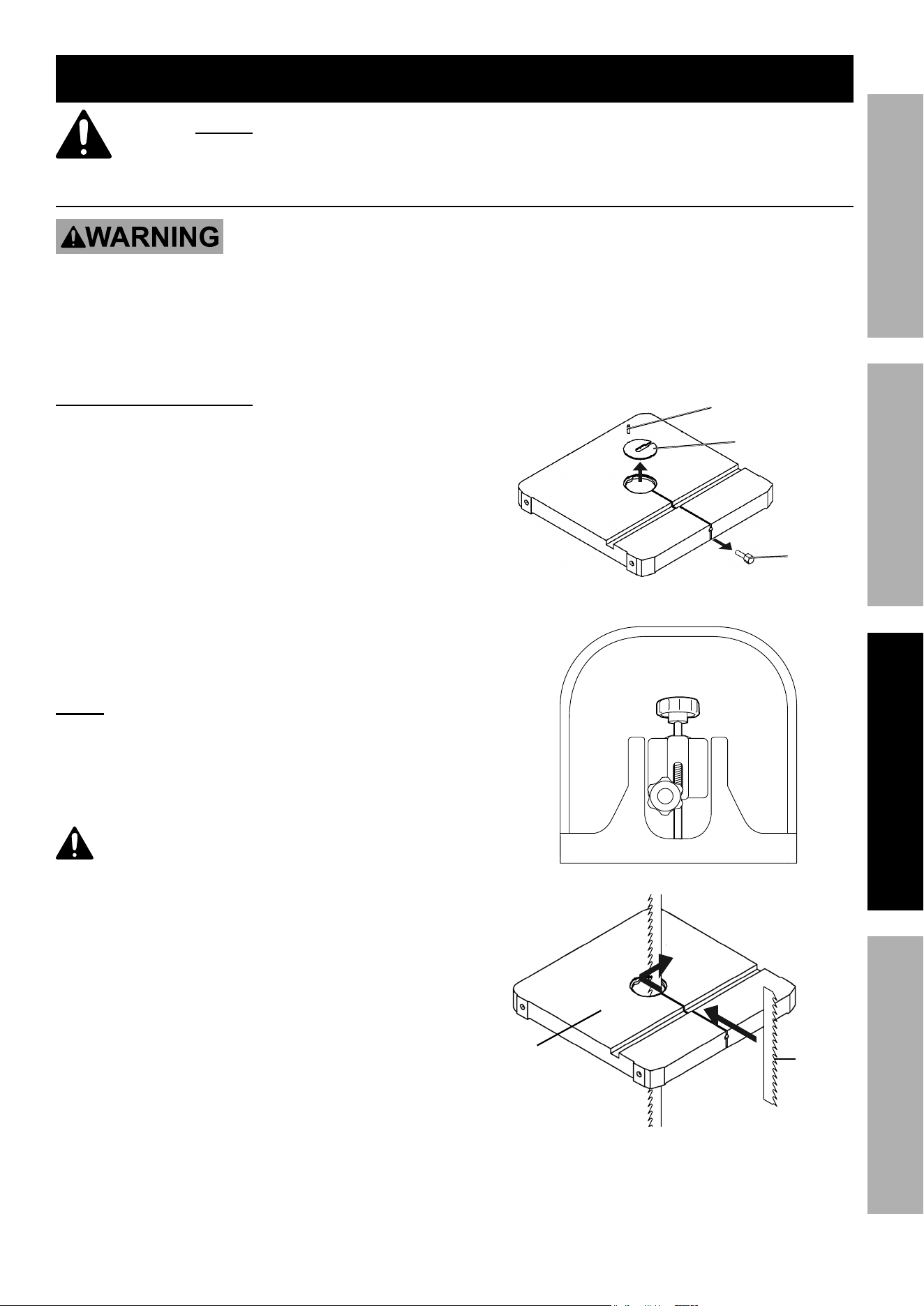
2. Remove the Table Insert (37A) and
Table Pin (38A). See Figure 22. Save the parts.
3. Turn the Blade Adjusting Knob (14A)
counterclockwise 5-10 full turns. See Figure 23.
nOte: If the Blade Guard (70A) on the back of
the Upper Wheel Guard is installed, it must be
removed prior to blade installation. See Figure 23
for location of the Blade Guard (70A).
cautiOn! take extreme caution when
unraveling the blade. the blade teeth are very
sharp. Wear anSi-approved safety goggles and
gloves when handling the blade and hold it away
from your body.
4. With both hands, hold the Saw Blade with its teeth
pointing downward and away from your body.
Then insert one side of the Saw Blade (36A)
back side first and through the slot in
the Table (39A). See Figure 24.
Spring pin
(37-1a)
table insert
(37a)
table pin
(38a)
Figure 22
Blade adjusting
Knob (14a)
Figure 23
table
(39a)
Saw
Blade
(36a)
Figure 24
Page 16 For technical questions, please call 1-888-866-5797. Item 60564
SaFety OperatiOn MaintenanceSetup
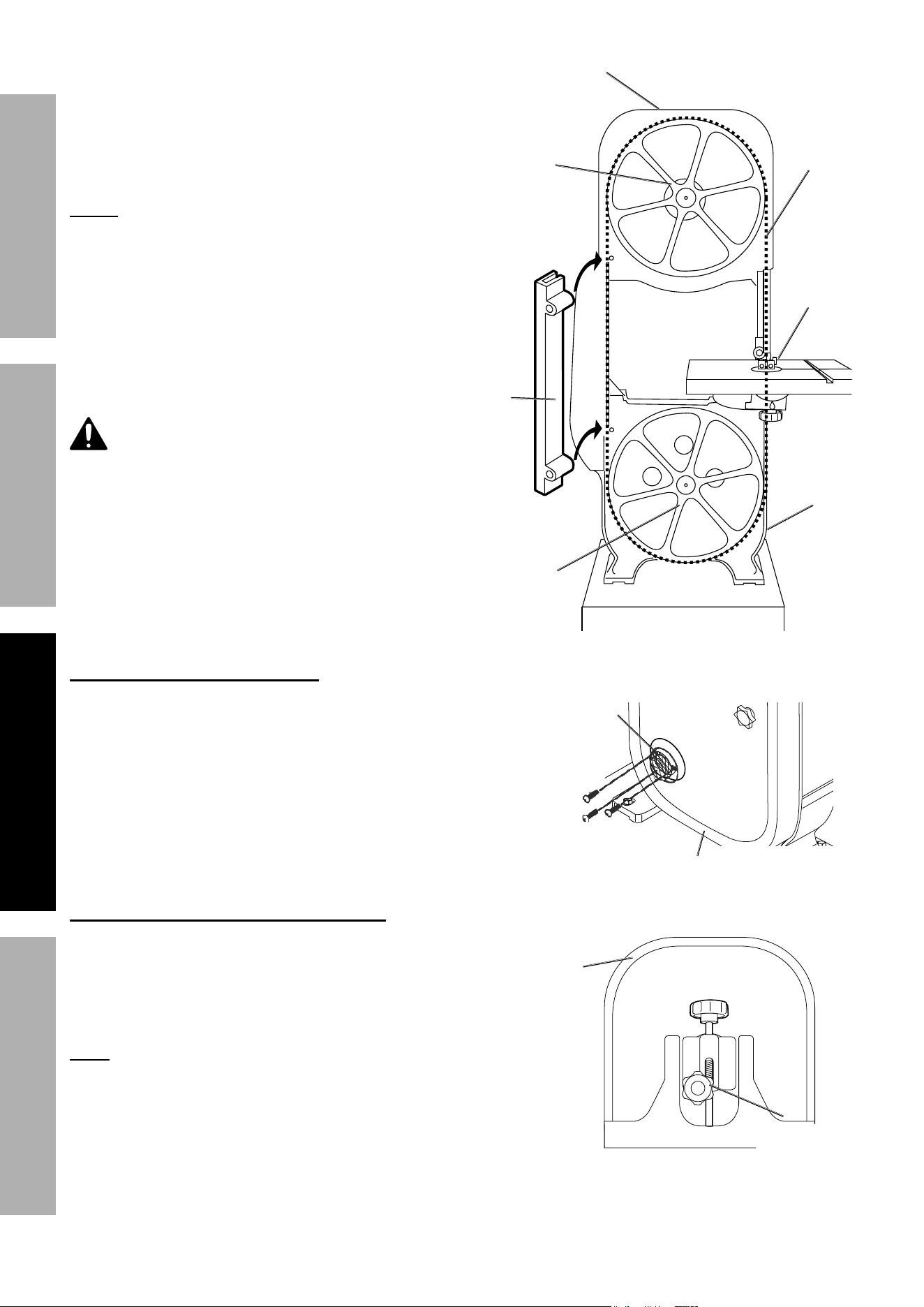
5. Place the Saw Blade (36A) through the
upper Blade Guides (11A) and over the
Upper Wheel (24A). See Figure 25
6. Place the Saw Blade (36A) on the
Lower Wheel (67A) and through the lower
Blade Guides (11-1A), under the table.
nOte: If the blade is too tight for positioning, turn
the Blade Adjusting Knob (14A) counter-clockwise to
loosen just enough to get the blade onto the upper and
lower wheels. See Figure 27 for location of the knob.
7. Replace the saved Table Insert (37A)
and Table Pin (38A), see Figure 24.
8. Place the Blade Guard (70A) onto the two Studs
and over the Saw Blade. See Figure 25.
WarninG! to prevent serious injury, place
both Blade Guards (69a and 29a) over the Saw
Blade and secure them BeFOre operation.
Figure 25
upper
Wheel
Guard (29a)
Lower
Wheel
Guard (69a)
Blade
Guide
(11a)
Saw
Blade
(36a)
upper
Wheel
(24a)
Lower
Wheel
(67a)
Blade
Guard
(70a)
Dust chute Setup (Optional)
If you wish to attach a dust collector to your Bandsaw,
attach the Dust Port (94A) to the Lower Wheel
Guard (69A) using Screws (95A). See Figure 26.
Dust port
(94a)
Lower Wheel
Guard (69a)
Screws
(95a)
Figure 26
Saw Blade tensioning and tracking
The Saw Blade tension is adjusted using
the Blade Adjusting Knob (14A) on the back
of the Inner Wheel Guard (28A). Turn the
Knob clockwise to increase tension and
counter-clockwise to decrease tension.
note: Too much tension is a common
cause of Saw Blade breakage and other
unsatisfactory performance. Relieve the
tension when the Bandsaw is not in use.
9. Adjust Upper and Lower Blade Guides so that they
do not contact the blade during tracking adjustment.
10. To adjust tracking placement of the blade on the
wheel, loosen the nut on Blade Tracking Knob (18A).
inner Wheel
Guard (28a)
Blade adjusting
Knob (14a)
Blade tracking
Knob (18a)
Figure 27
Page 17For technical questions, please call 1-888-866-5797.Item 60564
SaFetyOperatiOnMaintenance Setup
Saw Blade tensioning and tracking (continued)
11. WarninG! to prevent serious injury;
adjust blade tracking only with the Bandsaw off
and power cord unplugged. Wear gloves.
Slowly turn the Upper and Lower Wheels clockwise
by gloved hand and watch the Saw Blade to see
whether it travels in the center of the Upper
Wheel. If it does not, adjust the tracking as follows:
• If the Saw Blade begins to creep toward the
front edge of the Upper Wheel, turn the Blade
Tracking Knob clockwise 1/4 turn to draw the
Saw Blade toward the back of the Upper Wheel.
• If the Saw Blade begins to creep toward
the back edge of the Upper Wheel, turn
the Blade Tracking Knob counterclockwise
1/4 turn to draw the Saw Blade toward
the front of the Upper Wheel.
12. If any tracking adjustments were made, repeat
the previous until the Blade stays centered on
the Upper Wheel for at least 5 turns or so.
13. Once alignment is achieved, tighten the nut
on the shaft of the Blade tracking Knob
(18a), locking the tracking in place.
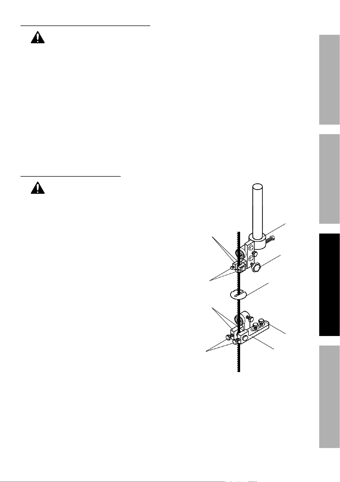
Guide and Bearing adjustment
1. WarninG! tO preVent SeriOuS
inJury: Only adjust guides and bearings after
blade tension and tracking is properly adjusted.
2. Loosen Hex Bolts (10A) on the Bracket
Post (5-1A) and make sure that the Bracket
Post is aligned with the Saw Blade.
3. Loosen the Knob Screw (56-1A) on the side
of the Bracket Post and adjust the upper
Blade Guides′ (11) position so that they line up with
the flat portion of the Saw Blade without reaching
the cutting edge. See Figure 28.
Tighten the Knob Screw (56-1A) after adjustment.
4. Loosen two Hex Bolts (10A) and move the
upper Blade Guides (11) as close as possible
to the side of the Saw Blade without touching
it. Once aligned, tighten the Hex Bolts.
5. Loosen the two Angle Knobs (46A) under
the Table and pivot the Table forward
as far as possible. See Figure 30.
6. Loosen the two Hex Bolts (53A) on the
Bracket Post (55A) and adjust the lower Blade
Guides’ (11A) positions so that they line up
with the flat portion of the Saw Blade without
reaching the cutting edge. See Figure 28.
Tighten the Hex Bolts (53A) after adjustment.
7. Pivot the Table backward as far as possible.
8. Loosen the two Front Hex Bolts and move the
lower Blade Guides (11A) as close as possible
to the side of the Saw Blade without touching it.
Once aligned, tighten the Front Hex Bolts.
9. Return Table to its normal position and secure
by tightening Knobs (46A). See Figure 30.
Hex
Bolt
(53a)
upper
Bracket
post
(5-1a)
Knob
Screw
(56-1a)
Blade
Guide (11a)
table
insert
(37a)
Hex
Bolt 10a)
Blade
Guide
(11-1a)
table
Bracket
post
(55a)
Front
Hex
Bolt
Figure 28
Page 18 For technical questions, please call 1-888-866-5797. Item 60564
SaFety OperatiOn MaintenanceSetup
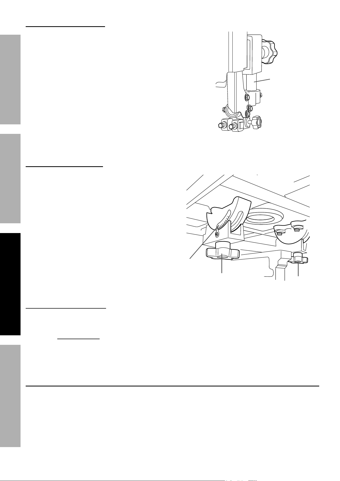
Blade Guide adjustment
1. Loosen the Knob (6A) and set the
Bracket Post (5-1A) as close as possible to the top
surface of the material being cut. See Figure 29.
2. Once the Bracket Post is adjusted,
securely tighten the Knob (6A).
Knob
(6a)
Bracket
post
(5-1a)
Figure 29
table angle adjustment
1. Loosen the two Angle Knobs (46A) underneath
the Table (39A). See Figure 30.
2. Tilt the Table to the left or right until the
needle points are set to the desired angle
on the Scale (51A). Once properly adjusted,
securely tighten both Angle Knobs (46A).
Figure 30
under the
table (39a)
angle Knob
(46a)
angle Knob
(46a)
Scale
(51a)
Blade Speed adjustment
1. Remove the Side Panel and open
the Pulley Box to allow access.
2. Use the Belt installation instructions
on page 13 to change the Belt’s position
to the desired speed setting.
3. Replace the Side Panel and close the
Pulley Box after changing the speed setting.
Work piece and area Setup
1. Designate a work area that is clean and well-lit.
The work area must not allow access by children
or pets to prevent distraction and injury.
2. Route the power cord along a safe route to reach
the work area without creating a tripping hazard or
exposing the power cord to possible damage. The
power cord must reach the work area with enough
extra length to allow free movement while working.
3. Secure loose work pieces using a vise or clamps
(not included) to prevent movement while working.
4. There must not be objects, such as utility lines,
nearby that will present a hazard while working.
5. Keep ANSI-approved safety goggles
and work gloves nearby.
Page 19For technical questions, please call 1-888-866-5797.Item 60564
SaFetyOperatiOnMaintenance Setup
General Operating instructions
1. Before starting the Bandsaw make sure all
adjustments are properly made, and all of
the guards and covers are in place.
2. Make sure you know how to turn the Bandsaw
off before powering on. To turn the Bandsaw
off, push the Power Switch down
3. Before turning on the power, make sure that
nothing is obstructing the Saw Blade (36).
4. Keep the Bracket Post (5-1A) down, as close
as possible to the material being cut.
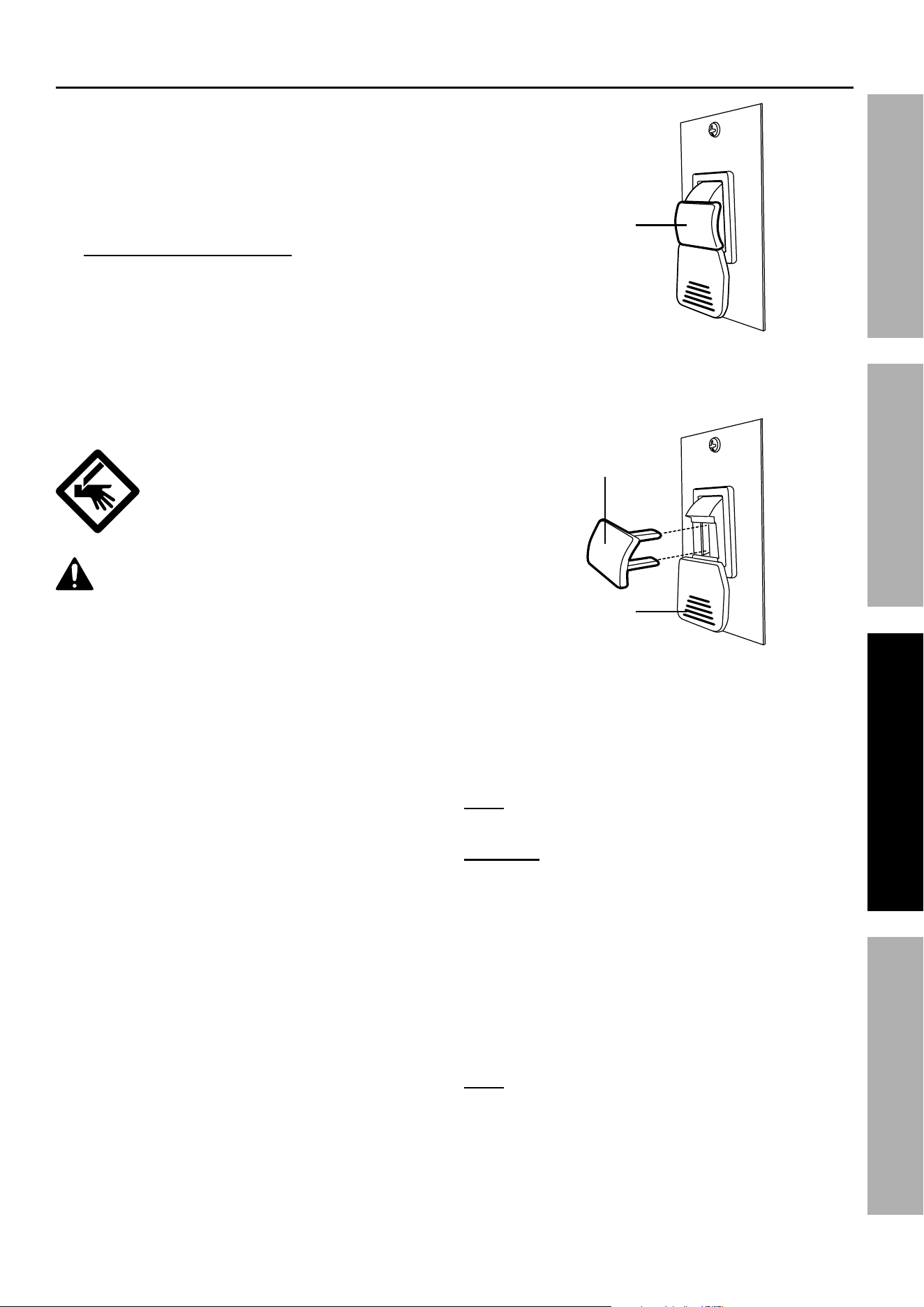
5. To turn on the Bandsaw, insert the Key,
then pull the Switch up, see Figure 31.
6. To turn off the Bandsaw, push the Key
down and remove it, see Figure 32.
WarninG! tO preVent
SeriOuS inJury anD
aMputatiOn: Keep hands out
of cut line of blade at all times.
cautiOn! Wear anSi-approved safety
goggles.
7. Allow the Bandsaw to reach its full
speed before cutting the material.
8. Do not force the material into the Saw
Blade (36). Light contact with the Saw Blade
will permit easier following of the line and
prevent undue friction, heating and work-
hardening of the Saw Blade at its back edge.
9. Keep the Saw Blade sharp for easier
forward pressure when cutting.
10. Move the material slowly and steadily
against the Saw Blade.
11. Avoid twisting the Saw Blade when attempting
to turn sharp corners. Remember to slowly
cut around the outside of corners.
12. When cutting curves, turn the material
carefully so that the Saw Blade can
follow the line without being twisted.
13. If a curve is so abrupt that it is necessary
to repeatedly back up and cut a new kerf, a
more narrow Saw Blade should be used.
Key
engaged
Key
power
Switch
Figure 31
Figure 32
14. After use, turn off Bandsaw, remove
Switch Key, unplug the power cord
and allow the Bandsaw to cool.
note: After every use, clean away all particles
that have accumulated around the Bandsaw.
cautiOn! tO preVent Fire:
Do not allow sawdust to accumulate inside the
Bandsaw. After every use, when the Bandsaw
is off and cool, clean out the sawdust:
a. Wear heavy-duty gloves, ANSI-
approved safety goggles and NIOSH-
approved dust mask/respirator.
b. Open the Lower Wheel Guard (69A).
c. Clean the sawdust out with a brush or vacuum.
d. Close the Lower Wheel Guard.
note: A dust collector may reduce the need
for cleaning the Bandsaw interior if used.

Page 20 For technical questions, please call 1-888-866-5797. Item 60564
SaFety OperatiOn MaintenanceSetup
Maintenance and Servicing
procedures not specifically explained in this manual must
be performed only by a qualified technician.
tO preVent SeriOuS inJury FrOM acciDentaL OperatiOn:
turn the power Switch of the tool to its “OFF” position and unplug the tool from its electrical
outlet before performing any inspection, maintenance, or cleaning procedures.
tO preVent SeriOuS inJury FrOM tOOL FaiLure:
Do not use damaged equipment. if abnormal noise or vibration
occurs, have the problem corrected before further use.
cleaning, Maintenance, and Lubrication
1. BeFOre eacH uSe, inspect the general
condition of the tool. Check for:
• loose hardware or parts,
• misalignment or binding of moving parts,
• cracked or broken parts,
• damaged electrical wiring, and
• any other condition that may
affect its safe operation.
2. DO nOt intrODuce Water intO
tHe eLectric MOtOr tHrOuGH
tHe MOtOr VentS.
3. Do not use solvents to wipe off the
Bandsaw, as damage may result.
4. With a brush or soft cloth, remove all the sawdust
from within the Lower Wheel Guard of the Bandsaw.
5. If necessary, wipe with a damp cloth. A
mild detergent can also be used.
6. Once clean, lubricate all moving parts with a light oil.
7. WarninG! tO preVent SeriOuS
inJury: if the supply cord of this tool
is damaged, it must be replaced only
by a qualified service technician.
8. Store the Bandsaw covered with a cloth cover.
Page 21For technical questions, please call 1-888-866-5797.Item 60564
SaFetyOperatiOnMaintenance Setup
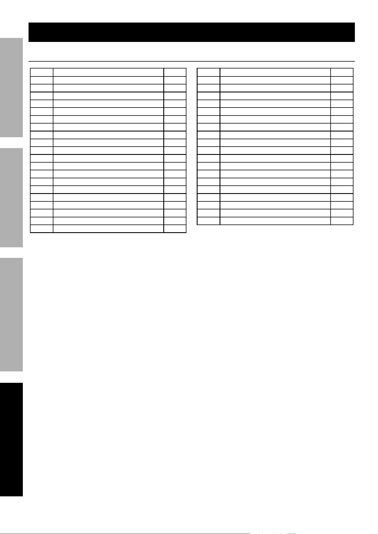
troubleshooting
problem possible causes probable Solutions
Bandsaw will not start. 1. No power at outlet.
2. Loose, or damaged electrical
connections or wiring.
1. Check power at outlet and
at circuit breakers.
2. Check all wiring and connections. Tighten
all connections. If damaged wiring is found,
replace it. DO NOT repair damaged wiring.
Bandsaw blade does
not move although
motor is running.
1. Blade tension knob is not tight.
2. Blade has slipped off wheel or
belt has slipped off pulley.
3. Blade/belt is broken.
1. Turn motor off.
Adjust tension and restart Bandsaw.
2. With Bandsaw off, open
Pulley Box and check.
3. Replace blade/belt.
Cuts are not straight 1. Work not square with Table.
2. Dull Blade.
3. Blade Guide Assembly loose.
1. Use Miter Gauge; check table angle
(page 18) and adjust tilt of head at 90°.
2. Replace Blade.
3. Tighten Blade Guide.
Blade will not cut
or cuts slowly.
1. Teeth have been dulled by contact
with hardened steel or long usage.
2. Speed setting too low.
3. Blade mounted on backwards.
1. Replace blade.
2. Use higher speed setting. See
Belt installation, page 13.
3. Remove blade and mount correctly.
Blade dulling too rapidly. 1. Blade is too coarse.
2. Hard spots on material.
3. Blade installed backwards.
1. Use a finer tooth Blade.
2. Increase pressure more gently
on object being cut.
3. Remove Blade and turn inside
out before reinstalling.
Motor running too hot. 1. Blade too coarse or too
fine for workpiece.
2. Excessive dirt, chips and sawdust
have accumulated around
Wheels and/or Saw Blade.
1. Use Blade with correct pitch.
2. Clean the Bandsaw thoroughly.
Frequent Saw
Blade Breakage.
1. Blade is too coarse for
workpiece being cut.
2. Guides/Guards are misaligned.
3. Possible Blade Weld Cracking.
1. Use a Saw Blade with a finer pitch.
2. Adjust the Guides/Guards as noted
on pages 16-18 of this manual.
3. Replace the Saw Blade.
Workpiece cuts
appear rough.
1. Workpiece being fed into
Saw Blade too fast.
2. Blade is too coarse for
material being cut.
1. Slow down the speed at which you are
feeding material through the blade.
2. Replace the blade and use
one with a finer pitch.
Page 22 For technical questions, please call 1-888-866-5797. Item 60564
SaFety OperatiOn MaintenanceSetup
part Description Qty
1 Face Plate 1
2 Front Stand Leg 1
3 Rear Stand Leg 1
4 Supporting Plate 2
5
Connecting Plate
1
6 Base Plate 1
7 Motor Plate 1
9 Inner Plate 1
10 Motor 1
10-1 Key 1
11 Pulley Box 1
12 Motor Pulley 1
13 Set Screw 1
20 Power Cord 1
21 Wire 1
23 Screw 2
24 Grounding Label screw 1
25 Washer 2
26 Lock Washer 1
27 Nut 1
part Description Qty
28 Switch 1
28-1 Switch Plate 1
28-2 Switch Box 1
29 Bushing 1
53 Hex Bolt 8
54 Hex Bolt 2
55 Carriage Bolt 28
56 Flat Washer 9
57 Spring Washer 4
58 Flat Washer 40
60 Nut 36
62 Screw 5
63 Knob 1
64 Fixed Plate 4
65 Pad 4
65-1 Feet 4
66 Side Panel 2
67 Press Block 20
68 Screw 20
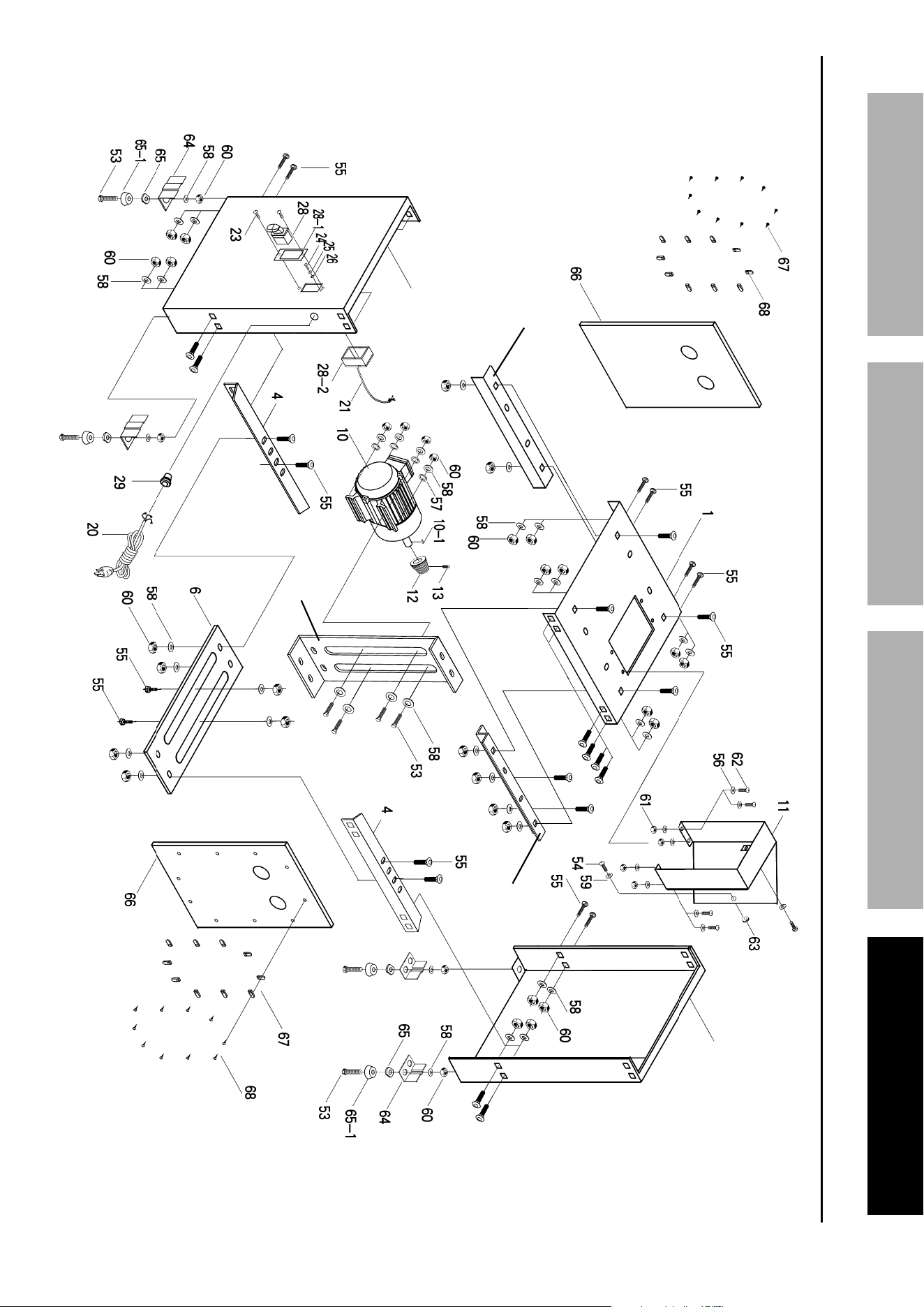
parts Lists and Diagrams
Bandsaw Stand parts List
Page 23For technical questions, please call 1-888-866-5797.Item 60564
SaFetyOperatiOnMaintenance Setup
Bandsaw Stand assembly Diagram
7
5
2
3
9
Page 24 For technical questions, please call 1-888-866-5797. Item 60564
SaFety OperatiOn MaintenanceSetup
part Description Qty
1A Frame arm 1
2A Blade guard 1
3A Hex bolt 2
4A Guide post 1
5-1A Bracket post 1
5-2A Guide bracket 1
6A Knob 1
7A Spacing sleeve 1
8A Retaining ring 3
9A Bearing (6200zz) 2
10A Hex bolt 4
11A Blade guide 2
11-1A Blade guide 2
12A Retaining ring 3
13A Screw 2
14A Blade adjusting knob 1
15A Coil spring 1
16A Wheel bracket 1
17A Square nut 1
18A Blade tracking knob 1
19A Wheel shaft hinge 1
20A Spring pin 1
21A Steel pin 2
22A Wheel shaft 1
23A Bearing (6202z) 4
24A Upper wheel 1
25A Wheel protector 2
26A Nut 1
27A Stud 4
28A Inner wheel guard 1
29A Upper wheel guard 1
30A Knob nut 4
31A Spring pin 4
32A Hex bolt 1
33A Flat washer 4
34A Base 1
35A Nut 3
36A Saw blade 1
37A Table insert 1
37-1A Spring pin 1
38A Table pin 1
39A Table 1
40-1A Bolt 2
41A Trunnion clamp 2
42A Trunnion 2
43A Flat washer 6
44A Hex Bolt 6
part Description Qty
45A Table bracket 1
46A Angle Knob 2
47A Hex bolt 1
48A Nut 6
49A Pointer rod 1
50A Screw 1
51A Scale 1
52A Side cover 1
53A Hex Bolt 2
54A Flat washer 2
55A Bracket post 1
56-1A Knob screw 1
56-2A Knob screw 1
58A Blade guide 1
61A Key 2
63A Top Pulley 1
64A Retaining ring 1
65A Lower wheel shaft 1
66A Bearing (6204z) 2
67A Lower wheel 1
68A Nut 1
69A Lower wheel guard 1
70A Blade guard 1
73A Hex bolt 2
74A Flat washer 2
82A Scale 1
83A Guide plate 1
84A Pointer 1
87A Screw 1
89A Knob 1
90A Flat washer 1
91A Hex bolt 6
92A Spring washer 6
93A Flat washer 10
94A Dust port 1
95A Screw 3
96A Nut 3
97A Flat washer 4
98A Flat washer 2
99A Bushing 1
100A Set Screw 2
101A Belt 1
102A Belt 1
103A Saw pulley 1
104A Retaining ring 2
105A Shaft 1
Bandsaw parts List
Page 25For technical questions, please call 1-888-866-5797.Item 60564
SaFetyOperatiOnMaintenance Setup
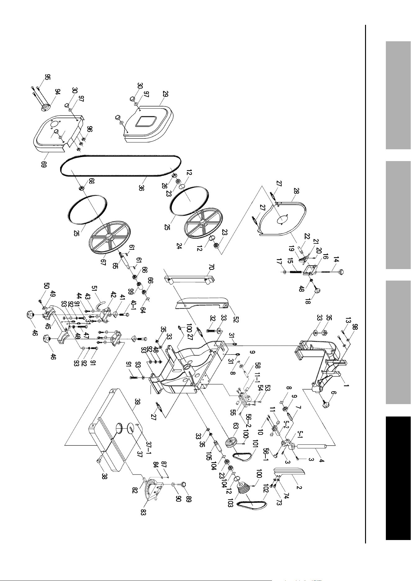
Bandsaw assembly Diagram
Please Note: Add an "A"
suffix to each part number
on this Parts Diagram to
correspond with Parts List.
34

Page 26 For technical questions, please call 1-888-866-5797. Item 60564
SaFety OperatiOn MaintenanceSetup
pLeaSe reaD tHe FOLLOWinG careFuLLy
THE MANUFACTURER AND/OR DISTRIBUTOR HAS PROVIDED THE PARTS LIST AND ASSEMBLY DIAGRAM
IN THIS MANUAL AS A REFERENCE TOOL ONLY. NEITHER THE MANUFACTURER OR DISTRIBUTOR
MAKES ANY REPRESENTATION OR WARRANTY OF ANY KIND TO THE BUYER THAT HE OR SHE IS
QUALIFIED TO MAKE ANY REPAIRS TO THE PRODUCT, OR THAT HE OR SHE IS QUALIFIED TO REPLACE
ANY PARTS OF THE PRODUCT. IN FACT, THE MANUFACTURER AND/OR DISTRIBUTOR EXPRESSLY
STATES THAT ALL REPAIRS AND PARTS REPLACEMENTS SHOULD BE UNDERTAKEN BY CERTIFIED AND
LICENSED TECHNICIANS, AND NOT BY THE BUYER. THE BUYER ASSUMES ALL RISK AND LIABILITY
ARISING OUT OF HIS OR HER REPAIRS TO THE ORIGINAL PRODUCT OR REPLACEMENT PARTS
THERETO, OR ARISING OUT OF HIS OR HER INSTALLATION OF REPLACEMENT PARTS THERETO.
record product’s Serial number Here:
note: If product has no serial number, record month and year of purchase instead.
note: Some parts are listed and shown for illustration purposes only, and are not available
individually as replacement parts Specify UPC 792363605649 when ordering parts.

Page 27For technical questions, please call 1-888-866-5797.Item 60564
SaFetyOperatiOnMaintenance Setup
Limited 90 Day Warranty
Harbor Freight Tools Co. makes every effort to assure that its products meet high quality and durability standards,
and warrants to the original purchaser that this product is free from defects in materials and workmanship for the
period of 90 days from the date of purchase. This warranty does not apply to damage due directly or indirectly,
to misuse, abuse, negligence or accidents, repairs or alterations outside our facilities, criminal activity, improper
installation, normal wear and tear, or to lack of maintenance. We shall in no event be liable for death, injuries
to persons or property, or for incidental, contingent, special or consequential damages arising from the use of
our product. Some states do not allow the exclusion or limitation of incidental or consequential damages, so the
above limitation of exclusion may not apply to you. THIS WARRANTY IS EXPRESSLY IN LIEU OF ALL OTHER
WARRANTIES, EXPRESS OR IMPLIED, INCLUDING THE WARRANTIES OF MERCHANTABILITY AND FITNESS.
To take advantage of this warranty, the product or part must be returned to us with transportation charges
prepaid. Proof of purchase date and an explanation of the complaint must accompany the merchandise.
If our inspection verifies the defect, we will either repair or replace the product at our election or we may
elect to refund the purchase price if we cannot readily and quickly provide you with a replacement. We will
return repaired products at our expense, but if we determine there is no defect, or that the defect resulted
from causes not within the scope of our warranty, then you must bear the cost of returning the product.
This warranty gives you specific legal rights and you may also have other rights which vary from state to state.

26677 agoura road • calabasas, ca 91302 • 1-888-866-5797