
User Manual
1. Precautions
Please observe the following precautions when using this product to
avoid fire, personal injury, damage to equipment or other accidents:
① Do not use the equipment in inflammable and explosive environment
(such as gas, dust, smoke, etc.), please turn off the equipment when
refueling or parking at the gas station.
② Do not place the equipment in dusty, wet or splashed places or on
uneven surfaces.
③ Please use this equipment away from interference sources (such as
TV, computer, distribution cabinet, etc.).
④ Do not transmit while charging
⑤ Do not use this device while driving or operating a motor
vehicle..
⑥ Do not expose the device to direct sunlight for a long time or
place it near the heating device.
⑦ If the equipment emits abnormal odor, it must be turned off
immediately. After ensuring safety, it should be sent to the nearest
maintenance site for inspection.
⑧ Do not modify or adjust this equipment for any reason.
⑨ Please obey the local laws and regulations.
Disclaimer: The customer shall bear all the responsibility for the

equipment failure or accident caused by the customer's violation of
the above precautions, and the company shall not be responsible for
it.
2. Product Checking
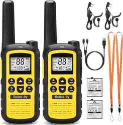
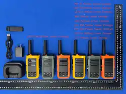
Thanks for choosing our radio. Please unbox and check whether the following accessories are
included and well-packed. If there’s anything missing or damaging after unboxed, please contact your
local distributor.
NO
Item Quantity
1
Radio
1
2 Charger 1
3
Belt Clip
1
4
User Manual
1
5
Guarantee Card
1
6
Adapter
1
7
USB line
1
3.
Familiar with Radio
3.1
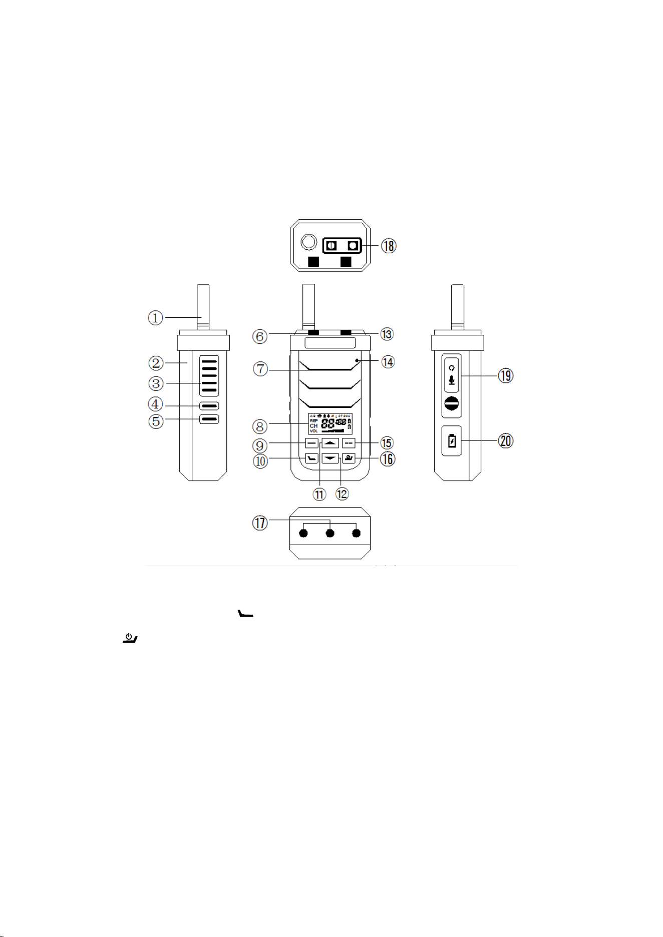
Radio Diagram
① Built-in RF Antenna ② Battery ③ PTT ④ side-key 1 ⑤ side-key 2 ⑥ Alarm Button ⑦ speaker
⑧ Display screen ⑨ ▂ key ⑩ key ⑪ ▲key ⑫ ▼key ⑬ Indicator Light ⑭ MIC ⑮
▂▂key ⑯ key ⑰ Water Immersion Detection Sensor ⑱ Alarm & Emergency Light ⑲
Earpiece and Programmable Jack ⑳ Charging port
3.2 LCD Icon Display
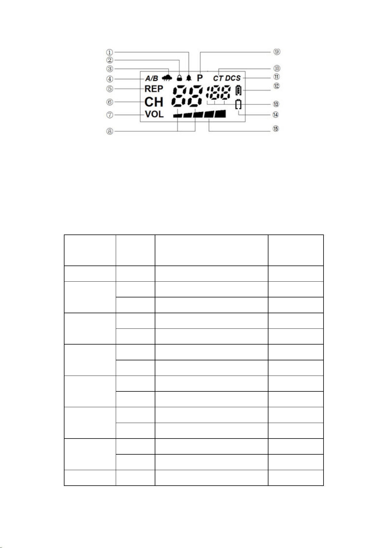
① Beep ② Keypad Lock ③ NOAA ④ Dual-Channel Standby ⑤ Channel (REP) Indicator ⑥ Channel
⑦ VOL ⑧ Channel Number & Function Indicator ⑨Power ⑩Analog CTCSS ⑪ Digital DCS ⑫
Battery Level Indicator⑬ CTCSS/DCS & Parameter Indicator⑭ Low Battery Indicator ⑮
Power/Field Strength Indicator
4. Function Description
4.1 Keypads Instruction
Keys
Trigger
Method
efinable function
definable
function
PTT
Long press
Transmit or Exit ×
Alarm Key
short press
Activate Alarm & Lighting Mode √
Long press
Emergency Alarm √
Side-key 1
short press
Increase Receive Volume ×
Long press
Monitor √
Side-key 2
short press
Decrease Receive Volume ×
Long press
scan √
▂
short press
Temporary Switch to Channel B √
Long press
Enter Channel B Selection Mode √
▲
short press
Channel+ ×
Long press
Fast Channel+ √
▼
short press
Channel- ×
Long press
Fast Channel- √
▂▂
short press
Display On/Off √
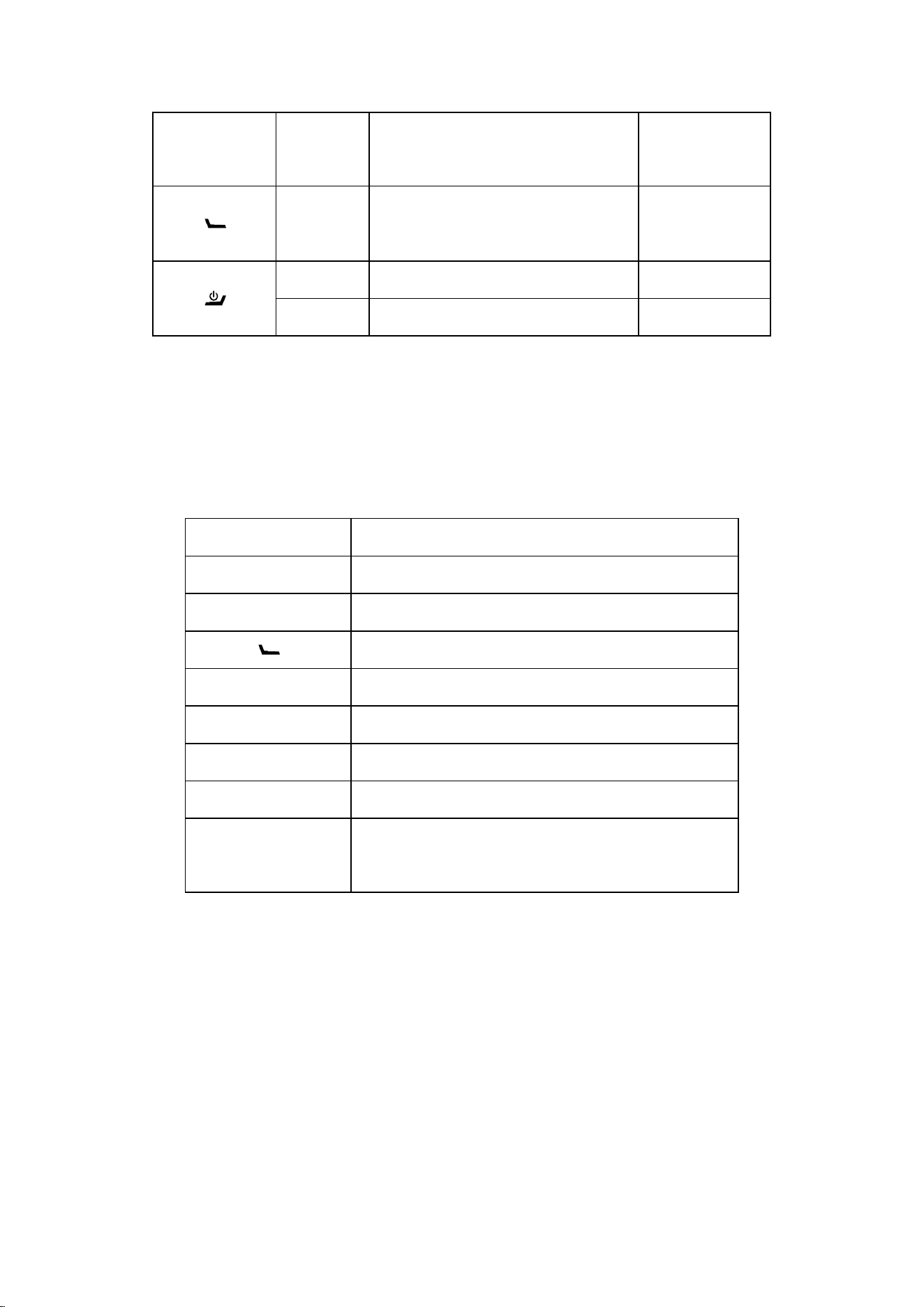
Long press
Speaker Water Removal
Vibration
√
Long press
Enter the DTMF input mode
√
short press
Display Battery power ×
Long press
Turn On/Off ×
4.2 Power-On Combination Key Functions
While powering on, press and hold the corresponding keys to activate the following functions:
Combination Key Function
▂ Enable/Disable Channel
Alarm Key Enable/Disable Voice Activation (VOX)
Enable/Disable Water Immersion Alarm
▲ Keypad Lock/Unlock
▼ Enable/Disable Key Beep
▂▂ Enable/Disable Vibration on Receive
Side-key 1
Enable/Disable Noise Reduction (Optional)
Side-key 1+Side-key
2
Enter Frequency Detection Mode
4.3 Transmitting
① Press PTT and will transmit at current frequency, and the indicator lights up red at the same time.
② VOX : When VOX transmission is enabled (configurable in advance, or via a user-defined key to
toggle VOX mode), the radio will automatically start transmitting when ambient sound exceeds the
preset threshold, with the indicator lighting up red. Transmission will stop automatically when
ambient sound falls below the preset threshold and remains there for longer than the preset VOX
delay time.
Note: If the optional Noise Reduction feature is installed, disable it before using VOX

transmission. Otherwise, ambient sound may be filtered out by AI Noise Reduction, preventing
VOX activation.
4.4 Receiving
① W hen a same-frequency signal is received, the indicator will light up green. If no CTCSS/DCS
tone is set for reception, or if the configured CTCSS/DCS tone matches that of the incoming signal,
the receiver audio will be activated.
② If the optional vibration motor is installed, you can enable or disable vibration alerts upon
reception. When enabled, the motor will vibrate for each incoming signal if the radio is idle. If the
radio is operated during this period, vibration will pause for a preset duration before resuming.
4.5 Channel Switching
① Short press the ▲ or ▼ key to sw i tch betw een preset val id channels.
② I f the l ong-press function of the ▲ or ▼ key remains set to the default Fast Channel Switch, long
press the ▲ or ▼ key to quickly switch between valid channels.
③ To sw itch to a channel, ensure the Channel function is enabled first (see Section 4.2).
4.6 Receive Volume Adjustment
The receive volume is divided into 10 levels (0–10).
Short press Side Key 1 to increase the volume level.
Short press Side Key 2 to decrease the volume level.
When the volume level is set to 0, no receive audio will be output. The volume setting status is
illustrated in the following diagram:
Note
:
Voice announcement and key beep sounds cannot be adjusted; they can only be
enabled or disabled.
4.7 Dual-Channel Standby
① Setting up Channel B for Dual-Channel Standby
Each channel can independently be assigned a dedicated Channel B for Dual-Channel Standby. First,
configure a key function as Set Channel B (default: long press the — key). When this key is

triggered, the radio enters Channel B setup mode, and the "A/B" icon flashes. Use the ▲ or ▼ key to
select a Channel B for the current channel:
If no operation is performed for 5 seconds, or if the PTT key is pressed, the setup mode will exit and
the settings will be discarded.
Press any other key to save the settings and exit setup mode.
② In standby mode, the radio monitors both the main channel (Channel A) and the configured
Channel B simultaneously. When a signal is detected on Channel B, the radio will temporarily switch
to Channel B to receive the call. After the call ends, it will remain on Channel B for 8 seconds to
wait for new activity. Pressing the PTT key will transmit on Channel B:
If no transmission or reception occurs for 8 consecutive seconds, the radio will automatically exit
Channel B mode.
Pressing any key will also exit Channel B mode.
③ Temporary Switch to Channel B
Configure a key function as A/B Channel Toggle (default: short press the — key). When this key is
triggered, the radio temporarily switches to Channel B for 8 seconds. While in Channel B mode,
pressing the PTT key will transmit on Channel B:
If no transmission or reception occurs for 8 consecutive seconds, the radio will automatically exit
Channel B mode.
Pressing any key will also exit Channel B mode.
4.8 Monitor
Configure a key function as Monitor (default: long press Side Key 1). When this key is triggered, the
receiver audio is activated to monitor voice traffic on the current channel.
4.9 Scanning
① Fi rst, assi gn a key functi on as Scan (defaul t: l ong press Si de K ey 2). W hen thi s key i s tri ggered,
the radio enters scanning mode and scans all channels added to the scan list.
② Scan Types:Three scan types are available: Carrier Operated (CO), Time Operated (TO), and
Search (SE).
CO Mode: If a signal is detected on the current scanning channel, the radio will stay on that channel
until the signal disappears, then resume scanning after a preset delay.
TO Mode: The radio will stay on the current scanning channel for a specified duration, then proceed

to the next channel regardless of whether a signal is present.
SE Mode: The radio will stop scanning and remain on the current scanning channel.
③ Change Scanning Direction:During scanning, press the ▲ or ▼ key to switch the scanning
direction.
④ Exit Scanning M ode:Press any key to exit scanning mode.If the post-scan return channel is set
to the current channel, the radio will stay on the last scanned channel after exiting.If set to return to
the initial channel, the radio will revert to the channel it was on before entering scanning mode.
4.10 Key Lock & Unlock
Assign the function of any key as Key Lock & Unlock. Press the key to lock or unlock all key
functions except PTT. If no key is assigned to the Key Lock & Unlock function, the device can also
be locked or unlocked via combination key operation while powering on (refer to Section 4.2).When
the keys are locked, the will appear on the display.
4.11 Light Mode
Assign the function of any key as Light Mode (default: short press the alarm key). Press the key to
switch between different light modes:
① Lighting Mode: White light stays on continuously for illumination.
② SOS Distress Mode: White light flashes in the SOS distress pattern of three short flashes, three
long flashes and three short flashes, once per minute.
③ Color Light Slow Flash: Red and blue lights flash alternately at 1-second intervals.
④ Color Light Fast Flash: Red and blue lights flash alternately at a faster speed.
4.12 Display On/Off
Assign the function of any key as
Display On/Off
(default: short press▂▂).
Press the key to toggle the display on or off.
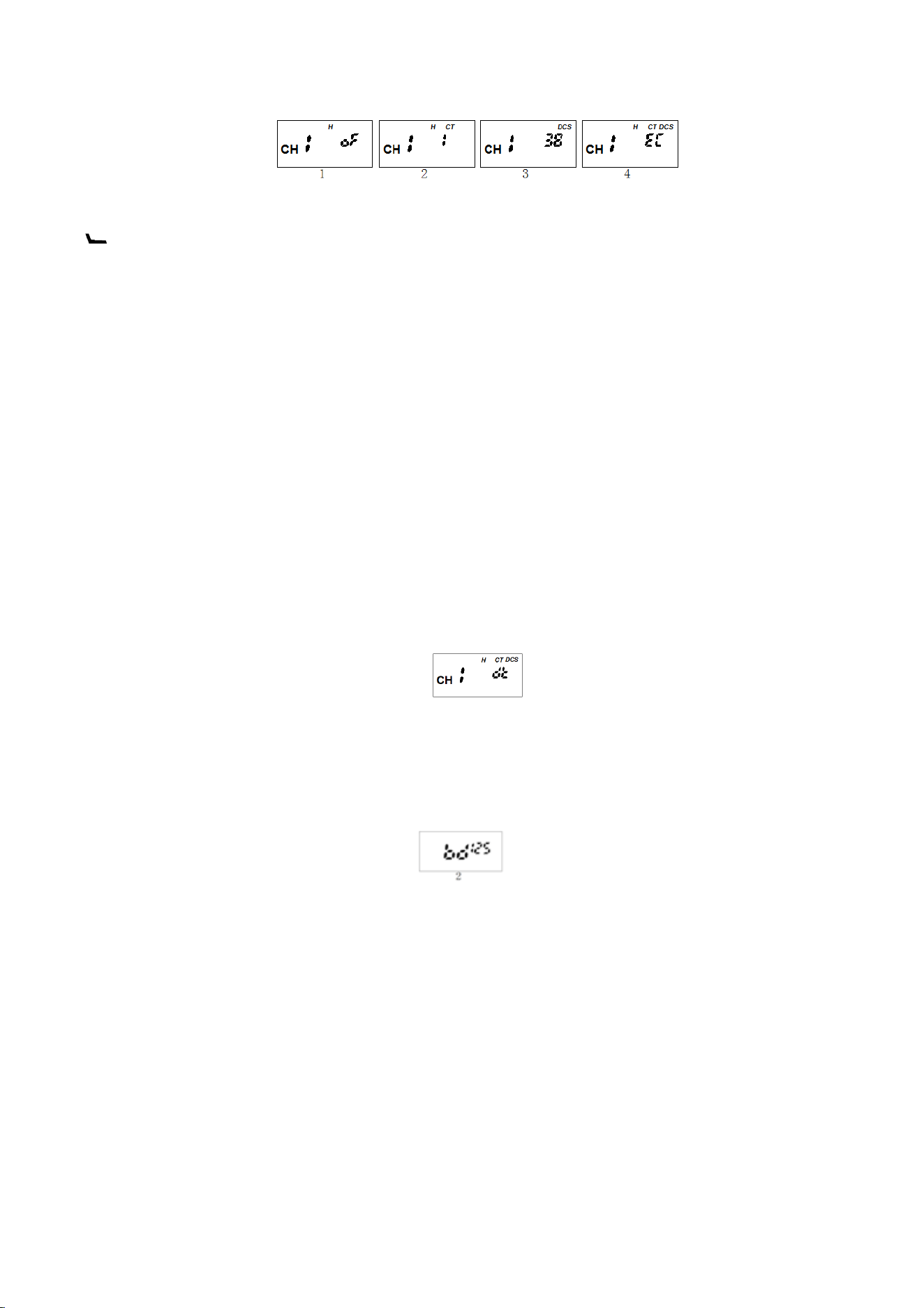
4.13 CTCSS Indication & Settings
① The figures below show the indications for different CTCSS types:Fig. 1 = No CTCSS; Fig. 2 =
Analog CTCSS; Fig. 3 = Digital CTCSS (DCS); Fig. 4 = Non-standard CTCSS.Refer to Appendix
Table 1 for the CTCSS code chart.
② Manual CTCSS Settings: Assign the function of any key as CTCSS Settings (default: long press the
key). Press the key to enter CTCSS setting mode, and the CT and DCS icons will flash
simultaneously. At this time, press the ▲ or ▼ key to adjust the CTCSS of the current channel.If no
operation is performed within 5 seconds, or if the PTT key is pressed, the settings will be canceled
and the mode will be exited. Press any other key to save the settings and exit the mode.(If the
device is currently on a channel, press any key to enter transmit CTCSS setting mode; press any key
again to save the settings and exit the mode.)
4.14 Remote CTCSS Decoding
Assign the function of any key as Remote CTCSS Decoding. Press the key to enter remote
CTCSS decoding mode, and the display will show "dt" as illustrated in the figure below.
In this mode, the device can quickly decode the CTCSS of signals within communication range
that match the receive frequency of the current channel. Once decoding is completed, the CTCSS of
the current channel will be replaced with the decoded value.
Press any key to exit decoding mode.
4.15 Bandwidth Switching
Assign the function of any key as Bandwidth Switching. Press the key to switch the working
bandwidth of the current channel.
Refer to the following figures for the display indications: Fig. 2 = Narrowband 12.5KHz
4.16 Emergency Alarm
Assign the function of any key as Emergency Alarm (default: long press the alarm key). Press the
key to enter alarm mode.
This device is equipped with the following alarm modes:
① Local Alarm: When triggered, the device emits a sharp alarm sound to alert people nearby of
an emergency.
② Remote Alarm: When triggered, the device will not emit any alarm sound itself, but
continuously transmit sharp alarm sounds to remote devices on the same frequency to notify them.
This function can be used to send a distress signal in emergency situations where it is inconvenient to
make a sound.
③ Local + Remote Alarm: When triggered, the device emits a sharp alarm sound and
simultaneously transmits the alarm sound to remote devices on the same frequency.
④ MDC Signaling Alarm: When triggered, the device will initiate a call to remote devices on the
same frequency every 20 seconds, with each call lasting 10 seconds to allow remote devices to
monitor the surroundings of the device. After the 10-second call ends, the device will send an MDC
signal. For devices of some brands with a display screen, receiving this signal may trigger a message
"XXX needs help!" to show on the screen. For devices of the same model as this one, receiving the
signal will trigger a voice announcement of "XXX needs help!". XXX refers to the pre-edited device ID
entered by the user.
This alarm mode is suitable for distress calls during team activities.
Users can pre-configure a light effect for the alarm state when using the device’s alarm function:
• If white light alarm is selected, the white light will turn on and flash in SOS distress mode
when the alarm is triggered.
• If color light alarm is selected, the red and blue lights will flash rapidly alternately when the
alarm is triggered.
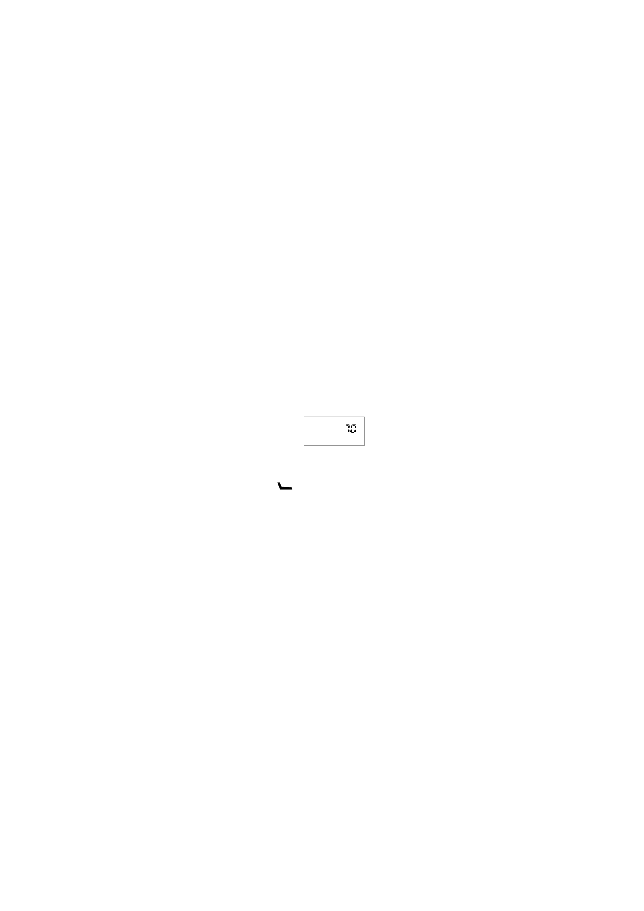
4.17 ID Inquiry
Assign the function of any key as ID Inquiry. Press the key to check the device ID.
For example, the display of Device ID 70 after inquiry is shown in the figure below.
4.18 Water Immersion Alarm & Speaker Water Drainage
① Water Immersion Alarm: Press the key while powering on to toggle the alarm ON or OFF.
The alarm method and indicator light are basically the same as those specified in Section 4.17. The
difference is that when using MDC signaling for alarm, the water immersion alarm will send the
command: "XXX has fallen into water!"
②Automatic Speaker Water Drainage:When the device is removed from water and the alarm
is deactivated, it will emit a 165Hz audio tone continuously for 60 seconds to vibrate the speaker and
expel tiny water droplets. Press any key to stop the audio tone.
③
Manual Water Drainage
:Assign the function of any key as
Speaker Water
Drainage (default: long press▂▂),Press the key to trigger the device to emit a 165Hz audio
tone for 60 seconds for water drainage.
4.19 Channel Off-Net Mode
Assign the function of any key as Channel Off-Net Mode. Press the key to toggle the mode ON or
OFF if the device is currently operating on a channel.
When Off-Net Mode is activated, the REP icon will flash, and the transmit frequency will be set
to match the receive frequency. When Off-Net Mode is deactivated, the REP icon will stop flashing.
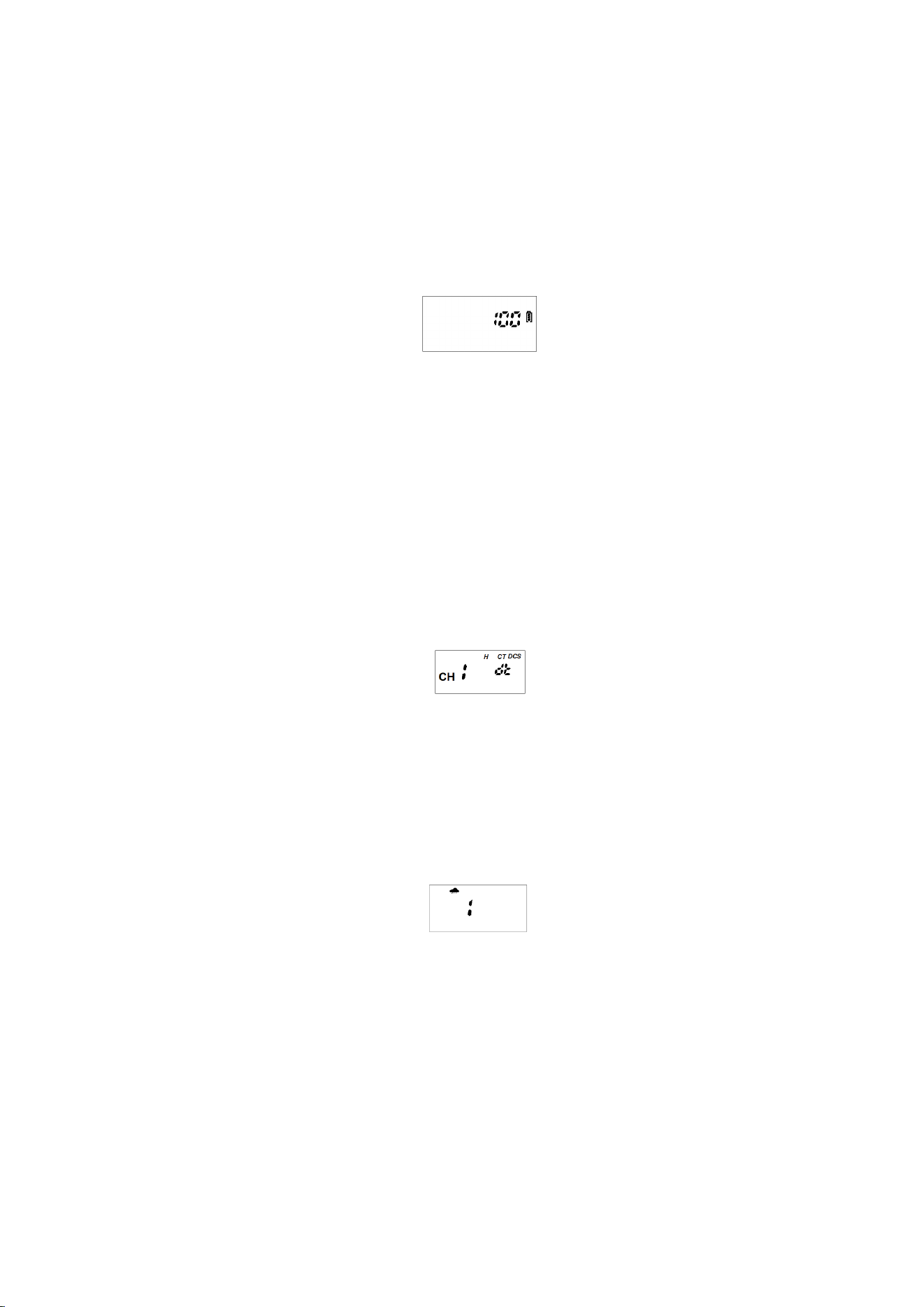
4.20 Battery Level Inquiry & Low Battery Alert
Short-press the Power Key to check the device’s remaining battery percentage. (This value is an
estimated figure with accuracy error, for reference only.)
When the battery voltage is too low, the icon will start flashing. Users are advised to charge the
device promptly.
The battery level display is shown in the figure below.
4.21 Frequency Detection & Decoding Function
Press Side Key 1 and Side Key 2 simultaneously while powering on the device to enter
frequency detection and decoding mode.
In this mode, the device can quickly detect the frequency and CTCSS of nearby transmitting
devices, and save the detected data to overwrite the current channel.
After detection is completed, press any key (excluding PTT, Volume, Channel Switch and Power
keys
) to restart detection.
During detection mode, switching to channels is not allowed, but switching to empty channels is
permitted. This enables users to add frequency information to empty channels by using the frequency
detection & decoding function.
4.22 NOAA
Assign the function of any key as NOAA. Press the key to enter weather radio monitoring mode.
If no signal is received on the current weather channel within 6 seconds, the device will
automatically start scanning the signals of 11 weather radio channels. Refer to Appendix Table 2 for
the frequency chart of these 11 weather radio channels.
The weather radio status indication is shown in the figure
4.23 Noise Reduction (Optional Function)
Assign the function of any key as Noise Reduction (NR). Press the key to toggle the function
ON or OFF.
In NR mode, the device effectively filters out ambient noise and amplifies human voices,
delivering clearer call quality. This mode is recommended for operation in noisy environments.
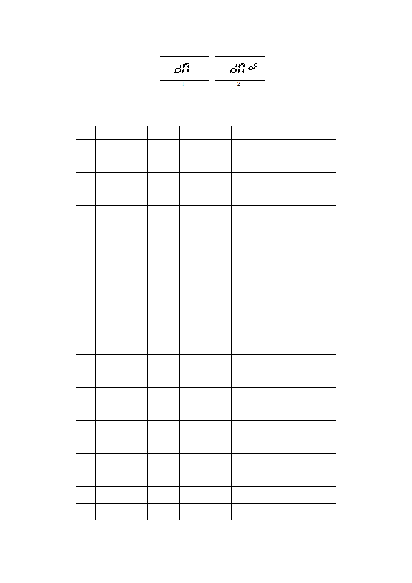
Refer to the figures below for the function status prompts:Fig. 1 = NR ON; Fig. 2 = NR OFF
5. Appendix Table
5.1 Appendix Table 1: CTCSS Serial Number & Code Chart
NO
CTCSS
NO
DCS
NO
DCS
NO
CTCSS
NO
DCS
1 67.0 39 D023N 81 D315N 122 69.3 135 D036N
2 71.9 40 D025N 82 D331N 123 159.8 136 D053N
3 74.4 41 D026N 83 D343N 124 165.5 137 D122N
4 77.0 42 D031N 84 D346N 125 171.3 138 D145N
5 79.7 43 D032N 85 D351N 126 177.3 139 D212N
6 82.5 44 D043N 86 D364N 127 177.8 140 D225N
7 85.4 45 D047N 87 D365N 128 183.5 141 D246N
8 88.5 46 D051N 88 D371N 129 189.9 142 D252N
9 91.5 47 D054N 89 D411N 130 196.6 143 D255N
10 94.8 48 D065N 90 D412N 131 199.5 144 D266N
11 97.4 49 D071N 91 D413N 132 206.5 145 D274N
12 100.0 50 D072N 92 D423N 133 229.1 146 D325N
13 103.5 51 D073N 93 D431N 134 254.1 147 D332N
14 107.2 52 D074N 94 D432N 148 D356N
15 110.9 53 D114N 95 D445N 149 D446N
16 114.8 54 D115N 96 D464N 150 D452N
17 118.8 55 D116N 97 D465N 151 D454N
18 123.0 56 D125N 98 D466N 152 D455N
19 127.3 57 D131N 99 D503N 153 D462N
20 131.8 58 D132N 100 D506N 154 D523N
21 136.5 59 D134N 101 D516N 155 D526N
22 141.3 60 D143N 102 D532N
23 146.2 61 D152N 103 D546N
24 151.4 62 D155N 104 D565N
25 156.7 63 D156N 105 D606N
26 162.2 64 D162N 106 D612N
27 167.9 65 D165N 107 D624N
28 173.8 66 D172N 108 D627N
29 179.9 67 D174N 109 D631N
30 186.2 68 D205N 110 D632N
31 192.8 69 D223N 111 D654N
32 203.5 70 D226N 112 D662N
33 210.7 71 D243N 113 D664N
34 218.1 72 D244N 114 D703N
35 225.7 73 D245N 115 D712N
36 233.6 74 D251N 116 D723N
37 241.8 75 D261N 117 D731N
38 250.3 76 D263N 118 D732N
77 D265N 119 D734N
78 D271N 120 D743N
79 D306N 121 D754N
80 D311N
5.2 Appendix Table 2: NOAA Weather Radio Frequency Chart
1 162.550 7 162.5250
2 162.400 8 161.650
3 162.475 9 161.775
4 162.425 10 161.750
5 162.450 11 162.000
6 162.500
6. Specifications
General Part
Frequency Range:
TX/RX: 462.5500-462.7250MHz,
467.5625-467.7125MHz
Channel Capacity
22
Channel Spacing
(
W/N
)
12.5kHz
Voltage
3.7VDC
Working Mode
Same frequency simplex,different frequency
simplex
Antenna
Spring
Frequency Stability
±2.5ppm
Working Temperature
-
20 ~
+
60
℃
Dimension
175 X 58 X 38 mm about 182g
(
Including
Antenna; Excluding Belt Clip
)
Transmitting
Modulation Mode
F3E
Maximum deviation
(
W/N
)
≤5KHz /≤2.5KHz
SNR
(
W/N
)
-45dB/ -40dB
TX Current
≤1300mA
Receiving
Sensitivity
(
W/N
)
0.22μV/ 0.25μV 12dB SINAD
Inter modulation
(
W/N)
65dB/ 60dB
Audio Distortion
<
5
%
Audio Output Power
≤1W
(
8 Ω
)
RX Current
≤500mA
Standby Current
≤60mA
Note: The above parameters are subject to change without prior notice!
FCC Statement
Any Changes or modifications not expressly approved by the party responsible for compliance could
void the user's authority to operate the equipment.

This device complies with part 15 of the FCC Rules. Operation is subject to the following two
conditions:
1) This device may not cause harmful interference.
2)This device must accept any interference received, including interference that may cause undesired
operation.
Note:
This equipment has been tested and found to comply with the limits for a Class B digital device,
pursuant to part 15 of the FCC Rules. These limits are designed to provide reasonable protection
against harmful interference in a residential installation.
This equipment generates, uses and can radiate radio frequency energy and, if not installed and used
in accordance with the instructions, may cause harmful interference to radio communications.
However, there is no guarantee that interference will not occur in a particular installation. If this
equipment does cause harmful interference to radio or television reception, which can be determined
by turning the equipment off and on, the user is encouraged to try to correct the interference by one
or more of the following measures:
- Reorient or relocate the receiving antenna.
- Increase the separation between the equipment and receiver.
- Connect the equipment into an outlet on a circuit different from that to which the receiver is
connected.
- Consult the dealer or an experienced radio / TV technician for help.
SAR tests are conducted using standard operating positions accepted by the FCC with the device
transmitting certified power level, the actual SAR level of the device while operating can be well
below the maximum value.
For body worn operation, this device has been tested and meets the FCC RF exposure guidelines
when used with for this product or when used with and accessory that contains no metal.
The maintain compliance with the FCC's RF exposure guidelines, hold the transmitter and antenna at
least 1 inch(2.5 centimeters) from your face and speak in a normal voice, with the antenna pointed up
and away from the face.,
This equipment complies with FCC radiation axposure limits set forth for an uncontrolled
environment. In order to comply with the FCC RF exposure requirements, the antenna installation
must comply with following:
Users must be fully aware of the hazards of the exposure and able to exercise control over their RF
exposure to qualify for the higher exposure limits.
Your wireless hand-held portable transceiver contains a low power transmitter. This product sends
out radiot Push-to-Talk (PTT) Button is pressed.
The device is authorized to operate at a duty factor not to exceed 75%.